
Allocation Journal - System Power Optimization and ...
14
IEEE TRANSACTIONS ON COMPUTER-AIDED DESIGN OF INTEGRATED CIRCUITS AND SYSTEMS, VOL. 32, NO. 7, JULY 2013 1003 Charge Allocation in Hybrid Electrical Energy Storage Systems Qing Xie, Student Member, IEEE, Yanzhi Wang, Student Member, IEEE, Younghyun Kim, Member, IEEE, Massoud Pedram, Fellow, IEEE, and Naehyuck Chang, Fellow, IEEE Abstract —A hybrid electrical energy storage (HEES) system consists of multiple banks of heterogeneous electrical energy storage (EES) elements placed between a power source and some load devices and providing charge storage and retrieval functions. For an HEES system to perform its desired functions of 1) reducing electricity costs by storing electricity obtained from the power grid at off-peak times when its price is lower, for use at peak times instead of electricity that must be bought then at higher prices, and 2) alleviating problems, such as excessive power fluctuation and undependable power supply, which are associated with the use of large amounts of renewable energy on the grid, appropriate charge management policies must be developed in order to efficiently store and retrieve electrical energy while attaining performance metrics that are close to the respective best values across the constituent EES banks in the HEES system. This paper is the first to formally describe the global charge allocation problem in HEES systems, namely, distributing a specified level of incoming power to a subset of destination EES banks so that maximum charge allocation efficiency is achieved. The problem is formulated as a mixed integer nonlinear program with the objective function set to the global charge allocation efficiency and the constraints capturing key requirements and features of the system such as the energy conservation law, power conversion losses in the chargers, the rate capacity, and self-discharge effects in the EES elements. A rigorous algorithm is provided to obtain near-optimal charge allocation efficiency under a daily charge allocation schedule. A photovoltaic array is used as an example of the power source for the charge allocation process and a heuristic is provided to predict the solar radiation level with a high accuracy. Simulation results using this photovoltaic cell array and a representative HEES system demonstrate up to 25% gain in the charge allocation efficiency by employing the proposed algorithm. Index Terms—Charge allocation, charge management, energy efficiency, energy storage system (ESS), hybrid energy storage system (HESS). Manuscript received October 1, 2012; revised December 30, 2012; accepted January 28, 2013. Date of current version June 14, 2013. This work was supported in part by grants from the Software and Hardware Foundations of the Division of Computer and Communication Foundations, U.S. National Science Foundation, the Brain Korea 21 Project, the National Research Foundation of Korea grant funded by the Korean Government (MEST), under Grant 20120005640, and the Institute of Computer Technology, Seoul National University. This paper was recommended by Associate Editor Prof. J. Henkel. Q. Xie, Y. Wang, and M. Pedram are with the Department of Electrical Engineering, University of Southern California, Los Angeles, CA 90089 USA (e-mail: [email protected]; [email protected]; [email protected]). Y. Kim and N. Chang are with the Department of Electrical Engineering and Computer Science, Seoul National University, Seoul 151-742, Korea (e-mail: [email protected]; [email protected]). M. Pedram and N. Chang are the co-corresponding authors. Color versions of one or more of the figures in this paper are available online at http://ieeexplore.ieee.org. Digital Object Identifier 10.1109/TCAD.2013.2250583 I. Introduction E LECTRICAL energy is a high-quality form of energy [2] in the sense that 1) it can be easily and efficiently converted to other forms of energy, and 2) it can be used to control other (lower quality) forms of energy. However, elec- tricity generation and consumption are typically not matched with each other. From utility company’s perspective, storing the excess energy avoids energy wastage and mitigates overin- vestment in power generation facilities by shaving the power demand during peak usage hours. Electrical energy storage (EES) systems thus increase the availability of electrical en- ergy, mitigate the supply-demand mismatches, and reduce the generation capacity required to meet the peak power demand [3]–[5]. From consumers’ perspective, storing energy obtained from the grid or generated by local power generation sources (such photovoltaic modules) during off-peak hours and using the stored energy to reduce the usage of grid electricity during peak hours can result in sizeable cost savings [6], [7]. Conventional EES systems are mainly homogeneous, i.e., they consist of a single type of EES element. Unfortunately, none of the existing EES elements can satisfy all the de- sired performance metrics such as high power and energy density, low cost and weight per unit capacity, high round- trip efficiency, and long cycle life. This limitation prevents the adoption of a wide range of socially and economically useful technologies, such as the widely adopted grid-scale EES and electric vehicles (EVs). Hence, eliminating this limitation of homogeneous EES systems is the primary motivation of our paper. Hybrid electrical energy storage (HEES) systems address this fundamental shortcoming of the conventional ho- mogeneous EES systems using a collection of heterogeneous EES elements that are suitably organized and accessed [8], [9]. Each type of the EES elements has its unique strength and weakness. The HEES system can exploit the strength of each type of the EES element and achieve a combination of performance metrics that is superior to that of any of its individual EES components. Appropriate charge manage- ment policies, including charge allocation, charge replacement, charge migration, and bank reconfiguration, are designed ac- cording to the source/load profiles and characteristics of the HEES systems, in order to achieve the near-optimal overall performance metrics [1], [10]–[16]. We start by introducing a generalized HEES architec- ture comprised of two representative types of EES elements (batteries and supercapacitors) connected by a charge transfer 0278–0070/$31.00 c 2013 IEEE
Transcript of Allocation Journal - System Power Optimization and ...
IEEE TRANSACTIONS ON COMPUTER-AIDED DESIGN OF INTEGRATED CIRCUITS AND SYSTEMS, VOL. 32, NO. 7, JULY 2013 1003
Charge Allocation in Hybrid Electrical EnergyStorage Systems
Qing Xie, Student Member, IEEE, Yanzhi Wang, Student Member, IEEE, Younghyun Kim, Member, IEEE,Massoud Pedram, Fellow, IEEE, and Naehyuck Chang, Fellow, IEEE
Abstract—A hybrid electrical energy storage (HEES) systemconsists of multiple banks of heterogeneous electrical energystorage (EES) elements placed between a power source andsome load devices and providing charge storage and retrievalfunctions. For an HEES system to perform its desired functionsof 1) reducing electricity costs by storing electricity obtained fromthe power grid at off-peak times when its price is lower, for useat peak times instead of electricity that must be bought thenat higher prices, and 2) alleviating problems, such as excessivepower fluctuation and undependable power supply, which areassociated with the use of large amounts of renewable energyon the grid, appropriate charge management policies must bedeveloped in order to efficiently store and retrieve electricalenergy while attaining performance metrics that are close tothe respective best values across the constituent EES banks inthe HEES system. This paper is the first to formally describethe global charge allocation problem in HEES systems, namely,distributing a specified level of incoming power to a subsetof destination EES banks so that maximum charge allocationefficiency is achieved. The problem is formulated as a mixedinteger nonlinear program with the objective function set to theglobal charge allocation efficiency and the constraints capturingkey requirements and features of the system such as the energyconservation law, power conversion losses in the chargers, therate capacity, and self-discharge effects in the EES elements.A rigorous algorithm is provided to obtain near-optimal chargeallocation efficiency under a daily charge allocation schedule. Aphotovoltaic array is used as an example of the power sourcefor the charge allocation process and a heuristic is provided topredict the solar radiation level with a high accuracy. Simulationresults using this photovoltaic cell array and a representativeHEES system demonstrate up to 25% gain in the chargeallocation efficiency by employing the proposed algorithm.
Index Terms—Charge allocation, charge management, energyefficiency, energy storage system (ESS), hybrid energy storagesystem (HESS).
Manuscript received October 1, 2012; revised December 30, 2012; acceptedJanuary 28, 2013. Date of current version June 14, 2013. This work wassupported in part by grants from the Software and Hardware Foundations ofthe Division of Computer and Communication Foundations, U.S. NationalScience Foundation, the Brain Korea 21 Project, the National ResearchFoundation of Korea grant funded by the Korean Government (MEST), underGrant 20120005640, and the Institute of Computer Technology, Seoul NationalUniversity. This paper was recommended by Associate Editor Prof. J. Henkel.
Q. Xie, Y. Wang, and M. Pedram are with the Department of ElectricalEngineering, University of Southern California, Los Angeles, CA 90089 USA(e-mail: [email protected]; [email protected]; [email protected]).
Y. Kim and N. Chang are with the Department of Electrical Engineering andComputer Science, Seoul National University, Seoul 151-742, Korea (e-mail:[email protected]; [email protected]).
M. Pedram and N. Chang are the co-corresponding authors.Color versions of one or more of the figures in this paper are available
online at http://ieeexplore.ieee.org.Digital Object Identifier 10.1109/TCAD.2013.2250583
I. Introduction
ELECTRICAL energy is a high-quality form of energy[2] in the sense that 1) it can be easily and efficiently
converted to other forms of energy, and 2) it can be used tocontrol other (lower quality) forms of energy. However, elec-tricity generation and consumption are typically not matchedwith each other. From utility company’s perspective, storingthe excess energy avoids energy wastage and mitigates overin-vestment in power generation facilities by shaving the powerdemand during peak usage hours. Electrical energy storage(EES) systems thus increase the availability of electrical en-ergy, mitigate the supply-demand mismatches, and reduce thegeneration capacity required to meet the peak power demand[3]–[5]. From consumers’ perspective, storing energy obtainedfrom the grid or generated by local power generation sources(such photovoltaic modules) during off-peak hours and usingthe stored energy to reduce the usage of grid electricity duringpeak hours can result in sizeable cost savings [6], [7].
Conventional EES systems are mainly homogeneous, i.e.,they consist of a single type of EES element. Unfortunately,none of the existing EES elements can satisfy all the de-sired performance metrics such as high power and energydensity, low cost and weight per unit capacity, high round-trip efficiency, and long cycle life. This limitation preventsthe adoption of a wide range of socially and economicallyuseful technologies, such as the widely adopted grid-scale EESand electric vehicles (EVs). Hence, eliminating this limitationof homogeneous EES systems is the primary motivation ofour paper. Hybrid electrical energy storage (HEES) systemsaddress this fundamental shortcoming of the conventional ho-mogeneous EES systems using a collection of heterogeneousEES elements that are suitably organized and accessed [8],[9]. Each type of the EES elements has its unique strengthand weakness. The HEES system can exploit the strength ofeach type of the EES element and achieve a combinationof performance metrics that is superior to that of any ofits individual EES components. Appropriate charge manage-ment policies, including charge allocation, charge replacement,charge migration, and bank reconfiguration, are designed ac-cording to the source/load profiles and characteristics of theHEES systems, in order to achieve the near-optimal overallperformance metrics [1], [10]–[16].
We start by introducing a generalized HEES architec-ture comprised of two representative types of EES elements(batteries and supercapacitors) connected by a charge transfer
0278–0070/$31.00 c© 2013 IEEE

1004 IEEE TRANSACTIONS ON COMPUTER-AIDED DESIGN OF INTEGRATED CIRCUITS AND SYSTEMS, VOL. 32, NO. 7, JULY 2013
Fig. 1. Concept diagram of the HEES systems.
interconnect (CTI) and then build the corresponding elec-trical circuit models for power converters, and battery andsupercapacitor banks. Next, we introduce the global chargeallocation (GCA) problem for an HEES system, i.e., how todistribute the given source power supply to some selectedEES destination banks in the HEES system so that the GCAefficiency1 is maximized. This efficiency is determined by thecharacteristics of the selected banks and the magnitudes of thecharging currents, and the states of charge (SoCs) of the banks.We consider the energy conservation and charge conservationduring the charge allocation process. In addition to the energypushed into all EES banks, we also take into account the powerdissipation on the internal resistances of battery banks andsupercapacitor banks, the power loss on chargers during thepower conversion process, the rate capacity effect in batteries,and the self-discharge in supercapacitors.
The GCA problem may be decomposed into threesubproblems.
1) What is the optimal voltage level setting for the CTI?2) Which EES bank(s) should be selected among all the
destination EES banks?3) How should the charging current for each of the selected
destination EES banks be assigned?
The GCA efficiency depends on the profile of the powersource, magnitude of charging currents, and SoCs of each EESbanks. Since SoCs of EES banks and the amount of source(input) power vary over time, and solutions to these threequestions are interdependent, our method is an online, iterativeapproach. The charge allocation efficiency also depends ondetailed characteristics of the external power source. We adopta photovoltaic (PV) cell array as the incoming power source.An accurate forecast of the PV power is extremely importantfor us to develop for the GCA policy. We predict the solarradiation level based on the history of solar irradiance levelsand the current observation.
1GCA efficiency is defined as the ratio between energy that is pushed intoall EES banks and the total energy provided by all the power sources, duringthe whole charge allocation process for the EES system.
We formulate the GCA problem as a mixed-integer non-linear programming (MINLP) problem, which unfortunatelycannot be optimally solved in polynomial time. We, therefore,break the whole charge allocation process into a series of timeslots and at every decision epoch (which denotes the boundarybetween consecutive time slots), we solve an instantaneouscharge allocation (ICA) problem, which seeks to optimizethe charge allocation efficiency at a specific instance of time.The ICA problem is still an MINLP problem. However, wecan simplify the ICA problem, and subsequently develop aneffective way of solving the ICA problem in an iterativemanner, where in each iteration the optimization problemis convex. We incorporate appropriate charging power limitsfor the high-charging-efficiency EES banks to the problemformulation to ensure that the charge allocation managerconsiders the future energy generation profile, and thus avoidgreedy decisions that can result in significant future efficiencydegradation. The charging power limits are derived using theLagrange multiplier method to minimize the energy loss dueto the rate capacity effect and self-discharge. The near-optimalsolution of the original GCA problem is obtained by solvingthe ICA problem with charging power upper limit for high-charging-efficiency banks at every decision epoch throughoutthe charge allocation process. We record the ICA solutionsto obtain the GCA solutions. Simulation results show thatthe percentage improvement of energy harvesting ability fromvarious baseline setups ranges from 5% to 25% in general.
II. HEES Systems
A. Related Work
Considerable efforts have been invested in exploring theoptimal architecture of the HEES systems. A direct-parallelconnection of the battery and supercapacitor [17], [18] issimple but has major weaknesses because the shared terminalvoltage of both sources must be kept same, which limitsthe capacity utilization of the supercapacitor and disables theactive current distribution control. A cascade dc–dc converterbetween the battery and supercapacitor [19] can isolate thepower sources and allow higher supercapacitor utilization.However, this design is targeted to a predefined charge man-agement scenario whereby the supercapacitor is used as abattery buffer all the time. A more general architecture isa dc bus with distributed converters [20], [21]. However,the previous dc-bus architectures do not change the dc-busvoltage, which prevents them from achieving a higher systemefficiency. The proposed HEES system resembles the dc-bustopology, but employs optimal control of the dc-bus voltageand does proper current distribution to each bank at run time.
Proper charge management on top of the hybrid EESarchitecture will be crucial if the architecture has some degreeof freedom both at design and run times. A circuit model helpsderive a desirable capacity ratio between the battery and su-percapacitor, based on the peak power [22]. The configurationof a supercapacitor and the duty ratio as well as the pulsefrequency of the load profile were considered in optimizingHEES performance in [23]. However, none of the previouswork has introduced a general HEES management because the

XIE et al.: CHARGE ALLOCATION IN HYBRID ELECTRICAL ENERGY STORAGE SYSTEMS 1005
Fig. 2. Architecture of the proposed HEES system.
previous HEES architectures are mostly dedicated to particularoperation scenarios. In contrast, this paper presents the generalform of the GCA problem, formulates it as a mathematicalprogramming problem, and provides a near-optimal solution.
B. Motivation of HEES Systems
A conceptual drawing of the proposed HEES systems isdepicted in Fig. 1. The system comprises of a number ofheterogeneous EES banks, connecting to CTI through dis-tributed power converters (not displayed in the figure). Aswe mentioned earlier, no existing EES elements fulfill all therequirements of an ideal energy storage system such as lowcapital cost, high cycle efficiency, long cycle life, low self-discharge rate, and high power and energy densities. Therefore,instead of relying on a single type of EES element technology,HEES systems use multiple heterogeneous EES elements.
Different types of EES elements have distinct characteris-tics. For example, a Li-ion battery bank has high energy capac-ity, low self-discharge, stable open terminal voltage, and rela-tive low cost, but suffers from a low rate capability. In contrast,a supercapacitor bank has superior cycle efficiency, long cyclelife, and high capability capability, but small energy densityand high self-discharge rate. Therefore, heterogeneous EESbanks, with properly designed charge management policies,can be used in a complementary manner to exploit the bestcharacteristics (strengths) of each type of EES element, whilehiding their weaknesses. The charge management policiesinclude charge allocation [1], charge migration [10], [13], [16],charge replacement [12], and EES bank reconfiguration [11].
C. HEES System Architecture
Fig. 2 depicts the block diagram of the proposed HEES ar-chitecture. All heterogeneous EES banks are connected to eachother via the CTI. An EES bank includes a set of homogeneousEES elements and a bidirectional converter since a typicalEES element has a low voltage rating and a small energycapacity. These EES elements are organized in an appropri-ately constructed 2-D array using reconfigurable series and/orparallel connections. The bidirectional converters control thevoltage and current when charging or discharging the EESarray since there is generally a voltage difference between theCTI and the EES array. The bidirectional converters supportthe following two operation modes: 1) voltage regulationmode, the bidirectional converter generates a desirable output
Fig. 3. Schematic of the charge allocation process in an HEES system.
voltage regardless of the variation of the input power; and 2)current regulation mode, the bidirectional converter generates adesirable output current regardless of the variation of the inputpower. We refer to it as a charger if the converter is in thismode. The dc and ac power sources are connected to the HEESsystem using the unidirectional converters that only allowcurrent flows onto the CTI. We use dc–dc converters and dc–ac inverters for the load devices to maintain the compatibilityof the voltage levels between the CTI and load devices.
The charge management policies control the EES bankreconfiguration, CTI connection, CTI voltage, and chargingcurrents/discharging current of each EES bank at each time in-stance in order to achieve the best HEES system performance.We control both the CTI voltage and charging/dischargingcurrent of EES arrays using the following method. We operateone converter in the voltage regulation mode to determine thedesirable CTI voltage and all other converters in the currentregulation mode. The output current for the voltage regulationconverter is automatically determined since the total currentflowing into CTI equals the total current flowing outward. Thiscontrol scheme ensures the stability of CTI voltage and bankcurrents while we generate the software-level real-time tasksto implement the high-level charge management policies.
D. Charge Allocation Problem Statement
Charge allocation policy is used to determine the mostsuitable CTI voltage, a subset of EES banks, and the amountof charging current for each selected EES bank, in order tostore the maximum amount of energy provided to the HEESsystem from a given power source, i.e., PV cells, a windmill,the power grid, and so on. The optimal charge allocationpolicy depends on the energy generation profile, i.e., it ideallydistributes the incoming power at each time instance to theselected destination banks and achieves the highest possibleGCA efficiency, which means that the maximum amount ofenergy is pushed into the selected EES banks. Thus, theprediction of the energy generation profile is important whenattempting to determine the optimal charge allocation policy.Note that the charge allocation policy is also affected by theaccuracy of the load profile prediction. This problem, however,falls outside the scope of this paper.

1006 IEEE TRANSACTIONS ON COMPUTER-AIDED DESIGN OF INTEGRATED CIRCUITS AND SYSTEMS, VOL. 32, NO. 7, JULY 2013
TABLE I
Notation Used in Sections II and III-B
NotationS full set of all EES banks in an HEES systemS′(t) selection set among all EES banks in an HEES systemSoCk(t) state of charge of the kth EES arrayV OC
array,k(t) open-circuit voltage (OCV) of the kth EES array
V CCarray,k(t) closed-circuit voltage (CCV) of the kth EES array
Vcti(t) voltage level on the charge transfer interconnectVsrc(t) output voltage at the terminal of the power sourcePc,s(t) power loss in sth source-to-CTI chargerPc,k(t) power loss in charging control charger in the kth EES
bankPsd,k(t) power loss due to the self-discharge in the kth EES
bankIbank,k(t) bank charging current of the kth bank, seen at the
input of chargerIarray,k(t) array charging current of the kth bank, seen at the
output of chargerPwaste(t) excessive amount of input power that cannot be
allocated to any EES banks
Fig. 3 shows a conceptual diagram of the charge allocationsubsystem in an HEES system. Table I lists the importantnotations used in the following text. The system contains N
heterogeneous EES banks, each of which consists of a numberof homogeneous EES elements. Each EES bank is connectedto the CTI through a charger. Supposing a charge allocationprocess starts at time t = 0 and ends at time t = Ta, for allt ∈ [0, Ta], a subset S′(t) ⊆ S is selected among the N EESbanks to receive energy from the power sources through theCTI and the intervening chargers.
The source-to-CTI charger supports high voltage and currentlevels and regulates the output voltage of the power sourceVsrc(t) to CTI voltage Vcti(t) through a feedback loop, sub-jecting to a conversion power loss of Pc,s(t). The currentflows from the source, through the CTI, into (a selected set)of chargers that connect the CTI and the destination EESbanks. Since Vcti(t) affects the conversion efficiency of thepower converters, choosing the optimal Vcti(t) is crucial for thecharge allocation problem. The kth charger converts the bankcharging current Ibank,k(t) to array charging current, Iarray,k(t),with a power loss of Pc,k(t). Note that the open-circuit voltage(OCV) of the kth EES array V OC
array,k(t) is normally usedwhen discussing the battery status; however, the closed-circuitvoltage CCV of the kth EES array V CC
array,k(t) is the voltagethat we should consider for the accompanying circuits. Therelationship between V OC
array,k(t) and V CCarray,k(t) will be discussed
in Section III-A. The self-discharge rate of the kth EES bankPsd,k(t) also depends on the SoC and bank properties. In casethat the input power exceeds the maximum receiving capabilityof the HEES system, the excess input power Pwaste(t) cannotbe stored and must be dumped to the ground (dissipated asheat). A formal definition of the charge allocation efficiencyis presented in Section III-B.
III. Problem Formulation
A. System Models
Table II lists the important notations used in the followingtext.
1) PV Model: The output power of the PV module Ppv
is mainly determined by the voltage and the current of thePV module, Vpv and Ipv, the solar radiation level G, the
TABLE II
Notation Used in Sections III-B and IV
NotationPpv output power of the PV module, obtained using MPTT
technique [24]Cb,full total charge of battery when it is fully chargedCb remaining charge of a batteryγc Peukert constant of the battery for charging processCcap capacitance of supercapacitor banksτ self-discharge time constant of the supercapacitor bankxc binary indicator of the charger status (on/off)Psrc(t) output power at the terminal of the power sourcePcti(t) power that is allocated from CTI to all EES banksPgain,k(t) rate of energy increase in the kth EES arrayIeq,k(t) equivalent charging current of the kth EES array,
accounting for the rate capability and is the rate atwhich the remaining capacity of battery changes
Isd,k(t) self-discharge current in the kth EES arrayηGCA global charge allocation efficiencyηICA instantaneous charge allocation efficiencyEHEES(t) energy stored in the HEES system, including all banksEk(t) energy stored in the kth EES bank
Fig. 4. Li-ion battery equivalent circuit model [30].
dark saturation current I0(T ), the panel series and parallelresistances, Rs and Rp, the diode ideality factor A (whichis a measure of how closely the diode follows the ideal diodeequation), and the number of series-connected cells in that PVmodule Ns. The output power level can be written as
Ppv = Vpv
(IL(G) − I0(T )(e
(Vpv+IpvRs )qANsKT − 1) − Vpv + IpvRs
R
). (1)
In this paper, the PV module is used as the power sourceand connected to the HEES system through the CTI. We applythe maximum power transfer tracking (MPTT) [24] techniqueto maximize the input power transferring from the PV moduleto the CTI. We predict the solar radiation level G in (1) basedon the observation of solar radiation level in Los Angeles, CA[25], while the other parameters are taken from [26].
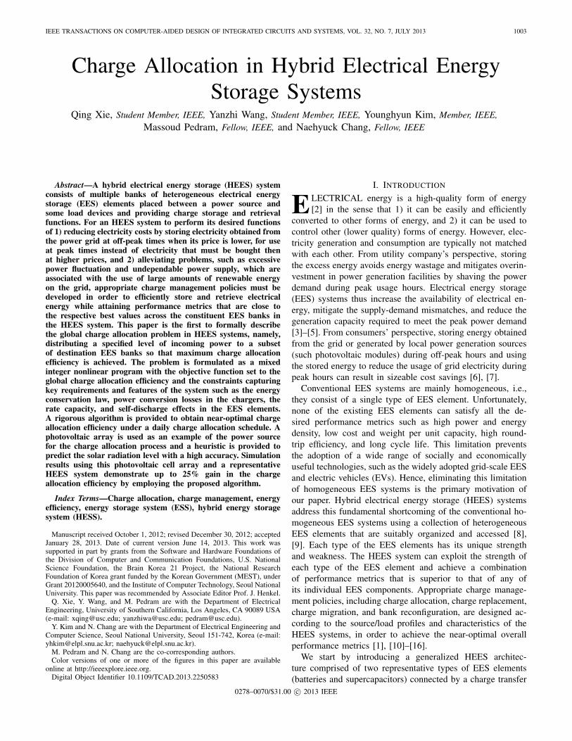
2) Battery Bank: Battery banks have the advantages ofhigh energy capacity and low self-discharge, and therefore,they are suitable for long-term storage purpose. The proposedcharge allocation framework and optimization technique aregeneral and can be applied to any type of battery banks sofar as we have accurate battery models. Intensive work hasbeen conducted to explore accurate and easy-to-use batterymodels. The electrochemistry-based models [27], [28] areaccurate but too complicated to use in system-level designand optimization. We thus rely on a circuit-based batterymodel with good accuracy [29], [30] as we formulate thecharge allocation problem in a mathematical form. Fig. 5demonstrates the model accuracy comparing the measuredLi-ion battery terminal voltage with simulation results fromthe circuit model for a discharging process. We describe thegeneral properties of all the battery banks in this section, andomit the bank index k for notational simplicity.
XIE et al.: CHARGE ALLOCATION IN HYBRID ELECTRICAL ENERGY STORAGE SYSTEMS 1007
Fig. 5. (a) Comparison of the circuit model simulation results with themeasured battery terminal voltage of two serial-connected 350 mAh Li-ionbatteries. (b) Conversion efficiency of an LTM4607 power converter.
Fig. 4 shows a charging process of a Li-ion battery, witha runtime-based model on the left, and a circuit-based modelon the right for accurately capturing of the battery service lifeand the I–V characteristics. In this model, the SoC is given bySoC = Cb
/Cb,full. In practice, ignoring the battery aging, we
derive Cb,full from the nominal capacity (usually characterizedin units of A·h) of the battery. The battery OCV is modeled asa function depending on SoC. Other parameters, such as theinternal resistance and capacitance, are functions of SoC aswell. The functions are nonlinear and involve some empiricalparameters bij [31]
V OC = b11eb12·SoC + b13(SoC)3 + b14(SoC)2 + b15SoC + b16
Rs = b21eb22·SoC + b23, Rts = b31e
b32·SoC + b33
Cts = b41eb42·SoC + b43 Rtl = b51e
b52·SoC + b53
Ctl = b61eb62·SoC + b63. (2)
The rate capacity effect of batteries describes how theavailable charge in a battery relates to the magnitude of thedischarging current [32]. Peukert’s law is an empirical relationthat accurately relates the discharging time and dischargingcurrent to the change of the battery charge. This law isdescribed as �Cb = (Iarray)γd · t, where t is the dischargingtime, and γd is the Peukert constant (1.05 and 1.3 depending onthe battery type). A similar relationship can be approximatelyused for the charging process except that Peukert constant forcharging γc is less than 1. Thus, we have
Ieq = (Iarray)γc
SoC(t) = SoC(0) +∫ t
0
(Ieq(τ) − Isd(τ))
Cb,full· dτ (3)
where Ieq in (3) is the equivalent charging current inside thekth EES array, considering the rate capacity effect. The Ieq
reflects the rate that a battery sends or receives charge. (3)shows that the Iarray is a convex function of Ieq. Typically, Isd
is very small in batteries.The OCV and CCV of a battery are generally not equal to
each other. Fig. 4 shows that the difference between them isthe voltage drop on the internal resistances Rs, Rts, and Rtl
V CC(t) = V OC(t) + Vtl(t) + Vts(t) + Iarray(t) · Rs. (4)
3) Supercapacitor Bank: The supercapacitor is anotherrepresentative EES element that has relatively lower energydensity, but superior cycle efficiency and much longer cyclelife compared to batteries. Thus, the supercapacitor banksare commonly used to deal with the peak power demand or
Fig. 6. Circuit model of the buck–boost converter.
supply. The rate capacity effect is negligible in supercapacitorand we have Iarray ≈ Ieq. The electrical circuit model forthe supercapacitor used in this paper contains a low seriesresistance (∼25 m�) [31]. Therefore, the following relationbetween V OC(t) and V CC(t) holds for the supercapacitors
V CC(t) = V OC(t) + Iarray(t) · Rseries. (5)
A fundamental disadvantage of the supercapacitor is the highself-discharge rate compared with other EES elements. Asupercapacitor typically loses more than 20% of its storedenergy per day due to self-discharge [33]. The voltage decayof a supercapacitor for a short time interval �t is given by
V OC(t + �t) = V OC(t) · e−�t/τ (6)
where τ is the self-discharge time constant. Using Taylorexpansion, the power loss rate due to self-discharge is givenby
Psd(t) = Ccap
(V OC
array(t))2
τ. (7)
4) Charger: We use a pulse width modulation (PWM)buck–boost converter model as the charger model. The inputvoltage, input current, output voltage, and output current ofthe charger are denoted by Vin, Iin, Vout, and Iout, respectively.A charger has two working modes: buck mode (if Vin > Vout)and boost mode otherwise. When the charger is turned ON,the power loss Pc of the charger consists of three components:conduction loss Pcdct, switching loss Psw, and controller lossPctrl. The power loss of the charger is zero when the chargeris turned OFF. Note that Psw and Pctrl are nonzero and notproportional to the output power. We adopt a binary indicationvariable xc such that xc = 1 if the charger is turned ON, andxc = 0 otherwise. Thus, Pc is given by
Pc = Ponc · xc = (Pcdct + Psw + Pctrl) · xc. (8)
Fig. 6 shows a schematic of a PWM buck–boost converter.It consists of four switching MOSFETs whose ON–OFF statesdetermine the operation mode of the converter. The power losscomponents are mainly determined by the PWM duty ratio D
(less than 1), the maximum current ripple �I, the switchingfrequency fs, the controller current Icontroller, the equivalentseries resistances RL and RC, and the turn-on resistance andgate charge of the ith MOSFET switch, Rswi and Qswi. In the

1008 IEEE TRANSACTIONS ON COMPUTER-AIDED DESIGN OF INTEGRATED CIRCUITS AND SYSTEMS, VOL. 32, NO. 7, JULY 2013
buck mode, we adopt the power loss model in [34] as follows:
D =Vout
Vin, �I = Vout
1 − D
Lf · fs
Pcdct = Iout2 · (RL + D · Rsw1 + (1 − D) · Rsw2 + Rsw4)
+(�I)2
12· (RL + D · Rsw1 + (1 − D) · Rsw2 + Rsw4 + RC)
Psw = Vin · fs · (Qsw1 + Qsw2)
Pctrl = Vin · Icontroller. (9)
Note that in (9), the switching loss Psw and controller lossPctrl are independent of Iout. We derive the power loss in boostmode based on the power loss in buck mode
D = 1 − Vin
Vout, �I = Vin
D
Lf · fs
Pcdct =
(Iout
1 − D)2 · (RL + DRsw3 + (1 − D)Rsw4+Rsw1 + D(1 − D)RC)
+(�I)2
12· (RL+D · Rsw3+(1 − D) · Rsw4+Rsw1+(1 − D) · RC)
Psw = Vout · fs · (Qsw3+Qsw4)
Pctrl = Vin · Icontroller. (10)
We extract the model parameters based on LTM4607 [35]converter and compare the simulated and measured conversionefficiency in Fig. 5(a).
5) CTI: We assume that the CTI is an ideal conductor inthis paper. The American wire gauge data show that AWG1 wire has 0.4066 m�/m. As the typical wire length in anHEES system is in order of meters, the resistance is approxi-mately ∼ 1 m�, which is negligible compared to the internalresistance of the EES bank arrays (a single Li-ion batteryusually has internal resistance of 0.1∼0.2 �.) Furthermore,the CTI inductance is even more negligible because the CTIbus voltage changes very slowly. The CTI bus capacitance isorders of magnitude smaller than the bank array capacitance.
B. Charge Allocation Optimization Problem Formulation
In this paper, we target the charge allocation problem ofan HEES system with an energy harvesting system, e.g., aPV module. Fig. 3 shows the diagram of the system. The PVmodule collects the solar energy and delivers the energy tothe HEES system. The charge allocation process starts at timet = 0 and ends at time t = Ta. From the initial SoCs of all EESbanks, we determine the OCV of EES arrays V OC
array,k(0) for allEES banks. We observe the solar radiation levels in the targetarea and based on this predict the power generation profile ofthe PV module over the charge allocation process.
The charge allocation process is managed by three sets ofcontrol variables that should be optimally determined for thehighest global efficiency. The first one is CTI voltage Vcti(t),which is maintained by the source-to-CTI charger. The secondone is the set of selected EES banks, S′(t) ∈ S. The thirdset of variables is {Iarray,k(t)}, k ∈ S of all the EES banks,which are tuned by the EES bank chargers. Note that an arraycharging current can be set to 0, i.e., we turn off the chargerif we decide not to charge that EES bank. The solution of thecharge allocation problem consists of three parts: Vcti(t), S′(t),
and {Iarray,k(t)}, k ∈ S, t ∈ [0, Ta]. We formulate the GCAas a mathematical programming problem, while the objectivefunction is the GCA efficiency and variables are the threevariables aforesaid.
We derive the constraints in the mathematical programmingproblem based on the law of energy conservation. Electricalenergy is generated by PV and delivered to the CTI throughthe source-to-CTI charger, where it is further distributed by se-lected chargers to their corresponding destination EES banks.Based on the law of energy conservation, the power suppliedby the power source Psrc(t) consists of Pc,s(t), Pwaste(t) and thepower delivered to CTI Pcti(t); thus, the energy conservationfor the CTI is given by
Psrc(t) = Vsrc(t) · Isrc(t) = Pc,s(t) + Pcti(t) + Pwaste(t)
= Pc,s(t) + Vcti(t)N∑
k=1
Ibank,k(t) + Pwaste(t). (11)
For the kth charger, the output power equals the input powerminus the power loss during the conversion. Thus, the energyconservation for the charger is given by
Vcti(t) · Ibank,k(t) = V CCarray,k(t) · Iarray,k(t) + Pc,k(t)
= V CCarray,k(t) · (
Ieq,k(t))1/γc +Pc,k(t). (12)
Pc,k(t) and Pc,s(t) in (11) and (12) can be derived using (8)–(10) but with different sets of parameters.
We define the objective function as the GCA efficiency, orequivalently, the total energy gain in all EES banks after thecharge allocation process, i.e., the integration of the powerpushed into all EES banks minus the leakage power as in (7).Continuing the previous analysis, the energy increase rate inthe kth EES bank, denoted by Pgain,k(t), is given by
Pgain,k(t) = VOCarray,k(t) · Ieq,k(t) − Psd,k(t) (13)
d
dtEHEES(t) =
N∑k=1
Pgain,k(t) (14)
where the EHEES(t) is the the total energy stored in all HEESbanks. Note that the first term on the right-hand side (RHS)in (13) corresponds to the power that is pushed into the kthEES bank. Compared to the first term on the RHS in (12), weexclude the power dissipation on the internal resistance of theEES banks and the power loss due to the rate capacity effectfrom the output power of the kth charger.
We formulate the GCA optimization problem as follows.Given: Initial SoCs of all destination EES banks, SoC(t)|t=0,∀k ∈ S; (historic) profile of the solar radiation; specificationsof the HEES system and the PV module; and duration of thecharge allocation process [0, Ta].Find: Vcti(t), S′(t), and Iarray,k(t), ∀k ∈ S and ∀t ∈ [0, Ta].Maximize: the GCA efficiency ηGCA, which is given by
ηGCA =
∑Nk=1
∫ Ta
0 Pgain,k(t)dt∫ Ta
0 Psrc(t)dt(15)
or equivalently maximize the total energy increment in all thedestination EES banks at time Ta, given by the nominator termin (15), since the denominator term in (15) is fixed.

XIE et al.: CHARGE ALLOCATION IN HYBRID ELECTRICAL ENERGY STORAGE SYSTEMS 1009
Subject to: 1) Lower and upper bound of the array chargingcurrents
0 ≤ Ieq,k(t) ≤ Imax,k, ∀t ∈ [0, Ta], ∀k ∈ S. (16)
2) Maximum energy storage constraint
Ek(0) +∫ t
0Pgain,k(τ)dτ ≤ Emax,k, ∀t ∈ [0, Ta] (17)
where Ek(0) stands for the initial energy stored in the kth bankat the beginning of the charge allocation process.3) The conservation of energy given by (11) and (12).4) The conservation of charge given by (3).
Although {Iarray,k(t)} is the set of variables that we cancontrol using the chargers, we use {Ieq,k(t)} as the optimizationvariables instead in the formulation because of the conve-nience in solving the optimization problem. We determine{Iarray,k(t)} from solved {Ieq,k(t)} according to (3). In addition,the GCA optimization problem is an MINLP problem due tothe existence of binary variables {xc,k(t)}. Therefore, the GCAoptimization problem is NP-complete and cannot be optimallysolved in polynomial time. We provide an approximation algo-rithm to obtain the near-optimal solution of the GCA problem.
IV. Methodology
Before solving the GCA problem, we first consider theICA problem, which aims to optimize the charge allocationefficiency at a specific time instance. We present an algorithmto solve the ICA problem and derive a near-optimal solution.Subsequently, we break the whole charge allocation processinto a series of time slots and solve one ICA problem ateach decision epoch. However, a simple combination of theICA solutions at each decision epoch is a greedy decision,which may not achieve the global optima due to the lack ofconsideration of SoC changes in the EES banks, especiallythose banks that have small energy capacity and high chargingefficiency.2 To overcome this issue, we incorporate an upperbound on the total charging power of the high-charging-efficiency banks.
The rest of this section is organized as follows. Wefirst present the heuristic for predicting the solar power inSection IV-A. Then, we elaborate the near-optimal ICA solverand the heuristic for deriving the charging power limits inSections IV-B and IV-C, respectively. Finally, we solve theGCA problem as a time series of solutions to the constrainedICA problems. Table III lists the important notations used inthe following text.
A. Solar Irradiance Level Prediction
Accurate online solar irradiance forecast, which providesthe clue of future power generation, is extremely importantin developing the GCA algorithm since the optimal GCApolicy depends on the power generation profile. We break thedaily observation of solar irradiance level into M time slots
2We classify all EES banks into two groups: high-charging-efficiency banks(e.g., supercapacitor banks) and low-charging-efficiency banks (e.g., batterybanks) according to their properties.
TABLE III
Notation Used in Section IV
Notationdn, tm at the tmth time slot in the dnth dayCs(dn, tm) clear sky solar irradiance level (W/m2)Rs(dn, tm) observed solar irradiance level (W/m2)ξc(dn, tm) climate condition factor, typically less than 1γ(tm) screening factor to judge whether the solar irradiance
is affected by the climate conditionsPds(dn, tm) predicted solar irradiance level (W/m2)P
upSB(tm) upper limit for the charging power of all
supercapacitor banksESB the energy stored in all supercapacitor banksEBB the energy stored in all battery banks
(0, t1, t2, ..., tM). We consider two factors in order to accuratelypredict the solar irradiance: clear sky solar irradiance levelCs(dn, tm) (i.e., solar irradiance in a sunny day), which standsfor the maximum solar irradiance level without any decaydue to the climate conditions, and climate condition factorξc(dn, tm), which takes into account the decay factor causedby climate conditions, such as rain, cloud, and so on. We seteach time slot to be 10–15 min so that the solar irradiance leveland climate conditions are approximately unchanged within atime slot.
We consider that the climate conditions have an approxi-mately linear decaying effect on the solar irradiance levels.To obtain the predicted solar irradiance level Pds(dn, tm), wemultiply the climate condition factor at previous time instanceξc(dn, tm−1) to Cs(dn, tm). At the end of the tmth time instance,we observe the solar irradiance level Rs(dn, tm) and calculateξc(dn, tm) as relative ratio between Rs(dn, tm) and Cs(dn, tm)
Pds(dn, tm) = Cs(dn, tm) · ξc(dn, tm−1)
ξc(dn, tm) =Rs(dn, tm)
Cs(dn, tm). (18)
Although Cs(dn, tm) varies with the location on the earthand the time of the year, it is predictable based on theobservation history of solar irradiance levels [36]. We adoptexponential smoothing, which is a powerful technique thatis applied to sequential data to make forecasts by assigningexponentially decreasing weights over time [6]. This weightingmethod makes exponential smoothing particularly effectivein our problem since Cs(dn, tm) is more related to the solarirradiance in recent past rather than earlier past. We observeRs(dn, tm) and update Cs(dn, tm) using a smoothing factor α,which ranges between 0 and 1. The Cs(dn, tm) is given by
Cs(d1, tm) = 0,
Cs(dn+1, tm) = Cs(dn, tm), if Rs(dn, tm) < λ(tm)Cs(dn, tm)
Cs(dn+1, tm) = α · Cs(dn, tm)+(1−α) · Rs(dn, tm), otherwise.
(19)
Since Cs(dn, tm) denotes the clear sky solar irradiance level,we use λ(tm) as a screening factor to prune the solar irradiancedata that severely degrade due to the climate conditions in (19)and only update Cs(dn, tm) using those data that are collectedin sunny days. More precisely, if Rs(dn, tm) < λ(tm)·Cs(dn, tm),we consider it to be not under clear sky condition, andthereby directly carry Cs(dn, tm) to the next time instance.We determine λ(tm) based on an online learning approach,

1010 IEEE TRANSACTIONS ON COMPUTER-AIDED DESIGN OF INTEGRATED CIRCUITS AND SYSTEMS, VOL. 32, NO. 7, JULY 2013
where the state set is defined as the set of time slots {tm}, theaction set is defined as a set of different reasonable screeningfactors (λ1, λ2, ..., λK) (i.e., 0.7–1). Selecting different λk endsup with different Cs(dn+1, tm) and in turn affects the predictionslater on. The prediction error is captured by the penaltyfunction Errorm. We adopt Q-learning and update the state–action pair Q(tm, λk) using a learning rate β
Errorm = |Pds(dn, tm) − Rs(dn, tm)|Q(tm, λk) ← (1 − β) · Q(tm, λk) + β · Errorm. (20)
We pick the screening factor λk according to the probability
ofexp(−Q(tm, λk))∑Kk=1 exp(−Q(tm, λk))
.
B. ICA Solver
The ICA optimization problem maximizes the total powerthat is pushed into all EES banks at a specific time instance.The ICA problem is a special case of the GCA problem whenTa → 0. The control variables to be solved in the ICA problemare similar to GCA problem, except that they are only for onetime instance. Thus, we omit t for simplicity in writing. Wedefine the objective function ICA efficiency ηICA as
ηICA =1
Psrc
N∑k=1
Pgain,k (21)
where the Psrc is a fixed value and do not affect the optimiza-tion. We apply similar constraints (11) and (12) to the ICAproblem. Therefore, the ICA optimization problem is again anMINLP problem. We utilize three facts to simplify the orig-inal ICA problem to optimal charging current determination(OCCD) problem, which is a convex optimization problem.The three facts are as follows.
1) The optimal ICA efficiency ηICA is approximately an uni-modal function with respect to the CTI voltage Vcti. Therefore,we perform a ternary search3 in the feasible region of Vcti asthe outer loop. Inside the outer loop, we consider the CTIvoltage Vcti as a fixed value and solve the OCCD problem.More precisely, we do not treat Vcti as an variable in OCCDproblem; otherwise, solving the {Ieq,k} becomes impracticalbecause the power loss in the charger (8)–(10) is a functionof both {Ieq,k} and the CTI voltage.
2) It will be beneficial to turn off some EES banks if theiroptimal {Ieq,k} are smaller than a threshold value Ith. Thecharger power loss contains a fixed part and a part proportionalto the output charging current. It is not worthwhile to keep thecharger ON when the output charging current is small. Thebinary indicators {xc,k} that denote the charger status lead tothe discontinuity in optimization problem. To overcome thisissue, we maintain a selection set S′, which is a subset of S,and only consider Ieq,k, k ∈ S′ in the OCCD problem, i.e.,xc,k = 1, k ∈ S′. For other EES banks that are not in S′, weset Ieq,k = 0, xc,k = 0, k /∈ S′. In this way, the OCCD problembecomes a continuous mathematical programming problem.
3A ternary search is a divide and conquer-based algorithm that determineseither that the minimum or maximum cannot be in the first third of thedomain or that it cannot be in the last third of the domain, then repeatson the remaining two-thirds.
Algorithm 1: ICA solver (ICAS)Input: The initial SoCk, ∀k ∈ S, the input power Psrc and Vsrc, the feasible region
of CTI voltage (Vcti,min, Vcti,max), and predefined parameters ε, Ith , �Vth .Determine the OCVs V OC
array,k , ∀k ∈ S based on SoCs;1repeat2
for V(1)cti = 1
3 Vcti,min + 23 Vcti, max , and V
(2)cti = 2
3 Vcti, min + 13 Vcti,max , do3
i ← 0;4Initialize S′ (0) ← S;5Initialize V
CC,(0)array,k ← V OC
array,k , ∀k ∈ S′ (0);6repeat7
i ← i + 1, S′ (i) ← S′ (i−1);8Solve the OCCD problem with fixed Vcti , S′ (i−1) and V
CC,(i−1)array,k ,9
∀k ∈ S′ (i−1), find the optimal {I(i)eq,k, k ∈ S′ (i−1)};
∀k ∈ S′ (i−1), if I(i)eq,k < Ith , then10
I(i)eq, k ← 0 and S′ (i) ← S′ (i)\k11
Calculate {I(i)array,k , update V
CC, (i)array,k , ∀k ∈ S′ (i) using (3)–(5)12
until maxk∈S′ (i)
∣∣V CC, (i)
array,k − VCC,(i−1)array,k
∣∣ < ε and S′ (i) = S′ (i−1) ;13
Calculate ηICA(Vcti), using (21);14
if ηICA(V
(1)cti
)< ηICA
(V
(2)cti
), then15
Vcti,min ← 13 Vcti,min + 2
3 Vcti,max16
else17Vcti,max ← 2
3 Vcti,min + 13 · Vcti,max18
until |Vcti,max − Vcti,min| < �Vth ;19Vcti ← 1
2 (Vcti,min + Vcti,max)20return Vcti , S′ (i), and I
(i)eq,k , ∀k ∈ S21
For each fixed Vcti, we first initialize S′ to be the full set ofall EES banks and remove those EES banks whose Ieq,k issmaller than Ith. We repeat solving the OCCD problem untilthe selection set S′ converge.
3) In general, the CCVs are not very different from OCVssince the internal resistances are not large, according to (4) and(5). The objective function is a complicated nonlinear functionof {Ieq,k} since both the CCVs and {Iarray,k} are involved inthe charger’s power loss. To address this issue, we use fixedCCVs {VCC
array,k} in the OCCD problem instead of functions of{Iarray,k}. After solving the OCCD, we obtain the {Ieq,k} andupdate VCC
array,k using (3)–(5). We repeat solving the OCCDproblem until the VCC
array,k, ∀k ∈ S′ converge.The proposed ICAS algorithm is summarized in
Algorithm 1. We do ternary search of Vcti in the outerloop, while in the inner loop, we solve the OCCD problemrepeatedly at a fixed Vcti and update the selection set S′ aswell as the CCV voltages {V CC
array,k}. The OCCD problem hasa concave objective function (21) to be maximized, subjectingto linear inequality constraints (16) and convex inequalityconstraints (11) and (12). Thus, the OCCD problem is aconvex optimization problem and can be solved optimallyin polynomial time using the standard convex optimizationtechnique. We carefully set the threshold current Ith suchthat turning OFF the charger when the Ieq,k < Ith alwaysimproves the charge allocation efficiency. Fig. 5(b) shows thatwhen Ieq,k < 0.05 A, the conversion efficiency of the chargerbecomes unacceptably low. Thus, we set Ith to be 0.05 A.The inner loop in Algorithm 1 is terminated when S′ and{V CC
array,k} converge, where the optimal ηICA at a specific Vcti
is achieved. We search the Vcti domain and repeat the innerloop subroutine for different Vcti until a termination conditionis met, i.e., the difference between the upper and lowerbounds of the Vcti domain falls within a predefined threshold�Vth.

XIE et al.: CHARGE ALLOCATION IN HYBRID ELECTRICAL ENERGY STORAGE SYSTEMS 1011
Fig. 7. Comparison of ICA efficiency ηICA at different CTI voltages Vctiobtained by the proposed method (solid curve) and MC simulation (crossmarks).
Fig. 7 shows ηICA versus the Vcti for a four-bank HEESsystem. The solid curve shows that the ηICA solved at eachfixed Vcti is an unimodal function of Vcti. Thus, we convergeto the near-optimal solution (displayed as a circle) by ternarysearching the Vcti domain. The empty space in Fig. 7 belowthe solid curved is caused by the discontinuity of the {xc,k}.The Monte Carlo (MC) simulation results (displayed as crossmarks) shows that the proposed method always achieves bettersolutions than the MC simulation.
C. Power Limit Derivation
The ICAS algorithm presented in Section IV-B solves theICA problems near-optimally and returns the correspondingEES bank selection, CTI voltage, and EES array chargingcurrents. A straightforward way to solve the GCA problemis to follow a greedy approach, i.e., breaking the wholecharge allocation process into a series of consecutive timeslots (0, t1, t2, ..., tM) and solving an ICA problem at thebeginning of each time slot, with the approximation that theSoC stays unchanged over the time slot. However, such angreedy approach does not consider the EES bank capacity,and thereby may not lead to the optimal results, e.g., simplyassigning a large amount of power to high-charging-efficiencybanks. As shown in Fig. 1, supercapacitor banks usuallyhave high charging efficiency thanks to their high powercapacity and small internal resistance, while their energycapacity is very limited. Therefore, the greedy GCA approachmay fully charge the supercapacitor banks very quickly andthen assign all power to battery banks during the rest ofthe charge allocation process. In such a case, the GCAefficiency may be unacceptably low due to the following tworeasons.
1) The power loss due to the rate capacity effect in thebattery banks increases superlinearly as the array chargingcurrent increases, according to Peukert’s law. The greedyapproach may charge the battery banks with high rates afterall supercapacitor banks are full. Thus, the HEES systemsuffers a significant power loss that prevents it from reachingthe global optimality.
2) The other reason that makes the greedy approach evenworse is the self-discharge of the supercapacitor banks. Theself-discharge power rate grows quadratically as the OCV ofthe supercapacitor bank increases, according to (7). Thus, thehigh leakage rate degrades the GCA efficiency if we chargethe supercapacitor banks quickly and leave them at high SoCstate for the rest of charge allocation process.
Due to these reasons, we modify the original ICAS to makeit aware of the future energy generation. More precisely, weimpose an upper limit for the total charging power of all thesupercapacitor banks, P
upSB(tm), to prevent rapid charging of
supercapacitor banks, leaving some capacity for the remainingcharge allocation process to combat the rate capacity effect andalleviate the power loss due to the self-discharge. A low powerlimit may undercharge the supercapacitor banks and result inlow GCA efficiency, since the supercapacitor banks typicallyhave high charging efficiency. Furthermore, the power limitshould also consider the power generation. For example, thepower limit should be relatively high during the peak period ofthe power supply in order to allow more power to be assignedto the supercapacitor banks. An effective heuristic of settingthe appropriate power limits to achieve the near-optimal GCAefficiency is to charge the supercapacitor banks such that theyare fully charged at the end of the charge allocation process.
Since supercapacitor banks typically have higher chargingefficiency, the ICAS intends to assign full P
upSB(tm) amount
of power to them. Therefore, the energy assigned to allsupercapacitor banks (ESB) and battery banks (EBB) over thewhole charge allocation process are approximately given by
ESB =M∑
m=1
∫ tm
tm−1
PupSB(tm)dt,
EBB =M∑
m=1
∫ tm
tm−1
(Psrc(tm) − P
upSB(tm)
)dt. (22)
According to (6) and (7), we conclude that the ratio betweenenergy loss due to self-discharge and the total energy is fixedand given by μsd = ESB(t + �t)/ESB(t) = e−2�t/τ , where �t isthe duration of a time slot and μsd < 1 is the ratio of remainingenergy after one time slot. Therefore, the total energy loss dueto the self-discharge Esd is approximately given by
Esd = ESB −M∑
m=1
∫ tm
tm−1
(1 − μsd)(M−m+1)PupSB(tm)dt. (23)
We denote the part of the energy assigned to all the batterybanks but wasted due to the rate capacity effect by Erb. Forderivation simplicity, we approximately treat all battery banksas a big equivalent battery with an equivalent Peukert constantγeq < 1. Thus, Erb is given by
Erb = EBB −M∑
m=1
∫ tm
tm−1
(Psrc(tm) − P
upSB(tm)
)γeqdt. (24)
We determine the parameter γeq in (24) by fitting the energyloss due to rate capacity effect of all battery banks. Thepower limit is constrained by the energy capacity of all thesupercapacitor banks. This helps us to express the energy lossdue to the self-discharge and rate capacity effect as convexfunctions of {Pup
SB(tm)}. The derivation of power limit becomesan optimization problem as follows:
Minimize: Erb + Esd, (25)
Subject to: maximum energy constraint for SB,M∑
m=1
∫ tm
tm−1
PupSB(tm)dt ≤ 1
2
∑k∈SB
Ccap,k · (V 2max,k − (V OC
array,k)2) (26)

1012 IEEE TRANSACTIONS ON COMPUTER-AIDED DESIGN OF INTEGRATED CIRCUITS AND SYSTEMS, VOL. 32, NO. 7, JULY 2013
where Vmax,k is the maximum voltage of the supercapacitorbank and V OC
array,k is the current OCVs. Equation (25) is aconvex function and (26) is a linear constraint. Thus, we solvethe optimization problem (25) using Lagrange multiplier andachieve the optimal set of {Pup
SB(tm)} over all time slots. Thesource power information that is required in (22)–(25) comesfrom the solar irradiance level prediction in Section IV-A. Thepower upper limit may change due to the variation of theclimate condition. We determine this limit at every time slotaccording to the latest information of climate conditions andremaining capacity of the supercapacitor banks.
D. GCA Solver
In this section, we present the GCA solver with chargingpower limits (SCPL) for the GCA problem, integrating so-lar irradiance level prediction, power limits derivation, andmodified ICAS alternately. The original ICAS finds the near-optimal solution of the ICA problem by iteratively solvingOCCD problem and updating the CCVs and EES banksselection set. We modify the original ICA problem to con-strained ICA problem by introducing a new constraint for thesupercapacitor banks as follows:
Vcti(t) ·∑k∈SB
Ibank,k(t) ≤ PupSB(tm), ∀t ∈ [tm−1, tm]. (27)
Since (27) is a convex inequality constraint, the OCCD inconstrained ICA problem is still a convex optimization prob-lem. We propose the SCPL algorithm as follows. We firstbreak the whole charge allocation process into a series of shorttime slots (0, t1, t2, ..., tM). For each time slot, we observe thecurrent solar irradiance level, make prediction of the solarirradiance level over the rest time of the day, derive thepower upper limits for the supercapacitor banks, and solve theconstrained ICA problem. The SCPL algorithm is summarizedas Algorithm 2. The SCPL algorithm solves the GCA problemsand derives the CTI voltage setting Vcti(t), selected set of theEES banks S′(t), and the array charging currents {Iarray,k(t)}for the selected EES banks over the whole charge allocationprocess. Our claim that the proposed algorithm returns a near-optimal solution of the GCA problem is based on the aboveflow in which each subproblem is solved near-optimally.
E. Temperature, Aging, and Malfunction Handling
The optimal management policy of the HEES should ac-count for the effect of temperature. Intensive research hasbeen conducted to study the battery behaviors at varioustemperatures. It turns that the cycling capacity, i.e., batterycharge Cb,full, only varies slightly (less than 5%) from 25 °Cto 60 °C [37], [38]. The internal resistance of the battery doesnot vary much (∼ 10%) either with the temperature rising [37].Therefore, we ignore the temperature effect in the proposedSCPL algorithm. The GCA problem only solves the allocationproblem for one charging process and does not involve cycling.
The batteries age as the HEES system is being operated,which causes capacity fading and the increase of internalresistance. Some known factors, such as the depth of dischargeand average SoC significantly affect the battery aging. Thus,
Algorithm 2: GCA solver with charging power limits(SCPL)
Input: The specifications of the HEES system and PV module; initial SoCk,∀k ∈ S; duration of charge allocation process [0, Ta] on the dnth day;observation history of previous solar irradiance level, Cs(dn−1, tm),m ∈ [1, 2, ..., M].
Break [0, Ta] into M time slots (0, t1, t2, ..., tM );1for (m ← 1;m ≤ M; m + +) do2
Observe Rs(dn, tm);3Update Cs(dn, tm) using (19) and (20);4Calculate ξc(dn, tm) ← Rs (dn,tm )
Cs (dn,tm )5Predict Pds(dn, tk), ∀k > m, using (18);6Calculate the remaining capacity in supercapacitor banks;7Derive the P
upSB(tm) according to remaining capacity in supercapacitor banks8
and Pds(dn, tk), m < k ≤ M, using (22)–(25);Perform modified ICAS with power limit P
upSB(tm) and find Vcti(t), S′(t), and9
Ieq,k(t), ∀k ∈ S, t ∈ [tm−1, tm];Calculate Iarray,k(t) based on Ieq,k(t), ∀k ∈ S;10Update SoCs and OCVs of all EES banks, using (2) and (3);11
return Vcti(t), S′(t), and Iarray,k(t), ∀k ∈ S, t ∈ [0, Ta]12
we perform Coulomb counting for each EES bank, calculatethe state of health (SoH) degradation, and update modelparameters according to the SoH degradation. In fact, a hightemperature significantly speeds up the battery aging. Werecord the battery temperature so that we can accurately updatethe characteristics of the aged battery including the batterycapacity and internal resistances [39], [40].
In practice, a part of EES elements may have malfunctionduring runtime. We address this issue at the bank level andsystem level. A more elaborated dynamic bank reconfiguration[11] improves fine-granularity fault tolerance of the EESbank, which is a bank-level method. We simply exclude theunavailable banks from the set of available EES banks at thesystem level. We update bank set S at the beginning of eachdecision epoch and perform the proposed method because theGCA problem is solved in a discrete time manner.
V. Simulation Results
We consider two different HEES systems: one consists offour EES banks (two supercapacitor banks and two batterybanks), and the other consists of eight EES banks (foursupercapacitor banks and four battery banks.) We use the solarirradiance level data that are collected in Los Angeles for year2011 [25] and use PV modules with MPTT technique [24] asthe power source. We consider the charge allocation processlasting for 12 h and solve corresponding GCA problems usingthe proposed GCA algorithm for both HEES systems. Weextract the model parameters of chargers, Li-ion batteries,and supercapacitors through real measurements based on theLinear Technology LTM4607 converter [35], the GP1051L35Li-ion battery cells [41], and the Maxwell BCAP P270 seriessupercapacitor [42].
The baseline setups in the simulation include: 1) unbiasedbank charging (UB), the input power is uniformly allocatedinto all EES banks; 2) battery banks first policy (BBF),the input power is allocated into all battery banks; and 3)supercapacitor banks first scheme (SBF), the input poweris allocated into all supercapacitor banks. The BBF policyignores the supercapacitor banks and is used to mimic thehomogeneous battery-only EES systems. Note that the SBFpolicy switches to BBF if all supercapacitor banks are fully
XIE et al.: CHARGE ALLOCATION IN HYBRID ELECTRICAL ENERGY STORAGE SYSTEMS 1013
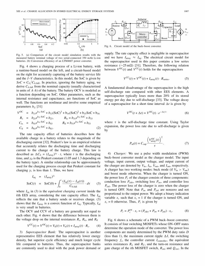
Fig. 8. Outcomes of the proposed solar irradiance level predictor at 8 AM,10 AM, and 12 AM. The four groups from top to bottom are the averagesolar irradiance levels for July, April, September, and December, respectively.
Fig. 9. Comparisons of the GCA with the proposed solar prediction methodand Oracle system for (a) four-bank HEES system and (b) eight-bank HEESsystem.
charged. We use a constant CTI voltage for the baseline setupsduring the whole charge allocation process. We operate thebaseline systems at several representative CTI voltage valuesand compare the results with that of the proposed SCPLalgorithm. We investigate different solar irradiance levels in ayear (April, July, September, and December) and PV moduleconfigurations4 (4×2, 2×4, 4×4, 4×6 for four-bank HEESsystem and 4 × 2, 4 × 4, 4 × 6, 6 × 6 for eight-bank HEESsystem), with 16 test cases in total for each HEES system.
A. Solar Irradiance Level Prediction
Fig. 8 shows the monthly average solar irradiance levelprediction using the proposed online prediction method atthree time instances: 8 AM, 10 AM, and 12 AM in April,July, September, and December. We predict the solar irradiancelevel for the remaining charge allocation process at each timeinstance. The average error of the proposed prediction heuristicis less than 10%.
Fig. 9 compares the total energy gain in HEES systemsfor all the 16 test cases between the SCPL algorithm using
4For a PV module with configuration of n×m, n and m denote the numberof series- and parallel-connected PV cells, respectively.
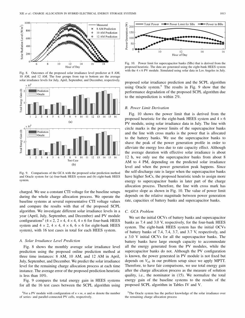
Fig. 10. Power limit for supercapacitor banks (SBs) that is derived from theproposed heuristic. The data are generated using the eight-bank HEES systemwith the 4×6 PV module. Simulated using solar data in Los Angeles in July.
proposed solar irradiance prediction and the SCPL algorithmusing Oracle system.5 The results in Fig. 9 show that theperformance degradation of the proposed SCPL algorithm dueto the misprediction is within 2%.
B. Power Limit Derivation
Fig. 10 shows the power limit that is derived from theproposed heuristic for the eight-bank HEES system and 4 × 6PV module, using solar irradiance data in July. The line withcircle marks is the power limits of the supercapacitor banksand the line with cross marks is the power that is allocatedto the battery banks. We use the supercapacitor banks toshave the peak of the power generation profile in order toalleviate the energy loss due to rate capacity effect. Althoughthe average duration with effective solar irradiance is about12 h, we only use the supercapacitor banks from about 8AM to 4 PM, depending on the predicted solar irradiancelevel and when the power generation peak happens. Sincethe self-discharge rate is larger when the supercapacitor bankshave higher SoCs, the proposed heuristic tends to assign moreenergy to supercapacitor banks in later part of the chargeallocation process. Therefore, the line with cross mark hasnegative slope as shown in Fig. 10. The value of power limitdepends on the relative magnitude between power generationrate, capacities of battery banks and supercapacitor banks.
C. GCA Problem
We set the initial OCVs of battery banks and supercapacitorbanks as 7.4 and 3.0 V, respectively, for the four-bank HEESsystem. The eight-bank HEES system has the initial OCVsof battery banks of 7.4, 7.4, 3.7, and 3.7 V, respectively, anda 3.0 V initial OCVs for all the supercapacitor banks. Thebattery banks have large enough capacity to accommodateall the energy generated from the PV modules, while thesupercapacitor banks do not. Although the PV configurationis known, the power generated in PV module is not fixed butdepends on Vcti in our problem setup since we apply MPTT.Therefore, to have fair comparisons, we use total energy gainafter the charge allocation process as the measure of solutionquality, i.e., the nominator in (15). We normalize the totalenergy gain of the baseline systems to the results of theproposed SCPL algorithm in Tables IV and V.
5The Oracle system has the perfect knowledge of the solar irradiance overthe remaining charge allocation process

1014 IEEE TRANSACTIONS ON COMPUTER-AIDED DESIGN OF INTEGRATED CIRCUITS AND SYSTEMS, VOL. 32, NO. 7, JULY 2013
TABLE IV
Comparison of Normalized GCA Results After a 12 h Charge Allocation Process for the Four-Bank HEES System
BaselineCase n × m Month SCPL UB SBF BBF
5 V 8 V 12 V 5 V 8 V 12 V 5 V 8 V 12 V1 Apr 100.0% 84.7% 89.3% 88.5% 82.1% 92.1% 95.7% 65.0% 68.7% 68.4%2 Jul 100.0% 83.1% 88.7% 88.8% 80.8% 91.9% 95.0% 61.6% 65.9% 65.8%3 4 × 2 Sep 100.0% 87.9% 91.8% 90.1% 85.1% 94.3% 97.1% 69.8% 73.2% 72.6%4 Dec 100.0% 92.8% 94.4% 89.9% 89.9% 96.7% 96.9% 79.1% 81.4% 80.0%5 Apr 100.0% 87.5% 92.3% 89.1% 84.9% 95.2% 96.3% 67.1% 71.0% 69.4%6 Jul 100.0% 85.6% 91.4% 88.9% 83.3% 94.4% 95.6% 63.4% 67.8% 66.4%7 2 × 4 Sep 100.0% 89.3% 93.3% 89.3% 86.4% 95.8% 96.3% 70.8% 74.3% 72.5%8 Dec 100.0% 93.6% 95.3% 88.9% 90.6% 97.7% 96.0% 79.7% 82.0% 79.5%9 Apr 100.0% 82.8% 92.4% 95.1% 74.7% 83.5% 86.5% 53.8% 61.2% 60.4%10 Jul 100.0% 85.4% 96.4% 98.5% 71.8% 81.4% 83.8% 53.6% 62.0% 61.3%11 4 × 4 Sep 100.0% 82.0% 90.3% 92.3% 77.9% 86.4% 88.2% 55.1% 61.7% 61.1%12 Dec 100.0% 81.7% 87.4% 87.4% 80.3% 91.5% 95.9% 58.7% 63.0% 63.0%13 Apr 100.0% 88.1% 95.8% 97.3% 71.1% 81.6% 82.5% 52.3% 61.5% 61.5%14 Jul 100.0% 86.7% 94.7% 96.6% 69.2% 79.4% 82.3% 53.2% 63.2% 63.8%15 4 × 6 Sep 100.0% 86.0% 96.6% 98.8% 72.6% 82.5% 85.4% 52.4% 60.9% 60.5%16 Dec 100.0% 78.6% 87.0% 89.0% 77.9% 87.1% 89.4% 51.2% 57.7% 57.0%
TABLE V
Comparison of Normalized GCA Results After a 12 h Charge Allocation Process for the Eight-Bank HEES System
BaselineCase n × m Month SCPL UB SBF BBF
5 V 8 V 12 V 5 V 8 V 12 V 5 V 8 V 12 V1 Apr 100.0% 91.0% 92.7% 86.9% 88.5% 95.5% 95.6% 83.7% 86.1% 84.3%2 Jul 100.0% 90.1% 93.1% 88.8% 86.6% 94.9% 96.2% 80.5% 83.1% 81.9%3 4 × 2 Sep 100.0% 91.5% 92.1% 84.5% 89.7% 95.8% 94.7% 87.1% 88.8% 86.3%4 Dec 100.0% 92.1% 88.5% 76.3% 92.9% 96.0% 91.2% 93.7% 93.8% 89.1%5 Apr 100.0% 82.3% 88.7% 88.8% 79.3% 91.4% 96.1% 63.9% 68.6% 68.8%6 Jul 100.0% 80.4% 87.9% 89.0% 78.2% 91.1% 95.9% 60.5% 65.7% 66.2%7 4 × 4 Sep 100.0% 84.5% 90.1% 89.2% 81.6% 92.4% 96.2% 67.8% 72.1% 72.0%8 Dec 100.0% 88.9% 92.1% 88.1% 86.0% 94.3% 95.2% 76.3% 79.5% 78.6%9 Apr 100.0% 79.1% 88.4% 90.9% 77.4% 87.8% 91.5% 56.0% 62.1% 62.8%
10 Jul 100.0% 78.2% 88.8% 92.3% 73.4% 79.7% 81.7% 53.7% 61.3% 61.3%11 4 × 6 Sep 100.0% 79.1% 87.2% 88.9% 77.4% 90.4% 95.2% 57.8% 63.3% 63.9%12 Dec 100.0% 84.4% 90.3% 89.6% 81.9% 93.2% 96.9% 65.8% 70.3% 70.4%13 Apr 100.0% 79.3% 92.2% 97.2% 71.0% 81.2% 84.3% 51.3% 60.1% 60.1%14 Jul 100.0% 82.0% 94.6% 97.7% 68.4% 82.3% 85.4% 51.4% 61.1% 61.4%15 6 × 6 Sep 100.0% 77.9% 89.3% 93.3% 73.0% 83.4% 87.1% 51.9% 60.3% 59.9%16 Dec 100.0% 77.7% 86.1% 87.9% 76.6% 90.7% 97.3% 55.2% 60.7% 61.5%
Tables IV and V summarize the GCA results of the pro-posed SCPL algorithm and the selected baseline systems.The proposed SCPL algorithm consistently outperforms thebaseline systems by approximately 5% to 25% in general.Most importantly, the HEES system using the proposed SCPLalgorithm improves the energy harvesting ability by up to 48%compared to the BBF policy, which ignores the supercapacitorbanks. This explains the poor performance of a homogeneousEES system of the same battery banks.
Tables IV and V show that the SBF policy generallyperforms well with a smaller number of PV modules, e.g.,configuration of 4×2 or 2×4, or lower solar irradiance level,e.g., in December. In this case, the supercapacitor banks haveenough capacity to accommodate all energy generated bythe PV modules. Hence, the SBF policy takes the advantageof the high charging efficiency of the supercapacitor banks.However, SBF policy suffers from serious performancedegradation later on after the supercapacitor banks are fullycharged, as shown in the test cases for April and July with4 × 6 or 6 × 6 PV modules. In contrast, UB policy achievesgood results for those test cases with large amount of energygeneration because it unbiasedly allocates generated energyto all EES banks. The performance of UB policy is quiteclose to the proposed SCPL algorithm in some corner casesbecause even the best energy allocation does not help muchwhen the energy generation rate is too high. However, in
general, the proposed SCPL algorithm outperforms UB policyby fully utilizing the high-efficiency EES banks.
Since the optimal Vcti depends on the energy generationprofile, charge allocation policy, SoCs, and properties of EESbanks, there is no way to determine a generally optimal Vcti.We observe a fluctuation of the total energy gain up to 20.7%in case of the different Vcti settings in Tables IV and V. Hence,it is not surprising that an inappropriate Vcti can be often usedin practice unless the proposed concept is widely accepted. Incontrast, the proposed SCPL algorithm searches and convergesrapidly to the optimal Vcti.
Fig. 11(a) shows the total instantaneous power gain of allthe EES banks in the eight-bank HEES system during the 12h charge allocation process. The SBF policy performs well atthe beginning but suffers from a huge performance degradationafter all supercapacitor banks are fully charged. Fig. 11(b) and(c) shows that the average array charging currents of superca-pacitor banks drop to zero and the currents of battery banksjump high at 1 PM. The SBF policy harvests less energy thanBBF policy afterward due to higher self-discharge from thefully charged supercapacitor banks. The UB and BBF policiesallocate charging power uniformly to all the EES banks asshown in Fig. 8. The proposed SCPL algorithm activates thesupercapacitor banks at 7 AM according to the solar irradiancelevel and fully charges the supercapacitor banks at 4 PM.Fig. 11(a) shows that SCPL algorithm outperforms the other

XIE et al.: CHARGE ALLOCATION IN HYBRID ELECTRICAL ENERGY STORAGE SYSTEMS 1015
Fig. 11. Comparison of (a) total power gain, (b) average array chargingcurrent of supercapacitor banks, and (c) battery banks in the eight-bank HEESsystem with the 4 × 6 PV module. Simulated using solar data in Los Angelesin July.
baseline systems by properly allocating charging power anddetermining the CTI voltage.
VI. Conclusion
The HEES system is one of the most promising and practicalways to achieve a high-performance and low-cost EES system.This was the first paper that introduces fundamental conceptsof GCA, including the system architecture and formal problemdefinition. The GCA problem was formulated as a mixed-integer nonlinear optimization problem. We proposed a sys-tematic algorithm for the GCA problem by solving a series ofconstrained ICA at each decision epochs with time-dependentpower limits to avoid the greedy decisions. Furthermore, weproposed an effective way to solve the ICA problem andachieve a near-optimal solution in an iterative manner. In eachiteration, we solved a standard convex optimization problem inpolynomial time. We performed simulations for HEES systemsusing PV modules as the power source and demonstratedthat the proposed algorithm generally improves the energyharvesting ability by 5% to 25% against the baseline setups.
References
[1] Q. Xie, Y. Wang, Y. Kim, N. Chang, and M. Pedram, “Charge allocation for hybridelectrical energy storage systems,” in Proc. Int. Conf. Hardware/Softw. CodesignSyst. Synthesis, 2011, pp. 277–284.
[2] H. T. Odum, “Energy quality and carrying capacity of the earth,” Tropical Ecol.,vol. 16, no. 1, pp. 1–8, 1975.
[3] J. Baker and A. Collinson, “Electrical energy storage at the turn of the millennium,”Power Eng. J., vol. 13, no. 3, pp. 107–112, Jun. 1999.
[4] T. Moore and J. Douglas, “Energy storage, big opportunities on a smaller scale,”EPRI J., pp. 16–23, Spring. 2006.
[5] D. H. Doughty, P. C. Butler, A. A. Akhil, N. H. Clark, and J. D. Boyes, “Batteriesfor large-scale stationary electrical energy storage,” Elecrochem. Soc. Interface,vol. 19, no. 3, pp. 49–53, 2010.
[6] Y. Wang, S. Yue, L. Kerofsky, N. Chang, and M. Pedram, “A hierarchical controlalgorithm for managing electrical energy storage systems in homes equipped withPV power generation,” in Proc. IEEE Green Technol. Conf., Apr. 2012, pp. 1–6.
[7] I. Koutsopoulos, V. Hatzi, and L. Tassiulas, “Optimal energy storage controlpolicies for the smart power grid,” in Proc. IEEE Int. Conf. Smart Grid Commun.,Oct. 2011, pp. 475–480.
[8] M. Pedram, N. Chang, Y. Kim, and Y. Wang, “Hybrid electrical energy storagesystems,” in Proc. 16th ACM/IEEE Int. Symp. Low Power Electron. Des., Aug.2010, pp. 363–368.
[9] F. Koushanfar, “Hierarchical hybrid power supply networks,” in Proc. 47thACM/IEEE Des. Autom. Conf., Jun. 2010, pp. 629–630.
[10] Y. Wang, Q. Xie, Y. Kim, N. Chang, and M. Pedram, “Charge migration effciencyoptimization in hybrid electrical energy storage (HEES) systems,” in Proc. Int.Symp. Low Power Electron. Des., Aug. 2011, pp. 103–108.
[11] Y. Kim, S. Park, Y. Wang, Q. Xie, N. Chang, M. Poncino, and M. Pedram,“Balanced reconfiguration of storage banks in a hybrid electrical energy storagesystem,” in Proc. IEEE/ACM Int. Conf. Comput.-Aided Des., Nov. 2011, pp. 624–631.
[12] Q. Xie, Y. Wang, Y. Kim, D. Shin, N. Chang, and M. Pedram, “Charge replacementin hybrid electrical energy storage systems,” in Proc. 17th Asia South Pacific Des.Autom. Conf., Jan.–Feb. 2012, pp. 627–632.
[13] Y. Wang, Q. Xie, M. Pedram, Y. Kim, N. Chang, and M. Poncino, “Multiple-sourceand multiple-destination charge migration in hybrid electrical energy storagesystems,” in Proc. Des., Autom Test Eur. Conf. Exhib., Mar. 2012, pp. 169–174.
[14] Q. Xie, X. Lin, Y. Wang, M. Pedram, D. Shin, and N. Chang, “State of healthaware charge management in hybrid electrical energy storage systems,” in Proc.Des., Autom Test Eur. Conf. Exhib., Mar. 2012, pp. 1060–1065.
[15] Y. Kim, S. Park, N. Chang, Q. Xie, Y. Wang, and M. Pedram, “Networked archi-tecture for hybrid electrical energy storage systems,” in Proc. ACM/EDAC/IEEEDes. Autom Conf., Jun. 2012, pp. 522–528.
[16] Q. Xie, D. Zhu, Y. Wang, Y. Kim, N. Chang, and M. Pedram, “An efficientscheduling algorithm for multiple charge migration tasks in hybrid electricalenergy storage systems,”in Asia South Pacific. Des. Autom. Conf., Jan. 2013,pp. 749–754.
[17] C. Holland, J. Weidner, R. A. Dougal, and R. E. White, “Experimental characteri-zation of hybrid power systems under pulse current loads,” J. Power Sources, vol.109, no. 1, pp. 32–37, 2002.
[18] M. D. Zolot and B. Kramer, “Hybrid energy storage studies using batteries andultracapacitors for advanced vehicles,” Presented to the 12th International Seminaron Double Layer Capacitors and Similar Energy Storage Devices, Dec. 2002.
[19] L. Gao, R. Dougal, and S. Liu, “Power enhancement of an actively controlledbattery/ultracapacitor hybrid,” IEEE Trans. Power Electron., vol. 20, no. 1, pp.236–243, Jan. 2005.
[20] R. Schupbach and J. C. Balda, “The role of ultracapacitors in an energy storageunit for vehicle power management,” in Proc. Veh. Technol. Conf., Oct. 2003, pp.3236–3240.
[21] L. Solero, A. Lidozzi, and J. A. Pomilio, “Design of multiple-input power converterfor hybrid vehicles,” IEEE Trans. Power Electron., vol. 20, no. 5, pp. 1007–1016,Sep. 2005.
[22] R. A. Dougal, S. Liu, and R. E. White, “Power and life extension of battery–ultracapacitor hybrids,” IEEE Trans. Compon. Packag. Technol., vol. 25, no. 1, pp.120–131, Mar. 2002.
[23] G. Sikha and B. N. Popov, “Performance optimization of a battery-ultrapacitor hybrid system,” J. Power Sources, vol. 134, no. 1,pp. 130–138, 2004.
[24] Y. Kim, N. Chang, Y. Wang, and M. Pedram, “Maximum power trans-fer tracking for a photovoltaic-supercapacitor energy system,” in Proc.16th ACM/IEEE Int. Symp. Low Power Electron. Des., Aug. 2010,pp. 307–312.
[25] Solar Resource and Meteorological Assessment Project (SOLRMAP) [Online].Available: http://www.nrel.gov/midc/lmu/
[26] W. Lee, Y. Kim, Y. Wang, N. Chang, M. Pedram, and S. Han, “Versatile high-fidelity photovoltaic module emulation system,” in Proc. Int. Symp. Low PowerElectron. Des., Aug. 2011, pp. 91–96.
[27] P. Rong and M. Pedram, “An analytical model for predicting the remaining batterycapacity of lithium-ion batteries,” IEEE Trans. Very Large Scale Integr. Syst., vol.14, no. 5, pp. 444–451, May 2006.
[28] D. Rakhmatov, “Battery voltage modeling for portable systems,” J. ACM Trans.Des. Autom. Electron. Syst., vol. 14, no. 2, pp. 1–36, 2009.
[29] L. Benini, G. Castelli, A. Macii, E. Macii, M. Poncino, and R. Scarsi, “Discrete-time battery models for system-level low-power design,” IEEE Trans. Very LargeScale Integr. Syst., vol. 9, no. 5, pp. 639–640, Oct. 2001.
[30] M. Chen and G. Rincon-Mora, “Accurate electrical battery model capable ofpredicting runtime and I–V performance,” IEEE Trans. Energy Convers., vol. 21,no. 2, pp. 504–511, Jun. 2006.
[31] D. Shin, Y. Wang, Y. Kim, J. Seo, M. Pedram, and N. Chang, “Battery-supercapacitor hybrid system for high-rate pulsed load applications,” in Proc. Des.,Autom. Test Eur. Conf. Exhib., Mar. 2011, pp. 1–4.

1016 IEEE TRANSACTIONS ON COMPUTER-AIDED DESIGN OF INTEGRATED CIRCUITS AND SYSTEMS, VOL. 32, NO. 7, JULY 2013
[32] D. Linden and T. B. Reddy, Handbook of Batteries. New York: McGraw-Hill,2001.
[33] H. Chen, T. N. Cong, W. Yang, C. Tan, Y. Li, and Y. Ding, “Progress in electricalenergy storage system: A critical review,” Progr. Natural Sci., vol. 19, no. 3, pp.291–312, Mar. 2009.
[34] Y. Choi, N. Chang, and T. Kim, “DC–DC converter-aware power management forlow-power embedded systems,” IEEE Trans. Comput.Aided Des. Integr. CircuitsSyst., vol. 26, no. 8, pp. 1367–1381, Aug. 2007.
[35] (Linear Technology Corporation). (2008). LTM4607—36Vin, 24Vouthigh efficiency buck-boost dc/dc μmodule [Online]. Available:http://www.linear.com/product/LTM4607
[36] R. E. Bird and R. L. Hulstrom, “Simplified clear sky model for direct and diffuseinsolation on horizontal surfaces.” U.S. Solar Energy Research Institute, Golden,CO, Tech. Rep. SERI/TR-642-761, 1981.
[37] J. Shim, R. Kostecki, T. Richardson, X. Song, and K. Striebel, “Electrochemicalanalysis for cycle performance and capacity fading of a lithium-ion battery cycledat elevated temperature,” J. Power Sources, vol. 112, no. 1, pp. 222–230, 2002.
[38] L. Lam, P. Bauer, and E. Kelder, “A practical circuit-based model for li-ion batterycells in electric vehicle applications,” in Proc. IEEE 33rd Int. Telecommun. EnergyConf., Oct. 2011, pp. 1–9.
[39] B. Y. Liaw, E. P. Roth, R. G. Jungst, G. Nagasubramanian, H. L. Case, and D. H.Doughty, “Correlation of Arrhenius behaviors in power and capacity fades with cellimpedance and heat generation in cylindrical lithium-ion cells,” J. Power Sources,vols. 119–121, pp. 874–886, Jun. 2003.
[40] A. Millner, “Modeling lithium ion battery degradation in electric vehicles,” in Proc.IEEE Conf. Innov. Technol. Efficient Rel. Elect. Supply, Sep. 2010, pp. 349–356.
[41] Gold Peak Industries, San Diego, CA, GP batteries datasheet: Model GP1051L35,2011.
[42] Maxwell Technologies, San Diego, CA, BCAP0650 P270 K04, 2010.
Qing Xie (S’12) received the B.S. degree in physicsfrom Fudan University, Shanghai, China, in 2007,and the M.S. degree from Northeastern University,Boston, MA, USA, in 2009. He is currently pursuingthe Ph.D. degree from the Department of ElectricalEngineering, University of Southern California, LosAngeles, under the supervision of Prof. M. Pedram.
His current research interests include the area oflow-power systems design, energy storage systems,system-level power management, thermal manage-ment, and near-threshold computing.
Mr. Xie is a recipient of the Best Paper Award from the 30th IEEEInternational Conference on Computer Design.
Yanzhi Wang (S’12) received the B.S. degree (withdistinction) in electronic engineering from TsinghuaUniversity, Beijing, China, in 2009. He is currentlypursuing the Ph.D. degree in electrical engineeringfrom the University of Southern California, LosAngeles, under the supervision of Prof. M. Pedram.
His current research interests include system-level power management, next-generation energysources, hybrid electrical energy storage systems,near-threshold computing, and the smart grid. He haspublished 40 papers in these areas.
Younghyun Kim (M’13) received the B.S. degree(with the highest Hons.) in computer science andengineering and the Ph.D. degree in electrical engi-neering and computer science from Seoul NationalUniversity, Seoul, Korea, in 2007 and 2013, respec-tively.
He was a Visiting Scholar with the Universityof Southern California, Los Angeles, CA, USAfrom 2009 to 2010, and in 2011. He is currentlywith the Department of Electrical Engineering andComputer Science, Seoul National University. His
current research interests include embedded system design, system-levelpower management, next-generation energy sources, and hybrid electricalenergy storage systems.
Dr. Kim was the Low Power Design Contest Winner at the InternationalSymposium on Low Power Electronics and Design in 2007 and 2012, andreceived the IEEE Solid-State Circuits Society Seoul Chapter Best PaperAward at the International SoC Design Conference in 2009.
Massoud Pedram (F’01) received the B.S. degreein electrical engineering from the California Instituteof Technology, Pasadena, CA, USA in 1986, and theM.S. and Ph.D. degrees in electrical engineering andcomputer sciences from the University of California,Berkeley, CA, USA in 1989 and 1991, respectively.
He then joined the Department of Electrical Engi-neering Systems, University of Southern California,Los Angeles, CA, USA where he is currently aProfessor and the Chair of computer engineering. Hehas published four books and more than 400 journal
and conference papers. His current research interests include energy-efficientcomputing, energy storage systems, low power electronics and design, andcomputer-aided design of VLSI circuits and systems.
Dr. Pedram has served on the technical program committee of a number ofconferences, including the Design Automation Conference, Design and Testin Europe Conference, and the International Conference on Computer AidedDesign. He cofounded and served as the Technical Co-Chair and General Co-Chair of the International Symposium on Low Power Electronics and Designin 1996 and 1997, respectively. He was the Technical Program Chair and theGeneral Chair of the International Symposium on Physical Design, in 2002and 2003, respectively. He is a recipient of a number of Best Paper Awards,including two from the IEEE Transactions on Computer-Aided Design
of Integrated Circuits and Systems and the IEEE Transactions on
Very Large Scale Integration Systems. He is the recipient of theNational Science Foundation’s Young Investigator Award in 1994 and thePresidential Faculty Fellow Award in 1996. He currently serves as the Editor inChief of the ACM Transactions on Design Automation of Electronic Systemsand the IEEE Journal on Emerging and Selected Topics in Circuits
and Systems.
Naehyuck Chang (F’12) received the B.S., M.S.,and Ph.D. degrees from the Department of Con-trol and Instrumentation, Seoul National University,Seoul, Korea, in 1989, 1992, and 1996, respectively.
In 1997, he joined the Department of ComputerEngineering, Seoul National University, where he iscurrently a Professor with the Department of Elec-trical Engineering and Computer Science, and theVice Dean of the College of Engineering. His currentresearch interests include low-power embedded sys-tems, hybrid electrical energy storage systems, and
next-generation energy sources.Dr. Chang serves on the technical program committees in many elec-
tronic design automation conferences, including Design Automation Con-ference (DAC), the International Conference on Computer-Aided Design(ICCAD), the International Symposium on Low Power Electronics and Design(ISLPED), Design, Automation, and Test in Europe, the International Confer-ence on Hardware-Software Codesign and System Synthesis (CODES+ISSS),and the Asia and South Pacific Design Automation Conference (ASP-DAC). He was a technical program committee (TPC) Co-Chair of the IEEEInternational Conference on Embedded and Real-Time Computing Systemsand Applications 2007, ISLPED 2009, Embedded Systems for Real-TimeMultimedia (ESTIMedia) 2009 and 2010, and CODES+ISSS 2012, and willserve as the TPC Chair of the International Conference on Computer Design2014 and ASP-DAC 2015. He was the General Vice Chair of the ISLPED2010, and the General Chair of the ISLPED 2011 and ESTIMedia 2011. He isan Associate Editor of the IEEE Transactions on Circuits and Systems–—Part I: Regular Papers, the IEEE Transactions on Computer-
Aided Design of Integrated Circuits and Systems, Association forComputing Machinery (ACM) Transactions on Design Automation of Elec-tronic Systems (TODAES), and ACM Transactions on Embedded ComputingSystems (TECS), Springer Design Automation for Embedded Systems. Hewas the Guest Editor of ACM TODAES in 2010, and ACM TECS in 2010and 2011. He is the ACM Special Interest Group on Design Automation Chairand an ACM Distinguished Scientist.