Allen Bradley by Rockwell Automation
319
Programming Manual Logix5550 Controller (Cat. No. 1756-L1) Allen-Bradley product icon
-
Upload
royal-ritesh-sharma -
Category
Documents
-
view
114 -
download
11
Transcript of Allen Bradley by Rockwell Automation
Programming Manual
Logix5550 Controller
(Cat. No. 1756-L1)
Allen-Bradley
product icon
Preface
Using This Manual
Introduction This document provides a programmer with details about each available instruction for a Logix5550 controller. You should already be familiar with how the Logix5550 controller stores and processes data.
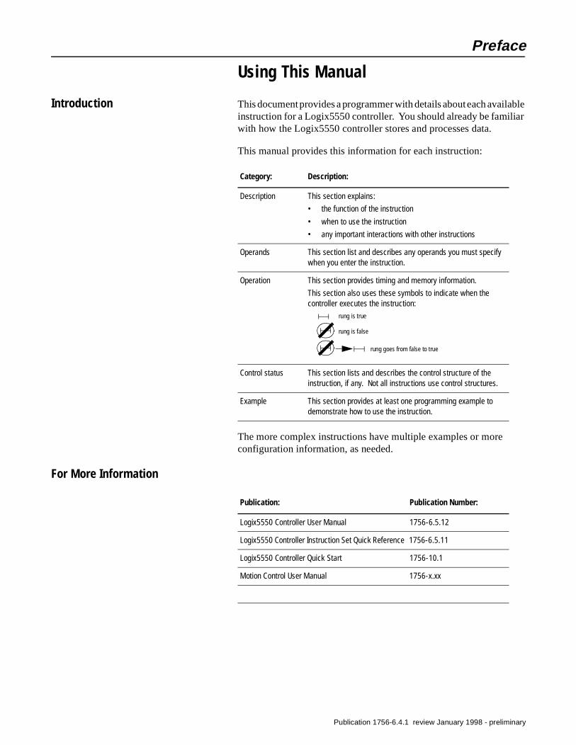
This manual provides this information for each instruction:
The more complex instructions have multiple examples or more configuration information, as needed.
For More Information
Category: Description:
Description This section explains:
• the function of the instruction
• when to use the instruction
• any important interactions with other instructions
Operands This section list and describes any operands you must specify when you enter the instruction.
Operation This section provides timing and memory information.
This section also uses these symbols to indicate when the controller executes the instruction:
Control status This section lists and describes the control structure of the instruction, if any. Not all instructions use control structures.
Example This section provides at least one programming example to demonstrate how to use the instruction.
rung is true
rung is false
rung goes from false to true
Publication: Publication Number:
Logix5550 Controller User Manual 1756-6.5.12
Logix5550 Controller Instruction Set Quick Reference 1756-6.5.11
Logix5550 Controller Quick Start 1756-10.1
Motion Control User Manual 1756-x.xx
Publication 1756-6.4.1 review January 1998 - preliminary

ii Using This Manual
Publication 1756-6.4.1 review January 1998 - preliminary
Table of Contents
Bit Instructions Chapter 1
Introduction . . . . . . . . . . . . . . . . . . . . . . . . . . . . . . . . . . . . . 1-1I/O Tags in Data Storage . . . . . . . . . . . . . . . . . . . . . . . . . . . . 1-1Rung Logic . . . . . . . . . . . . . . . . . . . . . . . . . . . . . . . . . . . . . . 1-1Examine On (XIC) . . . . . . . . . . . . . . . . . . . . . . . . . . . . . . . . . 1-2Examine Off (XIO) . . . . . . . . . . . . . . . . . . . . . . . . . . . . . . . . . 1-4Energize (OTE) . . . . . . . . . . . . . . . . . . . . . . . . . . . . . . . . . . . 1-6Latch (OTL) . . . . . . . . . . . . . . . . . . . . . . . . . . . . . . . . . . . . . . 1-8Unlatch (OTU) . . . . . . . . . . . . . . . . . . . . . . . . . . . . . . . . . . . 1-10One Shot (ONS) . . . . . . . . . . . . . . . . . . . . . . . . . . . . . . . . . . 1-12One Shot Rising (OSR). . . . . . . . . . . . . . . . . . . . . . . . . . . . . 1-14One Shot Falling (OSF) . . . . . . . . . . . . . . . . . . . . . . . . . . . . 1-16
Timer and Counter Instructions Chapter 2Introduction . . . . . . . . . . . . . . . . . . . . . . . . . . . . . . . . . . . . . 2-1Using Timers. . . . . . . . . . . . . . . . . . . . . . . . . . . . . . . . . . . . . 2-1
Timer Accuracy . . . . . . . . . . . . . . . . . . . . . . . . . . . . . . . . . 2-2Timer On Delay (TON) . . . . . . . . . . . . . . . . . . . . . . . . . . . . . . 2-3
Pausing a TON instruction . . . . . . . . . . . . . . . . . . . . . . . . . 2-4How controller mode can affect the TON instruction . . . . . 2-4
Timer Off Delay (TOF) . . . . . . . . . . . . . . . . . . . . . . . . . . . . . . 2-6How controller mode can affect the TOF instruction. . . . . . 2-7
Retentive Timer On (RTO) . . . . . . . . . . . . . . . . . . . . . . . . . . . 2-9How controller mode can affect the RTO instruction . . . . 2-10
Using Counters . . . . . . . . . . . . . . . . . . . . . . . . . . . . . . . . . . 2-12Count Up (CTU) . . . . . . . . . . . . . . . . . . . . . . . . . . . . . . . . . . 2-13Count Down (CTD). . . . . . . . . . . . . . . . . . . . . . . . . . . . . . . . 2-16Reset (RES) . . . . . . . . . . . . . . . . . . . . . . . . . . . . . . . . . . . . . 2-19
Publication 1756-6.4.1 review January 1998 - preliminary
toc–ii Table of Contents
Input/Output Instructions Chapter 3
Introduction. . . . . . . . . . . . . . . . . . . . . . . . . . . . . . . . . . . . . . 3-1Message (MSG) . . . . . . . . . . . . . . . . . . . . . . . . . . . . . . . . . . . 3-2Selecting the Message Type . . . . . . . . . . . . . . . . . . . . . . . . . 3-8
Specifying CIP messages. . . . . . . . . . . . . . . . . . . . . . . . . 3-10Specifying PLC-5 messages . . . . . . . . . . . . . . . . . . . . . . 3-10Specifying SLC messages . . . . . . . . . . . . . . . . . . . . . . . . 3-11Specifying block-transfer messages . . . . . . . . . . . . . . . . 3-11Specifying PLC-3 messages . . . . . . . . . . . . . . . . . . . . . . 3-12Specifying PLC-2 messages . . . . . . . . . . . . . . . . . . . . . . 3-12
Specifying the Communication Details. . . . . . . . . . . . . . . . . 3-13Mapping addresses . . . . . . . . . . . . . . . . . . . . . . . . . . . . . 3-13
MSG Programming Examples . . . . . . . . . . . . . . . . . . . . . . . 3-13CIP communications . . . . . . . . . . . . . . . . . . . . . . . . . . . . 3-13Ethernet communications . . . . . . . . . . . . . . . . . . . . . . . . 3-13ControlNet communications. . . . . . . . . . . . . . . . . . . . . . . 3-13Replacing PLC-5 block-transfer instructions . . . . . . . . . . 3-14
Get Status Value (GSV) and Set Status Value (SSV) . . . . . . . 3-15Accessing the AXIS object . . . . . . . . . . . . . . . . . . . . . . . . 3-16Accessing the CONTROLLER object . . . . . . . . . . . . . . . . . 3-16Accessing the CONTROLLERDEVICE object . . . . . . . . . . . 3-17Accessing the CST object . . . . . . . . . . . . . . . . . . . . . . . . 3-18Accessing the DF1 object . . . . . . . . . . . . . . . . . . . . . . . . 3-18Accessing the FAULTLOG object. . . . . . . . . . . . . . . . . . . . 3-20Accessing the MESSAGE object . . . . . . . . . . . . . . . . . . . . 3-21Accessing the MODULE object . . . . . . . . . . . . . . . . . . . . . 3-22Accessing the MOTIONGROUP object . . . . . . . . . . . . . . . . 3-22Accessing the PROGRAM object. . . . . . . . . . . . . . . . . . . . 3-22Accessing the ROUTINE object. . . . . . . . . . . . . . . . . . . . . 3-23Accessing the SERIALPORT object . . . . . . . . . . . . . . . . . . 3-24Accessing the TASK object . . . . . . . . . . . . . . . . . . . . . . . 3-25Accessing the WALLCLOCKTIME object . . . . . . . . . . . . . . 3-25
GSV/SSV Programming Example . . . . . . . . . . . . . . . . . . . . . 3-26Getting fault information . . . . . . . . . . . . . . . . . . . . . . . . . 3-26Setting enable and disable flags . . . . . . . . . . . . . . . . . . . 3-27
Publication 1756-6.4.1 review January 1998 - preliminary
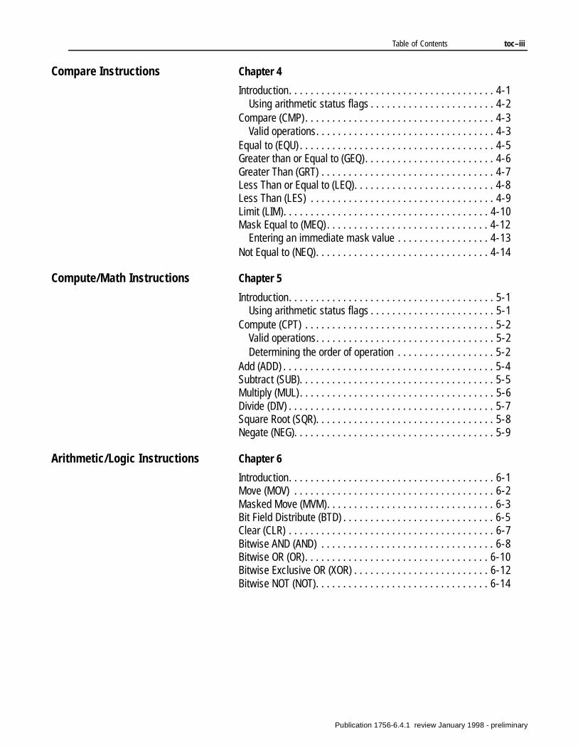
Table of Contents toc–iii
Compare Instructions Chapter 4
Introduction. . . . . . . . . . . . . . . . . . . . . . . . . . . . . . . . . . . . . . 4-1Using arithmetic status flags . . . . . . . . . . . . . . . . . . . . . . . 4-2
Compare (CMP) . . . . . . . . . . . . . . . . . . . . . . . . . . . . . . . . . . . 4-3Valid operations. . . . . . . . . . . . . . . . . . . . . . . . . . . . . . . . . 4-3
Equal to (EQU) . . . . . . . . . . . . . . . . . . . . . . . . . . . . . . . . . . . . 4-5Greater than or Equal to (GEQ). . . . . . . . . . . . . . . . . . . . . . . . 4-6Greater Than (GRT) . . . . . . . . . . . . . . . . . . . . . . . . . . . . . . . . 4-7Less Than or Equal to (LEQ). . . . . . . . . . . . . . . . . . . . . . . . . . 4-8Less Than (LES) . . . . . . . . . . . . . . . . . . . . . . . . . . . . . . . . . . 4-9Limit (LIM). . . . . . . . . . . . . . . . . . . . . . . . . . . . . . . . . . . . . . 4-10Mask Equal to (MEQ) . . . . . . . . . . . . . . . . . . . . . . . . . . . . . . 4-12
Entering an immediate mask value . . . . . . . . . . . . . . . . . 4-13Not Equal to (NEQ). . . . . . . . . . . . . . . . . . . . . . . . . . . . . . . . 4-14
Compute/Math Instructions Chapter 5
Introduction. . . . . . . . . . . . . . . . . . . . . . . . . . . . . . . . . . . . . . 5-1Using arithmetic status flags . . . . . . . . . . . . . . . . . . . . . . . 5-1
Compute (CPT) . . . . . . . . . . . . . . . . . . . . . . . . . . . . . . . . . . . 5-2Valid operations. . . . . . . . . . . . . . . . . . . . . . . . . . . . . . . . . 5-2Determining the order of operation . . . . . . . . . . . . . . . . . . 5-2
Add (ADD) . . . . . . . . . . . . . . . . . . . . . . . . . . . . . . . . . . . . . . . 5-4Subtract (SUB). . . . . . . . . . . . . . . . . . . . . . . . . . . . . . . . . . . . 5-5Multiply (MUL) . . . . . . . . . . . . . . . . . . . . . . . . . . . . . . . . . . . . 5-6Divide (DIV) . . . . . . . . . . . . . . . . . . . . . . . . . . . . . . . . . . . . . . 5-7Square Root (SQR). . . . . . . . . . . . . . . . . . . . . . . . . . . . . . . . . 5-8Negate (NEG). . . . . . . . . . . . . . . . . . . . . . . . . . . . . . . . . . . . . 5-9
Arithmetic/Logic Instructions Chapter 6
Introduction. . . . . . . . . . . . . . . . . . . . . . . . . . . . . . . . . . . . . . 6-1Move (MOV) . . . . . . . . . . . . . . . . . . . . . . . . . . . . . . . . . . . . . 6-2Masked Move (MVM). . . . . . . . . . . . . . . . . . . . . . . . . . . . . . . 6-3Bit Field Distribute (BTD) . . . . . . . . . . . . . . . . . . . . . . . . . . . . 6-5Clear (CLR) . . . . . . . . . . . . . . . . . . . . . . . . . . . . . . . . . . . . . . 6-7Bitwise AND (AND) . . . . . . . . . . . . . . . . . . . . . . . . . . . . . . . . 6-8Bitwise OR (OR). . . . . . . . . . . . . . . . . . . . . . . . . . . . . . . . . . 6-10Bitwise Exclusive OR (XOR) . . . . . . . . . . . . . . . . . . . . . . . . . 6-12Bitwise NOT (NOT). . . . . . . . . . . . . . . . . . . . . . . . . . . . . . . . 6-14
Publication 1756-6.4.1 review January 1998 - preliminary
toc–iv Table of Contents
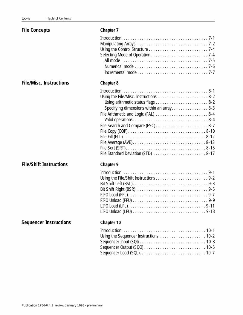
File Concepts Chapter 7
Introduction. . . . . . . . . . . . . . . . . . . . . . . . . . . . . . . . . . . . . . 7-1Manipulating Arrays . . . . . . . . . . . . . . . . . . . . . . . . . . . . . . . 7-2Using the Control Structure . . . . . . . . . . . . . . . . . . . . . . . . . . 7-4Selecting Mode of Operation . . . . . . . . . . . . . . . . . . . . . . . . . 7-4
All mode . . . . . . . . . . . . . . . . . . . . . . . . . . . . . . . . . . . . . . 7-5Numerical mode . . . . . . . . . . . . . . . . . . . . . . . . . . . . . . . . 7-6Incremental mode . . . . . . . . . . . . . . . . . . . . . . . . . . . . . . . 7-7
File/Misc. Instructions Chapter 8
Introduction. . . . . . . . . . . . . . . . . . . . . . . . . . . . . . . . . . . . . . 8-1Using the File/Misc. Instructions . . . . . . . . . . . . . . . . . . . . . . 8-2
Using arithmetic status flags . . . . . . . . . . . . . . . . . . . . . . . 8-2Specifying dimensions within an array. . . . . . . . . . . . . . . . 8-3
File Arithmetic and Logic (FAL) . . . . . . . . . . . . . . . . . . . . . . . 8-4Valid operations. . . . . . . . . . . . . . . . . . . . . . . . . . . . . . . . . 8-4
File Search and Compare (FSC) . . . . . . . . . . . . . . . . . . . . . . . 8-7File Copy (COP) . . . . . . . . . . . . . . . . . . . . . . . . . . . . . . . . . . 8-10File Fill (FLL) . . . . . . . . . . . . . . . . . . . . . . . . . . . . . . . . . . . . 8-12File Average (AVE) . . . . . . . . . . . . . . . . . . . . . . . . . . . . . . . . 8-13File Sort (SRT) . . . . . . . . . . . . . . . . . . . . . . . . . . . . . . . . . . . 8-15File Standard Deviation (STD) . . . . . . . . . . . . . . . . . . . . . . . 8-17
File/Shift Instructions Chapter 9
Introduction. . . . . . . . . . . . . . . . . . . . . . . . . . . . . . . . . . . . . . 9-1Using the File/Shift Instructions . . . . . . . . . . . . . . . . . . . . . . . 9-2Bit Shift Left (BSL) . . . . . . . . . . . . . . . . . . . . . . . . . . . . . . . . . 9-3Bit Shift Right (BSR) . . . . . . . . . . . . . . . . . . . . . . . . . . . . . . . 9-5FIFO Load (FFL) . . . . . . . . . . . . . . . . . . . . . . . . . . . . . . . . . . . 9-7FIFO Unload (FFU) . . . . . . . . . . . . . . . . . . . . . . . . . . . . . . . . . 9-9LIFO Load (LFL) . . . . . . . . . . . . . . . . . . . . . . . . . . . . . . . . . . 9-11LIFO Unload (LFU) . . . . . . . . . . . . . . . . . . . . . . . . . . . . . . . . 9-13
Sequencer Instructions Chapter 10
Introduction. . . . . . . . . . . . . . . . . . . . . . . . . . . . . . . . . . . . . 10-1Using the Sequencer Instructions . . . . . . . . . . . . . . . . . . . . 10-2Sequencer Input (SQI) . . . . . . . . . . . . . . . . . . . . . . . . . . . . . 10-3Sequencer Output (SQO) . . . . . . . . . . . . . . . . . . . . . . . . . . . 10-5Sequencer Load (SQL). . . . . . . . . . . . . . . . . . . . . . . . . . . . . 10-7
Publication 1756-6.4.1 review January 1998 - preliminary
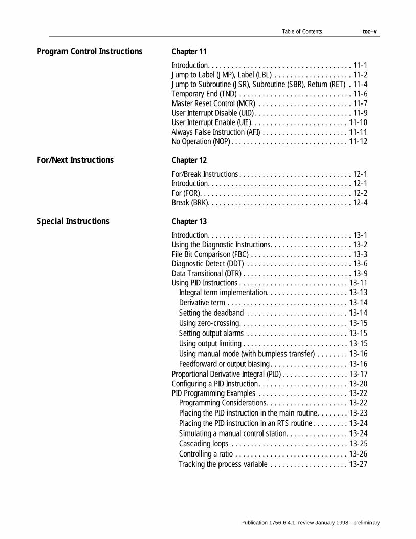
Table of Contents toc–v
Program Control Instructions Chapter 11
Introduction. . . . . . . . . . . . . . . . . . . . . . . . . . . . . . . . . . . . . 11-1Jump to Label (JMP), Label (LBL) . . . . . . . . . . . . . . . . . . . . 11-2Jump to Subroutine (JSR), Subroutine (SBR), Return (RET) . 11-4Temporary End (TND) . . . . . . . . . . . . . . . . . . . . . . . . . . . . . 11-6Master Reset Control (MCR) . . . . . . . . . . . . . . . . . . . . . . . . 11-7User Interrupt Disable (UID) . . . . . . . . . . . . . . . . . . . . . . . . . 11-9User Interrupt Enable (UIE). . . . . . . . . . . . . . . . . . . . . . . . . 11-10Always False Instruction (AFI) . . . . . . . . . . . . . . . . . . . . . . 11-11No Operation (NOP) . . . . . . . . . . . . . . . . . . . . . . . . . . . . . . 11-12
For/Next Instructions Chapter 12
For/Break Instructions . . . . . . . . . . . . . . . . . . . . . . . . . . . . . 12-1Introduction. . . . . . . . . . . . . . . . . . . . . . . . . . . . . . . . . . . . . 12-1For (FOR). . . . . . . . . . . . . . . . . . . . . . . . . . . . . . . . . . . . . . . 12-2Break (BRK). . . . . . . . . . . . . . . . . . . . . . . . . . . . . . . . . . . . . 12-4
Special Instructions Chapter 13
Introduction. . . . . . . . . . . . . . . . . . . . . . . . . . . . . . . . . . . . . 13-1Using the Diagnostic Instructions. . . . . . . . . . . . . . . . . . . . . 13-2File Bit Comparison (FBC) . . . . . . . . . . . . . . . . . . . . . . . . . . 13-3Diagnostic Detect (DDT) . . . . . . . . . . . . . . . . . . . . . . . . . . . 13-6Data Transitional (DTR) . . . . . . . . . . . . . . . . . . . . . . . . . . . . 13-9Using PID Instructions . . . . . . . . . . . . . . . . . . . . . . . . . . . . 13-11
Integral term implementation. . . . . . . . . . . . . . . . . . . . . 13-13Derivative term . . . . . . . . . . . . . . . . . . . . . . . . . . . . . . . 13-14Setting the deadband . . . . . . . . . . . . . . . . . . . . . . . . . . 13-14Using zero-crossing. . . . . . . . . . . . . . . . . . . . . . . . . . . . 13-15Setting output alarms . . . . . . . . . . . . . . . . . . . . . . . . . . 13-15Using output limiting . . . . . . . . . . . . . . . . . . . . . . . . . . . 13-15Using manual mode (with bumpless transfer) . . . . . . . . 13-16Feedforward or output biasing . . . . . . . . . . . . . . . . . . . . 13-16
Proportional Derivative Integral (PID) . . . . . . . . . . . . . . . . . 13-17Configuring a PID Instruction . . . . . . . . . . . . . . . . . . . . . . . 13-20PID Programming Examples . . . . . . . . . . . . . . . . . . . . . . . 13-22
Programming Considerations. . . . . . . . . . . . . . . . . . . . . 13-22Placing the PID instruction in the main routine. . . . . . . . 13-23Placing the PID instruction in an RTS routine . . . . . . . . . 13-24Simulating a manual control station. . . . . . . . . . . . . . . . 13-24Cascading loops . . . . . . . . . . . . . . . . . . . . . . . . . . . . . . 13-25Controlling a ratio . . . . . . . . . . . . . . . . . . . . . . . . . . . . . 13-26Tracking the process variable . . . . . . . . . . . . . . . . . . . . 13-27
Publication 1756-6.4.1 review January 1998 - preliminary
toc–vi Table of Contents
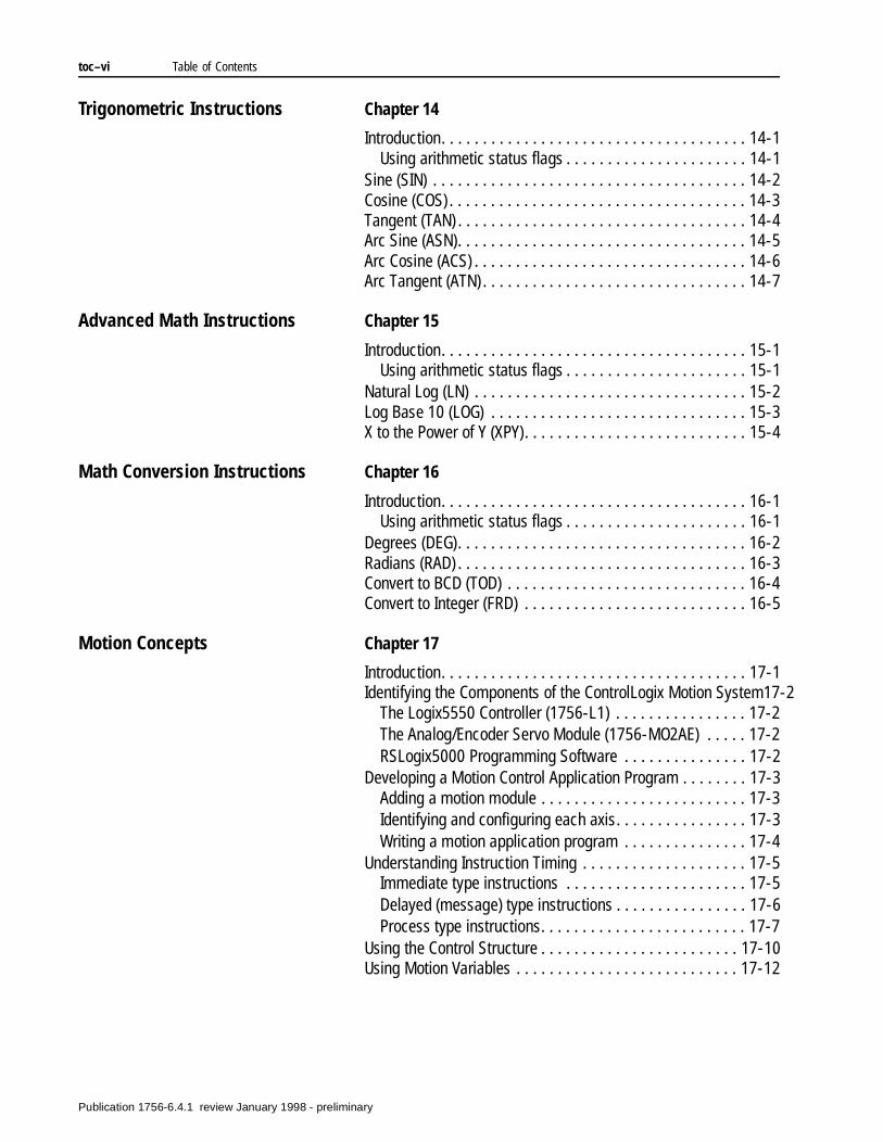
Trigonometric Instructions Chapter 14
Introduction. . . . . . . . . . . . . . . . . . . . . . . . . . . . . . . . . . . . . 14-1Using arithmetic status flags . . . . . . . . . . . . . . . . . . . . . . 14-1
Sine (SIN) . . . . . . . . . . . . . . . . . . . . . . . . . . . . . . . . . . . . . . 14-2Cosine (COS) . . . . . . . . . . . . . . . . . . . . . . . . . . . . . . . . . . . . 14-3Tangent (TAN) . . . . . . . . . . . . . . . . . . . . . . . . . . . . . . . . . . . 14-4Arc Sine (ASN). . . . . . . . . . . . . . . . . . . . . . . . . . . . . . . . . . . 14-5Arc Cosine (ACS) . . . . . . . . . . . . . . . . . . . . . . . . . . . . . . . . . 14-6Arc Tangent (ATN) . . . . . . . . . . . . . . . . . . . . . . . . . . . . . . . . 14-7
Advanced Math Instructions Chapter 15
Introduction. . . . . . . . . . . . . . . . . . . . . . . . . . . . . . . . . . . . . 15-1Using arithmetic status flags . . . . . . . . . . . . . . . . . . . . . . 15-1
Natural Log (LN) . . . . . . . . . . . . . . . . . . . . . . . . . . . . . . . . . 15-2Log Base 10 (LOG) . . . . . . . . . . . . . . . . . . . . . . . . . . . . . . . 15-3X to the Power of Y (XPY). . . . . . . . . . . . . . . . . . . . . . . . . . . 15-4
Math Conversion Instructions Chapter 16
Introduction. . . . . . . . . . . . . . . . . . . . . . . . . . . . . . . . . . . . . 16-1Using arithmetic status flags . . . . . . . . . . . . . . . . . . . . . . 16-1
Degrees (DEG). . . . . . . . . . . . . . . . . . . . . . . . . . . . . . . . . . . 16-2Radians (RAD) . . . . . . . . . . . . . . . . . . . . . . . . . . . . . . . . . . . 16-3Convert to BCD (TOD) . . . . . . . . . . . . . . . . . . . . . . . . . . . . . 16-4Convert to Integer (FRD) . . . . . . . . . . . . . . . . . . . . . . . . . . . 16-5
Motion Concepts Chapter 17
Introduction. . . . . . . . . . . . . . . . . . . . . . . . . . . . . . . . . . . . . 17-1Identifying the Components of the ControlLogix Motion System17-2
The Logix5550 Controller (1756-L1) . . . . . . . . . . . . . . . . 17-2The Analog/Encoder Servo Module (1756-MO2AE) . . . . . 17-2RSLogix5000 Programming Software . . . . . . . . . . . . . . . 17-2
Developing a Motion Control Application Program . . . . . . . . 17-3Adding a motion module . . . . . . . . . . . . . . . . . . . . . . . . . 17-3Identifying and configuring each axis. . . . . . . . . . . . . . . . 17-3Writing a motion application program . . . . . . . . . . . . . . . 17-4
Understanding Instruction Timing . . . . . . . . . . . . . . . . . . . . 17-5Immediate type instructions . . . . . . . . . . . . . . . . . . . . . . 17-5Delayed (message) type instructions . . . . . . . . . . . . . . . . 17-6Process type instructions. . . . . . . . . . . . . . . . . . . . . . . . . 17-7
Using the Control Structure . . . . . . . . . . . . . . . . . . . . . . . . 17-10Using Motion Variables . . . . . . . . . . . . . . . . . . . . . . . . . . . 17-12
Publication 1756-6.4.1 review January 1998 - preliminary
Table of Contents toc–vii
Motion Conversion Instructions Chapter 18
Introduction. . . . . . . . . . . . . . . . . . . . . . . . . . . . . . . . . . . . . 18-1Motion Servo On (MSO) . . . . . . . . . . . . . . . . . . . . . . . . . . . . 18-3Motion Servo Off (MSF) . . . . . . . . . . . . . . . . . . . . . . . . . . . . 18-5Motion Axis Shutdown (MASD) . . . . . . . . . . . . . . . . . . . . . . 18-7Motion Axis Shutdown Reset (MASR). . . . . . . . . . . . . . . . . 18-10Motion Direct Drive On (MDO) . . . . . . . . . . . . . . . . . . . . . . 18-12Motion Direct Drive Off (MDF) . . . . . . . . . . . . . . . . . . . . . . 18-14Motion Axis Fault Reset (MAFR) . . . . . . . . . . . . . . . . . . . . . 18-16
Motion Move Instructions Chapter 19
Introduction. . . . . . . . . . . . . . . . . . . . . . . . . . . . . . . . . . . . . 19-1Motion Axis Stop (MAS) . . . . . . . . . . . . . . . . . . . . . . . . . . . . 19-2Motion Axis Home (MAH) . . . . . . . . . . . . . . . . . . . . . . . . . . . 19-5Motion Axis Jog (MAJ). . . . . . . . . . . . . . . . . . . . . . . . . . . . . 19-8Motion Axis Move (MAM). . . . . . . . . . . . . . . . . . . . . . . . . . 19-11Motion Axis Gearing (MAG) . . . . . . . . . . . . . . . . . . . . . . . . 19-15Motion Change Dynamics (MCD) . . . . . . . . . . . . . . . . . . . . 19-18Motion Redefine Position (MRP). . . . . . . . . . . . . . . . . . . . . 19-21
Motion Group Instructions Chapter 20
Introduction. . . . . . . . . . . . . . . . . . . . . . . . . . . . . . . . . . . . . 20-1Motion Group Stop (MGS) . . . . . . . . . . . . . . . . . . . . . . . . . . 20-2Motion Group Program Stop (MGPS) . . . . . . . . . . . . . . . . . . 20-4Motion Group Shutdown (MGSD) . . . . . . . . . . . . . . . . . . . . . 20-6Motion Group Shutdown Reset (MGSR) . . . . . . . . . . . . . . . . 20-8Motion Group Strobe Position (MGSP) . . . . . . . . . . . . . . . . 20-10
Motion Event Instructions Chapter 21Introduction. . . . . . . . . . . . . . . . . . . . . . . . . . . . . . . . . . . . . 21-1Motion Arm Watch (MAW) . . . . . . . . . . . . . . . . . . . . . . . . . . 21-2Motion Disarm Watch (MDW). . . . . . . . . . . . . . . . . . . . . . . . 21-4Motion Arm Registration (MAR) . . . . . . . . . . . . . . . . . . . . . . 21-6Motion Disarm Registration (MDR). . . . . . . . . . . . . . . . . . . . 21-9
Motion Configuration Instructions
Chapter 22
Introduction. . . . . . . . . . . . . . . . . . . . . . . . . . . . . . . . . . . . . 22-1Motion Apply Axis Tuning (MAAT) . . . . . . . . . . . . . . . . . . . . 22-2Motion Run Axis Tuning (MRAT). . . . . . . . . . . . . . . . . . . . . . 22-4Motion Apply Hookup Diagnostics (MAHD) . . . . . . . . . . . . . . 22-7Motion Run Hookup Diagnostics (MRHD) . . . . . . . . . . . . . . . 22-9
Publication 1756-6.4.1 review January 1998 - preliminary

toc–viii Table of Contents
Notes:
Publication 1756-6.4.1 review January 1998 - preliminary
Chapter 1
Bit Instructions(XIC, XIO, OTE, OTL, OTU, ONS, OSR, OSF)
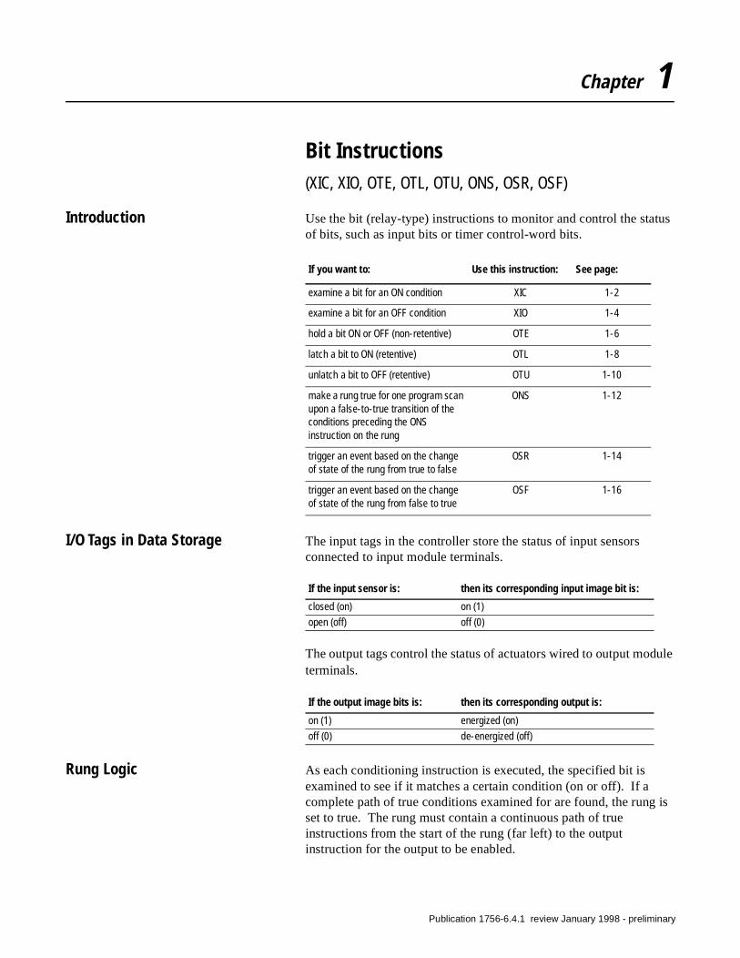
Introduction Use the bit (relay-type) instructions to monitor and control the status of bits, such as input bits or timer control-word bits.
I/O Tags in Data Storage The input tags in the controller store the status of input sensors connected to input module terminals.
The output tags control the status of actuators wired to output module terminals.
Rung Logic As each conditioning instruction is executed, the specified bit is examined to see if it matches a certain condition (on or off). If a complete path of true conditions examined for are found, the rung is set to true. The rung must contain a continuous path of true instructions from the start of the rung (far left) to the output instruction for the output to be enabled.
If you want to: Use this instruction: See page:
examine a bit for an ON condition XIC 1-2
examine a bit for an OFF condition XIO 1-4
hold a bit ON or OFF (non-retentive) OTE 1-6
latch a bit to ON (retentive) OTL 1-8
unlatch a bit to OFF (retentive) OTU 1-10
make a rung true for one program scan upon a false-to-true transition of the conditions preceding the ONS instruction on the rung
ONS 1-12
trigger an event based on the change of state of the rung from true to false
OSR 1-14
trigger an event based on the change of state of the rung from false to true
OSF 1-16
If the input sensor is: then its corresponding input image bit is:
closed (on) on (1)
open (off) off (0)
If the output image bits is: then its corresponding output is:
on (1) energized (on)
off (0) de-energized (off)
Publication 1756-6.4.1 review January 1998 - preliminary
1-2 Bit Instructions
Examine On (XIC)
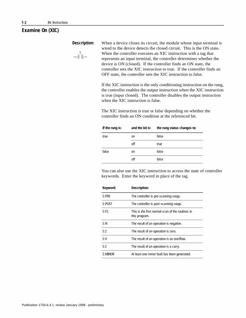
Description: When a device closes its circuit, the module whose input terminal is wired to the device detects the closed circuit. This is the ON state. When the controller executes an XIC instruction with a tag that represents an input terminal, the controller determines whether the device is ON (closed). If the controller finds an ON state, the controller sets the XIC instruction to true. If the controller finds an OFF state, the controller sets the XIC instruction to false.
If the XIC instruction is the only conditioning instruction on the rung, the controller enables the output instruction when the XIC instruction is true (input closed). The controller disables the output instruction when the XIC instruction is false.
The XIC instruction is true or false depending on whether the controller finds an ON condition at the referenced bit.
You can also use the XIC instruction to access the state of controller keywords. Enter the keyword in place of the tag.
If the rung is: and the bit is: the rung status changes to:
true on false
off true
false on false
off false
Keyword: Description:
S:PRE The controller is pre-scanning rungs.
S:POST The controller is post-scanning rungs.
S:FS This is the first normal scan of the routines in this program.
S:N The result of an operation is negative.
S:Z The result of an operation is zero.
S:V The result of an operation is an overflow.
S:C The result of an operation is a carry.
S:MINOR At least one minor fault has been generated.
Publication 1756-6.4.1 review January 1998 - preliminary
Bit Instructions 1-3
Operands:
Operation:
XIC Example:
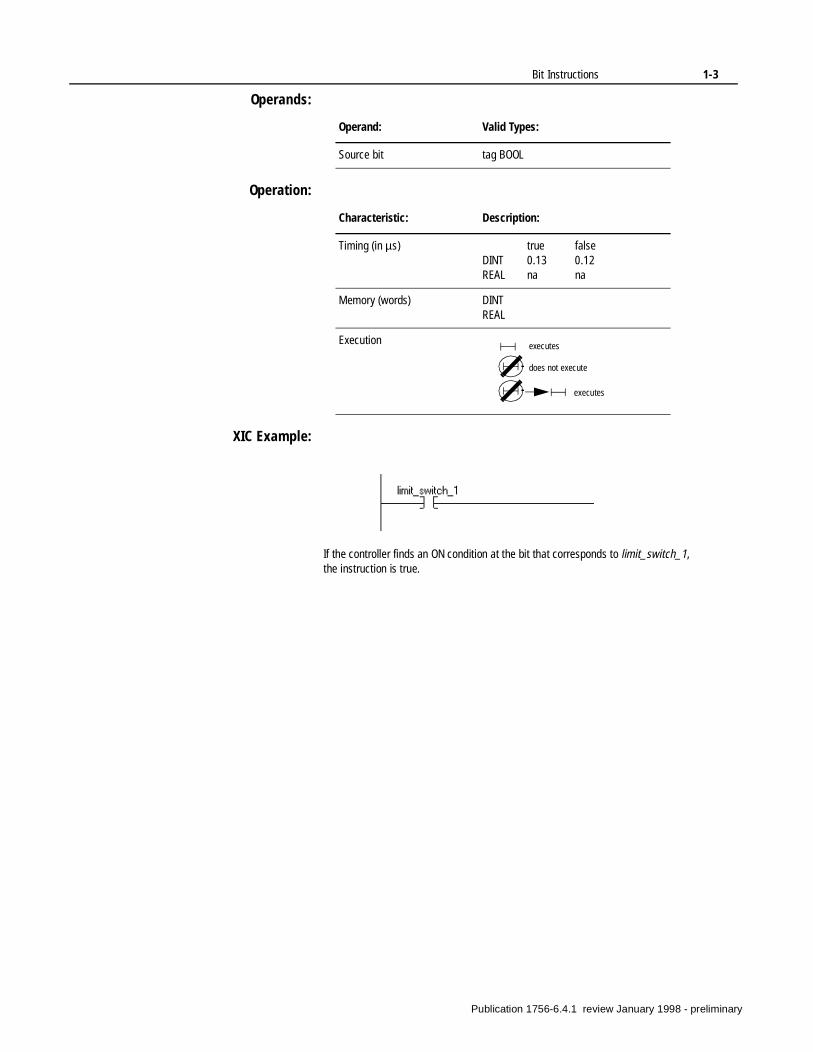
Operand: Valid Types:
Source bit tag BOOL
Characteristic: Description:
Timing (in µs) true falseDINT 0.13 0.12REAL na na
Memory (words) DINTREAL
Execution executes
does not execute
executes
If the controller finds an ON condition at the bit that corresponds to limit_switch_1, the instruction is true.
Publication 1756-6.4.1 review January 1998 - preliminary
1-4 Bit Instructions
Examine Off (XIO)
Description: When a device opens its circuit, the module whose input terminal is wired to the device detects an open circuit. This is the OFF state. When the controller finds an XIO instruction with a tag that represents an input terminal, the controller determines whether the device is OFF (open). If the controller finds an OFF state, the controller sets the XIO instruction to true. If the controller finds an ON state, the controller sets the XIO instruction to false.
If the XIO instruction is the only conditioning instruction on the rung, the controller enables the output instruction when the XIO instruction is true (input open). The controller disables the output instructions when the XIO instruction is false.
The XIO instruction is true or false depending on whether the controller finds an OFF or ON condition at the referenced bit.
You can also use the XIO instruction to access the state of controller keywords. Enter the keyword in place of the tag.
If the rung is: and the bit is: the rung status changes to:
true on true
off false
false on false
off false
Keyword: Description:
S:PRE The controller is pre-scanning rungs.
S:POST The controller is post-scanning rungs.
S:FS This is the first normal scan of the routines in this program.
S:N The result of an operation is negative.
S:Z The result of an operation is zero.
S:V The result of an operation is an overflow.
S:C The result of an operation is a carry.
S:MINOR At least one minor fault has been generated.
Publication 1756-6.4.1 review January 1998 - preliminary
Bit Instructions 1-5
Operands:
Operation:
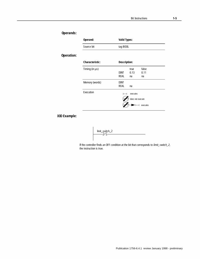
XIO Example:
Operand: Valid Types:
Source bit tag BOOL
Characteristic: Description:
Timing (in µs) true falseDINT 0.13 0.11REAL na na
Memory (words) DINTREAL na
Execution executes
does not execute
executes
If the controller finds an OFF condition at the bit that corresponds to limit_switch_2, the instruction is true.
Publication 1756-6.4.1 review January 1998 - preliminary
1-6 Bit Instructions
Energize (OTE)
Description: Use the OTE instruction to control a bit. If the bit corresponds to an output module terminal, the device wired to this terminal is energized when the instruction is enabled. The device is de-energized when the instruction is disabled. If the output conditions that precede the OTE instruction are true, the controller enables the OTE instruction. If the output conditions that preceded the OTE instruction are false, the controller disables the OTE instructions. When rung conditions become false, the corresponding device de-energizes.
An OTE instruction is similar to a relay coil. The OTE instruction is controlled by preceding input instructions; the relay coil is controlled by contacts in its hard-wired rung.
The OTE instruction tells the controller how to control the referenced bit based on the rung condition.
Operands:
Operation:
If the rung is: the controller turns the bit:
true on (1)
false off (0)
Operand: Valid Types:
Destination bit tag BOOL
Characteristic: Description:
Timing (in µs) true falseDINT 0.19 0.19REAL na na
Memory (words) DINTREAL na
Execution executes
does not execute
executes
Publication 1756-6.4.1 review January 1998 - preliminary
Bit Instructions 1-7
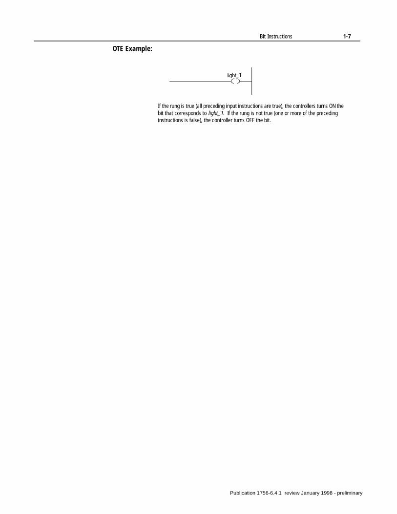
OTE Example:
If the rung is true (all preceding input instructions are true), the controllers turns ON the bit that corresponds to light_1. If the rung is not true (one or more of the preceding instructions is false), the controller turns OFF the bit.
Publication 1756-6.4.1 review January 1998 - preliminary
1-8 Bit Instructions
Latch (OTL)
Description: The OTL instruction is a retentive output instruction that can only turn on a bit (in cannot turn off a bit). This instruction is usually used with an OTU (unlatch) instruction, with both instructions referencing the same bit.
When you assign a tag to an OTL instruction that corresponds to a terminal of an output module, the input device wired to this terminal is energized when the controller sets (enables) the bit. If the input conditions that precede the OTL instruction are true, the controller enables the OTL instruction. When rung conditions become false (after being true), the bit remains set and the corresponding output device remains energized. Use the OTU instruction to turn off the bit you latched on with the OTL instruction.
When enabled, the OTL instruction tells the controller to turn on the referenced bit. Thereafter, the bit remains on, regardless of the rung condition, until the bit is turned off, typically by an unlatch (OTU) instruction in another rung.
Operands:
Operation:
If the rung is: the controller turns the bit:
true on (1)
false no change
Operand: Valid Types:
Destination bit tag BOOL
Characteristic: Description:
Timing (in µs) true falseDINT 0.20 0.13REAL na na
Memory (words) DINTREAL na
Execution executes
does not execute
executes
Publication 1756-6.4.1 review January 1998 - preliminary

Bit Instructions 1-9
OTL Example:
If the rung is true (all preceding input instructions are true), the controllers turns ON the bit that corresponds to light_2. This bit remains ON until it is reset by an OTU instruction.
Publication 1756-6.4.1 review January 1998 - preliminary
1-10 Bit Instructions
Unlatch (OTU)
Description: The OTU instruction is a retentive output instruction that can only turn off a bit (it cannot turn on a bit). This instruction is usually used with an OTL (latch) instruction, with both instructions referencing the same bit. The OTU instruction turns off the bit, which was turned on (latched) by the OTL instruction.
When the controller changes from Run to Program mode or when the controller loses power (and there is battery backup), the bit remains in the state set by the last rung of the latch/unlatch pair that was true.
The OTU instruction tells the controller to turn off the referenced bit based on the rung condition. Thereafter, the bit remains off, regardless of the rung condition, until it is turned on, typically by an OTL instruction in another rung.
Operands:
Operation:
If the rung is: the controller turns the bit:
true off (0)
false no change
Operand: Valid Types:
Destination bit tag BOOL
Characteristic: Description:
Timing (in µs) true falseDINT 0.20 0.11REAL na na
Memory (words) DINTREAL na
Execution executes
does not execute
executes
Publication 1756-6.4.1 review January 1998 - preliminary

Bit Instructions 1-11
OTU Example:
If the rung is true (all preceding input instructions are true), the controllers turns OFF the bit that corresponds to light_2.
Publication 1756-6.4.1 review January 1998 - preliminary
1-12 Bit Instructions
One Shot (ONS)
Description: The ONS instruction is an input instruction that makes the rung true for one program scan upon a false-to-true transition of the conditions preceding the ONS instruction on the rung.
Use the ONS instruction to start events that are triggered by a pushbutton, such as pulling values from thumbwheel switches or freezing rapidly displayed LED values. You must enter a tag for the bit. Dedicate a unique bit to each ONS instruction.
During prescan, the bit tag is set to prevent false triggering when the program scan begins.
Operands:
Operation:
!ATTENTION: You can program an output tag for the ONS instruction, but be aware that on-line programming with this instruction can be dangerous because the output might turn on immediately when the rung is scanned. Set the bit tag to 1 before entering the instruction. Then the rung must go from false to true before energizing the output.
Operand: Valid Types:
Source bit tag BOOL
Characteristic: Description:
Timing (in µs) true falseDINTREAL na na
Memory (words) DINTREAL na
Execution does not execute
does not execute
executes
Publication 1756-6.4.1 review January 1998 - preliminary

Bit Instructions 1-13
ONS Example:
The ONS instruction makes the rung true for one scan upon a false-to-true transition of any preceding instructions.
Publication 1756-6.4.1 review January 1998 - preliminary
1-14 Bit Instructions
One Shot Rising (OSR)
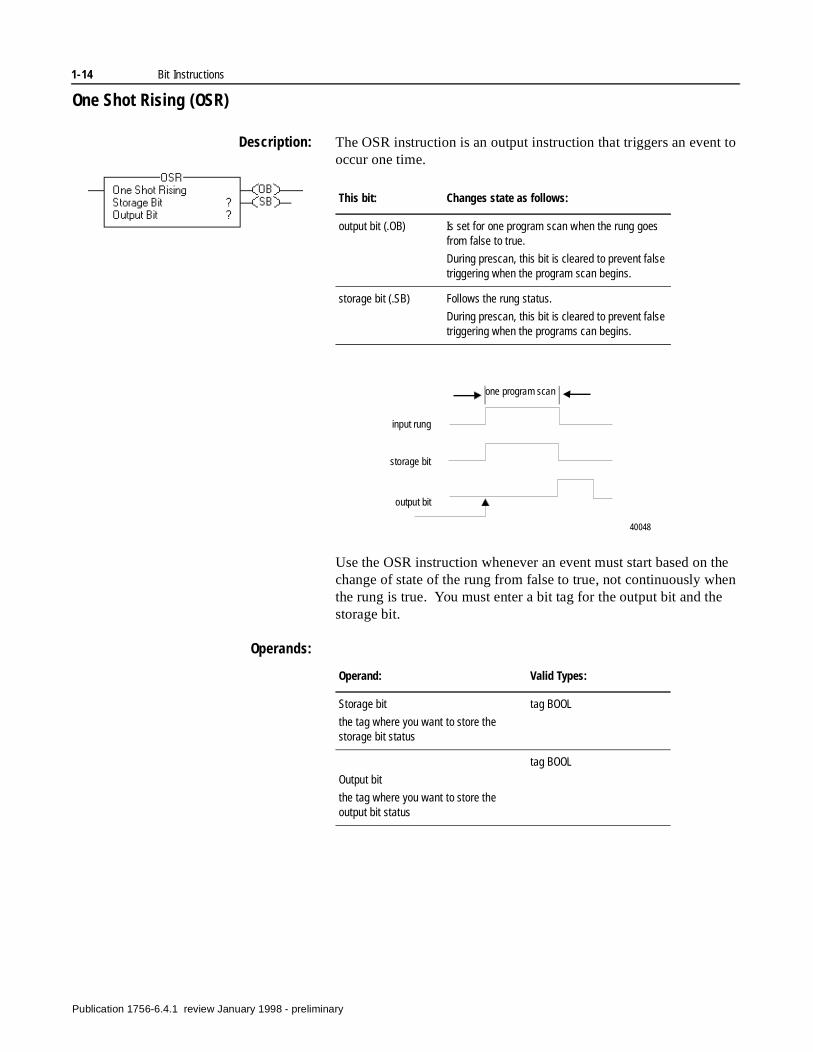
Description: The OSR instruction is an output instruction that triggers an event to occur one time.
Use the OSR instruction whenever an event must start based on the change of state of the rung from false to true, not continuously when the rung is true. You must enter a bit tag for the output bit and the storage bit.
Operands:
This bit: Changes state as follows:
output bit (.OB) Is set for one program scan when the rung goes from false to true.
During prescan, this bit is cleared to prevent false triggering when the program scan begins.
storage bit (.SB) Follows the rung status.
During prescan, this bit is cleared to prevent false triggering when the programs can begins.
one program scan
input rung
storage bit
output bit
40048
Operand: Valid Types:
Storage bit
the tag where you want to store the storage bit status
tag BOOL
Output bit
the tag where you want to store the output bit status
tag BOOL
Publication 1756-6.4.1 review January 1998 - preliminary
Bit Instructions 1-15
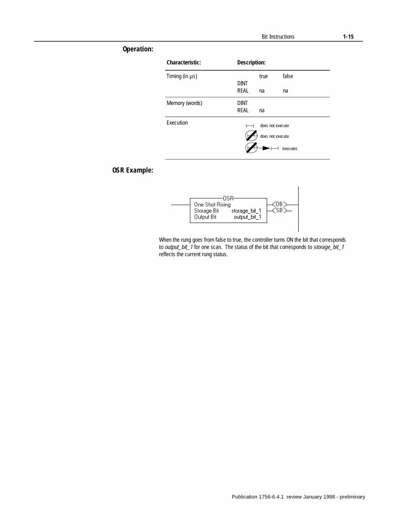
Operation:
OSR Example:
Characteristic: Description:
Timing (in µs) true falseDINTREAL na na
Memory (words) DINTREAL na
Execution does not execute
does not execute
executes
When the rung goes from false to true, the controller turns ON the bit that corresponds to output_bit_1 for one scan. The status of the bit that corresponds to storage_bit_1 reflects the current rung status.
Publication 1756-6.4.1 review January 1998 - preliminary
1-16 Bit Instructions
One Shot Falling (OSF)
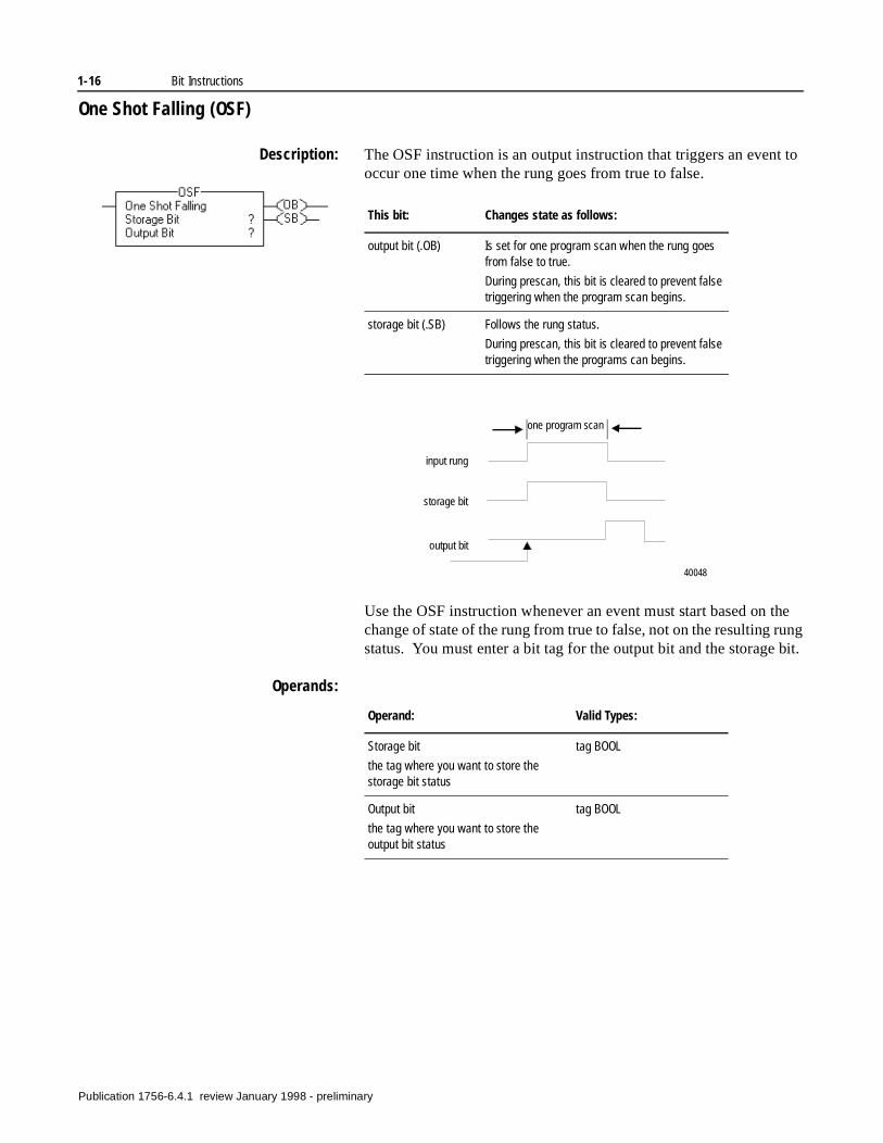
Description: The OSF instruction is an output instruction that triggers an event to occur one time when the rung goes from true to false.
Use the OSF instruction whenever an event must start based on the change of state of the rung from true to false, not on the resulting rung status. You must enter a bit tag for the output bit and the storage bit.
Operands:
This bit: Changes state as follows:
output bit (.OB) Is set for one program scan when the rung goes from false to true.
During prescan, this bit is cleared to prevent false triggering when the program scan begins.
storage bit (.SB) Follows the rung status.
During prescan, this bit is cleared to prevent false triggering when the programs can begins.
one program scan
input rung
storage bit
output bit
40048
Operand: Valid Types:
Storage bit
the tag where you want to store the storage bit status
tag BOOL
Output bit
the tag where you want to store the output bit status
tag BOOL
Publication 1756-6.4.1 review January 1998 - preliminary
Bit Instructions 1-17
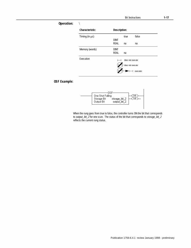
Operation: \
OSF Example:
Characteristic: Description:
Timing (in µs) true falseDINTREAL na na
Memory (words) DINTREAL na
Execution does not execute
does not execute
executes
When the rung goes from true to false, the controller turns ON the bit that corresponds to output_bit_2 for one scan. The status of the bit that corresponds to storage_bit_2 reflects the current rung status.
Publication 1756-6.4.1 review January 1998 - preliminary

1-18 Bit Instructions
Notes:
Publication 1756-6.4.1 review January 1998 - preliminary
Chapter 2
Timer and Counter Instructions(TON, TOF, RTO, CTU, CTD, RES)
Introduction Timers and counters control operations based on time or the number of events.
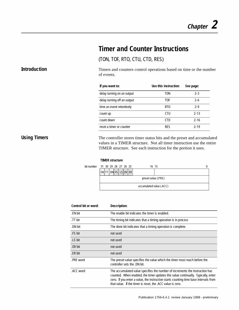
Using Timers The controller stores timer status bits and the preset and accumulated values in a TIMER structure. Not all timer instruction use the entire TIMER structure. See each instruction for the portion it uses.
If you want to: Use this instruction: See page:
delay turning on an output TON 2-3
delay turning off an output TOF 2-6
time an event retentively RTO 2-9
count up CTU 2-13
count down CTD 2-16
reset a timer or counter RES 2-19
31 30 29 28 27 26 25 16 15 0
TIMER structure
preset value (.PRE)
accumulated value (.ACC)
EN TT DN FS LS OV ER
bit number
Control bit or word: Description:
.EN bit The enable bit indicates the timer is enabled.
.TT bit The timing bit indicates that a timing operation is in process
.DN bit The done bit indicates that a timing operation is complete.
.FS bit not used
.LS bit not used
.OV bit not used
.ER bit not used
.PRE word The preset value specifies the value which the timer must reach before the controller sets the .DN bit.
.ACC word The accumulated value specifies the number of increments the instruction has counted. When enabled, the timer updates this value continually. Typically, enter zero. If you enter a value, the instruction starts counting time base intervals from that value. If the timer is reset, the .ACC value is zero.
Publication 1756-6.4.1 review January 1998 - preliminary

2-2 Timer and Counter Instructions
To access timer control bits, the preset value, or the accumulated value, use the tag mnemonic. For example, timer1.pre accesses the preset value for the tag timer1.
Timer Accuracy
The time base is 1 msec for all timers. Timer accuracy depends on the controller clock tolerance, which is + 0.02%. A timer could time out early or late by 1 msec.
The displayed accumulated value of a timer shows the actual time, but it is dependent on the CRT update time. The accumulated value might appear to be less than the preset when the .DN bit is set.
Publication 1756-6.4.1 review January 1998 - preliminary
Timer and Counter Instructions 2-3
E)
Timer On Delay (TON)
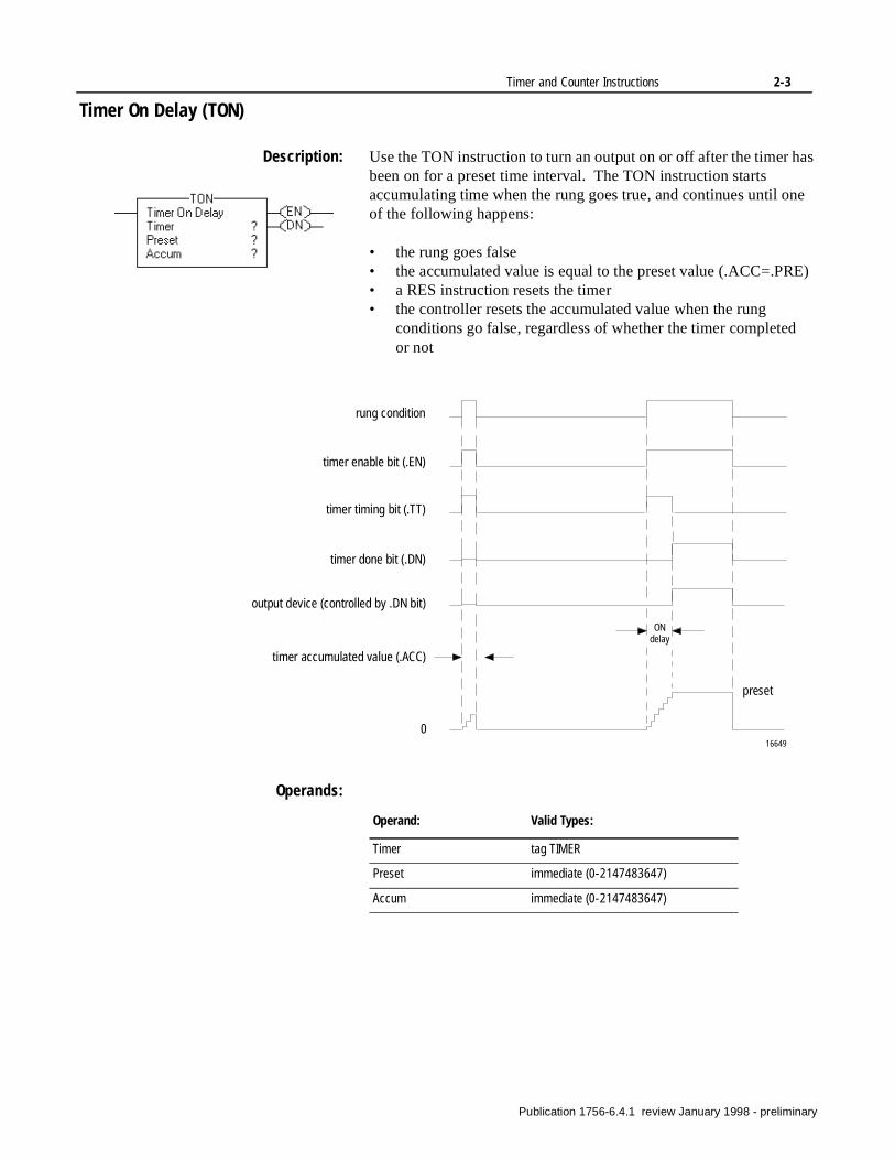
Description: Use the TON instruction to turn an output on or off after the timer has been on for a preset time interval. The TON instruction starts accumulating time when the rung goes true, and continues until one of the following happens:
• the rung goes false• the accumulated value is equal to the preset value (.ACC=.PR• a RES instruction resets the timer• the controller resets the accumulated value when the rung
conditions go false, regardless of whether the timer completedor not
Operands:
rung condition
timer enable bit (.EN)
timer done bit (.DN)
timer accumulated value (.ACC)
timer timing bit (.TT)
output device (controlled by .DN bit)
preset
0
ON delay
16649
Operand: Valid Types:
Timer tag TIMER
Preset immediate (0-2147483647)
Accum immediate (0-2147483647)
Publication 1756-6.4.1 review January 1998 - preliminary
2-4 Timer and Counter Instructions
Control status:
Pausing a TON instruction
If you set the .DN bit using an OTE instruction you can pause the timer. The .EN and .TT bits remain set, but the .ACC value does not increment. Timing resumes when you clear the .DN bit. If the rung goes false while the timer is paused, the timer resets as normal.
How controller mode can affect the TON instruction
If you change to Program mode, or the controller loses power, before the timer reaches the .PRE value, the following occurs:
• .EN bit remains set• .TT bit remains set• .ACC value remains the same
Control bit or word: Description:
.EN bit The enable bit is set when the rung goes true. It is reset when:
• the rung goes false
• a RES instruction resets the timer
.TT bit The timing bit is set when the rung goes true. It is reset when:
• the rung goes false
• the .DN bit is set (.ACC=.PRE)
• a RES instruction resets the timer
.DN bit The done bit is set when the accumulated value is equal to the preset value (.ACC=.PRE). It is reset when:
• the rung goes false
• a RES instruction resets the timer
.PRE word The preset value specifies the value which the timer must reach before the controller sets the .DN bit.
.ACC word The accumulated value specifies the number of increments the instruction has counted. When enabled, the timer updates this value continually. Typically, enter zero. If you enter a value, the instruction starts counting time base intervals from that value. If the timer is reset, the .ACC value is zero.
Publication 1756-6.4.1 review January 1998 - preliminary
Timer and Counter Instructions 2-5
Then when you switch back to Run or Test mode, or power is restored, the following occurs:
Operation:
TON Example:
Condition: Result:
If the rung is true .EN bit remains set
.TT bit remains set
.DN bit remains reset
.ACC value is reset and starts incrementing
If the rung is false .EN bit is reset
.TT bit is reset
.DN bit is reset
.ACC value is reset
Characteristic: Description:
Timing (in µs) true falseDINTREAL
Memory (words) DINTREAL
Execution does not execute
does not execute
executes
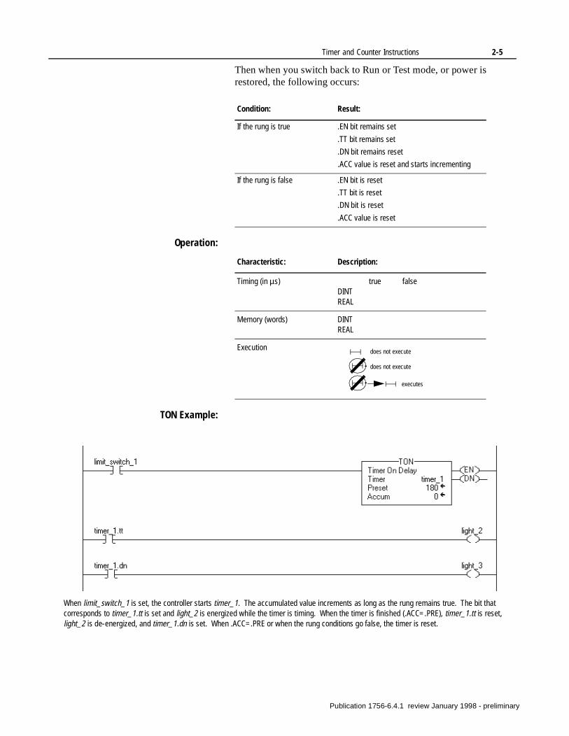
When limit_switch_1 is set, the controller starts timer_1. The accumulated value increments as long as the rung remains true. The bit that corresponds to timer_1.tt is set and light_2 is energized while the timer is timing. When the timer is finished (.ACC=.PRE), timer_1.tt is reset, light_2 is de-energized, and timer_1.dn is set. When .ACC=.PRE or when the rung conditions go false, the timer is reset.
Publication 1756-6.4.1 review January 1998 - preliminary
2-6 Timer and Counter Instructions
Timer Off Delay (TOF)
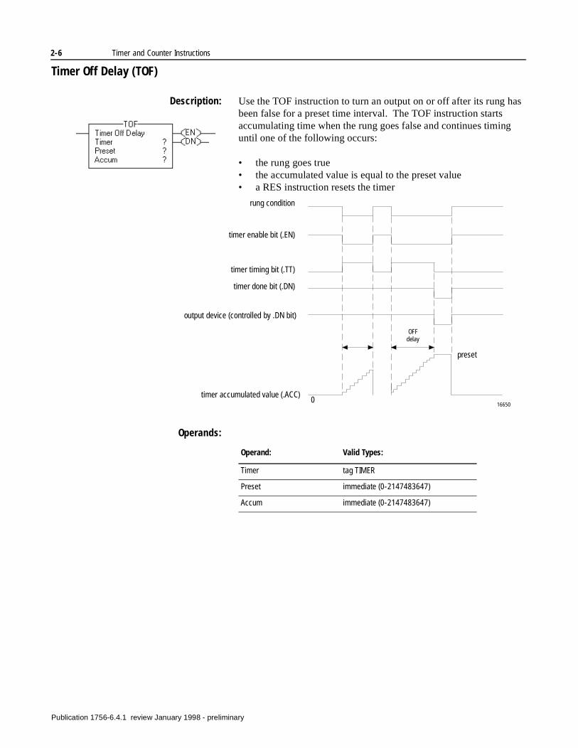
Description: Use the TOF instruction to turn an output on or off after its rung has been false for a preset time interval. The TOF instruction starts accumulating time when the rung goes false and continues timing until one of the following occurs:
• the rung goes true• the accumulated value is equal to the preset value• a RES instruction resets the timer
Operands:
rung condition
timer enable bit (.EN)
timer done bit (.DN)
timer accumulated value (.ACC)
timer timing bit (.TT)
output device (controlled by .DN bit)
preset
0
OFF delay
16650
Operand: Valid Types:
Timer tag TIMER
Preset immediate (0-2147483647)
Accum immediate (0-2147483647)
Publication 1756-6.4.1 review January 1998 - preliminary
Timer and Counter Instructions 2-7
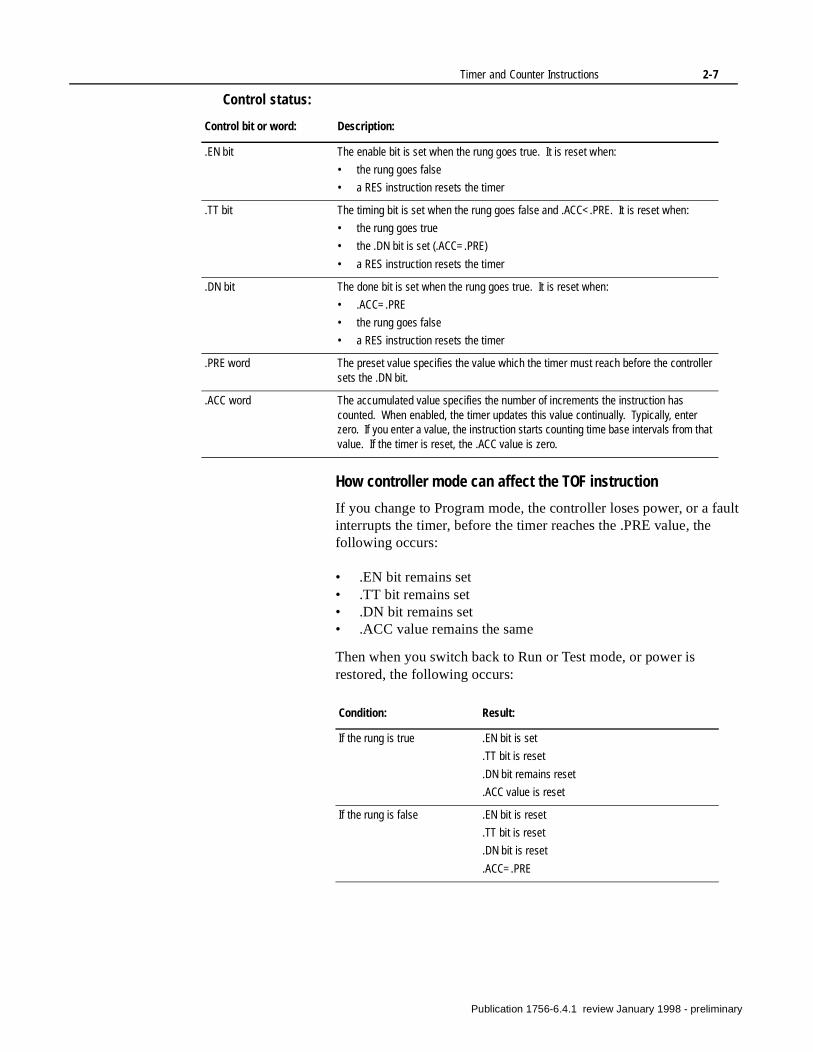
Control status:
How controller mode can affect the TOF instruction
If you change to Program mode, the controller loses power, or a fault interrupts the timer, before the timer reaches the .PRE value, the following occurs:
• .EN bit remains set• .TT bit remains set• .DN bit remains set• .ACC value remains the same
Then when you switch back to Run or Test mode, or power is restored, the following occurs:
Control bit or word: Description:
.EN bit The enable bit is set when the rung goes true. It is reset when:
• the rung goes false
• a RES instruction resets the timer
.TT bit The timing bit is set when the rung goes false and .ACC<.PRE. It is reset when:
• the rung goes true
• the .DN bit is set (.ACC=.PRE)
• a RES instruction resets the timer
.DN bit The done bit is set when the rung goes true. It is reset when:
• .ACC=.PRE
• the rung goes false
• a RES instruction resets the timer
.PRE word The preset value specifies the value which the timer must reach before the controller sets the .DN bit.
.ACC word The accumulated value specifies the number of increments the instruction has counted. When enabled, the timer updates this value continually. Typically, enter zero. If you enter a value, the instruction starts counting time base intervals from that value. If the timer is reset, the .ACC value is zero.
Condition: Result:
If the rung is true .EN bit is set
.TT bit is reset
.DN bit remains reset
.ACC value is reset
If the rung is false .EN bit is reset
.TT bit is reset
.DN bit is reset
.ACC=.PRE
Publication 1756-6.4.1 review January 1998 - preliminary
2-8 Timer and Counter Instructions
During prescan:
• .TT bit is reset• .ACC value is set equal to the .PRE value
Operation:
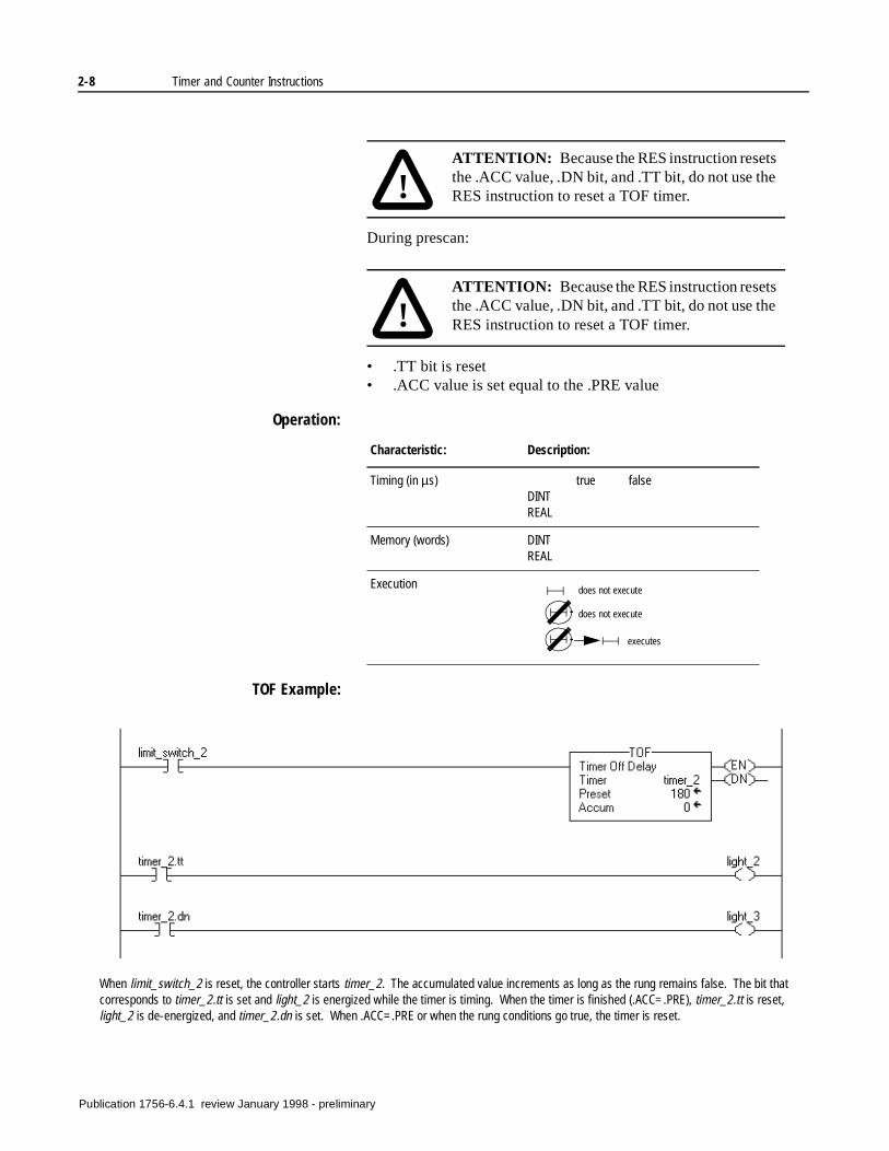
TOF Example:
!ATTENTION: Because the RES instruction resets the .ACC value, .DN bit, and .TT bit, do not use the RES instruction to reset a TOF timer.
!ATTENTION: Because the RES instruction resets the .ACC value, .DN bit, and .TT bit, do not use the RES instruction to reset a TOF timer.
Characteristic: Description:
Timing (in µs) true falseDINTREAL
Memory (words) DINTREAL
Execution does not execute
does not execute
executes
When limit_switch_2 is reset, the controller starts timer_2. The accumulated value increments as long as the rung remains false. The bit that corresponds to timer_2.tt is set and light_2 is energized while the timer is timing. When the timer is finished (.ACC=.PRE), timer_2.tt is reset, light_2 is de-energized, and timer_2.dn is set. When .ACC=.PRE or when the rung conditions go true, the timer is reset.
Publication 1756-6.4.1 review January 1998 - preliminary
Timer and Counter Instructions 2-9
ng
h
TO
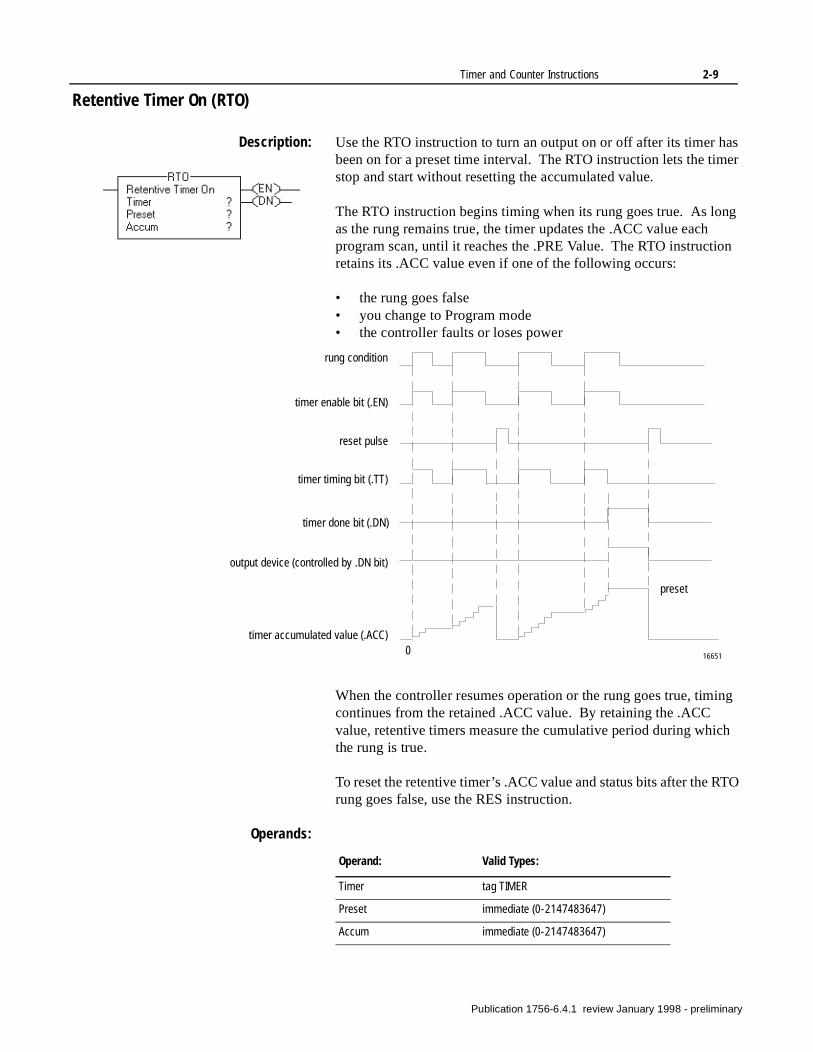
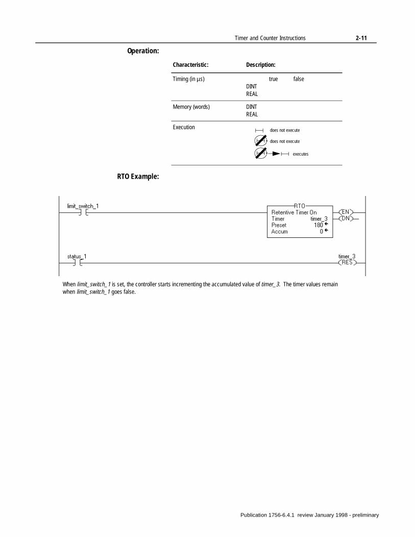
Retentive Timer On (RTO)
Description: Use the RTO instruction to turn an output on or off after its timer has been on for a preset time interval. The RTO instruction lets the timer stop and start without resetting the accumulated value.
The RTO instruction begins timing when its rung goes true. As long as the rung remains true, the timer updates the .ACC value each program scan, until it reaches the .PRE Value. The RTO instruction retains its .ACC value even if one of the following occurs:
• the rung goes false• you change to Program mode• the controller faults or loses power
When the controller resumes operation or the rung goes true, timicontinues from the retained .ACC value. By retaining the .ACC value, retentive timers measure the cumulative period during whicthe rung is true.
To reset the retentive timer’s .ACC value and status bits after the Rrung goes false, use the RES instruction.
Operands:
rung condition
timer enable bit (.EN)
timer done bit (.DN)
timer accumulated value (.ACC)
timer timing bit (.TT)
output device (controlled by .DN bit)
preset
0 16651
reset pulse
Operand: Valid Types:
Timer tag TIMER
Preset immediate (0-2147483647)
Accum immediate (0-2147483647)
Publication 1756-6.4.1 review January 1998 - preliminary
2-10 Timer and Counter Instructions
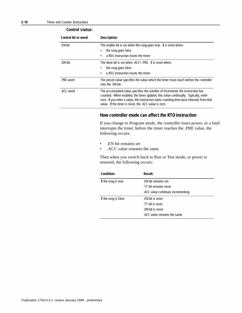
Control status:
How controller mode can affect the RTO instruction
If you change to Program mode, the controller loses power, or a fault interrupts the timer, before the timer reaches the .PRE value, the following occurs:
• .EN bit remains set• .ACC value remains the same
Then when you switch back to Run or Test mode, or power is restored, the following occurs:
Control bit or word: Description:
.EN bit The enable bit is set when the rung goes true. It is reset when:
• the rung goes false
• a RES instruction resets the timer
.DN bit The done bit is set when .ACC=.PRE. It is reset when:
• the rung goes false
• a RES instruction resets the timer
.PRE word The preset value specifies the value which the timer must reach before the controller sets the .DN bit.
.ACC word The accumulated value specifies the number of increments the instruction has counted. When enabled, the timer updates this value continually. Typically, enter zero. If you enter a value, the instruction starts counting time base intervals from that value. If the timer is reset, the .ACC value is zero.
Condition: Result:
If the rung is true .EN bit remains set
.TT bit remains reset
.ACC value continues incrementing
If the rung is false .EN bit is reset
.TT bit is reset
.DN bit is reset
.ACC value remains the same
Publication 1756-6.4.1 review January 1998 - preliminary
Timer and Counter Instructions 2-11
Operation:
RTO Example:
Characteristic: Description:
Timing (in µs) true falseDINTREAL
Memory (words) DINTREAL
Execution does not execute
does not execute
executes
When limit_switch_1 is set, the controller starts incrementing the accumulated value of timer_3. The timer values remain when limit_switch_1 goes false.
Publication 1756-6.4.1 review January 1998 - preliminary
2-12 Timer and Counter Instructions
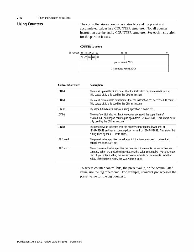
Using Counters The controller stores controller status bits and the preset and accumulated values in a COUNTER structure. Not all counter instruction use the entire COUNTER structure. See each instruction for the portion it uses.
To access counter control bits, the preset value, or the accumulated value, use the tag mnemonic. For example, counter1.pre accesses the preset value for the tag counter1.
preset value (.PRE)
accumulated value (.ACC)
CU CD DN OV UN
31 30 29 28 27 16 15 0bit number
COUNTER structure
Control bit or word: Description:
.CU bit The count up enable bit indicates that the instruction has increased its count. This status bit is only used by the CTU instruction.
.CD bit The count down enable bit indicates that the instruction has decreased its count. This status bit is only used by the CTD instruction.
.DN bit The done bit indicates that a counting operation is complete.
.OV bit The overflow bit indicates that the counter exceeded the upper limit of 2147483648 and began counting up again from -2147483648. This status bit is only used by the CTU instruction.
.UN bit The underflow bit indicates that the counter exceeded the lower limit of -2147483648 and began counting down again from 2147483648. This status bit is only used by the CTD instruction.
.PRE word The preset value specifies the value which the timer must reach before the controller sets the .DN bit.
.ACC word The accumulated value specifies the number of increments the instruction has counted. When enabled, the timer updates this value continually. Typically, enter zero. If you enter a value, the instruction increments or decrements from that value. If the timer is reset, the .ACC value is zero.
Publication 1756-6.4.1 review January 1998 - preliminary
Timer and Counter Instructions 2-13
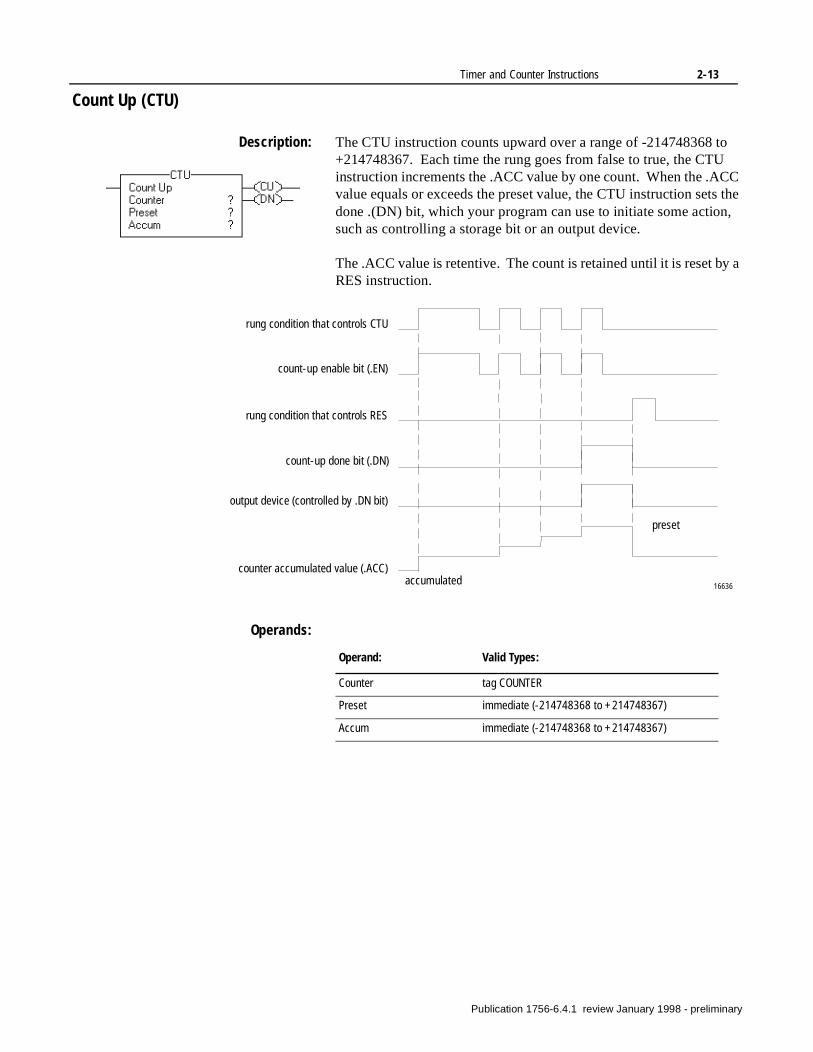
Count Up (CTU)
Description: The CTU instruction counts upward over a range of -214748368 to +214748367. Each time the rung goes from false to true, the CTU instruction increments the .ACC value by one count. When the .ACC value equals or exceeds the preset value, the CTU instruction sets the done .(DN) bit, which your program can use to initiate some action, such as controlling a storage bit or an output device.
The .ACC value is retentive. The count is retained until it is reset by a RES instruction.
Operands:
rung condition that controls CTU
count-up enable bit (.EN)
count-up done bit (.DN)
counter accumulated value (.ACC)
rung condition that controls RES
output device (controlled by .DN bit)
preset
accumulated 16636
Operand: Valid Types:
Counter tag COUNTER
Preset immediate (-214748368 to +214748367)
Accum immediate (-214748368 to +214748367)
Publication 1756-6.4.1 review January 1998 - preliminary
2-14 Timer and Counter Instructions
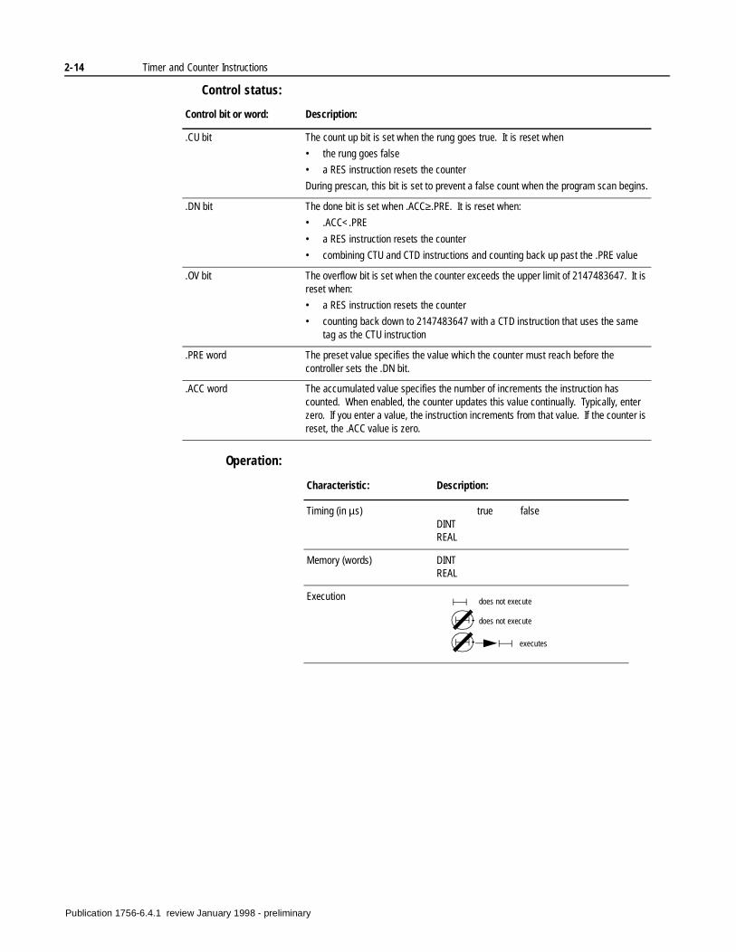
Control status:
Operation:
Control bit or word: Description:
.CU bit The count up bit is set when the rung goes true. It is reset when
• the rung goes false
• a RES instruction resets the counter
During prescan, this bit is set to prevent a false count when the program scan begins.
.DN bit The done bit is set when .ACC≥.PRE. It is reset when:
• .ACC<.PRE
• a RES instruction resets the counter
• combining CTU and CTD instructions and counting back up past the .PRE value
.OV bit The overflow bit is set when the counter exceeds the upper limit of 2147483647. It is reset when:
• a RES instruction resets the counter
• counting back down to 2147483647 with a CTD instruction that uses the same tag as the CTU instruction
.PRE word The preset value specifies the value which the counter must reach before the controller sets the .DN bit.
.ACC word The accumulated value specifies the number of increments the instruction has counted. When enabled, the counter updates this value continually. Typically, enter zero. If you enter a value, the instruction increments from that value. If the counter is reset, the .ACC value is zero.
Characteristic: Description:
Timing (in µs) true falseDINTREAL
Memory (words) DINTREAL
Execution does not execute
does not execute
executes
Publication 1756-6.4.1 review January 1998 - preliminary
Timer and Counter Instructions 2-15
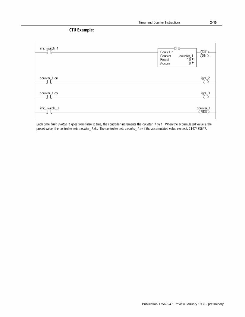
CTU Example:
Each time limit_switch_1 goes from false to true, the controller increments the counter_1 by 1. When the accumulated value ≥ the preset value, the controller sets counter_1.dn. The controller sets counter_1.ov if the accumulated value exceeds 2147483647.
Publication 1756-6.4.1 review January 1998 - preliminary
2-16 Timer and Counter Instructions
Count Down (CTD)
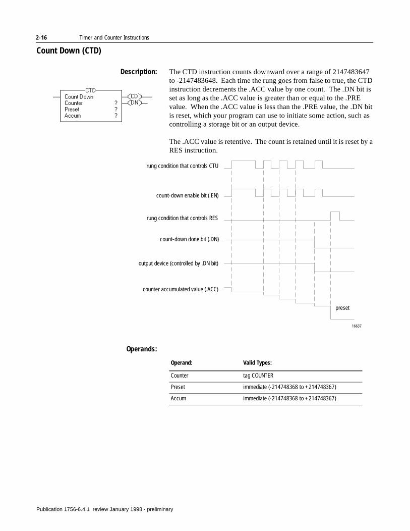
Description: The CTD instruction counts downward over a range of 2147483647 to -2147483648. Each time the rung goes from false to true, the CTD instruction decrements the .ACC value by one count. The .DN bit is set as long as the .ACC value is greater than or equal to the .PRE value. When the .ACC value is less than the .PRE value, the .DN bit is reset, which your program can use to initiate some action, such as controlling a storage bit or an output device.
The .ACC value is retentive. The count is retained until it is reset by a RES instruction.
Operands:
rung condition that controls CTU
count-down enable bit (.EN)
count-down done bit (.DN)
counter accumulated value (.ACC)
rung condition that controls RES
output device (controlled by .DN bit)
preset
16637
Operand: Valid Types:
Counter tag COUNTER
Preset immediate (-214748368 to +214748367)
Accum immediate (-214748368 to +214748367)
Publication 1756-6.4.1 review January 1998 - preliminary
Timer and Counter Instructions 2-17
Control status:
Operation:
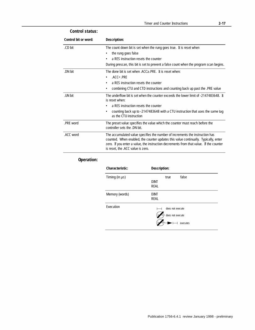
Control bit or word: Description:
.CD bit The count down bit is set when the rung goes true. It is reset when
• the rung goes false
• a RES instruction resets the counter
During prescan, this bit is set to prevent a false count when the program scan begins.
.DN bit The done bit is set when .ACC≥.PRE. It is reset when:
• .ACC<.PRE
• a RES instruction resets the counter
• combining CTU and CTD instructions and counting back up past the .PRE value
.UN bit The underflow bit is set when the counter exceeds the lower limit of -2147483648. It is reset when:
• a RES instruction resets the counter
• counting back up to -2147483648 with a CTU instruction that uses the same tag as the CTU instruction
.PRE word The preset value specifies the value which the counter must reach before the controller sets the .DN bit.
.ACC word The accumulated value specifies the number of increments the instruction has counted. When enabled, the counter updates this value continually. Typically, enter zero. If you enter a value, the instruction decrements from that value. If the counter is reset, the .ACC value is zero.
Characteristic: Description:
Timing (in µs) true falseDINTREAL
Memory (words) DINTREAL
Execution does not execute
does not execute
executes
Publication 1756-6.4.1 review January 1998 - preliminary
2-18 Timer and Counter Instructions
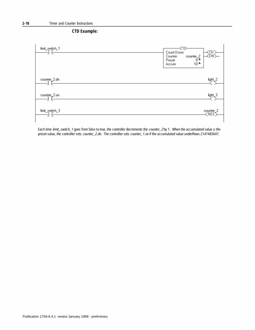
CTD Example:
Each time limit_switch_1 goes from false to true, the controller decrements the counter_2 by 1. When the accumulated value ≥ the preset value, the controller sets counter_2.dn. The controller sets counter_1.ov if the accumulated value underflows 2147483647.
Publication 1756-6.4.1 review January 1998 - preliminary
Timer and Counter Instructions 2-19
Reset (RES)
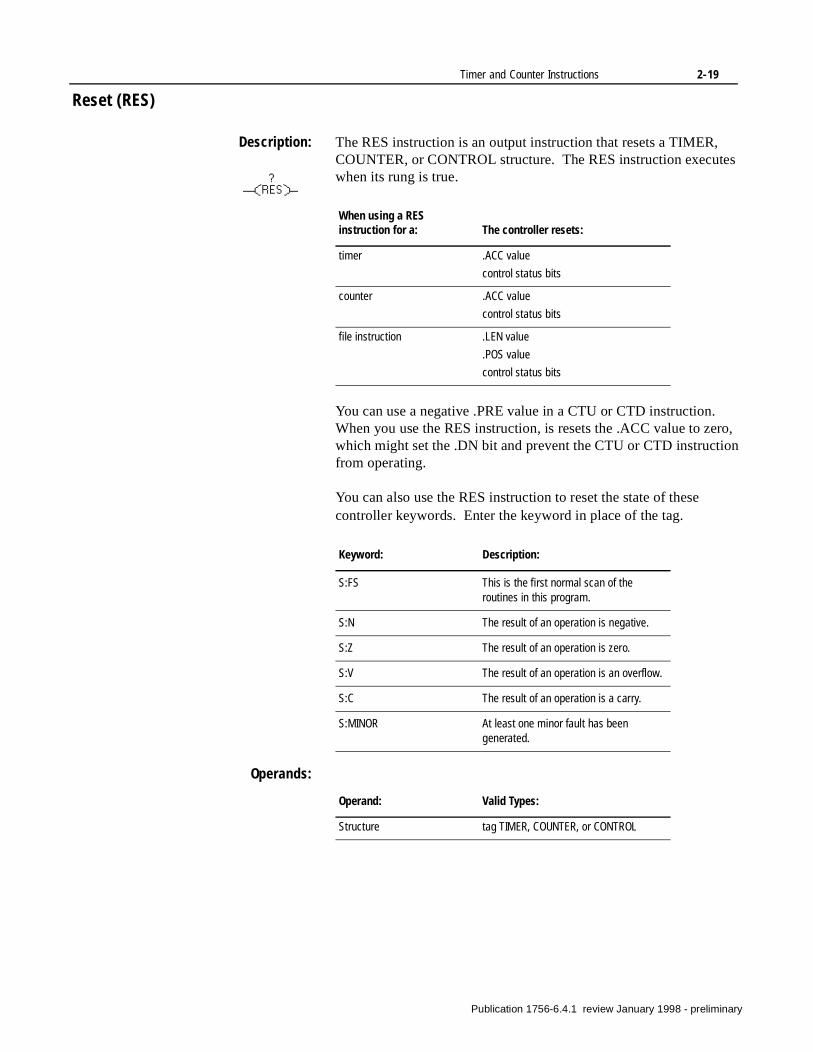
Description: The RES instruction is an output instruction that resets a TIMER, COUNTER, or CONTROL structure. The RES instruction executes when its rung is true.
You can use a negative .PRE value in a CTU or CTD instruction. When you use the RES instruction, is resets the .ACC value to zero, which might set the .DN bit and prevent the CTU or CTD instruction from operating.
You can also use the RES instruction to reset the state of these controller keywords. Enter the keyword in place of the tag.
Operands:
When using a RES instruction for a: The controller resets:
timer .ACC value
control status bits
counter .ACC value
control status bits
file instruction .LEN value
.POS value
control status bits
Keyword: Description:
S:FS This is the first normal scan of the routines in this program.
S:N The result of an operation is negative.
S:Z The result of an operation is zero.
S:V The result of an operation is an overflow.
S:C The result of an operation is a carry.
S:MINOR At least one minor fault has been generated.
Operand: Valid Types:
Structure tag TIMER, COUNTER, or CONTROL
Publication 1756-6.4.1 review January 1998 - preliminary
2-20 Timer and Counter Instructions
Operation:
RES Example:
Characteristic: Description:
Timing (in µs) true falseDINTREAL
Memory (words) DINTREAL
Execution executes
does not execute
executes
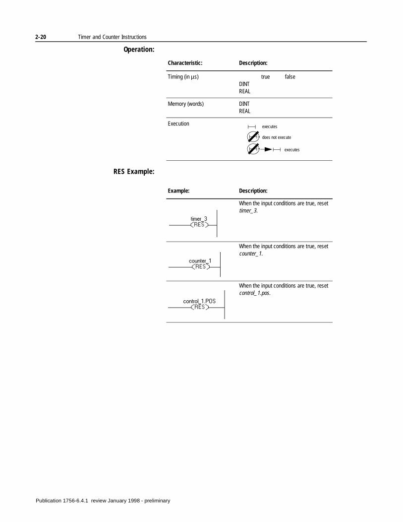
Example: Description:
When the input conditions are true, reset timer_3.
When the input conditions are true, reset counter_1.
When the input conditions are true, reset control_1.pos.
Publication 1756-6.4.1 review January 1998 - preliminary
Chapter 3
Input/Output Instructions(MSG, GSV, SSV)
Introduction The input/output instructions read or write data to or from the controller or a block of data to or from another station on the network.
If you want to: Use this instruction: See page:
send data to or from another device MSG 3-2
get controller status information GSV 3-15
set controller status information SSV 3-15
Publication 1756-6.4.1 review January 1998 - preliminary
3-2 Input/Output Instructions
Message (MSG)
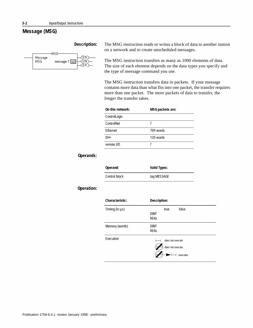
Description: The MSG instruction reads or writes a block of data to another station on a network and to create unscheduled messages.
The MSG instruction transfers as many as 1000 elements of data. The size of each element depends on the data types you specify and the type of message command you use.
The MSG instruction transfers data in packets. If your message contains more data than what fits into one packet, the transfer requires more than one packet. The more packets of data to transfer, the longer the transfer takes.
Operands:
Operation:
On this network: MSG packets are:
ControlLogix
ControlNet ?
Ethernet 709 words
DH+ 120 words
remote I/O ?
Operand: Valid Types:
Control block tag MESSAGE
Characteristic: Description:
Timing (in µs) true falseDINTREAL
Memory (words) DINTREAL
Execution does not execute
does not execute
executes
Publication 1756-6.4.1 review January 1998 - preliminary
Input/Output Instructions 3-3
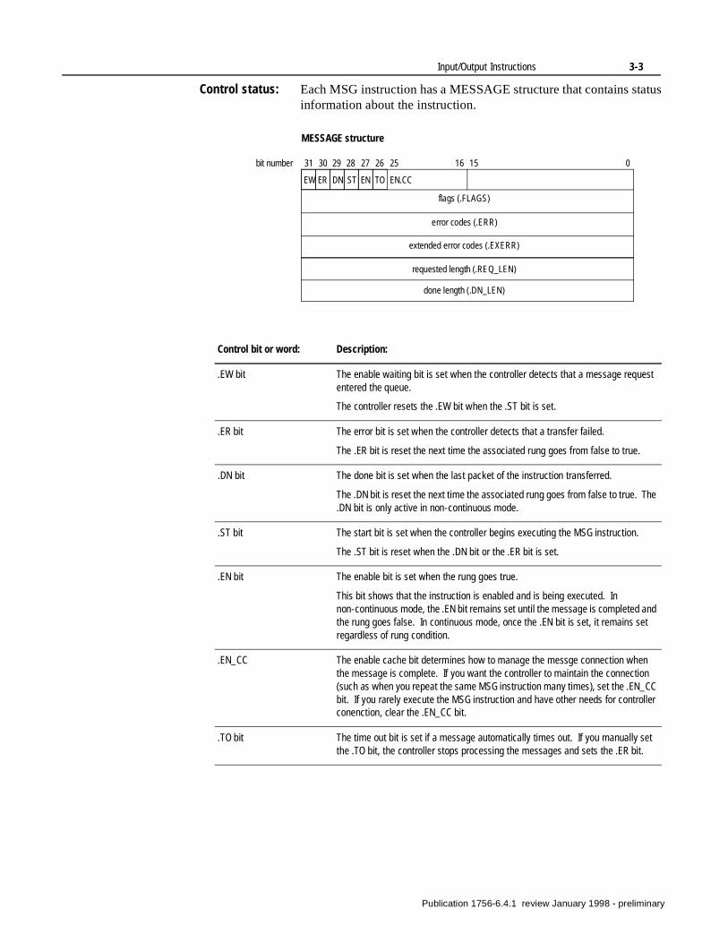
Control status: Each MSG instruction has a MESSAGE structure that contains status information about the instruction.
MESSAGE structure
flags (.FLAGS)
error codes (.ERR)
EW ER DN ST EN TO EN.CC
extended error codes (.EXERR)
requested length (.REQ_LEN)
done length (.DN_LEN)
31 30 29 28 27 26 25 16 15 0bit number
Control bit or word: Description:
.EW bit The enable waiting bit is set when the controller detects that a message request entered the queue.
The controller resets the .EW bit when the .ST bit is set.
.ER bit The error bit is set when the controller detects that a transfer failed.
The .ER bit is reset the next time the associated rung goes from false to true.
.DN bit The done bit is set when the last packet of the instruction transferred.
The .DN bit is reset the next time the associated rung goes from false to true. The .DN bit is only active in non-continuous mode.
.ST bit The start bit is set when the controller begins executing the MSG instruction.
The .ST bit is reset when the .DN bit or the .ER bit is set.
.EN bit The enable bit is set when the rung goes true.
This bit shows that the instruction is enabled and is being executed. In non-continuous mode, the .EN bit remains set until the message is completed and the rung goes false. In continuous mode, once the .EN bit is set, it remains set regardless of rung condition.
.EN_CC The enable cache bit determines how to manage the messge connection when the message is complete. If you want the controller to maintain the connection (such as when you repeat the same MSG instruction many times), set the .EN_CC bit. If you rarely execute the MSG instruction and have other needs for controller conenction, clear the .EN_CC bit.
.TO bit The time out bit is set if a message automatically times out. If you manually set the .TO bit, the controller stops processing the messages and sets the .ER bit.
Publication 1756-6.4.1 review January 1998 - preliminary
3-4 Input/Output Instructions
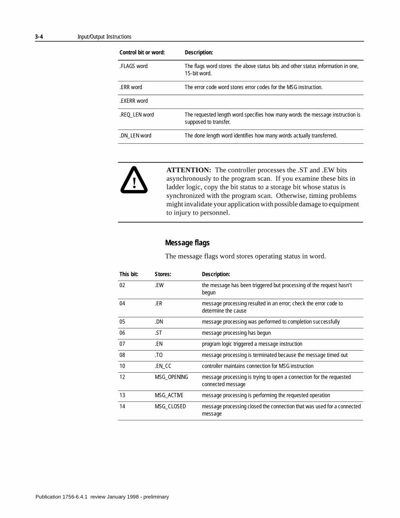
Message flags
The message flags word stores operating status in word.
.FLAGS word The flags word stores the above status bits and other status information in one, 15-bit word.
.ERR word The error code word stores error codes for the MSG instruction.
.EXERR word
.REQ_LEN word The requested length word specifies how many words the message instruction is supposed to transfer.
.DN_LEN word The done length word identifies how many words actually transferred.
!ATTENTION: The controller processes the .ST and .EW bits asynchronously to the program scan. If you examine these bits in ladder logic, copy the bit status to a storage bit whose status is synchronized with the program scan. Otherwise, timing problems might invalidate your application with possible damage to equipment to injury to personnel.
This bit: Stores: Description:
02 .EW the message has been triggered but processing of the request hasn’t begun
04 .ER message processing resulted in an error; check the error code to determine the cause
05 .DN message processing was performed to completion successfully
06 .ST message processing has begun
07 .EN program logic triggered a message instruction
08 .TO message processing is terminated because the message timed out
10 .EN_CC controller maintains connection for MSG instruction
12 MSG_OPENING message processing is trying to open a connection for the requested connected message
13 MSG_ACTIVE message processing is performing the requested operation
14 MSG_CLOSED message processing closed the connection that was used for a connected message
Control bit or word: Description:
Publication 1756-6.4.1 review January 1998 - preliminary
Input/Output Instructions 3-5
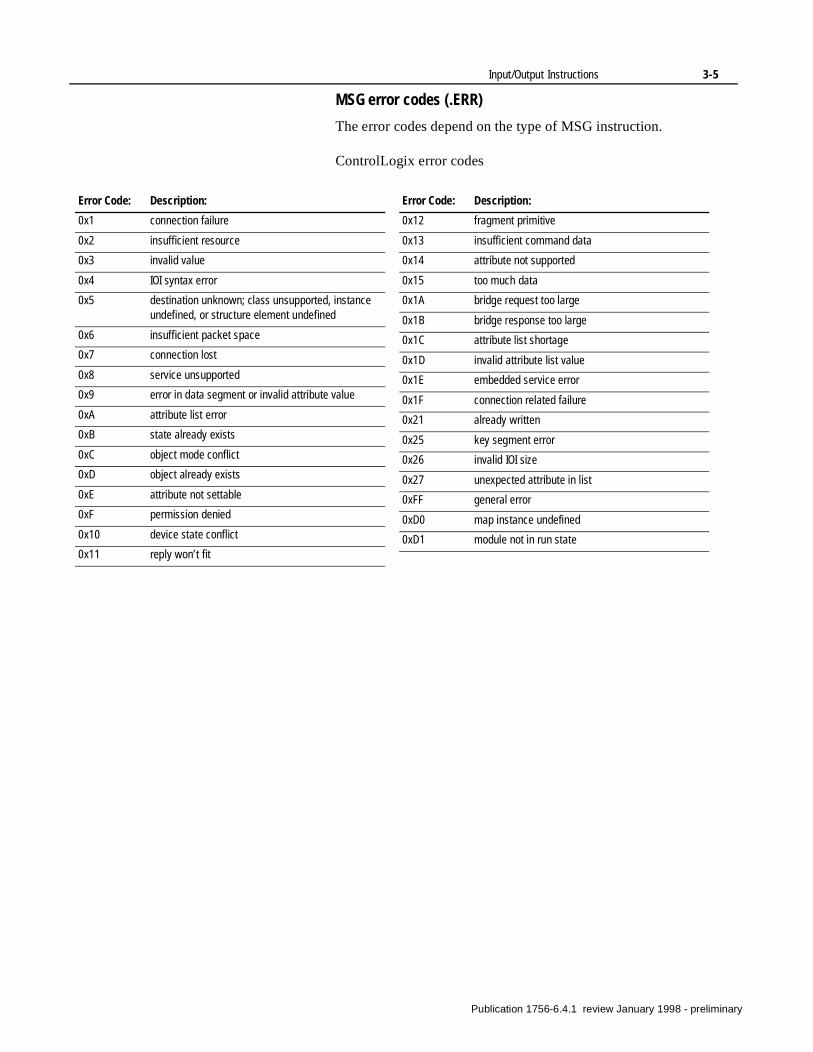
MSG error codes (.ERR)
The error codes depend on the type of MSG instruction.
ControlLogix error codes
Error Code: Description:
0x1 connection failure
0x2 insufficient resource
0x3 invalid value
0x4 IOI syntax error
0x5 destination unknown; class unsupported, instance undefined, or structure element undefined
0x6 insufficient packet space
0x7 connection lost
0x8 service unsupported
0x9 error in data segment or invalid attribute value
0xA attribute list error
0xB state already exists
0xC object mode conflict
0xD object already exists
0xE attribute not settable
0xF permission denied
0x10 device state conflict
0x11 reply won’t fit
0x12 fragment primitive
0x13 insufficient command data
0x14 attribute not supported
0x15 too much data
0x1A bridge request too large
0x1B bridge response too large
0x1C attribute list shortage
0x1D invalid attribute list value
0x1E embedded service error
0x1F connection related failure
0x21 already written
0x25 key segment error
0x26 invalid IOI size
0x27 unexpected attribute in list
0xFF general error
0xD0 map instance undefined
0xD1 module not in run state
Error Code: Description:
Publication 1756-6.4.1 review January 1998 - preliminary
3-6 Input/Output Instructions
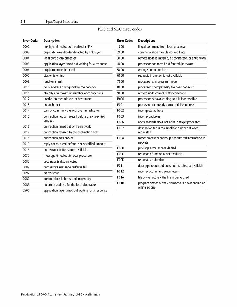
PLC and SLC error codes
Error Code: Description:
0002 link layer timed out or received a NAK
0003 duplicate token holder detected by link layer
0004 local port is disconnected
0005 application layer timed out waiting for a response
0006 duplicate node detected
0007 station is offline
0008 hardware fault
0010 no IP address configured for the network
0011 already at a maximum number of connections
0012 invalid internet address or host name
0013 no such host
0014 cannot communicate with the named server
0015 connection not completed before user-specified timeout
0016 connection timed out by the network
0017 connection refused by the destination host
0018 connection was broken
0019 reply not received before user-specified timeout
001A no network buffer space available
0037 message timed out in local processor
0083 processor is disconnected
0089 processor’s message buffer is full
0092 no response
00D3 control block is formatted incorrectly
00D5 incorrect address for the local data table
0500 application layer timed out waiting for a response
1000 illegal command from local processor
2000 communication module not working
3000 remote node is missing, disconnected, or shut down
4000 processor connected but faulted (hardware)
5000 wrong station number
6000 requested function is not available
7000 processor is in program mode
8000 processor’s compatibility file does not exist
9000 remote node cannot buffer command
B000 processor is downloading so it is inaccessible
F001 processor incorrectly converted the address
F002 incomplete address
F003 incorrect address
F006 addressed file does not exist in target processor
F007 destination file is too small for number of words requested
F00A target processor cannot put requested information in packets
F00B privilege error, access denied
F00C requested function is not available
F00D request is redundant
F011 data type requested does not match data available
F012 incorrect command parameters
F01A file owner active - the file is being used
F01B program owner active - someone is downloading or online editing
Error Code: Description:
Publication 1756-6.4.1 review January 1998 - preliminary
Input/Output Instructions 3-7
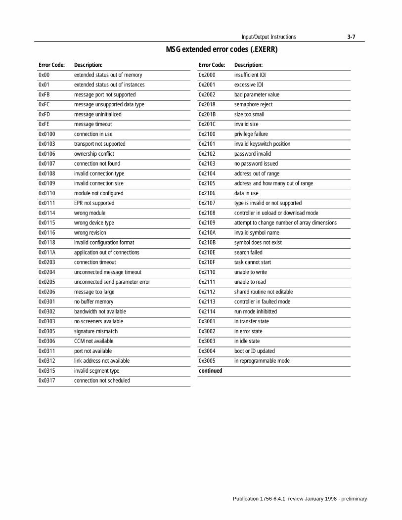
MSG extended error codes (.EXERR)
Error Code: Description:
0x00 extended status out of memory
0x01 extended status out of instances
0xFB message port not supported
0xFC message unsupported data type
0xFD message uninitialized
0xFE message timeout
0x0100 connection in use
0x0103 transport not supported
0x0106 ownership conflict
0x0107 connection not found
0x0108 invalid connection type
0x0109 invalid connection size
0x0110 module not configured
0x0111 EPR not supported
0x0114 wrong module
0x0115 wrong device type
0x0116 wrong revision
0x0118 invalid configuration format
0x011A application out of connections
0x0203 connection timeout
0x0204 unconnected message timeout
0x0205 unconnected send parameter error
0x0206 message too large
0x0301 no buffer memory
0x0302 bandwidth not available
0x0303 no screeners available
0x0305 signature mismatch
0x0306 CCM not available
0x0311 port not available
0x0312 link address not available
0x0315 invalid segment type
0x0317 connection not scheduled
0x2000 insufficient IOI
0x2001 excessive IOI
0x2002 bad parameter value
0x2018 semaphore reject
0x201B size too small
0x201C invalid size
0x2100 privilege failure
0x2101 invalid keyswitch position
0x2102 password invalid
0x2103 no password issued
0x2104 address out of range
0x2105 address and how many out of range
0x2106 data in use
0x2107 type is invalid or not supported
0x2108 controller in uoload or download mode
0x2109 attempt to change number of array dimensions
0x210A invalid symbol name
0x210B symbol does not exist
0x210E search failed
0x210F task cannot start
0x2110 unable to write
0x2111 unable to read
0x2112 shared routine not editable
0x2113 controller in faulted mode
0x2114 run mode inhibitted
0x3001 in transfer state
0x3002 in error state
0x3003 in idle state
0x3004 boot or ID updated
0x3005 in reprogrammable mode
continued
Error Code: Description:
Publication 1756-6.4.1 review January 1998 - preliminary
3-8 Input/Output Instructions
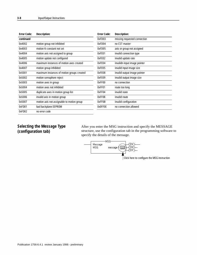
Selecting the Message Type(configuration tab)
After you enter the MSG instruction and specify the MESSAGE structure, use the configuration tab in the programming software to specify the details of the message.
Error Code: Description:
continued
0x4002 motion group not inhibited
0x4003 motion K-constant not set
0x4004 motion axis not assigned to group
0x4005 motion update not configured
0x4006 maximum instances of motion axes created
0x4007 motion group inhibited
0x5001 maximum instances of motion groups created
0x5002 motion semaphore reject
0x5003 motion axes in group
0x5004 motion axes not inhibited
0x5005 duplicate axes in motion group list
0x5006 invalid axis in motion group
0x5007 motion axis not assignable to motion group
0xFD01 bad backplane EEPROM
0xFD02 no error code
0xFD03 missing requested connection
0xFD04 no CST master
0xFD05 axis or group not assigned
0xFE01 invalid connection type
0xFE02 invalid update rate
0xFE04 invalidn input image pointer
0xFE05 invalid input image size
0xFE08 invalid output image pointer
0xFE09 invalid output image size
0xFF00 no connection
0xFF01 route too long
0xFF04 invalid state
0xFF08 invalid route
0xFF0B invalid configuration
0x0FF0E no connection allowed
Error Code: Description:
Click here to configure the MSG instruction
Publication 1756-6.4.1 review January 1998 - preliminary
Input/Output Instructions 3-9
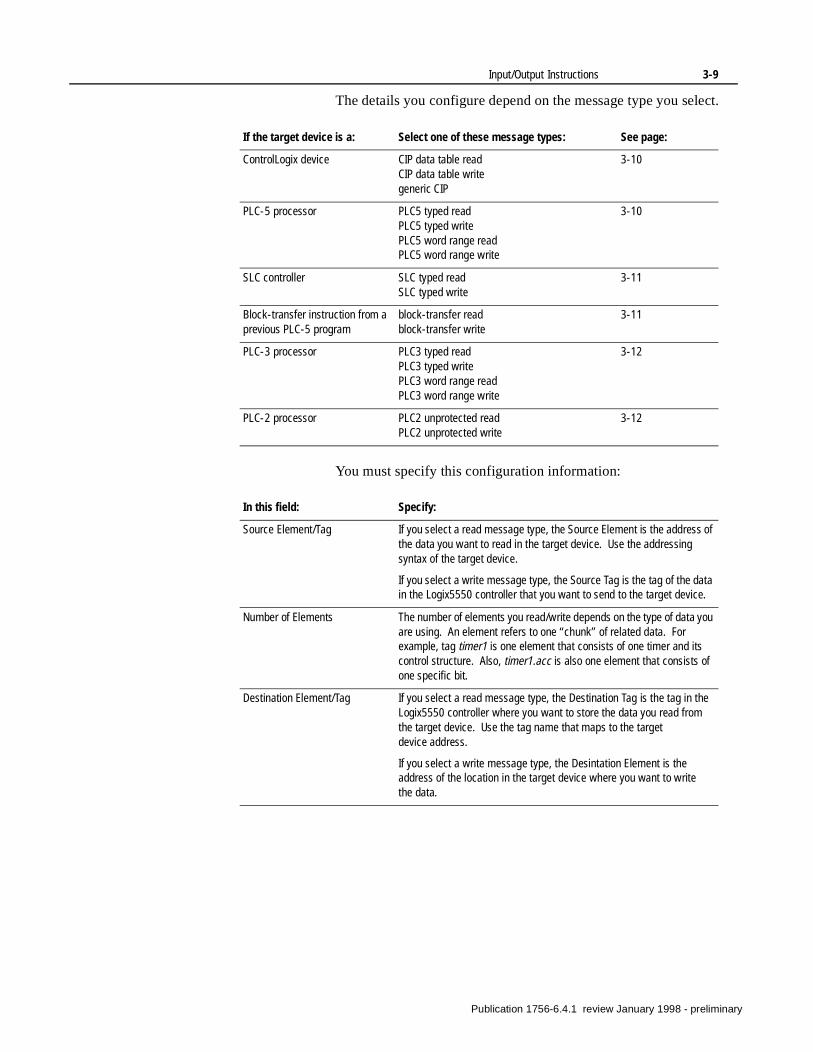
The details you configure depend on the message type you select.
You must specify this configuration information:
If the target device is a: Select one of these message types: See page:
ControlLogix device CIP data table readCIP data table writegeneric CIP
3-10
PLC-5 processor PLC5 typed readPLC5 typed writePLC5 word range readPLC5 word range write
3-10
SLC controller SLC typed readSLC typed write
3-11
Block-transfer instruction from a previous PLC-5 program
block-transfer readblock-transfer write
3-11
PLC-3 processor PLC3 typed readPLC3 typed writePLC3 word range readPLC3 word range write
3-12
PLC-2 processor PLC2 unprotected readPLC2 unprotected write
3-12
In this field: Specify:
Source Element/Tag If you select a read message type, the Source Element is the address of the data you want to read in the target device. Use the addressing syntax of the target device.
If you select a write message type, the Source Tag is the tag of the data in the Logix5550 controller that you want to send to the target device.
Number of Elements The number of elements you read/write depends on the type of data you are using. An element refers to one “chunk” of related data. For example, tag timer1 is one element that consists of one timer and its control structure. Also, timer1.acc is also one element that consists of one specific bit.
Destination Element/Tag If you select a read message type, the Destination Tag is the tag in the Logix5550 controller where you want to store the data you read from the target device. Use the tag name that maps to the target device address.
If you select a write message type, the Desintation Element is the address of the location in the target device where you want to write the data.
Publication 1756-6.4.1 review January 1998 - preliminary
3-10 Input/Output Instructions
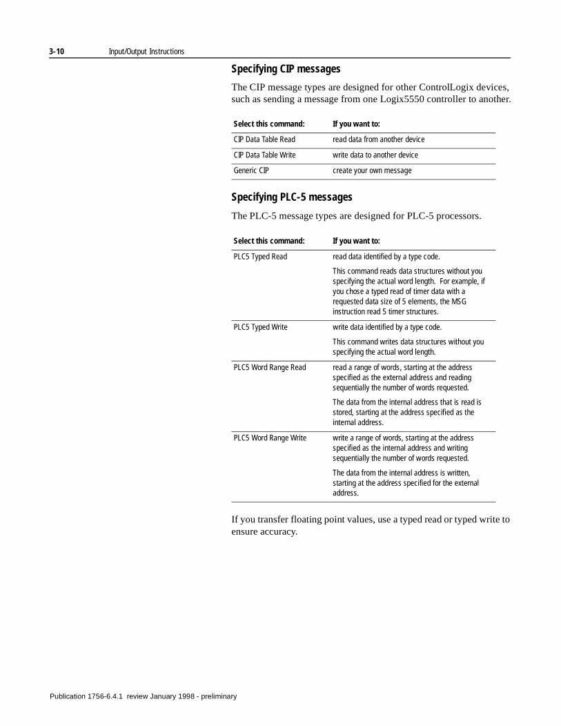
Specifying CIP messages
The CIP message types are designed for other ControlLogix devices, such as sending a message from one Logix5550 controller to another.
Specifying PLC-5 messages
The PLC-5 message types are designed for PLC-5 processors.
If you transfer floating point values, use a typed read or typed write to ensure accuracy.
Select this command: If you want to:
CIP Data Table Read read data from another device
CIP Data Table Write write data to another device
Generic CIP create your own message
Select this command: If you want to:
PLC5 Typed Read read data identified by a type code.
This command reads data structures without you specifying the actual word length. For example, if you chose a typed read of timer data with a requested data size of 5 elements, the MSG instruction read 5 timer structures.
PLC5 Typed Write write data identified by a type code.
This command writes data structures without you specifying the actual word length.
PLC5 Word Range Read read a range of words, starting at the address specified as the external address and reading sequentially the number of words requested.
The data from the internal address that is read is stored, starting at the address specified as the internal address.
PLC5 Word Range Write write a range of words, starting at the address specified as the internal address and writing sequentially the number of words requested.
The data from the internal address is written, starting at the address specified for the external address.
Publication 1756-6.4.1 review January 1998 - preliminary
Input/Output Instructions 3-11
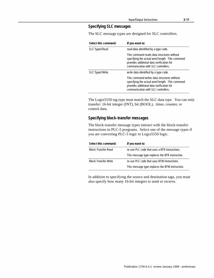
Specifying SLC messages
The SLC message types are designed for SLC controllers.
The Logix5550 tag type must match the SLC data type. You can only transfer: 16-bit integer (INT), bit (BOOL), timer, counter, or control data.
Specifying block-transfer messages
The block-transfer message types interact with the block-transfer instructions in PLC-5 programs. Select one of the message types if you are converting PLC-5 logic to Logix5550 logic.
In addition to specifying the source and destination tags, you must also specify how many 16-bit integers to send or receive.
Select this command: If you want to:
SLC Typed Read read data identified by a type code.
This command reads data structures without specifying the actual word length. This command provides additional data verification for communication with SLC controllers.
SLC Typed Write write data identified by a type code.
This command writes data structures without specifying the actual word length. This command provides additional data verification for communication with SLC controllers.
Select this command: If you want to:
Block-Transfer Read re-use PLC code that uses a BTR instructions.
This message type replaces the BTR instruction.
Block-Transfer Write re-use PLC code that uses BTW instructions.
This message type replaces the BTW instruction.
Publication 1756-6.4.1 review January 1998 - preliminary
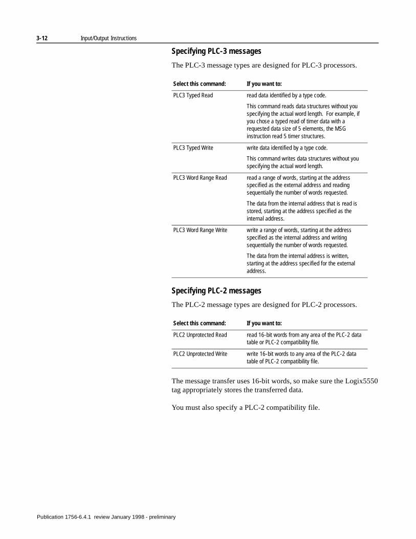
3-12 Input/Output Instructions
Specifying PLC-3 messages
The PLC-3 message types are designed for PLC-3 processors.
Specifying PLC-2 messages
The PLC-2 message types are designed for PLC-2 processors.
The message transfer uses 16-bit words, so make sure the Logix5550 tag appropriately stores the transferred data.
You must also specify a PLC-2 compatibility file.
Select this command: If you want to:
PLC3 Typed Read read data identified by a type code.
This command reads data structures without you specifying the actual word length. For example, if you chose a typed read of timer data with a requested data size of 5 elements, the MSG instruction read 5 timer structures.
PLC3 Typed Write write data identified by a type code.
This command writes data structures without you specifying the actual word length.
PLC3 Word Range Read read a range of words, starting at the address specified as the external address and reading sequentially the number of words requested.
The data from the internal address that is read is stored, starting at the address specified as the internal address.
PLC3 Word Range Write write a range of words, starting at the address specified as the internal address and writing sequentially the number of words requested.
The data from the internal address is written, starting at the address specified for the external address.
Select this command: If you want to:
PLC2 Unprotected Read read 16-bit words from any area of the PLC-2 data table or PLC-2 compatibility file.
PLC2 Unprotected Write write 16-bit words to any area of the PLC-2 data table of PLC-2 compatibility file.
Publication 1756-6.4.1 review January 1998 - preliminary
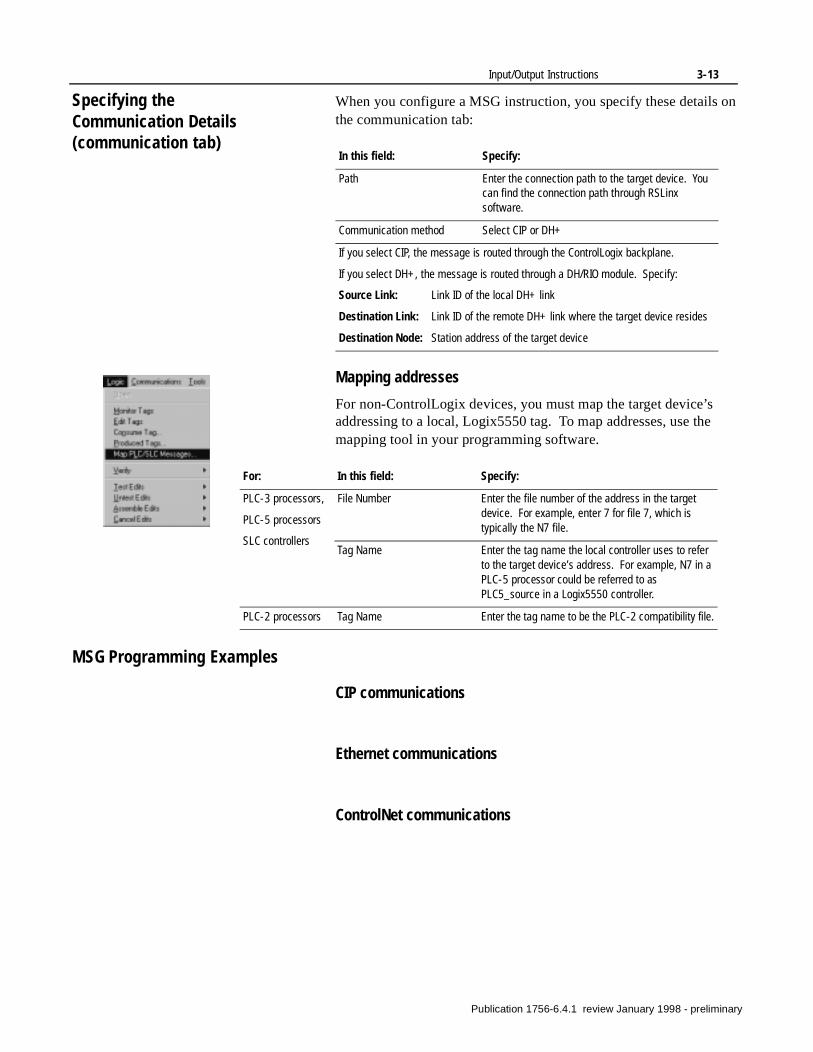
Input/Output Instructions 3-13
Specifying the Communication Details(communication tab)
When you configure a MSG instruction, you specify these details on the communication tab:
Mapping addresses
For non-ControlLogix devices, you must map the target device’s addressing to a local, Logix5550 tag. To map addresses, use themapping tool in your programming software.
MSG Programming Examples
CIP communications
Ethernet communications
ControlNet communications
In this field: Specify:
Path Enter the connection path to the target device. You can find the connection path through RSLinx software.
Communication method Select CIP or DH+
If you select CIP, the message is routed through the ControlLogix backplane.
If you select DH+, the message is routed through a DH/RIO module. Specify:
Source Link: Link ID of the local DH+ link
Destination Link: Link ID of the remote DH+ link where the target device resides
Destination Node: Station address of the target device
For: In this field: Specify:
PLC-3 processors,
PLC-5 processors
SLC controllers
File Number Enter the file number of the address in the target device. For example, enter 7 for file 7, which is typically the N7 file.
Tag Name Enter the tag name the local controller uses to refer to the target device’s address. For example, N7 in a PLC-5 processor could be referred to as PLC5_source in a Logix5550 controller.
PLC-2 processors Tag Name Enter the tag name to be the PLC-2 compatibility file.
Publication 1756-6.4.1 review January 1998 - preliminary
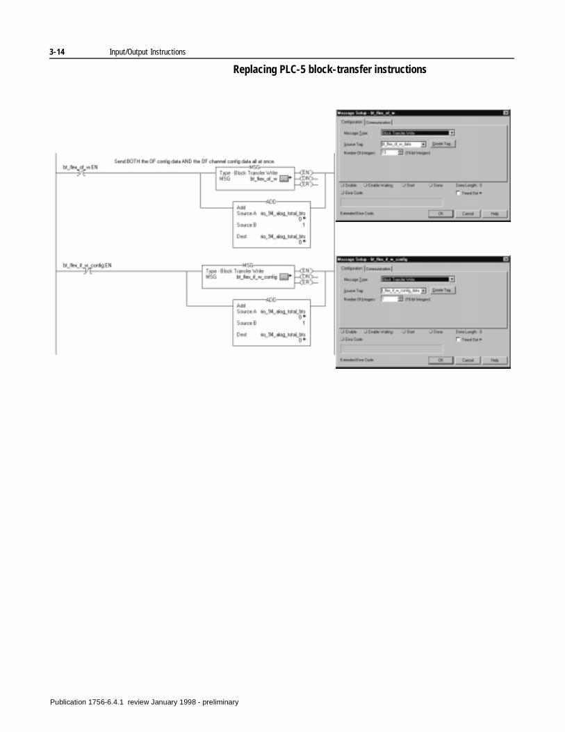
3-14 Input/Output Instructions
Replacing PLC-5 block-transfer instructions
Publication 1756-6.4.1 review January 1998 - preliminary
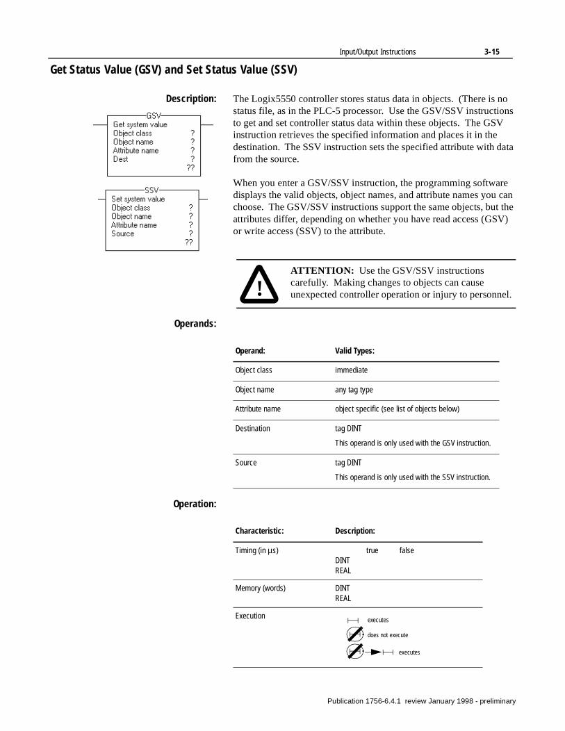
Input/Output Instructions 3-15
Get Status Value (GSV) and Set Status Value (SSV)
Description: The Logix5550 controller stores status data in objects. (There is no status file, as in the PLC-5 processor. Use the GSV/SSV instructions to get and set controller status data within these objects. The GSV instruction retrieves the specified information and places it in the destination. The SSV instruction sets the specified attribute with data from the source.
When you enter a GSV/SSV instruction, the programming software displays the valid objects, object names, and attribute names you can choose. The GSV/SSV instructions support the same objects, but the attributes differ, depending on whether you have read access (GSV) or write access (SSV) to the attribute.
Operands:
Operation:
!ATTENTION: Use the GSV/SSV instructions carefully. Making changes to objects can cause unexpected controller operation or injury to personnel.
Operand: Valid Types:
Object class immediate
Object name any tag type
Attribute name object specific (see list of objects below)
Destination tag DINT
This operand is only used with the GSV instruction.
Source tag DINT
This operand is only used with the SSV instruction.
Characteristic: Description:
Timing (in µs) true falseDINTREAL
Memory (words) DINTREAL
Execution executes
does not execute
executes
Publication 1756-6.4.1 review January 1998 - preliminary
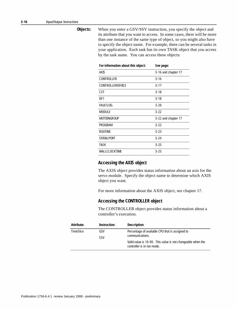
3-16 Input/Output Instructions
Objects: When you enter a GSV/SSV instruction, you specify the object and its attribute that you want to access. In some cases, there will be more than one instance of the same type of object, so you might also have to specify the object name. For example, there can be several tasks in your application. Each task has its own TASK object that you access by the task name. You can access these objects:
Accessing the AXIS object
The AXIS object provides status information about an axis for the servo module. Specify the object name to determine which AXIS object you want.
For more information about the AXIS object, see chapter 17.
Accessing the CONTROLLER object
The CONTROLLER object provides status information about a controller’s execution.
For information about this object: See page:
AXIS 3-16 and chapter 17
CONTROLLER 3-16
CONTROLLERDEVICE 3-17
CST 3-18
DF1 3-18
FAULTLOG 3-20
MODULE 3-22
MOTIONGROUP 3-22 and chapter 17
PROGRAM 3-22
ROUTINE 3-23
SERIALPORT 3-24
TASK 3-25
WALLCLOCKTIME 3-25
Attribute: Instruction: Description:
TimeSlice GSV
SSV
Percentage of available CPU that is assigned to communications.
Valid value is 10-90. This value is not changeable when the controller is in run mode.
Publication 1756-6.4.1 review January 1998 - preliminary
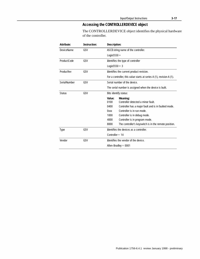
Input/Output Instructions 3-17
Accessing the CONTROLLERDEVICE object
The CONTROLLERDEVICE object identifies the physical hardware of the controller.
Attribute: Instruction: Description:
DeviceName GSV ASCII string name of the controller.
Logix5550 =
ProductCode GSV Identifies the type of controller
Logix5550 = 3
ProducRev GSV Identifies the current product revision.
For a controller, this value starts at series A (1), revision A (1).
SerialNumber GSV Serial number of the device.
The serial number is assigned when the device is built.
Status GSV Bits identify status:
Value: Meaning:0100 Controller detected a minor fault.
0400 Controller has a major fault and is in faulted mode.
0xxx Controller is in run mode.
1000 Controller is in debug mode.
4000 Controller is in program mode.
8000 The controller’s keyswitch is in the remote position.
Type GSV Identifies the devices as a controller.
Controller = 14
Vendor GSV Identifies the vendor of the device.
Allen-Bradley = 0001
Publication 1756-6.4.1 review January 1998 - preliminary
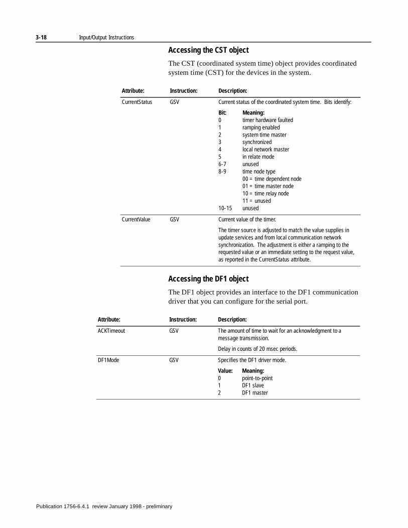
3-18 Input/Output Instructions
Accessing the CST object
The CST (coordinated system time) object provides coordinated system time (CST) for the devices in the system.
Accessing the DF1 object
The DF1 object provides an interface to the DF1 communication driver that you can configure for the serial port.
Attribute: Instruction: Description:
CurrentStatus GSV Current status of the coordinated system time. Bits identify:
Bit: Meaning:0 timer hardware faulted1 ramping enabled2 system time master3 synchronized4 local network master5 in relate mode6-7 unused8-9 time node type
00 = time dependent node01 = time master node10 = time relay node11 = unused
10-15 unused
CurrentValue GSV Current value of the timer.
The timer source is adjusted to match the value supplies in update services and from local communication network synchronization. The adjustment is either a ramping to the requested value or an immediate setting to the request value, as reported in the CurrentStatus attribute.
Attribute: Instruction: Description:
ACKTimeout GSV The amount of time to wait for an acknowledgment to a message transmission.
Delay in counts of 20 msec periods.
DF1Mode GSV Specifies the DF1 driver mode.
Value: Meaning:0 point-to-point1 DF1 slave2 DF1 master
Publication 1756-6.4.1 review January 1998 - preliminary
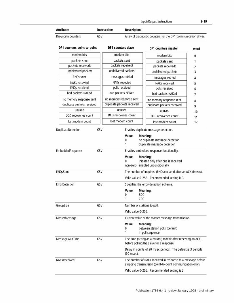
Input/Output Instructions 3-19
DiagnosticCounters GSV Array of diagnostic counters for the DF1 communication driver.
DuplicateDetection GSV Enables duplicate message detection.
Value: Meaning:0 no duplicate message detection1 duplicate message detection
EmbeddedResponse GSV Enables embedded response functionality.
Value: Meaning:0 initiated only after one is receivednon-zero enabled unconditionally
ENQsSent GSV The number of inquiries (ENQs) to send after an ACK timeout.
Valid value 0-255. Recommended setting is 3.
ErrorDetection GSV Specifies the error-detection scheme.
Value: Meaning:0 BCC1 CRC
GroupSize GSV Number of stations to poll.
Valid value 0-255.
MasterMessage GSV Current value of the master message transmission.
Value: Meaning:0 between station polls (default)1 in poll sequence
MessageWaitTime GSV The time (acting as a master) to wait after receiving an ACK before polling the slave for a response.
Delay in counts of 20 msec periods. The default is 3 periods (60 msec).
NAKsReceived GSV The number of NAKs received in response to a message before stopping transmission (point-to-point communication only).
Valid value 0-255. Recommended setting is 3.
Attribute: Instruction: Description:
modem bits
DF1 counters point-to-point
packets sent
NAKs recevied
0
1
2
5
6
7
4
ENQs received
bad packets NAKed
word
3
packets receivedt
undelivered packets
ENQs sent
9
10
11
8
12
no memory response sent
duplicate packets received
unused
DCD recoveries count
lost modem count
modem bits
packets sent
NAKs recevied
polls received
bad packets NAKed
packets receivedt
undelivered packets
messages retried
no memory response sent
duplicate packets received
unused
DCD recoveries count
lost modem count
DF1 counters slave DF1 counters master
modem bits
packets sent
NAKs recevied
polls received
bad packets NAKed
packets receivedt
undelivered packets
messages retried
no memory response sent
duplicate packets received
unused
DCD recoveries count
lost modem count
Publication 1756-6.4.1 review January 1998 - preliminary
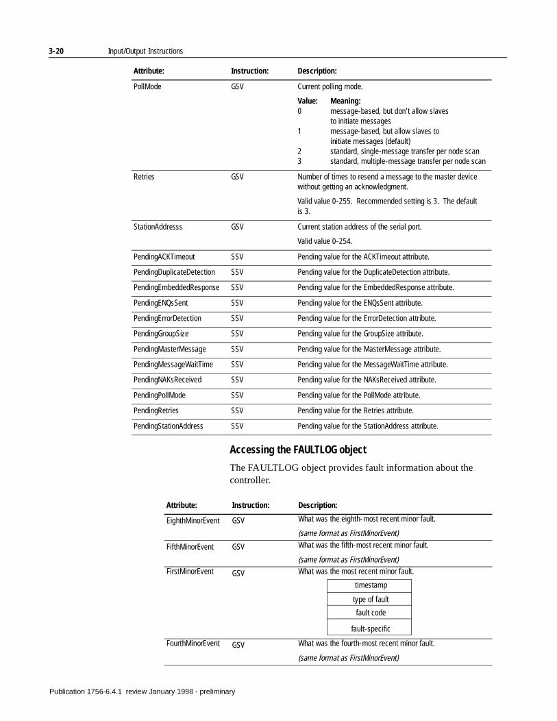
3-20 Input/Output Instructions
Accessing the FAULTLOG object
The FAULTLOG object provides fault information about the controller.
PollMode GSV Current polling mode.
Value: Meaning:0 message-based, but don’t allow slaves
to initiate messages1 message-based, but allow slaves to
initiate messages (default)2 standard, single-message transfer per node scan3 standard, multiple-message transfer per node scan
Retries GSV Number of times to resend a message to the master device without getting an acknowledgment.
Valid value 0-255. Recommended setting is 3. The default is 3.
StationAddresss GSV Current station address of the serial port.
Valid value 0-254.
PendingACKTimeout SSV Pending value for the ACKTimeout attribute.
PendingDuplicateDetection SSV Pending value for the DuplicateDetection attribute.
PendingEmbeddedResponse SSV Pending value for the EmbeddedResponse attribute.
PendingENQsSent SSV Pending value for the ENQsSent attribute.
PendingErrorDetection SSV Pending value for the ErrorDetection attribute.
PendingGroupSize SSV Pending value for the GroupSize attribute.
PendingMasterMessage SSV Pending value for the MasterMessage attribute.
PendingMessageWaitTime SSV Pending value for the MessageWaitTime attribute.
PendingNAKsReceived SSV Pending value for the NAKsReceived attribute.
PendingPollMode SSV Pending value for the PollMode attribute.
PendingRetries SSV Pending value for the Retries attribute.
PendingStationAddress SSV Pending value for the StationAddress attribute.
Attribute: Instruction: Description:
EighthMinorEvent GSV What was the eighth-most recent minor fault.
(same format as FirstMinorEvent)
FifthMinorEvent GSV What was the fifth-most recent minor fault.
(same format as FirstMinorEvent)FirstMinorEvent GSV What was the most recent minor fault.
FourthMinorEvent GSV What was the fourth-most recent minor fault.
(same format as FirstMinorEvent)
Attribute: Instruction: Description:
timestamp
type of fault
fault code
fault-specific
Publication 1756-6.4.1 review January 1998 - preliminary
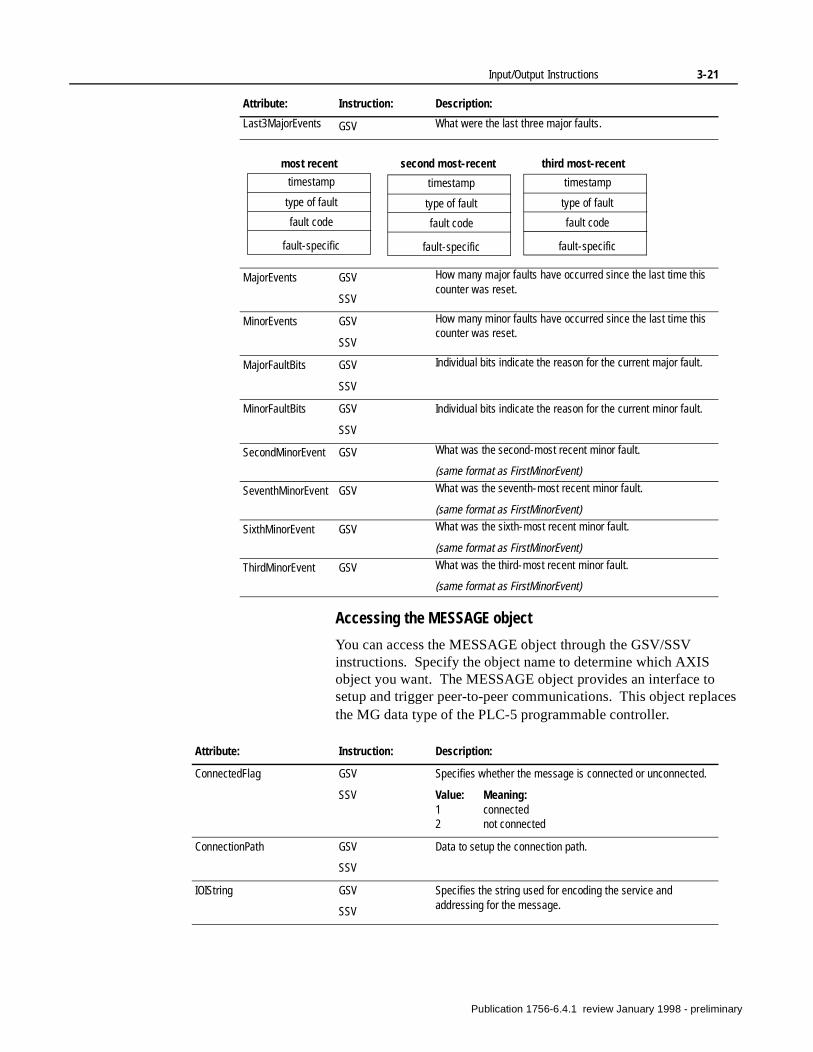
Input/Output Instructions 3-21
Accessing the MESSAGE object
You can access the MESSAGE object through the GSV/SSV instructions. Specify the object name to determine which AXIS object you want. The MESSAGE object provides an interface to setup and trigger peer-to-peer communications. This object replaces the MG data type of the PLC-5 programmable controller.
Last3MajorEvents GSV What were the last three major faults.
MajorEvents GSV
SSV
How many major faults have occurred since the last time this counter was reset.
MinorEvents GSV
SSV
How many minor faults have occurred since the last time this counter was reset.
MajorFaultBits GSV
SSV
Individual bits indicate the reason for the current major fault.
MinorFaultBits GSV
SSV
Individual bits indicate the reason for the current minor fault.
SecondMinorEvent GSV What was the second-most recent minor fault.
(same format as FirstMinorEvent)
SeventhMinorEvent GSV What was the seventh-most recent minor fault.
(same format as FirstMinorEvent)
SixthMinorEvent GSV What was the sixth-most recent minor fault.
(same format as FirstMinorEvent)
ThirdMinorEvent GSV What was the third-most recent minor fault.
(same format as FirstMinorEvent)
Attribute: Instruction: Description:
ConnectedFlag GSV
SSV
Specifies whether the message is connected or unconnected.
Value: Meaning:1 connected2 not connected
ConnectionPath GSV
SSV
Data to setup the connection path.
IOIString GSV
SSV
Specifies the string used for encoding the service and addressing for the message.
Attribute: Instruction: Description:
timestamp
most recent
type of fault
fault code
fault-specific
second most-recent third most-recent
timestamp
type of fault
fault code
fault-specific
timestamp
type of fault
fault code
fault-specific
Publication 1756-6.4.1 review January 1998 - preliminary
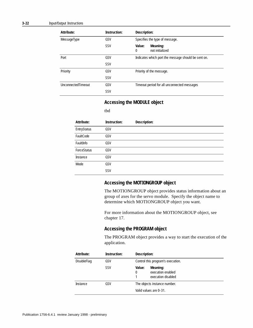
3-22 Input/Output Instructions
Accessing the MODULE object
tbd
Accessing the MOTIONGROUP object
The MOTIONGROUP object provides status information about an group of axes for the servo module. Specify the object name to determine which MOTIONGROUP object you want.
For more information about the MOTIONGROUP object, see chapter 17.
Accessing the PROGRAM object
The PROGRAM object provides a way to start the execution of the application.
MessageType GSV
SSV
Specifies the type of message.
Value: Meaning:0 not initialized
Port GSV
SSV
Indicates which port the message should be sent on.
Priority GSV
SSV
Priority of the message.
UnconnectedTimeout GSV
SSV
Timeout period for all unconnected messages
Attribute: Instruction: Description:
EntryStatus GSV
FaultCode GSV
FaultInfo GSV
ForceStatus GSV
Instance GSV
Mode GSV
SSV
Attribute: Instruction: Description:
DisableFlag GSV
SSV
Control this program’s execution.
Value: Meaning:0 execution enabled1 execution disabled
Instance GSV The objects instance number.
Valid values are 0-31.
Attribute: Instruction: Description:
Publication 1756-6.4.1 review January 1998 - preliminary
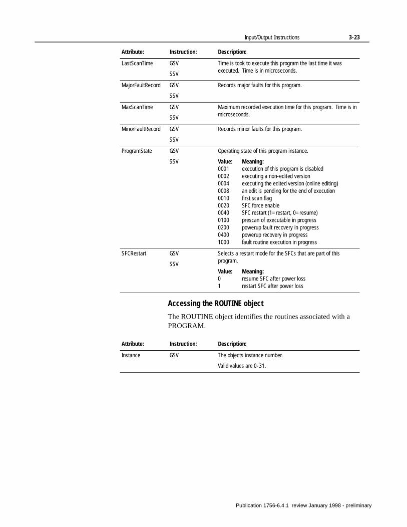
Input/Output Instructions 3-23
Accessing the ROUTINE object
The ROUTINE object identifies the routines associated with a PROGRAM.
LastScanTime GSV
SSV
Time is took to execute this program the last time it was executed. Time is in microseconds.
MajorFaultRecord GSV
SSV
Records major faults for this program.
MaxScanTime GSV
SSV
Maximum recorded execution time for this program. Time is in microseconds.
MinorFaultRecord GSV
SSV
Records minor faults for this program.
ProgramState GSV
SSV
Operating state of this program instance.
Value: Meaning:0001 execution of this program is disabled0002 executing a non-edited version0004 executing the edited version (online editing)0008 an edit is pending for the end of execution0010 first scan flag0020 SFC force enable0040 SFC restart (1=restart, 0=resume)0100 prescan of executable in progress0200 powerup fault recovery in progress0400 powerup recovery in progress1000 fault routine execution in progress
SFCRestart GSV
SSV
Selects a restart mode for the SFCs that are part of this program.
Value: Meaning:0 resume SFC after power loss1 restart SFC after power loss
Attribute: Instruction: Description:
Instance GSV The objects instance number.
Valid values are 0-31.
Attribute: Instruction: Description:
Publication 1756-6.4.1 review January 1998 - preliminary
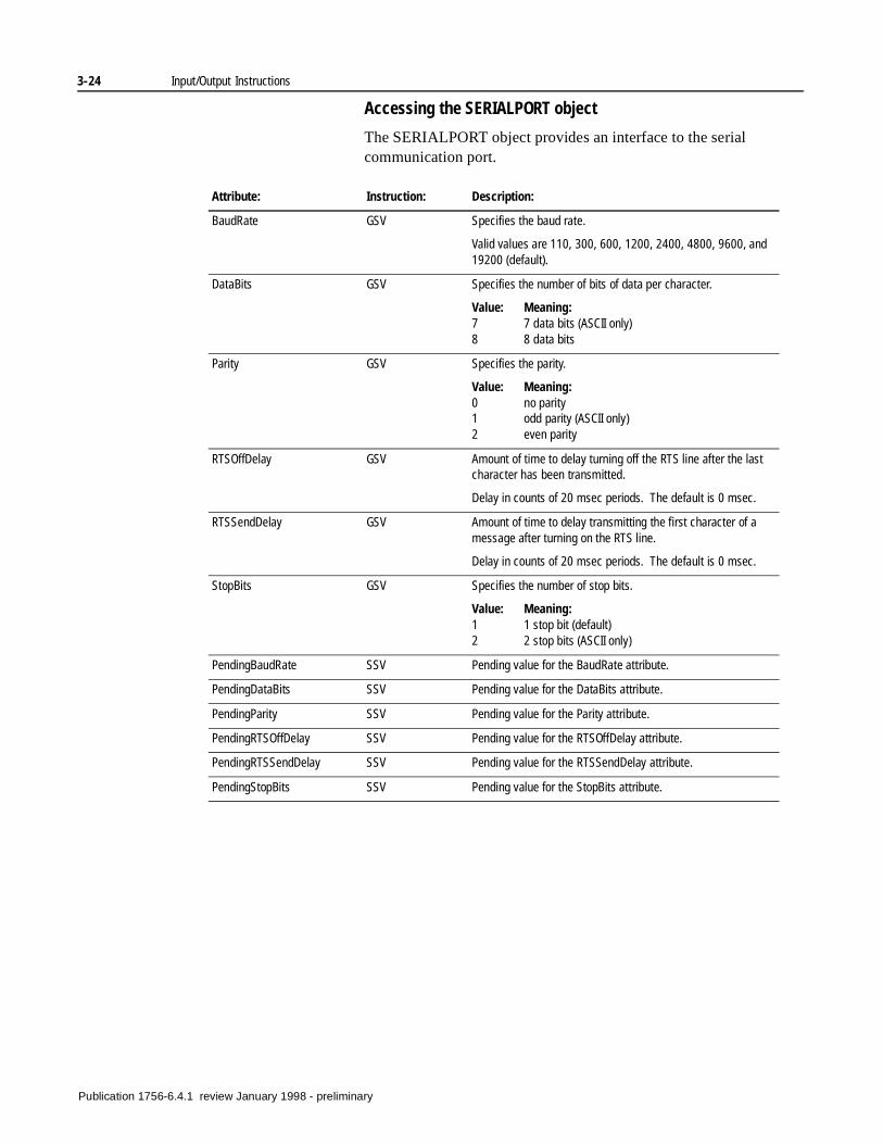
3-24 Input/Output Instructions
Accessing the SERIALPORT object
The SERIALPORT object provides an interface to the serial communication port.
Attribute: Instruction: Description:
BaudRate GSV Specifies the baud rate.
Valid values are 110, 300, 600, 1200, 2400, 4800, 9600, and 19200 (default).
DataBits GSV Specifies the number of bits of data per character.
Value: Meaning:7 7 data bits (ASCII only)8 8 data bits
Parity GSV Specifies the parity.
Value: Meaning:0 no parity1 odd parity (ASCII only)2 even parity
RTSOffDelay GSV Amount of time to delay turning off the RTS line after the last character has been transmitted.
Delay in counts of 20 msec periods. The default is 0 msec.
RTSSendDelay GSV Amount of time to delay transmitting the first character of a message after turning on the RTS line.
Delay in counts of 20 msec periods. The default is 0 msec.
StopBits GSV Specifies the number of stop bits.
Value: Meaning:1 1 stop bit (default)2 2 stop bits (ASCII only)
PendingBaudRate SSV Pending value for the BaudRate attribute.
PendingDataBits SSV Pending value for the DataBits attribute.
PendingParity SSV Pending value for the Parity attribute.
PendingRTSOffDelay SSV Pending value for the RTSOffDelay attribute.
PendingRTSSendDelay SSV Pending value for the RTSSendDelay attribute.
PendingStopBits SSV Pending value for the StopBits attribute.
Publication 1756-6.4.1 review January 1998 - preliminary
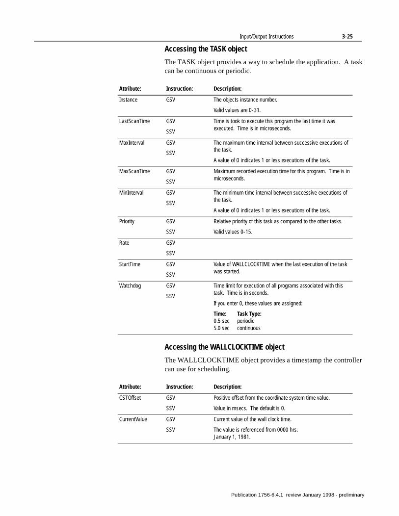
Input/Output Instructions 3-25
Accessing the TASK object
The TASK object provides a way to schedule the application. A task can be continuous or periodic.
Accessing the WALLCLOCKTIME object
The WALLCLOCKTIME object provides a timestamp the controller can use for scheduling.
Attribute: Instruction: Description:
Instance GSV The objects instance number.
Valid values are 0-31.
LastScanTime GSV
SSV
Time is took to execute this program the last time it was executed. Time is in microseconds.
MaxInterval GSV
SSV
The maximum time interval between successive executions of the task.
A value of 0 indicates 1 or less executions of the task.
MaxScanTime GSV
SSV
Maximum recorded execution time for this program. Time is in microseconds.
MinInterval GSV
SSV
The minimum time interval between successive executions of the task.
A value of 0 indicates 1 or less executions of the task.
Priority GSV
SSV
Relative priority of this task as compared to the other tasks.
Valid values 0-15.
Rate GSV
SSV
StartTime GSV
SSV
Value of WALLCLOCKTIME when the last execution of the task was started.
Watchdog GSV
SSV
Time limit for execution of all programs associated with this task. Time is in seconds.
If you enter 0, these values are assigned:
Time: Task Type:0.5 sec periodic5.0 sec continuous
Attribute: Instruction: Description:
CSTOffset GSV
SSV
Positive offset from the coordinate system time value.
Value in msecs. The default is 0.
CurrentValue GSV
SSV
Current value of the wall clock time.
The value is referenced from 0000 hrs.January 1, 1981.
Publication 1756-6.4.1 review January 1998 - preliminary
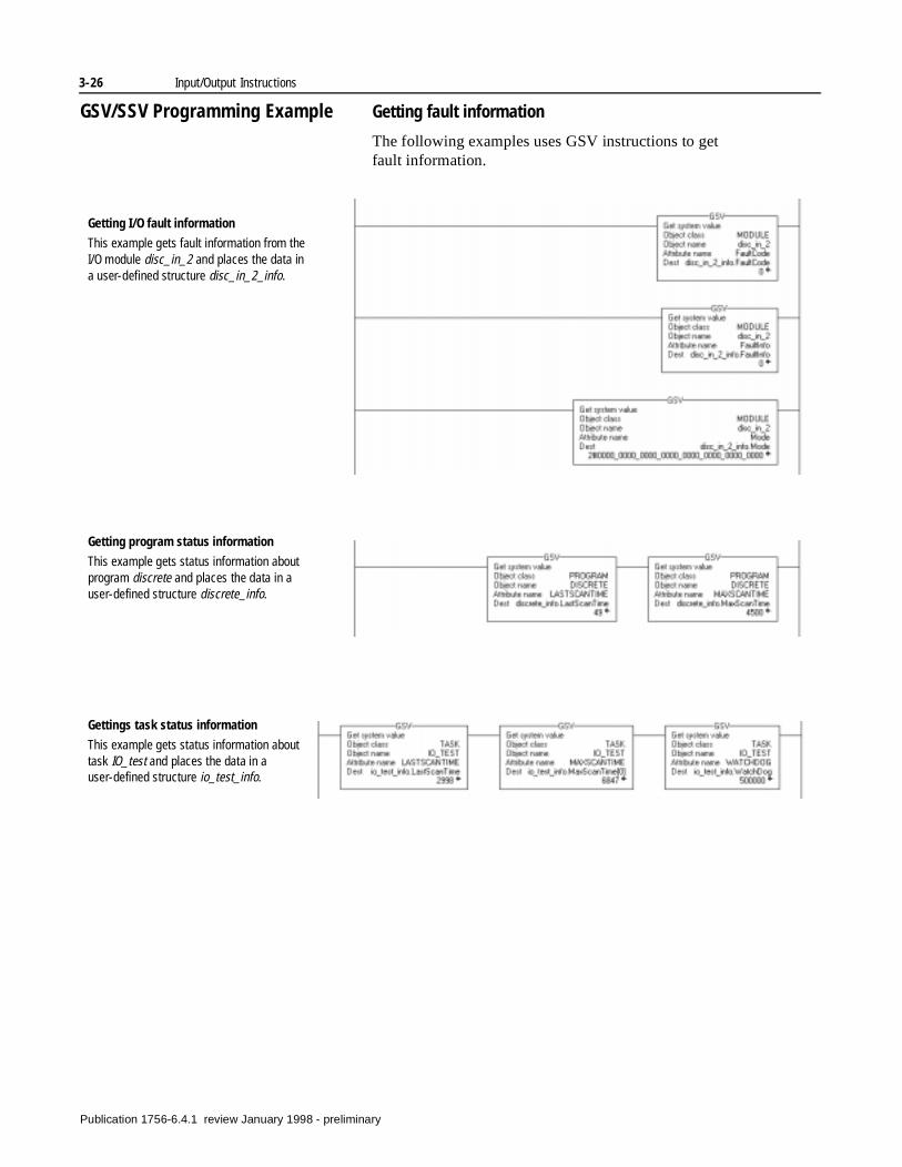
3-26 Input/Output Instructions
GSV/SSV Programming Example Getting fault information
The following examples uses GSV instructions to get fault information.
Getting I/O fault information
This example gets fault information from the I/O module disc_in_2 and places the data in a user-defined structure disc_in_2_info.
Getting program status information
This example gets status information about program discrete and places the data in a user-defined structure discrete_info.
Gettings task status information
This example gets status information about task IO_test and places the data in a user-defined structure io_test_info.
Publication 1756-6.4.1 review January 1998 - preliminary
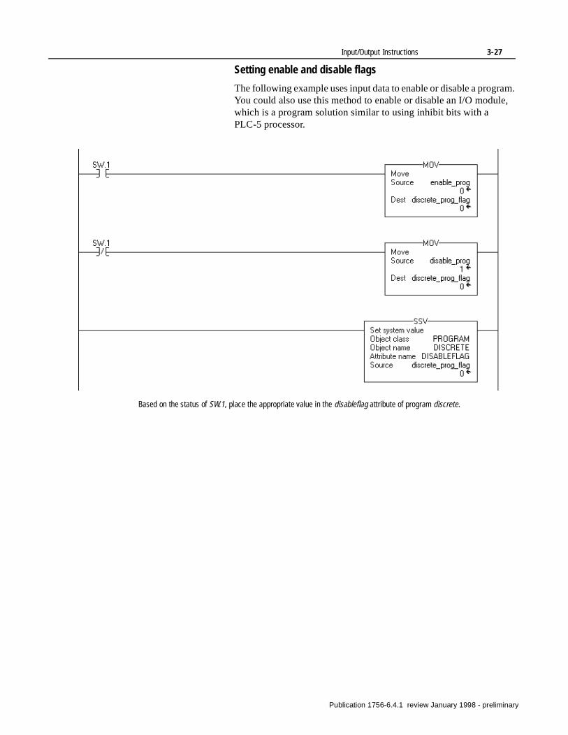
Input/Output Instructions 3-27
Setting enable and disable flags
The following example uses input data to enable or disable a program. You could also use this method to enable or disable an I/O module, which is a program solution similar to using inhibit bits with a PLC-5 processor.
Based on the status of SW.1, place the appropriate value in the disableflag attribute of program discrete.
Publication 1756-6.4.1 review January 1998 - preliminary

3-28 Input/Output Instructions
Notes:
Publication 1756-6.4.1 review January 1998 - preliminary
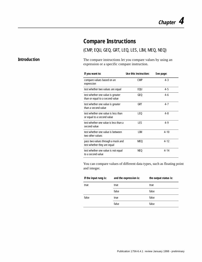
Chapter 4
Compare Instructions(CMP, EQU, GEQ, GRT, LEQ, LES, LIM, MEQ, NEQ)
Introduction The compare instructions let you compare values by using an expression or a specific compare instruction.
You can compare values of different data types, such as floating point and integer.
If you want to: Use this instruction: See page:
compare values based on an expression
CMP 4-3
test whether two values are equal EQU 4-5
test whether one value is greater than or equal to a second value
GEQ 4-6
test whether one value is greater than a second value
GRT 4-7
test whether one value is less than or equal to a second value
LEQ 4-8
test whether one value is less than a second value
LES 4-9
test whether one value is between two other values
LIM 4-10
pass two values through a mask and test whether they are equal
MEQ 4-12
test whether one value is not equal to a second value
NEQ 4-14
If the input rung is: and the expression is: the output status is:
true true true
false false
false true false
false false
Publication 1756-6.4.1 review January 1998 - preliminary
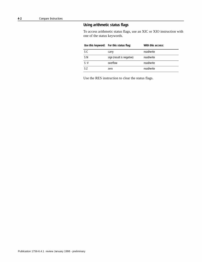
4-2 Compare Instructions
Using arithmetic status flags
To access arithmetic status flags, use an XIC or XIO instruction with one of the status keywords.
Use the RES instruction to clear the status flags.
Use this keyword: For this status flag: With this access:
S:C carry read/write
S:N sign (result is negative) read/write
S: V overflow read/write
S:Z zero read/write
Publication 1756-6.4.1 review January 1998 - preliminary
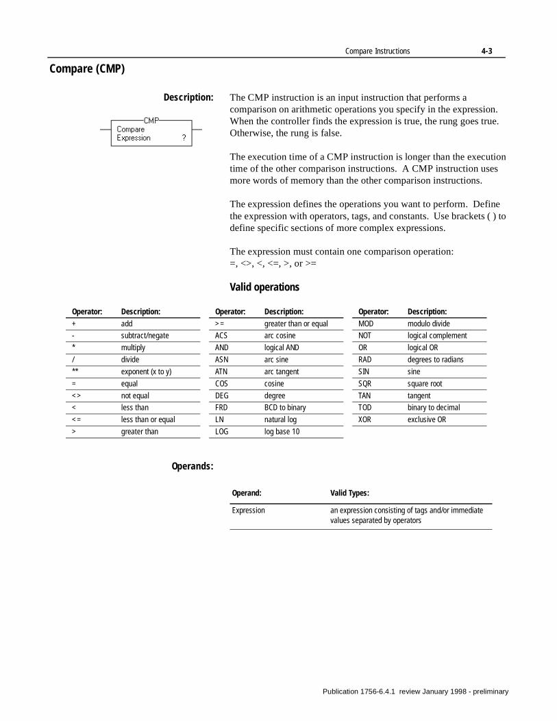
Compare Instructions 4-3
Compare (CMP)
Description: The CMP instruction is an input instruction that performs a comparison on arithmetic operations you specify in the expression. When the controller finds the expression is true, the rung goes true. Otherwise, the rung is false.
The execution time of a CMP instruction is longer than the execution time of the other comparison instructions. A CMP instruction uses more words of memory than the other comparison instructions.
The expression defines the operations you want to perform. Define the expression with operators, tags, and constants. Use brackets ( ) to define specific sections of more complex expressions.
The expression must contain one comparison operation: =, <>, <, <=, >, or >=
Valid operations
Operands:
Operator: Description:
+ add
- subtract/negate
* multiply
/ divide
** exponent (x to y)
= equal
<> not equal
< less than
<= less than or equal
> greater than
>= greater than or equal
ACS arc cosine
AND logical AND
ASN arc sine
ATN arc tangent
COS cosine
DEG degree
FRD BCD to binary
LN natural log
LOG log base 10
Operator: Description:
MOD modulo divide
NOT logical complement
OR logical OR
RAD degrees to radians
SIN sine
SQR square root
TAN tangent
TOD binary to decimal
XOR exclusive OR
Operator: Description:
Operand: Valid Types:
Expression an expression consisting of tags and/or immediate values separated by operators
Publication 1756-6.4.1 review January 1998 - preliminary
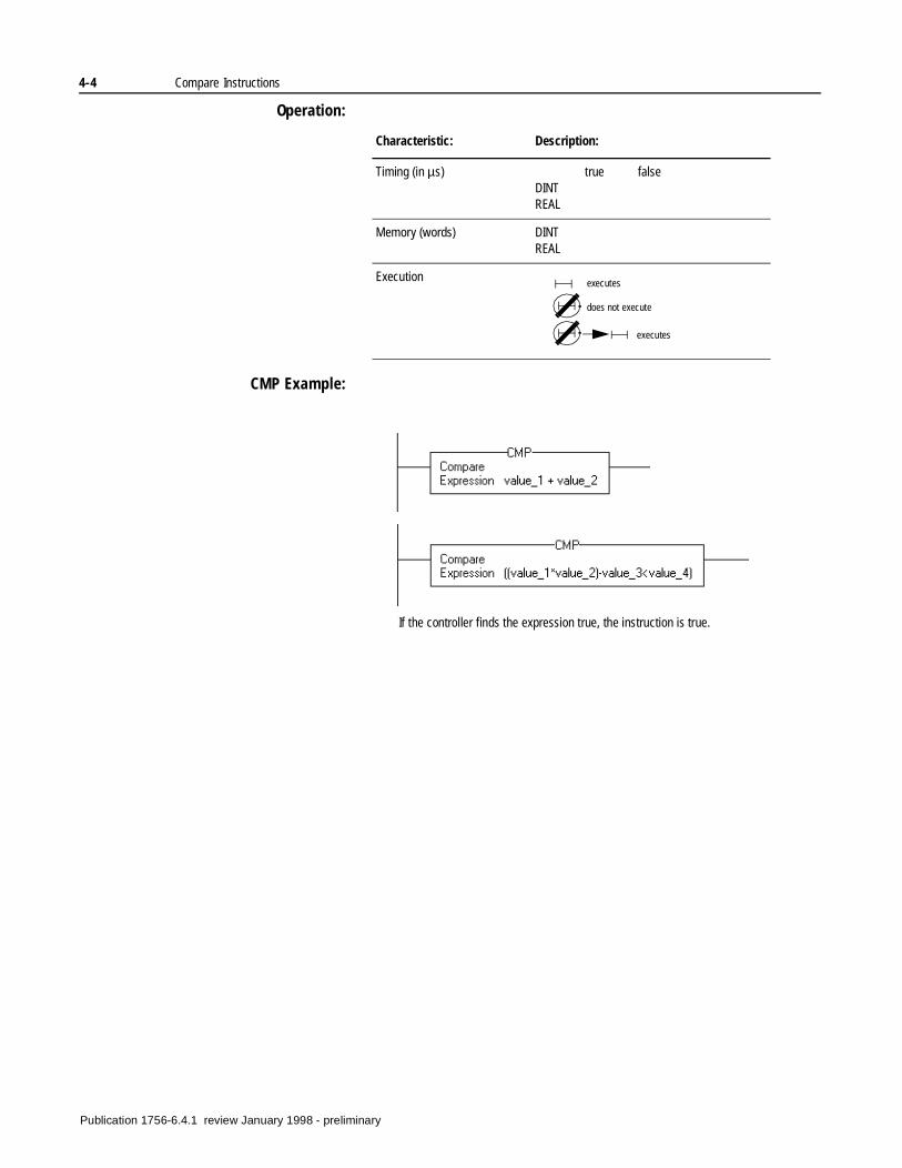
4-4 Compare Instructions
Operation:
CMP Example:
Characteristic: Description:
Timing (in µs) true falseDINTREAL
Memory (words) DINTREAL
Execution executes
does not execute
executes
If the controller finds the expression true, the instruction is true.
Publication 1756-6.4.1 review January 1998 - preliminary
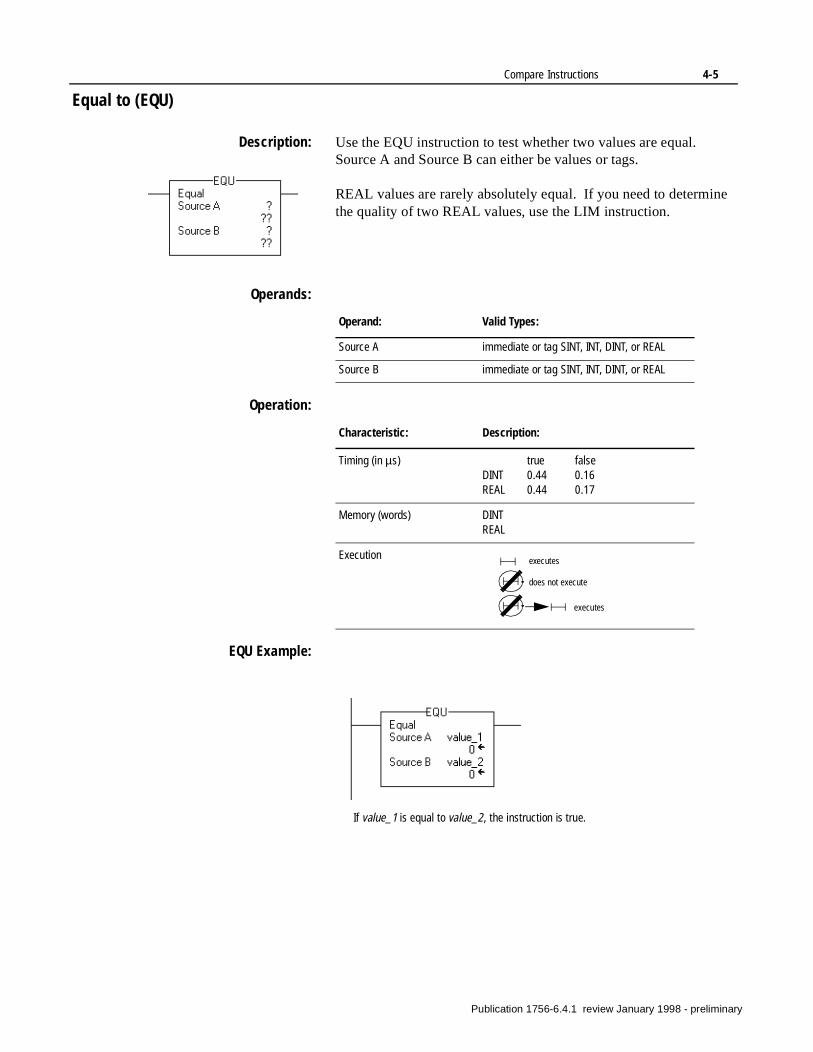
Compare Instructions 4-5
Equal to (EQU)
Description: Use the EQU instruction to test whether two values are equal. Source A and Source B can either be values or tags.
REAL values are rarely absolutely equal. If you need to determine the quality of two REAL values, use the LIM instruction.
Operands:
Operation:
EQU Example:
Operand: Valid Types:
Source A immediate or tag SINT, INT, DINT, or REAL
Source B immediate or tag SINT, INT, DINT, or REAL
Characteristic: Description:
Timing (in µs) true falseDINT 0.44 0.16REAL 0.44 0.17
Memory (words) DINTREAL
Execution executes
does not execute
executes
If value_1 is equal to value_2, the instruction is true.
Publication 1756-6.4.1 review January 1998 - preliminary
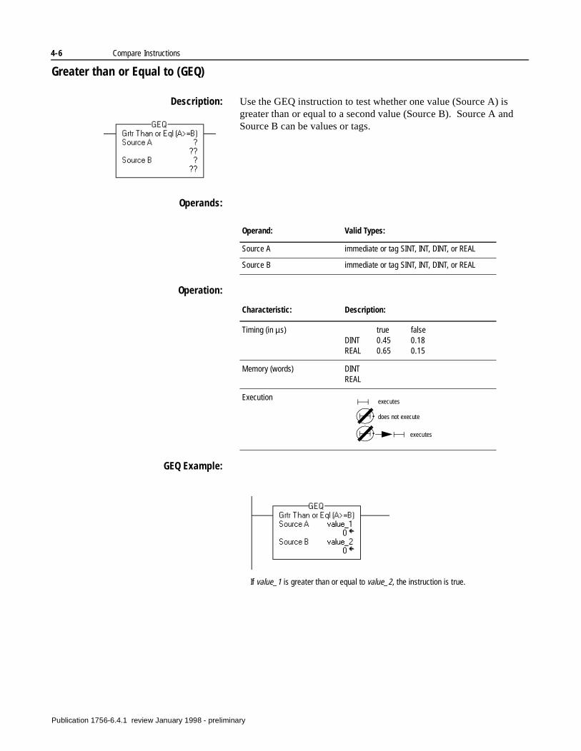
4-6 Compare Instructions
Greater than or Equal to (GEQ)
Description: Use the GEQ instruction to test whether one value (Source A) is greater than or equal to a second value (Source B). Source A and Source B can be values or tags.
Operands:
Operation:
GEQ Example:
Operand: Valid Types:
Source A immediate or tag SINT, INT, DINT, or REAL
Source B immediate or tag SINT, INT, DINT, or REAL
Characteristic: Description:
Timing (in µs) true falseDINT 0.45 0.18REAL 0.65 0.15
Memory (words) DINTREAL
Execution executes
does not execute
executes
If value_1 is greater than or equal to value_2, the instruction is true.
Publication 1756-6.4.1 review January 1998 - preliminary
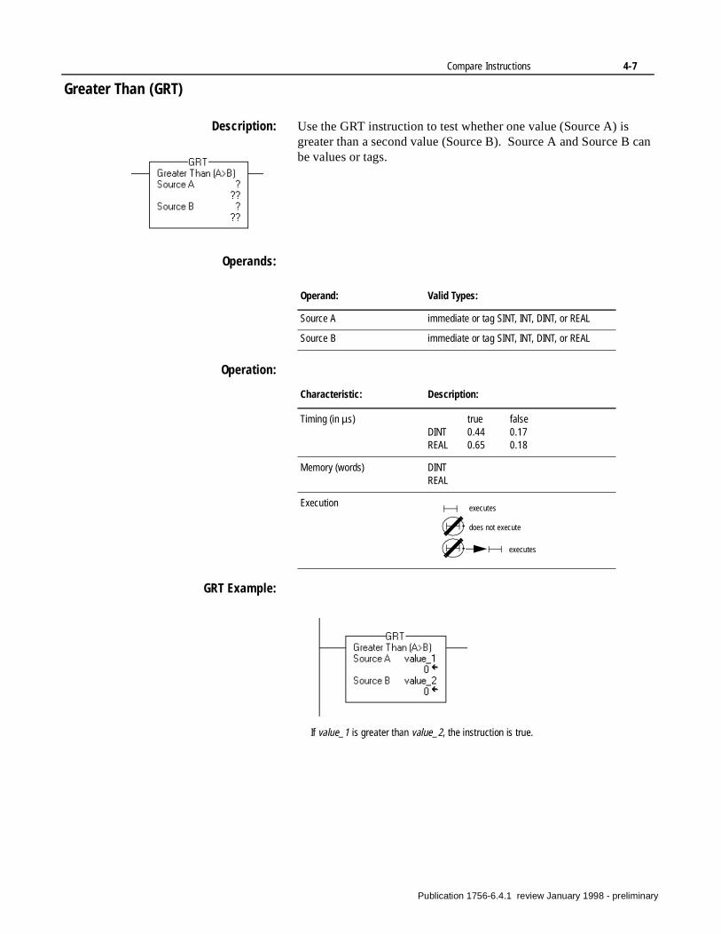
Compare Instructions 4-7
Greater Than (GRT)
Description: Use the GRT instruction to test whether one value (Source A) is greater than a second value (Source B). Source A and Source B can be values or tags.
Operands:
Operation:
GRT Example:
Operand: Valid Types:
Source A immediate or tag SINT, INT, DINT, or REAL
Source B immediate or tag SINT, INT, DINT, or REAL
Characteristic: Description:
Timing (in µs) true falseDINT 0.44 0.17REAL 0.65 0.18
Memory (words) DINTREAL
Execution executes
does not execute
executes
If value_1 is greater than value_2, the instruction is true.
Publication 1756-6.4.1 review January 1998 - preliminary

4-8 Compare Instructions
Less Than or Equal to (LEQ)
Description: Use the LEQ instruction to test whether one value (Source A) is less than or equal to a second value (Source B). Source A and Source B can be values or tags.
Operands:
Operation:
LEQ Example:
Operand: Valid Types:
Source A immediate or tag SINT, INT, DINT, or REAL
Source B immediate or tag SINT, INT, DINT, or REAL
Characteristic: Description:
Timing (in µs) true falseDINT 0.44 0.17REAL 0.65 0.18
Memory (words) DINTREAL
Execution executes
does not execute
executes
If value_1 is less than or equal to value_2, the instruction is true.
Publication 1756-6.4.1 review January 1998 - preliminary
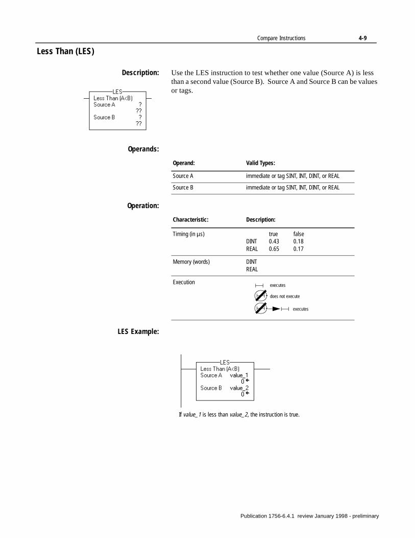
Compare Instructions 4-9
Less Than (LES)
Description: Use the LES instruction to test whether one value (Source A) is less than a second value (Source B). Source A and Source B can be values or tags.
Operands:
Operation:
LES Example:
Operand: Valid Types:
Source A immediate or tag SINT, INT, DINT, or REAL
Source B immediate or tag SINT, INT, DINT, or REAL
Characteristic: Description:
Timing (in µs) true falseDINT 0.43 0.18REAL 0.65 0.17
Memory (words) DINTREAL
Execution executes
does not execute
executes
If value_1 is less than value_2, the instruction is true.
Publication 1756-6.4.1 review January 1998 - preliminary
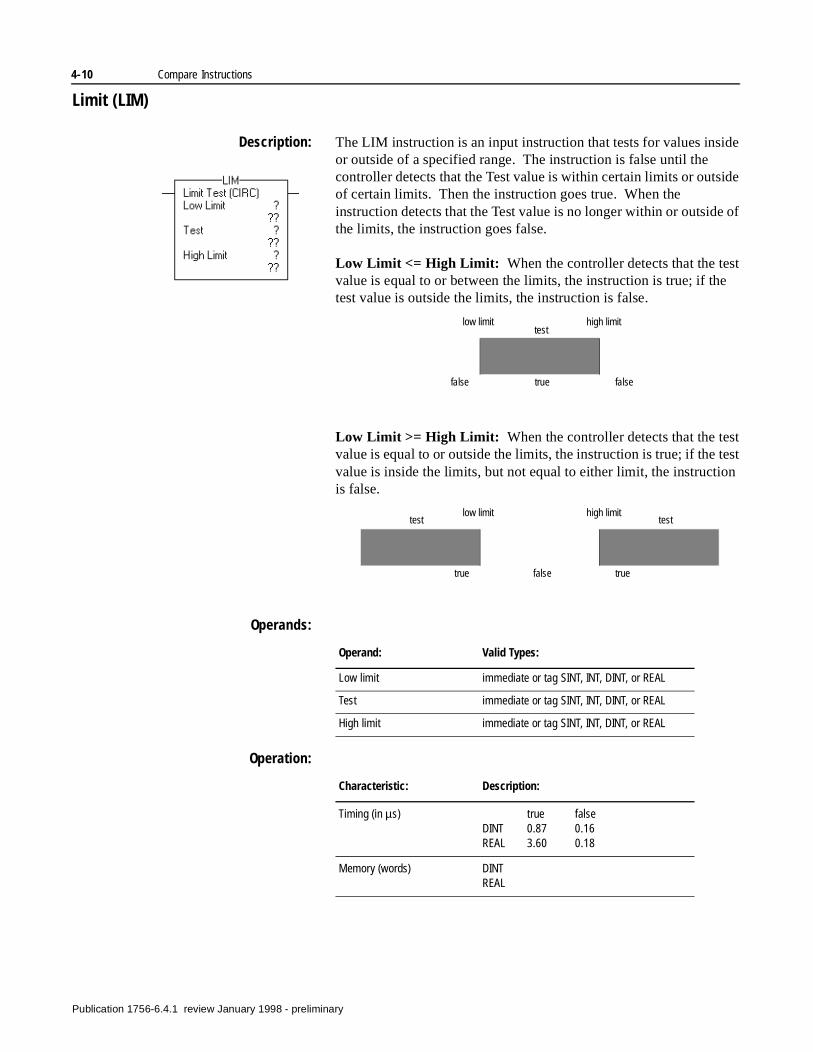
4-10 Compare Instructions
Limit (LIM)
Description: The LIM instruction is an input instruction that tests for values inside or outside of a specified range. The instruction is false until the controller detects that the Test value is within certain limits or outside of certain limits. Then the instruction goes true. When the instruction detects that the Test value is no longer within or outside of the limits, the instruction goes false.
Low Limit <= High Limit: When the controller detects that the test value is equal to or between the limits, the instruction is true; if the test value is outside the limits, the instruction is false.
Low Limit >= High Limit: When the controller detects that the test value is equal to or outside the limits, the instruction is true; if the test value is inside the limits, but not equal to either limit, the instruction is false.
Operands:
Operation:
low limit high limit
false true false
test
low limit high limit
true false true
test test
Operand: Valid Types:
Low limit immediate or tag SINT, INT, DINT, or REAL
Test immediate or tag SINT, INT, DINT, or REAL
High limit immediate or tag SINT, INT, DINT, or REAL
Characteristic: Description:
Timing (in µs) true falseDINT 0.87 0.16REAL 3.60 0.18
Memory (words) DINTREAL
Publication 1756-6.4.1 review January 1998 - preliminary
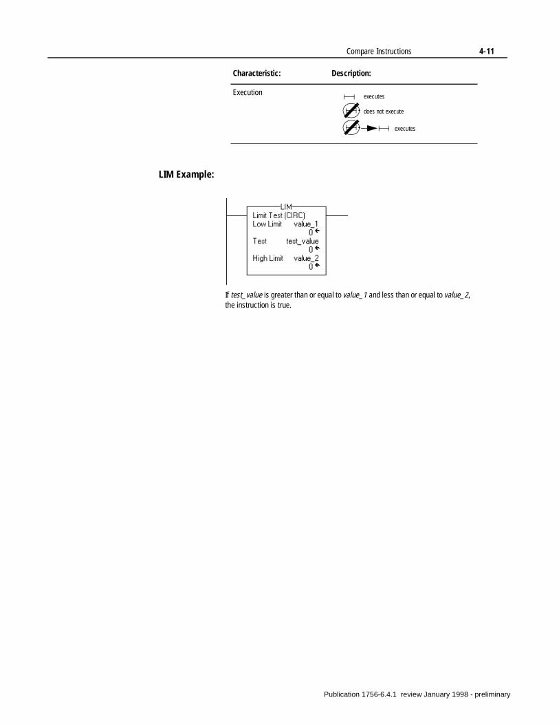
Compare Instructions 4-11
LIM Example:
Execution
Characteristic: Description:
executes
does not execute
executes
If test_value is greater than or equal to value_1 and less than or equal to value_2, the instruction is true.
Publication 1756-6.4.1 review January 1998 - preliminary
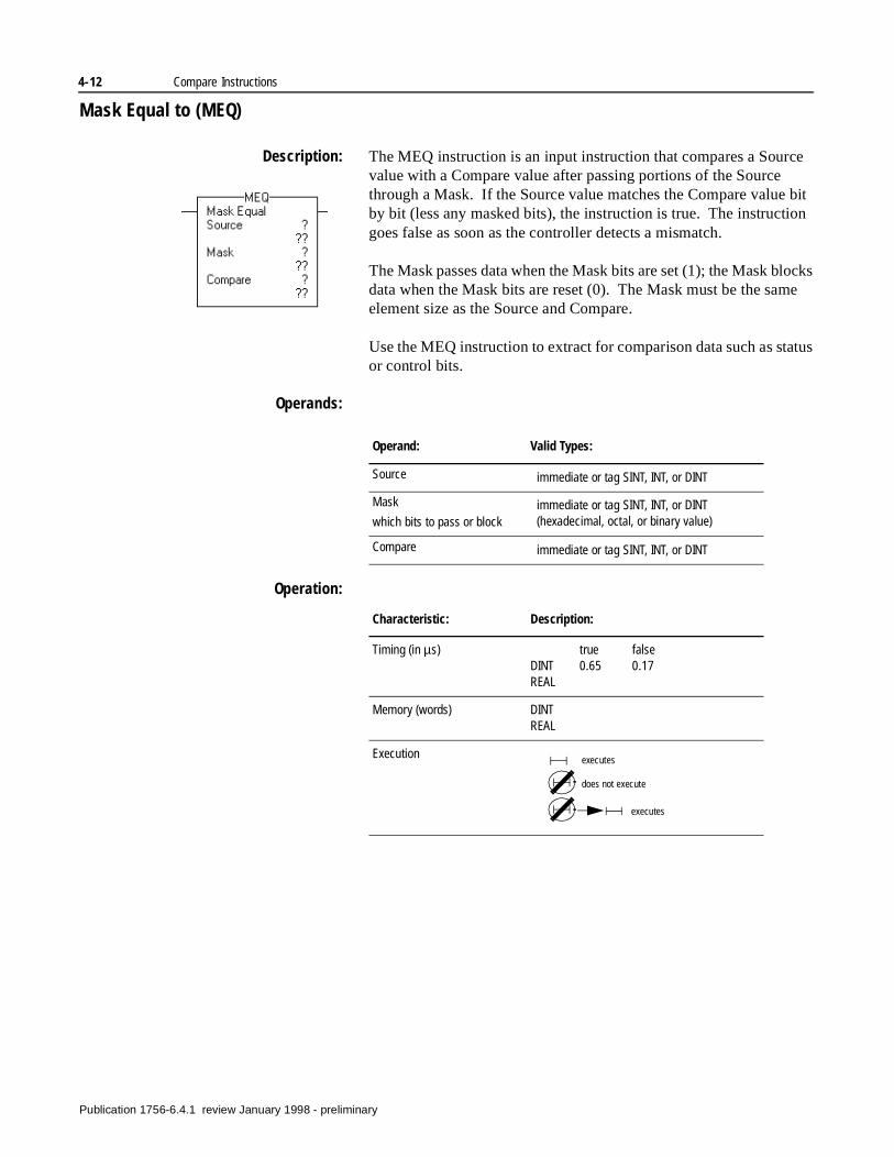
4-12 Compare Instructions
Mask Equal to (MEQ)
Description: The MEQ instruction is an input instruction that compares a Source value with a Compare value after passing portions of the Source through a Mask. If the Source value matches the Compare value bit by bit (less any masked bits), the instruction is true. The instruction goes false as soon as the controller detects a mismatch.
The Mask passes data when the Mask bits are set (1); the Mask blocks data when the Mask bits are reset (0). The Mask must be the same element size as the Source and Compare.
Use the MEQ instruction to extract for comparison data such as status or control bits.
Operands:
Operation:
Operand: Valid Types:
Source immediate or tag SINT, INT, or DINT
Mask
which bits to pass or blockimmediate or tag SINT, INT, or DINT (hexadecimal, octal, or binary value)
Compare immediate or tag SINT, INT, or DINT
Characteristic: Description:
Timing (in µs) true falseDINT 0.65 0.17REAL
Memory (words) DINTREAL
Execution executes
does not execute
executes
Publication 1756-6.4.1 review January 1998 - preliminary
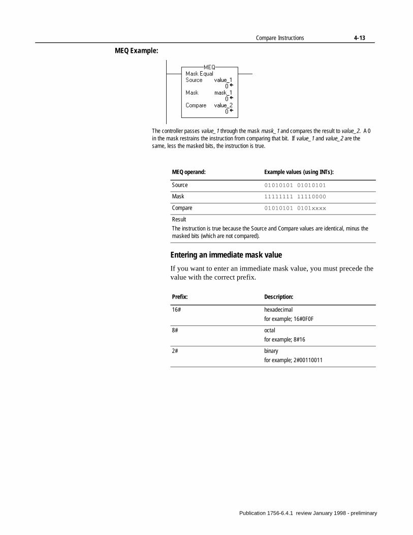
Compare Instructions 4-13
MEQ Example:
Entering an immediate mask value
If you want to enter an immediate mask value, you must precede the value with the correct prefix.
The controller passes value_1 through the mask mask_1 and compares the result to value_2. A 0 in the mask restrains the instruction from comparing that bit. If value_1 and value_2 are the same, less the masked bits, the instruction is true.
MEQ operand: Example values (using INTs):
Source 01010101 01010101
Mask 11111111 11110000
Compare 01010101 0101xxxx
Result
The instruction is true because the Source and Compare values are identical, minus the masked bits (which are not compared).
Prefix: Description:
16# hexadecimal
for example; 16#0F0F
8# octal
for example; 8#16
2# binary
for example; 2#00110011
Publication 1756-6.4.1 review January 1998 - preliminary
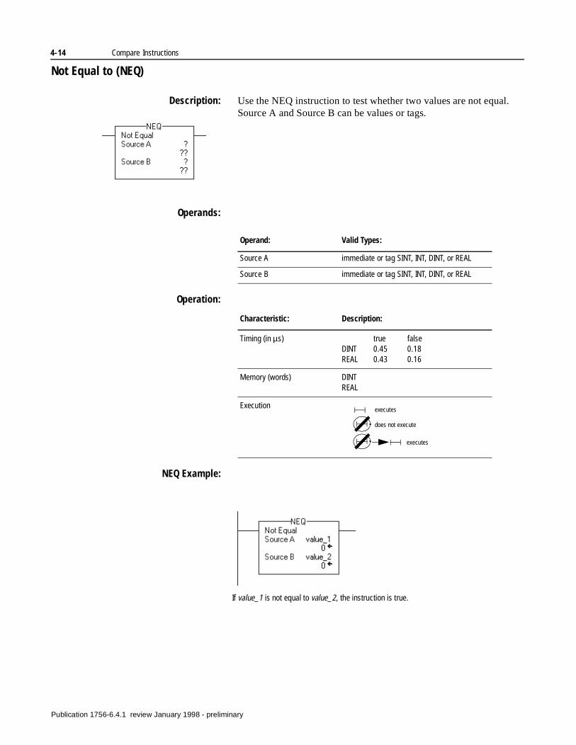
4-14 Compare Instructions
Not Equal to (NEQ)
Description: Use the NEQ instruction to test whether two values are not equal. Source A and Source B can be values or tags.
Operands:
Operation:
NEQ Example:
Operand: Valid Types:
Source A immediate or tag SINT, INT, DINT, or REAL
Source B immediate or tag SINT, INT, DINT, or REAL
Characteristic: Description:
Timing (in µs) true falseDINT 0.45 0.18REAL 0.43 0.16
Memory (words) DINTREAL
Execution executes
does not execute
executes
If value_1 is not equal to value_2, the instruction is true.
Publication 1756-6.4.1 review January 1998 - preliminary
Chapter 5
Compute/Math Instructions(CPT, ADD, SUB, MUL, DIV, SQR, NEG)
Introduction The compute/math instructions evaluate arithmetic operations using an expression or a specific arithmetic instruction.
You can mix values of different data types, such as floating point and integer. If you use floating point as the source, use floating point as the destination. You can mix data types, but loss of accuracy and rounding error might occur.
If the rung with the compute instruction goes true, the controller performs the computation.
Using arithmetic status flags
To access arithmetic status flags, use an XIC or XIO instruction with one of the status keywords.
Use the RES instruction to clear the status flags.
If you want to: Use this instruction: See page:
evaluate an expression CPT 5-2
add two values ADD 5-4
subtract two values SUB 5-5
multiply two values MUL 5-6
divide two values DIV 5-7
take the square root of a value SQR 5-8
take the opposite sign of a value NEG 5-9
Use this keyword: For this status flag: With this read/write access:
S:C carry read/write
S:N sign (result is negative) read/write
S: V overflow read/write
S:Z zero read/write
Publication 1756-6.4.1 review January 1998 - preliminary
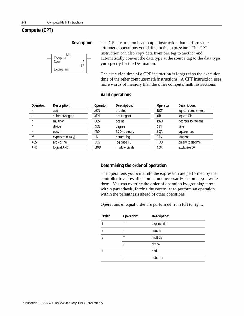
5-2 Compute/Math Instructions
Compute (CPT)
Description: The CPT instruction is an output instruction that performs the arithmetic operations you define in the expression. The CPT instruction can also copy data from one tag to another and automatically convert the data type at the source tag to the data type you specify for the Destination.
The execution time of a CPT instruction is longer than the execution time of the other compute/math instructions. A CPT instruction uses more words of memory than the other compute/math instructions.
Valid operations
Determining the order of operation
The operations you write into the expression are performed by the controller in a prescribed order, not necessarily the order you write them. You can override the order of operation by grouping terms within parenthesis, forcing the controller to perform an operation within the parenthesis ahead of other operations.
Operations of equal order are performed from left to right.
Operator: Description:
+ add
- subtract/negate
* multiply
/ divide
= equal
** exponent (x to y)
ACS arc cosine
AND logical AND
ASN arc sine
ATN arc tangent
COS cosine
DEG degree
FRD BCD to binary
LN natural log
LOG log base 10
MOD modulo divide
Operator: Description:
NOT logical complement
OR logical OR
RAD degrees to radians
SIN sine
SQR square root
TAN tangent
TOD binary to decimal
XOR exclusive OR
Operator: Description:
Order: Operation: Description:
1 ** exponential
2 - negate
3 * multiply
/ divide
4 + add
- subtract
Pu
blication 1756-6.4.1 review January 1998 - preliminary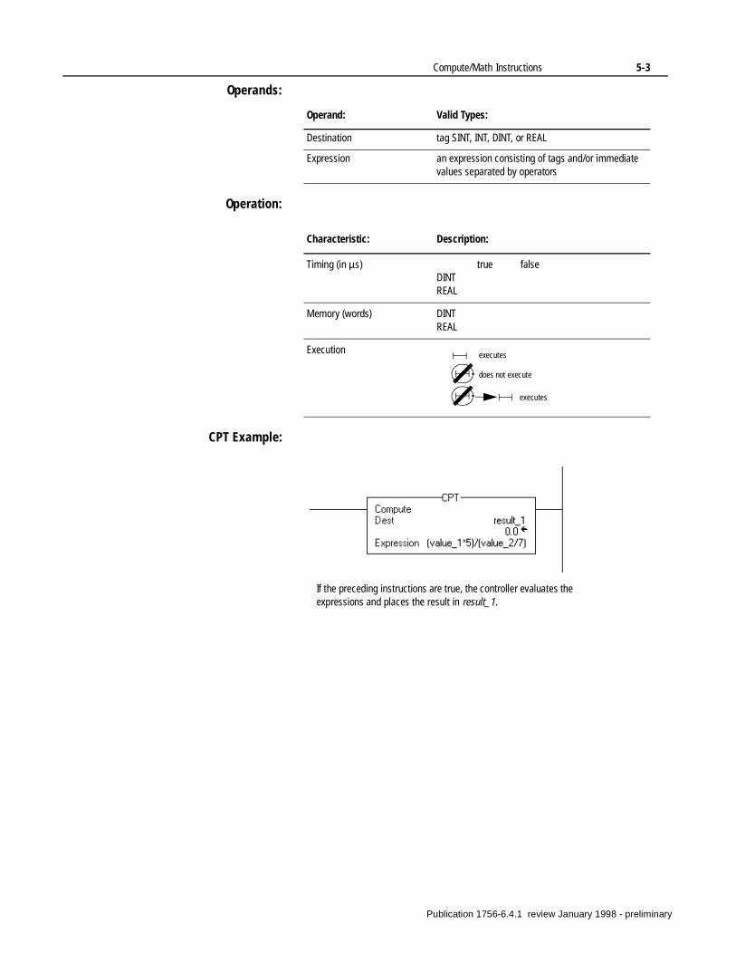
Compute/Math Instructions 5-3
Operands:
Operation:
CPT Example:
Operand: Valid Types:
Destination tag SINT, INT, DINT, or REAL
Expression an expression consisting of tags and/or immediate values separated by operators
Characteristic: Description:
Timing (in µs) true falseDINTREAL
Memory (words) DINTREAL
Execution executes
does not execute
executes
If the preceding instructions are true, the controller evaluates the expressions and places the result in result_1.
Publication 1756-6.4.1 review January 1998 - preliminary
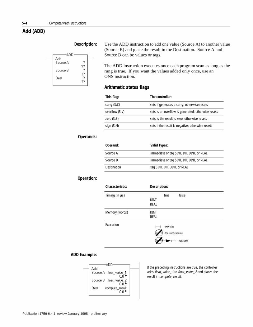
5-4 Compute/Math Instructions
Add (ADD)
Description: Use the ADD instruction to add one value (Source A) to another value (Source B) and place the result in the Destination. Source A and Source B can be values or tags.
The ADD instruction executes once each program scan as long as the rung is true. If you want the values added only once, use an ONS instruction.
Arithmetic status flags
Operands:
Operation:
ADD Example:
This flag: The controller:
carry (S:C) sets if generates a carry; otherwise resets
overflow (S:V) sets is an overflow is generated; otherwise resets
zero (S:Z) sets is the result is zero; otherwise resets
sign (S:N) sets if the result is negative; otherwise resets
Operand: Valid Types:
Source A immediate or tag SINT, INT, DINT, or REAL
Source B immediate or tag SINT, INT, DINT, or REAL
Destination tag SINT, INT, DINT, or REAL
Characteristic: Description:
Timing (in µs) true falseDINTREAL
Memory (words) DINTREAL
Execution executes
does not execute
executes
If the preceding instructions are true, the controller adds float_value_1 to float_value_2 and places the result in compute_result.
Publication 1756-6.4.1 review January 1998 - preliminary
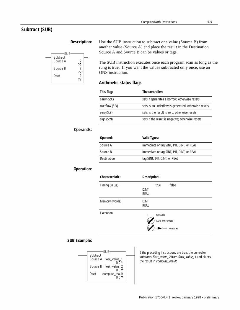
Compute/Math Instructions 5-5
Subtract (SUB)
Description: Use the SUB instruction to subtract one value (Source B) from another value (Source A) and place the result in the Destination. Source A and Source B can be values or tags.
The SUB instruction executes once each program scan as long as the rung is true. If you want the values subtracted only once, use an ONS instruction.
Arithmetic status flags
Operands:
Operation:
SUB Example:
This flag: The controller:
carry (S:C) sets if generates a borrow; otherwise resets
overflow (S:V) sets is an underflow is generated; otherwise resets
zero (S:Z) sets is the result is zero; otherwise resets
sign (S:N) sets if the result is negative; otherwise resets
Operand: Valid Types:
Source A immediate or tag SINT, INT, DINT, or REAL
Source B immediate or tag SINT, INT, DINT, or REAL
Destination tag SINT, INT, DINT, or REAL
Characteristic: Description:
Timing (in µs) true falseDINTREAL
Memory (words) DINTREAL
Execution executes
does not execute
executes
If the preceding instructions are true, the controller subtracts float_value_2 from float_value_1 and places the result in compute_result.
Publication 1756-6.4.1 review January 1998 - preliminary
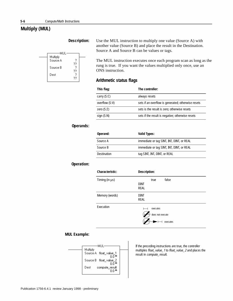
5-6 Compute/Math Instructions
Multiply (MUL)
Description: Use the MUL instruction to multiply one value (Source A) with another value (Source B) and place the result in the Destination. Source A and Source B can be values or tags.
The MUL instruction executes once each program scan as long as the rung is true. If you want the values multiplied only once, use an ONS instruction.
Arithmetic status flags
Operands:
Operation:
MUL Example:
This flag: The controller:
carry (S:C) always resets
overflow (S:V) sets if an overflow is generated; otherwise resets
zero (S:Z) sets is the result is zero; otherwise resets
sign (S:N) sets if the result is negative; otherwise resets
Operand: Valid Types:
Source A immediate or tag SINT, INT, DINT, or REAL
Source B immediate or tag SINT, INT, DINT, or REAL
Destination tag SINT, INT, DINT, or REAL
Characteristic: Description:
Timing (in µs) true falseDINTREAL
Memory (words) DINTREAL
Execution executes
does not execute
executes
If the preceding instructions are true, the controller multiples float_value_1 to float_value_2 and places the result in compute_result.
Publication 1756-6.4.1 review January 1998 - preliminary
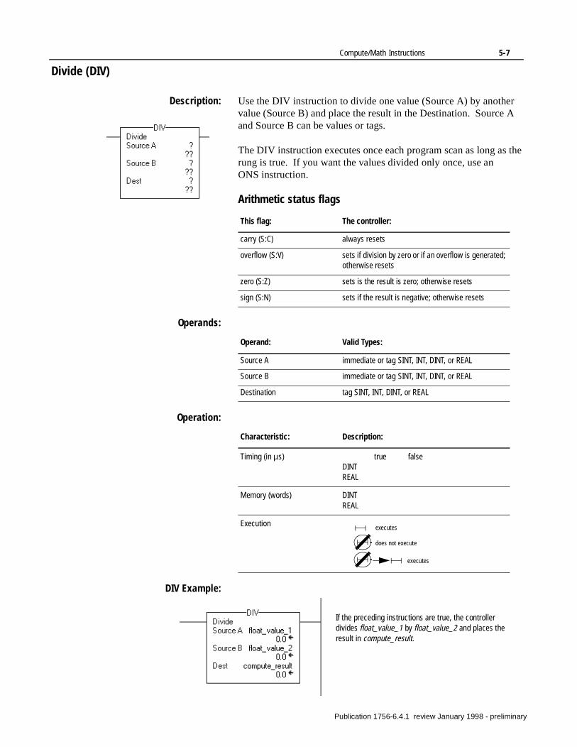
Compute/Math Instructions 5-7
Divide (DIV)
Description: Use the DIV instruction to divide one value (Source A) by another value (Source B) and place the result in the Destination. Source A and Source B can be values or tags.
The DIV instruction executes once each program scan as long as the rung is true. If you want the values divided only once, use an ONS instruction.
Arithmetic status flags
Operands:
Operation:
DIV Example:
This flag: The controller:
carry (S:C) always resets
overflow (S:V) sets if division by zero or if an overflow is generated; otherwise resets
zero (S:Z) sets is the result is zero; otherwise resets
sign (S:N) sets if the result is negative; otherwise resets
Operand: Valid Types:
Source A immediate or tag SINT, INT, DINT, or REAL
Source B immediate or tag SINT, INT, DINT, or REAL
Destination tag SINT, INT, DINT, or REAL
Characteristic: Description:
Timing (in µs) true falseDINTREAL
Memory (words) DINTREAL
Execution executes
does not execute
executes
If the preceding instructions are true, the controller divides float_value_1 by float_value_2 and places the result in compute_result.
Publication 1756-6.4.1 review January 1998 - preliminary
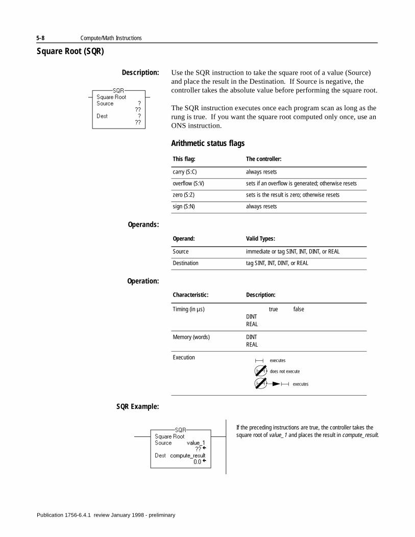
5-8 Compute/Math Instructions
Square Root (SQR)
Description: Use the SQR instruction to take the square root of a value (Source) and place the result in the Destination. If Source is negative, the controller takes the absolute value before performing the square root.
The SQR instruction executes once each program scan as long as the rung is true. If you want the square root computed only once, use an ONS instruction.
Arithmetic status flags
Operands:
Operation:
SQR Example:
This flag: The controller:
carry (S:C) always resets
overflow (S:V) sets if an overflow is generated; otherwise resets
zero (S:Z) sets is the result is zero; otherwise resets
sign (S:N) always resets
Operand: Valid Types:
Source immediate or tag SINT, INT, DINT, or REAL
Destination tag SINT, INT, DINT, or REAL
Characteristic: Description:
Timing (in µs) true falseDINTREAL
Memory (words) DINTREAL
Execution executes
does not execute
executes
If the preceding instructions are true, the controller takes the square root of value_1 and places the result in compute_result.
Publication 1756-6.4.1 review January 1998 - preliminary
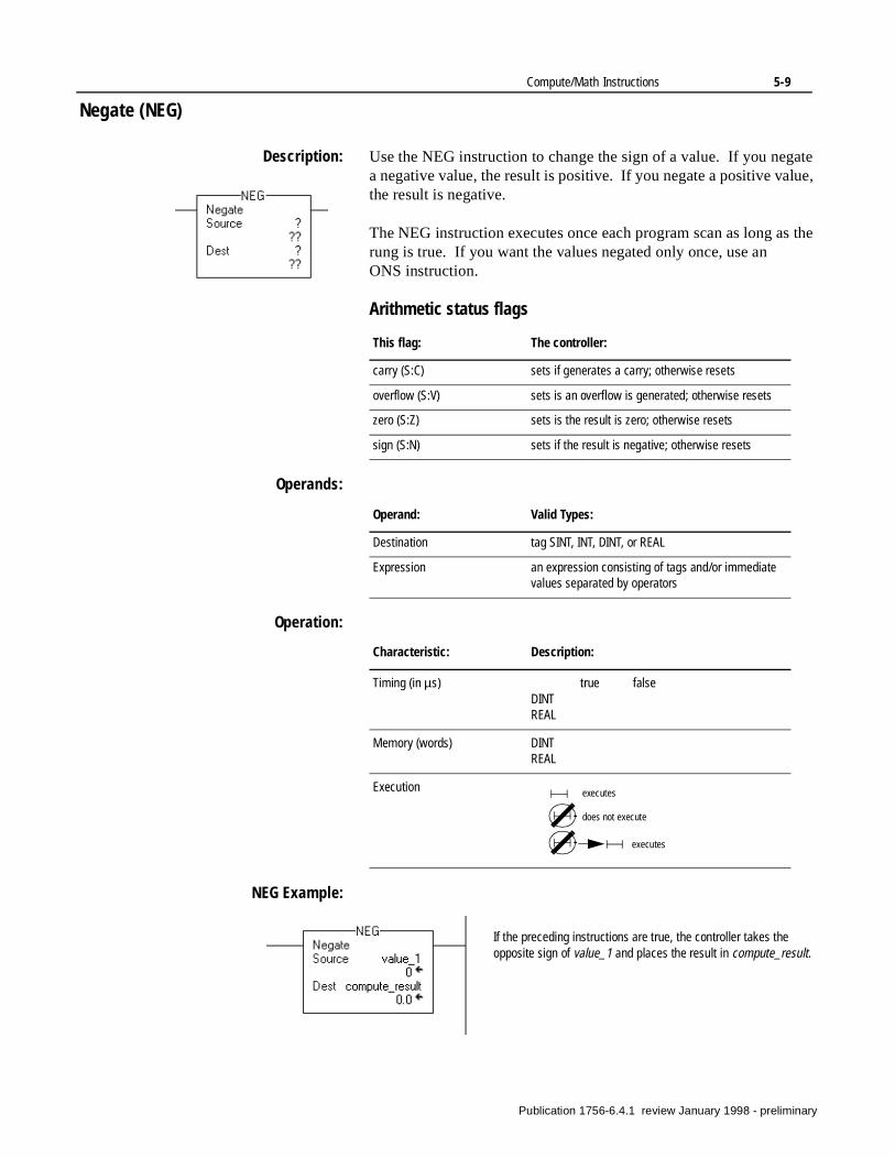
Compute/Math Instructions 5-9
Negate (NEG)
Description: Use the NEG instruction to change the sign of a value. If you negate a negative value, the result is positive. If you negate a positive value, the result is negative.
The NEG instruction executes once each program scan as long as the rung is true. If you want the values negated only once, use an ONS instruction.
Arithmetic status flags
Operands:
Operation:
NEG Example:
This flag: The controller:
carry (S:C) sets if generates a carry; otherwise resets
overflow (S:V) sets is an overflow is generated; otherwise resets
zero (S:Z) sets is the result is zero; otherwise resets
sign (S:N) sets if the result is negative; otherwise resets
Operand: Valid Types:
Destination tag SINT, INT, DINT, or REAL
Expression an expression consisting of tags and/or immediate values separated by operators
Characteristic: Description:
Timing (in µs) true falseDINTREAL
Memory (words) DINTREAL
Execution executes
does not execute
executes
If the preceding instructions are true, the controller takes the opposite sign of value_1 and places the result in compute_result.
Publication 1756-6.4.1 review January 1998 - preliminary

5-10 Compute/Math Instructions
Notes:
Publication 1756-6.4.1 review January 1998 - preliminary
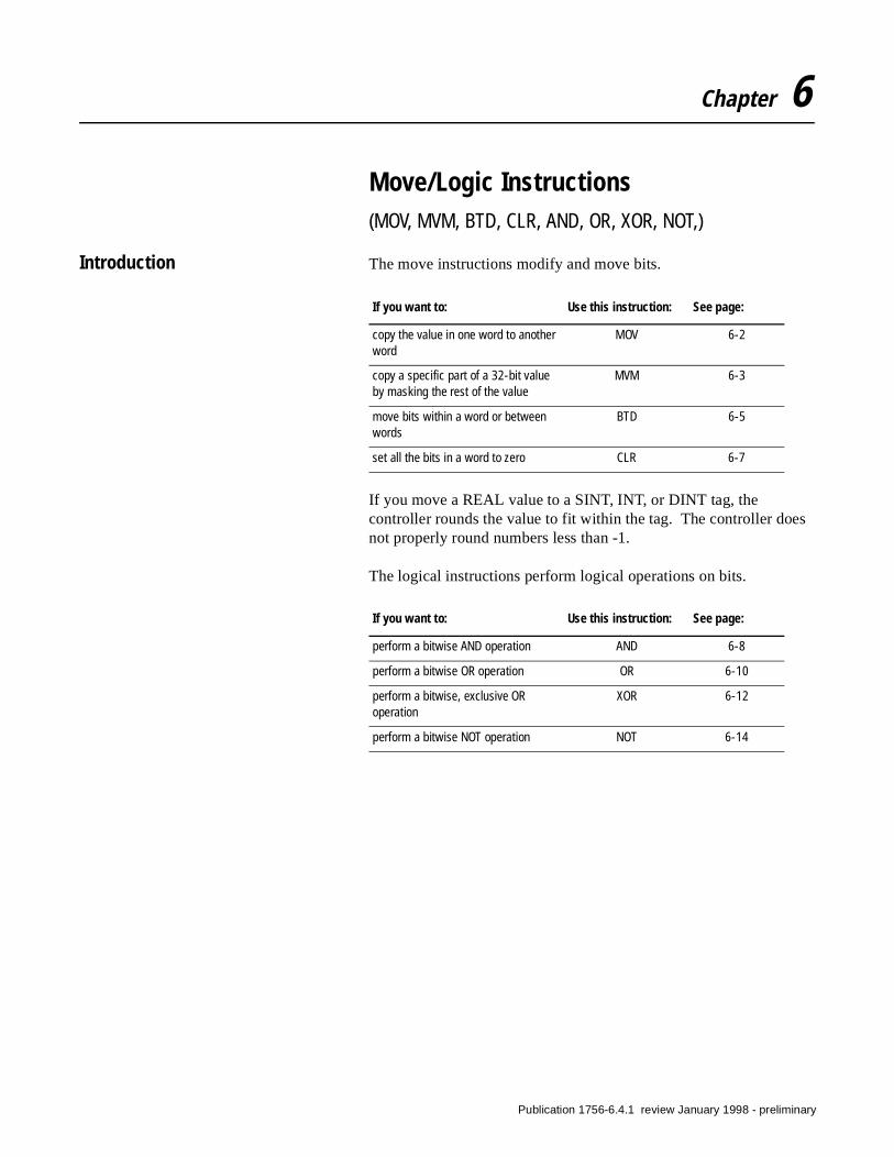
Chapter 6
Move/Logic Instructions(MOV, MVM, BTD, CLR, AND, OR, XOR, NOT,)
Introduction The move instructions modify and move bits.
If you move a REAL value to a SINT, INT, or DINT tag, the controller rounds the value to fit within the tag. The controller does not properly round numbers less than -1.
The logical instructions perform logical operations on bits.
If you want to: Use this instruction: See page:
copy the value in one word to another word
MOV 6-2
copy a specific part of a 32-bit value by masking the rest of the value
MVM 6-3
move bits within a word or between words
BTD 6-5
set all the bits in a word to zero CLR 6-7
If you want to: Use this instruction: See page:
perform a bitwise AND operation AND 6-8
perform a bitwise OR operation OR 6-10
perform a bitwise, exclusive OR operation
XOR 6-12
perform a bitwise NOT operation NOT 6-14
Publication 1756-6.4.1 review January 1998 - preliminary
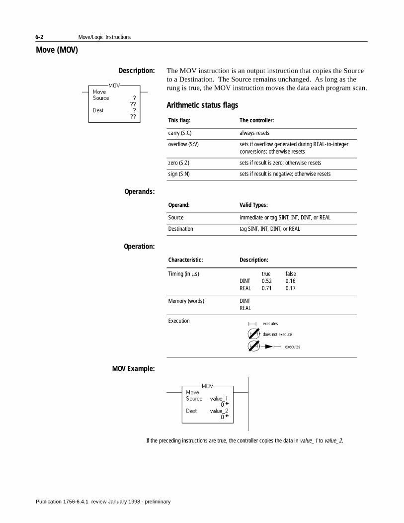
6-2 Move/Logic Instructions
Move (MOV)
Description: The MOV instruction is an output instruction that copies the Source to a Destination. The Source remains unchanged. As long as the rung is true, the MOV instruction moves the data each program scan.
Arithmetic status flags
Operands:
Operation:
MOV Example:
This flag: The controller:
carry (S:C) always resets
overflow (S:V) sets if overflow generated during REAL-to-integer conversions; otherwise resets
zero (S:Z) sets if result is zero; otherwise resets
sign (S:N) sets if result is negative; otherwise resets
Operand: Valid Types:
Source immediate or tag SINT, INT, DINT, or REAL
Destination tag SINT, INT, DINT, or REAL
Characteristic: Description:
Timing (in µs) true falseDINT 0.52 0.16REAL 0.71 0.17
Memory (words) DINTREAL
Execution executes
does not execute
executes
If the preceding instructions are true, the controller copies the data in value_1 to value_2.
Publication 1756-6.4.1 review January 1998 - preliminary
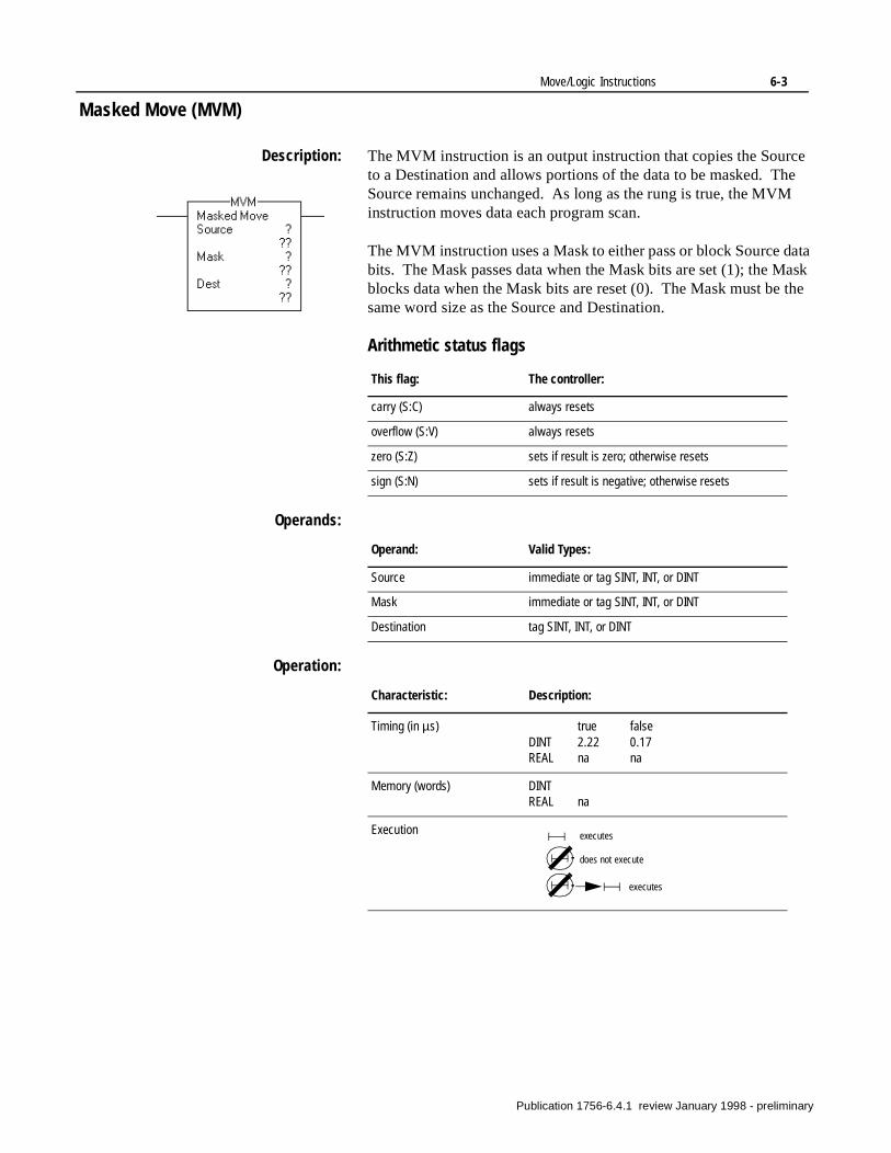
Move/Logic Instructions 6-3
Masked Move (MVM)
Description: The MVM instruction is an output instruction that copies the Source to a Destination and allows portions of the data to be masked. The Source remains unchanged. As long as the rung is true, the MVM instruction moves data each program scan.
The MVM instruction uses a Mask to either pass or block Source data bits. The Mask passes data when the Mask bits are set (1); the Mask blocks data when the Mask bits are reset (0). The Mask must be the same word size as the Source and Destination.
Arithmetic status flags
Operands:
Operation:
This flag: The controller:
carry (S:C) always resets
overflow (S:V) always resets
zero (S:Z) sets if result is zero; otherwise resets
sign (S:N) sets if result is negative; otherwise resets
Operand: Valid Types:
Source immediate or tag SINT, INT, or DINT
Mask immediate or tag SINT, INT, or DINT
Destination tag SINT, INT, or DINT
Characteristic: Description:
Timing (in µs) true falseDINT 2.22 0.17REAL na na
Memory (words) DINTREAL na
Execution executes
does not execute
executes
Publication 1756-6.4.1 review January 1998 - preliminary
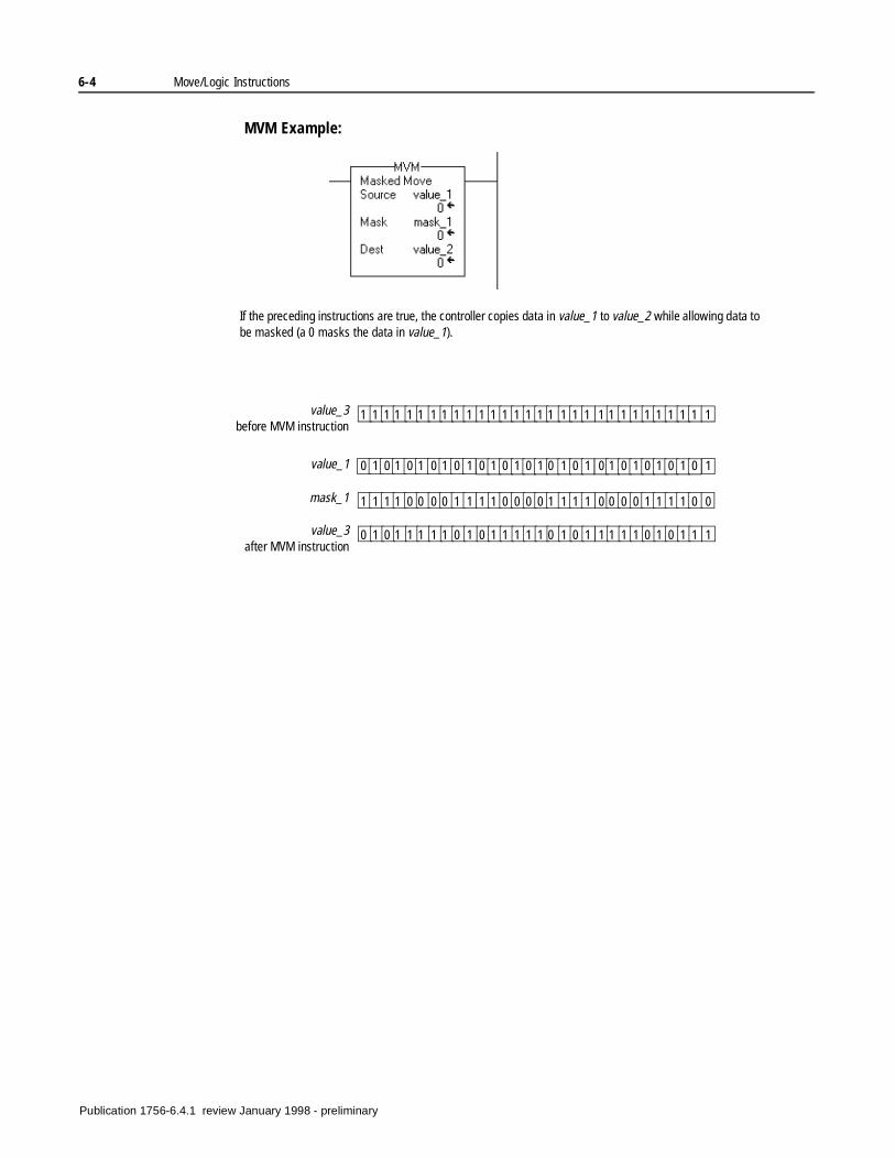
6-4 Move/Logic Instructions
MVM Example:
If the preceding instructions are true, the controller copies data in value_1 to value_2 while allowing data to be masked (a 0 masks the data in value_1).
0 1 0 1 0 1 0 1 0 1 0 1 0 1 0 1 0 1 0 1 0 1 0 1 0 1 0 1 0 1
1 1 1 1 0 0 0 0 1 1 1 1 0 0 0 0 1 1 1 1 0 0 0 0 1 1 1 1 0 0
0 1 0 1 1 1 1 1 0 1 0 1 1 1 1 1 0 1 0 1 1 1 1 1 0 1 0 1 1 1
value_1
mask_1
value_3after MVM instruction
1 1 1 1 1 1 1 1 1 1 1 1 1 1 1 1 1 1 1 1 1 1 1 1 1 1 1 1 1 1value_3before MVM instruction
Publication 1756-6.4.1 review January 1998 - preliminary
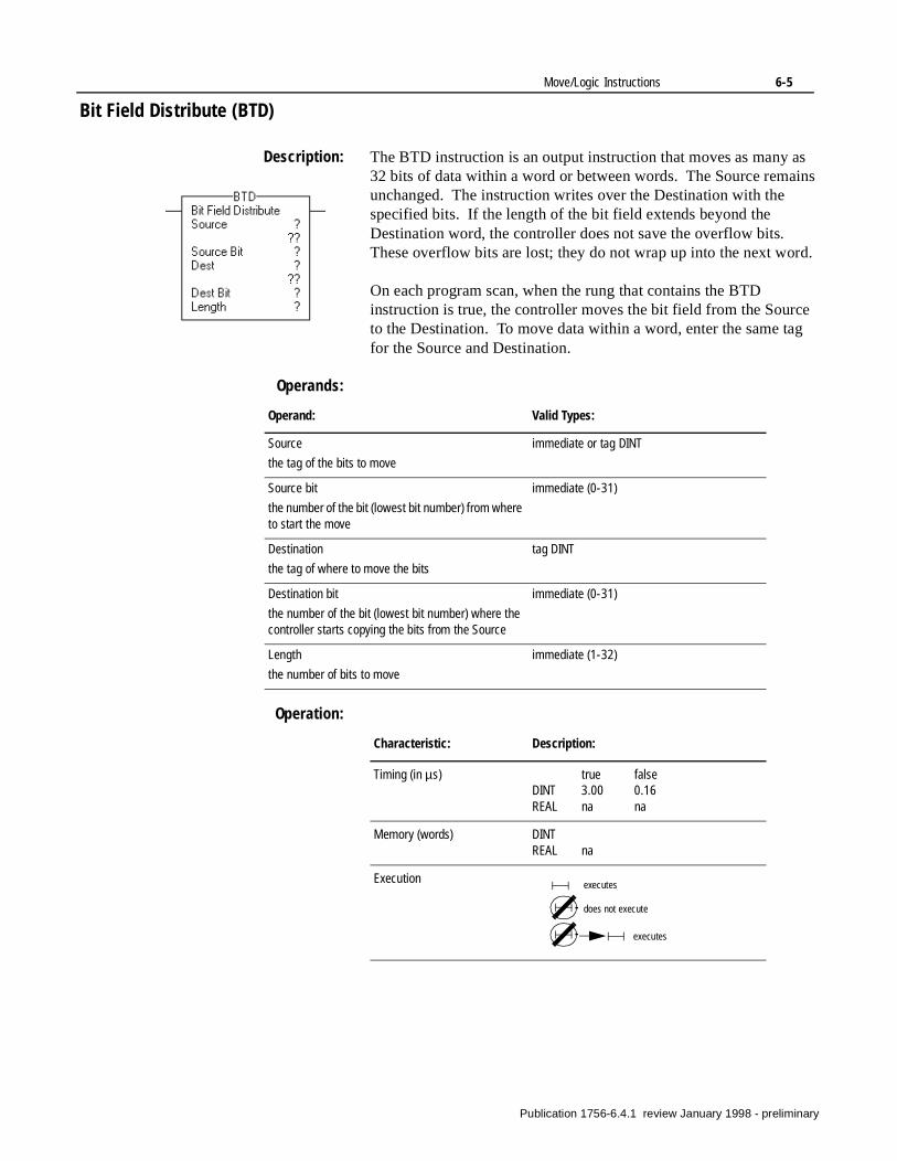
Move/Logic Instructions 6-5
Bit Field Distribute (BTD)
Description: The BTD instruction is an output instruction that moves as many as 32 bits of data within a word or between words. The Source remains unchanged. The instruction writes over the Destination with the specified bits. If the length of the bit field extends beyond the Destination word, the controller does not save the overflow bits. These overflow bits are lost; they do not wrap up into the next word.
On each program scan, when the rung that contains the BTD instruction is true, the controller moves the bit field from the Source to the Destination. To move data within a word, enter the same tag for the Source and Destination.
Operands:
Operation:
Operand: Valid Types:
Source
the tag of the bits to move
immediate or tag DINT
Source bit
the number of the bit (lowest bit number) from where to start the move
immediate (0-31)
Destination
the tag of where to move the bits
tag DINT
Destination bit
the number of the bit (lowest bit number) where the controller starts copying the bits from the Source
immediate (0-31)
Length
the number of bits to move
immediate (1-32)
Characteristic: Description:
Timing (in µs) true falseDINT 3.00 0.16REAL na na
Memory (words) DINTREAL na
Execution executes
does not execute
executes
Publication 1756-6.4.1 review January 1998 - preliminary
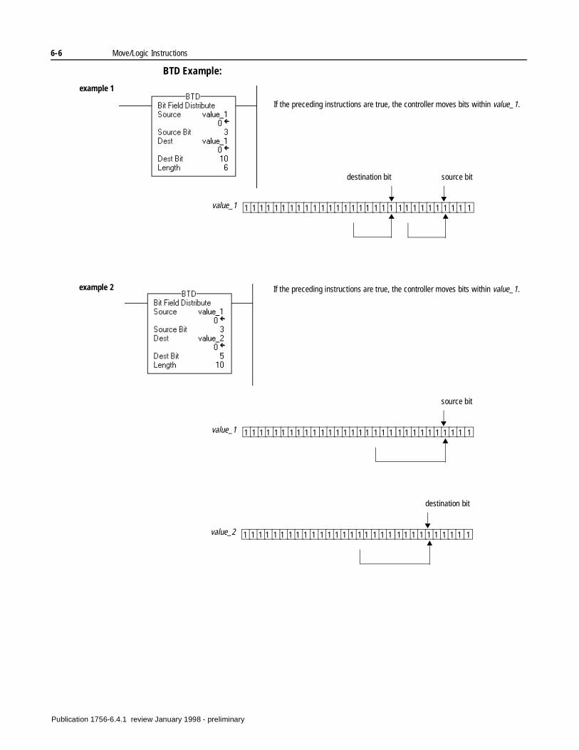
6-6 Move/Logic Instructions
BTD Example:
If the preceding instructions are true, the controller moves bits within value_1.
1 1 1 1 1 1 1 1 1 1 1 1 1 1 1 1 1 1 1 1 1 1 1 1 1 1 1 1 1 1value_1
source bitdestination bit
If the preceding instructions are true, the controller moves bits within value_1.
example 1
example 2
1 1 1 1 1 1 1 1 1 1 1 1 1 1 1 1 1 1 1 1 1 1 1 1 1 1 1 1 1 1value_1
source bit
1 1 1 1 1 1 1 1 1 1 1 1 1 1 1 1 1 1 1 1 1 1 1 1 1 1 1 1 1 1value_2
destination bit
Publication 1756-6.4.1 review January 1998 - preliminary
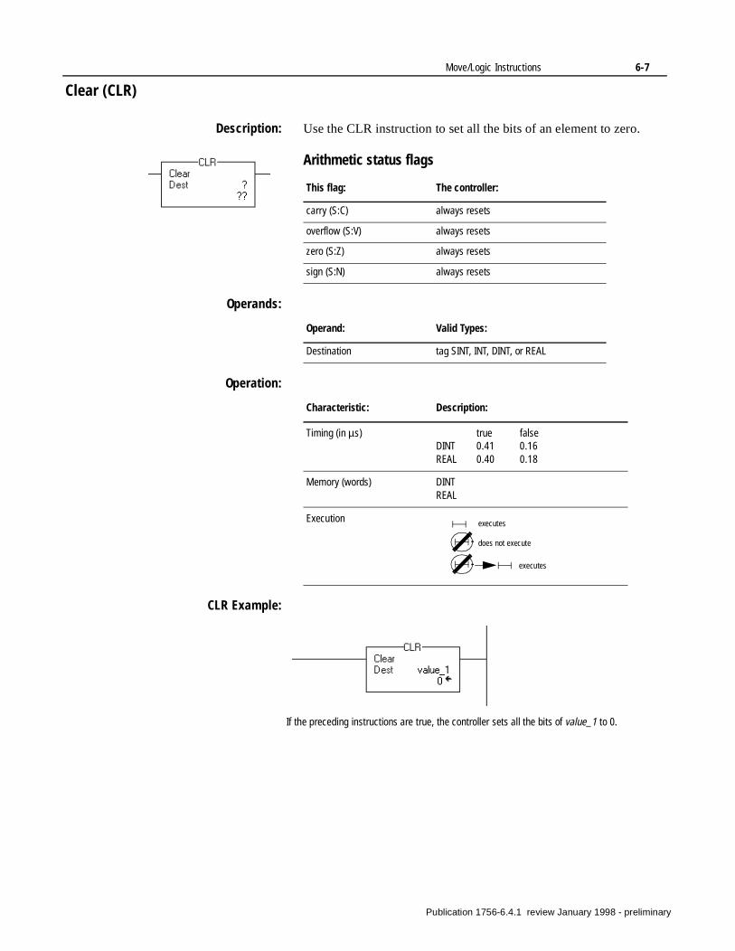
Move/Logic Instructions 6-7
Clear (CLR)
Description: Use the CLR instruction to set all the bits of an element to zero.
Arithmetic status flags
Operands:
Operation:
CLR Example:
This flag: The controller:
carry (S:C) always resets
overflow (S:V) always resets
zero (S:Z) always resets
sign (S:N) always resets
Operand: Valid Types:
Destination tag SINT, INT, DINT, or REAL
Characteristic: Description:
Timing (in µs) true falseDINT 0.41 0.16REAL 0.40 0.18
Memory (words) DINTREAL
Execution executes
does not execute
executes
If the preceding instructions are true, the controller sets all the bits of value_1 to 0.
Publication 1756-6.4.1 review January 1998 - preliminary
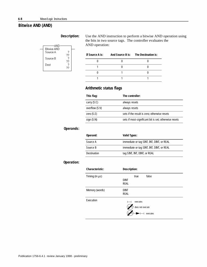
6-8 Move/Logic Instructions
Bitwise AND (AND)
Description: Use the AND instruction to perform a bitwise AND operation using the bits in two source tags. The controller evaluates the AND operation:
Arithmetic status flags
Operands:
Operation:
If Source A is: And Source B is: The Destination is:
0 0 0
1 0 0
0 1 0
1 1 1
This flag: The controller:
carry (S:C) always resets
overflow (S:V) always resets
zero (S:Z) sets if the result is zero; otherwise resets
sign (S:N) sets if most-significant bit is set; otherwise resets
Operand: Valid Types:
Source A immediate or tag SINT, INT, DINT, or REAL
Source B immediate or tag SINT, INT, DINT, or REAL
Destination tag SINT, INT, DINT, or REAL
Characteristic: Description:
Timing (in µs) true falseDINTREAL
Memory (words) DINTREAL
Execution executes
does not execute
executes
Publication 1756-6.4.1 review January 1998 - preliminary
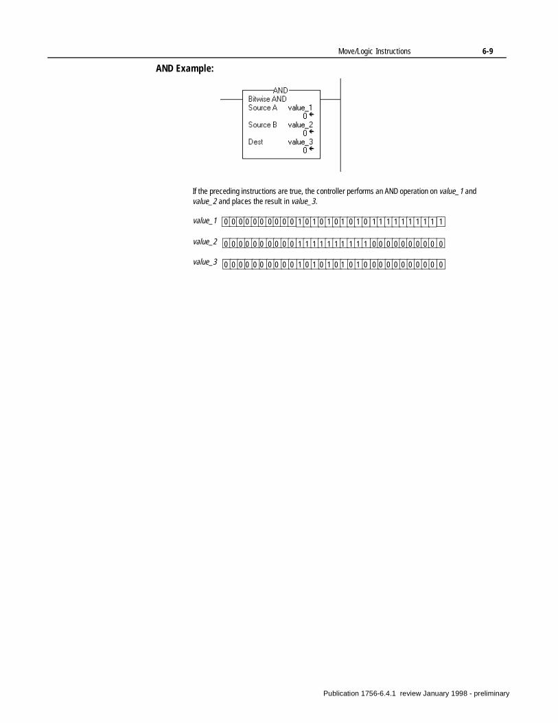
Move/Logic Instructions 6-9
AND Example:
If the preceding instructions are true, the controller performs an AND operation on value_1 and value_2 and places the result in value_3.
0 0 0 0 0 0 0 0 0 0 1 0 1 0 1 0 1 0 1 0 1 1 1 1 1 1 1 1 1 1
0 0 0 0 0 0 0 0 0 0 1 1 1 1 1 1 1 1 1 1 0 0 0 0 0 0 0 0 0 0
0 0 0 0 0 0 0 0 0 0 1 0 1 0 1 0 1 0 1 0 0 0 0 0 0 0 0 0 0 0
value_1
value_2
value_3
Publication 1756-6.4.1 review January 1998 - preliminary
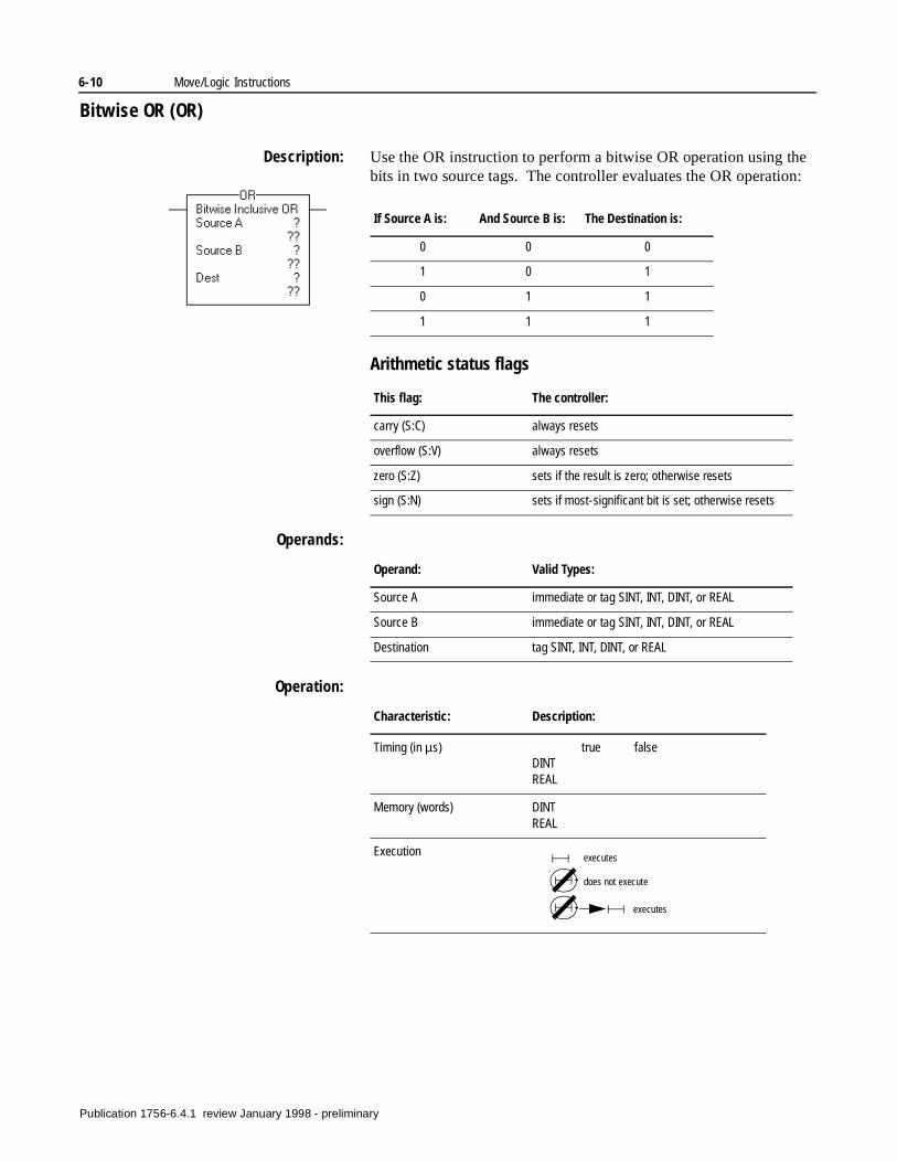
6-10 Move/Logic Instructions
Bitwise OR (OR)
Description: Use the OR instruction to perform a bitwise OR operation using the bits in two source tags. The controller evaluates the OR operation:
Arithmetic status flags
Operands:
Operation:
If Source A is: And Source B is: The Destination is:
0 0 0
1 0 1
0 1 1
1 1 1
This flag: The controller:
carry (S:C) always resets
overflow (S:V) always resets
zero (S:Z) sets if the result is zero; otherwise resets
sign (S:N) sets if most-significant bit is set; otherwise resets
Operand: Valid Types:
Source A immediate or tag SINT, INT, DINT, or REAL
Source B immediate or tag SINT, INT, DINT, or REAL
Destination tag SINT, INT, DINT, or REAL
Characteristic: Description:
Timing (in µs) true falseDINTREAL
Memory (words) DINTREAL
Execution executes
does not execute
executes
Publication 1756-6.4.1 review January 1998 - preliminary

Move/Logic Instructions 6-11
OR Example:
If the preceding instructions are true, the controller performs an OR operation on value_1 and value_2 and places the result in value_3.
0 0 0 0 0 0 0 0 0 0 1 0 1 0 1 0 1 0 1 0 1 1 1 1 1 1 1 1 1 1
0 0 0 0 0 0 0 0 0 0 1 1 1 1 1 1 1 1 1 1 0 0 0 0 0 0 0 0 0 0
0 0 0 0 0 0 0 0 0 0 1 1 1 1 1 1 1 1 1 1 1 1 1 1 1 1 1 1 1 1
value_1
value_2
value_3
Publication 1756-6.4.1 review January 1998 - preliminary
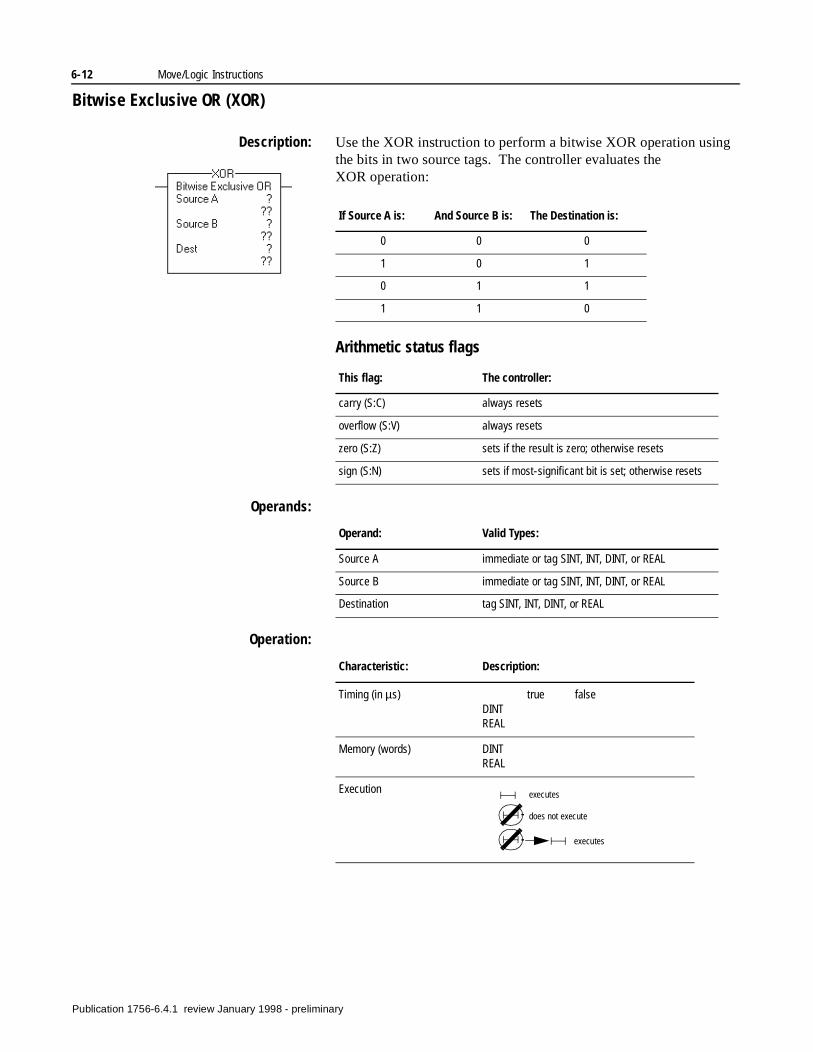
6-12 Move/Logic Instructions
Bitwise Exclusive OR (XOR)
Description: Use the XOR instruction to perform a bitwise XOR operation using the bits in two source tags. The controller evaluates the XOR operation:
Arithmetic status flags
Operands:
Operation:
If Source A is: And Source B is: The Destination is:
0 0 0
1 0 1
0 1 1
1 1 0
This flag: The controller:
carry (S:C) always resets
overflow (S:V) always resets
zero (S:Z) sets if the result is zero; otherwise resets
sign (S:N) sets if most-significant bit is set; otherwise resets
Operand: Valid Types:
Source A immediate or tag SINT, INT, DINT, or REAL
Source B immediate or tag SINT, INT, DINT, or REAL
Destination tag SINT, INT, DINT, or REAL
Characteristic: Description:
Timing (in µs) true falseDINTREAL
Memory (words) DINTREAL
Execution executes
does not execute
executes
Publication 1756-6.4.1 review January 1998 - preliminary
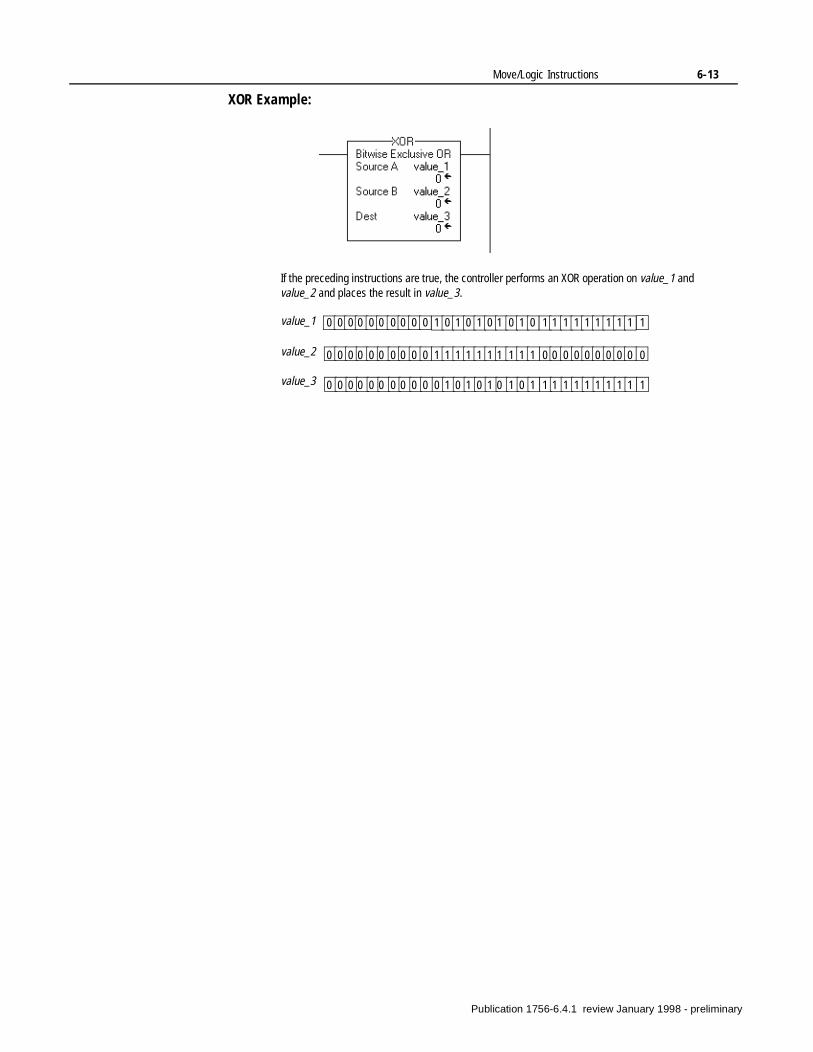
Move/Logic Instructions 6-13
XOR Example:
If the preceding instructions are true, the controller performs an XOR operation on value_1 and value_2 and places the result in value_3.
0 0 0 0 0 0 0 0 0 0 1 0 1 0 1 0 1 0 1 0 1 1 1 1 1 1 1 1 1 1
0 0 0 0 0 0 0 0 0 0 1 1 1 1 1 1 1 1 1 1 0 0 0 0 0 0 0 0 0 0
0 0 0 0 0 0 0 0 0 0 0 1 0 1 0 1 0 1 0 1 1 1 1 1 1 1 1 1 1 1
value_1
value_2
value_3
Publication 1756-6.4.1 review January 1998 - preliminary
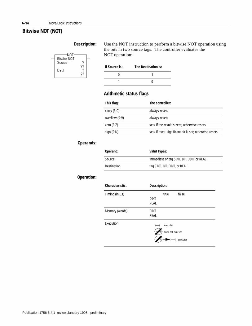
6-14 Move/Logic Instructions
Bitwise NOT (NOT)
Description: Use the NOT instruction to perform a bitwise NOT operation using the bits in two source tags. The controller evaluates the NOT operation:
Arithmetic status flags
Operands:
Operation:
If Source is: The Destination is:
0 1
1 0
This flag: The controller:
carry (S:C) always resets
overflow (S:V) always resets
zero (S:Z) sets if the result is zero; otherwise resets
sign (S:N) sets if most-significant bit is set; otherwise resets
Operand: Valid Types:
Source immediate or tag SINT, INT, DINT, or REAL
Destination tag SINT, INT, DINT, or REAL
Characteristic: Description:
Timing (in µs) true falseDINTREAL
Memory (words) DINTREAL
Execution executes
does not execute
executes
Publication 1756-6.4.1 review January 1998 - preliminary
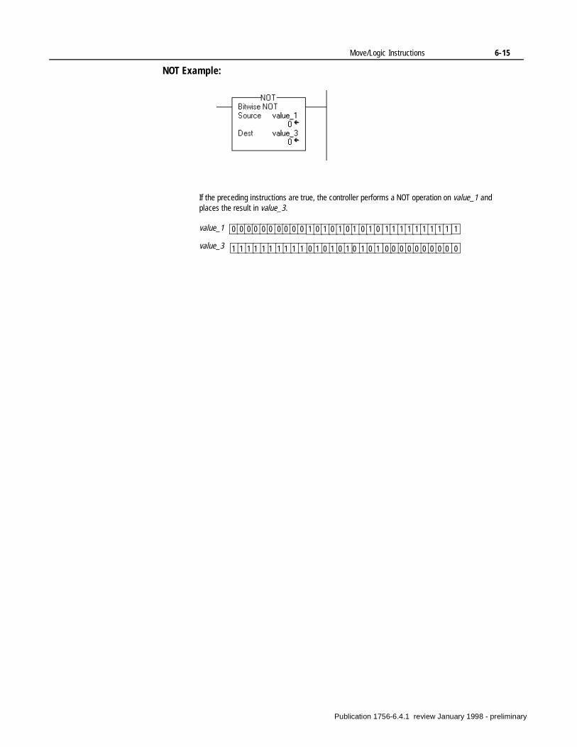
Move/Logic Instructions 6-15
NOT Example:
If the preceding instructions are true, the controller performs a NOT operation on value_1 and places the result in value_3.
0 0 0 0 0 0 0 0 0 0 1 0 1 0 1 0 1 0 1 0 1 1 1 1 1 1 1 1 1 1
1 1 1 1 1 1 1 1 1 1 0 1 0 1 0 1 0 1 0 1 0 0 0 0 0 0 0 0 0 0
value_1
value_3
Publication 1756-6.4.1 review January 1998 - preliminary

6-16 Move/Logic Instructions
Notes:
Publication 1756-6.4.1 review January 1998 - preliminary
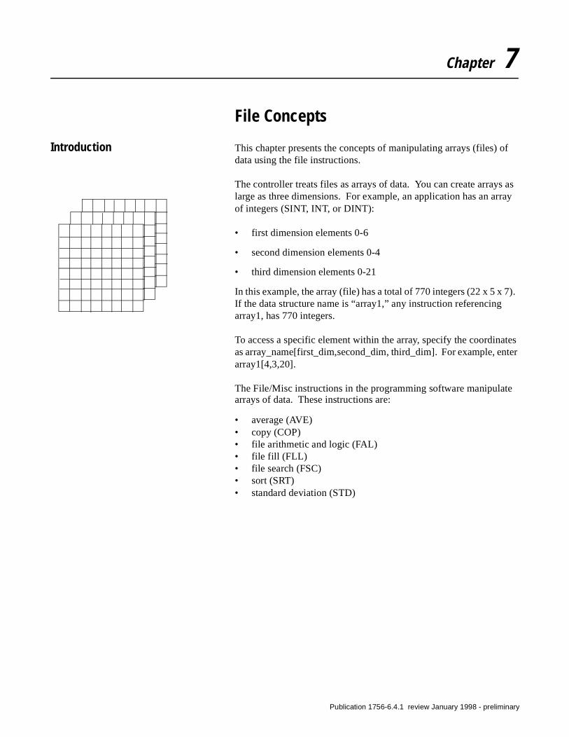
7).
tes ter
e
Chapter 7
File Concepts
Introduction This chapter presents the concepts of manipulating arrays (files) of data using the file instructions.
The controller treats files as arrays of data. You can create arrays as large as three dimensions. For example, an application has an array of integers (SINT, INT, or DINT):
• first dimension elements 0-6
• second dimension elements 0-4
• third dimension elements 0-21
In this example, the array (file) has a total of 770 integers (22 x 5 x If the data structure name is “array1,” any instruction referencing array1, has 770 integers.
To access a specific element within the array, specify the coordinaas array_name[first_dim,second_dim, third_dim]. For example, enarray1[4,3,20].
The File/Misc instructions in the programming software manipulatarrays of data. These instructions are:
• average (AVE)• copy (COP)• file arithmetic and logic (FAL)• file fill (FLL)• file search (FSC)• sort (SRT)• standard deviation (STD)
Publication 1756-6.4.1 review January 1998 - preliminary
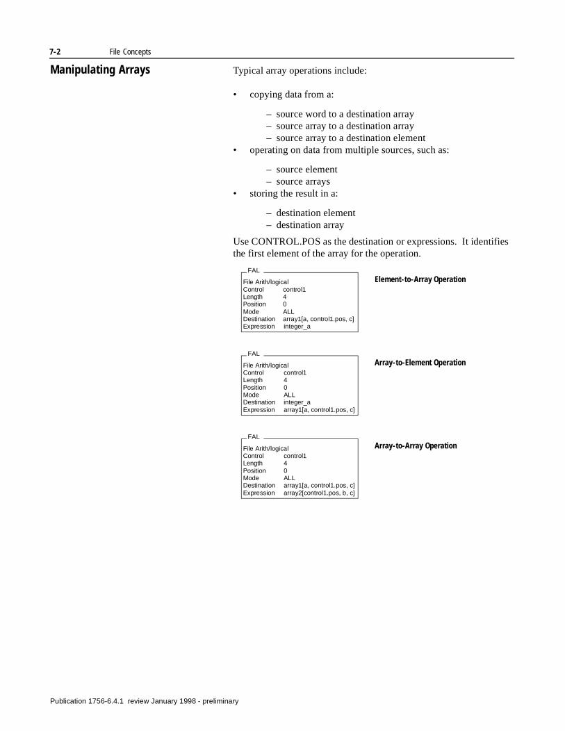
7-2 File Concepts
es
Manipulating Arrays Typical array operations include:
• copying data from a:
– source word to a destination array– source array to a destination array– source array to a destination element
• operating on data from multiple sources, such as:
– source element– source arrays
• storing the result in a:
– destination element– destination array
Use CONTROL.POS as the destination or expressions. It identifithe first element of the array for the operation.
FAL
File Arith/logicalControl control1Length 4Position 0Mode ALLDestination array1[a, control1.pos, c]Expression integer_a
FAL
File Arith/logicalControl control1Length 4Position 0Mode ALLDestination integer_aExpression array1[a, control1.pos, c]
FAL
File Arith/logicalControl control1Length 4Position 0Mode ALLDestination array1[a, control1.pos, c]Expression array2[control1.pos, b, c]
Element-to-Array Operation
Array-to-Element Operation
Array-to-Array Operation
Publication 1756-6.4.1 review January 1998 - preliminary
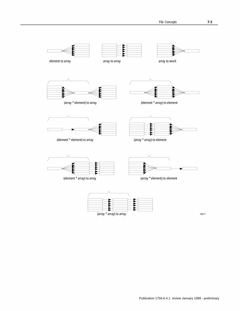
File Concepts 7-3
16617
element to array array to array array to word
(array * element) to array (element * array) to element
(element * element) to array (array * array) to element
(element * array) to array (array * element) to element
(array * array) to array
Publication 1756-6.4.1 review January 1998 - preliminary
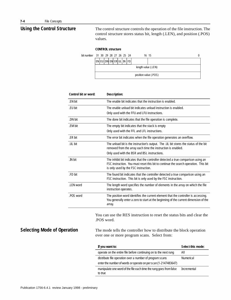
7-4 File Concepts
Using the Control Structure The control structure controls the operation of the file instruction. The control structure stores status bit, length (.LEN), and position (.POS) values.
You can use the RES instruction to reset the status bits and clear the .POS word.
Selecting Mode of Operation The mode tells the controller how to distribute the block operation over one or more program scans. Select from:
CONTROL structure
length value (.LEN)
position value (.POS)
EN EU DN EM ER UL IN FD
31 30 29 28 27 26 25 24 16 15 0bit number
Control bit or word: Description:
.EN bit The enable bit indicates that the instruction is enabled.
.EU bit The enable unload bit indicates unload instruction is enabled.
Only used with the FFU and LFU instructions.
.DN bit The done bit indicates that the file operation is complete.
.EM bit The empty bit indicates that the stack is empty
Only used with the FFL and LFL instructions.
.ER bit The error bit indicates when the file operation generates an overflow.
.UL bit The unload bit is the instruction’s output. The .UL bit stores the status of the bit removed from the array each time the instruction is enabled.
Only used with the BSR and BSL instructions.
.IN bit The inhibit bit indicates that the controller detected a true comparison using an FSC instruction. You must reset this bit to continue the search operation. This bit is only used by the FSC instruction.
.FD bit The found bit indicates that the controller detected a true comparison using an FSC instruction. This bit is only used by the FSC instruction.
.LEN word The length word specifies the number of elements in the array on which the file instruction operates.
.POS word The position word identifies the current element that the controller is accessing. You generally enter a zero to start at the beginning of the current dimension of the array.
If you want to: Select this mode:
operate on the entire file before continuing on to the next rung All
distribute file operation over a number of program scans
enter the number of words or operate on per scan (1-2147483647)
Numerical
manipulate one word of the file each time the rung goes from false to true
Incremental
Publication 1756-6.4.1 review January 1998 - preliminary
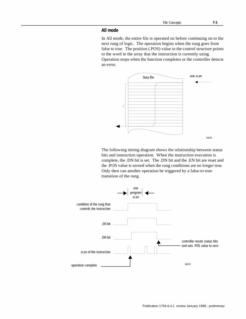
File Concepts 7-5
All mode
In All mode, the entire file is operated on before continuing on to the next rung of logic. The operation begins when the rung goes from false to true. The position (.POS) value in the control structure points to the word in the array that the instruction is currently using. Operation stops when the function completes or the controller detects an error.
The following timing diagram shows the relationship between status bits and instruction operation. When the instruction execution is complete, the .DN bit is set. The .DN bit and the .EN bit are reset and the .POS value is zeroed when the rung conditions are no longer true. Only then can another operation be triggered by a false-to-true transition of the rung.
Data file one scan
16639
oneprogram
scan
operation complete
controller resets status bits and sets .POS value to zero
condition of the rung thatcontrols the instruction
.EN bit
.DN bit
scan of the instruction
40010
Publication 1756-6.4.1 review January 1998 - preliminary
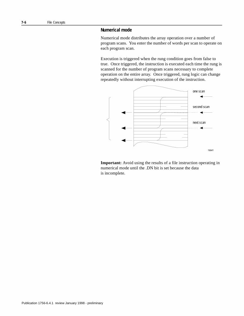
7-6 File Concepts
Numerical mode
Numerical mode distributes the array operation over a number of program scans. You enter the number of words per scan to operate on each program scan.
Execution is triggered when the rung condition goes from false to true. Once triggered, the instruction is executed each time the rung is scanned for the number of program scans necessary to complete operation on the entire array. Once triggered, rung logic can change repeatedly without interrupting execution of the instruction.
Important: Avoid using the results of a file instruction operating in numerical mode until the .DN bit is set because the data is incomplete.
one scan
16641
second scan
next scan
Publication 1756-6.4.1 review January 1998 - preliminary
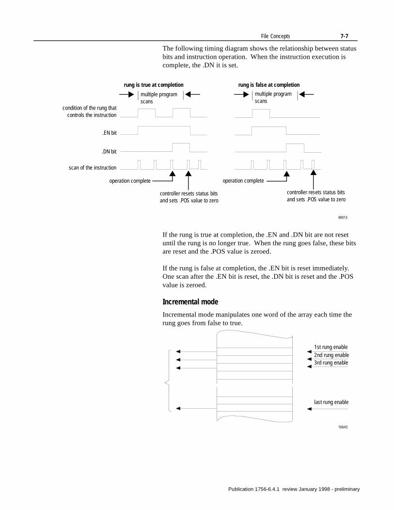
File Concepts 7-7
The following timing diagram shows the relationship between status bits and instruction operation. When the instruction execution is complete, the .DN it is set.
If the rung is true at completion, the .EN and .DN bit are not reset until the rung is no longer true. When the rung goes false, these bits are reset and the .POS value is zeroed.
If the rung is false at completion, the .EN bit is reset immediately. One scan after the .EN bit is reset, the .DN bit is reset and the .POS value is zeroed.
Incremental mode
Incremental mode manipulates one word of the array each time the rung goes from false to true.
multiple program scans
multiple program scans
condition of the rung thatcontrols the instruction
.EN bit
.DN bit
scan of the instruction
controller resets status bits and sets .POS value to zero
controller resets status bits and sets .POS value to zero
rung is true at completion rung is false at completion
40013
operation complete operation complete
16643
1st rung enable2nd rung enable3rd rung enable
last rung enable
Publication 1756-6.4.1 review January 1998 - preliminary
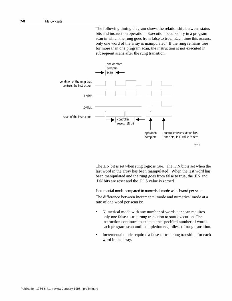
7-8 File Concepts
s ion.
ch
The following timing diagram shows the relationship between status bits and instruction operation. Execution occurs only in a program scan in which the rung goes from false to true. Each time this occurs, only one word of the array is manipulated. If the rung remains true for more than one program scan, the instruction is not executed in subsequent scans after the rung transition.
The .EN bit is set when rung logic is true. The .DN bit is set when the last word in the array has been manipulated. When the last word has been manipulated and the rung goes from false to true, the .EN and .DN bits are reset and the .POS value is zeroed.
Incremental mode compared to numerical mode with 1word per scan
The difference between incremental mode and numerical mode at a rate of one word per scan is:
• Numerical mode with any number of words per scan requires only one false-to-true rung transition to start execution. The instruction continues to execute the specified number of wordeach program scan until completion regardless of rung transit
• Incremental mode required a false-to-true rung transition for eaword in the array.
one or more program scan
condition of the rung thatcontrols the instruction
.EN bit
.DN bit
scan of the instructioncontroller resets .EN bit
operation complete
controller resets status bits and sets .POS value to zero
40014
Publication 1756-6.4.1 review January 1998 - preliminary
Chapter 8
File/Misc. Instructions(FAL, FSC, COP, FLL, AVE, SRT, STD)
Introduction The file/miscellaneous instructions operate on arrays of data.
If you move a REAL value to a SINT, INT, or DINT tag, the controller rounds the value to fit within the tag. The controller does not properly round numbers less than -1.
If you want to: Use this instruction: See page:
perform arithmetic, logic, shift, and function operations on array data
FAL 8-4
search for and compare array data FSC 8-7
copy the contents of one array into another array
COP 8-10
fill an array with specific data FLL 8-12
calculate the average of a set of values
AVE 8-13
sort one dimension of array data into ascending order
SRT 8-15
calculate the standard deviation of a set of values
STD 8-17
Publication 1756-6.4.1 review January 1998 - preliminary
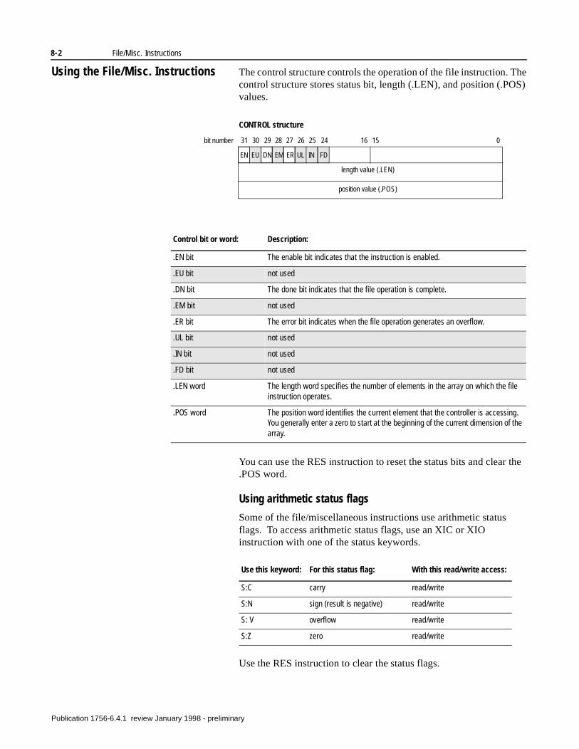
8-2 File/Misc. Instructions
Using the File/Misc. Instructions The control structure controls the operation of the file instruction. The control structure stores status bit, length (.LEN), and position (.POS) values.
You can use the RES instruction to reset the status bits and clear the .POS word.
Using arithmetic status flags
Some of the file/miscellaneous instructions use arithmetic status flags. To access arithmetic status flags, use an XIC or XIO instruction with one of the status keywords.
Use the RES instruction to clear the status flags.
CONTROL structure
length value (.LEN)
position value (.POS)
EN EU DN EM ER UL IN FD
31 30 29 28 27 26 25 24 16 15 0bit number
Control bit or word: Description:
.EN bit The enable bit indicates that the instruction is enabled.
.EU bit not used
.DN bit The done bit indicates that the file operation is complete.
.EM bit not used
.ER bit The error bit indicates when the file operation generates an overflow.
.UL bit not used
.IN bit not used
.FD bit not used
.LEN word The length word specifies the number of elements in the array on which the file instruction operates.
.POS word The position word identifies the current element that the controller is accessing. You generally enter a zero to start at the beginning of the current dimension of the array.
Use this keyword: For this status flag: With this read/write access:
S:C carry read/write
S:N sign (result is negative) read/write
S: V overflow read/write
S:Z zero read/write
Publication 1756-6.4.1 review January 1998 - preliminary
File/Misc. Instructions 8-3
Specifying dimensions within an array
The controller supports arrays of 1, 2, or 3 dimensions. Each time you enter an array tag for an instruction, you must also specify which dimension the instruction uses for its operations. You specify the active dimension of the array by using the .POS value of the CONTROL structure for the instruction.
The .POS value provides a sequential progression through the array. You could also use another tag or an immediate value to specify the position within the array. In this case, you would have to increment the position value.
Some file instructions operate on the right-most dimension only. Be careful when using these instructions with multiple-dimensional arrays to make sure the instruction operates on the data you intend. See the following chapters of file instructions to make sure you understand how the instructions operate.
Example array tag: Description:
array_1[control_1.pos] This is a single dimension array tag. The tag control_1.pos identifies the current position within the array.
array_2[0, control_2.pos] This is a 2-dimensional array. The instruction would operate on the second dimension. You can enter an immediate value or tag to identify the first dimension.
array_3[0,1,control_3.pos] This is a 3-dimensional array. The instruction would operate on the third dimension. You can enter an immediate value or tag to identify the first and second dimensions.
Publication 1756-6.4.1 review January 1998 - preliminary
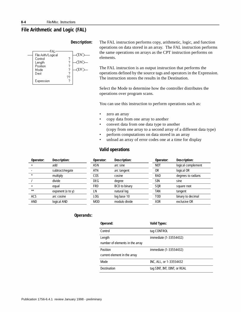
8-4 File/Misc. Instructions
File Arithmetic and Logic (FAL)
Description: The FAL instruction performs copy, arithmetic, logic, and function operations on data stored in an array. The FAL instruction performs the same operations on arrays as the CPT instruction performs on elements.
The FAL instruction is an output instruction that performs the operations defined by the source tags and operators in the Expression. The instruction stores the results in the Destination.
Select the Mode to determine how the controller distributes the operations over program scans.
You can use this instruction to perform operations such as:
• zero an array• copy data from one array to another• convert data from one data type to another
(copy from one array to a second array of a different data type)• perform computations on data stored in an array• unload an array of error codes one at a time for display
Valid operations
Operands:
Operator: Description:
+ add
- subtract/negate
* multiply
/ divide
= equal
** exponent (x to y)
ACS arc cosine
AND logical AND
ASN arc sine
ATN arc tangent
COS cosine
DEG degree
FRD BCD to binary
LN natural log
LOG log base 10
MOD modulo divide
Operator: Description:
NOT logical complement
OR logical OR
RAD degrees to radians
SIN sine
SQR square root
TAN tangent
TOD binary to decimal
XOR exclusive OR
Operator: Description:
Operand: Valid Types:
Control tag CONTROL
Length
number of elements in the array
immediate (1-33554432)
Position
current element in the array
immediate (1-33554432)
Mode INC, ALL, or 1-33554432
Destination tag SINT, INT, DINT, or REAL
Pu
blication 1756-6.4.1 review January 1998 - preliminary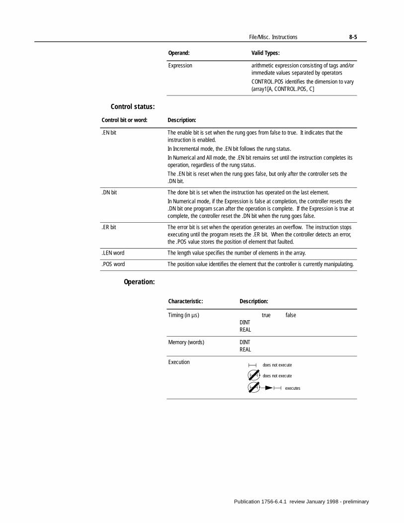
File/Misc. Instructions 8-5
Control status:
Operation:
Expression arithmetic expression consisting of tags and/or immediate values separated by operators
CONTROL.POS identifies the dimension to vary (array1[A, CONTROL.POS, C]
Operand: Valid Types:
Control bit or word: Description:
.EN bit The enable bit is set when the rung goes from false to true. It indicates that the instruction is enabled.
In Incremental mode, the .EN bit follows the rung status.
In Numerical and All mode, the .EN bit remains set until the instruction completes its operation, regardless of the rung status.
The .EN bit is reset when the rung goes false, but only after the controller sets the .DN bit.
.DN bit The done bit is set when the instruction has operated on the last element.
In Numerical mode, if the Expression is false at completion, the controller resets the .DN bit one program scan after the operation is complete. If the Expression is true at complete, the controller reset the .DN bit when the rung goes false.
.ER bit The error bit is set when the operation generates an overflow. The instruction stops executing until the program resets the .ER bit. When the controller detects an error, the .POS value stores the position of element that faulted.
.LEN word The length value specifies the number of elements in the array.
.POS word The position value identifies the element that the controller is currently manipulating.
Characteristic: Description:
Timing (in µs) true falseDINTREAL
Memory (words) DINTREAL
Execution does not execute
does not execute
executes
Publication 1756-6.4.1 review January 1998 - preliminary
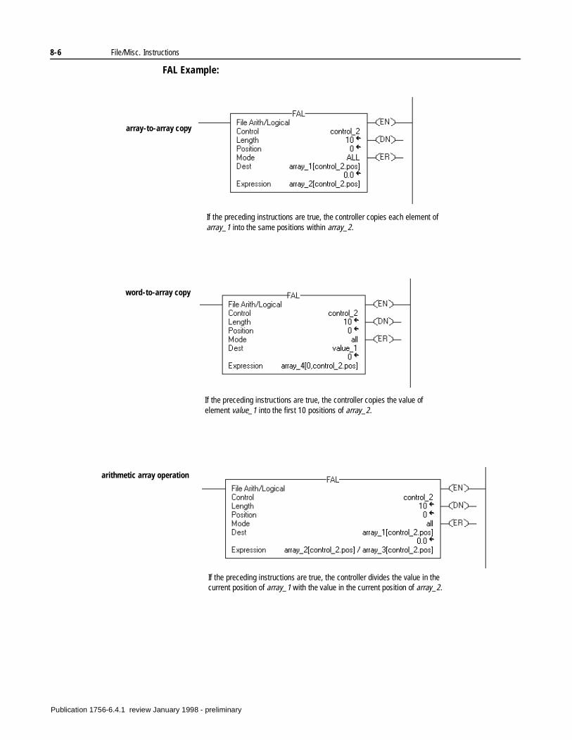
8-6 File/Misc. Instructions
FAL Example:
If the preceding instructions are true, the controller copies each element of array_1 into the same positions within array_2.
array-to-array copy
word-to-array copy
If the preceding instructions are true, the controller copies the value of element value_1 into the first 10 positions of array_2.
arithmetic array operation
If the preceding instructions are true, the controller divides the value in the current position of array_1 with the value in the current position of array_2.
Publication 1756-6.4.1 review January 1998 - preliminary
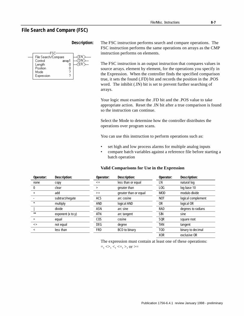
File/Misc. Instructions 8-7
File Search and Compare (FSC)
Description: The FSC instruction performs search and compare operations. The FSC instruction performs the same operations on arrays as the CMP instruction performs on elements.
The FSC instruction is an output instruction that compares values in source arrays. element by element, for the operations you specify in the Expression. When the controller finds the specified comparison true, it sets the found (.FD) bit and records the position in the .POS word. The inhibit (.IN) bit is set to prevent further searching of arrays.
Your logic must examine the .FD bit and the .POS value to take appropriate action. Reset the .IN bit after a true comparison is found so the instruction can continue.
Select the Mode to determine how the controller distributes the operations over program scans.
You can use this instruction to perform operations such as:
• set high and low process alarms for multiple analog inputs• compare batch variables against a reference file before starting a
batch operation
Valid Comparisons for Use in the Expression
The expression must contain at least one of these operations: =, <>, <, <=, >, or >=
Operator: Description:none copy
0 clear
+ add
- subtract/negate
* multiply
| divide
** exponent (x to y)
= equal
<> not equal
< less than
<= less than or equal
> greater than
>= greater than or equal
ACS arc cosine
AND logical AND
ASN arc sine
ATN arc tangent
COS cosine
DEG degree
FRD BCD to binary
Operator: Description:LN natural log
LOG log base 10
MOD modulo divide
NOT logical complement
OR logical OR
RAD degrees to radians
SIN sine
SQR square root
TAN tangent
TOD binary to decimal
XOR exclusive OR
Operator: Description:
Publication 1756-6.4.1 review January 1998 - preliminary
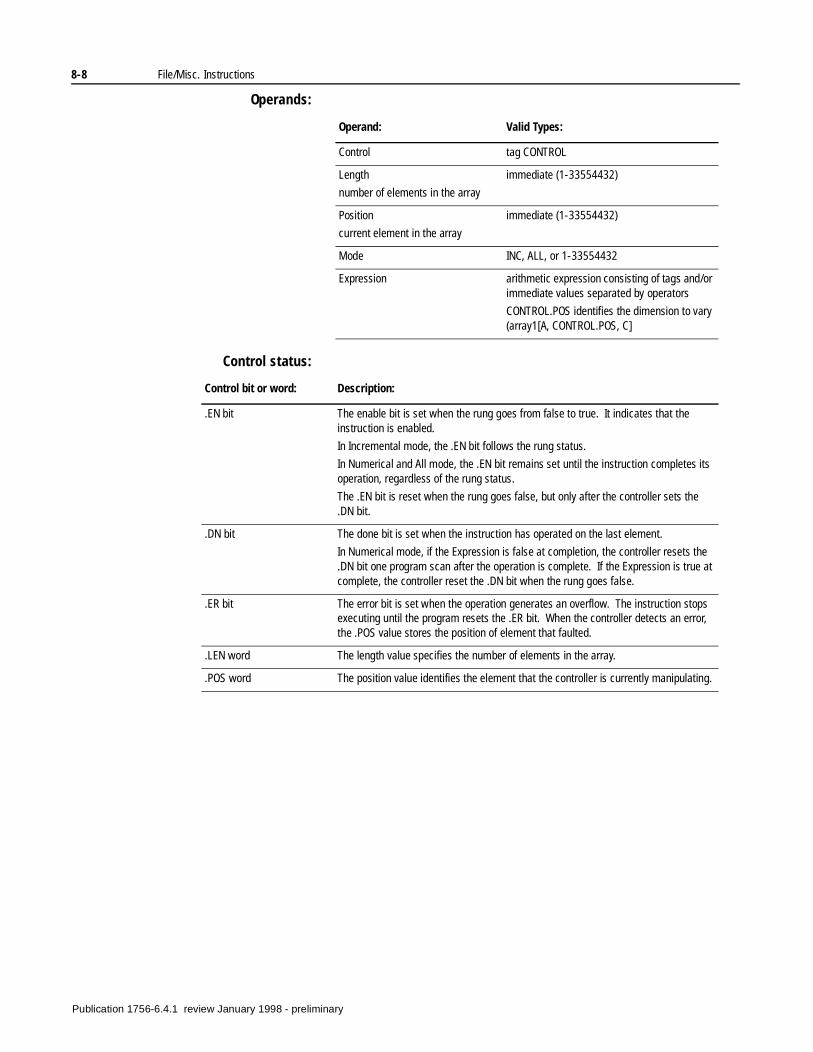
8-8 File/Misc. Instructions
Operands:
Control status:
Operand: Valid Types:
Control tag CONTROL
Length
number of elements in the array
immediate (1-33554432)
Position
current element in the array
immediate (1-33554432)
Mode INC, ALL, or 1-33554432
Expression arithmetic expression consisting of tags and/or immediate values separated by operators
CONTROL.POS identifies the dimension to vary (array1[A, CONTROL.POS, C]
Control bit or word: Description:
.EN bit The enable bit is set when the rung goes from false to true. It indicates that the instruction is enabled.
In Incremental mode, the .EN bit follows the rung status.
In Numerical and All mode, the .EN bit remains set until the instruction completes its operation, regardless of the rung status.
The .EN bit is reset when the rung goes false, but only after the controller sets the .DN bit.
.DN bit The done bit is set when the instruction has operated on the last element.
In Numerical mode, if the Expression is false at completion, the controller resets the .DN bit one program scan after the operation is complete. If the Expression is true at complete, the controller reset the .DN bit when the rung goes false.
.ER bit The error bit is set when the operation generates an overflow. The instruction stops executing until the program resets the .ER bit. When the controller detects an error, the .POS value stores the position of element that faulted.
.LEN word The length value specifies the number of elements in the array.
.POS word The position value identifies the element that the controller is currently manipulating.
Publication 1756-6.4.1 review January 1998 - preliminary
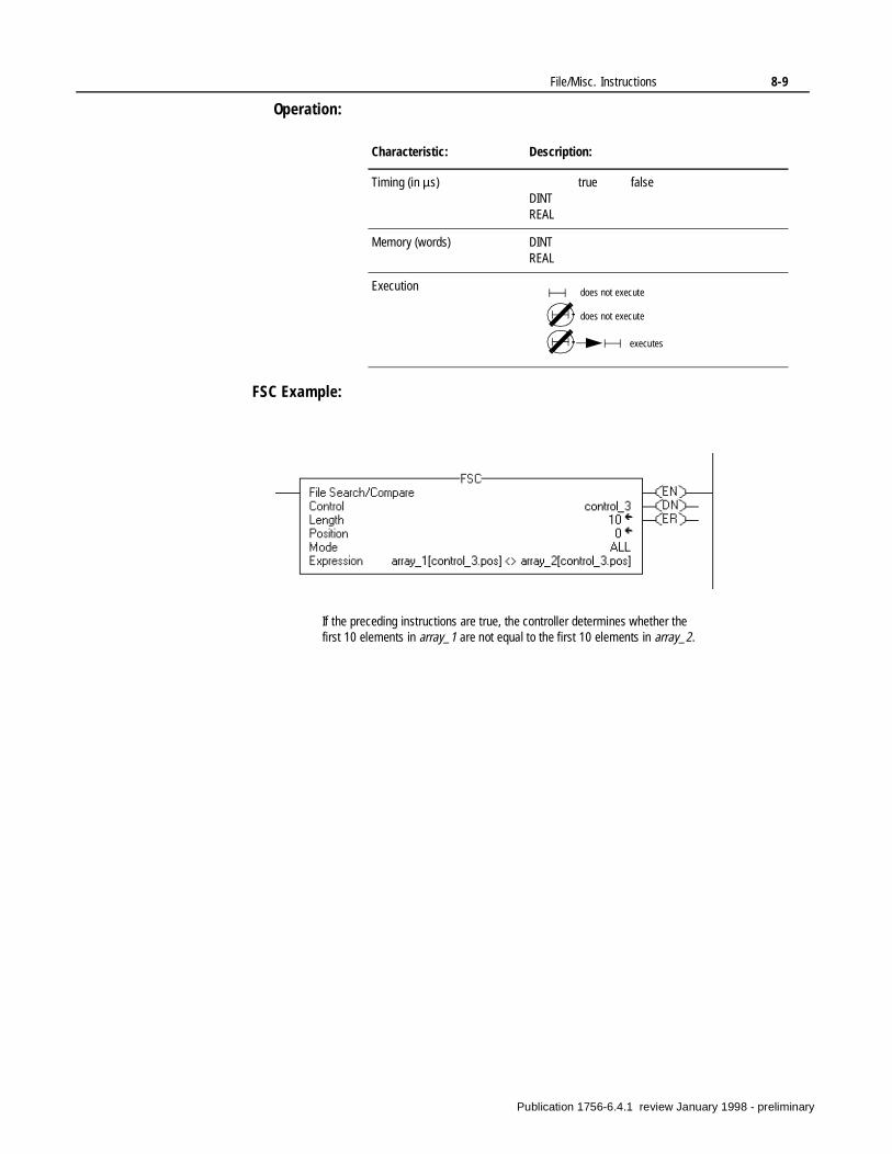
File/Misc. Instructions 8-9
Operation:
FSC Example:
Characteristic: Description:
Timing (in µs) true falseDINTREAL
Memory (words) DINTREAL
Execution does not execute
does not execute
executes
If the preceding instructions are true, the controller determines whether the first 10 elements in array_1 are not equal to the first 10 elements in array_2.
Publication 1756-6.4.1 review January 1998 - preliminary
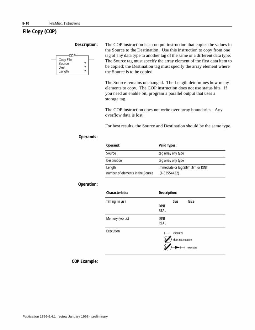
8-10 File/Misc. Instructions
File Copy (COP)
Description: The COP instruction is an output instruction that copies the values in the Source to the Destination. Use this instruction to copy from one tag of any data type to another tag of the same or a different data type. The Source tag must specify the array element of the first data item to be copied; the Destination tag must specify the array element where the Source is to be copied.
The Source remains unchanged. The Length determines how many elements to copy. The COP instruction does not use status bits. If you need an enable bit, program a parallel output that uses a storage tag.
The COP instruction does not write over array boundaries. Any overflow data is lost.
For best results, the Source and Destination should be the same type.
Operands:
Operation:
COP Example:
Operand: Valid Types:
Source tag array any type
Destination tag array any type
Length
number of elements in the Source
immediate or tag SINT, INT, or DINT
(1-33554432)
Characteristic: Description:
Timing (in µs) true falseDINTREAL
Memory (words) DINTREAL
Execution executes
does not execute
executes
Publication 1756-6.4.1 review January 1998 - preliminary

File/Misc. Instructions 8-11
If the preceding instructions are true, the controller copies the first 10 elements of the second dimension of array_4 into the first 10 elements of the second dimension of array_5.
Publication 1756-6.4.1 review January 1998 - preliminary
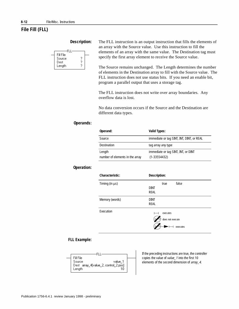
8-12 File/Misc. Instructions
File Fill (FLL)
Description: The FLL instruction is an output instruction that fills the elements of an array with the Source value. Use this instruction to fill the elements of an array with the same value. The Destination tag must specify the first array element to receive the Source value.
The Source remains unchanged. The Length determines the number of elements in the Destination array to fill with the Source value. The FLL instruction does not use status bits. If you need an enable bit, program a parallel output that uses a storage tag.
The FLL instruction does not write over array boundaries. Any overflow data is lost.
No data conversion occurs if the Source and the Destination are different data types.
Operands:
Operation:
FLL Example:
Operand: Valid Types:
Source immediate or tag SINT, INT, DINT, or REAL
Destination tag array any type
Length
number of elements in the array
immediate or tag SINT, INT, or DINT
(1-33554432)
Characteristic: Description:
Timing (in µs) true falseDINTREAL
Memory (words) DINTREAL
Execution executes
does not execute
executes
If the preceding instructions are true, the controller copies the value of value_1 into the first 10 elements of the second dimension of array_4.
Publication 1756-6.4.1 review January 1998 - preliminary
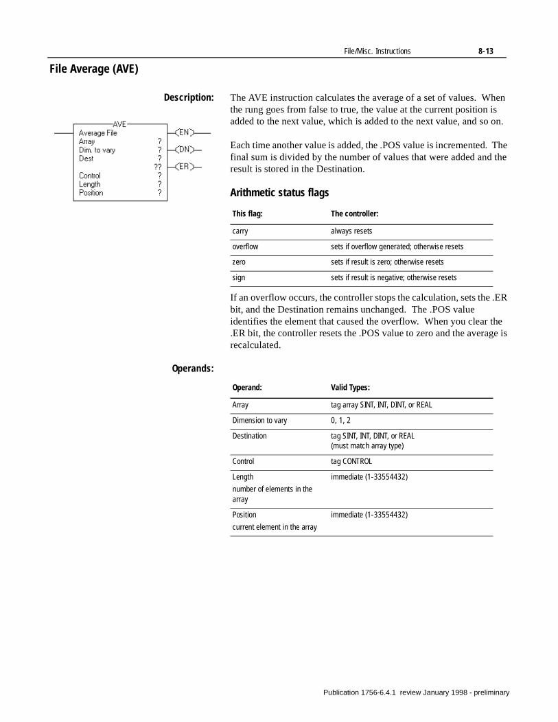
File/Misc. Instructions 8-13
File Average (AVE)
Description: The AVE instruction calculates the average of a set of values. When the rung goes from false to true, the value at the current position is added to the next value, which is added to the next value, and so on.
Each time another value is added, the .POS value is incremented. The final sum is divided by the number of values that were added and the result is stored in the Destination.
Arithmetic status flags
If an overflow occurs, the controller stops the calculation, sets the .ER bit, and the Destination remains unchanged. The .POS value identifies the element that caused the overflow. When you clear the .ER bit, the controller resets the .POS value to zero and the average is recalculated.
Operands:
This flag: The controller:
carry always resets
overflow sets if overflow generated; otherwise resets
zero sets if result is zero; otherwise resets
sign sets if result is negative; otherwise resets
Operand: Valid Types:
Array tag array SINT, INT, DINT, or REAL
Dimension to vary 0, 1, 2
Destination tag SINT, INT, DINT, or REAL(must match array type)
Control tag CONTROL
Length
number of elements in the array
immediate (1-33554432)
Position
current element in the array
immediate (1-33554432)
Publication 1756-6.4.1 review January 1998 - preliminary
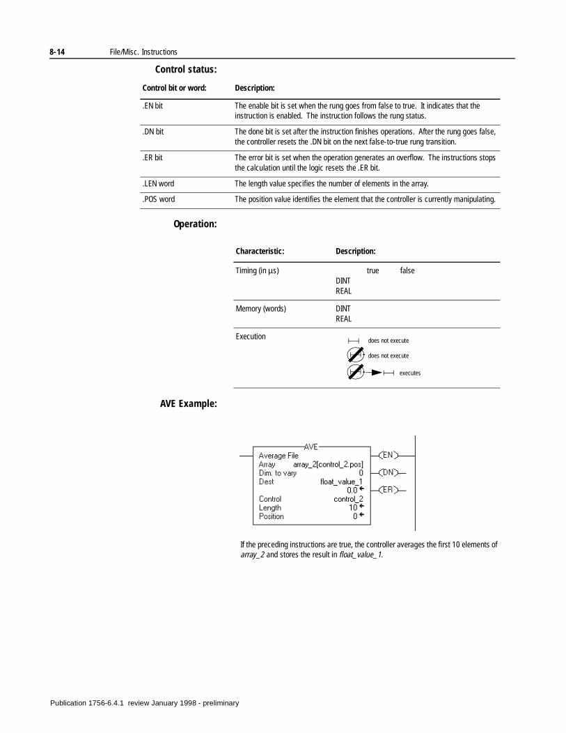
8-14 File/Misc. Instructions
Control status:
Operation:
AVE Example:
Control bit or word: Description:
.EN bit The enable bit is set when the rung goes from false to true. It indicates that the instruction is enabled. The instruction follows the rung status.
.DN bit The done bit is set after the instruction finishes operations. After the rung goes false, the controller resets the .DN bit on the next false-to-true rung transition.
.ER bit The error bit is set when the operation generates an overflow. The instructions stops the calculation until the logic resets the .ER bit.
.LEN word The length value specifies the number of elements in the array.
.POS word The position value identifies the element that the controller is currently manipulating.
Characteristic: Description:
Timing (in µs) true falseDINTREAL
Memory (words) DINTREAL
Execution does not execute
does not execute
executes
If the preceding instructions are true, the controller averages the first 10 elements of array_2 and stores the result in float_value_1.
Publication 1756-6.4.1 review January 1998 - preliminary
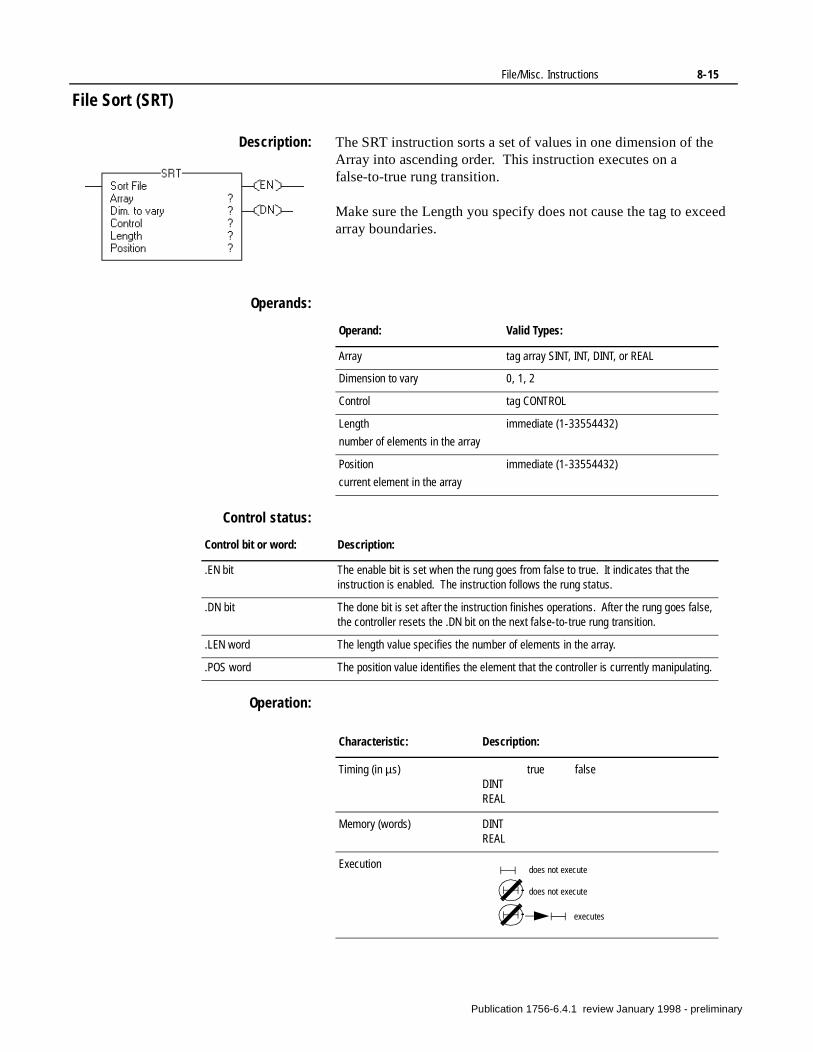
File/Misc. Instructions 8-15
File Sort (SRT)
Description: The SRT instruction sorts a set of values in one dimension of the Array into ascending order. This instruction executes on a false-to-true rung transition.
Make sure the Length you specify does not cause the tag to exceed array boundaries.
Operands:
Control status:
Operation:
Operand: Valid Types:
Array tag array SINT, INT, DINT, or REAL
Dimension to vary 0, 1, 2
Control tag CONTROL
Length
number of elements in the array
immediate (1-33554432)
Position
current element in the array
immediate (1-33554432)
Control bit or word: Description:
.EN bit The enable bit is set when the rung goes from false to true. It indicates that the instruction is enabled. The instruction follows the rung status.
.DN bit The done bit is set after the instruction finishes operations. After the rung goes false, the controller resets the .DN bit on the next false-to-true rung transition.
.LEN word The length value specifies the number of elements in the array.
.POS word The position value identifies the element that the controller is currently manipulating.
Characteristic: Description:
Timing (in µs) true falseDINTREAL
Memory (words) DINTREAL
Execution does not execute
does not execute
executes
Publication 1756-6.4.1 review January 1998 - preliminary
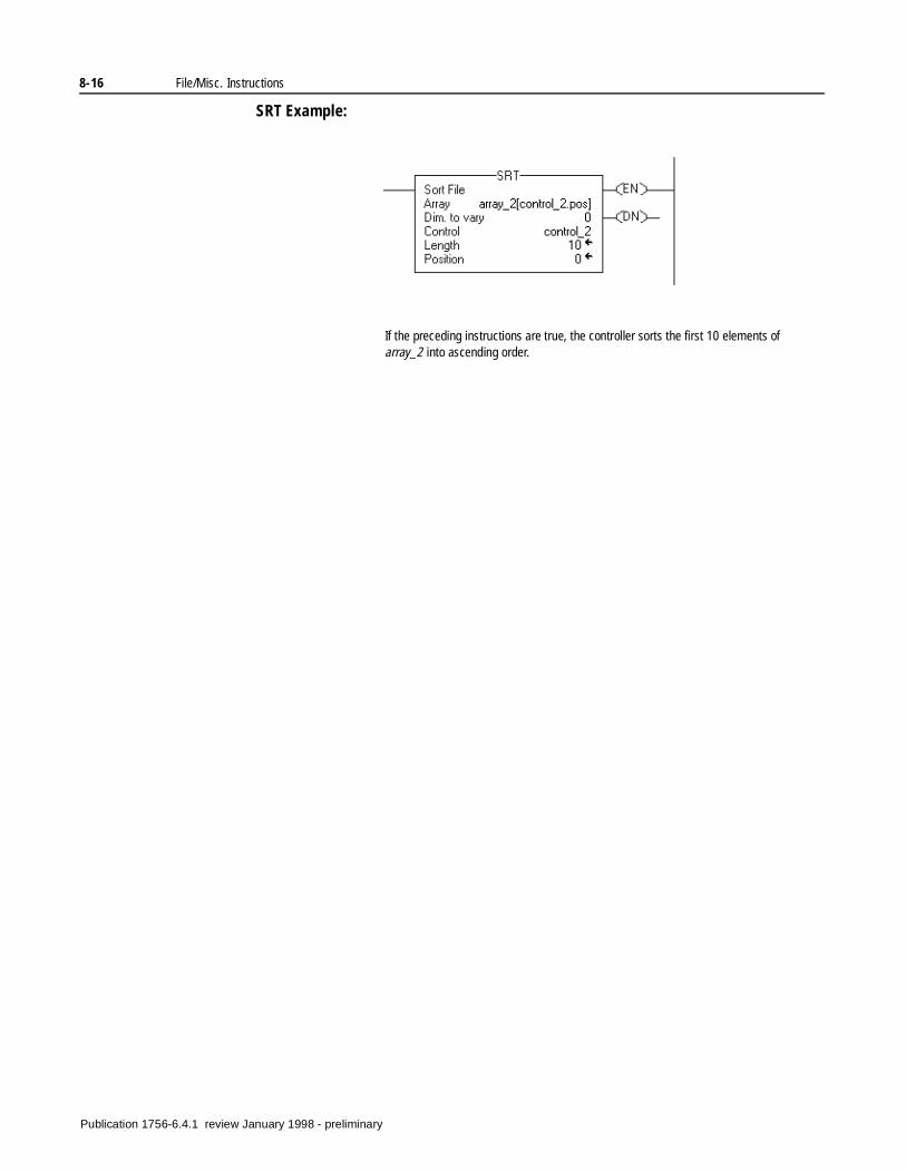
8-16 File/Misc. Instructions
SRT Example:
If the preceding instructions are true, the controller sorts the first 10 elements of array_2 into ascending order.
Publication 1756-6.4.1 review January 1998 - preliminary
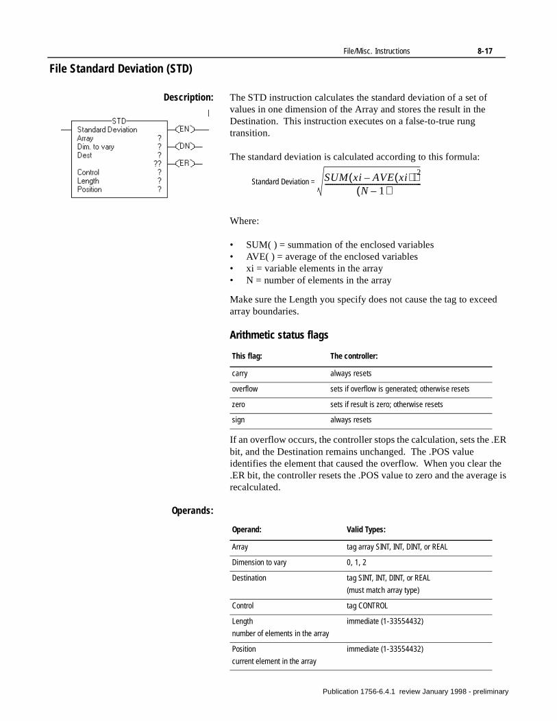
File/Misc. Instructions 8-17
ed
.ER
he
File Standard Deviation (STD)
Description: The STD instruction calculates the standard deviation of a set of values in one dimension of the Array and stores the result in the Destination. This instruction executes on a false-to-true rung transition.
The standard deviation is calculated according to this formula:
Where:
• SUM( ) = summation of the enclosed variables• AVE( ) = average of the enclosed variables• xi = variable elements in the array• N = number of elements in the array
Make sure the Length you specify does not cause the tag to excearray boundaries.
Arithmetic status flags
If an overflow occurs, the controller stops the calculation, sets the bit, and the Destination remains unchanged. The .POS value identifies the element that caused the overflow. When you clear t.ER bit, the controller resets the .POS value to zero and the average isrecalculated.
Operands:
This flag: The controller:
carry always resets
overflow sets if overflow is generated; otherwise resets
zero sets if result is zero; otherwise resets
sign always resets
SUM xi AVE xi( )–( )2
N 1–( )-----------------------------------------------------Standard Deviation =
Operand: Valid Types:
Array tag array SINT, INT, DINT, or REAL
Dimension to vary 0, 1, 2
Destination tag SINT, INT, DINT, or REAL
(must match array type)
Control tag CONTROL
Length
number of elements in the array
immediate (1-33554432)
Position
current element in the array
immediate (1-33554432)
Publication 1756-6.4.1 review January 1998 - preliminary
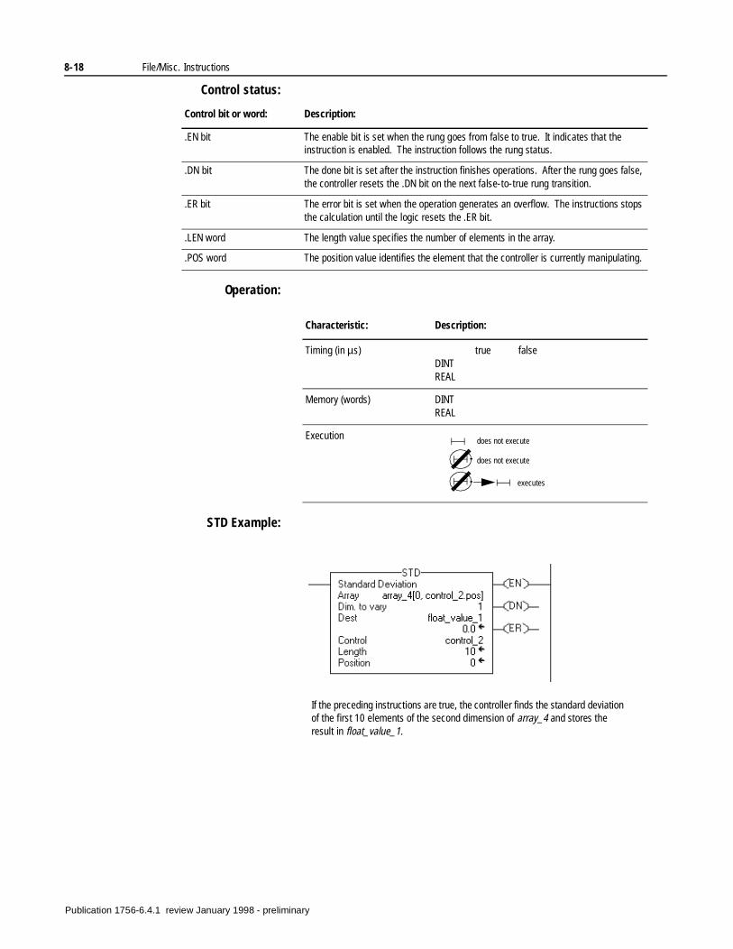
8-18 File/Misc. Instructions
Control status:
Operation:
STD Example:
Control bit or word: Description:
.EN bit The enable bit is set when the rung goes from false to true. It indicates that the instruction is enabled. The instruction follows the rung status.
.DN bit The done bit is set after the instruction finishes operations. After the rung goes false, the controller resets the .DN bit on the next false-to-true rung transition.
.ER bit The error bit is set when the operation generates an overflow. The instructions stops the calculation until the logic resets the .ER bit.
.LEN word The length value specifies the number of elements in the array.
.POS word The position value identifies the element that the controller is currently manipulating.
Characteristic: Description:
Timing (in µs) true falseDINTREAL
Memory (words) DINTREAL
Execution does not execute
does not execute
executes
If the preceding instructions are true, the controller finds the standard deviation of the first 10 elements of the second dimension of array_4 and stores the result in float_value_1.
Publication 1756-6.4.1 review January 1998 - preliminary
Chapter 9
File/Shift Instructions(BSL, BSR, FFL, FFU, LFL, LFU)
Introduction Use the file/shift instructions to track the flow of parts and information.
If you want to: Use this instruction: See page:
Load bits into, shift bits through, and unload bits from a bit array one bit at a time, such as for tracking bottles through a line where each bit represents a bottle.
BSL 9-3
BSR 9-5
Load and unload values in the same order, such as for tracking parts through an assembly line where parts are represented by values that have a part numbers and assembly code.
FFL 9-7
FFU 9-9
Load and unload values in reverse order, such as tracking stacked inventory in a warehouse where goods are represented by a serial numbers and inventory codes.
LFL 9-11
LFU 9-13
Publication 1756-6.4.1 review January 1998 - preliminary
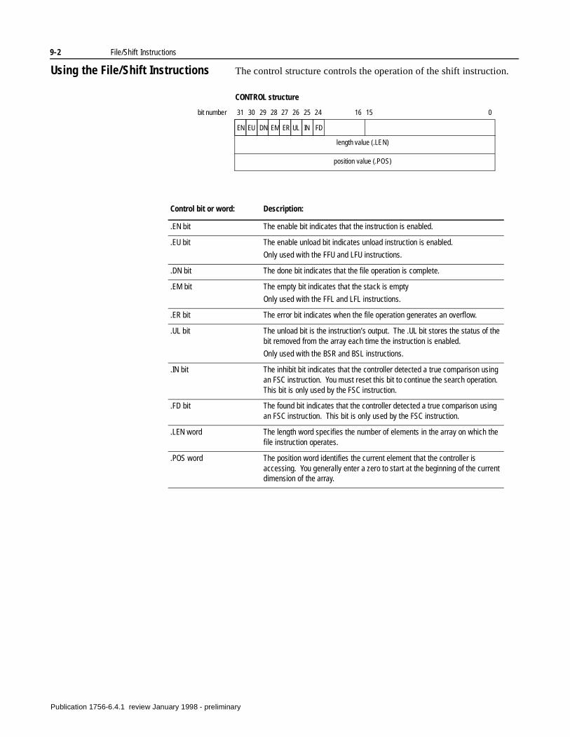
9-2 File/Shift Instructions
Using the File/Shift Instructions The control structure controls the operation of the shift instruction.
CONTROL structure
length value (.LEN)
position value (.POS)
EN EU DN EM ER UL IN FD
31 30 29 28 27 26 25 24 16 15 0bit number
Control bit or word: Description:
.EN bit The enable bit indicates that the instruction is enabled.
.EU bit The enable unload bit indicates unload instruction is enabled.
Only used with the FFU and LFU instructions.
.DN bit The done bit indicates that the file operation is complete.
.EM bit The empty bit indicates that the stack is empty
Only used with the FFL and LFL instructions.
.ER bit The error bit indicates when the file operation generates an overflow.
.UL bit The unload bit is the instruction’s output. The .UL bit stores the status of the bit removed from the array each time the instruction is enabled.
Only used with the BSR and BSL instructions.
.IN bit The inhibit bit indicates that the controller detected a true comparison using an FSC instruction. You must reset this bit to continue the search operation. This bit is only used by the FSC instruction.
.FD bit The found bit indicates that the controller detected a true comparison using an FSC instruction. This bit is only used by the FSC instruction.
.LEN word The length word specifies the number of elements in the array on which the file instruction operates.
.POS word The position word identifies the current element that the controller is accessing. You generally enter a zero to start at the beginning of the current dimension of the array.
Publication 1756-6.4.1 review January 1998 - preliminary
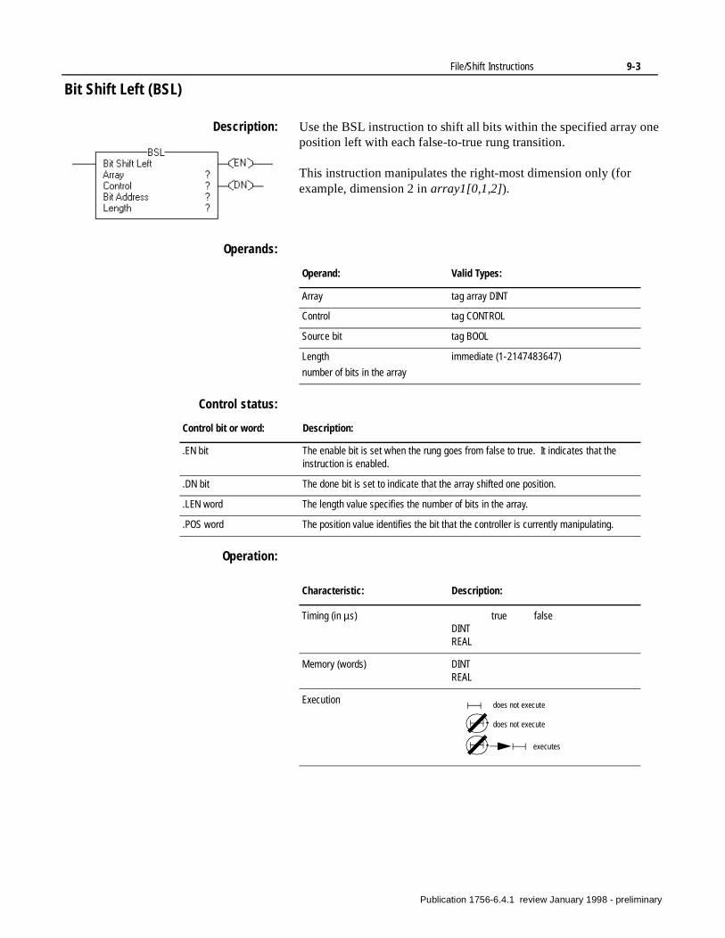
File/Shift Instructions 9-3
Bit Shift Left (BSL)
Description: Use the BSL instruction to shift all bits within the specified array one position left with each false-to-true rung transition.
This instruction manipulates the right-most dimension only (for example, dimension 2 in array1[0,1,2]).
Operands:
Control status:
Operation:
Operand: Valid Types:
Array tag array DINT
Control tag CONTROL
Source bit tag BOOL
Length
number of bits in the array
immediate (1-2147483647)
Control bit or word: Description:
.EN bit The enable bit is set when the rung goes from false to true. It indicates that the instruction is enabled.
.DN bit The done bit is set to indicate that the array shifted one position.
.LEN word The length value specifies the number of bits in the array.
.POS word The position value identifies the bit that the controller is currently manipulating.
Characteristic: Description:
Timing (in µs) true falseDINTREAL
Memory (words) DINTREAL
Execution does not execute
does not execute
executes
Publication 1756-6.4.1 review January 1998 - preliminary
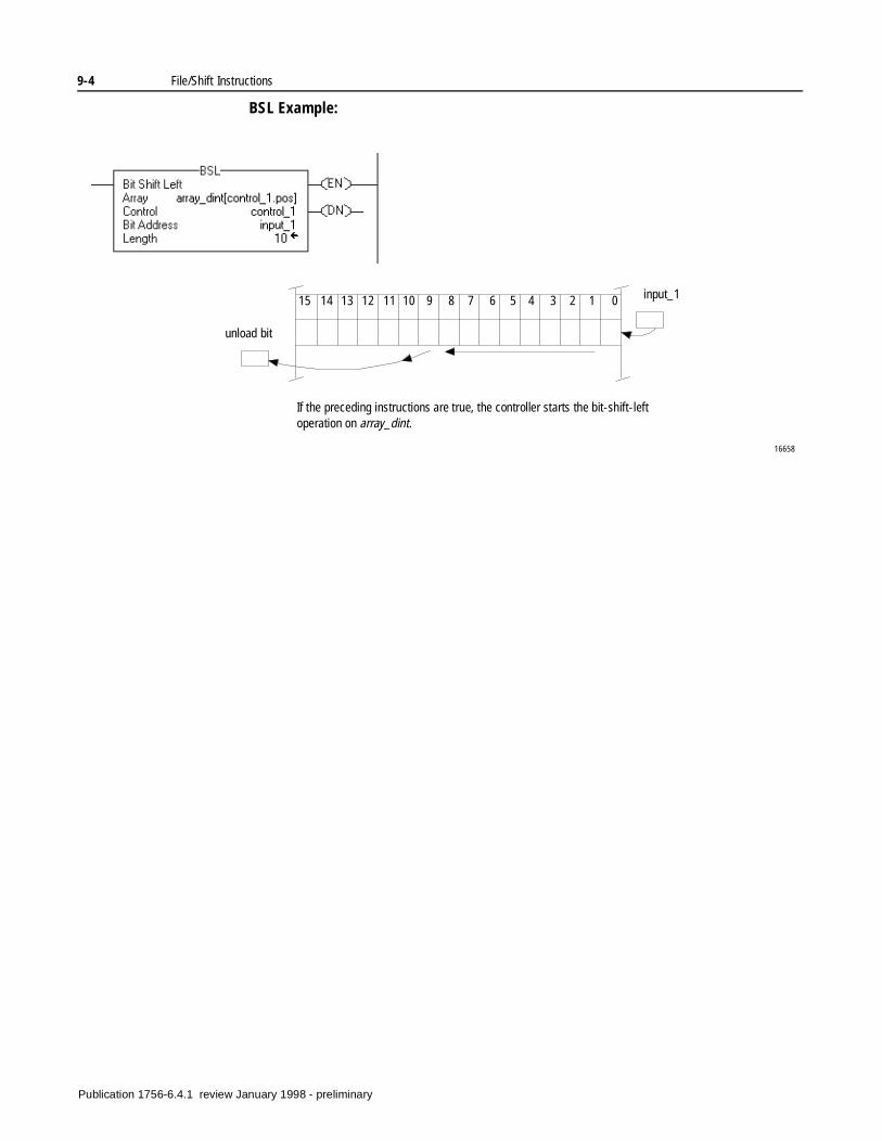
9-4 File/Shift Instructions
BSL Example:
If the preceding instructions are true, the controller starts the bit-shift-left operation on array_dint.
unload bit
input_115 14 13 12 11 10 9 8 7 6 5 4 3 2 1 0
16658
Publication 1756-6.4.1 review January 1998 - preliminary
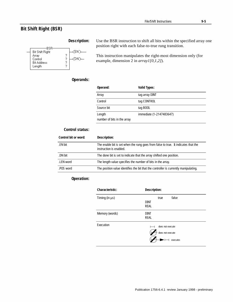
File/Shift Instructions 9-5
Bit Shift Right (BSR)
Description: Use the BSR instruction to shift all bits within the specified array one position right with each false-to-true rung transition.
This instruction manipulates the right-most dimension only (for example, dimension 2 in array1[0,1,2]).
Operands:
Control status:
Operation:
Operand: Valid Types:
Array tag array DINT
Control tag CONTROL
Source bit tag BOOL
Length
number of bits in the array
immediate (1-2147483647)
Control bit or word: Description:
.EN bit The enable bit is set when the rung goes from false to true. It indicates that the instruction is enabled.
.DN bit The done bit is set to indicate that the array shifted one position.
.LEN word The length value specifies the number of bits in the array.
.POS word The position value identifies the bit that the controller is currently manipulating.
Characteristic: Description:
Timing (in µs) true falseDINTREAL
Memory (words) DINTREAL
Execution does not execute
does not execute
executes
Publication 1756-6.4.1 review January 1998 - preliminary
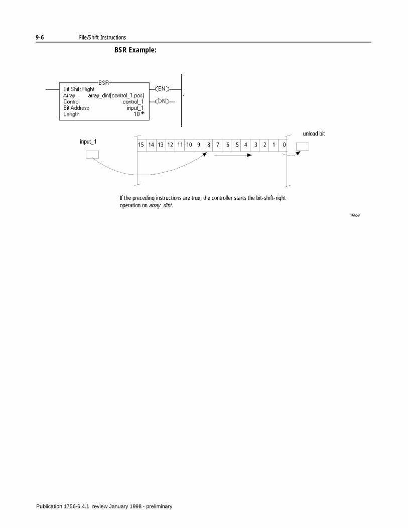
9-6 File/Shift Instructions
BSR Example:
If the preceding instructions are true, the controller starts the bit-shift-right operation on array_dint.
unload bitinput_1 15 14 13 12 11 10 9 8 7 6 5 4 3 2 1 0
16659
Publication 1756-6.4.1 review January 1998 - preliminary
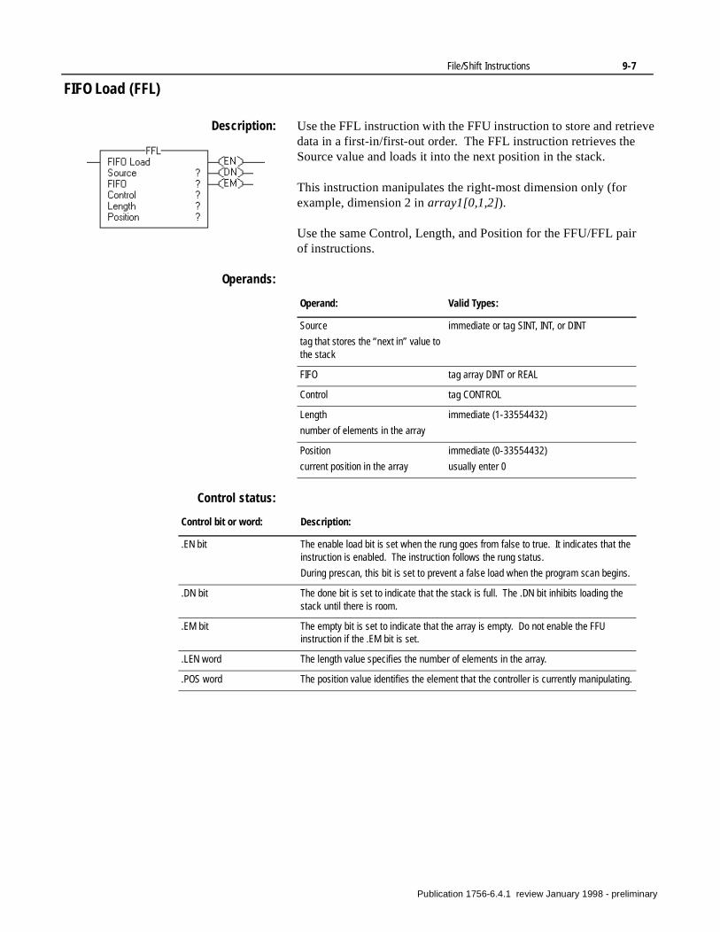
File/Shift Instructions 9-7
FIFO Load (FFL)
Description: Use the FFL instruction with the FFU instruction to store and retrieve data in a first-in/first-out order. The FFL instruction retrieves the Source value and loads it into the next position in the stack.
This instruction manipulates the right-most dimension only (for example, dimension 2 in array1[0,1,2]).
Use the same Control, Length, and Position for the FFU/FFL pair of instructions.
Operands:
Control status:
Operand: Valid Types:
Source
tag that stores the “next in” value to the stack
immediate or tag SINT, INT, or DINT
FIFO tag array DINT or REAL
Control tag CONTROL
Length
number of elements in the array
immediate (1-33554432)
Position
current position in the array
immediate (0-33554432)
usually enter 0
Control bit or word: Description:
.EN bit The enable load bit is set when the rung goes from false to true. It indicates that the instruction is enabled. The instruction follows the rung status.
During prescan, this bit is set to prevent a false load when the program scan begins.
.DN bit The done bit is set to indicate that the stack is full. The .DN bit inhibits loading the stack until there is room.
.EM bit The empty bit is set to indicate that the array is empty. Do not enable the FFU instruction if the .EM bit is set.
.LEN word The length value specifies the number of elements in the array.
.POS word The position value identifies the element that the controller is currently manipulating.
Publication 1756-6.4.1 review January 1998 - preliminary

9-8 File/Shift Instructions
Operation:
FFL/FFU Example:
Characteristic: Description:
Timing (in µs) true falseDINTREAL
Memory (words) DINTREAL
Execution does not execute
does not execute
executes
If the preceding instructions are true, the controller starts the FIFO operation on array_dint.
16660
array_dint
source (value_1)
destination (value_2)
FFU removes data from the stack
FFL places data in the stack
Publication 1756-6.4.1 review January 1998 - preliminary

File/Shift Instructions 9-9
FIFO Unload (FFU)
Description: Use the FFU instruction with the FFL instruction to store and retrieve data in a first-in/first-out order. The FFU instruction unloads the value from position 0 of the stack and stores that value in the Destination.
This instruction manipulates the right-most dimension only (for example, dimension 2 in array1[0,1,2]).
Use the same Control, Length, and Position for the FFU/FFL pair of instructions.
Operands:
Control status:
Operand: Valid Types:
FIFO tag array DINT or REAL
Destination
tag that stores the value that exits from the stack
tag DINT
Control tag CONTROL
Length
number of elements in the array
immediate (1-33554432)
Position
current position in the array
immediate (0-33554432)
usually enter 0
Control bit or word: Description:
.EU bit The enable unload bit is set when the rung is true. This instruction indicates that the instruction is enabled.
.DN bit The done bit is set to indicate that the stack is full. The .DN bit inhibits loading the stack until there is room.
.LEN word The length value specifies the number of elements in the array.
.POS word The position value identifies the element that the controller is currently manipulating.
Publication 1756-6.4.1 review January 1998 - preliminary
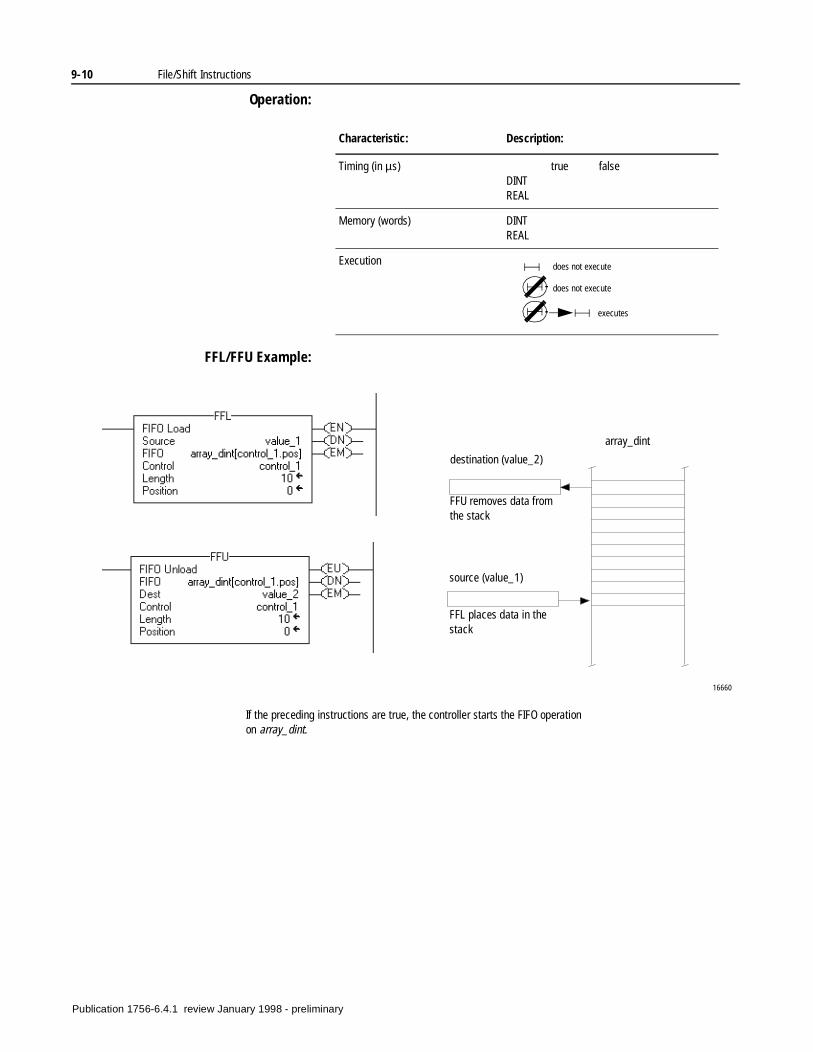
9-10 File/Shift Instructions
Operation:
FFL/FFU Example:
Characteristic: Description:
Timing (in µs) true falseDINTREAL
Memory (words) DINTREAL
Execution does not execute
does not execute
executes
If the preceding instructions are true, the controller starts the FIFO operation on array_dint.
16660
array_dint
source (value_1)
destination (value_2)
FFU removes data from the stack
FFL places data in the stack
Publication 1756-6.4.1 review January 1998 - preliminary
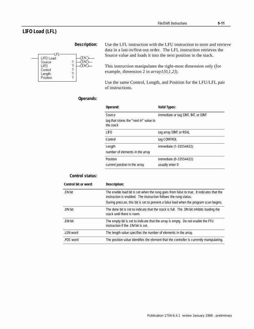
File/Shift Instructions 9-11
LIFO Load (LFL)
Description: Use the LFL instruction with the LFU instruction to store and retrieve data in a last-in/first-out order. The LFL instruction retrieves the Source value and loads it into the next position in the stack.
This instruction manipulates the right-most dimension only (for example, dimension 2 in array1[0,1,2]).
Use the same Control, Length, and Position for the LFU/LFL pair of instructions.
Operands:
Control status:
Operand: Valid Types:
Source
tag that stores the “next in” value to the stack
immediate or tag SINT, INT, or DINT
LIFO tag array DINT or REAL
Control tag CONTROL
Length
number of elements in the array
immediate (1-33554432)
Position
current position in the array
immediate (0-33554432)
usually enter 0
Control bit or word: Description:
.EN bit The enable load bit is set when the rung goes from false to true. It indicates that the instruction is enabled. The instruction follows the rung status.
During prescan, this bit is set to prevent a false load when the program scan begins.
.DN bit The done bit is set to indicate that the stack is full. The .DN bit inhibits loading the stack until there is room.
.EM bit The empty bit is set to indicate that the array is empty. Do not enable the FFU instruction if the .EM bit is set.
.LEN word The length value specifies the number of elements in the array.
.POS word The position value identifies the element that the controller is currently manipulating.
Publication 1756-6.4.1 review January 1998 - preliminary
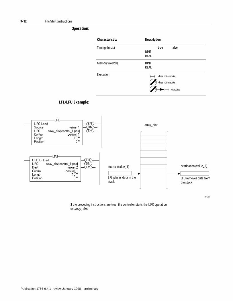
9-12 File/Shift Instructions
Operation:
LFL/LFU Example:
Characteristic: Description:
Timing (in µs) true falseDINTREAL
Memory (words) DINTREAL
Execution does not execute
does not execute
executes
If the preceding instructions are true, the controller starts the LIFO operation on array_dint.
16621
array_dint
source (value_1) destination (value_2)
LFU removes data from the stack
LFL places data in the stack
Publication 1756-6.4.1 review January 1998 - preliminary
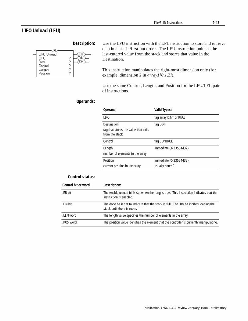
File/Shift Instructions 9-13
LIFO Unload (LFU)
Description: Use the LFU instruction with the LFL instruction to store and retrieve data in a last-in/first-out order. The LFU instruction unloads the last-entered value from the stack and stores that value in the Destination.
This instruction manipulates the right-most dimension only (for example, dimension 2 in array1[0,1,2]).
Use the same Control, Length, and Position for the LFU/LFL pair of instructions.
Operands:
Control status:
Operand: Valid Types:
LIFO tag array DINT or REAL
Destination
tag that stores the value that exits from the stack
tag DINT
Control tag CONTROL
Length
number of elements in the array
immediate (1-33554432)
Position
current position in the array
immediate (0-33554432)
usually enter 0
Control bit or word: Description:
.EU bit The enable unload bit is set when the rung is true. This instruction indicates that the instruction is enabled.
.DN bit The done bit is set to indicate that the stack is full. The .DN bit inhibits loading the stack until there is room.
.LEN word The length value specifies the number of elements in the array.
.POS word The position value identifies the element that the controller is currently manipulating.
Publication 1756-6.4.1 review January 1998 - preliminary

9-14 File/Shift Instructions
Operation:
LFL/LFU Example:
Characteristic: Description:
Timing (in µs) true falseDINTREAL
Memory (words) DINTREAL
Execution does not execute
does not execute
executes
If the preceding instructions are true, the controller starts the LIFO operation on array_dint.
16621
array_dint
source (value_1) destination (value_2)
LFU removes data from the stack
LFL places data in the stack
Publication 1756-6.4.1 review January 1998 - preliminary
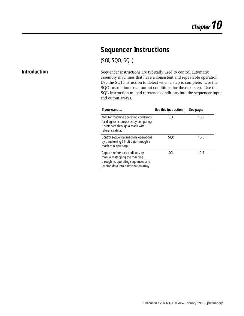
Chapter10
Sequencer Instructions(SQI, SQO, SQL)
Introduction Sequencer instructions are typically used to control automatic assembly machines that have a consistent and repeatable operation. Use the SQI instruction to detect when a step is complete. Use the SQO instruction to set output conditions for the next step. Use the SQL instruction to load reference conditions into the sequencer input and output arrays.
If you want to: Use this instruction: See page:
Monitor machine operating conditions for diagnostic purposes by comparing 32-bit data through a mask with reference data.
SQI 10-3
Control sequential machine operations by transferring 32-bit data through a mask to output tags.
SQO 10-5
Capture reference conditions by manually stepping the machine through its operating sequences and loading data into a destination array.
SQL 10-7
Publication 1756-6.4.1 review January 1998 - preliminary
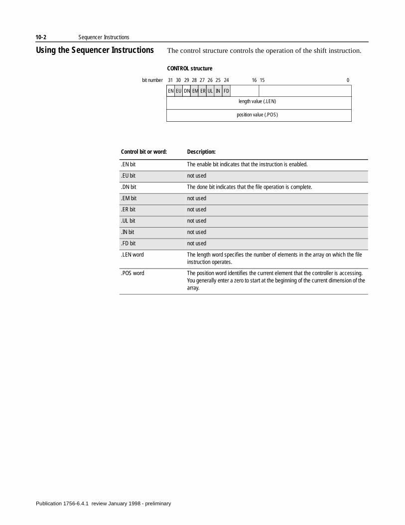
10-2 Sequencer Instructions
Using the Sequencer Instructions The control structure controls the operation of the shift instruction.
length value (.LEN)
position value (.POS)
EN EU DN EM ER UL IN FD
31 30 29 28 27 26 25 24 16 15 0bit number
CONTROL structure
Control bit or word: Description:
.EN bit The enable bit indicates that the instruction is enabled.
.EU bit not used
.DN bit The done bit indicates that the file operation is complete.
.EM bit not used
.ER bit not used
.UL bit not used
.IN bit not used
.FD bit not used
.LEN word The length word specifies the number of elements in the array on which the file instruction operates.
.POS word The position word identifies the current element that the controller is accessing. You generally enter a zero to start at the beginning of the current dimension of the array.
Publication 1756-6.4.1 review January 1998 - preliminary
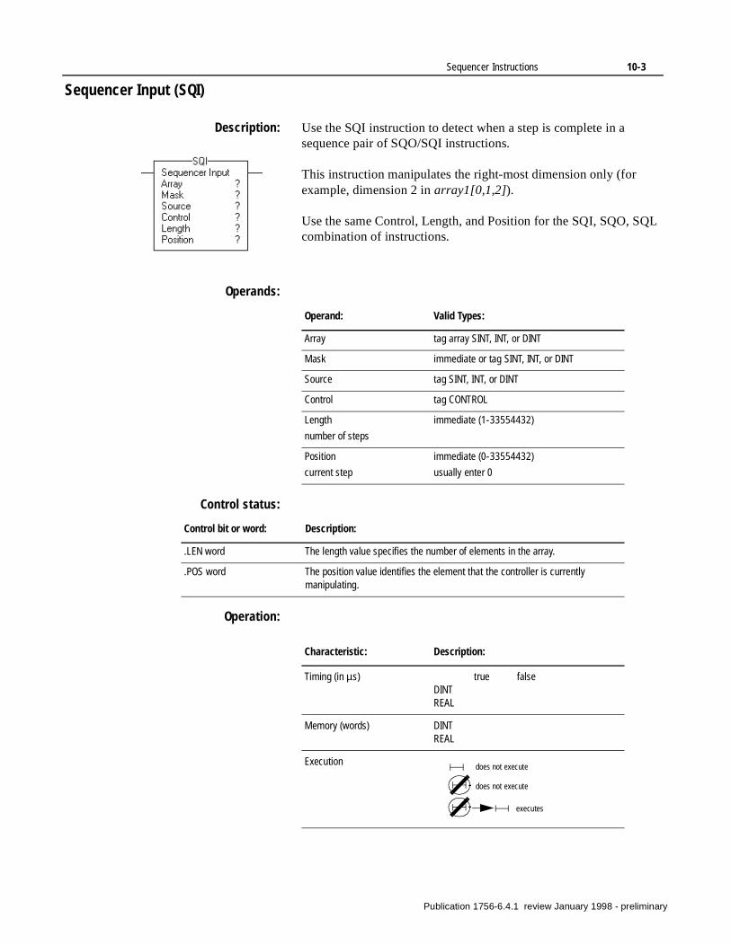
Sequencer Instructions 10-3
Sequencer Input (SQI)
Description: Use the SQI instruction to detect when a step is complete in a sequence pair of SQO/SQI instructions.
This instruction manipulates the right-most dimension only (for example, dimension 2 in array1[0,1,2]).
Use the same Control, Length, and Position for the SQI, SQO, SQL combination of instructions.
Operands:
Control status:
Operation:
Operand: Valid Types:
Array tag array SINT, INT, or DINT
Mask immediate or tag SINT, INT, or DINT
Source tag SINT, INT, or DINT
Control tag CONTROL
Length
number of steps
immediate (1-33554432)
Position
current step
immediate (0-33554432)
usually enter 0
Control bit or word: Description:
.LEN word The length value specifies the number of elements in the array.
.POS word The position value identifies the element that the controller is currently manipulating.
Characteristic: Description:
Timing (in µs) true falseDINTREAL
Memory (words) DINTREAL
Execution does not execute
does not execute
executes
Publication 1756-6.4.1 review January 1998 - preliminary
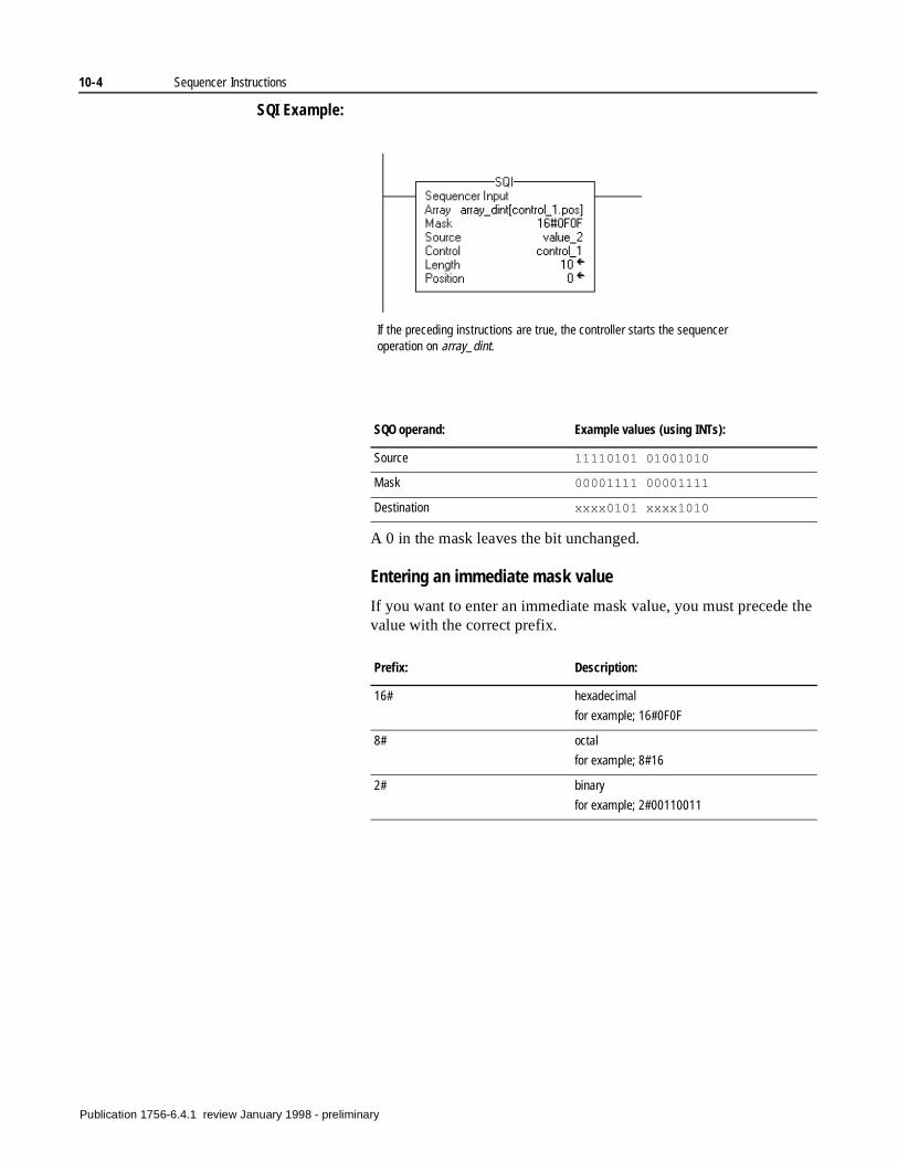
10-4 Sequencer Instructions
SQI Example:
A 0 in the mask leaves the bit unchanged.
Entering an immediate mask value
If you want to enter an immediate mask value, you must precede the value with the correct prefix.
If the preceding instructions are true, the controller starts the sequencer operation on array_dint.
SQO operand: Example values (using INTs):
Source 11110101 01001010
Mask 00001111 00001111
Destination xxxx0101 xxxx1010
Prefix: Description:
16# hexadecimal
for example; 16#0F0F
8# octal
for example; 8#16
2# binary
for example; 2#00110011
Publication 1756-6.4.1 review January 1998 - preliminary
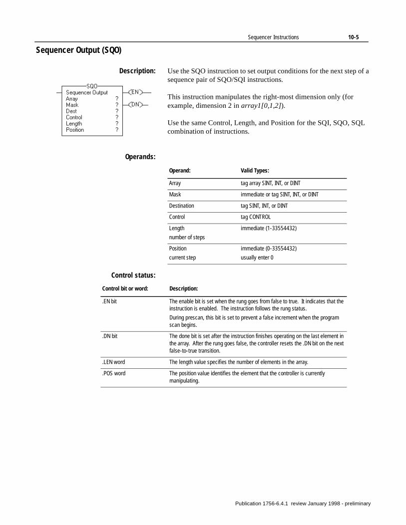
Sequencer Instructions 10-5
Sequencer Output (SQO)
Description: Use the SQO instruction to set output conditions for the next step of a sequence pair of SQO/SQI instructions.
This instruction manipulates the right-most dimension only (for example, dimension 2 in array1[0,1,2]).
Use the same Control, Length, and Position for the SQI, SQO, SQL combination of instructions.
Operands:
Control status:
Operand: Valid Types:
Array tag array SINT, INT, or DINT
Mask immediate or tag SINT, INT, or DINT
Destination tag SINT, INT, or DINT
Control tag CONTROL
Length
number of steps
immediate (1-33554432)
Position
current step
immediate (0-33554432)
usually enter 0
Control bit or word: Description:
.EN bit The enable bit is set when the rung goes from false to true. It indicates that the instruction is enabled. The instruction follows the rung status.
During prescan, this bit is set to prevent a false increment when the program scan begins.
.DN bit The done bit is set after the instruction finishes operating on the last element in the array. After the rung goes false, the controller resets the .DN bit on the next false-to-true transition.
.LEN word The length value specifies the number of elements in the array.
.POS word The position value identifies the element that the controller is currently manipulating.
Publication 1756-6.4.1 review January 1998 - preliminary
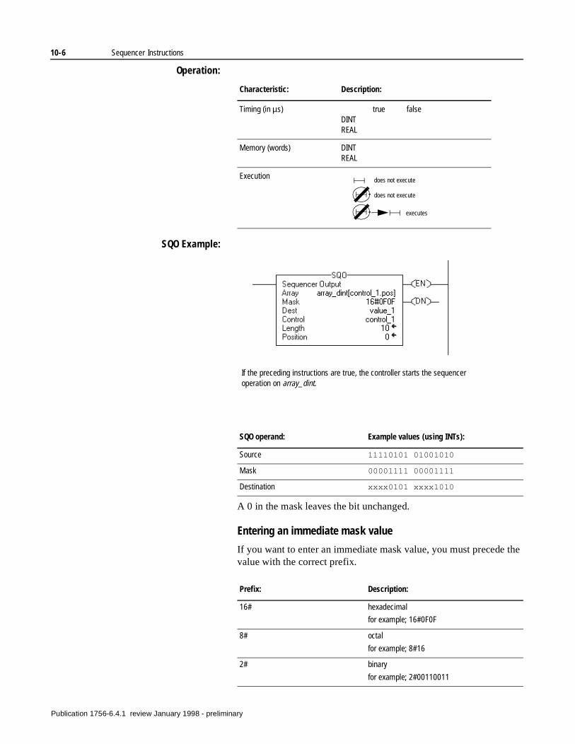
10-6 Sequencer Instructions
Operation:
SQO Example:
A 0 in the mask leaves the bit unchanged.
Entering an immediate mask value
If you want to enter an immediate mask value, you must precede the value with the correct prefix.
Characteristic: Description:
Timing (in µs) true falseDINTREAL
Memory (words) DINTREAL
Execution does not execute
does not execute
executes
If the preceding instructions are true, the controller starts the sequencer operation on array_dint.
SQO operand: Example values (using INTs):
Source 11110101 01001010
Mask 00001111 00001111
Destination xxxx0101 xxxx1010
Prefix: Description:
16# hexadecimal
for example; 16#0F0F
8# octal
for example; 8#16
2# binary
for example; 2#00110011
Publication 1756-6.4.1 review January 1998 - preliminary
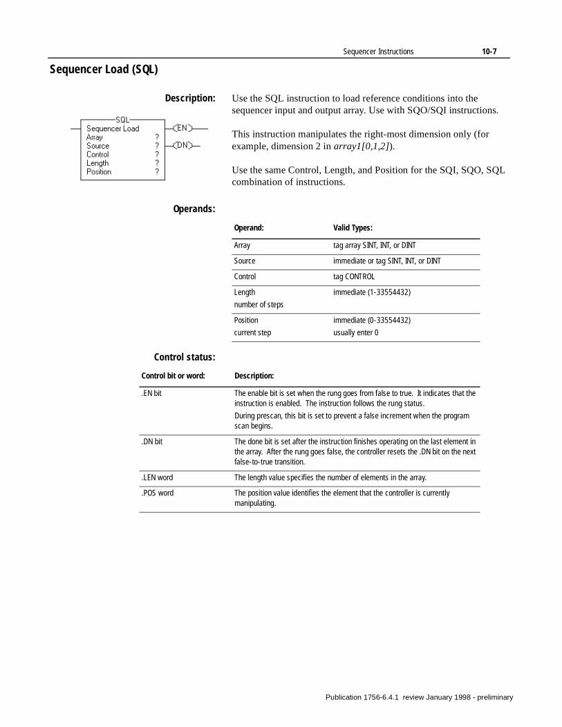
Sequencer Instructions 10-7
Sequencer Load (SQL)
Description: Use the SQL instruction to load reference conditions into the sequencer input and output array. Use with SQO/SQI instructions.
This instruction manipulates the right-most dimension only (for example, dimension 2 in array1[0,1,2]).
Use the same Control, Length, and Position for the SQI, SQO, SQL combination of instructions.
Operands:
Control status:
Operand: Valid Types:
Array tag array SINT, INT, or DINT
Source immediate or tag SINT, INT, or DINT
Control tag CONTROL
Length
number of steps
immediate (1-33554432)
Position
current step
immediate (0-33554432)
usually enter 0
Control bit or word: Description:
.EN bit The enable bit is set when the rung goes from false to true. It indicates that the instruction is enabled. The instruction follows the rung status.
During prescan, this bit is set to prevent a false increment when the program scan begins.
.DN bit The done bit is set after the instruction finishes operating on the last element in the array. After the rung goes false, the controller resets the .DN bit on the next false-to-true transition.
.LEN word The length value specifies the number of elements in the array.
.POS word The position value identifies the element that the controller is currently manipulating.
Publication 1756-6.4.1 review January 1998 - preliminary
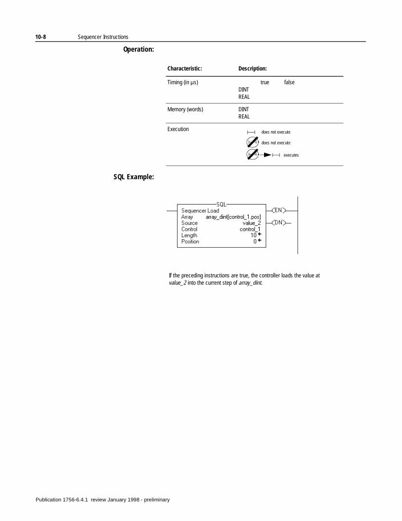
10-8 Sequencer Instructions
Operation:
SQL Example:
Characteristic: Description:
Timing (in µs) true falseDINTREAL
Memory (words) DINTREAL
Execution does not execute
does not execute
executes
If the preceding instructions are true, the controller loads the value at value_2 into the current step of array_dint.
Publication 1756-6.4.1 review January 1998 - preliminary
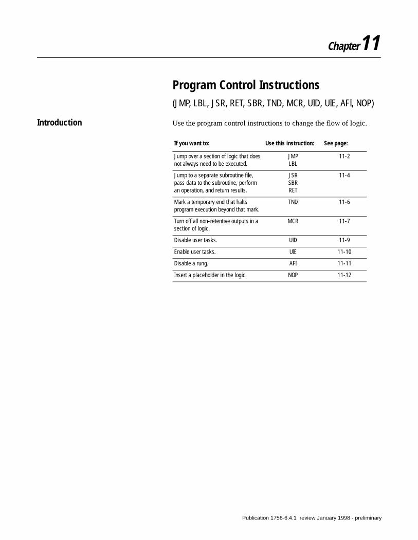
Chapter11
Program Control Instructions(JMP, LBL, JSR, RET, SBR, TND, MCR, UID, UIE, AFI, NOP)
Introduction Use the program control instructions to change the flow of logic.
If you want to: Use this instruction: See page:
Jump over a section of logic that does not always need to be executed.
JMPLBL
11-2
Jump to a separate subroutine file, pass data to the subroutine, perform an operation, and return results.
JSRSBRRET
11-4
Mark a temporary end that halts program execution beyond that mark.
TND 11-6
Turn off all non-retentive outputs in a section of logic.
MCR 11-7
Disable user tasks. UID 11-9
Enable user tasks. UIE 11-10
Disable a rung. AFI 11-11
Insert a placeholder in the logic. NOP 11-12
Publication 1756-6.4.1 review January 1998 - preliminary
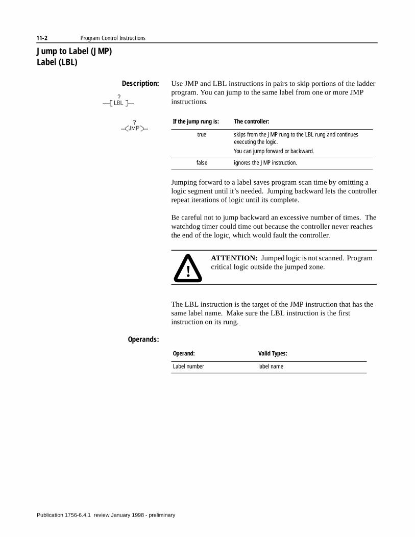
11-2 Program Control Instructions
ller
he
e
Jump to Label (JMP)Label (LBL)
Description: Use JMP and LBL instructions in pairs to skip portions of the ladder program. You can jump to the same label from one or more JMP instructions.
Jumping forward to a label saves program scan time by omitting a logic segment until it’s needed. Jumping backward lets the controrepeat iterations of logic until its complete.
Be careful not to jump backward an excessive number of times. Twatchdog timer could time out because the controller never reaches the end of the logic, which would fault the controller.
The LBL instruction is the target of the JMP instruction that has thsame label name. Make sure the LBL instruction is the first instruction on its rung.
Operands:
If the jump rung is: The controller:
true skips from the JMP rung to the LBL rung and continues executing the logic.
You can jump forward or backward.
false ignores the JMP instruction.
!ATTENTION: Jumped logic is not scanned. Programcritical logic outside the jumped zone.
Operand: Valid Types:
Label number label name
Publication 1756-6.4.1 review January 1998 - preliminary
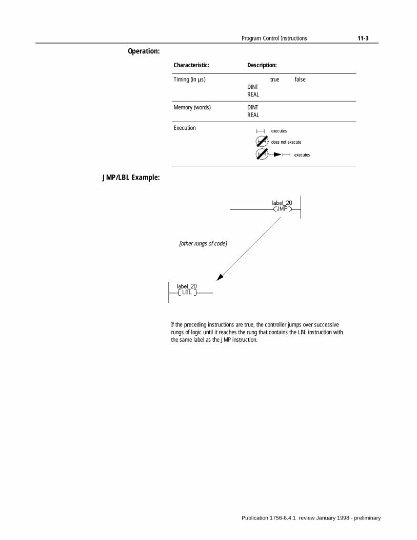
Program Control Instructions 11-3
Operation:
JMP/LBL Example:
Characteristic: Description:
Timing (in µs) true falseDINTREAL
Memory (words) DINTREAL
Execution executes
does not execute
executes
If the preceding instructions are true, the controller jumps over successive rungs of logic until it reaches the rung that contains the LBL instruction with the same label as the JMP instruction.
[other rungs of code]
Publication 1756-6.4.1 review January 1998 - preliminary
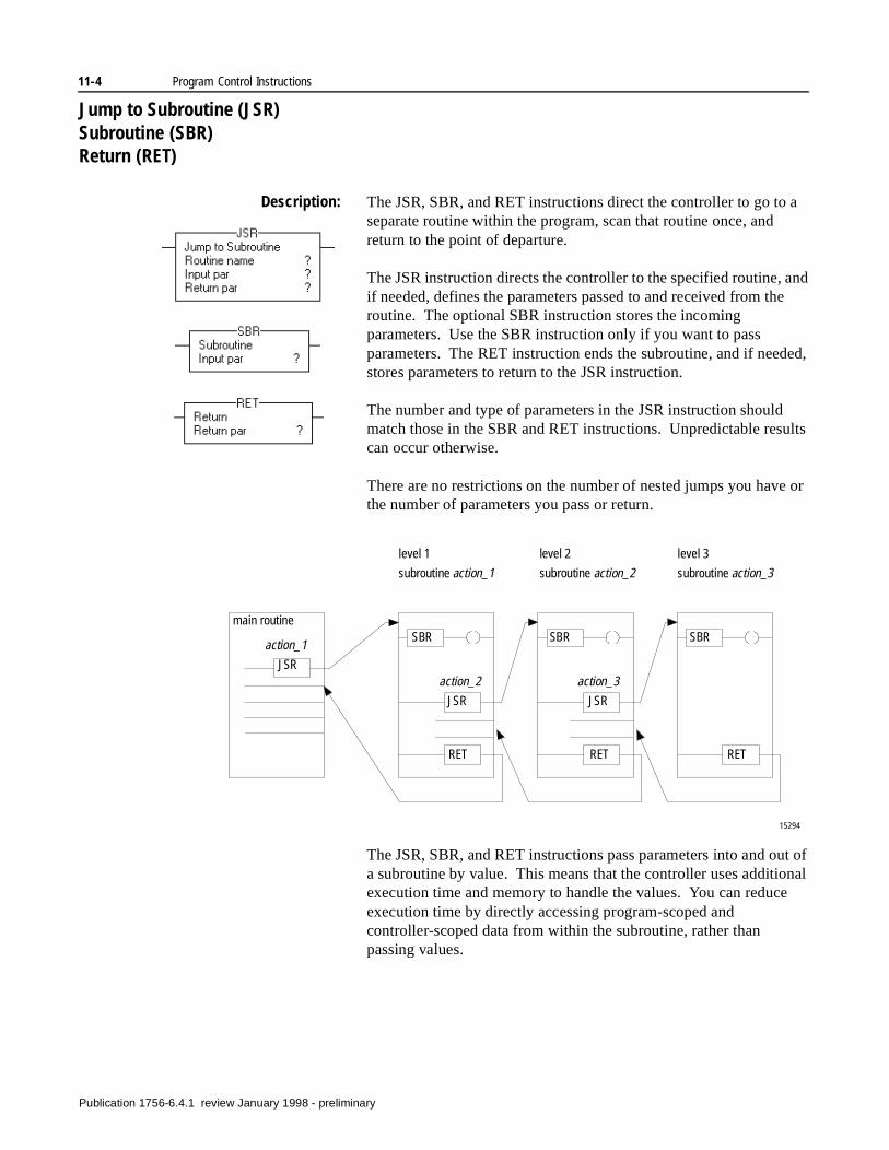
11-4 Program Control Instructions
Jump to Subroutine (JSR)Subroutine (SBR)Return (RET)
Description: The JSR, SBR, and RET instructions direct the controller to go to a separate routine within the program, scan that routine once, and return to the point of departure.
The JSR instruction directs the controller to the specified routine, and if needed, defines the parameters passed to and received from the routine. The optional SBR instruction stores the incoming parameters. Use the SBR instruction only if you want to pass parameters. The RET instruction ends the subroutine, and if needed, stores parameters to return to the JSR instruction.
The number and type of parameters in the JSR instruction should match those in the SBR and RET instructions. Unpredictable results can occur otherwise.
There are no restrictions on the number of nested jumps you have or the number of parameters you pass or return.
The JSR, SBR, and RET instructions pass parameters into and out of a subroutine by value. This means that the controller uses additional execution time and memory to handle the values. You can reduce execution time by directly accessing program-scoped and controller-scoped data from within the subroutine, rather than passing values.
15294
main routine
level 1
subroutine action_1
level 3
subroutine action_3
level 2
subroutine action_2
JSRJSR
JSR
SBRSBRSBR
RETRETRET
action_1
action_2 action_3
Publication 1756-6.4.1 review January 1998 - preliminary
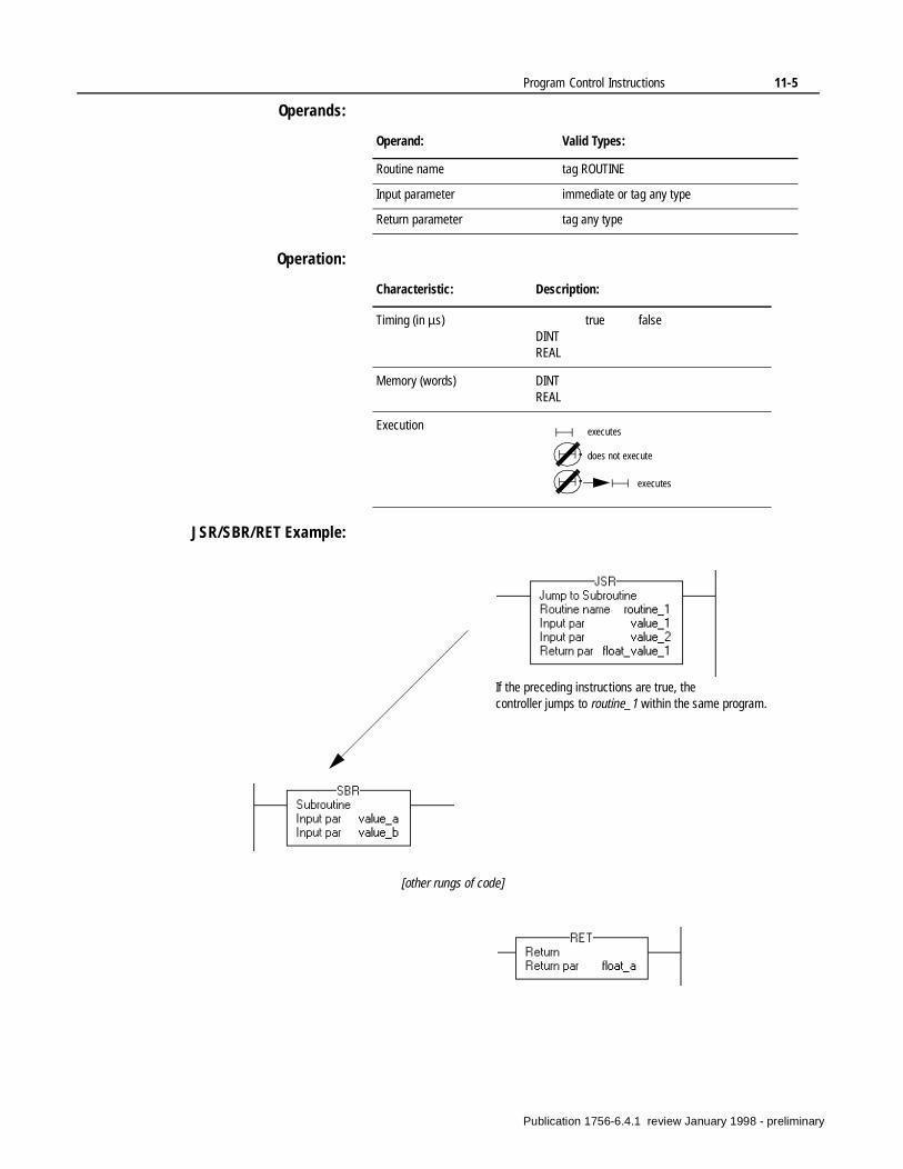
Program Control Instructions 11-5
Operands:
Operation:
JSR/SBR/RET Example:
Operand: Valid Types:
Routine name tag ROUTINE
Input parameter immediate or tag any type
Return parameter tag any type
Characteristic: Description:
Timing (in µs) true falseDINTREAL
Memory (words) DINTREAL
Execution executes
does not execute
executes
If the preceding instructions are true, the controller jumps to routine_1 within the same program.
[other rungs of code]
Publication 1756-6.4.1 review January 1998 - preliminary
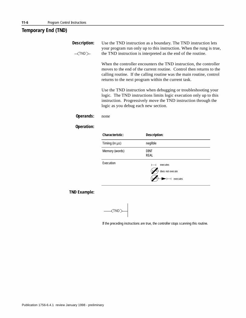
11-6 Program Control Instructions
Temporary End (TND)
Description: Use the TND instruction as a boundary. The TND instruction lets your program run only up to this instruction. When the rung is true, the TND instruction is interpreted as the end of the routine.
When the controller encounters the TND instruction, the controller moves to the end of the current routine. Control then returns to the calling routine. If the calling routine was the main routine, control returns to the next program within the current task.
Use the TND instruction when debugging or troubleshooting your logic. The TND instructions limits logic execution only up to this instruction. Progressively move the TND instruction through the logic as you debug each new section.
Operands: none
Operation:
TND Example:
Characteristic: Description:
Timing (in µs) neglible
Memory (words) DINTREAL
Execution executes
does not execute
executes
If the preceding instructions are true, the controller stops scanning this routine.
Publication 1756-6.4.1 review January 1998 - preliminary
Program Control Instructions 11-7
.
to
t
d
er-
Master Reset Control (MCR)
Description: Use the MCR instructions in pairs to create program zones that turn off all the non-retentive outputs in the zone. The controller still scans rungs within an MCR zone, but scan time is reduced because all the rungs in the zone are false. Non-retentive outputs are reset when the rung goes false.
MCR zones let you enable or inhibit segments of logic, such as for recipe applications.
When you program an MCR zone, note that:
• You must end the zone with an unconditional MCR instruction
• You cannot nest one MCR zone within another.
• Do not jump into an MCR zone. If the zone is false, jumping inthe zone activates the zone.
• If an MCR zone continues to the end of the routine, you do nohave to program an MCR instruction to end the zone.
Important: The MCR instruction is not a substitute for a hard-wiremaster control relay that provides emergency-stop capability. Youshould still install a hard-wired master control relay to provide emgency I/O power shutdown.
Operands: none
If the MCR rung that starts the zone is:
The controller:
true Executes the rungs in the MCR zone based on each rung’s individual conditions (as if the MCR zone did not exist).
false Resets all non-retentive output instructions in the MCR zone, regardless of each rung’s individual conditions.
!ATTENTION: Do not overlap or nest MCR zones. Each MCR zone must be separate and complete. If they overlap or nest, unpredictable machine operation could occur with possible damage to equipment or injury to personnel.
If you start instructions such as timers or counters in an MCR zone, instruction execution stops when the zone is disabled. Program critical operations outside the zone.
Publication 1756-6.4.1 review January 1998 - preliminary
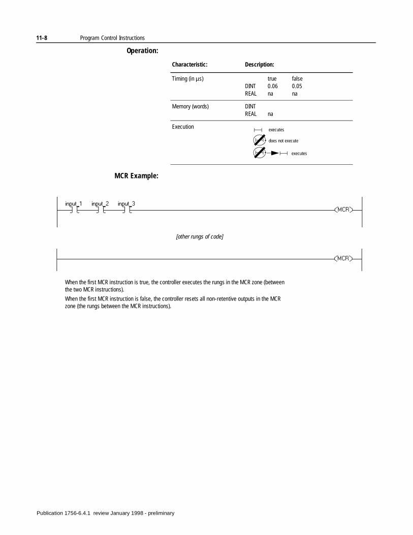
11-8 Program Control Instructions
Operation:
MCR Example:
Characteristic: Description:
Timing (in µs) true falseDINT 0.06 0.05REAL na na
Memory (words) DINTREAL na
Execution executes
does not execute
executes
When the first MCR instruction is true, the controller executes the rungs in the MCR zone (between the two MCR instructions).
When the first MCR instruction is false, the controller resets all non-retentive outputs in the MCR zone (the rungs between the MCR instructions).
[other rungs of code]
Publication 1756-6.4.1 review January 1998 - preliminary
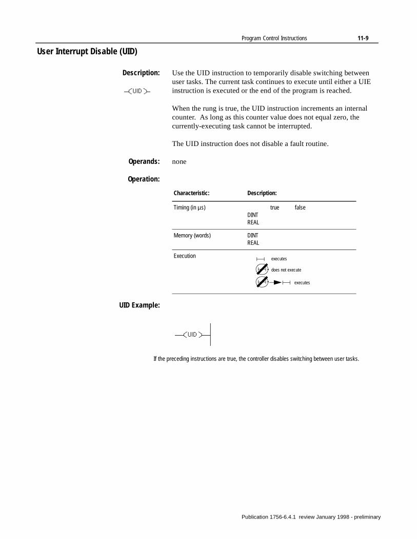
Program Control Instructions 11-9
User Interrupt Disable (UID)
Description: Use the UID instruction to temporarily disable switching between user tasks. The current task continues to execute until either a UIE instruction is executed or the end of the program is reached.
When the rung is true, the UID instruction increments an internal counter. As long as this counter value does not equal zero, the currently-executing task cannot be interrupted.
The UID instruction does not disable a fault routine.
Operands: none
Operation:
UID Example:
Characteristic: Description:
Timing (in µs) true falseDINTREAL
Memory (words) DINTREAL
Execution executes
does not execute
executes
If the preceding instructions are true, the controller disables switching between user tasks.
Publication 1756-6.4.1 review January 1998 - preliminary
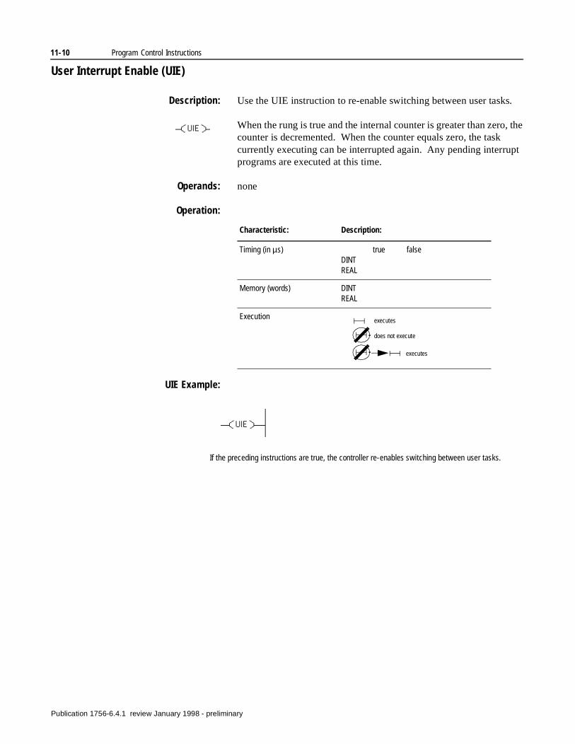
11-10 Program Control Instructions
User Interrupt Enable (UIE)
Description: Use the UIE instruction to re-enable switching between user tasks.
When the rung is true and the internal counter is greater than zero, the counter is decremented. When the counter equals zero, the task currently executing can be interrupted again. Any pending interrupt programs are executed at this time.
Operands: none
Operation:
UIE Example:
Characteristic: Description:
Timing (in µs) true falseDINTREAL
Memory (words) DINTREAL
Execution executes
does not execute
executes
If the preceding instructions are true, the controller re-enables switching between user tasks.
Publication 1756-6.4.1 review January 1998 - preliminary
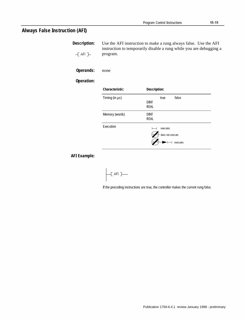
Program Control Instructions 11-11
Always False Instruction (AFI)
Description: Use the AFI instruction to make a rung always false. Use the AFI instruction to temporarily disable a rung while you are debugging a program.
Operands: none
Operation:
AFI Example:
Characteristic: Description:
Timing (in µs) true falseDINTREAL
Memory (words) DINTREAL
Execution executes
does not execute
executes
If the preceding instructions are true, the controller makes the current rung false.
Publication 1756-6.4.1 review January 1998 - preliminary
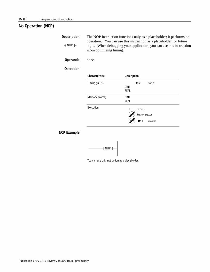
11-12 Program Control Instructions
No Operation (NOP)
Description: The NOP instruction functions only as a placeholder; it performs no operation. You can use this instruction as a placeholder for future logic. When debugging your application, you can use this instruction when optimizing timing.
Operands: none
Operation:
NOP Example:
Characteristic: Description:
Timing (in µs) true falseDINTREAL
Memory (words) DINTREAL
Execution executes
does not execute
executes
You can use this instruction as a placeholder.
Publication 1756-6.4.1 review January 1998 - preliminary
Chapter12
For/Break Instructions(FOR, BRK)
Introduction Use the FOR instruction to repeatedly call a subroutine. Use the BRK instruction to interrupt the execution of the subroutine.
If you want to: Use this instruction: See page:
Repeatedly execute a routine. FOR
Terminate the repeated execution of a routine.
BRK
Publication 1756-6.4.1 review January 1998 - preliminary
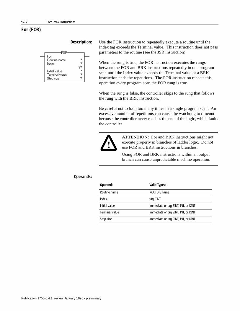
12-2 For/Break Instructions
For (FOR)
Description: Use the FOR instruction to repeatedly execute a routine until the Index tag exceeds the Terminal value. This instruction does not pass parameters to the routine (see the JSR instruction).
When the rung is true, the FOR instruction executes the rungs between the FOR and BRK instructions repeatedly in one program scan until the Index value exceeds the Terminal value or a BRK instruction ends the repetitions. The FOR instruction repeats this operation every program scan the FOR rung is true.
When the rung is false, the controller skips to the rung that follows the rung with the BRK instruction.
Be careful not to loop too many times in a single program scan. An excessive number of repetitions can cause the watchdog to timeout because the controller never reaches the end of the logic, which faults the controller.
Operands:
!ATTENTION: For and BRK instructions might not execute properly in branches of ladder logic. Do not use FOR and BRK instructions in branches.
Using FOR and BRK instructions within an output branch can cause unpredictable machine operation.
Operand: Valid Types:
Routine name ROUTINE name
Index tag DINT
Initial value immediate or tag SINT, INT, or DINT
Terminal value immediate or tag SINT, INT, or DINT
Step size immediate or tag SINT, INT, or DINT
Publication 1756-6.4.1 review January 1998 - preliminary
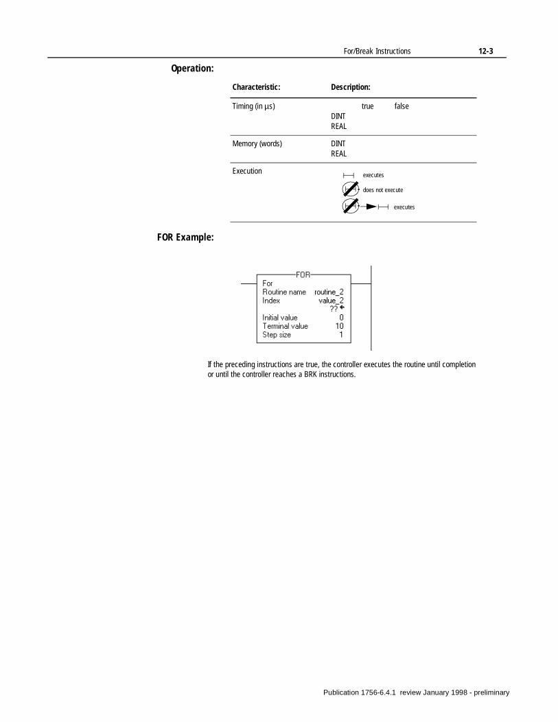
For/Break Instructions 12-3
Operation:
FOR Example:
Characteristic: Description:
Timing (in µs) true falseDINTREAL
Memory (words) DINTREAL
Execution executes
does not execute
executes
If the preceding instructions are true, the controller executes the routine until completion or until the controller reaches a BRK instructions.
Publication 1756-6.4.1 review January 1998 - preliminary
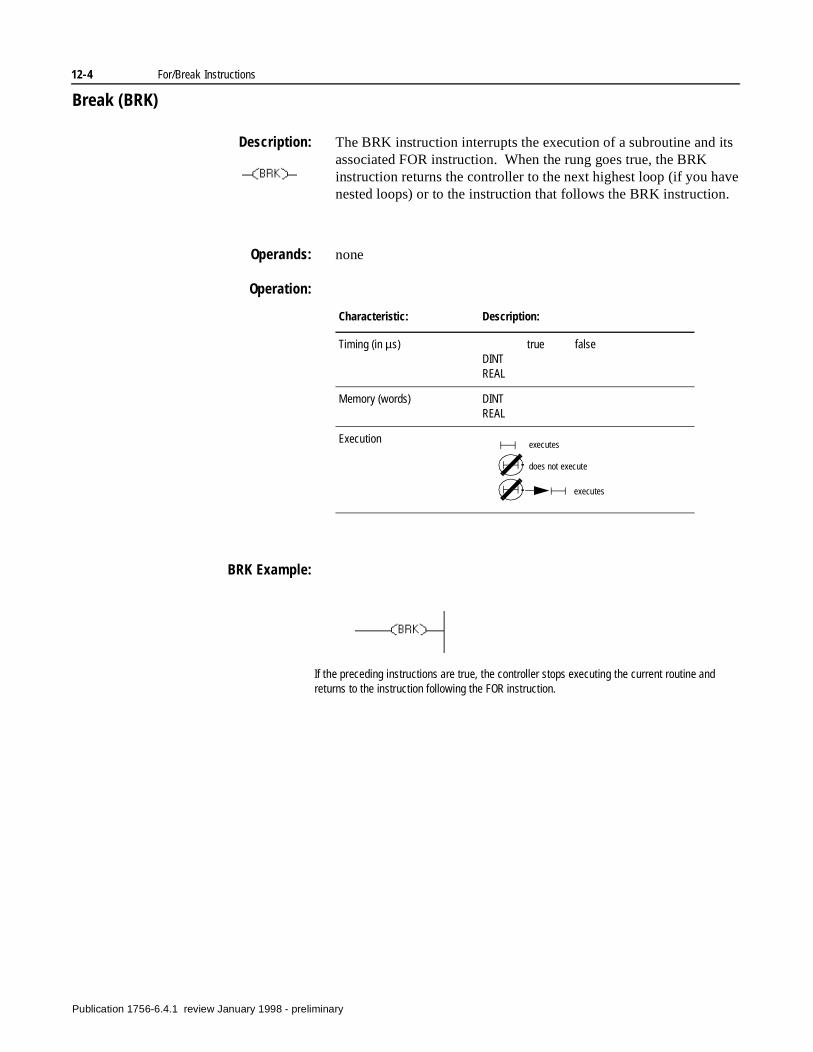
12-4 For/Break Instructions
Break (BRK)
Description: The BRK instruction interrupts the execution of a subroutine and its associated FOR instruction. When the rung goes true, the BRK instruction returns the controller to the next highest loop (if you have nested loops) or to the instruction that follows the BRK instruction.
Operands: none
Operation:
BRK Example:
Characteristic: Description:
Timing (in µs) true falseDINTREAL
Memory (words) DINTREAL
Execution executes
does not execute
executes
If the preceding instructions are true, the controller stops executing the current routine and returns to the instruction following the FOR instruction.
Publication 1756-6.4.1 review January 1998 - preliminary
Chapter13
Special Instructions(FBC, DDT, DTR, PID)
Introduction The special instructions perform application-specific operations.
If you want to: Use this instruction: See page:
Compare I/O data against a known, good reference and record any mismatches.
FBC 13-3
Compare I/O data against a known, good reference, record any mismatches, and update the reference to match the source.
DDT 13-6
Pass the source data through a mask and compare the result to reference data. Then write the source into the reference for the next comparison.
DTR 13-9
Control a PID loop with inputs from an analog input module and an output to an analog output module.
PID 13-17
Publication 1756-6.4.1 review January 1998 - preliminary
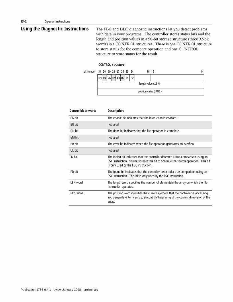
13-2 Special Instructions
Using the Diagnostic Instructions The FBC and DDT diagnostic instructions let you detect problems with data in your programs. The controller stores status bits and the length and position values in a 96-bit storage structure (three 32-bit words) in a CONTROL structures. There is one CONTROL structure to store status for the compare operation and one CONTROL structure to store status for the result.
CONTROL structure
length value (.LEN)
position value (.POS)
EN EU DN EM ER UL IN FD
31 30 29 28 27 26 25 24 16 15 0bit number
Control bit or word: Description:
.EN bit The enable bit indicates that the instruction is enabled.
.EU bit not used
.DN bit The done bit indicates that the file operation is complete.
.EM bit not used
.ER bit The error bit indicates when the file operation generates an overflow.
.UL bit not used
.IN bit The inhibit bit indicates that the controller detected a true comparison using an FSC instruction. You must reset this bit to continue the search operation. This bit is only used by the FSC instruction.
.FD bit The found bit indicates that the controller detected a true comparison using an FSC instruction. This bit is only used by the FSC instruction.
.LEN word The length word specifies the number of elementsin the array on which the file instruction operates.
.POS word The position word identifies the current element that the controller is accessing. You generally enter a zero to start at the beginning of the current dimension of the array.
Publication 1756-6.4.1 review January 1998 - preliminary
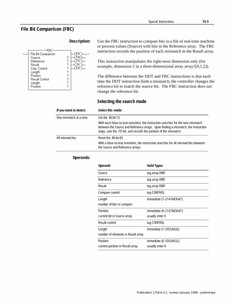
Special Instructions 13-3
File Bit Comparison (FBC)
Description: Use the FBC instruction to compare bits in a file of real-time machine or process values (Source) with bits in the Reference array. The FBC instruction records the position of each mismatch in the Result array.
This instruction manipulates the right-most dimension only (for example, dimension 2 in a three-dimensional array array1[0,1,2]).
The difference between the DDT and FBC instructions is that each time the DDT instruction finds a mismatch, the controller changes the reference bit to match the source bit. The FBC instruction does not change the reference bit.
Selecting the search mode
Operands:
If you want to detect: Select this mode:
One mismatch at a time Set the .IN bit (1)
With each false-to-true transition, the instruction searches for the next mismatch between the Source and Reference arrays. Upon finding a mismatch, the instruction stops, sets the .FD bit, and records the position of the mismatch.
All mismatches Reset the .IN bit (0)
With a false-to-true transition, the instruction searches for all mismatches between the Source and Reference arrays.
Operand: Valid Types:
Source tag array DINT
Reference tag array DINT
Result tag array DINT
Compare control tag CONTROL
Length
number of bits to compare
immediate (1-2147483647)
Position
current bit in Source array
immediate (0-2147483647)
usually enter 0
Result control tag CONTROL
Length
number of elements in Result array
immediate (1-33554432)
Position
current position in Result array
immediate (0-33554432)
usually enter 0
Publication 1756-6.4.1 review January 1998 - preliminary
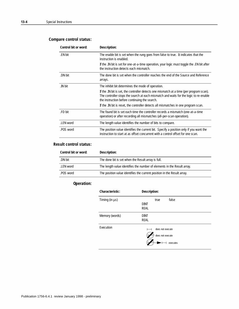
13-4 Special Instructions
Compare control status:
Result control status:
Operation:
Control bit or word: Description:
.EN bit The enable bit is set when the rung goes from false to true. It indicates that the instruction is enabled.
If the .IN bit is set for one-at-a-time operation, your logic must toggle the .EN bit after the instruction detects each mismatch.
.DN bit The done bit is set when the controller reaches the end of the Source and Reference arrays.
.IN bit The inhibit bit determines the mode of operation.
If the .IN bit is set, the controller detects one mismatch at a time (per program scan). The controller stops the search at each mismatch and waits for the logic to re-enable the instruction before continuing the search.
If the .IN bit is reset, the controller detects all mismatches in one program scan.
.FD bit The found bit is set each time the controller records a mismatch (one-at-a-time operation) or after recording all mismatches (all-per-scan operation).
.LEN word The length value identifies the number of bits to compare.
.POS word The position value identifies the current bit. Specify a position only if you want the instruction to start at as offset concurrent with a control offset for one scan.
Control bit or word: Description:
.DN bit The done bit is set when the Result array is full.
.LEN word The length value identifies the number of elements in the Result array.
.POS word The position value identifies the current position in the Result array.
Characteristic: Description:
Timing (in µs) true falseDINTREAL
Memory (words) DINTREAL
Execution does not execute
does not execute
executes
Publication 1756-6.4.1 review January 1998 - preliminary

Special Instructions 13-5
FBC Example:
If the preceding instructions are true, the controller compares the source array_dint_1 to the reference array_dint_2 and stores the locations of any mismatches in the result array_dint_3.
source
array_dint_115 14 13 12 11 10 9 8 7 6 5 4 3 2 1 0
16657
15 14 13 12 11 10 9 8 7 6 5 4 3 2 1 0
1 1 1 1 0 0 0 0 1 1 1
1 0 1 1 0 0 0 1 1 1 1
reference
array_dint_2
result
array_dint_3
3
9
Publication 1756-6.4.1 review January 1998 - preliminary
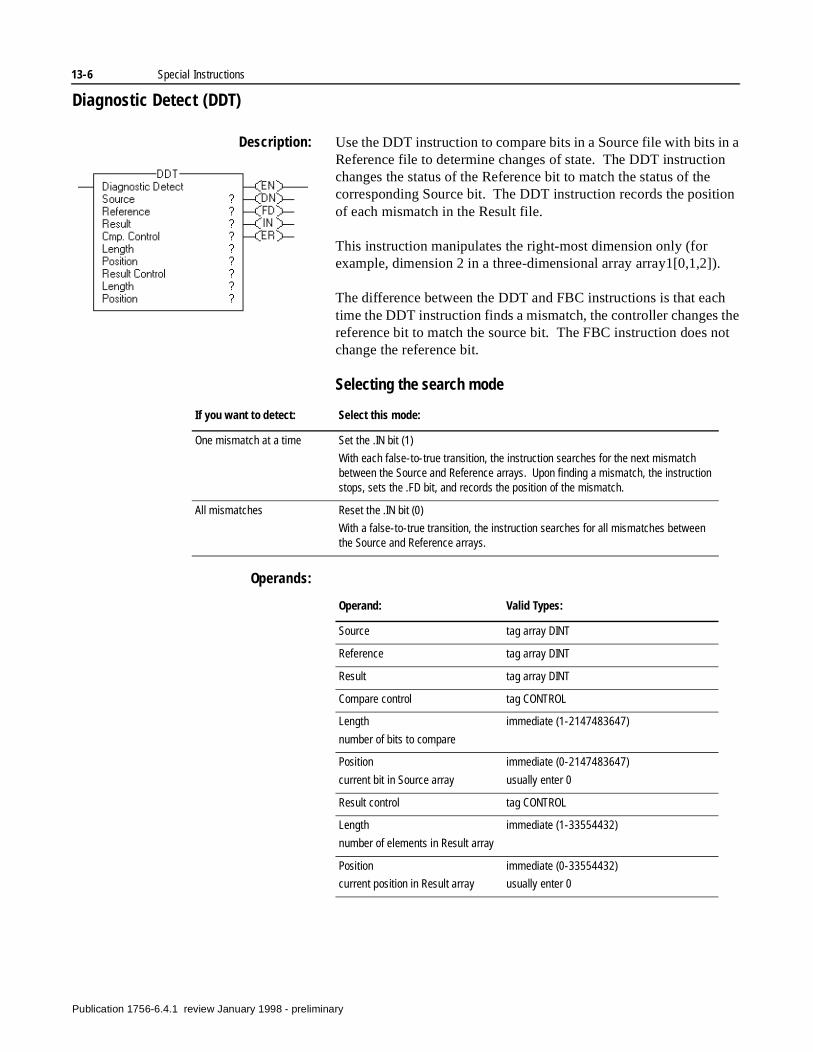
13-6 Special Instructions
Diagnostic Detect (DDT)
Description: Use the DDT instruction to compare bits in a Source file with bits in a Reference file to determine changes of state. The DDT instruction changes the status of the Reference bit to match the status of the corresponding Source bit. The DDT instruction records the position of each mismatch in the Result file.
This instruction manipulates the right-most dimension only (for example, dimension 2 in a three-dimensional array array1[0,1,2]).
The difference between the DDT and FBC instructions is that each time the DDT instruction finds a mismatch, the controller changes the reference bit to match the source bit. The FBC instruction does not change the reference bit.
Selecting the search mode
Operands:
If you want to detect: Select this mode:
One mismatch at a time Set the .IN bit (1)
With each false-to-true transition, the instruction searches for the next mismatch between the Source and Reference arrays. Upon finding a mismatch, the instruction stops, sets the .FD bit, and records the position of the mismatch.
All mismatches Reset the .IN bit (0)
With a false-to-true transition, the instruction searches for all mismatches between the Source and Reference arrays.
Operand: Valid Types:
Source tag array DINT
Reference tag array DINT
Result tag array DINT
Compare control tag CONTROL
Length
number of bits to compare
immediate (1-2147483647)
Position
current bit in Source array
immediate (0-2147483647)
usually enter 0
Result control tag CONTROL
Length
number of elements in Result array
immediate (1-33554432)
Position
current position in Result array
immediate (0-33554432)
usually enter 0
Publication 1756-6.4.1 review January 1998 - preliminary
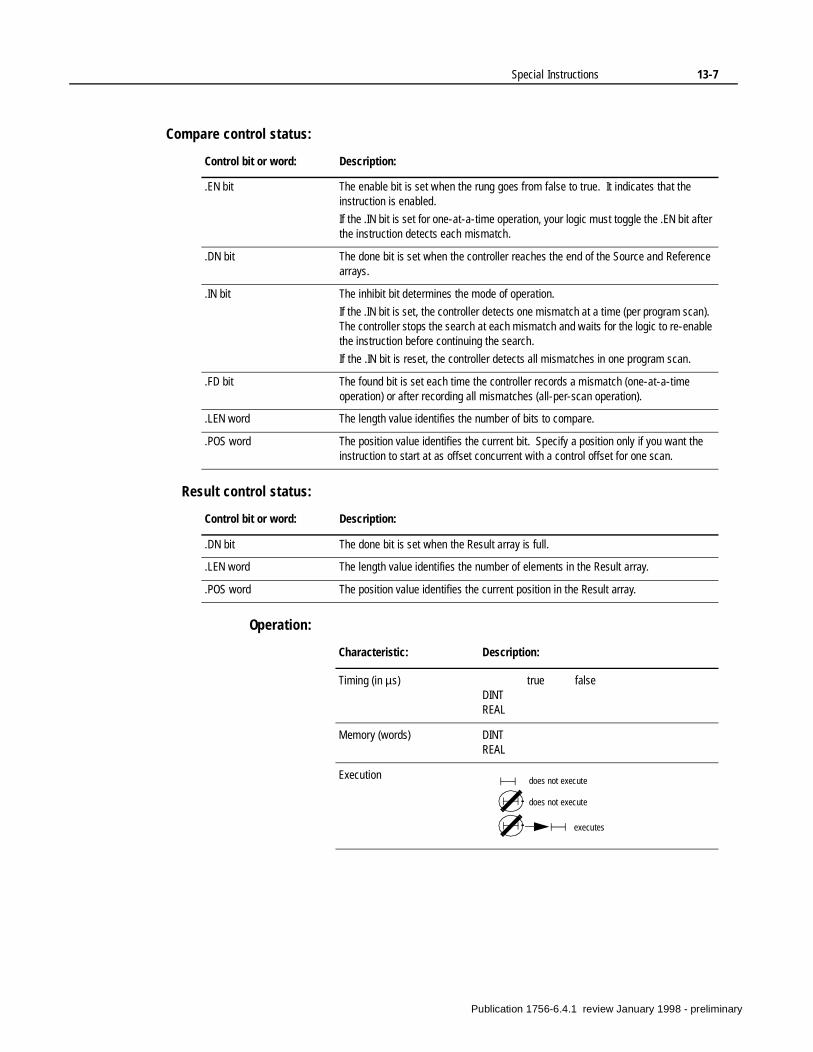
Special Instructions 13-7
Compare control status:
Result control status:
Operation:
Control bit or word: Description:
.EN bit The enable bit is set when the rung goes from false to true. It indicates that the instruction is enabled.
If the .IN bit is set for one-at-a-time operation, your logic must toggle the .EN bit after the instruction detects each mismatch.
.DN bit The done bit is set when the controller reaches the end of the Source and Reference arrays.
.IN bit The inhibit bit determines the mode of operation.
If the .IN bit is set, the controller detects one mismatch at a time (per program scan). The controller stops the search at each mismatch and waits for the logic to re-enable the instruction before continuing the search.
If the .IN bit is reset, the controller detects all mismatches in one program scan.
.FD bit The found bit is set each time the controller records a mismatch (one-at-a-time operation) or after recording all mismatches (all-per-scan operation).
.LEN word The length value identifies the number of bits to compare.
.POS word The position value identifies the current bit. Specify a position only if you want the instruction to start at as offset concurrent with a control offset for one scan.
Control bit or word: Description:
.DN bit The done bit is set when the Result array is full.
.LEN word The length value identifies the number of elements in the Result array.
.POS word The position value identifies the current position in the Result array.
Characteristic: Description:
Timing (in µs) true falseDINTREAL
Memory (words) DINTREAL
Execution does not execute
does not execute
executes
Publication 1756-6.4.1 review January 1998 - preliminary
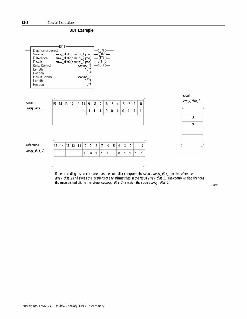
13-8 Special Instructions
DDT Example:
If the preceding instructions are true, the controller compares the source array_dint_1 to the reference array_dint_2 and stores the locations of any mismatches in the result array_dint_3. The controller also changes the mismatched bits in the reference array_dint_2 to match the source array_dint_1.
source
array_dint_115 14 13 12 11 10 9 8 7 6 5 4 3 2 1 0
16657
15 14 13 12 11 10 9 8 7 6 5 4 3 2 1 0
1 1 1 1 0 0 0 0 1 1 1
1 0 1 1 0 0 0 1 1 1 1
reference
array_dint_2
result
array_dint_3
3
9
Publication 1756-6.4.1 review January 1998 - preliminary
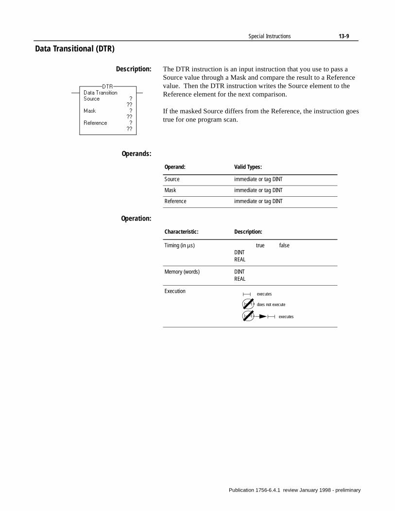
Special Instructions 13-9
Data Transitional (DTR)
Description: The DTR instruction is an input instruction that you use to pass a Source value through a Mask and compare the result to a Reference value. Then the DTR instruction writes the Source element to the Reference element for the next comparison.
If the masked Source differs from the Reference, the instruction goes true for one program scan.
Operands:
Operation:
Operand: Valid Types:
Source immediate or tag DINT
Mask immediate or tag DINT
Reference immediate or tag DINT
Characteristic: Description:
Timing (in µs) true falseDINTREAL
Memory (words) DINTREAL
Execution executes
does not execute
executes
Publication 1756-6.4.1 review January 1998 - preliminary
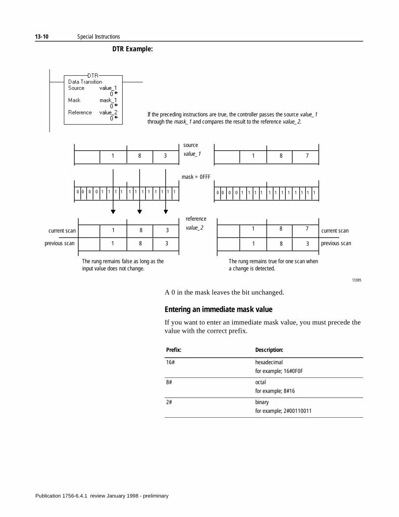
13-10 Special Instructions
DTR Example:
A 0 in the mask leaves the bit unchanged.
Entering an immediate mask value
If you want to enter an immediate mask value, you must precede the value with the correct prefix.
If the preceding instructions are true, the controller passes the source value_1 through the mask_1 and compares the result to the reference value_2.
13385
The rung remains false as long as the input value does not change.
The rung remains true for one scan when a change is detected.
0 0 0 0 1 1 1 1 1 1 1 1 1 1 1 1 0 0 0 0 1 1 1 1 1 1 1 1 1 1 1 1
1 8 3 1 8 7
mask = 0FFF
1 8 7
source
value_1
reference
value_2
1 8 3
1 8 3
1 8 3
current scan
previous scan previous scan
current scan
Prefix: Description:
16# hexadecimal
for example; 16#0F0F
8# octal
for example; 8#16
2# binary
for example; 2#00110011
Publication 1756-6.4.1 review January 1998 - preliminary
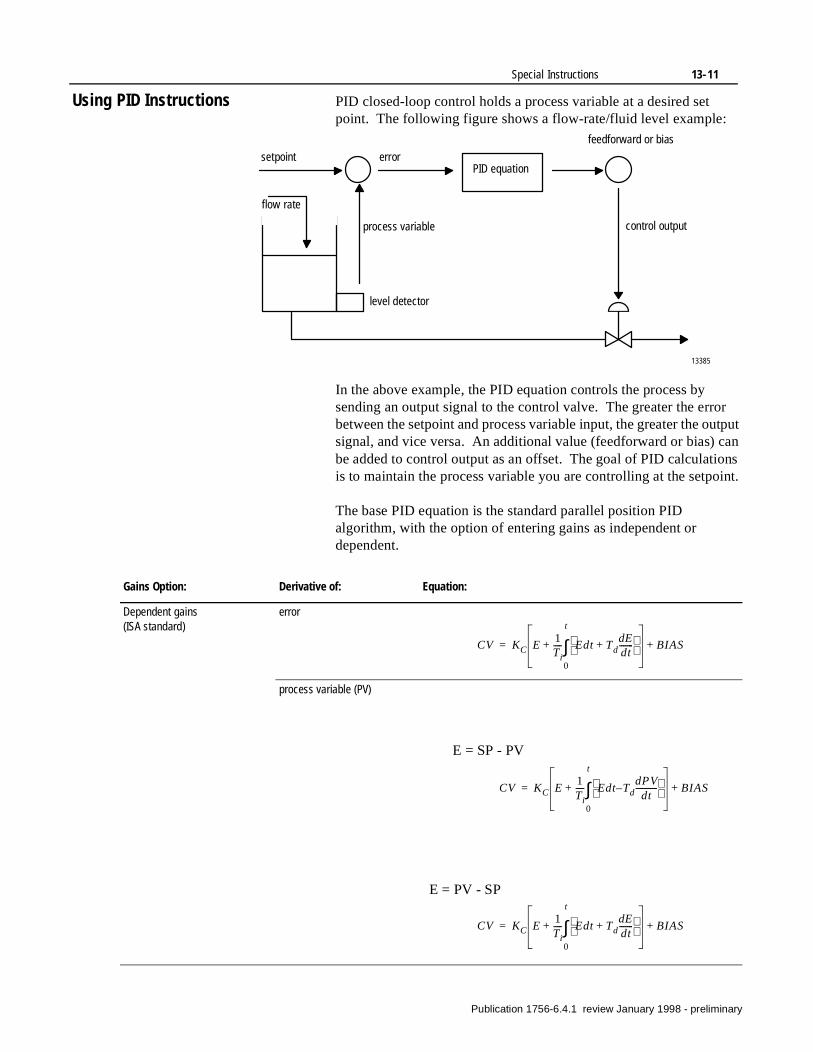
Special Instructions 13-11
Using PID Instructions PID closed-loop control holds a process variable at a desired set point. The following figure shows a flow-rate/fluid level example:
In the above example, the PID equation controls the process by sending an output signal to the control valve. The greater the error between the setpoint and process variable input, the greater the output signal, and vice versa. An additional value (feedforward or bias) can be added to control output as an offset. The goal of PID calculations is to maintain the process variable you are controlling at the setpoint.
The base PID equation is the standard parallel position PID algorithm, with the option of entering gains as independent or dependent.
13385
setpoint
flow rate
errorPID equation
feedforward or bias
control outputprocess variable
level detector
Gains Option: Derivative of: Equation:
Dependent gains(ISA standard)
error
process variable (PV)
CV KC E1Ti---- Edt Td
dEdt-------+
0
t
∫+ BIAS+=
CV KC E1Ti---- Edt Td–
dPVdt
-----------
0
t
∫+ BIAS+=
E = SP - PV
CV KC E1Ti---- Edt Td
dEdt-------+
0
t
∫+ BIAS+=
E = PV - SP
Publication 1756-6.4.1 review January 1998 - preliminary
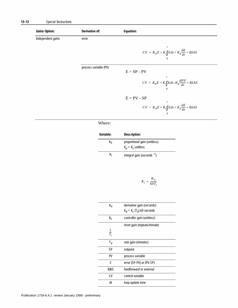
13-12 Special Instructions
Where:
Independent gains error
process variable (PV)
Gains Option: Derivative of: Equation:
CV KPE Ki+ Edt KddEdt-------+
0
t
∫ BIAS+=
CV KPE Ki+ Edt Kd–dPVdt
-----------
0
t
∫ BIAS+=
E = SP - PV
CV KPE Ki+ Edt KddEdt-------+
0
t
∫ BIAS+=
E = PV - SP
Variable: Description:
KP proportional gain (unitless)
Kp = Kc unitless
Ki integral gain (seconds -1)
Kd derivative gain (seconds)
Kd = Kc (Td) 60 seconds
KC controller gain (unitless)
reset gain (repeats/minute)
Td rate gain (minutes)
SP setpoint
PV process variable
E error (SP-PV) or (PV-SP)
BIAS feedforward or external
CV control variable
dt loop update time
Ki
KC
60Ti-----------=
1Ti----
Publication 1756-6.4.1 review January 1998 - preliminary
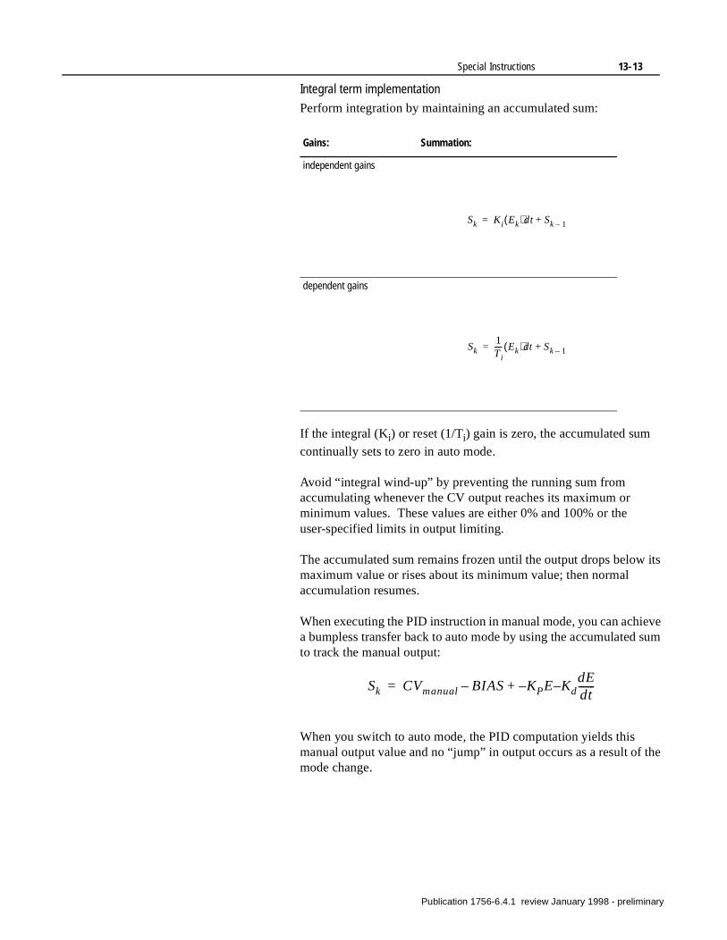
Special Instructions 13-13
its
eve sum
the
Integral term implementation
Perform integration by maintaining an accumulated sum:
If the integral (Ki) or reset (1/Ti) gain is zero, the accumulated sum
continually sets to zero in auto mode.
Avoid “integral wind-up” by preventing the running sum from accumulating whenever the CV output reaches its maximum or minimum values. These values are either 0% and 100% or the user-specified limits in output limiting.
The accumulated sum remains frozen until the output drops belowmaximum value or rises about its minimum value; then normal accumulation resumes.
When executing the PID instruction in manual mode, you can achia bumpless transfer back to auto mode by using the accumulatedto track the manual output:
When you switch to auto mode, the PID computation yields this manual output value and no “jump” in output occurs as a result of mode change.
Gains: Summation:
independent gains
dependent gains
Sk Ki Ek( )dt Sk 1–+=
Sk1Ti---- Ek( )dt Sk 1–+=
Sk CVmanual BIAS– KPE– Kd–dEdt-------+=
Publication 1756-6.4.1 review January 1998 - preliminary
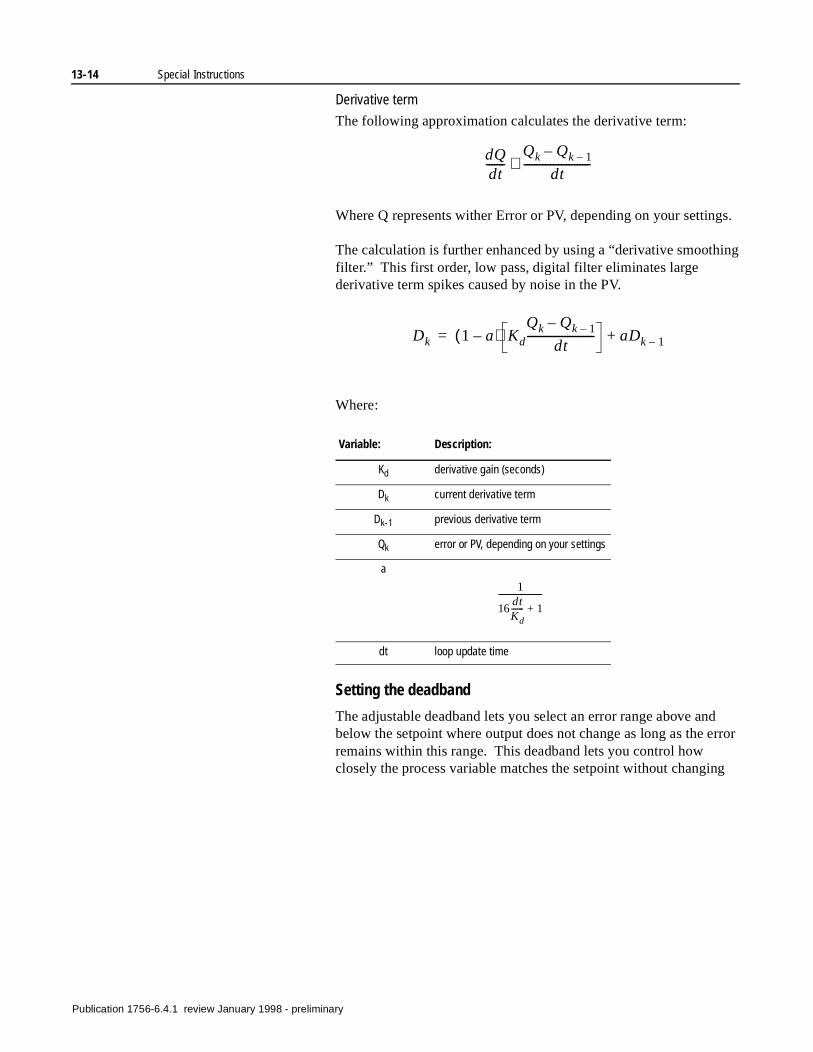
13-14 Special Instructions
ing
d rror
g
Derivative term
The following approximation calculates the derivative term:
Where Q represents wither Error or PV, depending on your settings.
The calculation is further enhanced by using a “derivative smoothfilter.” This first order, low pass, digital filter eliminates large derivative term spikes caused by noise in the PV.
Where:
Setting the deadband
The adjustable deadband lets you select an error range above anbelow the setpoint where output does not change as long as the eremains within this range. This deadband lets you control how closely the process variable matches the setpoint without changin
Variable: Description:
Kd derivative gain (seconds)
Dk current derivative term
Dk-1 previous derivative term
Qk error or PV, depending on your settings
a
dt loop update time
dQdt-------
Qk Qk 1––
dt-------------------------≅
Dk 1 a–( ) Kd
Qk Qk 1––
dt------------------------- aDk 1–+=
1
16dtKd------ 1+
----------------------
Publication 1756-6.4.1 review January 1998 - preliminary
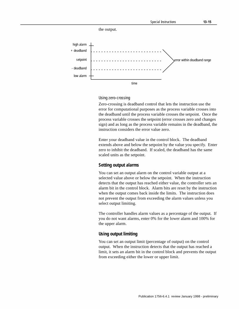
Special Instructions 13-15
the output.
Using zero-crossing
Zero-crossing is deadband control that lets the instruction use the error for computational purposes as the process variable crosses into the deadband until the process variable crosses the setpoint. Once the process variable crosses the setpoint (error crosses zero and changes sign) and as long as the process variable remains in the deadband, the instruction considers the error value zero.
Enter your deadband value in the control block. The deadband extends above and below the setpoint by the value you specify. Enter zero to inhibit the deadband. If scaled, the deadband has the same scaled units as the setpoint.
Setting output alarms
You can set an output alarm on the control variable output at a selected value above or below the setpoint. When the instruction detects that the output has reached either value, the controller sets an alarm bit in the control block. Alarm bits are reset by the instruction when the output comes back inside the limits. The instruction does not prevent the output from exceeding the alarm values unless you select output limiting.
The controller handles alarm values as a percentage of the output. If you do not want alarms, enter 0% for the lower alarm and 100% for the upper alarm.
Using output limiting
You can set an output limit (percentage of output) on the control output. When the instruction detects that the output has reached a limit, it sets an alarm bit in the control block and prevents the output from exceeding either the lower or upper limit.
error within deadband range
high alarm
+ deadband
setpoint
- deadband
low alarm
time
Publication 1756-6.4.1 review January 1998 - preliminary
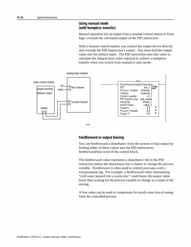
13-16 Special Instructions
ut
t by
cess
f the
ergy
Using manual mode(with bumpless transfer)
Manual operation lets an output from a manual control station or from logic override the calculated output of the PID instruction.
With a manual control station, you control the output device directly and override the PID instruction’s output. You must feed the outpvalue into the tieback input. The PID instruction uses this value tocalculate the integral term value required to achieve a bumpless transfer when you switch from manual to auto mode.
Feedforward or output biasing
You can feedforward a disturbance from the system or bias outpufeeding either of these values into the PID instructions feedforward/bias word of the control block.
The feedforward value represents a disturbance fed in the PID instruction before the disturbance has a chance to change the provariable. Feedforward is often used to control processes with a transportation lag. For example, a feedforward value representing “cold water poured into a warm mix” could boost the output value faster than waiting for the process variable to change as a result omixing.
A bias value can be used to compensate for steady-state loss of enfrom the controlled process.
15297
PVinput
analog input module
main control station
first channel
second channel
output tracking
(tieback input)
output
Publication 1756-6.4.1 review January 1998 - preliminary
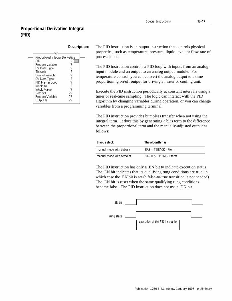
Special Instructions 13-17
Proportional Derivative Integral (PID)
Description: The PID instruction is an output instruction that controls physical properties, such as temperature, pressure, liquid level, or flow rate of process loops.
The PID instruction controls a PID loop with inputs from an analog input module and an output to an analog output module. For temperature control, you can convert the analog output to a time proportioning on/off output for driving a heater or cooling unit.
Execute the PID instruction periodically at constant intervals using a timer or real-time sampling. The logic can interact with the PID algorithm by changing variables during operation, or you can change variables from a programming terminal.
The PID instruction provides bumpless transfer when not using the integral term. It does this by generating a bias term to the difference between the proportional term and the manually-adjusted output as follows:
The PID instruction has only a .EN bit to indicate execution status. The .EN bit indicates that its qualifying rung conditions are true, in which case the .EN bit is set (a false-to-true transition is not needed). The .EN bit is reset when the same qualifying rung conditions become false. The PID instruction does not use a .DN bit.
If you select: The algorithm is:
manual mode with tieback BIAS = TIEBACK - Pterm
manual mode with setpoint BIAS = SETPOINT - Pterm
rung state
execution of the PID instruction
.EN bit
Publication 1756-6.4.1 review January 1998 - preliminary
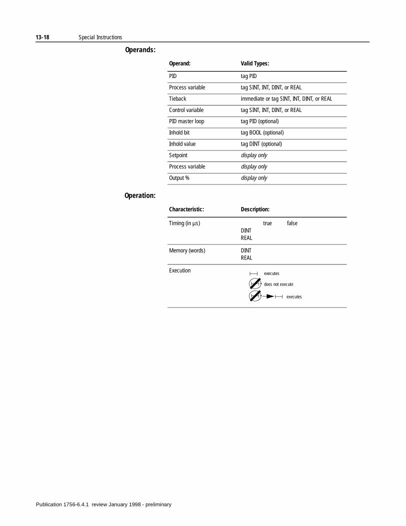
13-18 Special Instructions
Operands:
Operation:
Operand: Valid Types:
PID tag PID
Process variable tag SINT, INT, DINT, or REAL
Tieback immediate or tag SINT, INT, DINT, or REAL
Control variable tag SINT, INT, DINT, or REAL
PID master loop tag PID (optional)
Inhold bit tag BOOL (optional)
Inhold value tag DINT (optional)
Setpoint display only
Process variable display only
Output % display only
Characteristic: Description:
Timing (in µs) true falseDINTREAL
Memory (words) DINTREAL
Execution executes
does not execute
executes
Publication 1756-6.4.1 review January 1998 - preliminary
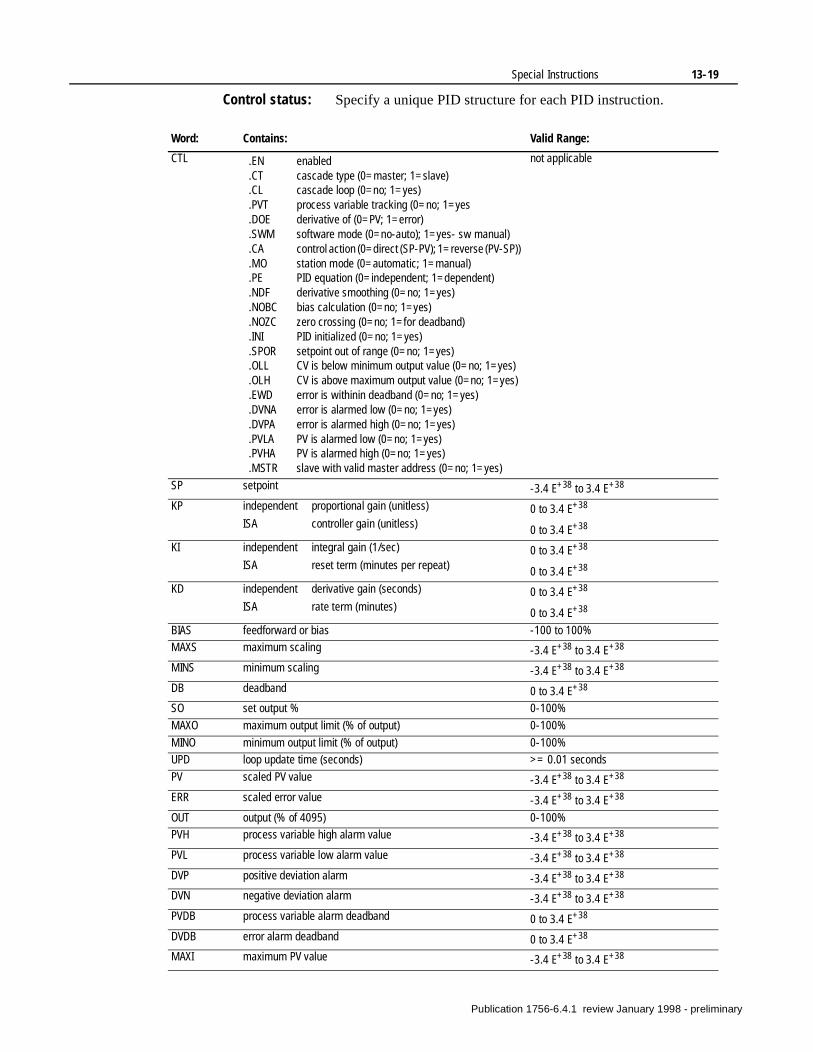
Special Instructions 13-19
Control status: Specify a unique PID structure for each PID instruction.
Word: Contains: Valid Range:
CTL .EN enabled.CT cascade type (0=master; 1=slave).CL cascade loop (0=no; 1=yes).PVT process variable tracking (0=no; 1=yes.DOE derivative of (0=PV; 1=error).SWM software mode (0=no-auto); 1=yes- sw manual).CA control action (0=direct (SP-PV); 1=reverse (PV-SP)).MO station mode (0=automatic; 1=manual).PE PID equation (0=independent; 1=dependent).NDF derivative smoothing (0=no; 1=yes).NOBC bias calculation (0=no; 1=yes).NOZC zero crossing (0=no; 1=for deadband).INI PID initialized (0=no; 1=yes).SPOR setpoint out of range (0=no; 1=yes).OLL CV is below minimum output value (0=no; 1=yes) .OLH CV is above maximum output value (0=no; 1=yes).EWD error is withinin deadband (0=no; 1=yes).DVNA error is alarmed low (0=no; 1=yes).DVPA error is alarmed high (0=no; 1=yes).PVLA PV is alarmed low (0=no; 1=yes).PVHA PV is alarmed high (0=no; 1=yes).MSTR slave with valid master address (0=no; 1=yes)
not applicable
SP setpoint -3.4 E+38 to 3.4 E+38
KP independent proportional gain (unitless)
ISA controller gain (unitless)0 to 3.4 E+38
0 to 3.4 E+38
KI independent integral gain (1/sec)
ISA reset term (minutes per repeat)0 to 3.4 E+38
0 to 3.4 E+38
KD independent derivative gain (seconds)
ISA rate term (minutes)0 to 3.4 E+38
0 to 3.4 E+38
BIAS feedforward or bias -100 to 100%
MAXS maximum scaling -3.4 E+38 to 3.4 E+38
MINS minimum scaling -3.4 E+38 to 3.4 E+38
DB deadband 0 to 3.4 E+38
SO set output % 0-100%
MAXO maximum output limit (% of output) 0-100%
MINO minimum output limit (% of output) 0-100%
UPD loop update time (seconds) >= 0.01 seconds
PV scaled PV value -3.4 E+38 to 3.4 E+38
ERR scaled error value -3.4 E+38 to 3.4 E+38
OUT output (% of 4095) 0-100%
PVH process variable high alarm value -3.4 E+38 to 3.4 E+38
PVL process variable low alarm value -3.4 E+38 to 3.4 E+38
DVP positive deviation alarm -3.4 E+38 to 3.4 E+38
DVN negative deviation alarm -3.4 E+38 to 3.4 E+38
PVDB process variable alarm deadband 0 to 3.4 E+38
DVDB error alarm deadband 0 to 3.4 E+38
MAXI maximum PV value -3.4 E+38 to 3.4 E+38
Publication 1756-6.4.1 review January 1998 - preliminary
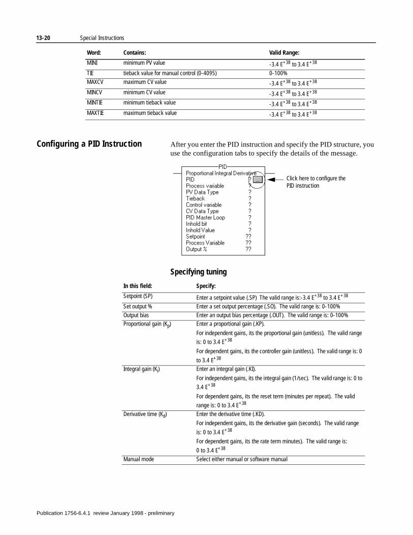
13-20 Special Instructions
Configuring a PID Instruction After you enter the PID instruction and specify the PID structure, you use the configuration tabs to specify the details of the message.
Specifying tuning
MINI minimum PV value -3.4 E+38 to 3.4 E+38
TIE tieback value for manual control (0-4095) 0-100%
MAXCV maximum CV value -3.4 E+38 to 3.4 E+38
MINCV minimum CV value -3.4 E+38 to 3.4 E+38
MINTIE minimum tieback value -3.4 E+38 to 3.4 E+38
MAXTIE maximum tieback value -3.4 E+38 to 3.4 E+38
Word: Contains: Valid Range:
In this field: Specify:
Setpoint (SP) Enter a setpoint value (.SP) The valid range is:-3.4 E+38 to 3.4 E+38
Set output % Enter a set output percentage (.SO). The valid range is: 0-100%
Output bias Enter an output bias percentage (.OUT). The valid range is: 0-100%
Proportional gain (Kp) Enter a proportional gain (.KP).
For independent gains, its the proportional gain (unitless). The valid range
is: 0 to 3.4 E+38
For dependent gains, its the controller gain (unitless). The valid range is: 0
to 3.4 E+38
Integral gain (Ki) Enter an integral gain (.KI).
For independent gains, its the integral gain (1/sec). The valid range is: 0 to
3.4 E+38
For dependent gains, its the reset term (minutes per repeat). The valid
range is: 0 to 3.4 E+38
Derivative time (Kd) Enter the derivative time (.KD).
For independent gains, its the derivative gain (seconds). The valid range
is: 0 to 3.4 E+38
For dependent gains, its the rate term minutes). The valid range is:
0 to 3.4 E+38
Manual mode Select either manual or software manual
Click here to configure the PID instruction
Publication 1756-6.4.1 review January 1998 - preliminary
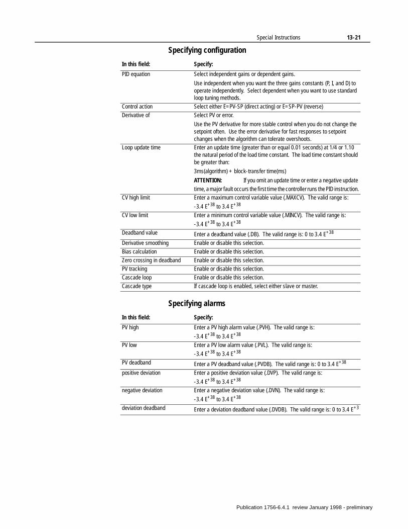
Special Instructions 13-21
Specifying configuration
Specifying alarms
In this field: Specify:
PID equation Select independent gains or dependent gains.
Use independent when you want the three gains constants (P, I, and D) to operate independently. Select dependent when you want to use standard loop tuning methods.
Control action Select either E=PV-SP (direct acting) or E=SP-PV (reverse)
Derivative of Select PV or error.
Use the PV derivative for more stable control when you do not change the setpoint often. Use the error derivative for fast responses to setpoint changes when the algorithm can tolerate overshoots.
Loop update time Enter an update time (greater than or equal 0.01 seconds) at 1/4 or 1.10 the natural period of the load time constant. The load time constant should be greater than:
3ms(algorithm) + block-transfer time(ms)
ATTENTION: If you omit an update time or enter a negative update
time, a major fault occurs the first time the controller runs the PID instruction.
CV high limit Enter a maximum control variable value (.MAXCV). The valid range is:
-3.4 E+38 to 3.4 E+38
CV low limit Enter a minimum control variable value (.MINCV). The valid range is:
-3.4 E+38 to 3.4 E+38
Deadband value Enter a deadband value (.DB). The valid range is: 0 to 3.4 E+38
Derivative smoothing Enable or disable this selection.
Bias calculation Enable or disable this selection.
Zero crossing in deadband Enable or disable this selection.
PV tracking Enable or disable this selection.
Cascade loop Enable or disable this selection.
Cascade type If cascade loop is enabled, select either slave or master.
In this field: Specify:
PV high Enter a PV high alarm value (.PVH). The valid range is:
-3.4 E+38 to 3.4 E+38
PV low Enter a PV low alarm value (.PVL). The valid range is:
-3.4 E+38 to 3.4 E+38
PV deadband Enter a PV deadband value (.PVDB). The valid range is: 0 to 3.4 E+38
positive deviation Enter a positive deviation value (.DVP). The valid range is:
-3.4 E+38 to 3.4 E+38
negative deviation Enter a negative deviation value (.DVN). The valid range is:
-3.4 E+38 to 3.4 E+38
deviation deadband Enter a deviation deadband value (.DVDB). The valid range is: 0 to 3.4 E+3
Publication 1756-6.4.1 review January 1998 - preliminary
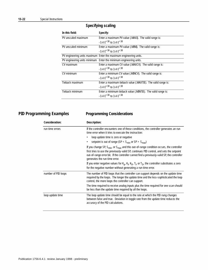
13-22 Special Instructions
Specifying scaling
PID Programming Examples Programming Considerations
In this field: Specify:
PV unscaled maximum Enter a maximum PV value (.MAXI). The valid range is:
-3.4 E+38 to 3.4 E+38
PV unscaled minimum Enter a maximum PV value (.MINI). The valid range is:
-3.4 E+38 to 3.4 E+38
PV engineering units maximum Enter the maximum engineering units.
PV engineering units minimum Enter the minimum engineering units.
CV maximum Enter a maximum CV value (.MAXCV). The valid range is:
-3.4 E+38 to 3.4 E+38
CV minimum Enter a minimum CV value (.MINCV). The valid range is:
-3.4 E+38 to 3.4 E+38
Tieback maximum Enter a maximum tieback value (.MAXTIE). The valid range is:
-3.4 E+38 to 3.4 E+38
Tieback minimum Enter a minimum tieback value (.MINTIE). The valid range is:
-3.4 E+38 to 3.4 E+38
Consideration: Description:
run time errors If the controller encounters one of these conditions, the controller generates an run time error when it tries to execute the instruction:
• loop update time is zero or negative
• setpoint is out of range (SP < Smin or SP > Smax)
If you change SP, Smin, or Smax and this out-of-range condition occurs, the controller first tries to use the previously-valid SP, continues PID control, and sets the setpoint out-of-range error bit. If the controller cannot find a previously-valid SP, the controller generates the run time error.
If you enter negative values for Kp, KI, KD, TI, or TD, the controller substitutes a zero
for the negative number without generating a run time error.
number of PID loops The number of PID loops that the controller can support depends on the update time required by the loops. The longer the update time and the less-sophisticated the loop control, the more loops the controller can support.
The time required to receive analog inputs plus the time required for one scan should be less than the update time required by all the loops.
loop update time The loop update time should be equal to the rate at which the PID rung changes between false and true. Deviation in toggle rate from the update time reduces the accuracy of the PID calculations.
Publication 1756-6.4.1 review January 1998 - preliminary
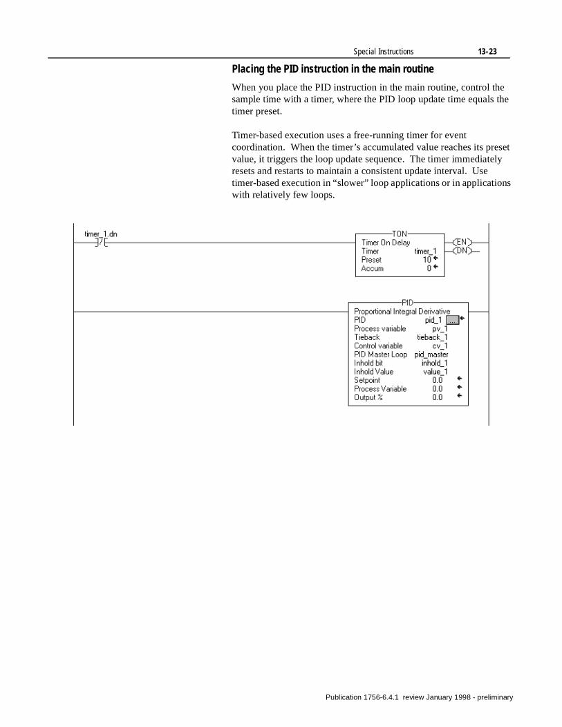
Special Instructions 13-23
set ly
Placing the PID instruction in the main routine
When you place the PID instruction in the main routine, control the sample time with a timer, where the PID loop update time equals the timer preset.
Timer-based execution uses a free-running timer for event coordination. When the timer’s accumulated value reaches its prevalue, it triggers the loop update sequence. The timer immediateresets and restarts to maintain a consistent update interval. Use timer-based execution in “slower” loop applications or in applicationswith relatively few loops.
Publication 1756-6.4.1 review January 1998 - preliminary
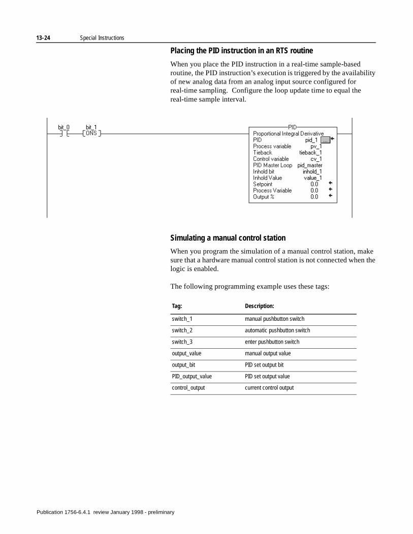
13-24 Special Instructions
ity
ke the
Placing the PID instruction in an RTS routine
When you place the PID instruction in a real-time sample-based routine, the PID instruction’s execution is triggered by the availabilof new analog data from an analog input source configured for real-time sampling. Configure the loop update time to equal the real-time sample interval.
Simulating a manual control station
When you program the simulation of a manual control station, masure that a hardware manual control station is not connected whenlogic is enabled.
The following programming example uses these tags:
Tag: Description:
switch_1 manual pushbutton switch
switch_2 automatic pushbutton switch
switch_3 enter pushbutton switch
output_value manual output value
output_bit PID set output bit
PID_output_value PID set output value
control_output current control output
Publication 1756-6.4.1 review January 1998 - preliminary
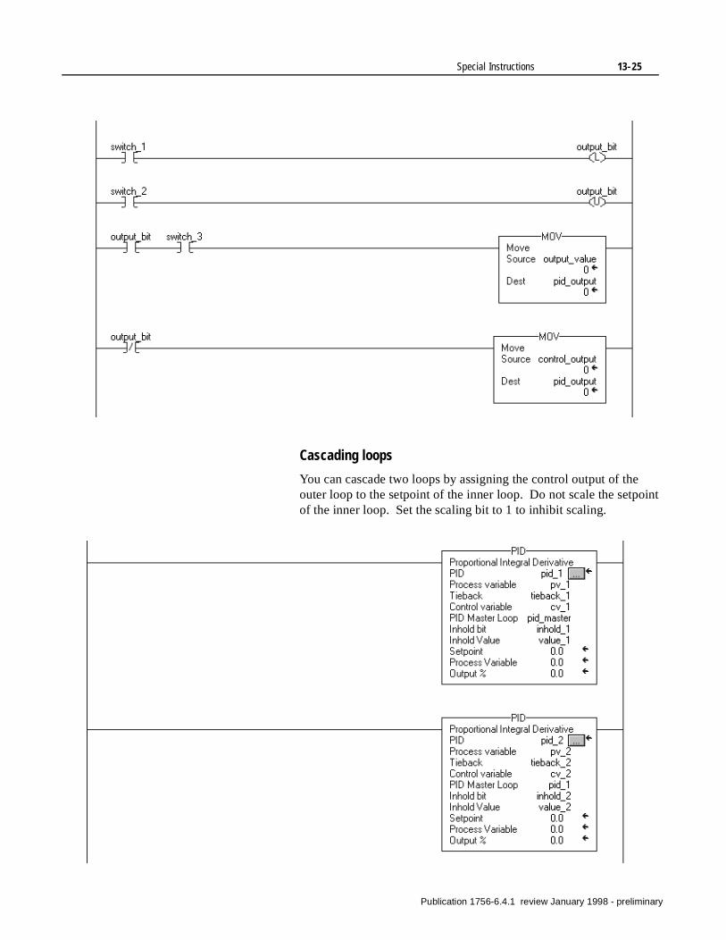
Special Instructions 13-25
Cascading loops
You can cascade two loops by assigning the control output of the outer loop to the setpoint of the inner loop. Do not scale the setpoint of the inner loop. Set the scaling bit to 1 to inhibit scaling.
Publication 1756-6.4.1 review January 1998 - preliminary
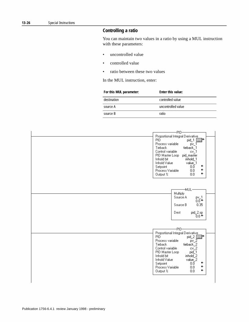
13-26 Special Instructions
Controlling a ratio
You can maintain two values in a ratio by using a MUL instruction with these parameters:
• uncontrolled value
• controlled value
• ratio between these two values
In the MUL instruction, enter:
For this MUL parameter: Enter this value:
destination controlled value
source A uncontrolled value
source B ratio
Publication 1756-6.4.1 review January 1998 - preliminary
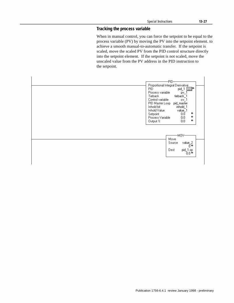
Special Instructions 13-27
Tracking the process variable
When in manual control, you can force the setpoint to be equal to the process variable (PV) by moving the PV into the setpoint element. to achieve a smooth manual-to-automatic transfer. If the setpoint is scaled, move the scaled PV from the PID control structure directly into the setpoint element. If the setpoint is not scaled, move the unscaled value from the PV address in the PID instruction to the setpoint.
Publication 1756-6.4.1 review January 1998 - preliminary

13-28 Special Instructions
Publication 1756-6.4.1 review January 1998 - preliminary
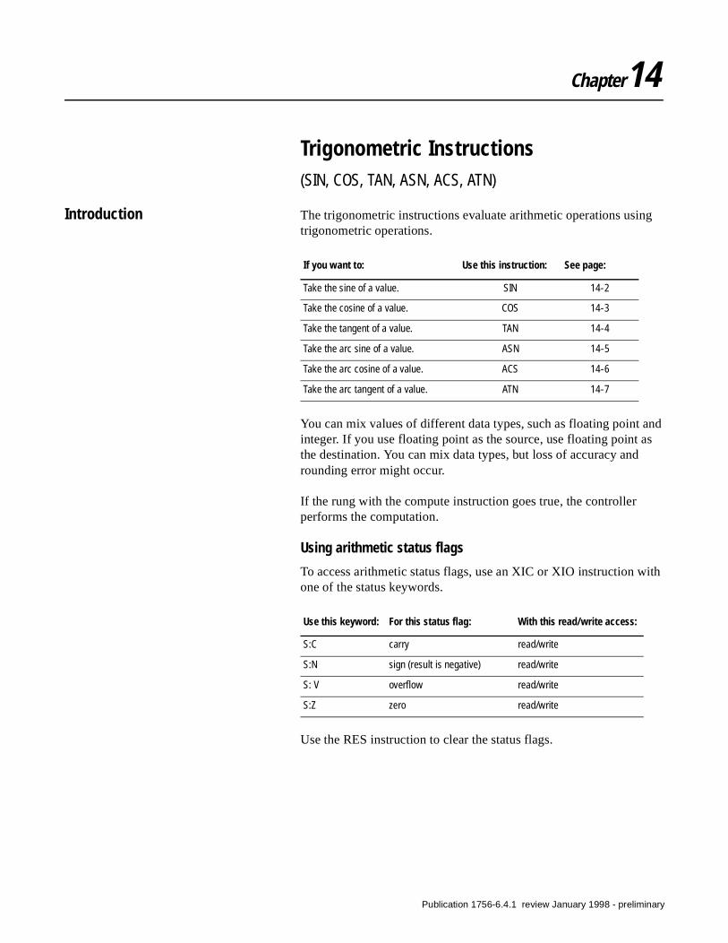
Chapter14
Trigonometric Instructions(SIN, COS, TAN, ASN, ACS, ATN)
Introduction The trigonometric instructions evaluate arithmetic operations using trigonometric operations.
You can mix values of different data types, such as floating point and integer. If you use floating point as the source, use floating point as the destination. You can mix data types, but loss of accuracy and rounding error might occur.
If the rung with the compute instruction goes true, the controller performs the computation.
Using arithmetic status flags
To access arithmetic status flags, use an XIC or XIO instruction with one of the status keywords.
Use the RES instruction to clear the status flags.
If you want to: Use this instruction: See page:
Take the sine of a value. SIN 14-2
Take the cosine of a value. COS 14-3
Take the tangent of a value. TAN 14-4
Take the arc sine of a value. ASN 14-5
Take the arc cosine of a value. ACS 14-6
Take the arc tangent of a value. ATN 14-7
Use this keyword: For this status flag: With this read/write access:
S:C carry read/write
S:N sign (result is negative) read/write
S: V overflow read/write
S:Z zero read/write
Publication 1756-6.4.1 review January 1998 - preliminary
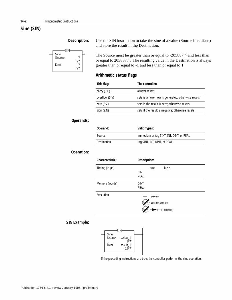
14-2 Trigonometric Instructions
Sine (SIN)
Description: Use the SIN instruction to take the sine of a value (Source in radians) and store the result in the Destination.
The Source must be greater than or equal to -205887.4 and less than or equal to 205887.4. The resulting value in the Destination is always greater than or equal to -1 and less than or equal to 1.
Arithmetic status flags
Operands:
Operation:
SIN Example:
This flag: The controller:
carry (S:C) always resets
overflow (S:V) sets is an overflow is generated; otherwise resets
zero (S:Z) sets is the result is zero; otherwise resets
sign (S:N) sets if the result is negative; otherwise resets
Operand: Valid Types:
Source immediate or tag SINT, INT, DINT, or REAL
Destination tag SINT, INT, DINT, or REAL
Characteristic: Description:
Timing (in µs) true falseDINTREAL
Memory (words) DINTREAL
Execution executes
does not execute
executes
If the preceding instructions are true, the controller performs the sine operation.
Publication 1756-6.4.1 review January 1998 - preliminary

Trigonometric Instructions 14-3
Cosine (COS)
Description: Use the COS instruction to take the cosine of a value (Source in radians) and store the result in the Destination.
The Source must be greater than or equal to -205887.4 and less than or equal to 205887.4. The resulting value in the Destination is always greater than or equal to -1 and less than or equal to 1.
Arithmetic status flags
Operands:
Operation:
COS Example:
This flag: The controller:
carry (S:C) always resets
overflow (S:V) sets is an overflow is generated; otherwise resets
zero (S:Z) sets is the result is zero; otherwise resets
sign (S:N) sets if the result is negative; otherwise resets
Operand: Valid Types:
Source immediate or tag SINT, INT, DINT, or REAL
Destination tag SINT, INT, DINT, or REAL
Characteristic: Description:
Timing (in µs) true falseDINTREAL
Memory (words) DINTREAL
Execution executes
does not execute
executes
If the preceding instructions are true, the controller performs the cosine operation.
Publication 1756-6.4.1 review January 1998 - preliminary
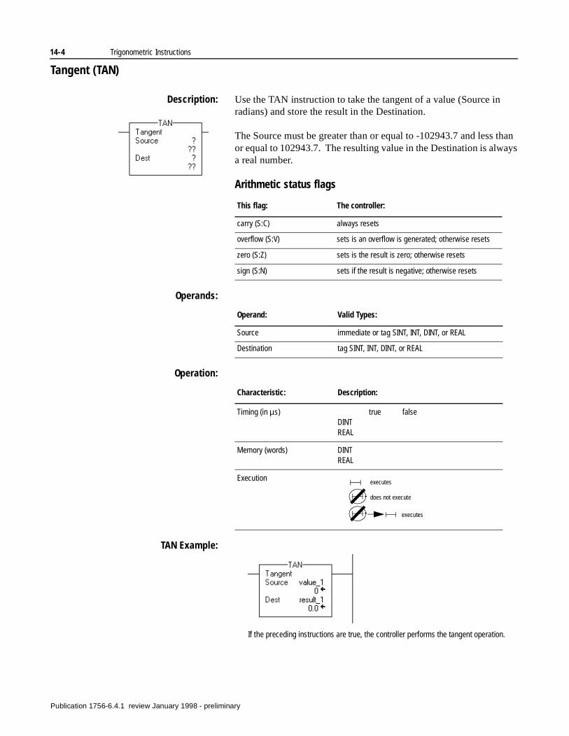
14-4 Trigonometric Instructions
Tangent (TAN)
Description: Use the TAN instruction to take the tangent of a value (Source in radians) and store the result in the Destination.
The Source must be greater than or equal to -102943.7 and less than or equal to 102943.7. The resulting value in the Destination is always a real number.
Arithmetic status flags
Operands:
Operation:
TAN Example:
This flag: The controller:
carry (S:C) always resets
overflow (S:V) sets is an overflow is generated; otherwise resets
zero (S:Z) sets is the result is zero; otherwise resets
sign (S:N) sets if the result is negative; otherwise resets
Operand: Valid Types:
Source immediate or tag SINT, INT, DINT, or REAL
Destination tag SINT, INT, DINT, or REAL
Characteristic: Description:
Timing (in µs) true falseDINTREAL
Memory (words) DINTREAL
Execution executes
does not execute
executes
If the preceding instructions are true, the controller performs the tangent operation.
Publication 1756-6.4.1 review January 1998 - preliminary
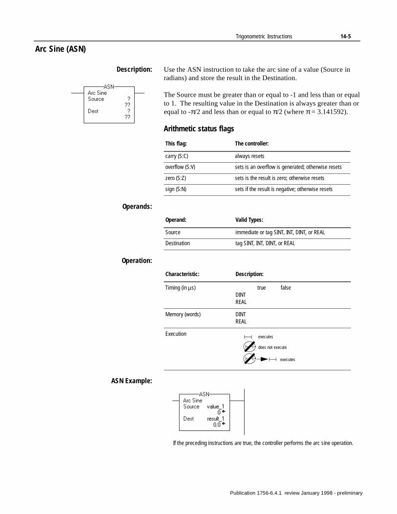
Trigonometric Instructions 14-5
Arc Sine (ASN)
Description: Use the ASN instruction to take the arc sine of a value (Source in radians) and store the result in the Destination.
The Source must be greater than or equal to -1 and less than or equal to 1. The resulting value in the Destination is always greater than or equal to -π/2 and less than or equal to π/2 (where π = 3.141592).
Arithmetic status flags
Operands:
Operation:
ASN Example:
This flag: The controller:
carry (S:C) always resets
overflow (S:V) sets is an overflow is generated; otherwise resets
zero (S:Z) sets is the result is zero; otherwise resets
sign (S:N) sets if the result is negative; otherwise resets
Operand: Valid Types:
Source immediate or tag SINT, INT, DINT, or REAL
Destination tag SINT, INT, DINT, or REAL
Characteristic: Description:
Timing (in µs) true falseDINTREAL
Memory (words) DINTREAL
Execution executes
does not execute
executes
If the preceding instructions are true, the controller performs the arc sine operation.
Publication 1756-6.4.1 review January 1998 - preliminary
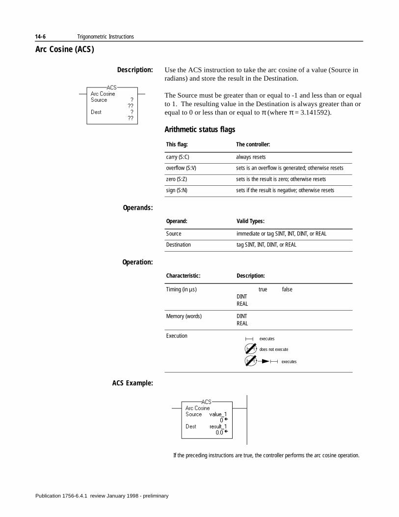
14-6 Trigonometric Instructions
Arc Cosine (ACS)
Description: Use the ACS instruction to take the arc cosine of a value (Source in radians) and store the result in the Destination.
The Source must be greater than or equal to -1 and less than or equal to 1. The resulting value in the Destination is always greater than or equal to 0 or less than or equal to π (where π = 3.141592).
Arithmetic status flags
Operands:
Operation:
ACS Example:
This flag: The controller:
carry (S:C) always resets
overflow (S:V) sets is an overflow is generated; otherwise resets
zero (S:Z) sets is the result is zero; otherwise resets
sign (S:N) sets if the result is negative; otherwise resets
Operand: Valid Types:
Source immediate or tag SINT, INT, DINT, or REAL
Destination tag SINT, INT, DINT, or REAL
Characteristic: Description:
Timing (in µs) true falseDINTREAL
Memory (words) DINTREAL
Execution executes
does not execute
executes
If the preceding instructions are true, the controller performs the arc cosine operation.
Publication 1756-6.4.1 review January 1998 - preliminary
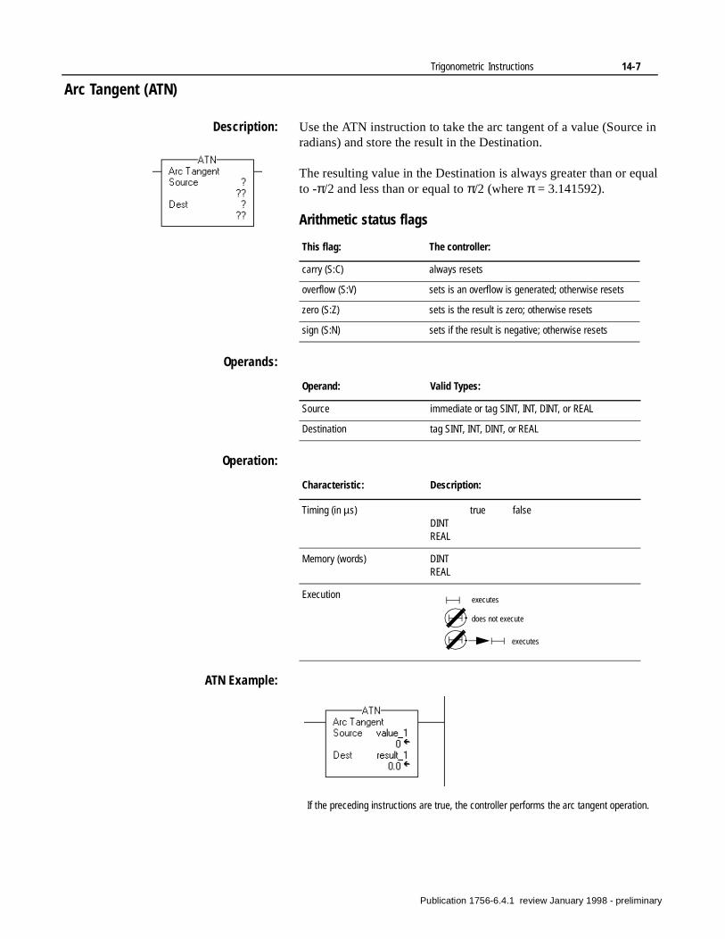
Trigonometric Instructions 14-7
Arc Tangent (ATN)
Description: Use the ATN instruction to take the arc tangent of a value (Source in radians) and store the result in the Destination.
The resulting value in the Destination is always greater than or equal to -π/2 and less than or equal to π/2 (where π = 3.141592).
Arithmetic status flags
Operands:
Operation:
ATN Example:
This flag: The controller:
carry (S:C) always resets
overflow (S:V) sets is an overflow is generated; otherwise resets
zero (S:Z) sets is the result is zero; otherwise resets
sign (S:N) sets if the result is negative; otherwise resets
Operand: Valid Types:
Source immediate or tag SINT, INT, DINT, or REAL
Destination tag SINT, INT, DINT, or REAL
Characteristic: Description:
Timing (in µs) true falseDINTREAL
Memory (words) DINTREAL
Execution executes
does not execute
executes
If the preceding instructions are true, the controller performs the arc tangent operation.
Publication 1756-6.4.1 review January 1998 - preliminary

14-8 Trigonometric Instructions
Notes:
Publication 1756-6.4.1 review January 1998 - preliminary
Chapter15
Advanced Math Instructions(LN, LOG, XPY)
Introduction The advanced math instructions evaluate operations using an expression or a specific arithmetic instruction.
You can mix values of different data types, such as floating point and integer. If you use floating point as the source, use floating point as the destination. You can mix data types, but loss of accuracy and rounding error might occur.
If the rung with the compute instruction goes true, the controller performs the computation.
Using arithmetic status flags
To access arithmetic status flags, use an XIC or XIO instruction with one of the status keywords.
Use the RES instruction to clear the status flags.
If you want to: Use this instruction: See page:
Take the natural log of a value. LN 15-2
Take the log base 10 of a value. LOG 15-3
Raise a value to the power of another value.
XPY 15-4
Use this keyword: For this status flag: With this read/write access:
S:C carry read/write
S:N sign (result is negative) read/write
S: V overflow read/write
S:Z zero read/write
Publication 1756-6.4.1 review January 1998 - preliminary
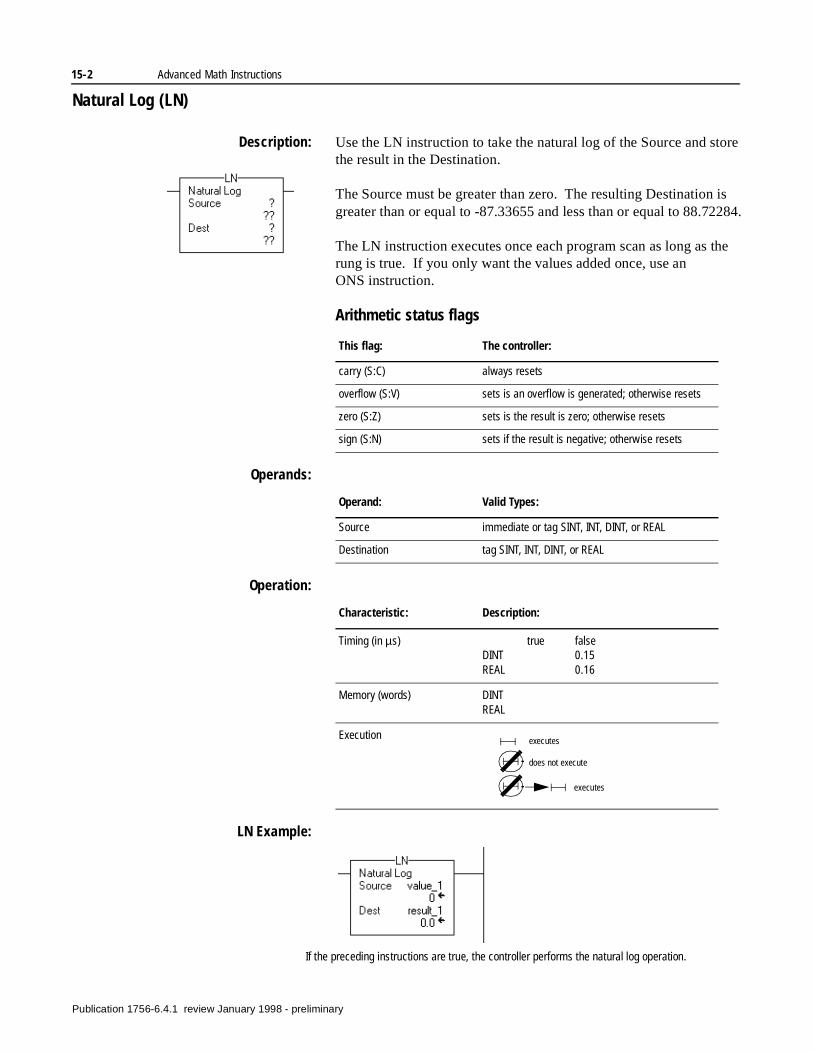
15-2 Advanced Math Instructions
Natural Log (LN)
Description: Use the LN instruction to take the natural log of the Source and store the result in the Destination.
The Source must be greater than zero. The resulting Destination is greater than or equal to -87.33655 and less than or equal to 88.72284.
The LN instruction executes once each program scan as long as the rung is true. If you only want the values added once, use an ONS instruction.
Arithmetic status flags
Operands:
Operation:
LN Example:
This flag: The controller:
carry (S:C) always resets
overflow (S:V) sets is an overflow is generated; otherwise resets
zero (S:Z) sets is the result is zero; otherwise resets
sign (S:N) sets if the result is negative; otherwise resets
Operand: Valid Types:
Source immediate or tag SINT, INT, DINT, or REAL
Destination tag SINT, INT, DINT, or REAL
Characteristic: Description:
Timing (in µs) true falseDINT 0.15REAL 0.16
Memory (words) DINTREAL
Execution executes
does not execute
executes
If the preceding instructions are true, the controller performs the natural log operation.
Publication 1756-6.4.1 review January 1998 - preliminary
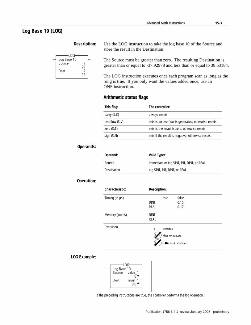
Advanced Math Instructions 15-3
Log Base 10 (LOG)
Description: Use the LOG instruction to take the log base 10 of the Source and store the result in the Destination.
The Source must be greater than zero. The resulting Destination is greater than or equal to -37.92978 and less than or equal to 38.53184.
The LOG instruction executes once each program scan as long as the rung is true. If you only want the values added once, use an ONS instruction.
Arithmetic status flags
Operands:
Operation:
LOG Example:
This flag: The controller:
carry (S:C) always resets
overflow (S:V) sets is an overflow is generated; otherwise resets
zero (S:Z) sets is the result is zero; otherwise resets
sign (S:N) sets if the result is negative; otherwise resets
Operand: Valid Types:
Source immediate or tag SINT, INT, DINT, or REAL
Destination tag SINT, INT, DINT, or REAL
Characteristic: Description:
Timing (in µs) true falseDINT 0.15REAL 0.17
Memory (words) DINTREAL
Execution executes
does not execute
executes
If the preceding instructions are true, the controller performs the log operation.
Publication 1756-6.4.1 review January 1998 - preliminary
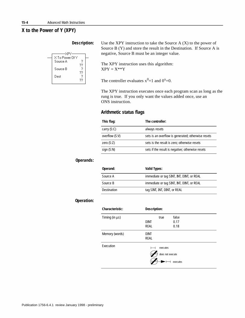
15-4 Advanced Math Instructions
X to the Power of Y (XPY)
Description: Use the XPY instruction to take the Source A (X) to the power of Source B (Y) and store the result in the Destination. If Source A is negative, Source B must be an integer value.
The XPY instruction uses this algorithm:XPY = X**Y
The controller evaluates x0=1 and 0x=0.
The XPY instruction executes once each program scan as long as the rung is true. If you only want the values added once, use an ONS instruction.
Arithmetic status flags
Operands:
Operation:
This flag: The controller:
carry (S:C) always resets
overflow (S:V) sets is an overflow is generated; otherwise resets
zero (S:Z) sets is the result is zero; otherwise resets
sign (S:N) sets if the result is negative; otherwise resets
Operand: Valid Types:
Source A immediate or tag SINT, INT, DINT, or REAL
Source B immediate or tag SINT, INT, DINT, or REAL
Destination tag SINT, INT, DINT, or REAL
Characteristic: Description:
Timing (in µs) true falseDINT 0.17REAL 0.18
Memory (words) DINTREAL
Execution executes
does not execute
executes
Publication 1756-6.4.1 review January 1998 - preliminary
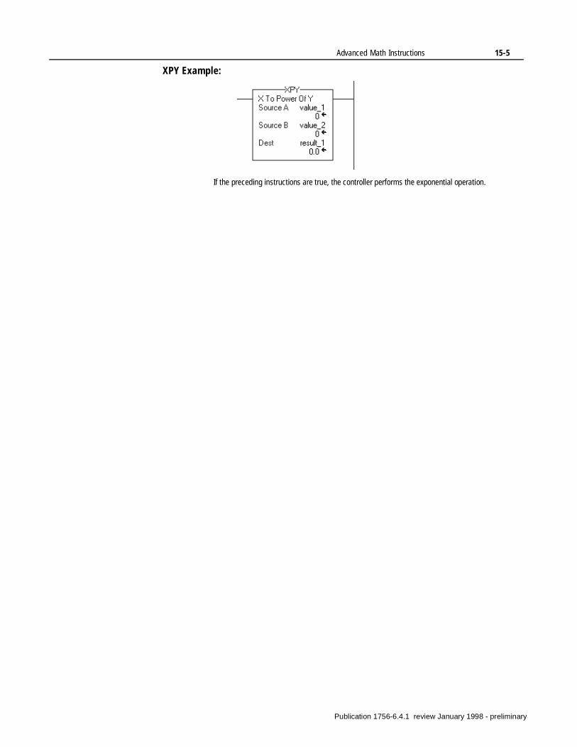
Advanced Math Instructions 15-5
XPY Example:
If the preceding instructions are true, the controller performs the exponential operation.
Publication 1756-6.4.1 review January 1998 - preliminary

15-6 Advanced Math Instructions
Notes:
Publication 1756-6.4.1 review January 1998 - preliminary

Chapter16
Math Conversion Instructions(DEG, RAD, TOD, FRD)
Introduction The math conversion instructions convert values.
If the rung with the compute instruction goes true, the controller performs the computation.
Using arithmetic status flags
To access arithmetic status flags, use an XIC or XIO instruction with one of the status keywords.
Use the RES instruction to clear the status flags.
If you want to: Use this instruction: See page:
Convert radians into degrees. DEG 16-2
Convert degrees into radians. RAD 16-3
Convert an integer value to a BCD value.
TOD 16-4
Convert a BCD value to an integer value.
FRD 16-5
Use this keyword: For this status flag: With this read/write access:
S:C carry read/write
S:N sign (result is negative) read/write
S: V overflow read/write
S:Z zero read/write
Publication 1756-6.4.1 review January 1998 - preliminary
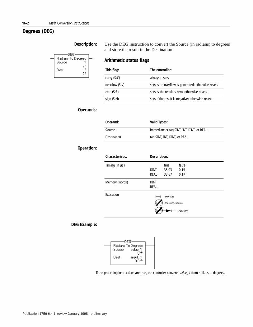
16-2 Math Conversion Instructions
Degrees (DEG)
Description: Use the DEG instruction to convert the Source (in radians) to degrees and store the result in the Destination.
Arithmetic status flags
Operands:
Operation:
DEG Example:
This flag: The controller:
carry (S:C) always resets
overflow (S:V) sets is an overflow is generated; otherwise resets
zero (S:Z) sets is the result is zero; otherwise resets
sign (S:N) sets if the result is negative; otherwise resets
Operand: Valid Types:
Source immediate or tag SINT, INT, DINT, or REAL
Destination tag SINT, INT, DINT, or REAL
Characteristic: Description:
Timing (in µs) true falseDINT 35.03 0.15REAL 33.67 0.17
Memory (words) DINTREAL
Execution executes
does not execute
executes
If the preceding instructions are true, the controller converts value_1 from radians to degrees.
Publication 1756-6.4.1 review January 1998 - preliminary
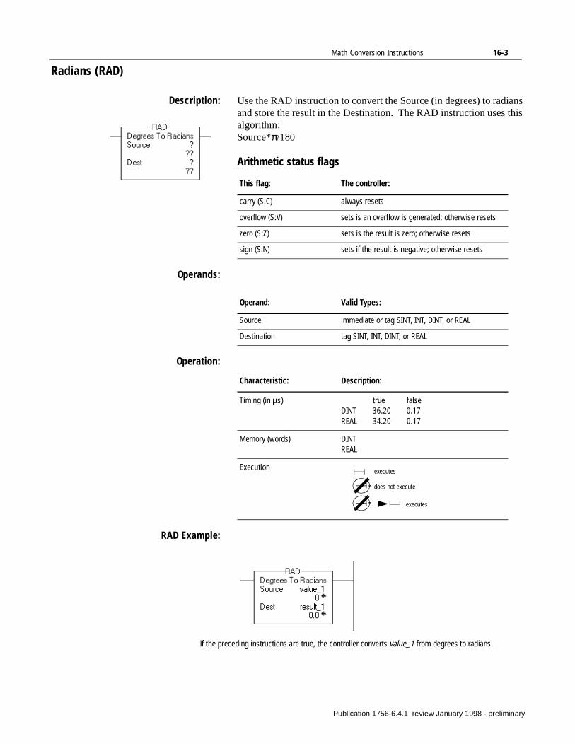
Math Conversion Instructions 16-3
Radians (RAD)
Description: Use the RAD instruction to convert the Source (in degrees) to radians and store the result in the Destination. The RAD instruction uses this algorithm:Source*π/180
Arithmetic status flags
Operands:
Operation:
RAD Example:
This flag: The controller:
carry (S:C) always resets
overflow (S:V) sets is an overflow is generated; otherwise resets
zero (S:Z) sets is the result is zero; otherwise resets
sign (S:N) sets if the result is negative; otherwise resets
Operand: Valid Types:
Source immediate or tag SINT, INT, DINT, or REAL
Destination tag SINT, INT, DINT, or REAL
Characteristic: Description:
Timing (in µs) true falseDINT 36.20 0.17REAL 34.20 0.17
Memory (words) DINTREAL
Execution executes
does not execute
executes
If the preceding instructions are true, the controller converts value_1 from degrees to radians.
Publication 1756-6.4.1 review January 1998 - preliminary
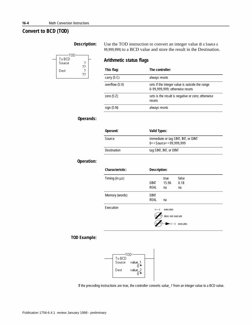
16-4 Math Conversion Instructions
Convert to BCD (TOD)
Description: Use the TOD instruction to convert an integer value (0 ≤ Source ≤
99,999,999) to a BCD value and store the result in the Destination.
Arithmetic status flags
Operands:
Operation:
TOD Example:
This flag: The controller:
carry (S:C) always resets
overflow (S:V) sets if the integer value is outside the range 0-99,999,999; otherwise resets
zero (S:Z) sets is the result is negative or zero; otherwise resets
sign (S:N) always resets
Operand: Valid Types:
Source immediate or tag SINT, INT, or DINT0<=Source<=99,999,999
Destination tag SINT, INT, or DINT
Characteristic: Description:
Timing (in µs) true falseDINT 15.96 0.18REAL na na
Memory (words) DINTREAL na
Execution executes
does not execute
executes
If the preceding instructions are true, the controller converts value_1 from an integer value to a BCD value.
Publication 1756-6.4.1 review January 1998 - preliminary
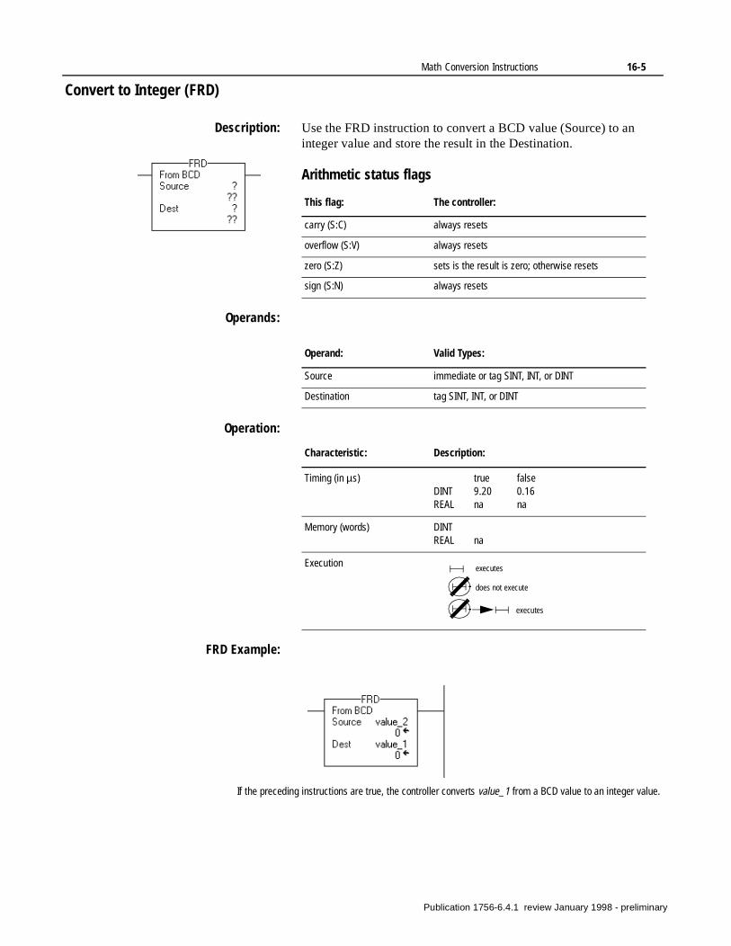
Math Conversion Instructions 16-5
Convert to Integer (FRD)
Description: Use the FRD instruction to convert a BCD value (Source) to an integer value and store the result in the Destination.
Arithmetic status flags
Operands:
Operation:
FRD Example:
This flag: The controller:
carry (S:C) always resets
overflow (S:V) always resets
zero (S:Z) sets is the result is zero; otherwise resets
sign (S:N) always resets
Operand: Valid Types:
Source immediate or tag SINT, INT, or DINT
Destination tag SINT, INT, or DINT
Characteristic: Description:
Timing (in µs) true falseDINT 9.20 0.16REAL na na
Memory (words) DINTREAL na
Execution executes
does not execute
executes
If the preceding instructions are true, the controller converts value_1 from a BCD value to an integer value.
Publication 1756-6.4.1 review January 1998 - preliminary

16-6 Math Conversion Instructions
Notes:
Publication 1756-6.4.1 review January 1998 - preliminary
Chapter17
Motion Concepts
Introduction The ControlLogix system takes a new approach to motion control. In the ControlLogix system, the motion application program execution and motion planner functions reside in the Logix5550 controller, creating highly-integrated motion and sequential control. A smart axis motion module receives coarse position commands from the ControlLogix controller and closes a high-speed (100µs) fine planner, position loop, and velocity loop. The ControlLogix chassis allows high-speed synchronization of one or more ControlLogix processors and up to 16 motion control modules, which means one chassis can support up to 32 axes.
RSLogix5000 programming software provides complete motion configuration and application programming, which eliminates the need to purchase and maintain multiple programming tools. An axis wizard guides you through assigning and configuring an axis. The axis wizard also initiates a powerful auto-tune utility which you can use to determine all axis gains and dynamics.
The Logix5550 controller uses 27 high-level motion instructions, including instructions for homing, jogging, point-to-point positioning, complex gearing, and high-speed registration. You can insert these instructions directly into the ladder diagram application program.
Publication 1756-6.4.1 review January 1998 - preliminary
17-2 Motion Concepts
nd
s
e
to
Identifying the Components of the ControlLogix Motion System
The Logix5550 Controller (1756-L1)
The Logix5550 controller is the main component in the ControlLogix system. It supports sequential and motion functions, and it performs all of the motion command execution and motion trajectory planner functions. You can use one or more Logix5550 controllers in each chassis, and each controller can control up to 16 motion modules.
The Logix5550 controller supports the following motion features:
• An extensive command set including 27 motion instructions
• A high-speed motion task which executes motion commands agenerates move profiles
• The ability to manage up to 16 Analog/Encoder Servo modulefor a total of 32 axes
The Analog/Encoder Servo Module (1756-MO2AE)
The Analog/Encoder Servo module provides an analog/quadraturencoder servo drive interface. The servo module receives configuration and move information from the Logix5550 controllerand manages motor position, velocity, and torque.
The servo module supports:
• Connection capability for up to two drives
• Two 16-bit analog outputs
• Two quadrature encoder limits
• Two home limit switch inputs
• Two drive fault inputs
• Two drive enable outputs
• 100 µs/200 µs Position and Velocity loop
RSLogix5000 Programming Software
The RSLogix5000 programming software provides complete programming and commissioning support for the ControlLogix system. RSLogix5000 is the only programming software needed fully configure and program the ControlLogix motion control systems.
RSLogix5000 software includes the following features:
• Wizards for servo axis configuration including drive hookup diagnostics and auto-tuning
• Ladder-based application programming including support for 27 motion commands
• On-line editing and monitoring capability
• Multiple network support including ControlNet, Ethernet, DeviceNet, and DH+/RIO
Publication 1756-6.4.1 review January 1998 - preliminary
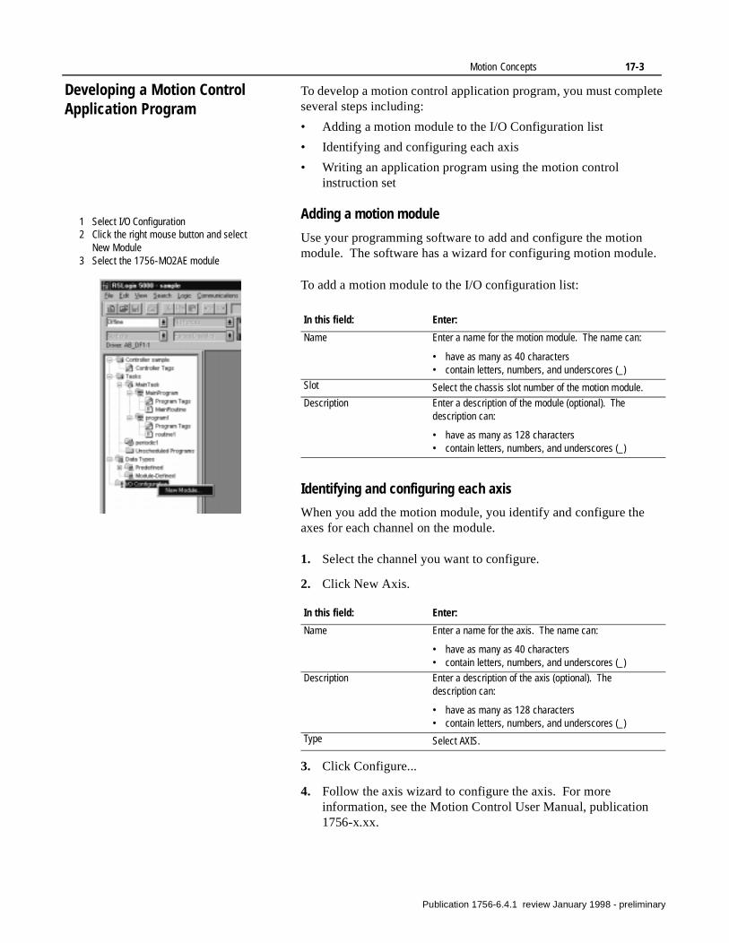
Motion Concepts 17-3
.
Developing a Motion Control Application Program
To develop a motion control application program, you must complete several steps including:
• Adding a motion module to the I/O Configuration list
• Identifying and configuring each axis
• Writing an application program using the motion control instruction set
Adding a motion module
Use your programming software to add and configure the motion module. The software has a wizard for configuring motion module
To add a motion module to the I/O configuration list:
Identifying and configuring each axis
When you add the motion module, you identify and configure the axes for each channel on the module.
1. Select the channel you want to configure.
2. Click New Axis.
3. Click Configure...
4. Follow the axis wizard to configure the axis. For more information, see the Motion Control User Manual, publication 1756-x.xx.
1 Select I/O Configuration2 Click the right mouse button and select
New Module3 Select the 1756-MO2AE module
In this field: Enter:
Name Enter a name for the motion module. The name can:
• have as many as 40 characters• contain letters, numbers, and underscores (_)
Slot Select the chassis slot number of the motion module.
Description Enter a description of the module (optional). The description can:
• have as many as 128 characters• contain letters, numbers, and underscores (_)
In this field: Enter:
Name Enter a name for the axis. The name can:
• have as many as 40 characters• contain letters, numbers, and underscores (_)
Description Enter a description of the axis (optional). The description can:
• have as many as 128 characters• contain letters, numbers, and underscores (_)
Type Select AXIS.
Publication 1756-6.4.1 review January 1998 - preliminary
17-4 Motion Concepts
Writing a motion application program
To write a motion application program, you can insert motion instructions directly into the ladder diagram application program.
The motion instruction set consists of five groups of motion instructions:
These instructions operate on one or more axes. You must identify and configure axes before you can use them. For more information about identifying and configuring axes, refer to the Motion Control User Manual, publication 1756-x.xx.
Group For more information, refer to:
Motion state instructions Chapter 18
Motion move instructions Chapter 19
Motion group instructions Chapter 20
Motion event instructions Chapter 21
Motion configuration instructions Chapter 22
Publication 1756-6.4.1 review January 1998 - preliminary
Motion Concepts 17-5
n.
er servo
se
ue,
Understanding Instruction Timing Motion instructions use three types of timing sequences:
• Immediate timing, where the instruction completes in one sca
• Delayed (message) timing, where the instruction completes ovseveral scans because the instruction sends messages to themodule.
• Process timing, where the instruction could take an indefinite amount of time to complete.
Immediate type instructions
Immediate type motion instructions execute to completion in one scan. If the processor detects an error during the execution of theinstructions, the error status bit sets and the operation ends.
Examples of immediate type instructions include the:
• Motion Change Dynamics (MCD) instruction
• Motion Group Strobe Position (MGSP) instruction
Immediate instructions work as follows:
1. When the rung that contains the motion instruction becomes trthe processor:
• Sets the enable (EN) bit.
• Clears the done (DN) bit.
• Clears the error (ER) bit.
2. The processor executes the instruction completely.
3.
4. The next time the rung becomes false, the processor clears the .EN bit.
If the processor: Then:
Does not detect an error when the instruction executes
The processor sets the .DN bit.
Detects an error when the instruction executes
The processor sets the .ER bit and stores an error code in the control structure.
Publication 1756-6.4.1 review January 1998 - preliminary
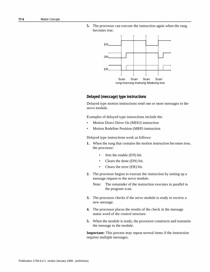
17-6 Motion Concepts
ue,
a
a
mits
n
5. The processor can execute the instruction again when the rung becomes true.
Delayed (message) type instructions
Delayed type motion instructions send one or more messages to the servo module.
Examples of delayed type instructions include the:
• Motion Direct Drive On (MDO) instruction
• Motion Redefine Position (MRP) instruction
Delayed type instructions work as follows:
1. When the rung that contains the motion instruction becomes trthe processor:
• Sets the enable (EN) bit.
• Clears the done (DN) bit.
• Clears the error (ER) bit.
2. The processor begins to execute the instruction by setting up message request to the servo module.
Note: The remainder of the instruction executes in parallel tothe program scan.
3. The processor checks if the servo module is ready to receive new message.
4. The processor places the results of the check in the messagestatus word of the control structure.
5. When the module is ready, the processor constructs and transthe message to the module.
Important: This process may repeat several times if the instructiorequires multiple messages.
EN
DN
ER
Scan rung true
Scan rung true
Scan rung false
Scan rung true
Publication 1756-6.4.1 review January 1998 - preliminary
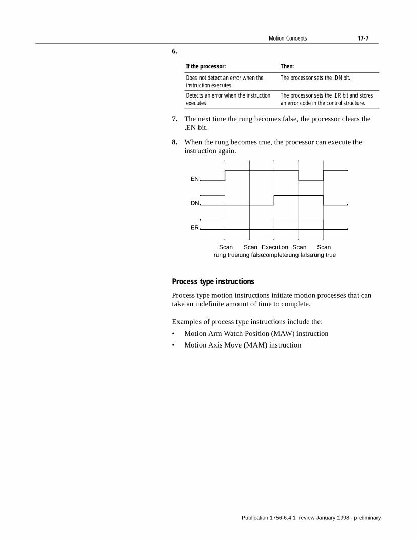
Motion Concepts 17-7
6.
7. The next time the rung becomes false, the processor clears the .EN bit.
8. When the rung becomes true, the processor can execute the instruction again.
Process type instructions
Process type motion instructions initiate motion processes that can take an indefinite amount of time to complete.
Examples of process type instructions include the:
• Motion Arm Watch Position (MAW) instruction
• Motion Axis Move (MAM) instruction
If the processor: Then:
Does not detect an error when the instruction executes
The processor sets the .DN bit.
Detects an error when the instruction executes
The processor sets the .ER bit and stores an error code in the control structure.
EN
DN
ER
Scan rung true
Scan rung true
Scan rung false
Scan rung false
Execution complete
Publication 1756-6.4.1 review January 1998 - preliminary
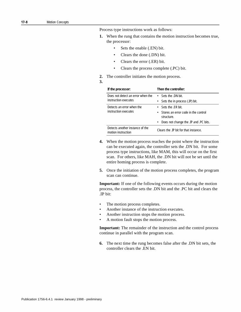
17-8 Motion Concepts
tion me
am
the
ss
e
Process type instructions work as follows:
1. When the rung that contains the motion instruction becomes true, the processor:
• Sets the enable (.EN) bit.
• Clears the done (.DN) bit.
• Clears the error (.ER) bit.
• Clears the process complete (.PC) bit.
2. The controller initiates the motion process.3.
4. When the motion process reaches the point where the instruccan be executed again, the controller sets the .DN bit. For soprocess type instructions, like MAM, this will occur on the firstscan. For others, like MAH, the .DN bit will not be set until theentire homing process is complete.
5. Once the initiation of the motion process completes, the progrscan can continue.
Important: If one of the following events occurs during the motionprocess, the controller sets the .DN bit and the .PC bit and clears.IP bit:
• The motion process completes.• Another instance of the instruction executes.• Another instruction stops the motion process.• A motion fault stops the motion process.
Important: The remainder of the instruction and the control procecontinue in parallel with the program scan.
6. The next time the rung becomes false after the .DN bit sets, thcontroller clears the .EN bit.
If the processor: Then the controller:
Does not detect an error when the instruction executes
• Sets the .DN bit.
• Sets the in process (.IP) bit.
Detects an error when the instruction executes
• Sets the .ER bit.
• Stores an error code in the control structure.
• Does not change the .IP and .PC bits.
Detects another instance of the motion instruction
Clears the .IP bit for that instance.
Publication 1756-6.4.1 review January 1998 - preliminary
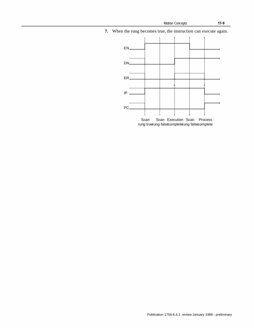
Motion Concepts 17-9
7. When the rung becomes true, the instruction can execute again.
EN
DN
ER
Scan rung true
Process complete
Scan rung false
Scan rung false
Execution complete
IP
PC
Publication 1756-6.4.1 review January 1998 - preliminary
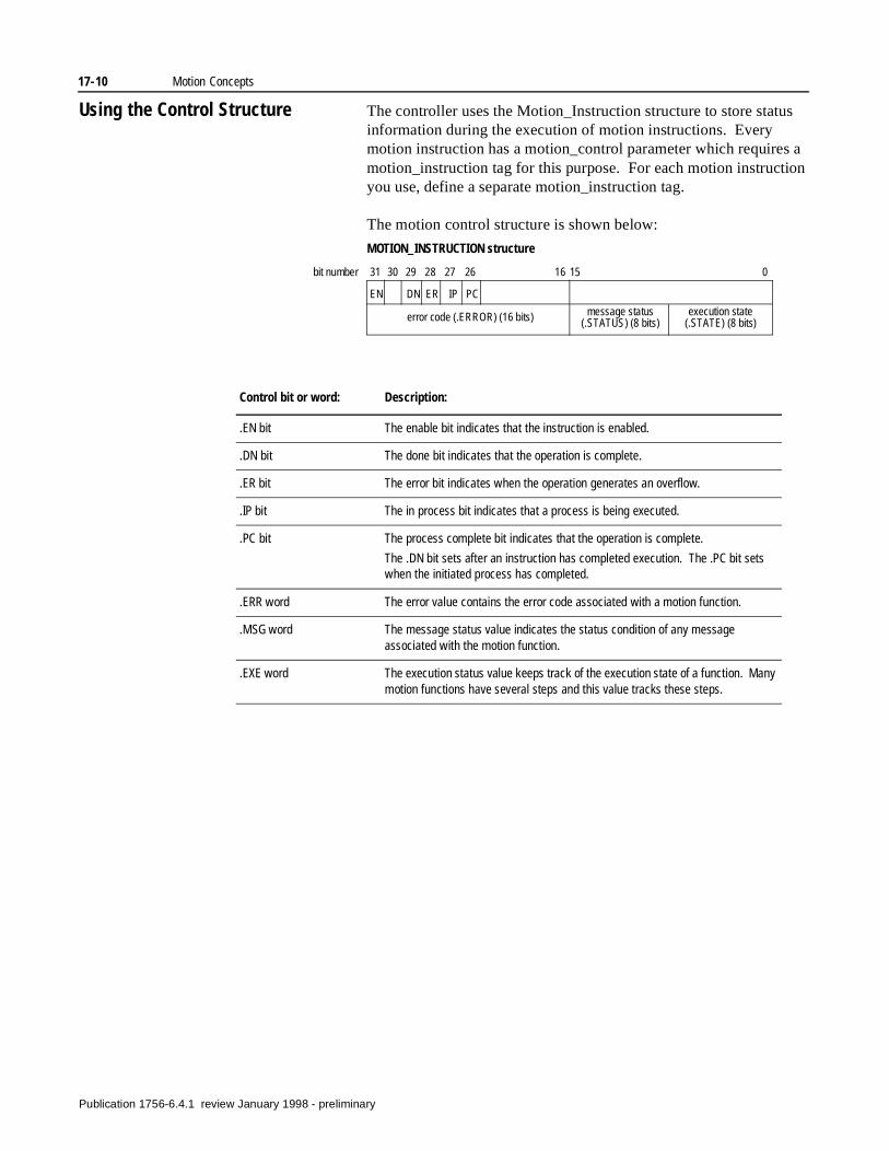
17-10 Motion Concepts
Using the Control Structure The controller uses the Motion_Instruction structure to store status information during the execution of motion instructions. Every motion instruction has a motion_control parameter which requires a motion_instruction tag for this purpose. For each motion instruction you use, define a separate motion_instruction tag.
The motion control structure is shown below:
MOTION_INSTRUCTION structure
EN DN ER
error code (.ERROR) (16 bits) message status (.STATUS) (8 bits)
execution state (.STATE) (8 bits)
IP PC
31 30 29 28 27 26 16 15 0bit number
Control bit or word: Description:
.EN bit The enable bit indicates that the instruction is enabled.
.DN bit The done bit indicates that the operation is complete.
.ER bit The error bit indicates when the operation generates an overflow.
.IP bit The in process bit indicates that a process is being executed.
.PC bit The process complete bit indicates that the operation is complete.
The .DN bit sets after an instruction has completed execution. The .PC bit sets when the initiated process has completed.
.ERR word The error value contains the error code associated with a motion function.
.MSG word The message status value indicates the status condition of any message associated with the motion function.
.EXE word The execution status value keeps track of the execution state of a function. Many motion functions have several steps and this value tracks these steps.
Publication 1756-6.4.1 review January 1998 - preliminary
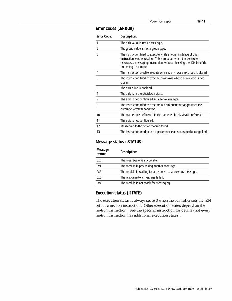
Motion Concepts 17-11
Error codes (.ERROR)
Message status (.STATUS)
Execution status (.STATE)
The execution status is always set to 0 when the controller sets the .EN bit for a motion instruction. Other execution states depend on the motion instruction. See the specific instruction for details (not every motion instruction has additional execution states).
Error Code: Description:
1 The axis value is not an axis type.
2 The group value is not a group type.
3 The instruction tried to execute while another instance of this instruction was executing. This can occur when the controller executes a messaging instruction without checking the .DN bit of the preceding instruction.
4 The instruction tried to execute on an axis whose servo loop is closed.
5 The instruction tried to execute on an axis whose servo loop is not closed.
6 The axis drive is enabled.
7 The axis is in the shutdown state.
8 The axis is not configured as a servo axis type.
9 The instruction tried to execute in a direction that aggravates the current overtravel condition.
10 The master axis reference is the same as the slave axis reference.
11 The axis is not configured.
12 Messaging to the servo module failed.
13 The instruction tried to use a parameter that is outside the range limit.
Message Status:
Description:
0x0 The message was successful.
0x1 The module is processing another message.
0x2 The module is waiting for a response to a previous message.
0x3 The response to a message failed.
0x4 The module is not ready for messaging.
Publication 1756-6.4.1 review January 1998 - preliminary
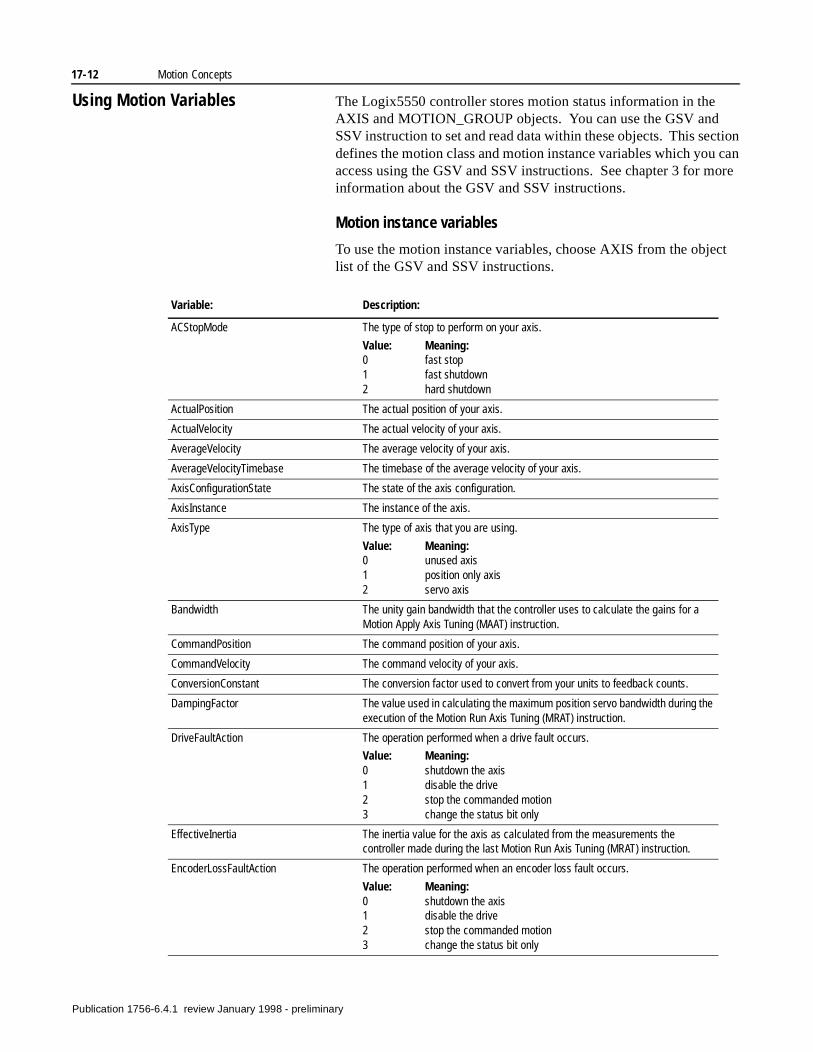
17-12 Motion Concepts
Using Motion Variables The Logix5550 controller stores motion status information in the AXIS and MOTION_GROUP objects. You can use the GSV and SSV instruction to set and read data within these objects. This section defines the motion class and motion instance variables which you can access using the GSV and SSV instructions. See chapter 3 for more information about the GSV and SSV instructions.
Motion instance variables
To use the motion instance variables, choose AXIS from the object list of the GSV and SSV instructions.
Variable: Description:
ACStopMode The type of stop to perform on your axis.
Value: Meaning:0 fast stop1 fast shutdown2 hard shutdown
ActualPosition The actual position of your axis.
ActualVelocity The actual velocity of your axis.
AverageVelocity The average velocity of your axis.
AverageVelocityTimebase The timebase of the average velocity of your axis.
AxisConfigurationState The state of the axis configuration.
AxisInstance The instance of the axis.
AxisType The type of axis that you are using.
Value: Meaning:0 unused axis1 position only axis2 servo axis
Bandwidth The unity gain bandwidth that the controller uses to calculate the gains for a Motion Apply Axis Tuning (MAAT) instruction.
CommandPosition The command position of your axis.
CommandVelocity The command velocity of your axis.
ConversionConstant The conversion factor used to convert from your units to feedback counts.
DampingFactor The value used in calculating the maximum position servo bandwidth during the execution of the Motion Run Axis Tuning (MRAT) instruction.
DriveFaultAction The operation performed when a drive fault occurs.
Value: Meaning:0 shutdown the axis1 disable the drive2 stop the commanded motion3 change the status bit only
EffectiveInertia The inertia value for the axis as calculated from the measurements the controller made during the last Motion Run Axis Tuning (MRAT) instruction.
EncoderLossFaultAction The operation performed when an encoder loss fault occurs.
Value: Meaning:0 shutdown the axis1 disable the drive2 stop the commanded motion3 change the status bit only
Publication 1756-6.4.1 review January 1998 - preliminary
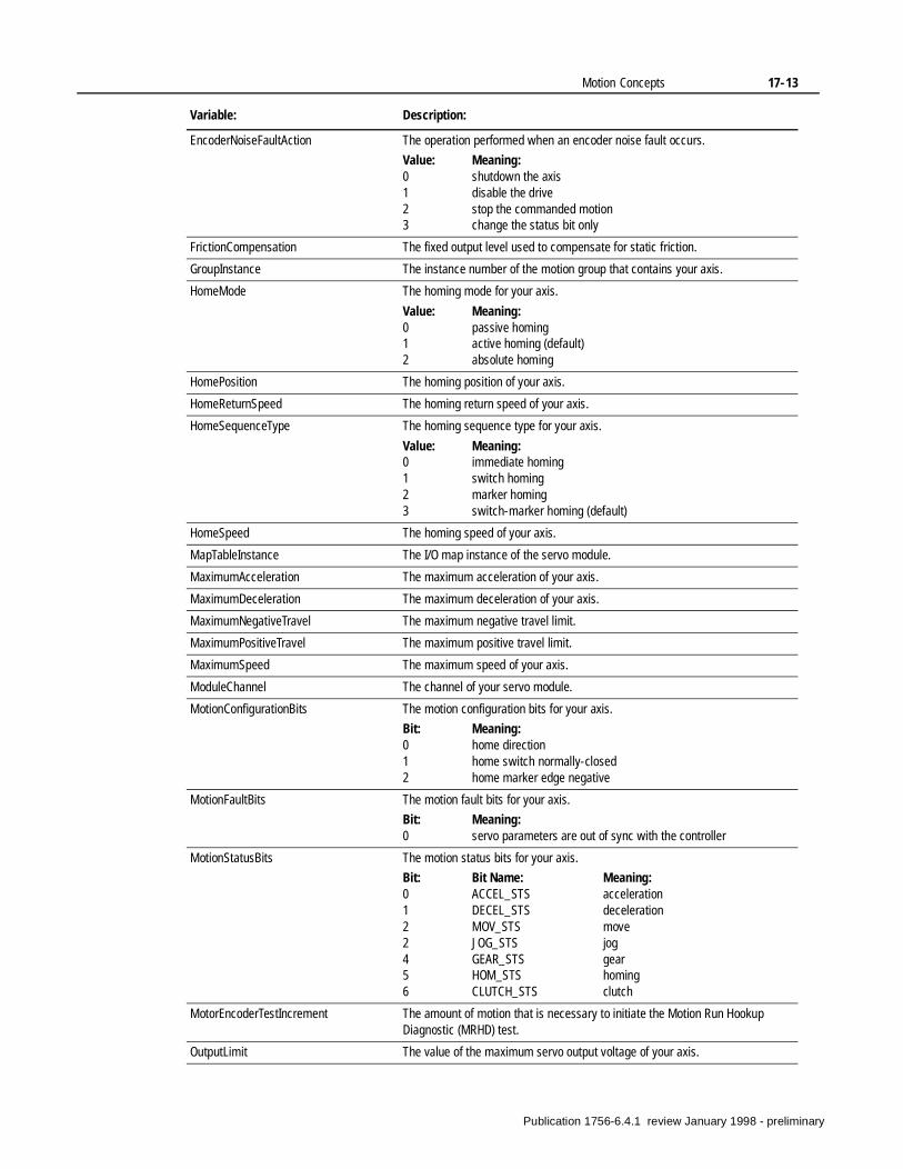
Motion Concepts 17-13
EncoderNoiseFaultAction The operation performed when an encoder noise fault occurs.
Value: Meaning:0 shutdown the axis1 disable the drive2 stop the commanded motion3 change the status bit only
FrictionCompensation The fixed output level used to compensate for static friction.
GroupInstance The instance number of the motion group that contains your axis.
HomeMode The homing mode for your axis.
Value: Meaning:0 passive homing1 active homing (default)2 absolute homing
HomePosition The homing position of your axis.
HomeReturnSpeed The homing return speed of your axis.
HomeSequenceType The homing sequence type for your axis.
Value: Meaning:0 immediate homing1 switch homing2 marker homing3 switch-marker homing (default)
HomeSpeed The homing speed of your axis.
MapTableInstance The I/O map instance of the servo module.
MaximumAcceleration The maximum acceleration of your axis.
MaximumDeceleration The maximum deceleration of your axis.
MaximumNegativeTravel The maximum negative travel limit.
MaximumPositiveTravel The maximum positive travel limit.
MaximumSpeed The maximum speed of your axis.
ModuleChannel The channel of your servo module.
MotionConfigurationBits The motion configuration bits for your axis.
Bit: Meaning:0 home direction1 home switch normally-closed2 home marker edge negative
MotionFaultBits The motion fault bits for your axis.
Bit: Meaning:0 servo parameters are out of sync with the controller
MotionStatusBits The motion status bits for your axis.
Bit: Bit Name: Meaning:0 ACCEL_STS acceleration1 DECEL_STS deceleration2 MOV_STS move2 JOG_STS jog4 GEAR_STS gear5 HOM_STS homing6 CLUTCH_STS clutch
MotorEncoderTestIncrement The amount of motion that is necessary to initiate the Motion Run Hookup Diagnostic (MRHD) test.
OutputLimit The value of the maximum servo output voltage of your axis.
Variable: Description:
Publication 1756-6.4.1 review January 1998 - preliminary
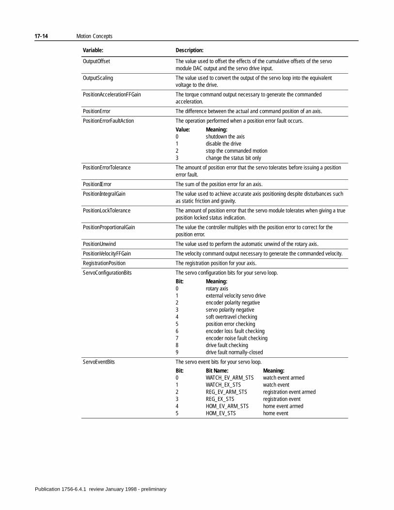
17-14 Motion Concepts
OutputOffset The value used to offset the effects of the cumulative offsets of the servo module DAC output and the servo drive input.
OutputScaling The value used to convert the output of the servo loop into the equivalent voltage to the drive.
PositionAccelerationFFGain The torque command output necessary to generate the commanded acceleration.
PositionError The difference between the actual and command position of an axis.
PositionErrorFaultAction The operation performed when a position error fault occurs.
Value: Meaning:0 shutdown the axis1 disable the drive2 stop the commanded motion3 change the status bit only
PositionErrorTolerance The amount of position error that the servo tolerates before issuing a position error fault.
PositionIError The sum of the position error for an axis.
PositionIntegralGain The value used to achieve accurate axis positioning despite disturbances such as static friction and gravity.
PositionLockTolerance The amount of position error that the servo module tolerates when giving a true position locked status indication.
PositionProportionalGain The value the controller multiples with the position error to correct for the position error.
PositionUnwind The value used to perform the automatic unwind of the rotary axis.
PositionVelocityFFGain The velocity command output necessary to generate the commanded velocity.
RegistrationPosition The registration position for your axis.
ServoConfigurationBits The servo configuration bits for your servo loop.
Bit: Meaning:0 rotary axis1 external velocity servo drive2 encoder polarity negative3 servo polarity negative4 soft overtravel checking5 position error checking6 encoder loss fault checking7 encoder noise fault checking8 drive fault checking9 drive fault normally-closed
ServoEventBits The servo event bits for your servo loop.
Bit: Bit Name: Meaning:0 WATCH_EV_ARM_STS watch event armed1 WATCH_EX_STS watch event2 REG_EV_ARM_STS registration event armed3 REG_EX_STS registration event4 HOM_EV_ARM_STS home event armed5 HOM_EV_STS home event
Variable: Description:
Publication 1756-6.4.1 review January 1998 - preliminary
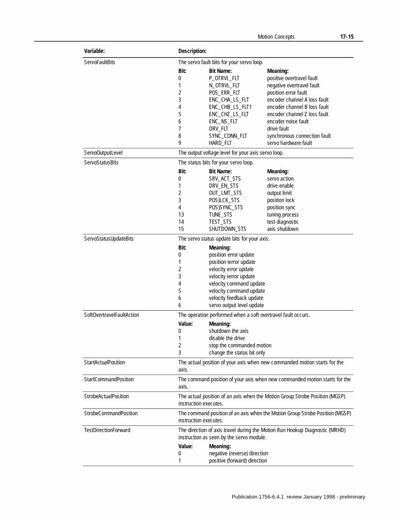
Motion Concepts 17-15
ServoFaultBits The servo fault bits for your servo loop.
Bit: Bit Name: Meaning:0 P_OTRVL_FLT positive overtravel fault1 N_OTRVL_FLT negative overtravel fault2 POS_ERR_FLT position error fault3 ENC_CHA_LS_FLT encoder channel A loss fault4 ENC_CHB_LS_FLT1 encoder channel B loss fault5 ENC_CHZ_LS_FLT encoder channel Z loss fault6 ENC_NS_FLT encoder noise fault7 DRV_FLT drive fault8 SYNC_CONN_FLT synchronous connection fault9 HARD_FLT servo hardware fault
ServoOutputLevel The output voltage level for your axis servo loop.
ServoStatusBits The status bits for your servo loop.
Bit: Bit Name: Meaning:0 SRV_ACT_STS servo action1 DRV_EN_STS drive enable2 OUT_LMT_STS output limit3 POS)LCK_STS position lock4 POS)SYNC_STS position sync13 TUNE_STS tuning process14 TEST_STS test diagnostic15 SHUTDOWN_STS axis shutdown
ServoStatusUpdateBits The servo status update bits for your axis.
Bit: Meaning:0 position error update1 position ierror update2 velocity error update3 velocity ierror update4 velocity command update5 velocity command update6 velocity feedback update6 servo output level update
SoftOvertravelFaultAction The operation performed when a soft overtravel fault occurs.
Value: Meaning:0 shutdown the axis1 disable the drive2 stop the commanded motion3 change the status bit only
StartActualPosition The actual position of your axis when new commanded motion starts for the axis.
StartCommandPosition The command position of your axis when new commanded motion starts for the axis.
StrobeActualPosition The actual position of an axis when the Motion Group Strobe Position (MGSP) instruction executes.
StrobeCommandPosition The command position of an axis when the Motion Group Strobe Position (MGSP) instruction executes.
TestDirectionForward The direction of axis travel during the Motion Run Hookup Diagnostic (MRHD) instruction as seen by the servo module.
Value: Meaning:0 negative (reverse) direction1 positive (forward) direction
Variable: Description:
Publication 1756-6.4.1 review January 1998 - preliminary
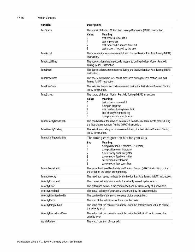
17-16 Motion Concepts
TestStatus The status of the last Motion Run Hookup Diagnostic (MRHD) instruction.
Value: Meaning:0 test process successful1 test in progress2 test exceeded 2-second time-out3 test process stopped by the user
TuneAccel The acceleration value measured during the last Motion Run Axis Tuning (MRAT) instruction.
TuneAccelTime The acceleration time in seconds measured during the last Motion Run Axis Tuning (MRAT) instruction.
TuneDecel The deceleration value measured during the last Motion Run Axis Tuning (MRAT) instruction.
TuneDecelTime The deceleration time in seconds measured during the last Motion Run Axis Tuning (MRAT) instruction.
TuneRiseTime The axis rise time in seconds measured during the last Motion Run Axis Tuning (MRAT) instruction.
TuneStatus The status of the last Motion Run Axis Tuning (MRAT) instruction.
Value: Meaning:0 test process successful1 tuning in progress2 axis reached tuning travel limit3 axis polarity set incorrectly4 tune process aborted by user
TuneVelocityBandwidth The bandwidth of the drive as calculated from the measurements made during the last Motion Run Axis Tuning (MRAT) instruction.
TuneVelocityScaling The axis drive scaling factor measured during the last Motion Run Axis Tuning (MRAT) instruction.
TuningConfigurationBits The tuning configuration bits for your axis.
Bit: Meaning:0 tuning direction (0=forward, 1=reverse)1 tune position error integrator2 tune velocity error integrator3 tune velocity feedforward bit4 acceleration feedforward5 tune velocity low-pass filter
TuningTravelLimit The travel limit used by the Motion Run Axis Tuning (MRAT) instruction to limit the action of the action during tuning.
TuningVelocity The maximum speed initiated by the Motion Run Axis Tuning (MRAT) instruction.
VelocityCommand The current velocity reference to the velocity servo loop for an axis.
VelocityError The difference between the commanded and actual velocity of a servo axis.
VelocityFeedback The actual velocity of your axis as estimated by the servo module.
VelocityFilterBandwidth The bandwidth of the servo low-pass digital output filter.
VelocityIError The sum of the velocity error for a specified axis.
VelocityIntegralGain The value that the controller multiplies with the Velocity IError value to correct the velocity error.
VelocityProportionalGain The value that the controller multiplies with the Velocity Error to correct the velocity error.
WatchPosition The watch position of your axis.
Variable: Description:
Publication 1756-6.4.1 review January 1998 - preliminary
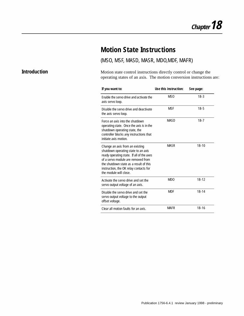
Chapter18
Motion State Instructions(MSO, MSF, MASD, MASR, MDO,MDF, MAFR)
Introduction Motion state control instructions directly control or change the operating states of an axis. The motion conversion instructions are:
If you want to: Use this instruction: See page:
Enable the servo drive and activate the axis servo loop.
MSO 18-3
Disable the servo drive and deactivate the axis servo loop.
MSF 18-5
Force an axis into the shutdown operating state. Once the axis is in the shutdown operating state, the controller blocks any instructions that initiate axis motion.
MASD 18-7
Change an axis from an existing shutdown operating state to an axis ready operating state. If all of the axes of a servo module are removed from the shutdown state as a result of this instruction, the OK relay contacts for the module will close.
MASR 18-10
Activate the servo drive and set the servo output voltage of an axis.
MDO 18-12
Disable the servo drive and set the servo output voltage to the output offset voltage.
MDF 18-14
Clear all motion faults for an axis. MAFR 18-16
Publication 1756-6.4.1 review January 1998 - preliminary
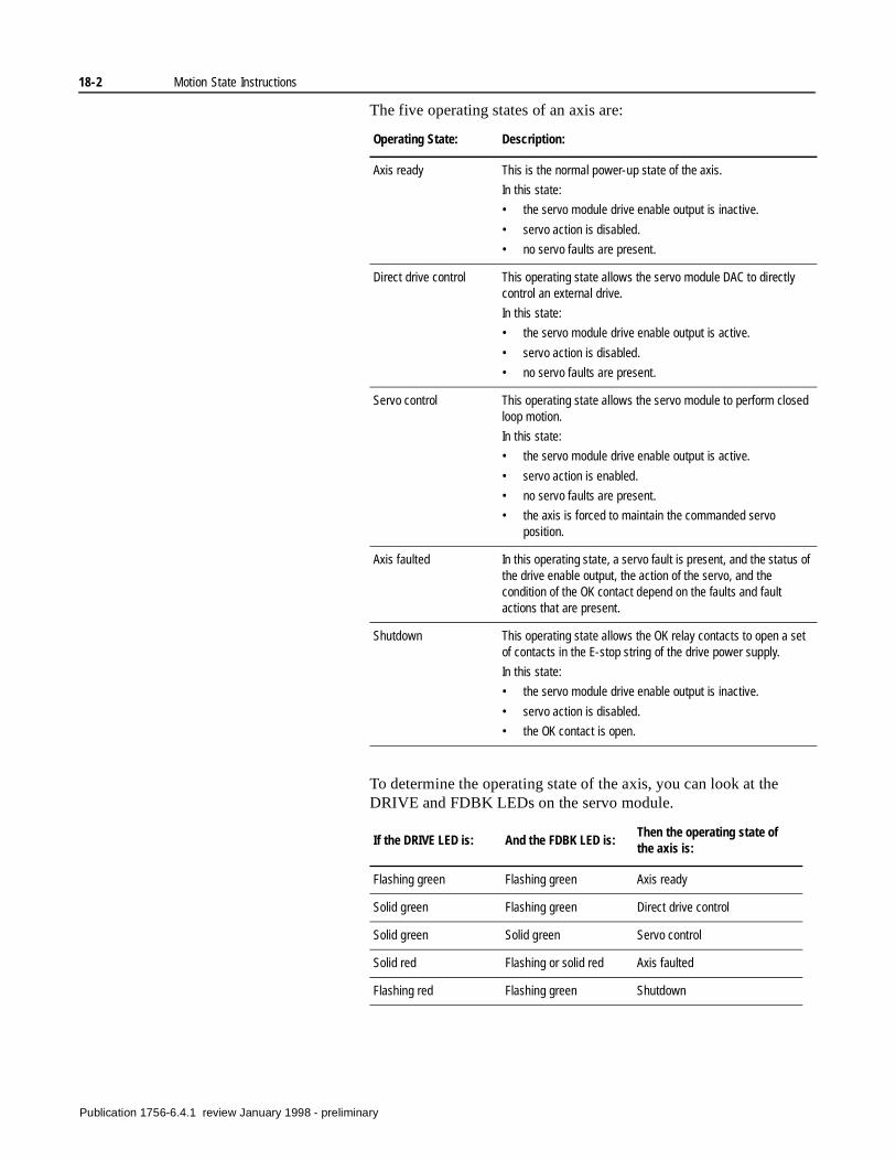
18-2 Motion State Instructions
The five operating states of an axis are:
To determine the operating state of the axis, you can look at the DRIVE and FDBK LEDs on the servo module.
Operating State: Description:
Axis ready This is the normal power-up state of the axis.
In this state:
• the servo module drive enable output is inactive.
• servo action is disabled.
• no servo faults are present.
Direct drive control This operating state allows the servo module DAC to directly control an external drive.
In this state:
• the servo module drive enable output is active.
• servo action is disabled.
• no servo faults are present.
Servo control This operating state allows the servo module to perform closed loop motion.
In this state:
• the servo module drive enable output is active.
• servo action is enabled.
• no servo faults are present.
• the axis is forced to maintain the commanded servo position.
Axis faulted In this operating state, a servo fault is present, and the status of the drive enable output, the action of the servo, and the condition of the OK contact depend on the faults and fault actions that are present.
Shutdown This operating state allows the OK relay contacts to open a set of contacts in the E-stop string of the drive power supply.
In this state:
• the servo module drive enable output is inactive.
• servo action is disabled.
• the OK contact is open.
If the DRIVE LED is: And the FDBK LED is:Then the operating state of the axis is:
Flashing green Flashing green Axis ready
Solid green Flashing green Direct drive control
Solid green Solid green Servo control
Solid red Flashing or solid red Axis faulted
Flashing red Flashing green Shutdown
Publication 1756-6.4.1 review January 1998 - preliminary
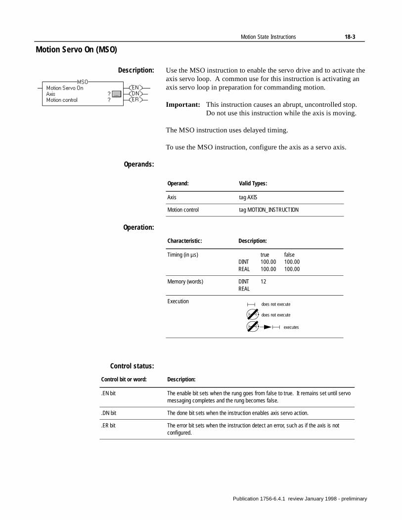
Motion State Instructions 18-3
Motion Servo On (MSO)
Description: Use the MSO instruction to enable the servo drive and to activate the axis servo loop. A common use for this instruction is activating an axis servo loop in preparation for commanding motion.
Important: This instruction causes an abrupt, uncontrolled stop. Do not use this instruction while the axis is moving.
The MSO instruction uses delayed timing.
To use the MSO instruction, configure the axis as a servo axis.
Operands:
Operation:
Control status:
Operand: Valid Types:
Axis tag AXIS
Motion control tag MOTION_INSTRUCTION
Characteristic: Description:
Timing (in µs) true falseDINT 100.00 100.00REAL 100.00 100.00
Memory (words) DINT 12REAL
Execution does not execute
does not execute
executes
Control bit or word: Description:
.EN bit The enable bit sets when the rung goes from false to true. It remains set until servo messaging completes and the rung becomes false.
.DN bit The done bit sets when the instruction enables axis servo action.
.ER bit The error bit sets when the instruction detect an error, such as if the axis is not configured.
Publication 1756-6.4.1 review January 1998 - preliminary
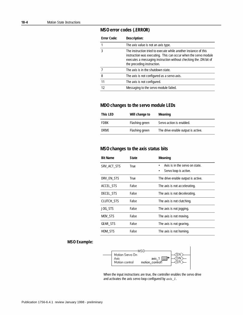
18-4 Motion State Instructions
MSO error codes (.ERROR)
MDO changes to the servo module LEDs
MSO changes to the axis status bits
MSO Example:
Error Code: Description:
1 The axis value is not an axis type.
3 The instruction tried to execute while another instance of this instruction was executing. This can occur when the servo module executes a messaging instruction without checking the .DN bit of the preceding instruction.
7 The axis is in the shutdown state.
8 The axis is not configured as a servo axis.
11 The axis is not configured.
12 Messaging to the servo module failed.
This LED Will change to Meaning
FDBK Flashing green Servo action is enabled.
DRIVE Flashing green The drive enable output is active.
Bit Name State Meaning
SRV_ACT_STS True • Axis is in the servo on state.
• Servo loop is active.
DRV_EN_STS True The drive enable output is active.
ACCEL_STS False The axis is not accelerating.
DECEL_STS False The axis is not decelerating.
CLUTCH_STS False The axis is not clutching.
JOG_STS False The axis is not jogging.
MOV_STS False The axis is not moving.
GEAR_STS False The axis is not gearing.
HOM_STS False The axis is not homing.
When the input instructions are true, the controller enables the servo drive and activates the axis servo loop configured by axis_1.
Publication 1756-6.4.1 review January 1998 - preliminary
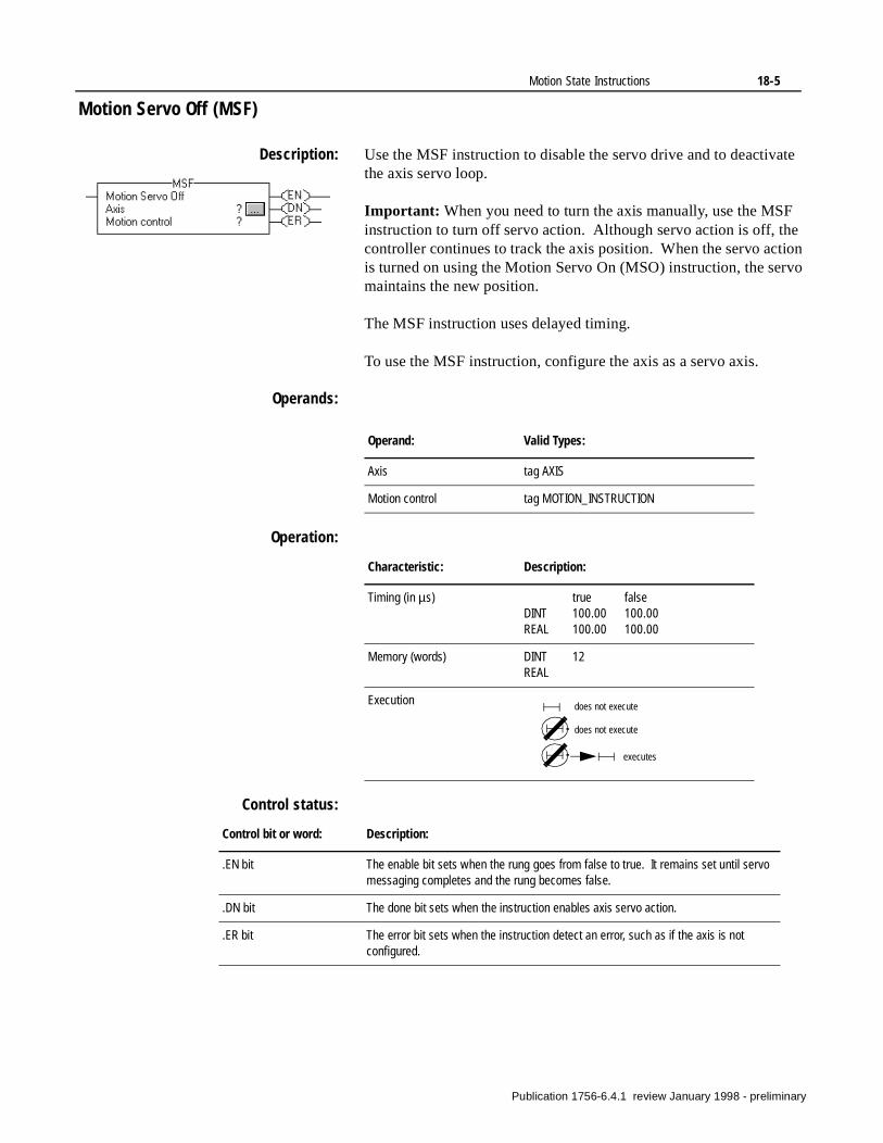
Motion State Instructions 18-5
Motion Servo Off (MSF)
Description: Use the MSF instruction to disable the servo drive and to deactivate the axis servo loop.
Important: When you need to turn the axis manually, use the MSF instruction to turn off servo action. Although servo action is off, the controller continues to track the axis position. When the servo action is turned on using the Motion Servo On (MSO) instruction, the servo maintains the new position.
The MSF instruction uses delayed timing.
To use the MSF instruction, configure the axis as a servo axis.
Operands:
Operation:
Control status:
Operand: Valid Types:
Axis tag AXIS
Motion control tag MOTION_INSTRUCTION
Characteristic: Description:
Timing (in µs) true falseDINT 100.00 100.00REAL 100.00 100.00
Memory (words) DINT 12REAL
Execution does not execute
does not execute
executes
Control bit or word: Description:
.EN bit The enable bit sets when the rung goes from false to true. It remains set until servo messaging completes and the rung becomes false.
.DN bit The done bit sets when the instruction enables axis servo action.
.ER bit The error bit sets when the instruction detect an error, such as if the axis is not configured.
Publication 1756-6.4.1 review January 1998 - preliminary
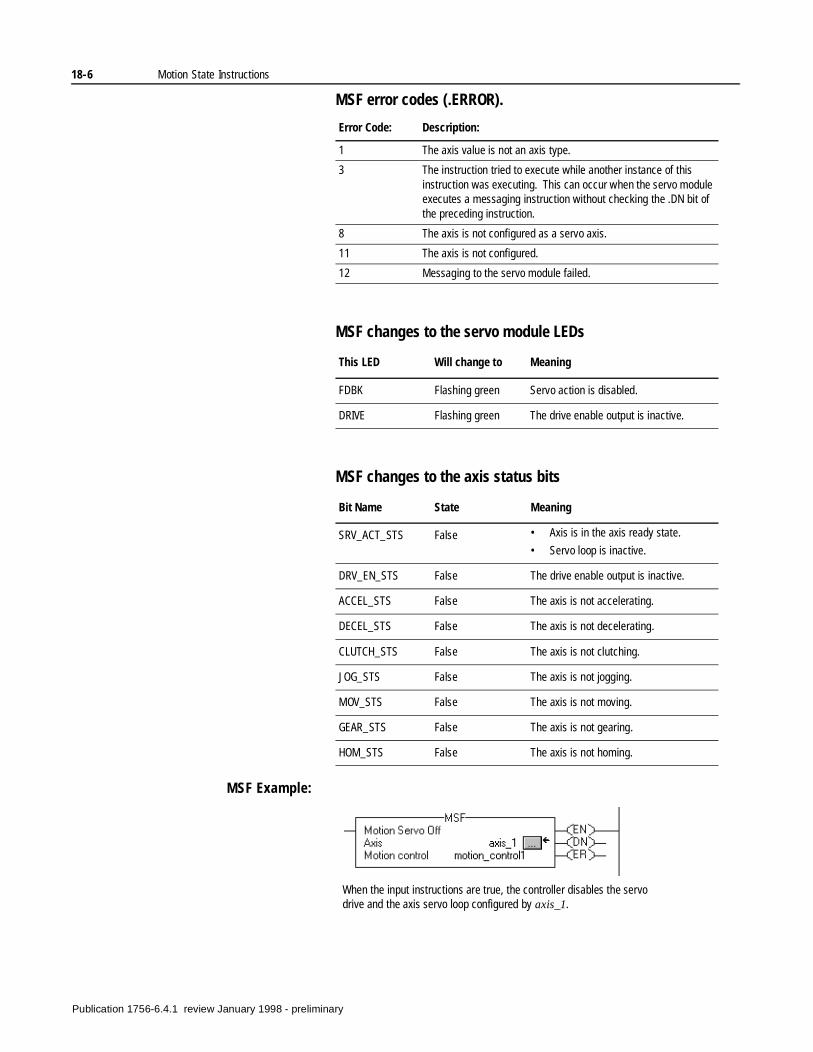
18-6 Motion State Instructions
MSF error codes (.ERROR).
MSF changes to the servo module LEDs
MSF changes to the axis status bits
MSF Example:
Error Code: Description:
1 The axis value is not an axis type.
3 The instruction tried to execute while another instance of this instruction was executing. This can occur when the servo module executes a messaging instruction without checking the .DN bit of the preceding instruction.
8 The axis is not configured as a servo axis.
11 The axis is not configured.
12 Messaging to the servo module failed.
This LED Will change to Meaning
FDBK Flashing green Servo action is disabled.
DRIVE Flashing green The drive enable output is inactive.
Bit Name State Meaning
SRV_ACT_STS False • Axis is in the axis ready state.
• Servo loop is inactive.
DRV_EN_STS False The drive enable output is inactive.
ACCEL_STS False The axis is not accelerating.
DECEL_STS False The axis is not decelerating.
CLUTCH_STS False The axis is not clutching.
JOG_STS False The axis is not jogging.
MOV_STS False The axis is not moving.
GEAR_STS False The axis is not gearing.
HOM_STS False The axis is not homing.
When the input instructions are true, the controller disables the servo drive and the axis servo loop configured by axis_1.
Publication 1756-6.4.1 review January 1998 - preliminary
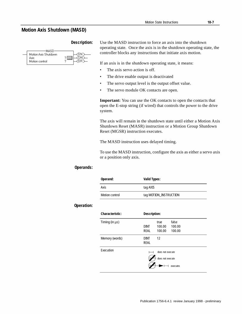
Motion State Instructions 18-7
t e
is
xis
Motion Axis Shutdown (MASD)
Description: Use the MASD instruction to force an axis into the shutdown operating state. Once the axis is in the shutdown operating state, the controller blocks any instructions that initiate axis motion.
If an axis is in the shutdown operating state, it means:
• The axis servo action is off.
• The drive enable output is deactivated
• The servo output level is the output offset value.
• The servo module OK contacts are open.
Important: You can use the OK contacts to open the contacts thaopen the E-stop string (if wired) that controls the power to the drivsystem.
The axis will remain in the shutdown state until either a Motion AxShutdown Reset (MASR) instruction or a Motion Group ShutdownReset (MGSR) instruction executes.
The MASD instruction uses delayed timing.
To use the MASD instruction, configure the axis as either a servo aor a position only axis.
Operands:
Operation:
Operand: Valid Types:
Axis tag AXIS
Motion control tag MOTION_INSTRUCTION
Characteristic: Description:
Timing (in µs) true falseDINT 100.00 100.00REAL 100.00 100.00
Memory (words) DINT 12REAL
Execution does not execute
does not execute
executes
Publication 1756-6.4.1 review January 1998 - preliminary
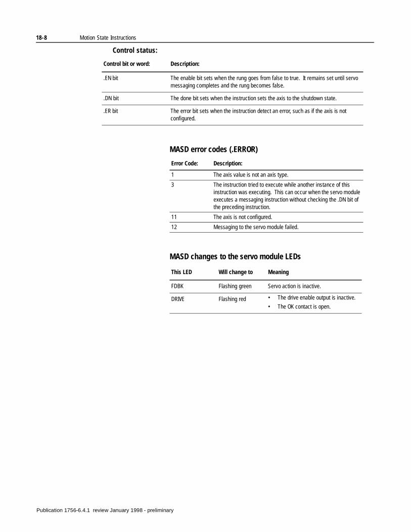
18-8 Motion State Instructions
Control status:
MASD error codes (.ERROR)
MASD changes to the servo module LEDs
Control bit or word: Description:
.EN bit The enable bit sets when the rung goes from false to true. It remains set until servo messaging completes and the rung becomes false.
.DN bit The done bit sets when the instruction sets the axis to the shutdown state.
.ER bit The error bit sets when the instruction detect an error, such as if the axis is not configured.
Error Code: Description:
1 The axis value is not an axis type.
3 The instruction tried to execute while another instance of this instruction was executing. This can occur when the servo module executes a messaging instruction without checking the .DN bit of the preceding instruction.
11 The axis is not configured.
12 Messaging to the servo module failed.
This LED Will change to Meaning
FDBK Flashing green Servo action is inactive.
DRIVE Flashing red • The drive enable output is inactive.
• The OK contact is open.
Publication 1756-6.4.1 review January 1998 - preliminary
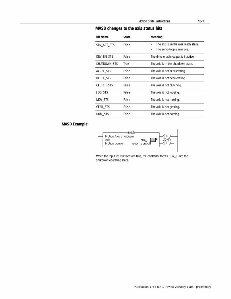
Motion State Instructions 18-9
MASD changes to the axis status bits
MASD Example:
Bit Name State Meaning
SRV_ACT_STS False • The axis is in the axis ready state.
• The servo loop is inactive.
DRV_EN_STS False The drive enable output is inactive.
SHUTDOWN_STS True The axis is in the shutdown state.
ACCEL_STS False The axis is not accelerating.
DECEL_STS False The axis is not decelerating.
CLUTCH_STS False The axis is not clutching.
JOG_STS False The axis is not jogging.
MOV_STS False The axis is not moving.
GEAR_STS False The axis is not gearing.
HOM_STS False The axis is not homing.
When the input instructions are true, the controller forces axis_1 into the shutdown operating state.
Publication 1756-6.4.1 review January 1998 - preliminary
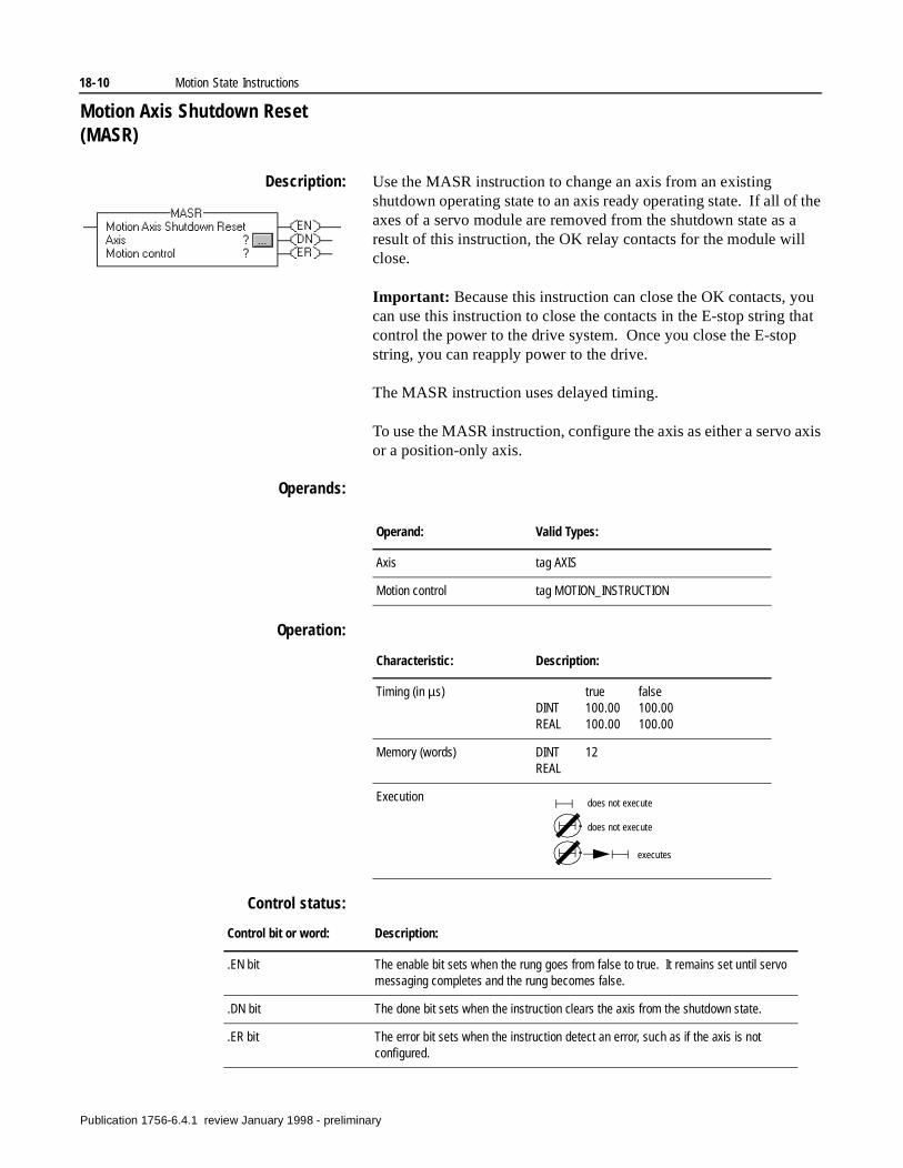
18-10 Motion State Instructions
Motion Axis Shutdown Reset (MASR)
Description: Use the MASR instruction to change an axis from an existing shutdown operating state to an axis ready operating state. If all of the axes of a servo module are removed from the shutdown state as a result of this instruction, the OK relay contacts for the module will close.
Important: Because this instruction can close the OK contacts, you can use this instruction to close the contacts in the E-stop string that control the power to the drive system. Once you close the E-stop string, you can reapply power to the drive.
The MASR instruction uses delayed timing.
To use the MASR instruction, configure the axis as either a servo axis or a position-only axis.
Operands:
Operation:
Control status:
Operand: Valid Types:
Axis tag AXIS
Motion control tag MOTION_INSTRUCTION
Characteristic: Description:
Timing (in µs) true falseDINT 100.00 100.00REAL 100.00 100.00
Memory (words) DINT 12REAL
Execution does not execute
does not execute
executes
Control bit or word: Description:
.EN bit The enable bit sets when the rung goes from false to true. It remains set until servo messaging completes and the rung becomes false.
.DN bit The done bit sets when the instruction clears the axis from the shutdown state.
.ER bit The error bit sets when the instruction detect an error, such as if the axis is not configured.
Publication 1756-6.4.1 review January 1998 - preliminary
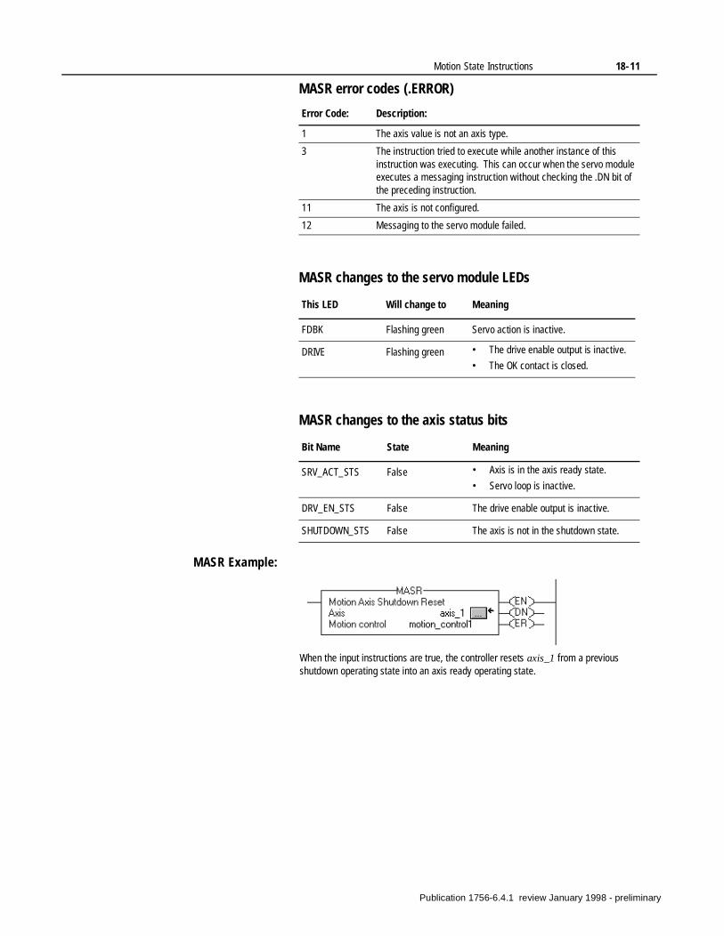
Motion State Instructions 18-11
MASR error codes (.ERROR)
MASR changes to the servo module LEDs
MASR changes to the axis status bits
MASR Example:
Error Code: Description:
1 The axis value is not an axis type.
3 The instruction tried to execute while another instance of this instruction was executing. This can occur when the servo module executes a messaging instruction without checking the .DN bit of the preceding instruction.
11 The axis is not configured.
12 Messaging to the servo module failed.
This LED Will change to Meaning
FDBK Flashing green Servo action is inactive.
DRIVE Flashing green • The drive enable output is inactive.
• The OK contact is closed.
Bit Name State Meaning
SRV_ACT_STS False • Axis is in the axis ready state.
• Servo loop is inactive.
DRV_EN_STS False The drive enable output is inactive.
SHUTDOWN_STS False The axis is not in the shutdown state.
When the input instructions are true, the controller resets axis_1 from a previous shutdown operating state into an axis ready operating state.
Publication 1756-6.4.1 review January 1998 - preliminary
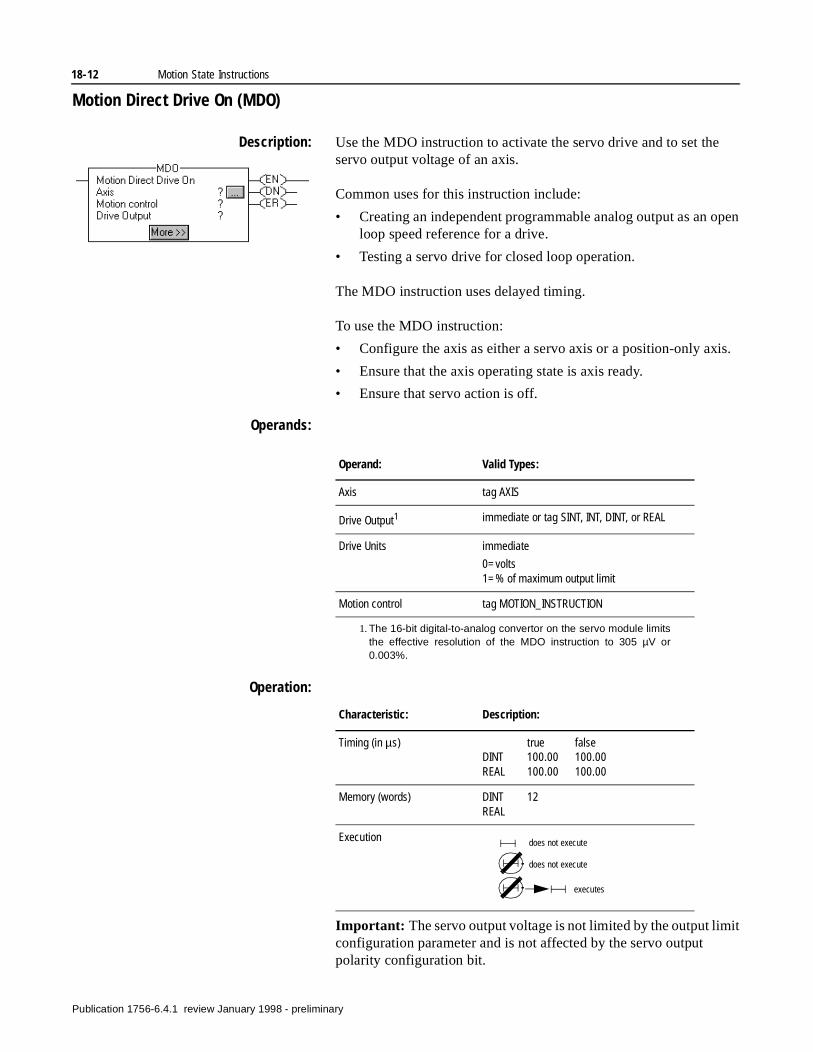
18-12 Motion State Instructions
pen
s.
it
Motion Direct Drive On (MDO)
Description: Use the MDO instruction to activate the servo drive and to set the servo output voltage of an axis.
Common uses for this instruction include:
• Creating an independent programmable analog output as an oloop speed reference for a drive.
• Testing a servo drive for closed loop operation.
The MDO instruction uses delayed timing.
To use the MDO instruction:
• Configure the axis as either a servo axis or a position-only axi
• Ensure that the axis operating state is axis ready.
• Ensure that servo action is off.
Operands:
Operation:
Important: The servo output voltage is not limited by the output limconfiguration parameter and is not affected by the servo output polarity configuration bit.
Operand: Valid Types:
Axis tag AXIS
Drive Output1
1. The 16-bit digital-to-analog convertor on the servo module limitsthe effective resolution of the MDO instruction to 305 µV or0.003%.
immediate or tag SINT, INT, DINT, or REAL
Drive Units immediate
0=volts 1=% of maximum output limit
Motion control tag MOTION_INSTRUCTION
Characteristic: Description:
Timing (in µs) true falseDINT 100.00 100.00REAL 100.00 100.00
Memory (words) DINT 12REAL
Execution does not execute
does not execute
executes
Publication 1756-6.4.1 review January 1998 - preliminary
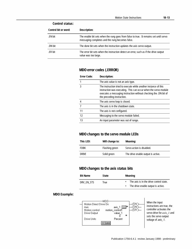
Motion State Instructions 18-13
Control status:
MDO error codes (.ERROR)
MDO changes to the servo module LEDs
MDO changes to the axis status bits
MDO Example:
Control bit or word: Description:
.EN bit The enable bit sets when the rung goes from false to true. It remains set until servo messaging completes and the rung becomes false.
.DN bit The done bit sets when the instruction updates the axis servo output.
.ER bit The error bit sets when the instruction detect an error, such as if the drive output value was too large.
Error Code: Description:
1 The axis value is not an axis type.
3 The instruction tried to execute while another instance of this instruction was executing. This can occur when the servo module executes a messaging instruction without checking the .DN bit of the preceding instruction.
4 The axis servo loop is closed.
7 The axis is in the shutdown state.
11 The axis is not configured.
12 Messaging to the servo module failed.
13 An input parameter was out of range.
This LED: Will change to: Meaning:
FDBK Flashing green Servo action is disabled.
DRIVE Solid green The drive enable output is active.
Bit Name State Meaning
DRV_EN_STS True • The axis is in the drive control state.
• The drive enable output is active.
When the input instructions are true, the controller activates the servo drive for axis_1 and sets the servo output voltage of axis_1.
Publication 1756-6.4.1 review January 1998 - preliminary
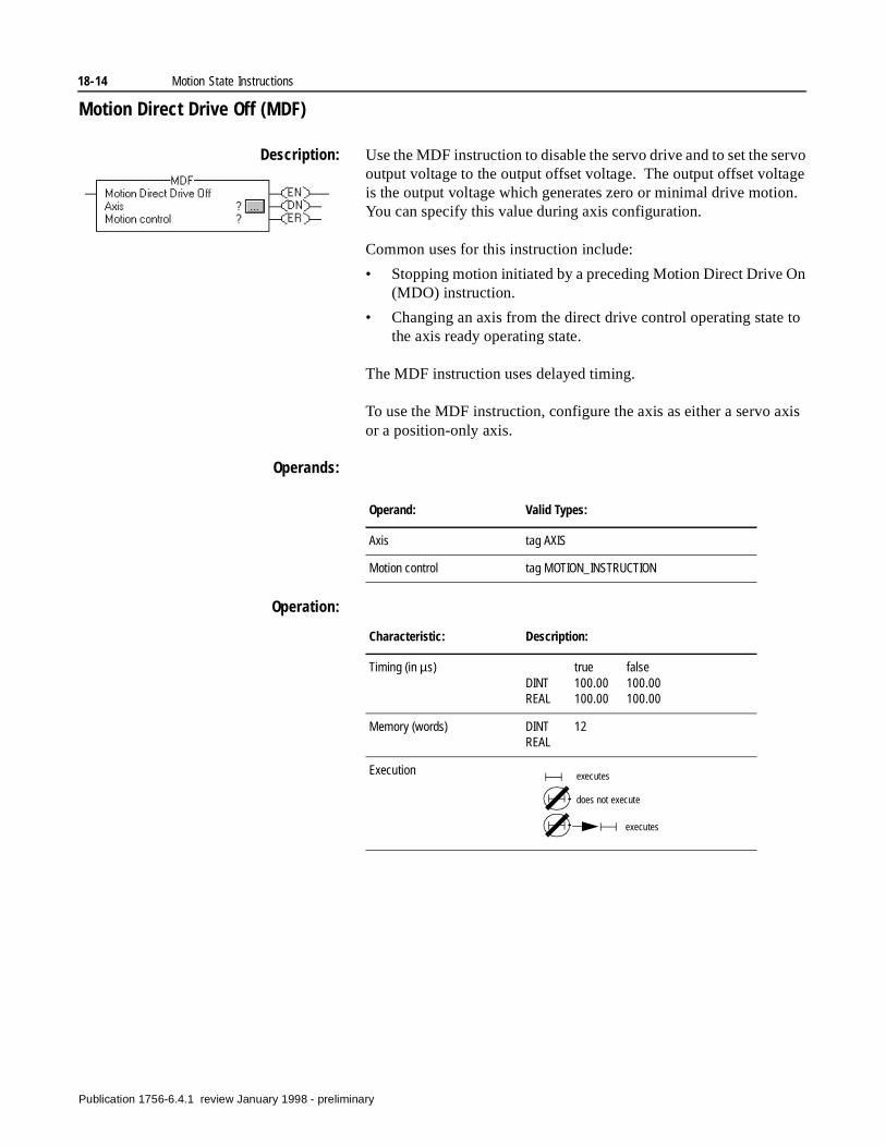
18-14 Motion State Instructions
n
xis
Motion Direct Drive Off (MDF)
Description: Use the MDF instruction to disable the servo drive and to set the servo output voltage to the output offset voltage. The output offset voltage is the output voltage which generates zero or minimal drive motion. You can specify this value during axis configuration.
Common uses for this instruction include:
• Stopping motion initiated by a preceding Motion Direct Drive O(MDO) instruction.
• Changing an axis from the direct drive control operating state to the axis ready operating state.
The MDF instruction uses delayed timing.
To use the MDF instruction, configure the axis as either a servo aor a position-only axis.
Operands:
Operation:
Operand: Valid Types:
Axis tag AXIS
Motion control tag MOTION_INSTRUCTION
Characteristic: Description:
Timing (in µs) true falseDINT 100.00 100.00REAL 100.00 100.00
Memory (words) DINT 12REAL
Execution executes
does not execute
executes
Publication 1756-6.4.1 review January 1998 - preliminary
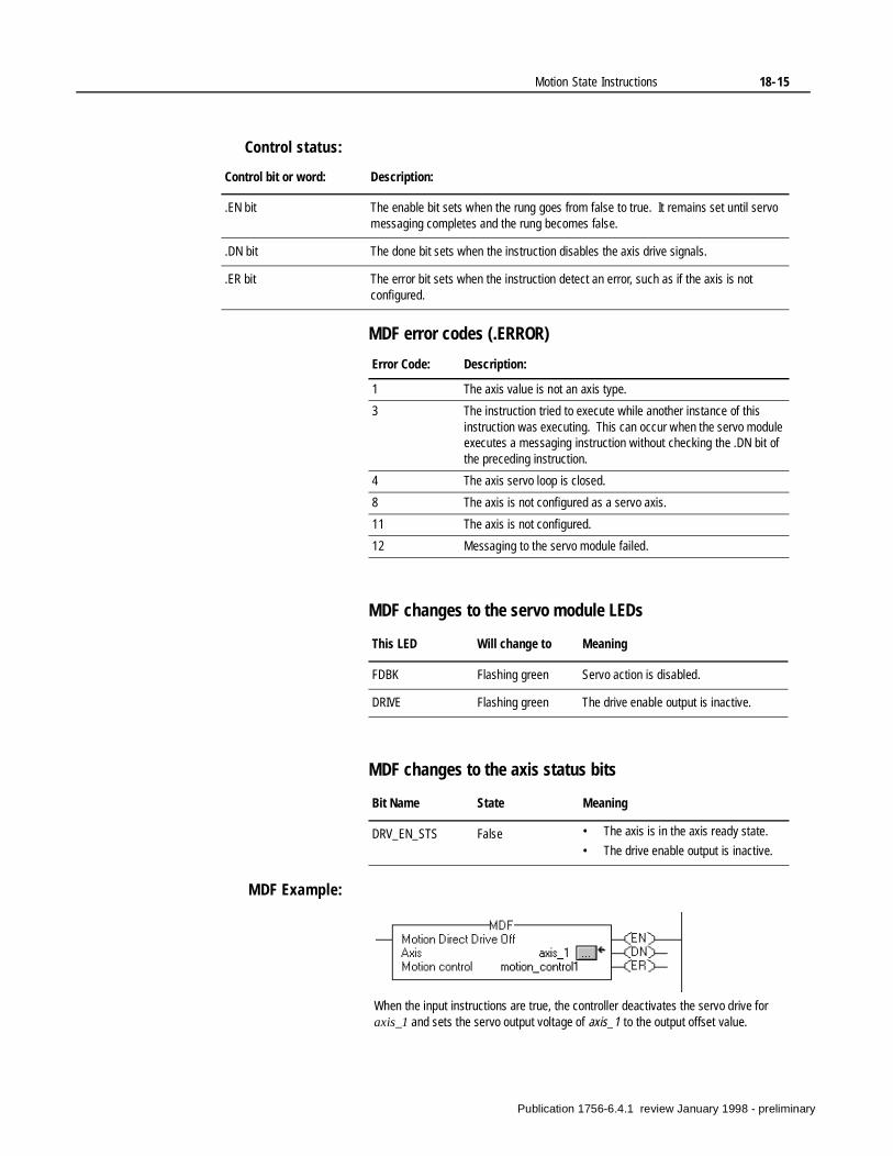
Motion State Instructions 18-15
Control status:
MDF error codes (.ERROR)
MDF changes to the servo module LEDs
MDF changes to the axis status bits
MDF Example:
Control bit or word: Description:
.EN bit The enable bit sets when the rung goes from false to true. It remains set until servo messaging completes and the rung becomes false.
.DN bit The done bit sets when the instruction disables the axis drive signals.
.ER bit The error bit sets when the instruction detect an error, such as if the axis is not configured.
Error Code: Description:
1 The axis value is not an axis type.
3 The instruction tried to execute while another instance of this instruction was executing. This can occur when the servo module executes a messaging instruction without checking the .DN bit of the preceding instruction.
4 The axis servo loop is closed.
8 The axis is not configured as a servo axis.
11 The axis is not configured.
12 Messaging to the servo module failed.
This LED Will change to Meaning
FDBK Flashing green Servo action is disabled.
DRIVE Flashing green The drive enable output is inactive.
Bit Name State Meaning
DRV_EN_STS False • The axis is in the axis ready state.
• The drive enable output is inactive.
When the input instructions are true, the controller deactivates the servo drive for axis_1 and sets the servo output voltage of axis_1 to the output offset value.
Publication 1756-6.4.1 review January 1998 - preliminary
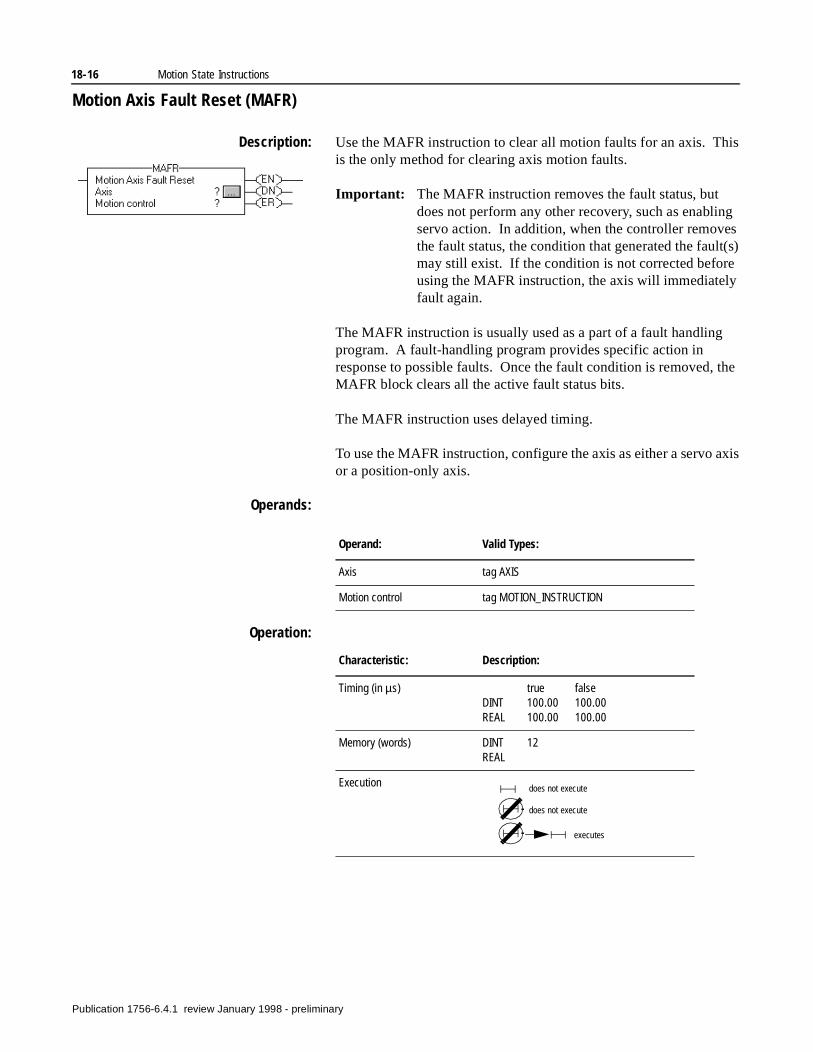
18-16 Motion State Instructions
Motion Axis Fault Reset (MAFR)
Description: Use the MAFR instruction to clear all motion faults for an axis. This is the only method for clearing axis motion faults.
Important: The MAFR instruction removes the fault status, but does not perform any other recovery, such as enabling servo action. In addition, when the controller removes the fault status, the condition that generated the fault(s) may still exist. If the condition is not corrected before using the MAFR instruction, the axis will immediately fault again.
The MAFR instruction is usually used as a part of a fault handling program. A fault-handling program provides specific action in response to possible faults. Once the fault condition is removed, the MAFR block clears all the active fault status bits.
The MAFR instruction uses delayed timing.
To use the MAFR instruction, configure the axis as either a servo axis or a position-only axis.
Operands:
Operation:
Operand: Valid Types:
Axis tag AXIS
Motion control tag MOTION_INSTRUCTION
Characteristic: Description:
Timing (in µs) true falseDINT 100.00 100.00REAL 100.00 100.00
Memory (words) DINT 12REAL
Execution does not execute
does not execute
executes
Publication 1756-6.4.1 review January 1998 - preliminary
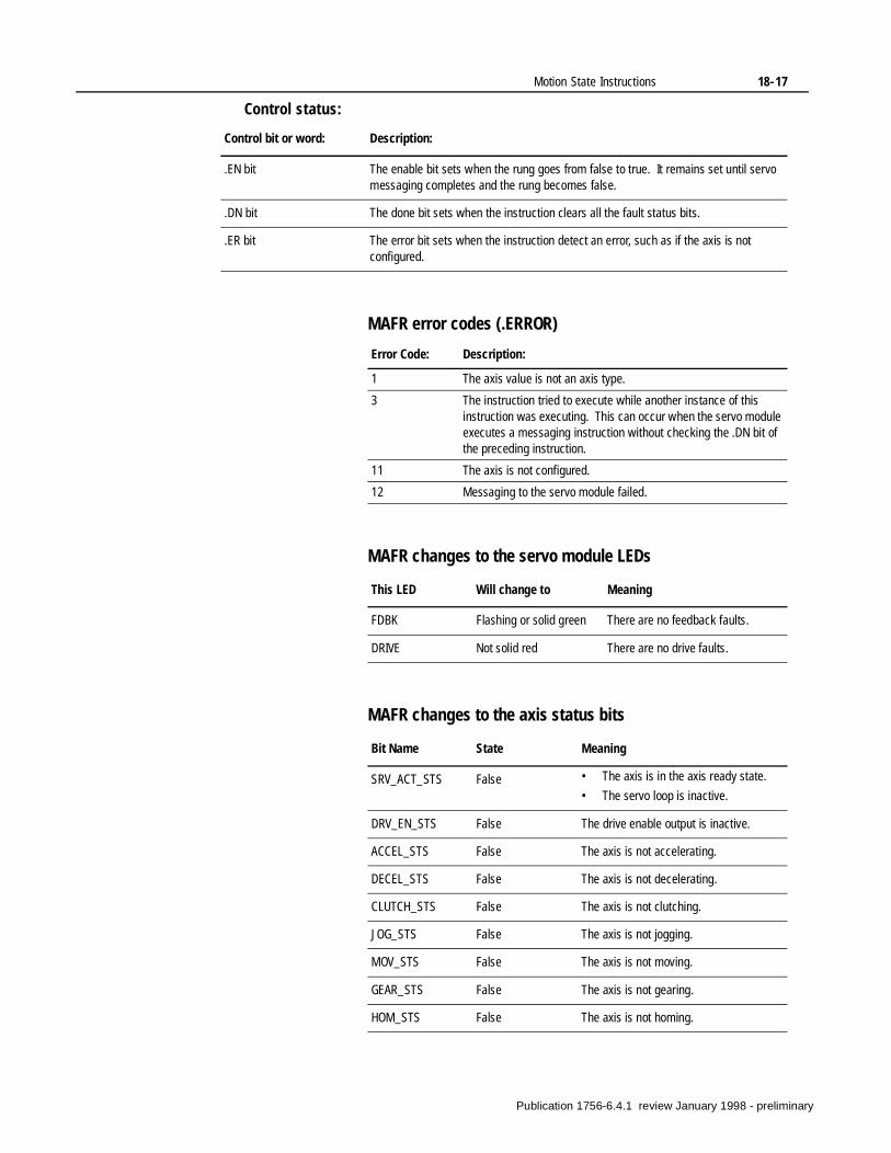
Motion State Instructions 18-17
Control status:
MAFR error codes (.ERROR)
MAFR changes to the servo module LEDs
MAFR changes to the axis status bits
Control bit or word: Description:
.EN bit The enable bit sets when the rung goes from false to true. It remains set until servo messaging completes and the rung becomes false.
.DN bit The done bit sets when the instruction clears all the fault status bits.
.ER bit The error bit sets when the instruction detect an error, such as if the axis is not configured.
Error Code: Description:
1 The axis value is not an axis type.
3 The instruction tried to execute while another instance of this instruction was executing. This can occur when the servo module executes a messaging instruction without checking the .DN bit of the preceding instruction.
11 The axis is not configured.
12 Messaging to the servo module failed.
This LED Will change to Meaning
FDBK Flashing or solid green There are no feedback faults.
DRIVE Not solid red There are no drive faults.
Bit Name State Meaning
SRV_ACT_STS False • The axis is in the axis ready state.
• The servo loop is inactive.
DRV_EN_STS False The drive enable output is inactive.
ACCEL_STS False The axis is not accelerating.
DECEL_STS False The axis is not decelerating.
CLUTCH_STS False The axis is not clutching.
JOG_STS False The axis is not jogging.
MOV_STS False The axis is not moving.
GEAR_STS False The axis is not gearing.
HOM_STS False The axis is not homing.
Publication 1756-6.4.1 review January 1998 - preliminary

18-18 Motion State Instructions
MAFR Example:
When the input instructions are true, the controller clears all motion faults for axis_1.
Publication 1756-6.4.1 review January 1998 - preliminary
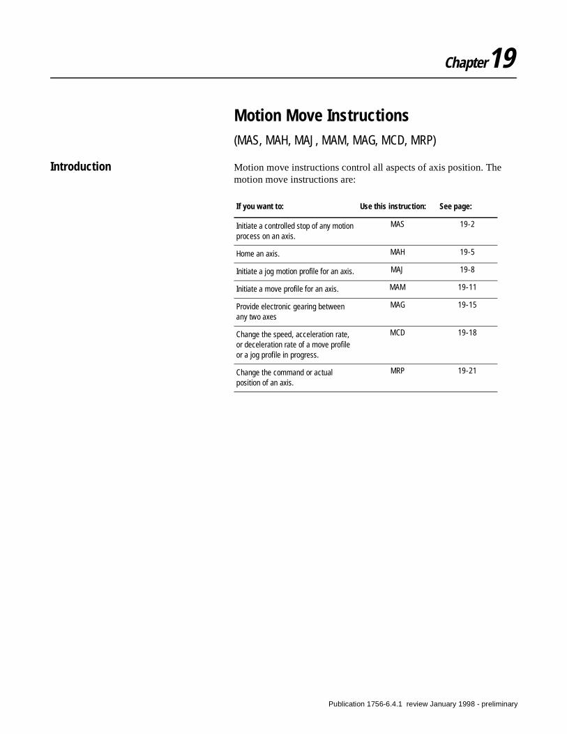
Chapter19
Motion Move Instructions(MAS, MAH, MAJ, MAM, MAG, MCD, MRP)
Introduction Motion move instructions control all aspects of axis position. The motion move instructions are:
If you want to: Use this instruction: See page:
Initiate a controlled stop of any motion process on an axis.
MAS 19-2
Home an axis. MAH 19-5
Initiate a jog motion profile for an axis. MAJ 19-8
Initiate a move profile for an axis. MAM 19-11
Provide electronic gearing between any two axes
MAG 19-15
Change the speed, acceleration rate, or deceleration rate of a move profile or a jog profile in progress.
MCD 19-18
Change the command or actual position of an axis.
MRP 19-21
Publication 1756-6.4.1 review January 1998 - preliminary
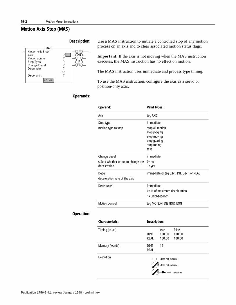
19-2 Motion Move Instructions
Motion Axis Stop (MAS)
Description: Use a MAS instruction to initiate a controlled stop of any motion process on an axis and to clear associated motion status flags.
Important: If the axis is not moving when the MAS instruction executes, the MAS instruction has no effect on motion.
The MAS instruction uses immediate and process type timing.
To use the MAS instruction, configure the axis as a servo or position-only axis.
Operands:
Operation:
Operand: Valid Types:
Axis tag AXIS
Stop type
motion type to stop
immediate
stop all motionstop joggingstop movingstop gearingstop tuningtest
Change decel
select whether or not to change the deceleration
immediate
0=no 1=yes
Decel
deceleration rate of the axis
immediate or tag SINT, INT, DINT, or REAL
Decel units immediate
0=% of maximum deceleration
1=units/second2
Motion control tag MOTION_INSTRUCTION
Characteristic: Description:
Timing (in µs) true falseDINT 100.00 100.00REAL 100.00 100.00
Memory (words) DINT 12REAL
Execution does not execute
does not execute
executes
Publication 1756-6.4.1 review January 1998 - preliminary
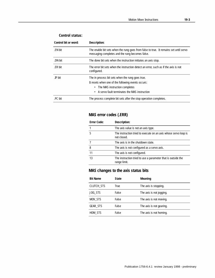
Motion Move Instructions 19-3
Control status:
MAS error codes (.ERR)
MAS changes to the axis status bits
Control bit or word: Description:
.EN bit The enable bit sets when the rung goes from false to true. It remains set until servo messaging completes and the rung becomes false.
.DN bit The done bit sets when the instruction initiates an axis stop.
.ER bit The error bit sets when the instruction detect an error, such as if the axis is not configured.
.IP bit The in process bit sets when the rung goes true.
It resets when one of the following events occurs:
• The MAS instruction completes
• A servo fault terminates the MAS instruction
.PC bit The process complete bit sets after the stop operation completes.
Error Code: Description:
1 The axis value is not an axis type.
5 The instruction tried to execute on an axis whose servo loop is not closed.
7 The axis is in the shutdown state.
8 The axis is not configured as a servo axis.
11 The axis is not configured.
13 The instruction tried to use a parameter that is outside the range limit.
Bit Name State Meaning
CLUTCH_STS True The axis is stopping.
JOG_STS False The axis is not jogging.
MOV_STS False The axis is not moving.
GEAR_STS False The axis is not gearing.
HOM_STS False The axis is not homing.
Publication 1756-6.4.1 review January 1998 - preliminary
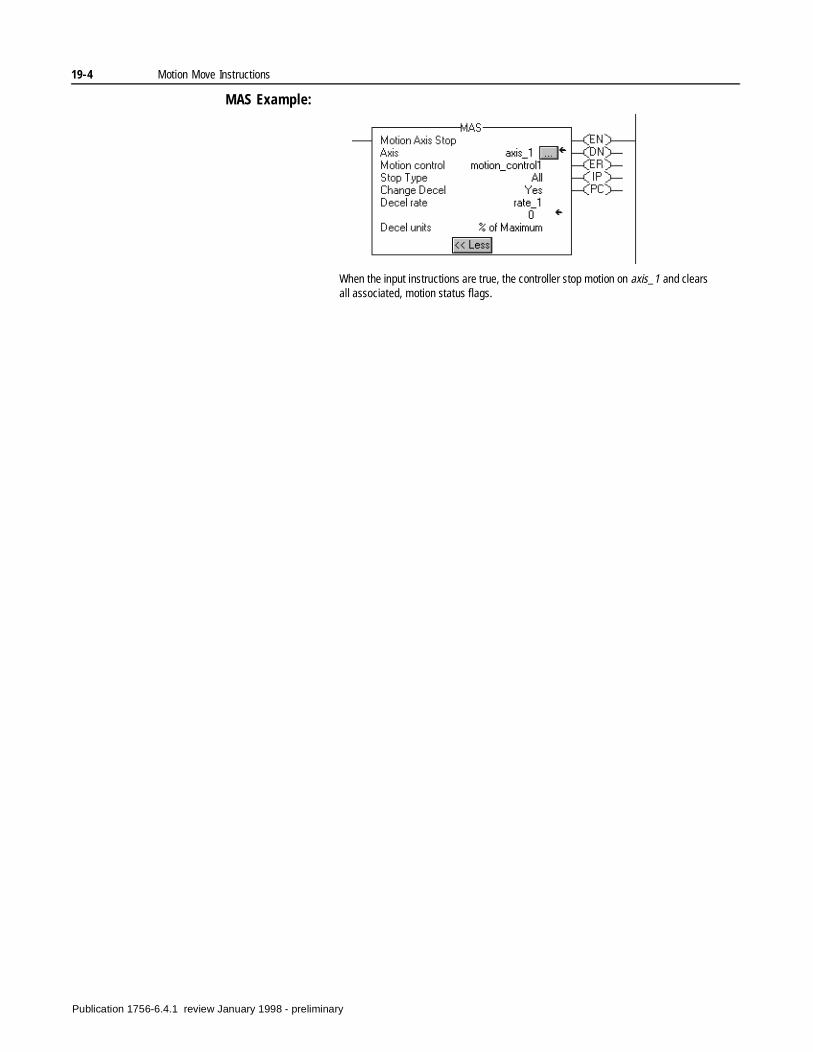
19-4 Motion Move Instructions
MAS Example:
When the input instructions are true, the controller stop motion on axis_1 and clears all associated, motion status flags.
Publication 1756-6.4.1 review January 1998 - preliminary
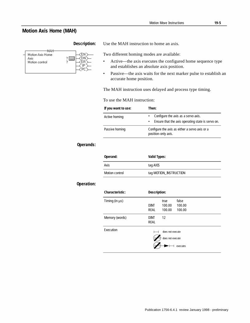
Motion Move Instructions 19-5
an
Motion Axis Home (MAH)
Description: Use the MAH instruction to home an axis.
Two different homing modes are available:
• Active—the axis executes the configured home sequence typeand establishes an absolute axis position.
• Passive—the axis waits for the next marker pulse to establishaccurate home position.
The MAH instruction uses delayed and process type timing.
To use the MAH instruction:
Operands:
Operation:
If you want to use: Then:
Active homing • Configure the axis as a servo axis.
• Ensure that the axis operating state is servo on.
Passive homing Configure the axis as either a servo axis or a position-only axis.
Operand: Valid Types:
Axis tag AXIS
Motion control tag MOTION_INSTRUCTION
Characteristic: Description:
Timing (in µs) true falseDINT 100.00 100.00REAL 100.00 100.00
Memory (words) DINT 12REAL
Execution does not execute
does not execute
executes
Publication 1756-6.4.1 review January 1998 - preliminary
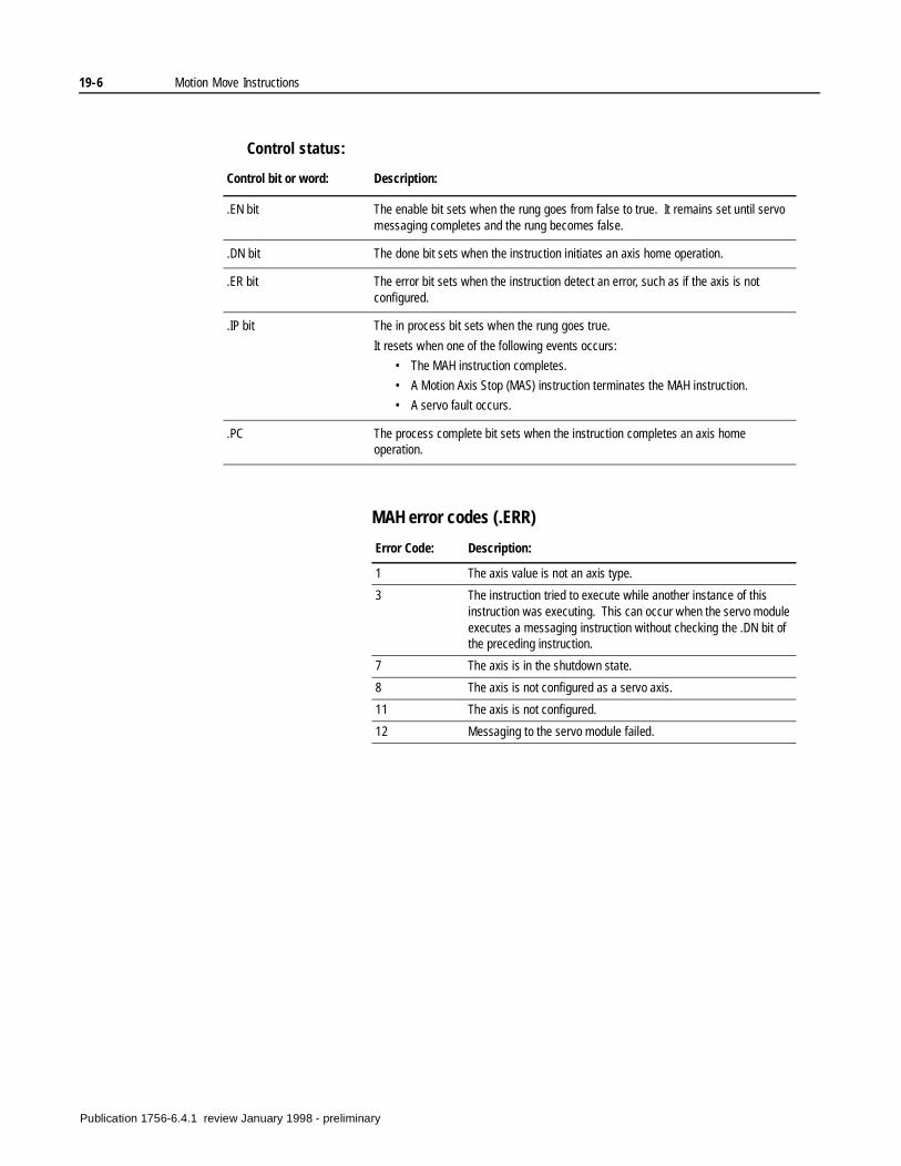
19-6 Motion Move Instructions
Control status:
MAH error codes (.ERR)
Control bit or word: Description:
.EN bit The enable bit sets when the rung goes from false to true. It remains set until servo messaging completes and the rung becomes false.
.DN bit The done bit sets when the instruction initiates an axis home operation.
.ER bit The error bit sets when the instruction detect an error, such as if the axis is not configured.
.IP bit The in process bit sets when the rung goes true.
It resets when one of the following events occurs:
• The MAH instruction completes.
• A Motion Axis Stop (MAS) instruction terminates the MAH instruction.
• A servo fault occurs.
.PC The process complete bit sets when the instruction completes an axis home operation.
Error Code: Description:
1 The axis value is not an axis type.
3 The instruction tried to execute while another instance of this instruction was executing. This can occur when the servo module executes a messaging instruction without checking the .DN bit of the preceding instruction.
7 The axis is in the shutdown state.
8 The axis is not configured as a servo axis.
11 The axis is not configured.
12 Messaging to the servo module failed.
Publication 1756-6.4.1 review January 1998 - preliminary
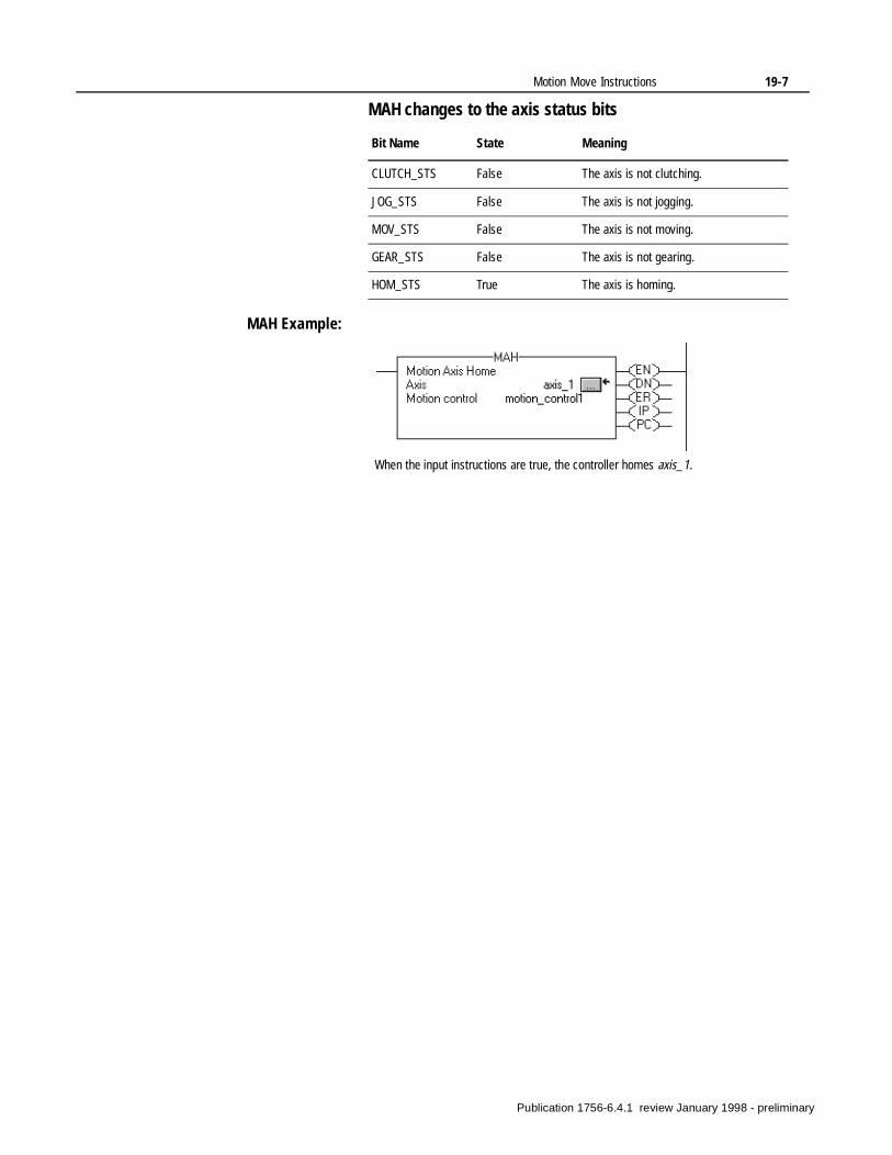
Motion Move Instructions 19-7
MAH changes to the axis status bits
MAH Example:
Bit Name State Meaning
CLUTCH_STS False The axis is not clutching.
JOG_STS False The axis is not jogging.
MOV_STS False The axis is not moving.
GEAR_STS False The axis is not gearing.
HOM_STS True The axis is homing.
When the input instructions are true, the controller homes axis_1.
Publication 1756-6.4.1 review January 1998 - preliminary
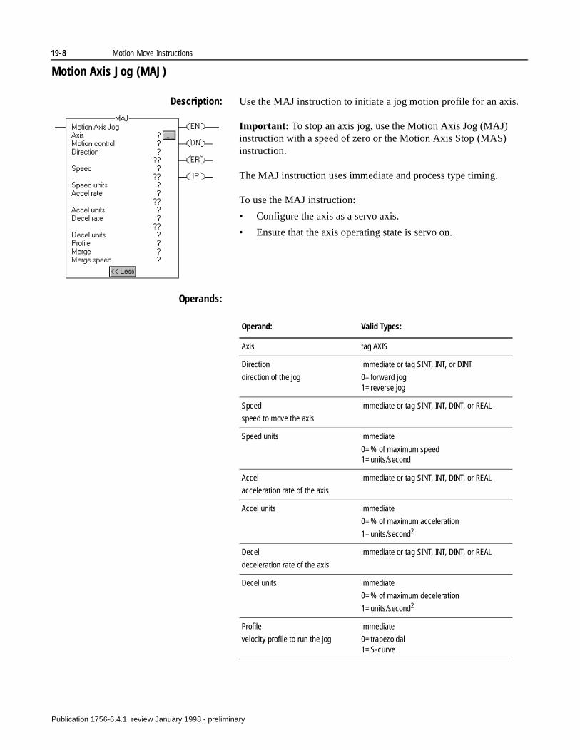
19-8 Motion Move Instructions
Motion Axis Jog (MAJ)
Description: Use the MAJ instruction to initiate a jog motion profile for an axis.
Important: To stop an axis jog, use the Motion Axis Jog (MAJ) instruction with a speed of zero or the Motion Axis Stop (MAS) instruction.
The MAJ instruction uses immediate and process type timing.
To use the MAJ instruction:
• Configure the axis as a servo axis.
• Ensure that the axis operating state is servo on.
Operands:
Operand: Valid Types:
Axis tag AXIS
Direction
direction of the jog
immediate or tag SINT, INT, or DINT
0=forward jog 1=reverse jog
Speed
speed to move the axis
immediate or tag SINT, INT, DINT, or REAL
Speed units immediate
0=% of maximum speed1=units/second
Accel
acceleration rate of the axis
immediate or tag SINT, INT, DINT, or REAL
Accel units immediate
0=% of maximum acceleration
1=units/second2
Decel
deceleration rate of the axis
immediate or tag SINT, INT, DINT, or REAL
Decel units immediate
0=% of maximum deceleration
1=units/second2
Profile
velocity profile to run the jog
immediate
0=trapezoidal 1=S-curve
Publication 1756-6.4.1 review January 1998 - preliminary
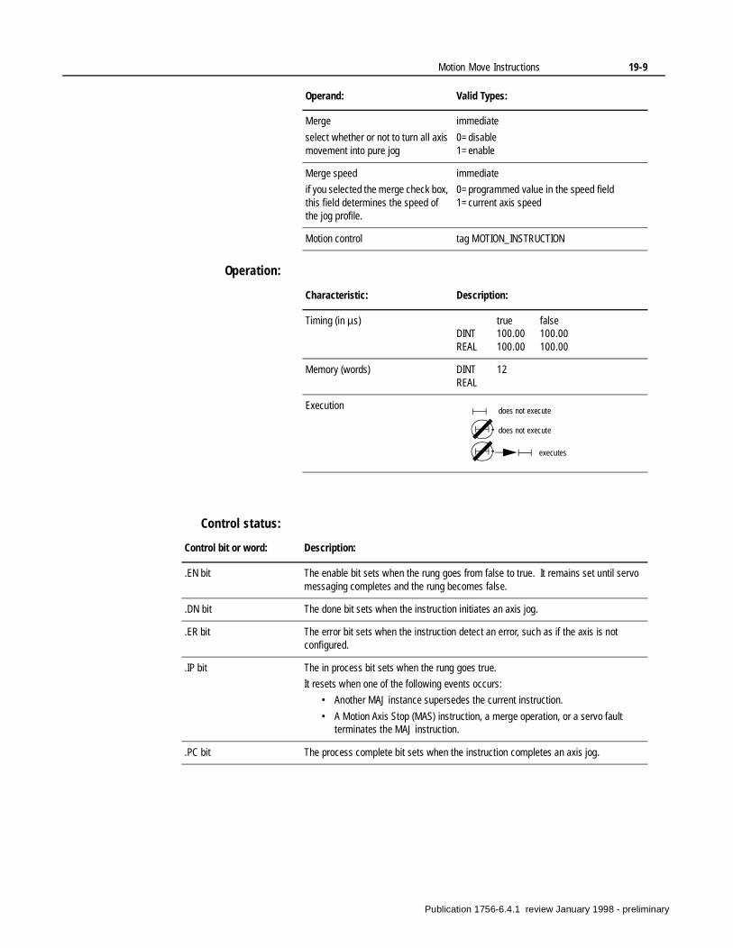
Motion Move Instructions 19-9
Operation:
Control status:
Merge
select whether or not to turn all axis movement into pure jog
immediate
0=disable 1=enable
Merge speed
if you selected the merge check box, this field determines the speed of the jog profile.
immediate
0=programmed value in the speed field 1=current axis speed
Motion control tag MOTION_INSTRUCTION
Operand: Valid Types:
Characteristic: Description:
Timing (in µs) true falseDINT 100.00 100.00REAL 100.00 100.00
Memory (words) DINT 12REAL
Execution does not execute
does not execute
executes
Control bit or word: Description:
.EN bit The enable bit sets when the rung goes from false to true. It remains set until servo messaging completes and the rung becomes false.
.DN bit The done bit sets when the instruction initiates an axis jog.
.ER bit The error bit sets when the instruction detect an error, such as if the axis is not configured.
.IP bit The in process bit sets when the rung goes true.
It resets when one of the following events occurs:
• Another MAJ instance supersedes the current instruction.
• A Motion Axis Stop (MAS) instruction, a merge operation, or a servo fault terminates the MAJ instruction.
.PC bit The process complete bit sets when the instruction completes an axis jog.
Publication 1756-6.4.1 review January 1998 - preliminary
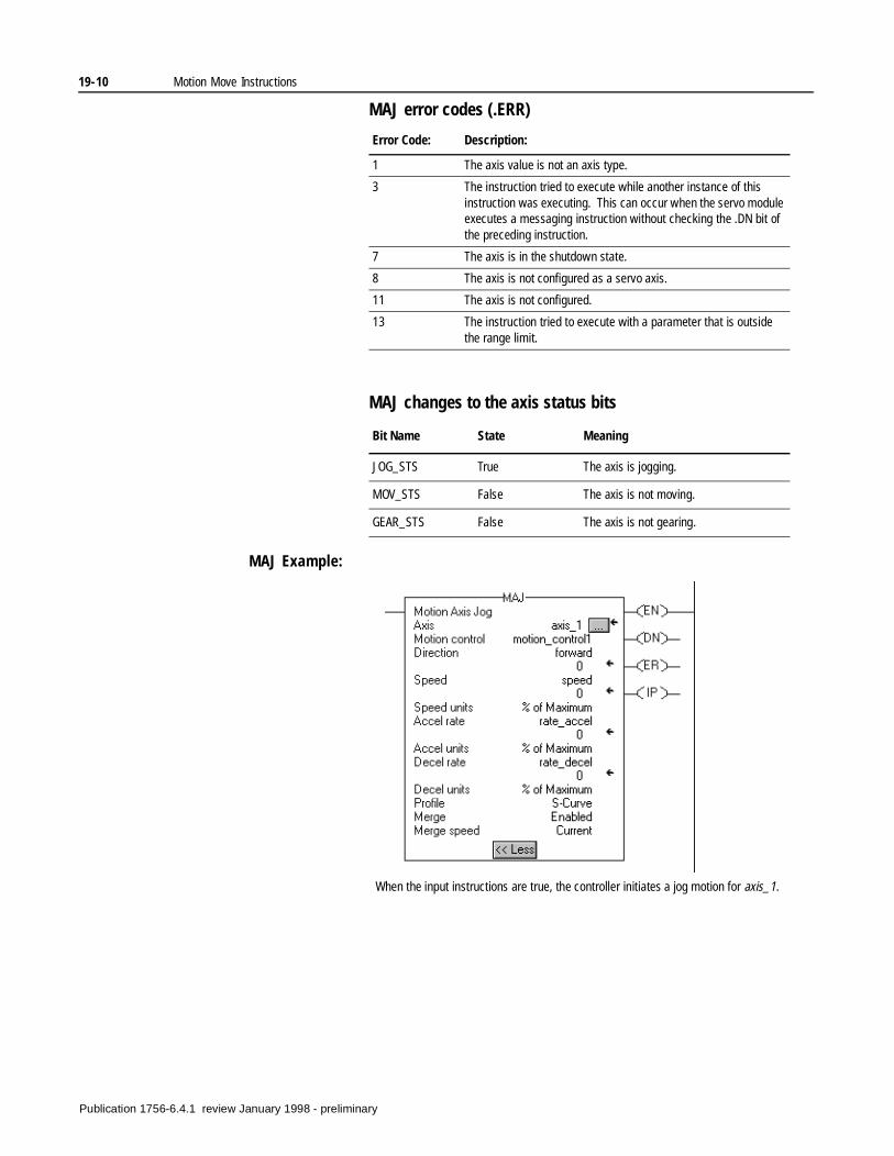
19-10 Motion Move Instructions
MAJ error codes (.ERR)
MAJ changes to the axis status bits
MAJ Example:
Error Code: Description:
1 The axis value is not an axis type.
3 The instruction tried to execute while another instance of this instruction was executing. This can occur when the servo module executes a messaging instruction without checking the .DN bit of the preceding instruction.
7 The axis is in the shutdown state.
8 The axis is not configured as a servo axis.
11 The axis is not configured.
13 The instruction tried to execute with a parameter that is outside the range limit.
Bit Name State Meaning
JOG_STS True The axis is jogging.
MOV_STS False The axis is not moving.
GEAR_STS False The axis is not gearing.
When the input instructions are true, the controller initiates a jog motion for axis_1.
Publication 1756-6.4.1 review January 1998 - preliminary
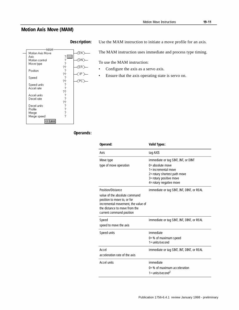
Motion Move Instructions 19-11
Motion Axis Move (MAM)
Description: Use the MAM instruction to initiate a move profile for an axis.
The MAM instruction uses immediate and process type timing.
To use the MAM instruction:
• Configure the axis as a servo axis.
• Ensure that the axis operating state is servo on.
Operands:
Operand: Valid Types:
Axis tag AXIS
Move type
type of move operation
immediate or tag SINT, INT, or DINT
0=absolute move1=incremental move2=rotary shortest path move3=rotary positive move4=rotary negative move
Position/Distance
value of the absolute command position to move to, or for incremental movement, the value of the distance to move from the current command position
immediate or tag SINT, INT, DINT, or REAL
Speed
speed to move the axis
immediate or tag SINT, INT, DINT, or REAL
Speed units immediate
0=% of maximum speed1=units/second
Accel
acceleration rate of the axis
immediate or tag SINT, INT, DINT, or REAL
Accel units immediate
0=% of maximum acceleration
1=units/second2
Publication 1756-6.4.1 review January 1998 - preliminary
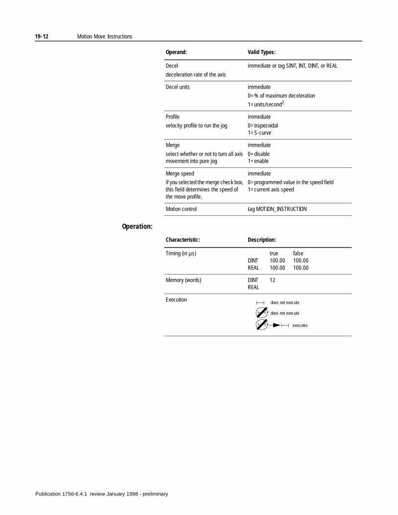
19-12 Motion Move Instructions
Operation:
Decel
deceleration rate of the axis
immediate or tag SINT, INT, DINT, or REAL
Decel units immediate
0=% of maximum deceleration
1=units/second2
Profile
velocity profile to run the jog
immediate
0=trapezoidal 1=S-curve
Merge
select whether or not to turn all axis movement into pure jog
immediate
0=disable 1=enable
Merge speed
if you selected the merge check box, this field determines the speed of the move profile.
immediate
0=programmed value in the speed field 1=current axis speed
Motion control tag MOTION_INSTRUCTION
Operand: Valid Types:
Characteristic: Description:
Timing (in µs) true falseDINT 100.00 100.00REAL 100.00 100.00
Memory (words) DINT 12REAL
Execution does not execute
does not execute
executes
Publication 1756-6.4.1 review January 1998 - preliminary
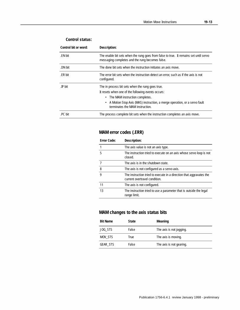
Motion Move Instructions 19-13
Control status:
MAM error codes (.ERR)
MAM changes to the axis status bits
Control bit or word: Description:
.EN bit The enable bit sets when the rung goes from false to true. It remains set until servo messaging completes and the rung becomes false.
.DN bit The done bit sets when the instruction initiates an axis move.
.ER bit The error bit sets when the instruction detect an error, such as if the axis is not configured.
.IP bit The in process bit sets when the rung goes true.
It resets when one of the following events occurs:
• The MAM instruction completes.
• A Motion Stop Axis (MAS) instruction, a merge operation, or a servo fault terminates the MAM instruction.
.PC bit The process complete bit sets when the instruction completes an axis move.
Error Code: Description:
1 The axis value is not an axis type.
5 The instruction tried to execute on an axis whose servo loop is not closed.
7 The axis is in the shutdown state.
8 The axis is not configured as a servo axis.
9 The instruction tried to execute in a direction that aggravates the current overtravel condition.
11 The axis is not configured.
13 The instruction tried to use a parameter that is outside the legal range limit.
Bit Name State Meaning
JOG_STS False The axis is not jogging.
MOV_STS True The axis is moving.
GEAR_STS False The axis is not gearing.
Publication 1756-6.4.1 review January 1998 - preliminary
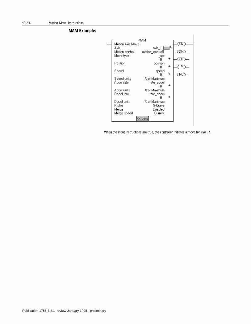
19-14 Motion Move Instructions
MAM Example:
When the input instructions are true, the controller initiates a move for axis_1.
Publication 1756-6.4.1 review January 1998 - preliminary
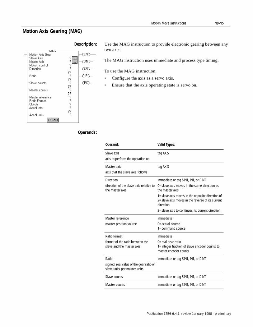
Motion Move Instructions 19-15
Motion Axis Gearing (MAG)
Description: Use the MAG instruction to provide electronic gearing between any two axes.
The MAG instruction uses immediate and process type timing.
To use the MAG instruction:
• Configure the axis as a servo axis.
• Ensure that the axis operating state is servo on.
Operands:
Operand: Valid Types:
Slave axis
axis to perform the operation on
tag AXIS
Master axis
axis that the slave axis follows
tag AXIS
Direction
direction of the slave axis relative to the master axis
immediate or tag SINT, INT, or DINT
0=slave axis moves in the same direction as the master axis
1=slave axis moves in the opposite direction of 2=slave axis moves in the reverse of its current direction
3=slave axis to continues its current direction
Master reference
master position source
immediate
0=actual source 1=command source
Ratio format
format of the ratio between the slave and the master axis
immediate
0=real gear ratio1=integer fraction of slave encoder counts to master encoder counts
Ratio
signed, real value of the gear ratio of slave units per master units
immediate or tag SINT, INT, or DINT
Slave counts immediate or tag SINT, INT, or DINT
Master counts immediate or tag SINT, INT, or DINT
Publication 1756-6.4.1 review January 1998 - preliminary
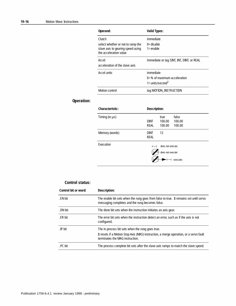
19-16 Motion Move Instructions
Operation:
Control status:
Clutch
select whether or not to ramp the slave axis to gearing speed using the acceleration value
immediate
0=disable1=enable
Accel
acceleration of the slave axis
immediate or tag SINT, INT, DINT, or REAL
Accel units immediate
0=% of maximum acceleration
1=units/second2
Motion control tag MOTION_INSTRUCTION
Operand: Valid Types:
Characteristic: Description:
Timing (in µs) true falseDINT 100.00 100.00REAL 100.00 100.00
Memory (words) DINT 12REAL
Execution does not execute
does not execute
executes
Control bit or word: Description:
.EN bit The enable bit sets when the rung goes from false to true. It remains set until servo messaging completes and the rung becomes false.
.DN bit The done bit sets when the instruction initiates an axis gear.
.ER bit The error bit sets when the instruction detect an error, such as if the axis is not configured.
.IP bit The in process bit sets when the rung goes true.
It resets if a Motion Stop Axis (MAS) instruction, a merge operation, or a servo fault terminates the MAG instruction.
.PC bit The process complete bit sets after the slave axis ramps to match the slave speed.
Publication 1756-6.4.1 review January 1998 - preliminary
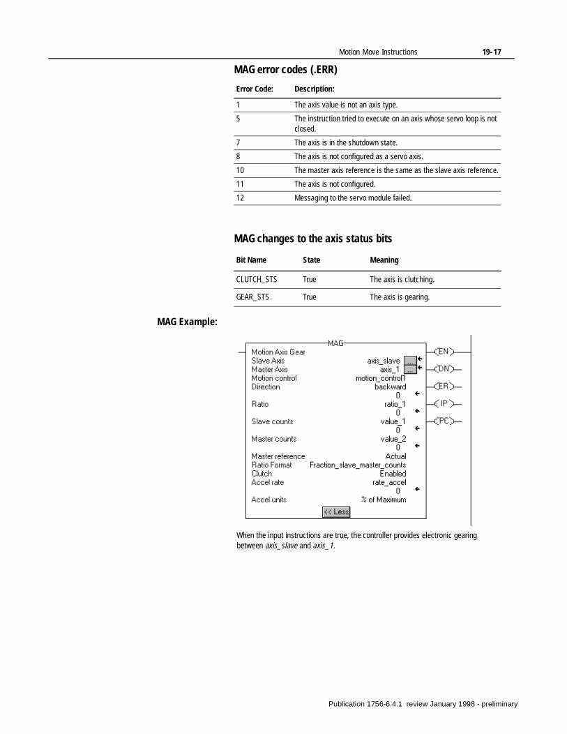
Motion Move Instructions 19-17
MAG error codes (.ERR)
MAG changes to the axis status bits
MAG Example:
Error Code: Description:
1 The axis value is not an axis type.
5 The instruction tried to execute on an axis whose servo loop is not closed.
7 The axis is in the shutdown state.
8 The axis is not configured as a servo axis.
10 The master axis reference is the same as the slave axis reference.
11 The axis is not configured.
12 Messaging to the servo module failed.
Bit Name State Meaning
CLUTCH_STS True The axis is clutching.
GEAR_STS True The axis is gearing.
When the input instructions are true, the controller provides electronic gearing between axis_slave and axis_1.
Publication 1756-6.4.1 review January 1998 - preliminary
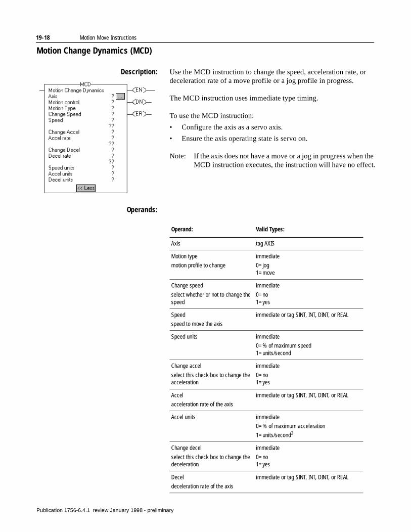
19-18 Motion Move Instructions
the
Motion Change Dynamics (MCD)
Description: Use the MCD instruction to change the speed, acceleration rate, or deceleration rate of a move profile or a jog profile in progress.
The MCD instruction uses immediate type timing.
To use the MCD instruction:
• Configure the axis as a servo axis.
• Ensure the axis operating state is servo on.
Note: If the axis does not have a move or a jog in progress whenMCD instruction executes, the instruction will have no effect.
Operands:
Operand: Valid Types:
Axis tag AXIS
Motion type
motion profile to change
immediate
0=jog 1=move
Change speed
select whether or not to change the speed
immediate
0=no1=yes
Speed
speed to move the axis
immediate or tag SINT, INT, DINT, or REAL
Speed units immediate
0=% of maximum speed 1=units/second
Change accel
select this check box to change the acceleration
immediate
0=no 1=yes
Accel
acceleration rate of the axis
immediate or tag SINT, INT, DINT, or REAL
Accel units immediate
0=% of maximum acceleration
1=units/second2
Change decel
select this check box to change the deceleration
immediate
0=no 1=yes
Decel
deceleration rate of the axis
immediate or tag SINT, INT, DINT, or REAL
Publication 1756-6.4.1 review January 1998 - preliminary
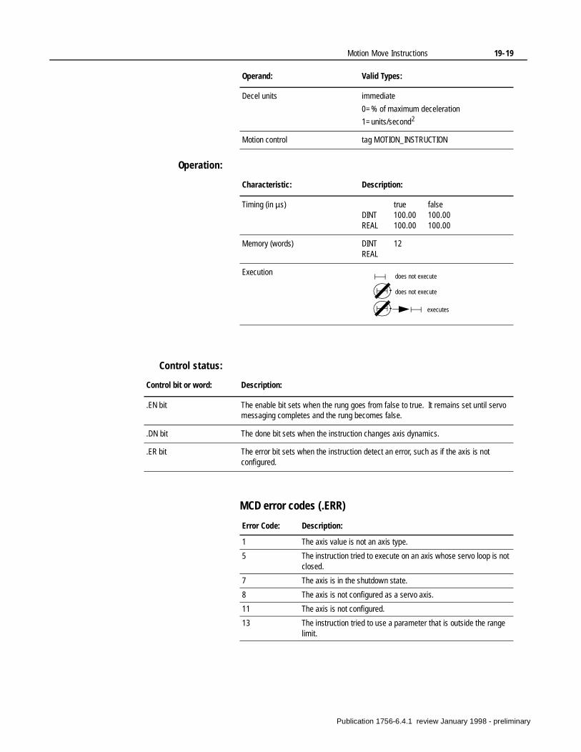
Motion Move Instructions 19-19
Operation:
Control status:
MCD error codes (.ERR)
Decel units immediate
0=% of maximum deceleration
1=units/second2
Motion control tag MOTION_INSTRUCTION
Operand: Valid Types:
Characteristic: Description:
Timing (in µs) true falseDINT 100.00 100.00REAL 100.00 100.00
Memory (words) DINT 12REAL
Execution does not execute
does not execute
executes
Control bit or word: Description:
.EN bit The enable bit sets when the rung goes from false to true. It remains set until servo messaging completes and the rung becomes false.
.DN bit The done bit sets when the instruction changes axis dynamics.
.ER bit The error bit sets when the instruction detect an error, such as if the axis is not configured.
Error Code: Description:
1 The axis value is not an axis type.
5 The instruction tried to execute on an axis whose servo loop is not closed.
7 The axis is in the shutdown state.
8 The axis is not configured as a servo axis.
11 The axis is not configured.
13 The instruction tried to use a parameter that is outside the range limit.
Publication 1756-6.4.1 review January 1998 - preliminary
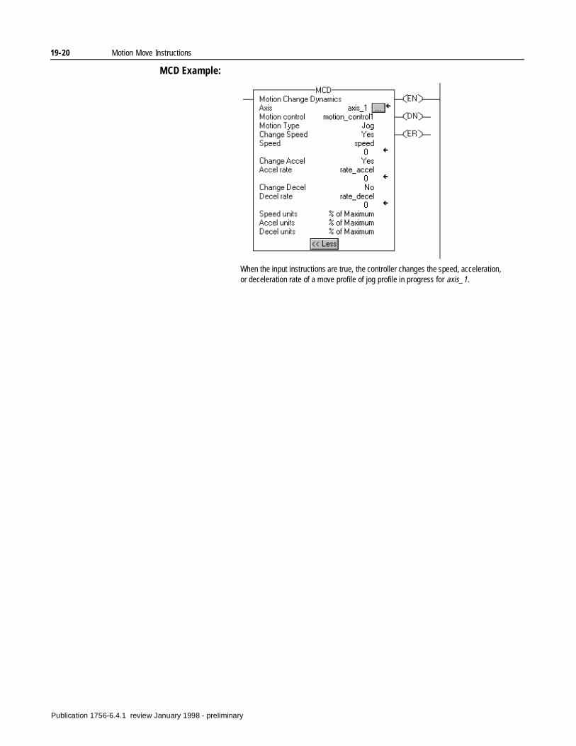
19-20 Motion Move Instructions
MCD Example:
When the input instructions are true, the controller changes the speed, acceleration, or deceleration rate of a move profile of jog profile in progress for axis_1.
Publication 1756-6.4.1 review January 1998 - preliminary
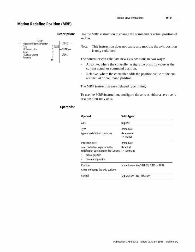
Motion Move Instructions 19-21
e
r-
xis
Motion Redefine Position (MRP)
Description: Use the MRP instruction to change the command or actual position of an axis.
Note: This instruction does not cause any motion; the axis position is only redefined.
The controller can calculate new axis positions in two ways:
• Absolute, where the controller assigns the position value as thcurrent actual or command position.
• Relative, where the controller adds the position value to the curent actual or command position.
The MRP instruction uses delayed type timing.
To use the MRP instruction, configure the axis as either a servo aor a position-only axis.
Operands:
Operand: Valid Types:
Axis tag AXIS
Type
type of redefinition operation
immediate
0=absolute1=relative
Position select
select whether to perform the redefinition operation on the current:
• actual position
• command position
immediate
0=actual 1=command
Position
value to change the axis position
immediate or tag SINT, IN, DINT, or REAL
Control tag MOTION_INSTRUCTION
Publication 1756-6.4.1 review January 1998 - preliminary
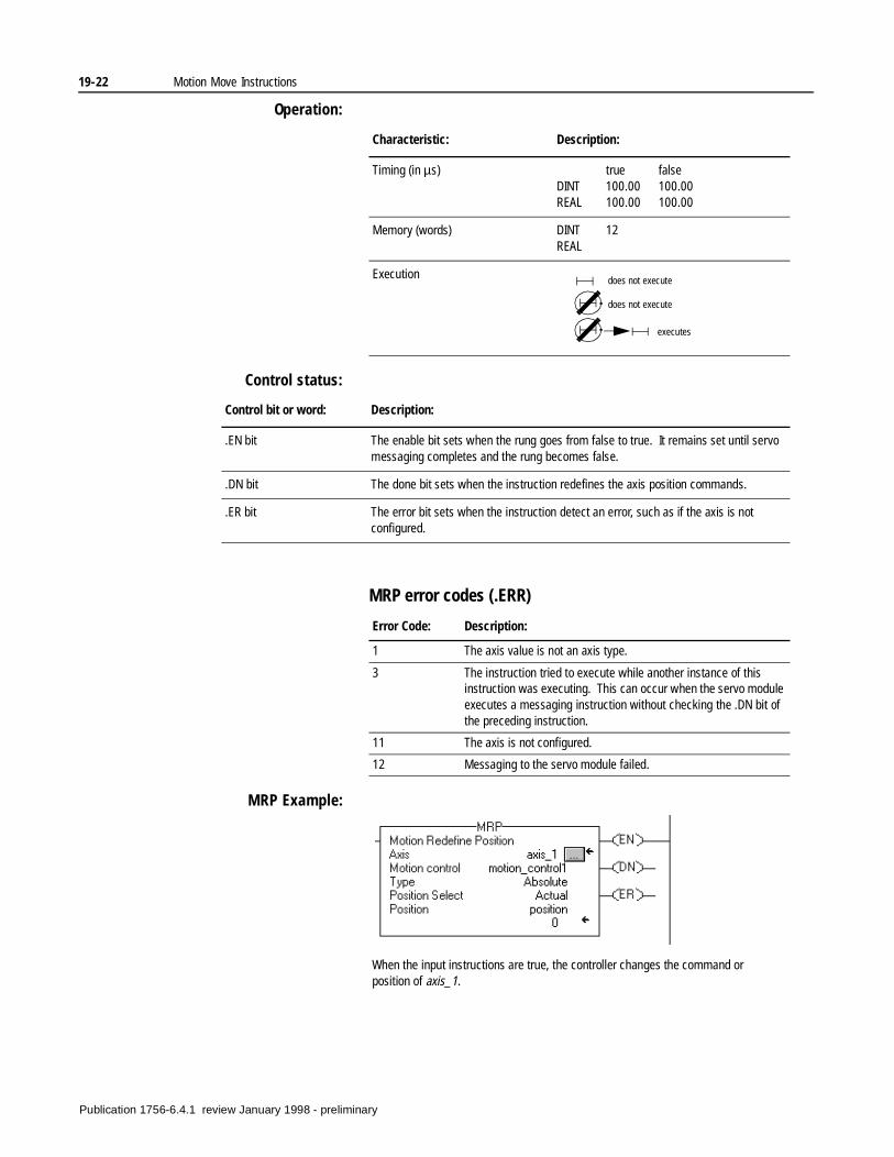
19-22 Motion Move Instructions
Operation:
Control status:
MRP error codes (.ERR)
MRP Example:
Characteristic: Description:
Timing (in µs) true falseDINT 100.00 100.00REAL 100.00 100.00
Memory (words) DINT 12REAL
Execution does not execute
does not execute
executes
Control bit or word: Description:
.EN bit The enable bit sets when the rung goes from false to true. It remains set until servo messaging completes and the rung becomes false.
.DN bit The done bit sets when the instruction redefines the axis position commands.
.ER bit The error bit sets when the instruction detect an error, such as if the axis is not configured.
Error Code: Description:
1 The axis value is not an axis type.
3 The instruction tried to execute while another instance of this instruction was executing. This can occur when the servo module executes a messaging instruction without checking the .DN bit of the preceding instruction.
11 The axis is not configured.
12 Messaging to the servo module failed.
When the input instructions are true, the controller changes the command or position of axis_1.
Publication 1756-6.4.1 review January 1998 - preliminary
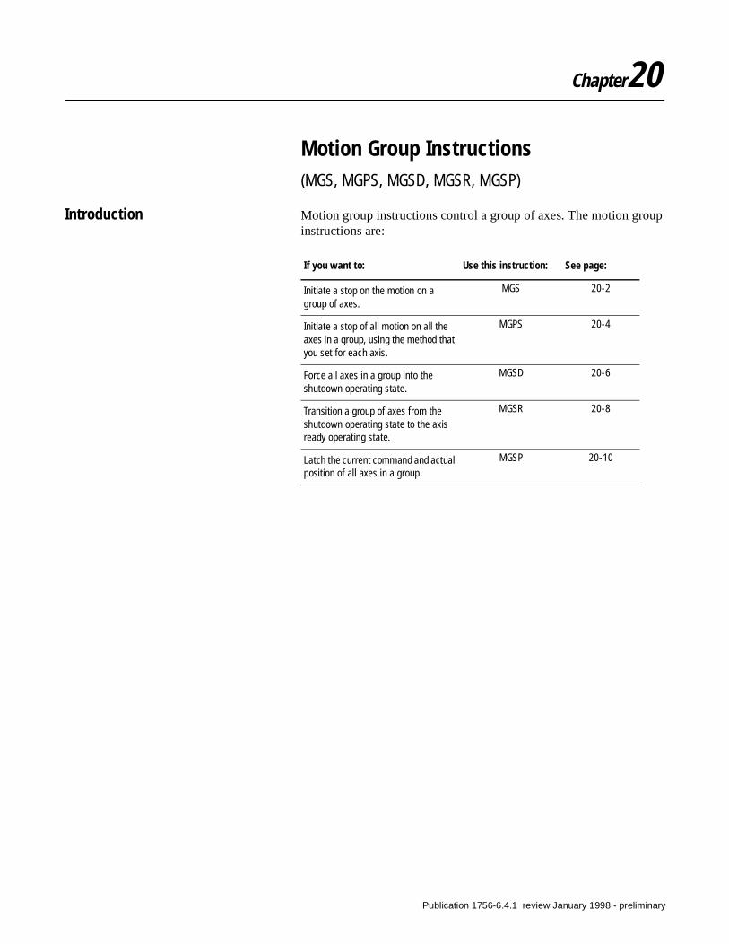
Chapter20
Motion Group Instructions(MGS, MGPS, MGSD, MGSR, MGSP)
Introduction Motion group instructions control a group of axes. The motion group instructions are:
If you want to: Use this instruction: See page:
Initiate a stop on the motion on a group of axes.
MGS 20-2
Initiate a stop of all motion on all the axes in a group, using the method that you set for each axis.
MGPS 20-4
Force all axes in a group into the shutdown operating state.
MGSD 20-6
Transition a group of axes from the shutdown operating state to the axis ready operating state.
MGSR 20-8
Latch the current command and actual position of all axes in a group.
MGSP 20-10
Publication 1756-6.4.1 review January 1998 - preliminary
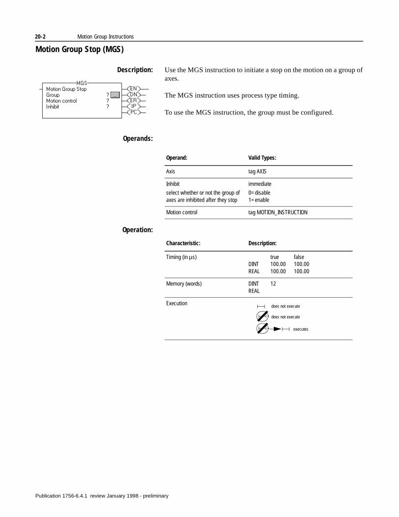
20-2 Motion Group Instructions
Motion Group Stop (MGS)
Description: Use the MGS instruction to initiate a stop on the motion on a group of axes.
The MGS instruction uses process type timing.
To use the MGS instruction, the group must be configured.
Operands:
Operation:
Operand: Valid Types:
Axis tag AXIS
Inhibit
select whether or not the group of axes are inhibited after they stop
immediate
0=disable1=enable
Motion control tag MOTION_INSTRUCTION
Characteristic: Description:
Timing (in µs) true falseDINT 100.00 100.00REAL 100.00 100.00
Memory (words) DINT 12REAL
Execution does not execute
does not execute
executes
Publication 1756-6.4.1 review January 1998 - preliminary
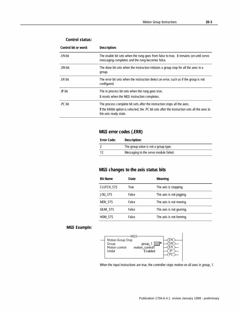
Motion Group Instructions 20-3
Control status:
MGS error codes (.ERR)
MGS changes to the axis status bits
MGS Example:
Control bit or word: Description:
.EN bit The enable bit sets when the rung goes from false to true. It remains set until servo messaging completes and the rung becomes false.
.DN bit The done bit sets when the instruction initiates a group stop for all the axes in a group.
.ER bit The error bit sets when the instruction detect an error, such as if the group is not configured.
.IP bit The in process bit sets when the rung goes true.
It resets when the MGS instruction completes.
.PC bit The process complete bit sets after the instruction stops all the axes.
If the Inhibit option is selected, the .PC bit sets after the instruction sets all the axes to the axis ready state.
Error Code: Description:
2 The group value is not a group type.
12 Messaging to the servo module failed.
Bit Name State Meaning
CLUTCH_STS True The axis is stopping.
JOG_STS False The axis is not jogging.
MOV_STS False The axis is not moving.
GEAR_STS False The axis is not gearing.
HOM_STS False The axis is not homing.
When the input instructions are true, the controller stops motion on all axes in group_1.
Publication 1756-6.4.1 review January 1998 - preliminary
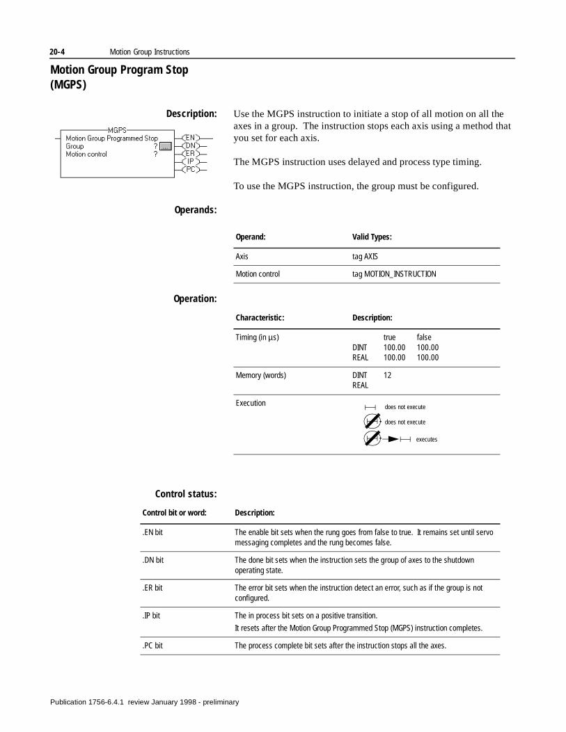
20-4 Motion Group Instructions
Motion Group Program Stop (MGPS)
Description: Use the MGPS instruction to initiate a stop of all motion on all the axes in a group. The instruction stops each axis using a method that you set for each axis.
The MGPS instruction uses delayed and process type timing.
To use the MGPS instruction, the group must be configured.
Operands:
Operation:
Control status:
Operand: Valid Types:
Axis tag AXIS
Motion control tag MOTION_INSTRUCTION
Characteristic: Description:
Timing (in µs) true falseDINT 100.00 100.00REAL 100.00 100.00
Memory (words) DINT 12REAL
Execution does not execute
does not execute
executes
Control bit or word: Description:
.EN bit The enable bit sets when the rung goes from false to true. It remains set until servo messaging completes and the rung becomes false.
.DN bit The done bit sets when the instruction sets the group of axes to the shutdown operating state.
.ER bit The error bit sets when the instruction detect an error, such as if the group is not configured.
.IP bit The in process bit sets on a positive transition.
It resets after the Motion Group Programmed Stop (MGPS) instruction completes.
.PC bit The process complete bit sets after the instruction stops all the axes.
Publication 1756-6.4.1 review January 1998 - preliminary
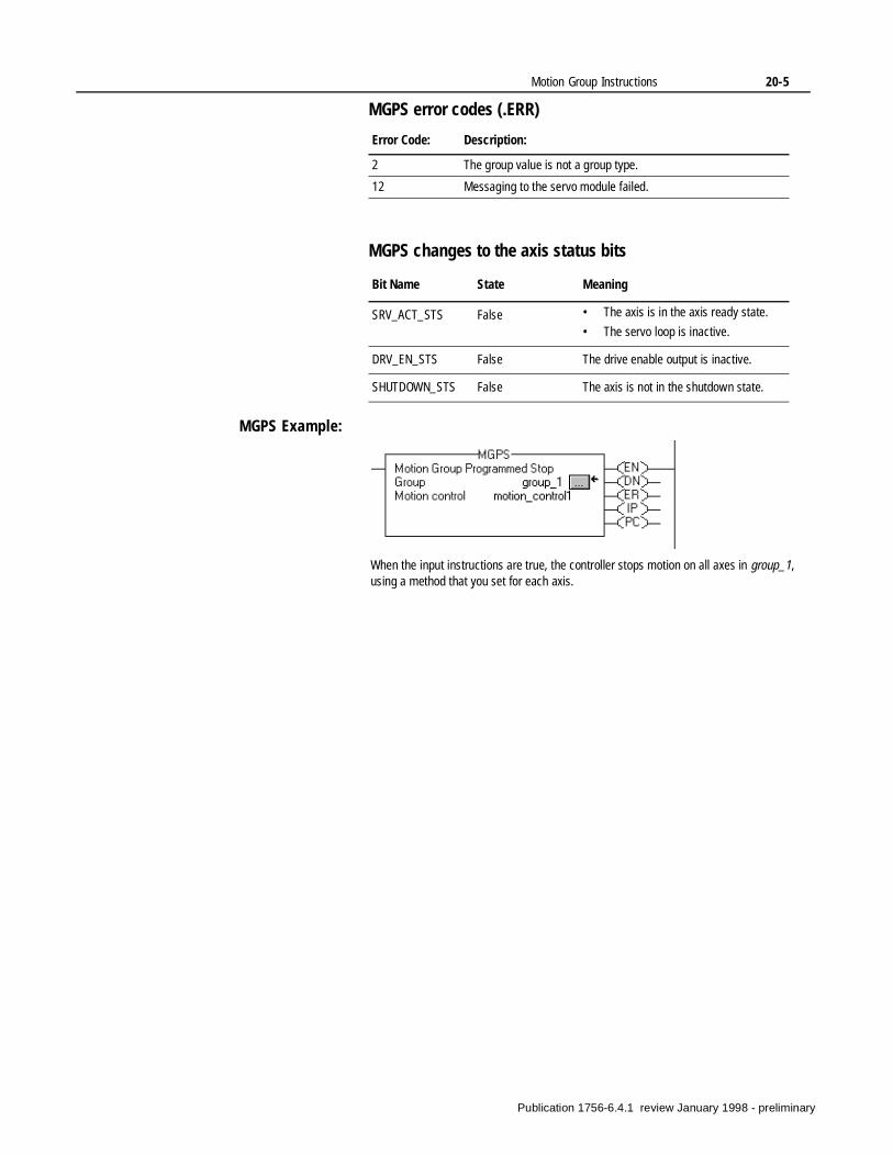
Motion Group Instructions 20-5
MGPS error codes (.ERR)
MGPS changes to the axis status bits
MGPS Example:
Error Code: Description:
2 The group value is not a group type.
12 Messaging to the servo module failed.
Bit Name State Meaning
SRV_ACT_STS False • The axis is in the axis ready state.
• The servo loop is inactive.
DRV_EN_STS False The drive enable output is inactive.
SHUTDOWN_STS False The axis is not in the shutdown state.
When the input instructions are true, the controller stops motion on all axes in group_1, using a method that you set for each axis.
Publication 1756-6.4.1 review January 1998 - preliminary
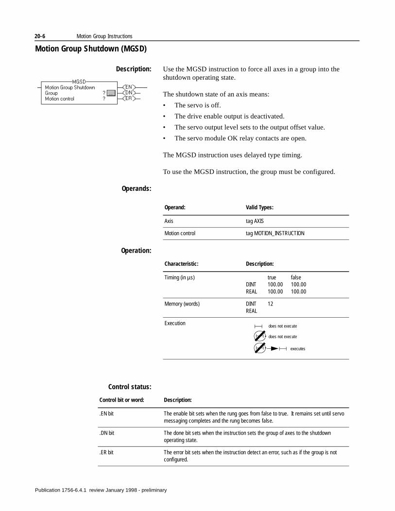
20-6 Motion Group Instructions
Motion Group Shutdown (MGSD)
Description: Use the MGSD instruction to force all axes in a group into the shutdown operating state.
The shutdown state of an axis means:
• The servo is off.
• The drive enable output is deactivated.
• The servo output level sets to the output offset value.
• The servo module OK relay contacts are open.
The MGSD instruction uses delayed type timing.
To use the MGSD instruction, the group must be configured.
Operands:
Operation:
Control status:
Operand: Valid Types:
Axis tag AXIS
Motion control tag MOTION_INSTRUCTION
Characteristic: Description:
Timing (in µs) true falseDINT 100.00 100.00REAL 100.00 100.00
Memory (words) DINT 12REAL
Execution does not execute
does not execute
executes
Control bit or word: Description:
.EN bit The enable bit sets when the rung goes from false to true. It remains set until servo messaging completes and the rung becomes false.
.DN bit The done bit sets when the instruction sets the group of axes to the shutdown operating state.
.ER bit The error bit sets when the instruction detect an error, such as if the group is not configured.
Publication 1756-6.4.1 review January 1998 - preliminary
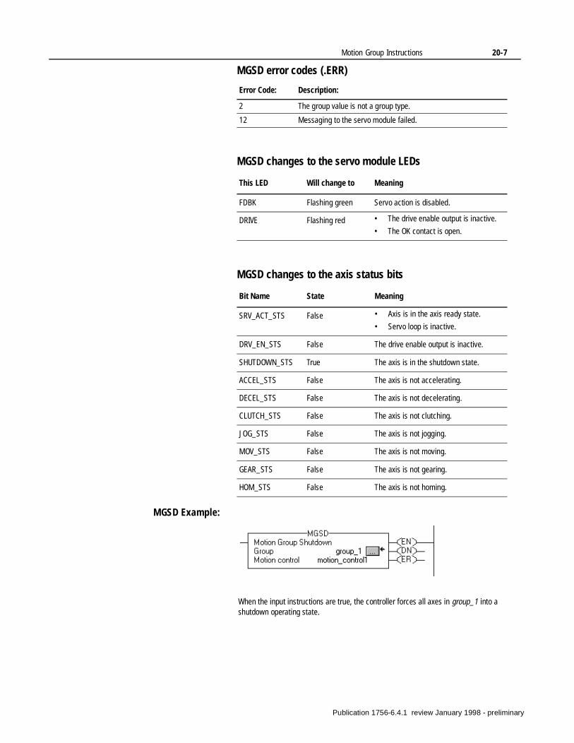
Motion Group Instructions 20-7
MGSD error codes (.ERR)
MGSD changes to the servo module LEDs
MGSD changes to the axis status bits
MGSD Example:
Error Code: Description:
2 The group value is not a group type.
12 Messaging to the servo module failed.
This LED Will change to Meaning
FDBK Flashing green Servo action is disabled.
DRIVE Flashing red • The drive enable output is inactive.
• The OK contact is open.
Bit Name State Meaning
SRV_ACT_STS False • Axis is in the axis ready state.
• Servo loop is inactive.
DRV_EN_STS False The drive enable output is inactive.
SHUTDOWN_STS True The axis is in the shutdown state.
ACCEL_STS False The axis is not accelerating.
DECEL_STS False The axis is not decelerating.
CLUTCH_STS False The axis is not clutching.
JOG_STS False The axis is not jogging.
MOV_STS False The axis is not moving.
GEAR_STS False The axis is not gearing.
HOM_STS False The axis is not homing.
When the input instructions are true, the controller forces all axes in group_1 into a shutdown operating state.
Publication 1756-6.4.1 review January 1998 - preliminary
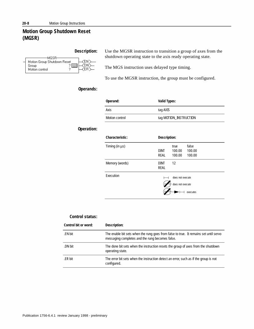
20-8 Motion Group Instructions
Motion Group Shutdown Reset (MGSR)
Description: Use the MGSR instruction to transition a group of axes from the shutdown operating state to the axis ready operating state.
The MGS instruction uses delayed type timing.
To use the MGSR instruction, the group must be configured.
Operands:
Operation:
Control status:
Operand: Valid Types:
Axis tag AXIS
Motion control tag MOTION_INSTRUCTION
Characteristic: Description:
Timing (in µs) true falseDINT 100.00 100.00REAL 100.00 100.00
Memory (words) DINT 12REAL
Execution does not execute
does not execute
executes
Control bit or word: Description:
.EN bit The enable bit sets when the rung goes from false to true. It remains set until servo messaging completes and the rung becomes false.
.DN bit The done bit sets when the instruction resets the group of axes from the shutdown operating state.
.ER bit The error bit sets when the instruction detect an error, such as if the group is not configured.
Publication 1756-6.4.1 review January 1998 - preliminary
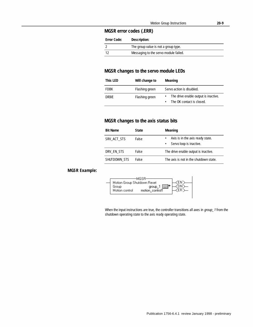
Motion Group Instructions 20-9
MGSR error codes (.ERR)
MGSR changes to the servo module LEDs
MGSR changes to the axis status bits
MGSR Example:
Error Code: Description:
2 The group value is not a group type.
12 Messaging to the servo module failed.
This LED Will change to Meaning
FDBK Flashing green Servo action is disabled.
DRIVE Flashing green • The drive enable output is inactive.
• The OK contact is closed.
Bit Name State Meaning
SRV_ACT_STS False • Axis is in the axis ready state.
• Servo loop is inactive.
DRV_EN_STS False The drive enable output is inactive.
SHUTDOWN_STS False The axis is not in the shutdown state.
When the input instructions are true, the controller transitions all axes in group_1 from the shutdown operating state to the axis ready operating state.
Publication 1756-6.4.1 review January 1998 - preliminary
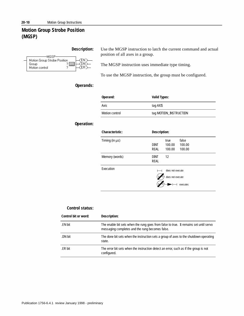
20-10 Motion Group Instructions
Motion Group Strobe Position (MGSP)
Description: Use the MGSP instruction to latch the current command and actual position of all axes in a group.
The MGSP instruction uses immediate type timing.
To use the MGSP instruction, the group must be configured.
Operands:
Operation:
Control status:
Operand: Valid Types:
Axis tag AXIS
Motion control tag MOTION_INSTRUCTION
Characteristic: Description:
Timing (in µs) true falseDINT 100.00 100.00REAL 100.00 100.00
Memory (words) DINT 12REAL
Execution does not execute
does not execute
executes
Control bit or word: Description:
.EN bit The enable bit sets when the rung goes from false to true. It remains set until servo messaging completes and the rung becomes false.
.DN bit The done bit sets when the instruction sets a group of axes to the shutdown operating state.
.ER bit The error bit sets when the instruction detect an error, such as if the group is not configured.
Publication 1756-6.4.1 review January 1998 - preliminary
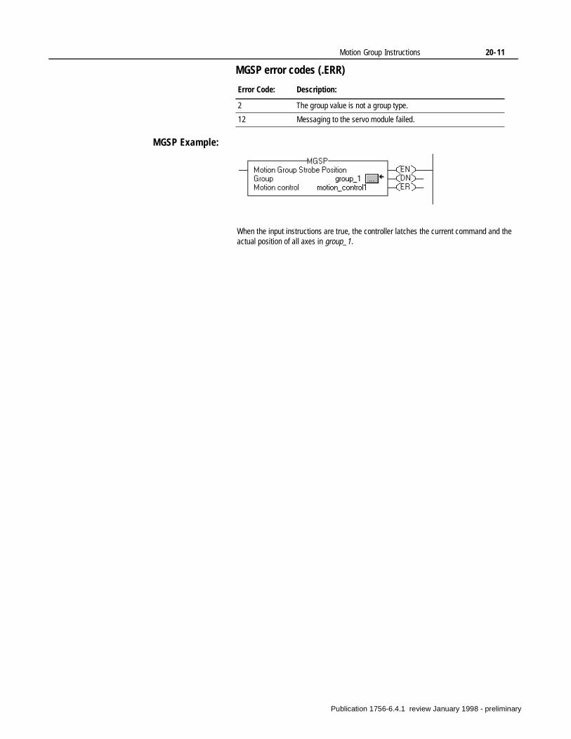
Motion Group Instructions 20-11
MGSP error codes (.ERR)
MGSP Example:
Error Code: Description:
2 The group value is not a group type.
12 Messaging to the servo module failed.
When the input instructions are true, the controller latches the current command and the actual position of all axes in group_1.
Publication 1756-6.4.1 review January 1998 - preliminary

20-12 Motion Group Instructions
Notes:
Publication 1756-6.4.1 review January 1998 - preliminary
Chapter21
Motion Event Instructions(MAW, MDW, MAR, MDR)
Introduction Motion event instructions control the arming and disarming of special event checking functions, such as registration and watch position. The motion event instructions are:
If you want to: Use this instruction: See page:
Arm watch-position event-checking for an axis.
MAW 21-2
Disarm watch-position event-checking for an axis.
MDW 21-4
Arm servo-module registration-event checking for an axis.
MAR 21-6
Disarm servo-module registration-event checking for an axis.
MDR 21-9
Publication 1756-6.4.1 review January 1998 - preliminary
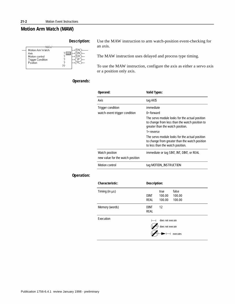
21-2 Motion Event Instructions
Motion Arm Watch (MAW)
Description: Use the MAW instruction to arm watch-position event-checking for an axis.
The MAW instruction uses delayed and process type timing.
To use the MAW instruction, configure the axis as either a servo axis or a position only axis.
Operands:
Operation:
Operand: Valid Types:
Axis tag AXIS
Trigger condition
watch-event trigger condition
immediate
0=forward
The servo module looks for the actual position to change from less than the watch position to greater than the watch position.
1=reverse
The servo module looks for the actual position to change from greater than the watch position to less than the watch position.
Watch position
new value for the watch position
immediate or tag SINT, INT, DINT, or REAL
Motion control tag MOTION_INSTRUCTION
Characteristic: Description:
Timing (in µs) true falseDINT 100.00 100.00REAL 100.00 100.00
Memory (words) DINT 12REAL
Execution does not execute
does not execute
executes
Publication 1756-6.4.1 review January 1998 - preliminary
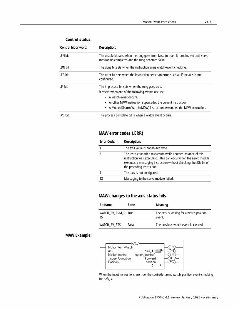
Motion Event Instructions 21-3
Control status:
MAW error codes (.ERR)
MAW changes to the axis status bits
MAW Example:
Control bit or word: Description:
.EN bit The enable bit sets when the rung goes from false to true. It remains set until servo messaging completes and the rung becomes false.
.DN bit The done bit sets when the instruction arms watch-event checking.
.ER bit The error bit sets when the instruction detect an error, such as if the axis is not configured.
.IP bit The in process bit sets when the rung goes true.
It resets when one of the following events occurs:
• A watch event occurs.
• Another MAW instruction supersedes the current instruction.
• A Motion Disarm Watch (MDW) instruction terminates the MAW instruction.
.PC bit The process complete bit is when a watch event occurs.
Error Code: Description:
1 The axis value is not an axis type.
3 The instruction tried to execute while another instance of this instruction was executing. This can occur when the servo module executes a messaging instruction without checking the .DN bit of the preceding instruction.
11 The axis is not configured.
12 Messaging to the servo module failed.
Bit Name State Meaning
WATCH_EV_ARM_STS
True The axis is looking for a watch position event.
WATCH_EV_STS False The previous watch event is cleared.
When the input instructions are true, the controller arms watch-position event-checking for axis_1.
Publication 1756-6.4.1 review January 1998 - preliminary
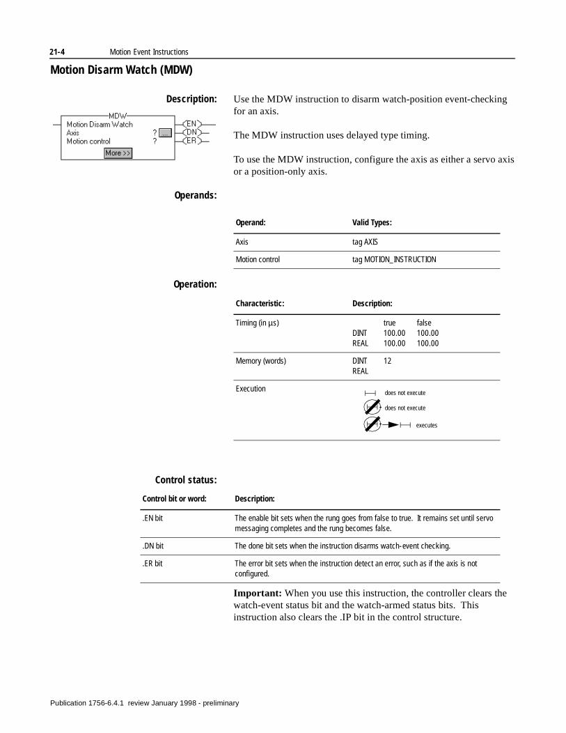
21-4 Motion Event Instructions
Motion Disarm Watch (MDW)
Description: Use the MDW instruction to disarm watch-position event-checking for an axis.
The MDW instruction uses delayed type timing.
To use the MDW instruction, configure the axis as either a servo axis or a position-only axis.
Operands:
Operation:
Control status:
Important: When you use this instruction, the controller clears the watch-event status bit and the watch-armed status bits. This instruction also clears the .IP bit in the control structure.
Operand: Valid Types:
Axis tag AXIS
Motion control tag MOTION_INSTRUCTION
Characteristic: Description:
Timing (in µs) true falseDINT 100.00 100.00REAL 100.00 100.00
Memory (words) DINT 12REAL
Execution does not execute
does not execute
executes
Control bit or word: Description:
.EN bit The enable bit sets when the rung goes from false to true. It remains set until servo messaging completes and the rung becomes false.
.DN bit The done bit sets when the instruction disarms watch-event checking.
.ER bit The error bit sets when the instruction detect an error, such as if the axis is not configured.
Publication 1756-6.4.1 review January 1998 - preliminary
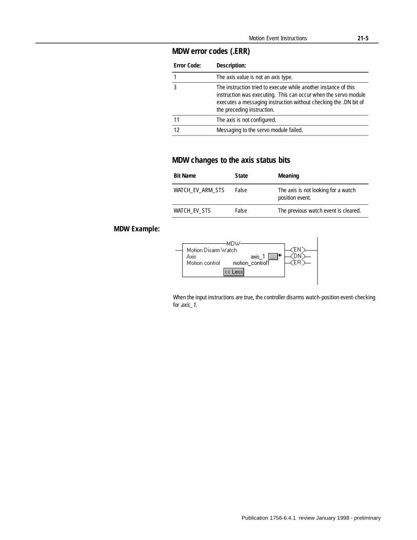
Motion Event Instructions 21-5
MDW error codes (.ERR)
MDW changes to the axis status bits
MDW Example:
Error Code: Description:
1 The axis value is not an axis type.
3 The instruction tried to execute while another instance of this instruction was executing. This can occur when the servo module executes a messaging instruction without checking the .DN bit of the preceding instruction.
11 The axis is not configured.
12 Messaging to the servo module failed.
Bit Name State Meaning
WATCH_EV_ARM_STS False The axis is not looking for a watch position event.
WATCH_EV_STS False The previous watch event is cleared.
When the input instructions are true, the controller disarms watch-position event-checking for axis_1.
Publication 1756-6.4.1 review January 1998 - preliminary
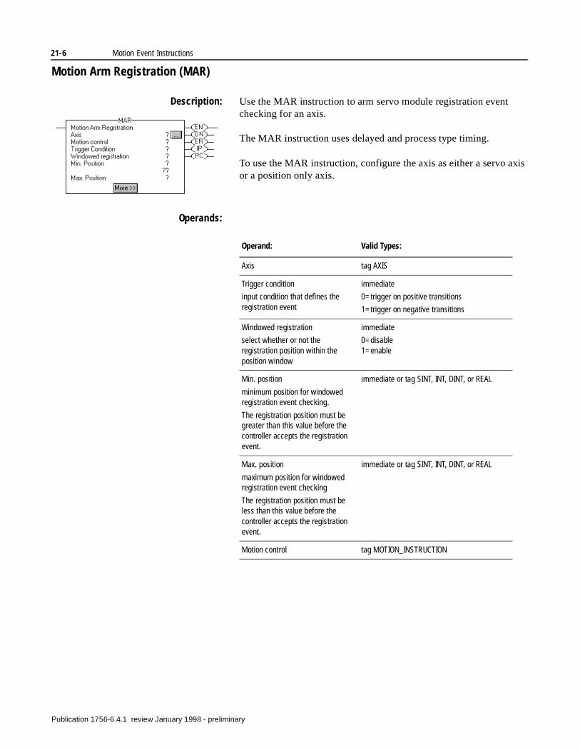
21-6 Motion Event Instructions
Motion Arm Registration (MAR)
Description: Use the MAR instruction to arm servo module registration event checking for an axis.
The MAR instruction uses delayed and process type timing.
To use the MAR instruction, configure the axis as either a servo axis or a position only axis.
Operands:
Operand: Valid Types:
Axis tag AXIS
Trigger condition
input condition that defines the registration event
immediate
0=trigger on positive transitions
1=trigger on negative transitions
Windowed registration
select whether or not the registration position within the position window
immediate
0=disable1=enable
Min. position
minimum position for windowed registration event checking.
The registration position must be greater than this value before the controller accepts the registration event.
immediate or tag SINT, INT, DINT, or REAL
Max. position
maximum position for windowed registration event checking
The registration position must be less than this value before the controller accepts the registration event.
immediate or tag SINT, INT, DINT, or REAL
Motion control tag MOTION_INSTRUCTION
Publication 1756-6.4.1 review January 1998 - preliminary
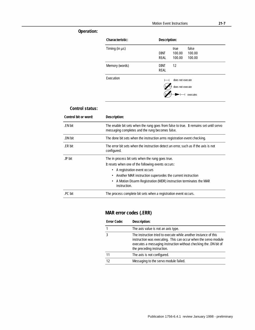
Motion Event Instructions 21-7
Operation:
Control status:
MAR error codes (.ERR)
Characteristic: Description:
Timing (in µs) true falseDINT 100.00 100.00REAL 100.00 100.00
Memory (words) DINT 12REAL
Execution does not execute
does not execute
executes
Control bit or word: Description:
.EN bit The enable bit sets when the rung goes from false to true. It remains set until servo messaging completes and the rung becomes false.
.DN bit The done bit sets when the instruction arms registration event checking.
.ER bit The error bit sets when the instruction detect an error, such as if the axis is not configured.
.IP bit The in process bit sets when the rung goes true.
It resets when one of the following events occurs:
• A registration event occurs
• Another MAR instruction supersedes the current instruction
• A Motion Disarm Registration (MDR) instruction terminates the MAR instruction.
.PC bit The process complete bit sets when a registration event occurs.
Error Code: Description:
1 The axis value is not an axis type.
3 The instruction tried to execute while another instance of this instruction was executing. This can occur when the servo module executes a messaging instruction without checking the .DN bit of the preceding instruction.
11 The axis is not configured.
12 Messaging to the servo module failed.
Publication 1756-6.4.1 review January 1998 - preliminary
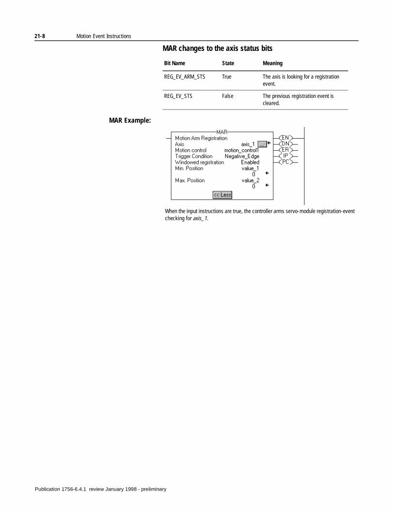
21-8 Motion Event Instructions
MAR changes to the axis status bits
MAR Example:
Bit Name State Meaning
REG_EV_ARM_STS True The axis is looking for a registration event.
REG_EV_STS False The previous registration event is cleared.
When the input instructions are true, the controller arms servo-module registration-event checking for axis_1.
Publication 1756-6.4.1 review January 1998 - preliminary
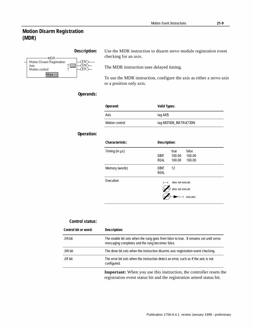
Motion Event Instructions 21-9
Motion Disarm Registration (MDR)
Description: Use the MDR instruction to disarm servo module registration event checking for an axis.
The MDR instruction uses delayed timing.
To use the MDR instruction, configure the axis as either a servo axis or a position only axis.
Operands:
Operation:
Control status:
Important: When you use this instruction, the controller resets the registration event status bit and the registration armed status bit.
Operand: Valid Types:
Axis tag AXIS
Motion control tag MOTION_INSTRUCTION
Characteristic: Description:
Timing (in µs) true falseDINT 100.00 100.00REAL 100.00 100.00
Memory (words) DINT 12REAL
Execution does not execute
does not execute
executes
Control bit or word: Description:
.EN bit The enable bit sets when the rung goes from false to true. It remains set until servo messaging completes and the rung becomes false.
.DN bit The done bit sets when the instruction disarms axis-registration event checking.
.ER bit The error bit sets when the instruction detect an error, such as if the axis is not configured.
Publication 1756-6.4.1 review January 1998 - preliminary
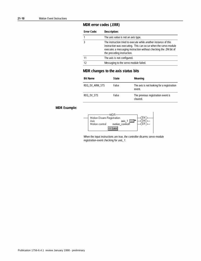
21-10 Motion Event Instructions
MDR error codes (.ERR)
MDR changes to the axis status bits
MDR Example:
Error Code: Description:
1 The axis value is not an axis type.
3 The instruction tried to execute while another instance of this instruction was executing. This can occur when the servo module executes a messaging instruction without checking the .DN bit of the preceding instruction.
11 The axis is not configured.
12 Messaging to the servo module failed.
Bit Name State Meaning
REG_EV_ARM_STS False The axis is not looking for a registration event.
REG_EV_STS False The previous registration event is cleared.
When the input instructions are true, the controller disarms servo-module registration-event checking for axis_1.
Publication 1756-6.4.1 review January 1998 - preliminary
Chapter22
Motion Configuration Instructions(MAAT, MRAT, MAHD, MRHD)
Introduction Use the motion configuration instructions to tune an axis and to run diagnostic tests for the servo system. These tests include:
• A motor encoder hookup test.
• An encoder hookup test.
• A marker test
The motion configuration instructions are:
If you want to: Use this instruction: See page:
Compute a complete set of servo gains and dynamic limits based on a previously executed MRAT instruction.
The MAAT instruction also updates the servo module with the new gain parameters.
MAAT 22-2
Command the servo module to run a tuning motion profile for an axis.
MRAT 22-4
Apply the results of a previously executed MRHD instruction.
The MAHD instruction generates a new set of encoder and servo polarities based on the observed direction of motion during the MRHD instruction.
MAHD 22-7
Command the servo module to run one of four diagnostic tests on an axis.
MRHD 22-9
Publication 1756-6.4.1 review January 1998 - preliminary
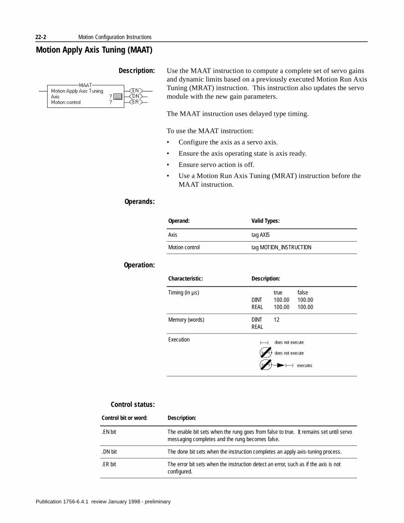
22-2 Motion Configuration Instructions
Motion Apply Axis Tuning (MAAT)
Description: Use the MAAT instruction to compute a complete set of servo gains and dynamic limits based on a previously executed Motion Run Axis Tuning (MRAT) instruction. This instruction also updates the servo module with the new gain parameters.
The MAAT instruction uses delayed type timing.
To use the MAAT instruction:
• Configure the axis as a servo axis.
• Ensure the axis operating state is axis ready.
• Ensure servo action is off.
• Use a Motion Run Axis Tuning (MRAT) instruction before the MAAT instruction.
Operands:
Operation:
Control status:
Operand: Valid Types:
Axis tag AXIS
Motion control tag MOTION_INSTRUCTION
Characteristic: Description:
Timing (in µs) true falseDINT 100.00 100.00REAL 100.00 100.00
Memory (words) DINT 12REAL
Execution does not execute
does not execute
executes
Control bit or word: Description:
.EN bit The enable bit sets when the rung goes from false to true. It remains set until servo messaging completes and the rung becomes false.
.DN bit The done bit sets when the instruction completes an apply axis-tuning process.
.ER bit The error bit sets when the instruction detect an error, such as if the axis is not configured.
Publication 1756-6.4.1 review January 1998 - preliminary
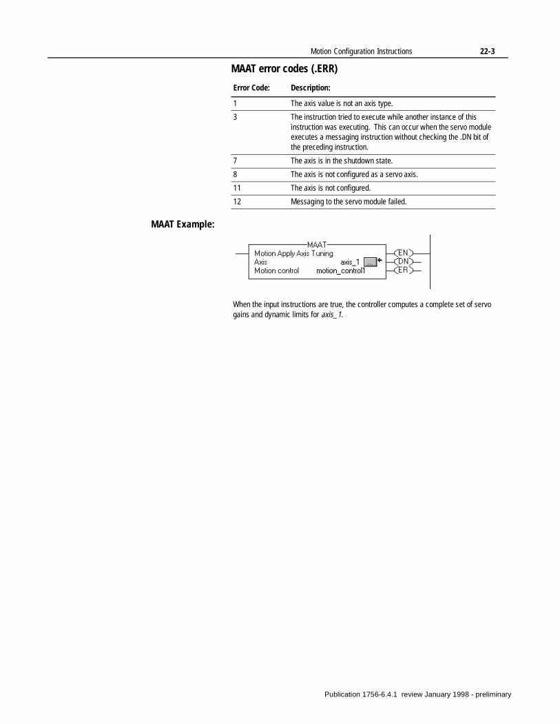
Motion Configuration Instructions 22-3
MAAT error codes (.ERR)
MAAT Example:
Error Code: Description:
1 The axis value is not an axis type.
3 The instruction tried to execute while another instance of this instruction was executing. This can occur when the servo module executes a messaging instruction without checking the .DN bit of the preceding instruction.
7 The axis is in the shutdown state.
8 The axis is not configured as a servo axis.
11 The axis is not configured.
12 Messaging to the servo module failed.
When the input instructions are true, the controller computes a complete set of servo gains and dynamic limits for axis_1.
Publication 1756-6.4.1 review January 1998 - preliminary
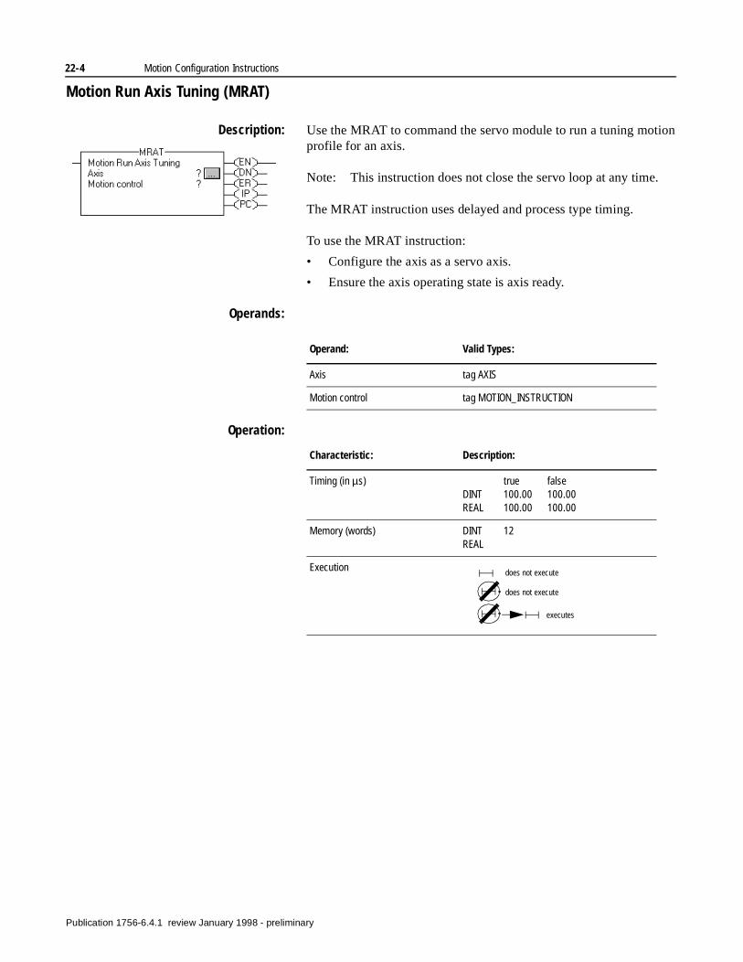
22-4 Motion Configuration Instructions
Motion Run Axis Tuning (MRAT)
Description: Use the MRAT to command the servo module to run a tuning motion profile for an axis.
Note: This instruction does not close the servo loop at any time.
The MRAT instruction uses delayed and process type timing.
To use the MRAT instruction:
• Configure the axis as a servo axis.
• Ensure the axis operating state is axis ready.
Operands:
Operation:
Operand: Valid Types:
Axis tag AXIS
Motion control tag MOTION_INSTRUCTION
Characteristic: Description:
Timing (in µs) true falseDINT 100.00 100.00REAL 100.00 100.00
Memory (words) DINT 12REAL
Execution does not execute
does not execute
executes
Publication 1756-6.4.1 review January 1998 - preliminary
Motion Configuration Instructions 22-5
Control status:
MRAT error codes (.ERR)
MRAT changes to the axis status bits
Control bit or word: Description:
.EN bit The enable bit sets when the rung goes from false to true. It remains set until servo messaging completes and the rung becomes false.
.DN bit The done bit sets when the instruction initiates a tuning process.
.ER bit The error bit sets when the instruction detect an error, such as if the axis is not configured.
In process (IP) The in process bit sets when the rung goes true.
It resets when one of the following events occurs:
• The MRAT instruction completes.
• A Motion Axis Stop (MAS) instruction or a servo fault terminates the MRAT instruction.
Process complete (PC) The process complete bit sets when the instruction completes a tuning process.
Error Code: Description:
1 The axis value is not an axis type.
3 The instruction tried to execute while another instance of this instruction was executing. This can occur when the servo module executes a messaging instruction without checking the .DN bit of the preceding instruction.
4 The axis servo loop is closed.
6 The axis drive is enabled.
7 The axis is in the shutdown state.
8 The axis is not configured as a servo axis.
11 The axis is not configured.
12 Messaging to the servo module failed.
Bit Name State Meaning
DRV_EN_STS True • The axis is in the drive control state.
• The drive enable output is active while the tuning profile is running.
TUNE_STS True The axis is running a tuning process.
Publication 1756-6.4.1 review January 1998 - preliminary
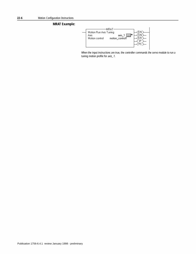
22-6 Motion Configuration Instructions
MRAT Example:
When the input instructions are true, the controller commands the servo module to run a tuning motion profile for axis_1.
Publication 1756-6.4.1 review January 1998 - preliminary
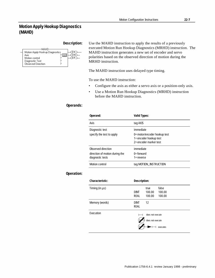
Motion Configuration Instructions 22-7
s.
Motion Apply Hookup Diagnostics (MAHD)
Description: Use the MAHD instruction to apply the results of a previously executed Motion Run Hookup Diagnostics (MRHD) instruction. The MAHD instruction generates a new set of encoder and servo polarities based on the observed direction of motion during the MRHD instruction.
The MAHD instruction uses delayed type timing.
To use the MAHD instruction:
• Configure the axis as either a servo axis or a position-only axi
• Use a Motion Run Hookup Diagnostics (MRHD) instruction before the MAHD instruction.
Operands:
Operation:
Operand: Valid Types:
Axis tag AXIS
Diagnostic test
specify the test to apply
immediate
0=motor/encoder hookup test1=encoder hookup test2=encoder marker test
Observed direction
direction of motion during the diagnostic tests
immediate
0=forward 1=reverse
Motion control tag MOTION_INSTRUCTION
Characteristic: Description:
Timing (in µs) true falseDINT 100.00 100.00REAL 100.00 100.00
Memory (words) DINT 12REAL
Execution does not execute
does not execute
executes
Publication 1756-6.4.1 review January 1998 - preliminary
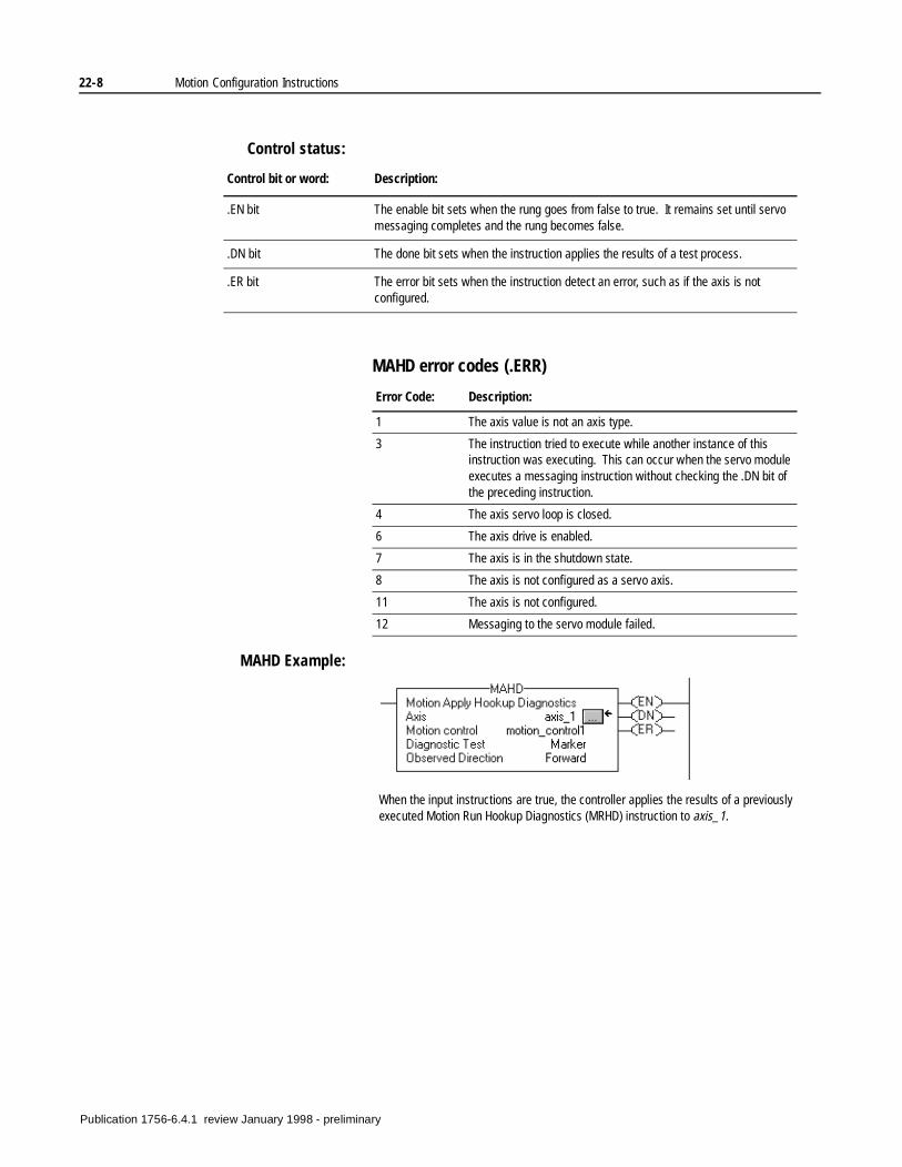
22-8 Motion Configuration Instructions
Control status:
MAHD error codes (.ERR)
MAHD Example:
Control bit or word: Description:
.EN bit The enable bit sets when the rung goes from false to true. It remains set until servo messaging completes and the rung becomes false.
.DN bit The done bit sets when the instruction applies the results of a test process.
.ER bit The error bit sets when the instruction detect an error, such as if the axis is not configured.
Error Code: Description:
1 The axis value is not an axis type.
3 The instruction tried to execute while another instance of this instruction was executing. This can occur when the servo module executes a messaging instruction without checking the .DN bit of the preceding instruction.
4 The axis servo loop is closed.
6 The axis drive is enabled.
7 The axis is in the shutdown state.
8 The axis is not configured as a servo axis.
11 The axis is not configured.
12 Messaging to the servo module failed.
When the input instructions are true, the controller applies the results of a previously executed Motion Run Hookup Diagnostics (MRHD) instruction to axis_1.
Publication 1756-6.4.1 review January 1998 - preliminary
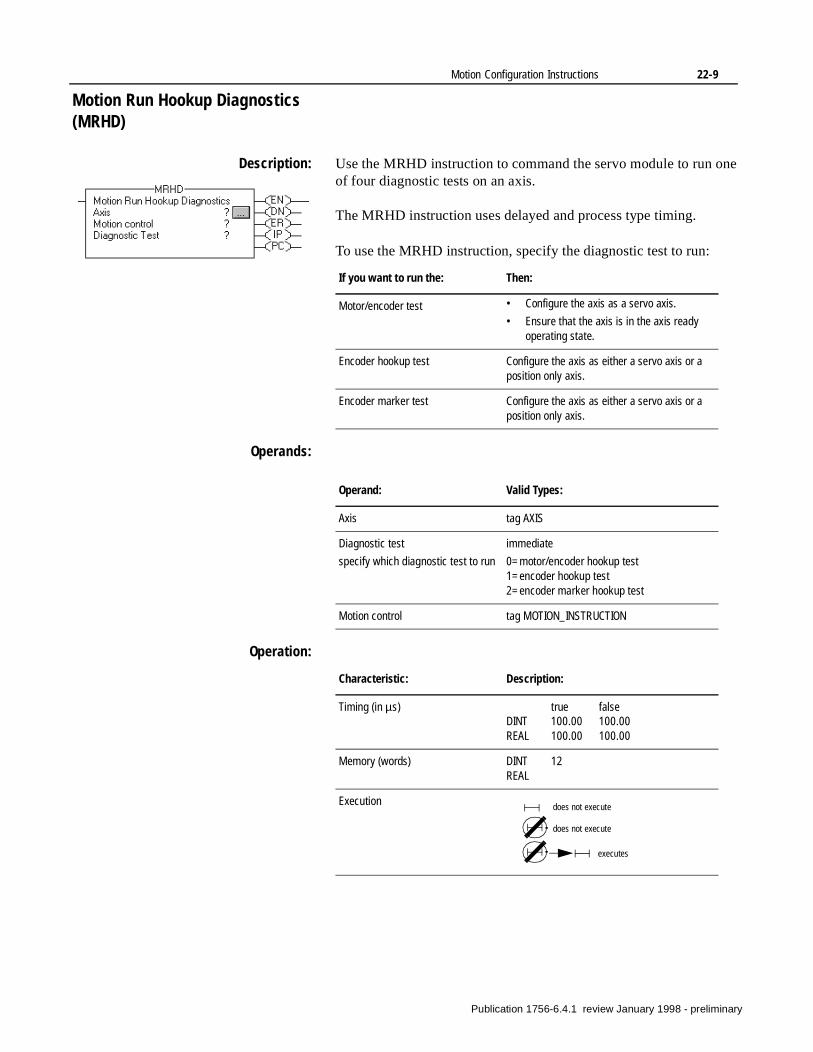
Motion Configuration Instructions 22-9
Motion Run Hookup Diagnostics (MRHD)
Description: Use the MRHD instruction to command the servo module to run one of four diagnostic tests on an axis.
The MRHD instruction uses delayed and process type timing.
To use the MRHD instruction, specify the diagnostic test to run:
Operands:
Operation:
If you want to run the: Then:
Motor/encoder test • Configure the axis as a servo axis.
• Ensure that the axis is in the axis ready operating state.
Encoder hookup test Configure the axis as either a servo axis or a position only axis.
Encoder marker test Configure the axis as either a servo axis or a position only axis.
Operand: Valid Types:
Axis tag AXIS
Diagnostic test
specify which diagnostic test to run
immediate
0=motor/encoder hookup test1=encoder hookup test2=encoder marker hookup test
Motion control tag MOTION_INSTRUCTION
Characteristic: Description:
Timing (in µs) true falseDINT 100.00 100.00REAL 100.00 100.00
Memory (words) DINT 12REAL
Execution does not execute
does not execute
executes
Publication 1756-6.4.1 review January 1998 - preliminary
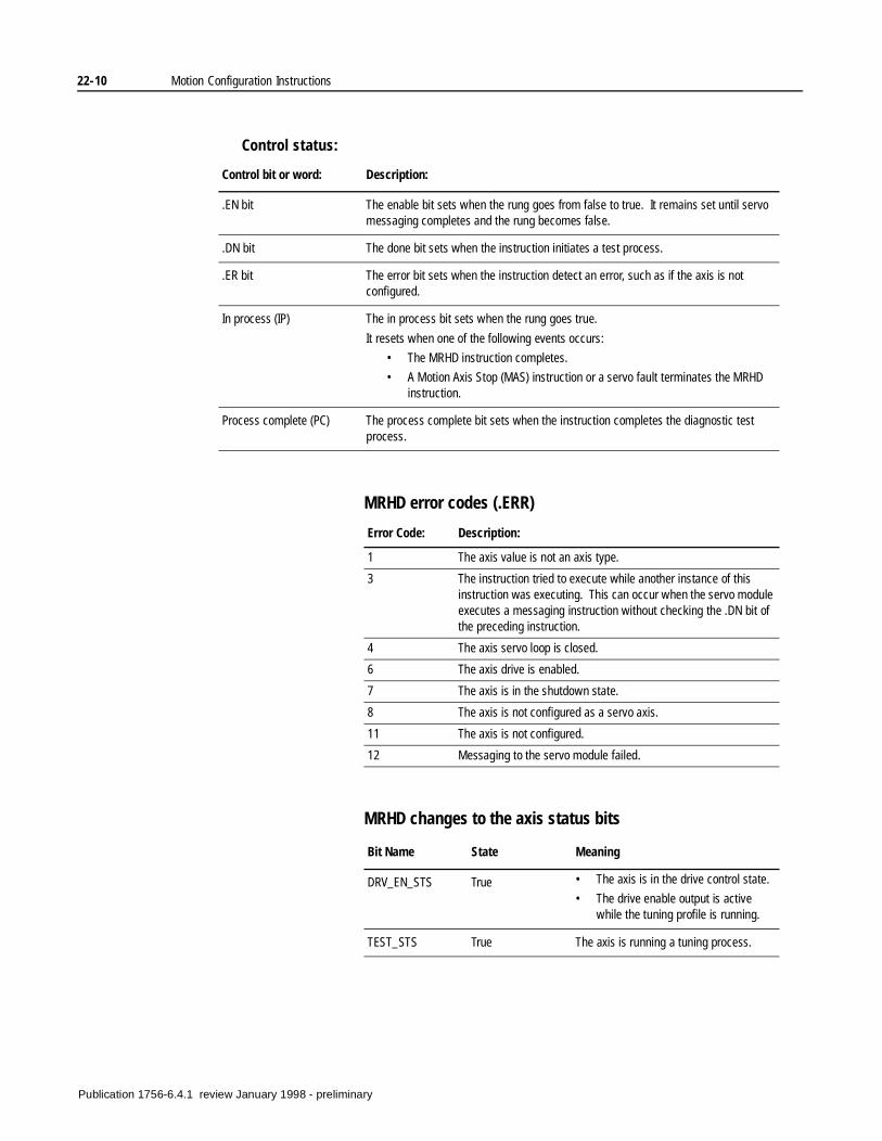
22-10 Motion Configuration Instructions
Control status:
MRHD error codes (.ERR)
MRHD changes to the axis status bits
Control bit or word: Description:
.EN bit The enable bit sets when the rung goes from false to true. It remains set until servo messaging completes and the rung becomes false.
.DN bit The done bit sets when the instruction initiates a test process.
.ER bit The error bit sets when the instruction detect an error, such as if the axis is not configured.
In process (IP) The in process bit sets when the rung goes true.
It resets when one of the following events occurs:
• The MRHD instruction completes.
• A Motion Axis Stop (MAS) instruction or a servo fault terminates the MRHD instruction.
Process complete (PC) The process complete bit sets when the instruction completes the diagnostic test process.
Error Code: Description:
1 The axis value is not an axis type.
3 The instruction tried to execute while another instance of this instruction was executing. This can occur when the servo module executes a messaging instruction without checking the .DN bit of the preceding instruction.
4 The axis servo loop is closed.
6 The axis drive is enabled.
7 The axis is in the shutdown state.
8 The axis is not configured as a servo axis.
11 The axis is not configured.
12 Messaging to the servo module failed.
Bit Name State Meaning
DRV_EN_STS True • The axis is in the drive control state.
• The drive enable output is active while the tuning profile is running.
TEST_STS True The axis is running a tuning process.
Publication 1756-6.4.1 review January 1998 - preliminary

Motion Configuration Instructions 22-11
Example:
When the input instructions are true, the controller runs the encoder diagnostic test on axis
Publication 1756-6.4.1 review January 1998 - preliminary

22-12 Motion Configuration Instructions
Notes:
Publication 1756-6.4.1 review January 1998 - preliminary