AIR FORCE MANUAL 15-111 OF THE AIR FORCE 12 MARCH … · by order of the secretary of the air force...
106
BY ORDER OF THE SECRETARY OF THE AIR FORCE AIR FORCE MANUAL 15-111 12 MARCH 2019 Weather SURFACE WEATHER OBSERVATIONS COMPLIANCE WITH THIS PUBLICATION IS MANDATORY ACCESSIBILITY: This publication is available digitally on the e-Publishing website at www.e-Publishing.af.mil for downloading or ordering RELEASABILITY: There are no releasability restrictions on this publication OPR: HQ USAF/A3WP Supersedes: AFMAN15-111, 27 February 2013 Certified by: HQ USAF/A3W (Mr. Ralph O. Stoffler) Pages: 106 This manual implements Air Force (AF) Policy Directive (AFPD) 15-1, Weather Operations. It also implements World Meteorological Organization (WMO) Manual on Codes, No. 306, Volume I.1 and Volume II. It prescribes basic observing fundamentals and terms and establishes aviation code forms for recording and disseminating weather observations. This publication applies to all Regular Air Force, Air Force Reserve and Air National Guard organizations with assigned weather personnel, and to the uniformed members, civilian employees and contractors assigned thereto. This AF Manual (AFMAN) may be supplemented at any level, but all supplements that directly implement this publication must be routed to the office of primary responsibility (OPR) for coordination prior to certification and approval. Refer recommended changes and questions about this publication to the Office of Primary Responsibility (OPR) using the AF Form 847, Recommendation for Change of Publication; route AF Forms 847 from the field through the appropriate functional chain of command. The authorities to waive wing/organization level requirements in this publication are identified with a Tier (“T-0, T-1, T-2, T-3”) number following the compliance statement. See AFI 33-360, Publications and Forms Management, for a description of the authorities associated with the Tier numbers. Submit requests for waivers through the chain of command to the appropriate Tier waiver approval authority, or alternately, to this publications’ OPR for non-tiered compliance items. Ensure all records created as a result of processes prescribed in this publication are maintained in accordance with Air Force Manual 33-363, Management of Records, and disposed of in accordance with the Air Force Records Disposition Schedule located in the Air Force Records Information Management System. The use of the name or mark of any
Transcript of AIR FORCE MANUAL 15-111 OF THE AIR FORCE 12 MARCH … · by order of the secretary of the air force...

BY ORDER OF THE SECRETARY
OF THE AIR FORCE
AIR FORCE MANUAL 15-111
12 MARCH 2019
Weather
SURFACE WEATHER OBSERVATIONS
COMPLIANCE WITH THIS PUBLICATION IS MANDATORY
ACCESSIBILITY: This publication is available digitally on the e-Publishing website at
www.e-Publishing.af.mil for downloading or ordering
RELEASABILITY: There are no releasability restrictions on this publication
OPR: HQ USAF/A3WP
Supersedes: AFMAN15-111,
27 February 2013
Certified by: HQ USAF/A3W
(Mr. Ralph O. Stoffler)
Pages: 106
This manual implements Air Force (AF) Policy Directive (AFPD) 15-1, Weather Operations. It
also implements World Meteorological Organization (WMO) Manual on Codes, No. 306, Volume
I.1 and Volume II. It prescribes basic observing fundamentals and terms and establishes aviation
code forms for recording and disseminating weather observations. This publication applies to all
Regular Air Force, Air Force Reserve and Air National Guard organizations with assigned weather
personnel, and to the uniformed members, civilian employees and contractors assigned thereto.
This AF Manual (AFMAN) may be supplemented at any level, but all supplements that directly
implement this publication must be routed to the office of primary responsibility (OPR) for
coordination prior to certification and approval. Refer recommended changes and questions about
this publication to the Office of Primary Responsibility (OPR) using the AF Form 847,
Recommendation for Change of Publication; route AF Forms 847 from the field through the
appropriate functional chain of command. The authorities to waive wing/organization level
requirements in this publication are identified with a Tier (“T-0, T-1, T-2, T-3”) number following
the compliance statement. See AFI 33-360, Publications and Forms Management, for a description
of the authorities associated with the Tier numbers. Submit requests for waivers through the chain
of command to the appropriate Tier waiver approval authority, or alternately, to this publications’
OPR for non-tiered compliance items. Ensure all records created as a result of processes prescribed
in this publication are maintained in accordance with Air Force Manual 33-363, Management of
Records, and disposed of in accordance with the Air Force Records Disposition Schedule located
in the Air Force Records Information Management System. The use of the name or mark of any

2 AFMAN15-111 12 MARCH 2019
specific manufacturer, commercial product, commodity or service in this publication does not
imply endorsement by the AF.
SUMMARY OF CHANGES
This document has been substantially revised and needs to be completely reviewed. Major changes
include the addition of roles and responsibilities and the reorganization of weather elements into
respective chapters. The majority of operations have not changed but this manual must be read in
entirety because of its restructure.
Chapter 1— OVERVIEW 7
1.1. General. .................................................................................................................. 7
1.2. The procedures in this manual apply to all AF Weather organizations or
associated contractors performing weather observing in support of AF, Army, or
DoD wide operations. ............................................................................................. 7
1.3. The AN/FMQ-19, AN/FMQ-22 and AN/FMQ-23 are certified AF fixed base
weather observing systems (FBWOS). ................................................................... 7
Chapter 2— ROLES AND RESPONSIBILITIES 8
2.1. AF/A3W will process all T-0 waiver requests submitted by Air Force Weather
organizations. .......................................................................................................... 8
2.2. WF/Det Leadership will: ........................................................................................ 8
2.3. WF/Det technicians responsible for preparing weather observations will: ........... 9
Chapter 3— REPORTING AND ENCODING WEATHER OBSERVATIONS 10
3.1. Aviation Weather Code Forms. ............................................................................. 10
3.2. METAR/SPECI Code Format. ............................................................................... 11
Figure 3.1. Automated/Augmented METAR/SPECI Code. ...................................................... 12
3.3. Coding METAR or SPECI Reports. ...................................................................... 12
3.4. Coding Missing Data in METAR and SPECI Reports. ......................................... 13
3.5. Remarks (RMK). ................................................................................................... 13
3.6. Observation Methods. ............................................................................................. 14
3.7. Magnetic Declination. ............................................................................................ 15
3.8. Unofficial Weather Reports. .................................................................................. 15
3.9. Modes of Observation. ........................................................................................... 15

AFMAN15-111 12 MARCH 2019 3
3.10. Rounding of Figures and Values. ........................................................................... 15
3.11. Dissemination. ....................................................................................................... 16
Figure 3.2. Examples of Augmented Longline Dissemination of METARs/SPECIs. .............. 17
3.12. Longline Dissemination by other WFs/Dets. ......................................................... 18
3.13. Reports of a Volcanic Eruption. ............................................................................. 18
Chapter 4— GENERAL OBSERVING INFORMATION 19
4.1. General. .................................................................................................................. 19
4.2. FBWOS. ................................................................................................................. 19
4.3. Automated Dissemination System (ADS). ............................................................ 19
4.4. FBWOS Certification Requirements. ..................................................................... 20
4.5. Position Qualification Requirements. .................................................................... 21
4.6. Station Information File. ........................................................................................ 21
4.7. Accuracy of Time. ................................................................................................. 21
4.8. Alternate Operating Location (AOL). .................................................................... 21
4.9. Cooperative Weather Watch. ................................................................................. 22
4.10. Control Tower Observations ................................................................................... 22
4.11. Observing Aids for Visibility. ................................................................................ 22
Figure 4.1. Example Visibility Checkpoint Photograph. .......................................................... 23
4.12. Aircraft Mishap. ..................................................................................................... 23
4.13. Inactive/Parallel Runway Equipment. ................................................................... 24
Chapter 5— OBSERVATION AUGMENTATION 25
5.1. General. .................................................................................................................. 25
5.2. Supplementing FBWOSs. ...................................................................................... 25
Table 5.1. Mandatory Supplementation Conditions. ............................................................... 26
5.3. Back-up. ................................................................................................................. 26
5.4. Back-up Equipment. .............................................................................................. 26
5.5. False Freezing Precipitation Reports. .................................................................... 27
Chapter 6— OBSERVATION FORM ENTRIES AND DISPOSITION 28
6.1. General. .................................................................................................................. 28

4 AFMAN15-111 12 MARCH 2019
6.2. Automated Dissemination System (ADS) Procedures. .......................................... 28
6.3. Non-ADS Procedures. ........................................................................................... 28
6.4. Transfer and Disposition of the JET Form 3813/AF Form 3803. .......................... 28
6.5. Form Header/Location information. ...................................................................... 28
6.6. Active Runway Columns and Column 90 - Remarks. ........................................... 28
6.7. Synoptic Data. ........................................................................................................ 29
6.8. Summary of the Day (SOD). ................................................................................. 31
Figure 6.1. Example AF Form 3803 (JET Form 3813) Synoptic and Summary of the Day
Entries. ..................................................................................................................... 32
6.9. Body of the Observation. ....................................................................................... 32
6.10. Observation Remarks. ............................................................................................ 33
6.11. Recording Late Observations ................................................................................. 33
6.12. Recording Corrections. .......................................................................................... 34
Chapter 7— WIND 36
7.1. Introduction. ........................................................................................................... 36
7.2. Wind Group (dddff(f)Gfmfm(fm)KT_dndndnVdxdxdx). ............................................. 36
7.3. Wind Algorithms. .................................................................................................. 36
7.4. Standards and Reporting. ....................................................................................... 36
Table 7.1. Wind Observing Standards. .................................................................................... 37
7.5. Manual Observing Methods. ................................................................................... 38
Table 7.2. Beaufort Scale of Winds. ........................................................................................ 38
Chapter 8— VISIBILITY 39
8.1. Introduction. ........................................................................................................... 39
8.2. Visibility Group (VVVVVSM). ............................................................................ 39
8.3. Visibility Algorithms. ............................................................................................ 39
8.4. Standards and Reporting. ....................................................................................... 39
Table 8.1. Visibility - Reportable Values. ............................................................................... 40
8.5. Manual Observing Methods. ................................................................................... 40
Figure 8.1. Determining Prevailing and Sector Visibility. ........................................................ 41

AFMAN15-111 12 MARCH 2019 5
Chapter 9— RUNWAY VISUAL RANGE (RVR) 43
9.1. Introduction. ........................................................................................................... 43
9.2. Runway Visual Range Group (RDRDR[DR]/VRVRVRVRFT). ................................. 43
9.3. RVR Algorithms. ................................................................................................... 43
9.4. Standards and Reporting. ....................................................................................... 43
Table 9.1. RVR Reportable Values. ......................................................................................... 44
Table 9.2. Summary of RVR Observing and Reporting Standards. ........................................ 44
9.5. Manual Observing Methods. .................................................................................. 44
Chapter 10— PRESENT WEATHER 45
10.1. Introduction. ........................................................................................................... 45
10.2. Present Weather Group (w'w'). .............................................................................. 45
Table 10.1. Notations for Manually Reporting Present Weather. .............................................. 46
Table 10.2. Present Weather Reporting Order. .......................................................................... 47
10.3. Present Weather Qualifiers. ................................................................................... 47
10.4. Present Weather Capabilities of an FBWOS. ........................................................ 49
Table 10.3. Automated Present Weather Reporting. ................................................................. 49
10.5. Standards and Reporting. ....................................................................................... 49
10.6. Descriptors. ............................................................................................................ 50
10.7. Weather Phenomena. ............................................................................................. 50
10.8. Manual Observing ................................................................................................... 53
Table 10.4. Determining Precipitation Intensity. ....................................................................... 54
Table 10.5. Type and Frequency of Lightning. .......................................................................... 55
Figure 10.1. Thunderstorm Determination. ................................................................................. 56
Chapter 11— SKY CONDITION 58
11.1. Introduction. ........................................................................................................... 58
11.2. Sky Condition Group (NsNsNshshshs or VVhshshs or SKC or CLR). ...................... 58
Table 11.1. Increments of Reportable Values of Sky Cover Height. ......................................... 58
Table 11.2. Priority for Reporting Layers. ................................................................................. 58
11.3. Sky Condition Algorithms. .................................................................................... 59

6 AFMAN15-111 12 MARCH 2019
11.4. Standards and Reporting. ....................................................................................... 59
Table 11.3. Criteria for Variable Ceiling. .................................................................................. 60
11.5. Manual Observing Methods. .................................................................................. 61
Figure 11.1. Sky Cover Evaluation Example. ............................................................................. 62
Figure 11.2. Illustration of the Packing Effect. ........................................................................... 62
Table 11.4. Convective Cloud Height Estimates. ...................................................................... 63
Chapter 12— TEMPERATURE AND DEW POINT 64
12.1. Introduction. ........................................................................................................... 64
12.2. Temperature/Dew Point Group (T'T'/T'dT'd). ......................................................... 64
12.3. Temperature/Dew Point Algorithms. ..................................................................... 64
12.4. Standards and Reporting. ....................................................................................... 64
12.5. Manual Observing Methods. .................................................................................. 64
Chapter 13— PRESSURE 65
13.1. Introduction. ........................................................................................................... 65
13.2. Altimeter (APHPHPHPH). ........................................................................................ 65
13.3. Pressure Measurement Algorithms. ....................................................................... 65
13.4. Standards and Reporting. ....................................................................................... 65
Table 13.1. Units of Measure and Resolution of Pressure Parameters. ..................................... 66
13.5. Manual Observing Methods. .................................................................................. 66
Table 13.2. ALSTG - iHg to hPa. .............................................................................................. 68
Table 13.3. Pressure Tendency Character. ................................................................................. 69
Table 13.4. Amount of Pressure Change in Last 3 Hours. ......................................................... 70
13.6. Comparison and Calibration Procedures. .............................................................. 71
Attachment 1— GLOSSARY OF REFERENCES AND SUPPORTING INFORMATION 73
Attachment 2— SPECIAL (SPECI) CRITERIA 80
Attachment 3— REMARKS 89
Attachment 4— STATION INFORMATION 106

AFMAN15-111 12 MARCH 2019 7
Chapter 1
OVERVIEW
1.1. General. This manual prescribes AF surface weather observing and reporting procedures
based on guidance issued by WMO, the International Civil Aviation Organization (ICAO),
National Weather Service (NWS), Federal Aviation Administration (FAA), and Allied
Publications. Additionally, the FCM-H1 establishes an agreed upon minimum standard for surface
weather observation requirements and procedures for Continental United States (CONUS) Federal
meteorological agencies. Based on FCM-H1, this manual incorporates procedures applicable to
AF weather operations in both US and overseas locations.
1.2. The procedures in this manual apply to all AF Weather organizations or associated
contractors performing weather observing in support of AF, Army, or DoD wide
operations. No set of procedures can cover all possibilities in weather observing. Weather
personnel are expected to use their own judgment and experience, adhering as closely as possible
to the procedures in this manual, to describe phenomena not covered adequately in the following
chapters, while maintaining a focus on accuracy and safety of flight. Note: For the purposes of
this manual, all organizations, regardless of size or makeup, tasked with preparing weather
observations are referred to as weather flights (WFs) and detachments (Dets).
1.3. The AN/FMQ-19, AN/FMQ-22 and AN/FMQ-23 are certified AF fixed base weather
observing systems (FBWOS). During controlled airfield hours, position-certified weather
personnel will be physically present at an airfield weather services location to augment FBWOS
observations. (T-3). Note: For the purposes of this manual, with regards to airfield status,
“controlled” refers to periods of time that the airfield is being controlled by an air traffic control
(ATC) tower and is designated as Class B, C or D airspace.

8 AFMAN15-111 12 MARCH 2019
Chapter 2
ROLES AND RESPONSIBILITIES
2.1. AF/A3W will process all T-0 waiver requests submitted by Air Force Weather
organizations.
2.2. WF/Det Leadership will:
2.2.1. Submit all T-0 waiver requests to HQ USAF/A3W for coordination with external
Federal agencies. (T-1).
2.2.2. Establish procedures to check all manually entered surface weather observations for
erroneous data before dissemination and again after dissemination before the next observation
to verify that no errors were generated during the dissemination process. (T-3).
2.2.3. Meteorological Equipment. Ensure performance of required user/operator maintenance
on tactical meteorological equipment IAW Technical Orders (TOs)/operator manuals. (T-2).
2.2.3.1. Coordinate with host installation/supporting airfield and computer systems
maintenance personnel to arrange maintenance support for assigned meteorological and
communications systems, to include equipment calibration and standardization IAW
established maintenance schedules and other contract or local instructions outlining
acceptable maintenance support and response times. (T-2).
2.2.3.2. Ensure meteorological systems are calibrated and standardized upon installation
IAW applicable periodic maintenance intervals, and after any major maintenance is
performed on an instrument or sensor. (T-1).
2.2.4. Incorporate this AFMAN and major command (MAJCOM) guidance to document
back-up equipment procedures for all equipment used to produce an observation to include
lines of communication. (T-1).
2.2.5. Accompany airfield systems personnel on inspection of FBWOS and log any new
equipment limitation(s) in appropriate Flight Information Handbook or report equipment
issues to higher level(s) (e.g., MAJCOM).
2.2.6. Develop procedures to review new DoD FLIPs IAW AFI 11-201, Flight Information
Publication (FLIP), to specify those AF and Army airfields operating with an FBWOS.
Additionally, review radar instrument approach minimums, local notices to airmen (NOTAMs)
and applicable directives for changes in airfield minima after publication. (T-2). See the Air
Force Weather Techniques and Procedures – Flight Information Publication Procedures
located on the AF Weather Knowledge Center (AFWKC).
2.2.7. Ensure the station information file (SIF) is current. Coordinate updates with the
supporting Operational Weather Squadron (OWS) and the 14th Weather Squadron (WS) to
preserve the observing location in their historical file.
2.2.8. Establish procedures to ensure quality control of the observations and Summary of the
Day (SOD) data. (T-3). Note: When developing procedures, leadership should keep in mind
that Joint Environmental Toolkit (JET) only archives the JET Form 3813s for 7 days.

AFMAN15-111 12 MARCH 2019 9
2.2.9. Designate a single timepiece as a standard clock and establish procedures to perform a
time check on a daily basis when open. (T-1).
2.2.10. Determine, document and update observation special (SPECI) criteria using local
ceiling, prevailing visibility, and runway visual range (RVR) landing and circling minima. (T-
2).
2.2.11. Document local RVR requirements/reporting deviations in the installation support
plan. (T-1).
2.2.12. Establish an Alternate Operating Location (AOL) for use when the primary location
must be evacuated. (T-2).
2.2.12.1. Ensure the AOL has adequate communications and a view of the airfield
complex. (T-3).
2.2.12.2. Document AOL operations, limiting factors, and any reciprocal support from
other agencies in the weather support plan. (T-1).
2.2.13. Establish a cooperative weather watch agreement with Air Traffic Control (ATC) and
other appropriate agencies. (T-1). Document in local procedures as well as the base/host unit
weather support plan. (T-3).
2.3. WF/Det technicians responsible for preparing weather observations will:
2.3.1. Disseminate all observations local and longline in the appropriate code format. (T-0).
2.3.2. Function as the "eyes forward" for the servicing OWS, and serve as the primary point
of contact for the collaborative forecast effort to include resource protection for the installation.
(T-1).
2.3.3. Maintain labeled photographs, lists or other means of identifying objects with known
distances to be used as aids when manually determining visibility for the primary observation
point, AOL, and ATC tower. (T-1). Annually review and certify as current, or update their
visibility reference tool(s). (T-1).
2.3.4. Ensure supported ATC agencies are notified of all outages prior to contacting a
maintenance agency as well as prior to an outage due to scheduled/routine maintenance. (T-
1). Additionally, weather personnel will notify the supporting OWS when time permits. (T-2).
2.3.5. Transmit the JET Form 3813 or AF Form 3803, Surface Weather Observations
(METAR/SPECI), to the 14 WS for archival on a scheduled basis IAW instructions on the
14WS website: https://climate.af.mil/. (T-1). Attachment 2

10 AFMAN15-111 12 MARCH 2019
Chapter 3
REPORTING AND ENCODING WEATHER OBSERVATIONS
3.1. Aviation Weather Code Forms. This chapter contains information and directive guidance
on reporting and encoding weather observations. In addition to prescribing basic observing
fundamentals and terms, this chapter establishes aviation code forms for recording and
disseminating METAR, SPECI, and LOCAL weather observations.
3.1.1. Aviation Routine Weather Report (METAR). A METAR is a routine scheduled
observation as well as the primary observation code used by the United States to satisfy
requirements for reporting surface meteorological data. METARs contain a complete report of
wind, visibility, runway visual range (RVR), present weather, sky condition, temperature, dew
point and altimeter setting collectively referred to as "the body of the observation." In addition,
encoded and/or plain language information that elaborates on data in the body of the
observation is appended in the METAR remarks (RMK) section. The contents of the remarks
vary according to the mode of operation (e.g., automated or augmented), and are defined in
each part of this manual.
3.1.1.1. WFs/Dets will operate with established METAR file times between 55 to 59
minutes past the hour. (T-2). When augmenting an FBWOS, the time ascribed to the
observation is based on the last observed element to the nearest minute.
3.1.1.2. METAR observations taken at 0000, 0600, 1200, and 1800 Coordinated Universal
Time (UTC) include additional data and are known as “6-hourly observations.” The
METAR observations taken at 0300, 0900, 1500, and 2100 UTC also contain additional
information and are known as “3-hourly observations.”
3.1.2. Aviation Selected Special Weather Report (SPECI). A SPECI is an unscheduled
observation completed and transmitted when any of the special criteria listed in Attachment
2 are observed or sensed. SPECIs contain all data elements found in a METAR plus additional
remarks that elaborate on data in the body of the observation. All SPECI reports will be
prepared and transmitted as soon as possible after the relevant criteria are observed. (T-2). The
time ascribed to a SPECI reflects the time, to the nearest minute, that the SPECI criteria are
first met or observed. For a METAR with SPECI criteria, the actual time ascribed to the
observation is +55 to +59 minutes past the hour (standard time of a METAR observation) when
the last element of an observation is recorded.
3.1.2.1. Base SPECI criteria on published take-off, landing, and circling airfield minima
(e.g., Instrument Landing System [ILS], Tactical Air Navigation system [TACAN]) and
other AF, higher headquarters, MAJCOM, Army and installation directives for all
approaches. (T-2).
3.1.2.2. Range criteria may take the place of the criteria in Attachment 2.
3.1.2.3. Units may supplement the criteria values in Attachment 2 with values from
Combatant Commander Instructions, manuals, or supplement relating to minima for take-
off, landing, visual flight rules (VFR), instrument flight rules (IFR) and alternates.

AFMAN15-111 12 MARCH 2019 11
3.1.3. Aviation Selected Local Weather Report (LOCAL). A LOCAL is an unscheduled
observation, reported to the nearest minute, not meeting SPECI criteria. LOCALs are only
taken when unit leadership determines there is a requirement in support of local operations.
3.1.3.1. LOCALs taken in support of aircraft operations are encoded in METAR format.
For LOCALs taken and disseminated to agencies other than ATC, the contents are
established locally and documented in base/host unit support plans, local weather support
agreements or standard operating procedures.
3.1.3.2. Altimeter setting (ALSTG) LOCALs are single element observations that contain
the time and ALSTG. When ATC does not have access to real-time ALSTGs, WFs/Dets
will disseminate an ALSTG LOCAL observation at an interval not to exceed 35 minutes
when there has been a change of 0.01 inches of mercury (iHg) (0.3 hectopascals [hPa]) or
more since the last disseminated ALSTG value. (T-1). Note: A METAR or SPECI taken
within the established time interval fulfills this requirement.
3.2. METAR/SPECI Code Format. The METAR/SPECI report has two major sections: the
Body and the Remarks. Figure 3.1 contains the METAR/SPECI code, format and contents of the
Body and Remarks sections of an observation. Together, the body and remarks make up the
complete METAR/SPECI coded report and are encoded in the order shown in Figure 3.1. The
underline character "_" indicates a required space between the groups. The actual content of the
report depends on the observation program at the individual observing organization. Note: Proper
encoding of individual elements can be found in their respective chapters.

12 AFMAN15-111 12 MARCH 2019
Figure 3.1. Automated/Augmented METAR/SPECI Code.
METAR
or
SPECI
_CCCC_YYGGggZ_COR or AUTO_dddff(f)Gfmfm (fm)KT_dndndnVdxdxdx_
VVVVVSM or VVVV_RDRDR[DR]/VRVRVRVRFT, RDRDR[DR]/
VNVNVNVNVVXVXVXVXFT, or RDRDR[DR]/VRVRVRVR,
RDRDR[DR]/VNVNVNVNVVXVXVXVX_w'w'_NsNsNshshshs or VVhshshs or
CLR_T'T'/T'dT'd_APHPHPHPH_RMK_(Automated, Manual, Plain
Language)_(Additive Data and Automated Maintenance Indicators)
Body of Report
(1) Type of Report - METAR or SPECI
(2) Station Identifier - CCCC
(3) Date and Time of Report - YYGGggZ
(4) Report Modifier - COR or AUTO
(5) Wind - dddff(f)Gfmfm(fm)KT_dndndnVdxdxdx (6) Visibility - VVVVVSM (or VVVV)
(7) Runway Visual Range - RDRDR[DR]//VRVRVRVRFT or
RDRDR[DR]/VNVNVNVNVVXVXVXVXFT (or m)
(8) Present Weather - w'w'
(9) Sky Condition - NsNsNshshshs or VVhshshs or CLR
(10) Temperature and Dew Point - T'T'/T'dT'd
(11) Altimeter - APHPHPHPH
Remarks Section of Report—RMK
(1) Automated, Manual and Plain Language
(2) Additive and Maintenance Data
3.3. Coding METAR or SPECI Reports.
3.3.1. Type of Report (METAR or SPECI). The type of report, METAR or SPECI, is included
in all reports. When SPECI criteria are met during the scheduled time of a routine report, the
type of report will be a METAR. (T-0).
3.3.2. Station Identifier (CCCC). The observing location identifier, CCCC, is included in all
reports. The observing location identifier consists of four alphanumeric characters typically
representative of the airfield identifier according to the ICAO. A list of approved identifiers
can be found in the FAA Order JO 7350 Series, Location Identifiers. Temporary and/or
supplemental observation identifiers provided by the U.S. military beginning with “KQ” are
coordinated IAW this publication.
3.3.3. Date and Time of Report (YYGGggZ). The date, YY, and time, GGgg, are included in
all reports. The time is the actual time the report is transmitted longline or when the criteria for
a SPECI is met or noted. If the report is a correction (COR) to a previously disseminated report,
the time of the corrected report will use the same time as the report being corrected. The date
and time group always ends with a "Z", indicating the use of UTC. For example, METAR
KGRF 210855Z would be the 0900 scheduled report from KGRF taken at 0855 UTC on the
21st of the month. (T-0).
AFMAN15-111 12 MARCH 2019 13
3.3.4. Report Modifier (AUTO or COR). The observation report modifier can be either COR
or AUTO.
3.3.4.1. COR is entered into the report modifier group when a corrected METAR or SPECI
is transmitted.
3.3.4.2. AUTO identifies the report as a fully automated report with no human
intervention. AUTO is automatically included in reports when the weather technician signs
off the automated dissemination system (ADS) indicating the observations are no longer
being augmented.
3.3.4.3. AUTO and COR will not be seen in the same observation. If the term COR is
used, the observation cannot be reported as AUTO, since a weather technician is manually
correcting the observation. (T-0).
3.4. Coding Missing Data in METAR and SPECI Reports. When an element does not occur,
or cannot be observed, the corresponding group and preceding space are omitted from that
particular report. When a FBWOS cannot provide an element due to sensor failure, the software
will automatically place a missing data flag (M) in the corresponding data field. The system will
also include the maintenance indicator ($) at the end of the observation. Together, these two
characters will cue the weather technicians to contact ATC agencies and maintenance personnel
and begin back-up procedures.
3.5. Remarks (RMK). Remarks, found in Attachment 3, generally elaborate on parameters
reported in the body of the report, and will be included in all METAR and SPECI observations if
required. Remarks will be separated from the altimeter group by a space and the contraction RMK.
If there are no remarks, the contraction RMK will not be entered. (T-0).
3.5.1. METAR/SPECI remarks fall into 2 major categories: (1) Automated and Augmented;
and (2) Additive and Maintenance Data. Attachment 3 gives an overview of remarks and their
order of entry.
3.5.2. Remarks will be made IAW the following: (T-0).
3.5.2.1. Use of Contractions and Abbreviations. Where plain language is called for,
authorized contractions, abbreviations and symbols will be used to conserve time and
space. However, in no case should an essential remark be omitted for the lack of readily
available contractions. In such cases, the only requirement is that the remark be clear. For
a detailed list of authorized contractions, see the list of abbreviations and acronyms in
Attachment 1 and FAA Order JO 7340 Series, Contractions.
3.5.2.2. Time Entries in Remarks. Use UTC minutes past the hour if the time reported
occurs during the same hour the observation is taken. UTC hours and minutes are used if
the hour is different from the hour of the observation or this manual prescribes the use of
hour and minutes.
3.5.2.3. Additive data will be reported at 0000, 0600, 1200, and 1800 UTC. When
applicable, augment these reports with snow depth during controlled airfield hours. There
is no requirement to augment/back-up additive data outside controlled airfield hours. (T-
0).
14 AFMAN15-111 12 MARCH 2019
3.5.2.4. Location Entries. Phenomena encoded in the body of the report as vicinity (VC)
may be further described (e.g., direction from the observing location) in the remarks.
Phenomena occurring beyond, or thought to be beyond, 10 statute miles (SM) of the point
of observation may be reported as distant (DSNT) followed by the direction from the
observing location. If known, the distance may be included in the remark. In the case of a
tornado, the exact location should be included when possible.
3.5.2.5. Movement Entries. Movement of clouds or weather, if known, will be encoded
with respect towards the direction the phenomenon is moving. (T-0). For example, a
thunderstorm 9SM north moving toward the northeast would be encoded as “TS 9N MOV
NE.”
3.5.2.6. Direction. Directions will use the eight points of the compass encoded in a
clockwise order beginning with north. (T-0). In the event that the reported phenomena is
north but also extends northwest and northeast, record the phenomena in a clockwise
direction (e.g., TS 10NW-NE).
3.6. Observation Methods.
3.6.1. Automated Observations. FBWOSs use time averaging of sensor data. Sky condition is
an evaluation of sensor data gathered during the 30-minute period ending at the actual time of
the observation. All other elements evaluated are based on sensor data that is within 10 minutes
or less of the actual time of the observation. For objective elements such as pressure,
temperature, dew point, and wind, automated and augmented observations use a fixed location
and time-averaging technique. For subjective elements such as sky condition, visibility, and
present weather, a FBWOS uses a fixed location, time-linear technique. Some FBWOSs are
capable of generating an observation every minute; the One-Minute Observation (OMO) is
encoded in METAR format and includes all of the basic weather parameters found in the body
of the METAR plus specific automated remarks. The OMO also accepts augmented elements
and remarks. The difference between the OMO and the METAR/SPECI is that the OMO is not
normally disseminated. The weather technician can manually disseminate the OMO if
required, for example, upon arrival at an AOL.
3.6.2. Augmented Observations. A fixed time, spatial averaging technique is used to evaluate
subjective elements (i.e. sky condition, visibility, etc.) in augmented observations. Individual
elements entered must reflect conditions existing at the actual time of observation. Observation
of elements will be made as close to the scheduled time of the observation as possible to meet
filing deadlines, but in no case will these observations be started more than 15 minutes before
the scheduled time. (T-1). Supplement elements evaluated instrumentally with visual
observations to ensure accuracy.
3.6.2.1. Order of Observing. Elements having the greatest rate of change are evaluated
last. When conditions are relatively unchanging, evaluate outdoor elements first, followed
by indoor elements with pressure being last.
3.6.2.2. Before taking observations at night, spend as much time as practicable outside to
allow your eyes to adjust to lower light conditions.

AFMAN15-111 12 MARCH 2019 15
3.7. Magnetic Declination. The local magnetic declination must be determined at each
observing location to convert wind direction from magnetic to true. (T-1). Obtain local magnetic
declination from the installation’s DoD FLIPs or the Tactical Plotting Chart for your area,
whichever is most current, or the National Oceanographic and Atmospheric Administration
National Centers for Environmental Information website located at
http://www.ngdc.noaa.gov/geomag-web/#declination. Local declination changes by several
minutes of arc each year at most locations. Weather leadership must monitor FLIPs or revised
charts for changes in local magnetic declination. (T-1). Shifts in declination may affect the
orientation of the wind equipment; therefore, keep maintenance personnel informed of changes.
3.7.1. From magnetic to true: add easterly declination to magnetic direction and subtract
westerly declination from magnetic direction.
3.7.2. From true to magnetic: add westerly declination to true direction and subtract easterly
declination from true direction.
3.8. Unofficial Weather Reports. Unofficial weather reports are defined as a report of one or
more weather elements from an individual who is not task certified to take official weather
observations (e.g., a pilot or law enforcement official). Unofficial reports can provide additional
and supplemental information that may be important to local aviation and public safety. They can
also help increase the WF’s/Det’s situational awareness. Unofficial reports of severe weather from
credible sources within 15 SM will be reported in the remarks section of the observation IAW
Attachment 3 and disseminated longline and locally during augmentation of an FBWOS. (T-2).
As the “eyes-forward,” WFs/Dets follow up credible reports of severe weather with the supporting
OWS.
3.9. Modes of Observation. For meteorological observations the ‘point of observation’ is
defined as the designated spot where the elements of an observation are viewed and/or sensed. The
point of observation is within 5 SM (8000 m) of the airfield and affords as clear a view as possible
of the runway complex. If necessary as an exception, the point of observation may be located
further than 5 SM from the airfield but will be documented in the weather support plan and FLIP.
(T-2).
3.9.1. Automated observations. The point of observation is the location(s) of the primary
sensor group and the discontinuity sensor group. If the primary sensor group or the
discontinuity sensor group is moved or a site survey shows the reported location information
to be in error, the updated latitude, longitude, and elevation are provided in the station
information file.
3.9.2. Augmented/Manual observations. The point(s) of observation will be the location of the
primary and discontinuity (when available) sensor group(s) for objective elements and the
designated point of observation used by WF/Det personnel to evaluate subjective elements and
back-up sensed objective elements as needed. (T-2).
3.10. Rounding of Figures and Values. Except where otherwise directed in this AFMAN,
round figures and values to the nearest reportable value (standard algebraic rounding). Example:
1.5 becomes 2, -1.5 becomes -2, 1.3 becomes 1, and -1.4 becomes -1.

16 AFMAN15-111 12 MARCH 2019
3.10.1. When cloud height and visibility values are less than or equal to halfway between two
reportable values, report the lower value; otherwise, report the next higher value. Example:
cloud heights of 2,549 feet (ft) and 2,550 ft are reported as 2,500 ft and visibility values of 5
1/4 SM (8250 m) and 5 1/2 SM (8500 m) are reported as 5 SM (8000 m).
3.10.2. When computations of pressure values require that a number be rounded to comply
with standards of reportable values, the number is always rounded down to the next reportable
value. Example: A station pressure reading of 29.249 is rounded down to 29.245 and 29.244
is rounded down to 29.240. An ALSTG of 29.249 and 29.244 are both truncated to 29.24.
3.10.3. ALSTGs provided for international aviation purposes and reported in hPa are always
rounded down and reported as whole numbers. Example: 1009.9 hPa and 1009.1 hPa are both
truncated to 1009 hPa.
3.11. Dissemination. Most WFs/Dets use an ADS as the primary local and longline
dissemination system. During periods when the ADS is unavailable use AF Weather-Web Service
(AFW-WEBS), the OWS or another WF/Det to disseminate observations longline. Figure 3.2
contains example METAR/SPECI augmented observations.
3.11.1. Pressure altitude (PA) and density altitude (DA) are disseminated locally. When
required, disseminate PA (e.g., PA +130) or DA (e.g., DA +3680) following the last element
or remark in the observation, with the exception of runway condition remarks which are
reported last.
3.11.2. Corrections (COR) to Transmitted Data. Disseminate CORs in the same manner as the
observation being corrected as soon as possible whenever an error is detected in a transmitted
report. However, if the erroneous data has been corrected or superseded by a later report (with
the same or more complete dissemination), do not transmit the corrected observation.
Transmitted corrections will consist of the entire corrected observation. Use the original date
and time of the observation as the date and time in the COR'd observation. See Attachment 3.
(T-0).

AFMAN15-111 12 MARCH 2019 17
Figure 3.2. Examples of Augmented Longline Dissemination of METARs/SPECIs.
Augmented METAR Observations
METAR ETAR 010756Z VRB06KT 1400 R09/1220 -RA BR FEW000 SCT008 OVC012
01/M01 A2938 RMK AO2A TWR VIS 1600 VIS N 3200 CIG 010V015 BR FEW000 SLPNO
ALSTG ESTMD;
METAR ETAR 011058Z COR 02010G17KT 1400 R36/4000 HZ SCT007 BKN020 OVC070
20/17 A3019 RMK AO2A SLP015 ALSTG/SLP ESTMD COR 1104;
METAR KHLN 011158Z 27004KT 3/4SM R32/P6000FT -RA BR FEW000 SCT005 OVC020
00/M01 A2992 RMK AO2A TWR VIS 2 BR FEW000 SLP982 ALSTG/SLP ESTMD 60010
70100 4/002 10010 21002 52010;
METAR EOIN 011157Z 30003KT 9999 CLR M04/M10 A3003 RMK AO2A SLP985 70010
4/002;
METAR RKTG 010358Z 00000KT 0800 FG VV011 24/24 A2998 RMK AO2A TWR VIS
1000 SLP982 RVRNO;
METAR ETAB 010655Z 24010G18KT 9999 TS SCT020CB BKN035 30/27 A2993 RMK
AO2A TS 4SW MOV NE SLPNO;
METAR KGRF 011157Z 24012KT 10SM -TSRA FEW008 FEW025TCU SCT030CB 25/17
A2992 RMK AO2A PK WND 28045/10 TS 2NE MOV SE FU FEW008 SCT030 V BKN TCU
SE-S SLPNO 60010 70010 52010;
Augmented SPECI Observations
SPECI ETAR 010731Z 25003KT 1600 BR BKN006 10/06 A3002 RMK AO2A CIG 004V008
RVRNO;
SPECI RJFA 011614Z 02005KT 0600 R36/2400 -DZ FG SCT000 SCT006 SCT016 02/M03
A2981 RMK AO2A TWR VIS 1000 VIS 0400V0800 FG SCT000;
SPECI KFAW 010812Z 24020G40KT 1 1/2SM +FC +TSRAGR SQ FEW030CB SCT040
BKN050 25/22 A2992 RMK TORNADO 3SW MOV NE FUNNEL CLOUD B02E09 3W
MOV NE AO2A TWR VIS 2 1/2 VIS SW 2 TSB59 TS 5S-3W MOV NE GR 1/2 PRESFR;
3.11.3. Local Dissemination. During ADS outages or if ADS is not available, disseminate
observations to ATC first. For further dissemination, establish procedures locally in an order
of priority that is consistent with local requirements and scheduled file times for longline
transmission. Coordinate local dissemination procedures to include code form, format and
content with local customers and document in the local weather documentation. Locations
without an ADS should disseminate observations locally as follows:
3.11.3.1. Disseminate wind direction in degrees magnetic (unless otherwise specified, see
Chapter 7) using three digits.
3.11.3.2. Disseminate all other plain language remarks as required by local agencies after
the last element of the observation.
3.11.3.3. Maintain a copy of all observations disseminated locally.

18 AFMAN15-111 12 MARCH 2019
3.11.4. Voice Dissemination. Maintain instructions outlining priorities and procedures to
follow for local dissemination of observations by voice relay (e.g., read back by the person
receiving the data). Disseminate all observations immediately to local ATC agencies (e.g.,
tower, Radar Approach Control, Ground Control Approach), then to other users as established
locally. Also maintain a record (written or recording) of all the following when voice is used
to disseminate locally during outages of the primary system:
3.11.4.1. Actual time of observation (UTC).
3.11.4.2. Time (in minutes past the hour) the observation was transmitted to the tower and
other local ATC agencies.
3.11.4.3. Single element LOCALs for Altimeter setting, PA or DA (where required).
3.11.4.4. Initials of the weather technician making the dissemination and the initials of the
receiver at the supported agency.
3.11.5. Supplementary Identification of Observations. At limited-duty manual WFs/Dets and
gunnery ranges, identify the last observation of the day (METAR or SPECI) by adding the
term "LAST" following the last element in the observation text (e.g., TCU SE LAST), and
include the remark on the AF Form 3803/JET Form 3813, as applicable.
3.11.6. Delayed Reports. Transmit the contraction NIL at the standard time when it is evident
that a weather report will not be completed in time for scheduled transmission. (T-0).
(Example: METAR KDYS NIL.)
3.11.7. Reports Filed But not Transmitted. When an augmented observation is not able to be
transmitted longline before the next METAR or SPECI is required, transmit only the latest
observation longline. Enter "FIBI" (contraction for Filed But Impractical to Transmit) in
parenthesis in column 13 (FIBI). Include FIBI in a METAR only if a later observation
containing all elements of a METAR is available for transmission.
3.11.8. When a SPECI is not transmitted longline, transmit subsequent SPECI only when the
change between the last transmitted report and the current report meets the criteria for a SPECI.
Otherwise, enter (FIBI) in remarks for the current report and only disseminate it locally.
3.12. Longline Dissemination by other WFs/Dets. Enter a record of longline dissemination by
another WF/Det in parentheses in column 13 of AF Form 3803/JET Form 3813. Identify the
WF/Det that transmitted the observation longline and the initials of the individual that received the
data (e.g., [BY KGRF/DR], [BY 25 OWS/MS]).
3.13. Reports of a Volcanic Eruption. Reports of a Volcanic Eruption are disseminated
regardless of the delay. Use any reasonable means to disseminate the report.

AFMAN15-111 12 MARCH 2019 19
Chapter 4
GENERAL OBSERVING INFORMATION
4.1. General. This chapter contains general procedures pertaining to all AF weather
organizations responsible for producing surface weather observations.
4.2. FBWOS. The following requirements apply to all primary meteorological equipment used
in the generation of surface weather observations at both automated and manual weather observing
locations.
4.2.1. FBWOSs operate in automated mode at AF and Army controlled airfields to provide
the official METAR and SPECI observations with augmentation when required.
4.2.2. Siting and Exposure. As best as practical, FBWOS sensor groups are sited IAW the
FCM-S4-1994, Federal Standard for Siting Meteorological Sensors at Airports. Previously
installed sensors may be operated at their present locations; however, if they are relocated,
siting will be IAW the federal standard. (T-1).
4.2.3. FBWOSs procured for operation on AF and Army locations must be certified as
conforming with the station certification requirements contained in FCM-H1 as part of an
operational evaluation and a fielding decision. Each site will conform to the site acceptance
procedures and commission their FBWOS. (T-1).
4.2.3.1. At locations with assigned AF weather personnel, site acceptance and
commissioning will be accomplished by the host-installation AF weather organization.
4.2.3.2. At locations with an AF-owned FBWOS, but no AF weather personnel assigned,
site acceptance and commissioning will be accomplished by AF personnel, using host
service or agency (e.g., Army, FAA) procedures, to substitute for unmet AF training and/or
documentation requirements.
4.2.4. AN/TMQ-53s are used for tactical airfields, or as long-term backup (72-hours or
greater) for fixed meteorological sensors (when sited appropriately) at AF and Army controlled
airfields. AN/TMQ-53s will not be used as standalone weather sensors outside the local
aerodrome, without prior approval from their parent MAJCOM. (T-1).
4.2.5. MAJCOMs must approve the use of FBWOS at locations other than controlled airfields
(or local aerodromes).
4.2.6. In the automated mode, the FBWOS system continually senses, reports and measures
the atmosphere for the following weather elements: wind speed and direction, visibility,
thunderstorms, precipitation, obscurations to visibility, sky cover, cloud height, temperature,
dew point and altimeter setting on all observations.
4.2.7. Locations with an FBWOS installed IAW section 4.4 below, are always designated as
automated locations, even during periods of time when a weather technician augments an
observation.
4.3. Automated Dissemination System (ADS). Any AF, Army, or National Weather Service
accredited system capable of disseminating observations for use by operational customers is an
ADS. At the majority of AF Weather operating locations the primary ADS is the Joint
Environmental Toolkit (JET) platform.

20 AFMAN15-111 12 MARCH 2019
4.4. FBWOS Certification Requirements.
4.4.1. FBWOS Commissioning Process. The process consists of four phases: installation,
acceptance, activation, and operational capability. Certification of the weather flights
concludes with the weather certification official declaring their weather flight is ready to
operate using the FBWOS and the designated commander declaring initial operating capability
(IOC). Commissioning occurs after all certification and commissioning requirements have
been met to include ensuring open write-ups are addressed and closed on the AFTO 747,
Cyberspace Infrastructure System Acceptance.
4.4.1.1. Installation. This phase includes all the activities at the site prior to the acceptance
phase (e.g., site preparation, hardware installation, checkout, and calibration). WFs/Dets
continue to use existing weather equipment to produce observations.
4.4.1.2. Acceptance. Acceptance testing, acceptance of the system from the contractor by
the acquisition agency, and turnover of the system from the acquisition agency to base or
post agencies.
4.4.1.3. Activation. Includes the act of placing the system into pre-operational use and
includes training and a determination of operational readiness.
4.4.1.4. Operational Capability. Consists of two declarations:
4.4.1.5. Declaration of IOC. The weather certification official attests the system is ready
for IOC and the WF/Det submits a memo recommending FBWOS be certified to operate
as the official observation for that location. The memo will be sent to leadership of
supported units, base operations, 14th Weather Squadron (WS) and the unit’s parent
MAJCOM. The designated commander for Air Force units’ is the OSS/CC or equivalent.
The designated commander for Army support units that fall under a WS is the WS/CC and
MAJCOM weather functional for Army support units that fall directly under that
command. The weather certification official must be sufficiently satisfied with system
performance, level of proficiency of flight personnel, and the maintenance support
capability to declare the assets operational and capable of performing the assigned mission.
IOC is based solely on the judgment of the commander, and will not be schedule-driven.
(T-1).
4.4.1.6. IOC signifies the weather flight has transformed from the existing system to the
newly installed automated system. From this point forward, the newly installed system will
generate the official surface weather observation. Units may declare portions of the system
IOC [i.e. temperature, pressure, wind; but may have issues with ceilometer]. Units doing
this identify which portions of data they are willing to use and which they will
backup/augment. (T-1).
4.4.1.7. Declaration of Full Operating Capability (FOC). The weather certification official
will declare FOC once all requirements for weather flight certification and system
commissioning has occurred. This will include the closure of any open write-ups recorded
on the AFTO 747. The declaration of FOC may occur simultaneously with IOC. The
weather certification official will prepare the certification and commissioning documents
for submission. (T-1).

AFMAN15-111 12 MARCH 2019 21
4.4.1.8. The weather certification official will prepare a memo for the designated
commander’s signature recommending commissioning of the FBWOS. Attach the new
station information file to the commissioning document. The weather flight will mail the
signed commissioning document and attachments to 14 WS/DOD and 2 SYOS/SYSD and
retain a copy of the document package in the flight's permanent historical file. (T-1).
4.5. Position Qualification Requirements. Weather personnel are trained, task certified, and
position qualified IAW AFI 15-127, Weather Training and documented local training
requirements/plans. Additionally, weather personnel task-certify ATC personnel to evaluate tower
visibility values from the control tower. When required, weather personnel also ensure ATC
personnel can operate applicable weather equipment located inside ATC facilities. Log ATC task
certification on ATC provided AF Form 3622, Air Traffic Control/Weather Certification and
Rating Record.
4.6. Station Information File. E-mail information to the 14 WS
([email protected]) and 2 SYOS ([email protected]) or mail it to:
14WS/WXD, 151 Patton Avenue, Asheville, NC 28801-5002. See Attachment 4 for a list of
information required.
4.7. Accuracy of Time. The accuracy of the time ascribed to weather observations is of the
utmost importance, especially in aviation safety investigations. The standard clock is a standalone
clock zeroed with the US Naval Observatory time (DSN: 312-762-1401). A computer network
clock may be used as the standard clock if it is verified that the Base/Post network time is
synchronized on a daily basis with a Global Positioning System (GPS) or Naval Observatory clock.
Annotate time checks in Column 90 on either AF Form 3803/JET Form 3813, as applicable.
4.8. Alternate Operating Location (AOL). Allows a quick, safe, and seamless transition during
an evacuation suitable for WFs/Dets to continue their full spectrum of normal operations.
WFs/Dets work with the local command to establish an AOL and outline what is needed from
various agencies on the installation to support operations at the location.
4.8.1. At a minimum, during evacuated procedures, WFs/Dets must be able to take/augment
and disseminate an observation containing the minimum required elements (i.e., wind speed
and direction, prevailing visibility, present weather and obscurations, sky condition,
temperature, dew point and altimeter setting). (T-1).
4.8.2. When the capability exists, WFs/Dets will continue to augment observations following
normal procedures. (T-2).
4.8.3. WFs/Dets will disseminate an observation within 15 minutes of arrival at the AOL and
then resume normal operations to the fullest extent possible. (T-2). Exception: An observation
is not required at automated locations when the FBWOS is working properly and no mandatory
supplementary criteria are occurring.
4.8.4. Resume normal observing operations (i.e., automated, augmented) upon return to the
primary observing location. If supplemental criteria are occurring or if the FBWOS is not
working properly, disseminate an observation within 15 minutes of return to primary observing
location. (T-2).

22 AFMAN15-111 12 MARCH 2019
4.9. Cooperative Weather Watch. Encompasses the report of tower visibility, local pilot
reports (PIREPs), and any occurrence of previously unreported conditions from ATC that are
critical to the safety or efficiency of local operations and resources. At a minimum, the cooperative
weather watch documents:
4.9.1. Procedures for task certified ATC personnel to report changes in tower visibility when
it is less than 4 SM (6000 m) and differs from the prevailing visibility by at least one reportable
value.
4.9.2. Procedures for ATC personnel to relay PIREPs as soon as practical, within ATC
established duty priorities.
4.9.3. As part of the cooperative weather watch, if continuous RVR reporting is needed outside
controlled airfield hours, WFs/Dets notify airfield leadership that the RVR system requires the
runway lights to be left on to work properly. This practice supports the possibility that an
aircraft may divert into the location in an emergency.
4.10. Control Tower Observations
4.10.1. ATC Personnel. ATC directives (e.g., AFI 13-204, Volume 3, Airfield Operations
Procedures and Programs; FAAO JO 7110.65, Air Traffic Control; Army Training Circular
3-04.81, Air Traffic Control Facility Operations, Training, Maintenance, and
Standardization), require task certified ATC personnel to take tower visibility observations
when the prevailing visibility at the point of observation or at the tower level, is less than 4 SM
(6000 m). Control tower personnel task certified to take visibility observations also notify the
weather technician when the observed tower prevailing visibility decreases to less than 4 SM
(6000 m) or increases to or exceeds 4 SM (6000 m).
4.10.2. Weather personnel:
4.10.2.1. Evaluate prevailing visibility as soon as practicable upon receipt of tower
visibility report that differs from the latest reported surface visibility.
4.10.2.2. Use tower visibility values as a guide in determining the surface visibility when
portions of the horizon are obstructed by buildings, aircraft, etc. Note: The presence of a
surface-based obscuration, uniformly distributed to heights above the level of the tower, is
sufficient reason to consider the prevailing visibility the same as at the control tower level.
4.10.2.3. Include a tower visibility remark in the next METAR or SPECI when either the
surface prevailing visibility or the control tower visibility is less than 4 SM (6000 m) and
the control tower visibility differs from the surface prevailing visibility by a reportable
value.
4.11. Observing Aids for Visibility. Visibility reference tools that are photographs should be
high quality color photos taken on a predominantly cloud and obscuration free day. It is also
recommended observing locations develop map-type visibility charts to augment the photographic
visibility markers.
4.11.1. Objects in the visibility reference tool must be clearly identified with distance and
direction from the observation point as well as whether the markers are day or nighttime aids
(See Figure 4.1). (T-2). It is highly recommended that the visibility reference tool be in hard-
copy format.

AFMAN15-111 12 MARCH 2019 23
4.11.2. WFs/Dets should make use of existing detailed installation maps to determine marker
distances while creating/updating visibility reference tools. Additional tools that may be
available are military grid reference system maps, map display software/websites, laser range
finder equipment, global positioning system, etc. If needed, WFs/Dets can submit a work order
to survey the markers through the local Civil Engineering or Army equivalent agency.
4.11.3. The most suitable daytime markers are prominent dark or nearly dark colored objects
(e.g., buildings, chimneys, wash-racks, hills, etc.) observed against a light-colored background;
preferably the horizon sky. When using an object located in front of a terrestrial background,
use caution when the object is located closer to the point of observation than it is to the
terrestrial background.
4.11.4. The most suitable nighttime visibility markers are unfocused lights of moderate
intensity. Runway course lights as well as TV/radio/water tower obstruction lights make good
markers. Note: Do not use focused lights such as airway beacons due to their intensity.
Figure 4.1. Example Visibility Checkpoint Photograph.
4.11.5. Control Tower Visibility Aids. AFI 13-204, Volume 3, requires control towers to
maintain a visibility checkpoint chart or list of visibility markers posted in the tower. Upon
request, WFs/Dets will provide whatever assistance is necessary to help prepare a chart or
markers of suitable objects for determining tower visibility. (T-3).
4.12. Aircraft Mishap. Upon notification of an aircraft mishap, WFs/Dets will:
4.12.1. Immediately encode and disseminate a full element SPECI in accordance with
Attachment 2. (T-1). Note: A SPECI is not required for an in-flight emergency (IFE);
however, this should alert weather personnel to be prepared to take a SPECI if the IFE becomes
a mishap.
4.12.2. Follow locally developed guidance and procedures in AFMAN 15-129V2, Air and
Space Weather Operations – Exploitation, to collect and save data related to the mishap. (T-
1).

24 AFMAN15-111 12 MARCH 2019
4.13. Inactive/Parallel Runway Equipment.
4.13.1. Supplemental Data. ATC may occasionally authorize an aircraft to land using an
inactive runway. If weather sensors are installed on the inactive runway, the ATC agency may
initiate a request for observation data to control aircraft using that runway. This is a temporary
measure and the current observation is not affected since the active runway is not changed (i.e.
supplemental data is included in the remarks section of the observation and does not replace
the active/primary sensor data). Use of data from inactive runway sensors must be based on
the following factors:
4.13.1.1. Supplemental RVR data for an inactive runway can be reported in the remarks
section of an observation using the same basic code form as that specified for the active
runway. Example: R03R/1600FT
4.13.1.2. Supplemental wind data for an inactive/parallel runway can be reported in the
remarks section of an observation when there is at least a 6 knot (kt) difference in speed
(sustained or gusts) between the active wind sensor and the inactive sensor(s). Example:
WND RWY 32R 300/10G15KT
4.13.1.3. Cloud heights generally do not differ from one end of a runway to the other.
However, FBWOS discontinuity sensors report cloud ceiling heights as a remark in the
observation. Variations in the sky condition relative to the runways, such as reported in
local PIREPs, can be taken into consideration in the evaluation of sky cover as reported in
the official observation. WFs/Dets may report significant or unusual variations in the sky
condition in the remarks section of the observation. Example: CLD LYR AT 400FT ON
APCH RWY 23 RPRTD BY PIREPS
4.13.2. When the accuracy or validity of data from the active weather sensor is questionable,
WFs/Dets may utilize inactive/parallel runway equipment as their back-up method to obtain
objective elements. However, wind data will be reported as “estimated” if obtained as back-up
from an inactive sensor. Exception: WFs/Dets will not use inactive/parallel runway equipment
to back-up a faulty RVR reading; encode RVRNO as part of the official observation (may still
encode a supplemental RVR reading). (T-1).

AFMAN15-111 12 MARCH 2019 25
Chapter 5
OBSERVATION AUGMENTATION
5.1. General. This chapter describes the requirements and procedures to augment surface
weather observations produced by an FBWOS. Augmentation is the process of having position-
qualified weather personnel edit or add additional data to an observation generated by an FBWOS.
The two augmentation processes of supplement and back-up are covered separately in the
following sections.
5.1.1. Weather personnel must have a view of the airfield complex and maintain situational
awareness of the current conditions as well as the FBWOS-sensed data and observations. (T-
1).
5.1.2. When augmenting, weather personnel will:
5.1.2.1. Configure their ADS to disseminate in the augmented or manual mode. Selecting
either of these dissemination modes removes the “AUTO” report modifier from the
observation. When augmentation is no longer required, weather personnel must
reconfigure their ADS to disseminate in the automated mode. (T-1).
5.1.2.2. Use manual observing methods to determine and report the elements of an
observation. The description of these methods can be found in each subsequent chapter
covering the elements of an observation. (T-1).
5.1.2.3. Documenting Augmented Observations. Use ADS (JET) Form 3813, electronic
or paper AF Form 3803, or the approved electronic workbook version (Excel(R)) of AF
Form 3803 (available at https://climate.af.mil/ingest). (T-1).
5.2. Supplementing FBWOSs. Supplementing is the process of manually adding observed
weather conditions beyond the capabilities of the FBWOS to detect and/or report to an observation.
Augment observations during controlled airfield hours and check the weather at intervals not to
exceed 20 minutes whenever mandatory supplemental criteria in Table 5.1 are observed or
forecast to occur within 1 hour. (T-1). Note: This does not relieve weather personnel of their
Severe Weather Action Plan (SWAP) responsibilities to respond to severe weather events during
uncontrolled airfield hours IAW AFMAN 15-129V2, Air and Space Weather Operations –
Exploitation. Weather personnel will continue to have a SWAP in place to respond to severe
weather threats. (T-1).

26 AFMAN15-111 12 MARCH 2019
Table 5.1. Mandatory Supplementation Conditions.
Tornado (+FC) (Notes 1 & 2)
Waterspout (+FC) (Notes 1 & 2)
Funnel Cloud (FC) (Notes 1 & 2)
Freezing Precipitation (FZDZ/FZRA)
Ice Pellets (PL)
Hail (GR)
Sandstorm (SS)/Dust Storm (DS) (Note 3)
Volcanic Ash (VA)
Tower Visibility remark (Note 4)
Notes:
1. The immediate reporting of tornadic activity takes precedence over all other phenomena.
2. Be prepared to supplement whenever a tornado watch is valid or warning has been issued;
regardless of airfield clousure status.
3. Based on local weather warning criteria; if no warning criteria exists, this is not required.
4. Only required during controlled airfield hours.
5.2.1. When supplementing observations, weather personnel will ensure that all applicable
element entries are made in the body of the observation along with accompanying remarks.
(T-1). See Attachment 3 for the full list of required elements and remarks.
5.2.2. Supplementing Sandstorms/Dust Storms. Sandstorms/Dust Storms will be reported
whenever a local warning for the conditions is required. (T-1).
5.3. Back-up. Back-up is the process of manually editing/adding data or dissemination
capability when the primary method is not operational, unavailable or suspected to be providing
erroneous data (e.g. sensor/comm. failure, dew point higher than temperature).
5.3.1. Back-up is required during controlled airfield hours and may be required during
uncontrolled airfield hours when elements triggering weather warnings are erroneously
reported and/or when required for supplementation criteria above; otherwise, there is no
requirement to back-up the system/sensor outside controlled airfield hours.
5.3.2. Weather personnel will not replace the entire automated observation with a manual
observation when backing-up malfunctioning sensors, but will follow guidance in Attachment
2 and Attachment 3 and report the individual required elements. (T-2).
5.3.3. Unrepresentative values from any equipment, regardless of the method used, will not
be included in the observation and will be considered missing if they cannot be determined
through other methods. (T-1).
5.4. Back-up Equipment. Use an available Air Force-certified system to back-up the primary
certified observing systems (e.g., AN/FMQ-19 discontinuity sensors, AN/TMQ-53) or approved
manual methods. Manual observing equipment will be operated and maintained according to this
manual and the applicable T.O. or user manual. (T-1).
AFMAN15-111 12 MARCH 2019 27
5.4.1. Units may use the AN/TMQ-53 as a primary or back-up without estimating values with
the exception of winds, if all the following conditions are met:
5.4.1.1. The equipment is in good working condition (e.g., operating properly) and
properly maintained IAW the T.O. and established maintenance schedules.
5.4.1.2. The equipment is set up and operated IAW the T.O. and is sited IAW FCM-S4-
1994, Federal Standard for Siting Meteorological Sensors at Airports, Chapters 3 and 4.
Note: The AN/TMQ-53 has known sensor height exposure limitations.
5.4.1.3. The values are representative and consistent with the values from surrounding
observing sites (if available).
5.4.2. For short-term sensor outages (less than 72-hrs) weather operators may use values
obtained from other pieces of equipment (e.g., Laser Range Finders, tactical barometers, hand-
held wind readers, or other tactical meteorological equipment).
5.4.3. Weather personnel will make every attempt to promptly log out any malfunctioning
equipment unless flight safety warrants otherwise. (T-2). Exception: Do not log out the
FBWOS as the result of a system restart. Refer to AFI 21103, Equipment Inventory, Status and
Utilization Reporting, for additional information.
5.5. False Freezing Precipitation Reports. Deficiency reports for false readings exist on the
AN/FMQ19 and AN/FMQ-22 freezing precipitation sensors. Until these deficiencies are
corrected, in order to mitigate the risk of false freezing precipitation reports during airfield closure
hours, weather personnel will evaluate the risk of freezing precipitation occurring when the
temperature is, or is forecast to be between 00 and 03 degrees Celsius. (T-1).
5.5.1. Collaborate with the supporting OWS to determine if the risk of freezing precipitation
is acceptably low.
5.5.2. If freezing precipitation is expected, no additional action is needed regarding the
equipment; continue normal operations.
5.5.3. If the risk of freezing precipitation is determined to be low, the local weather personnel
will coordinate with sensor maintenance personnel to manually disable the freezing
precipitation sensor. (T-2). If the sensor cannot be disabled, weather leadership will ensure
personnel are physically present at an airfield weather services location to back-up the system’s
freezing precipitation sensor in order to prevent false freezing precipitation reports from being
disseminated, even outside controlled airfield hours. (T-2). Exception: If the sensor cannot be
disabled and is at a remote site without an airfield weather services element, back-up is not
required.
5.5.4. Log out the freezing precipitation sensor during any period where the system is
triggering false reports so the duration of each event can be tracked.

28 AFMAN15-111 12 MARCH 2019
Chapter 6
OBSERVATION FORM ENTRIES AND DISPOSITION
6.1. General. This chapter provides general observation form information as well as detailed
instructions for entries in the JET Form 3813 and the AF Form 3803. The JET Form 3813 is the
primary method to document weather observations and is to be utilized to the maximum extent
possible.
6.1.1. Only position qualified weather personnel are authorized to make entries on the JET
Form 3813 or AF Form 3803. Trainees may make form entries when under the supervision of
a position-qualified technician; qualified technician will initial final observation before
transmission. (T-1).
6.1.2. Unless otherwise directed by this AFMAN, use a blank space when separating data, do
not use a slash (/).
6.2. Automated Dissemination System (ADS) Procedures. The ADS (i.e., JET) can import
sensor data directly into the JET Form 3813, transmit observations and send the daily form to the
14 WS for processing and archive.
6.2.1. The JET Form 3813 automatically populates some of the SOD data fields as the
observations are recorded. As part of quality control, weather personnel will enter or correct
data as needed. (T-2).
6.2.2. When using the JET Form 3813 to log ALSTG LOCALs, the temperature and dew point
must be encoded to properly calculate density altitude values. ALSTG LOCALs passed by
voice will be recorded in accordance with local procedures (e.g. AF Form 3803 or a local
dissemination log). (T-2).
6.3. Non-ADS Procedures. Units not equipped with an ADS will use an electronic or paper AF
Form 3803 and follow locally established procedures to disseminate the observations. (T-1).
6.3.1. When using a paper AF Form 3803, entries will be made with a black grade 2 medium
lead or a mechanical pencil (.5 mm or .7 mm) in all capital, block letters/numerals. (T-1).
6.3.2. Record all observations on the AF Form 3803. Exception: ALSTG LOCALs do not
need to be recorded on the AF Form 3803 if they are recorded on a local dissemination log or
similar record.
6.4. Transfer and Disposition of the JET Form 3813/AF Form 3803. Transmit the JET Form
3813 (or AF Form 3803) to the 14 WS for archival on a scheduled basis IAW instructions on the
14WS website: https://climate.af.mil/. (T-1). Note: When developing procedures, leadership
should keep in mind that JET only archives the JET Form 3813s for 7 days.
6.5. Form Header/Location information. Enter the applicable date and location information
(i.e. ICAO, City/Installation, State) as listed in the FLIP.
6.6. Active Runway Columns and Column 90 - Remarks. See Figure 6.1 for examples and
entry format.

AFMAN15-111 12 MARCH 2019 29
6.6.1. Active Runway and Equipment Changes. The Active Runway Columns provide a
record of the runway in use as reported by ATC personnel and weather sensor equipment used
for the reports at dual-instrumented airfields. Enter all times in UTC.
6.6.1.1. Each time the active runway is changed as reported by ATC personnel, enter the
runway number and the time the weather sensor is changed for dual instrumentation or the
time the runway is changed for single instrumentation.
6.6.1.2. The contraction “CONT” can be used instead of the time entry in the first line of
the day for a 24-hour duty station to indicate no change from the last entry on the preceding
day’s record.”
6.6.2. Remarks, Notes, and Miscellaneous Phenomena (Column 90). Use this column to
record information considered significant to surface weather observation procedures and to
elaborate on data recorded elsewhere on the form. Enter time to the nearest minute UTC.
6.6.2.1. Record conditions that affect the accuracy or representativeness of recorded data
(e.g., possible impact of construction, sensor maintenance or aircraft operations on sensor
readings, ice or snow accumulation on sensors).
6.6.2.2. Record outages and/or changes to meteorological sensors or systems identifying
the back-up equipment in use. Include the times of the change or outage affecting the
accuracy of the observations (e.g., 1953 FMQ-19 TEMP/DP SENSOR INOP, KESTREL
IN USE). When the outage carries over to subsequent days, include the date and month.
6.6.2.3. Document reasons for omission of mandatory data entries.
6.6.2.4. Record standard clock time checks.
6.6.2.5. Record changes in hours of weather station operation (e.g., effective dates and
times if temporary or date if permanent change).
6.6.2.6. Record miscellaneous items (e.g., time notified of an aircraft mishap).
6.6.2.7. Separate all entries with a semi-colon (;).
6.7. Synoptic Data. When no precipitation has occurred encode a “0,” when a trace has occurred
encode a “T,” prefix all estimated values with an “E.” Document the reason for an estimated
amount (e.g. “E - 1:14 RATIO USED”) in column 90. For accuracy, observe and take solid
precipitation/snow fall measurements from the same location each time. The location should
provide a horizontal and uniform distribution of solid precipitation accumulation. Avoid locations
with drifting snow and those affected by buildings, trees and non-natural heat sources (e.g. paved
surfaces). See Figure 6.1 for examples and entry format.
6.7.1. Columns 41 and 42 - Time (UTC and Local Standard Time [LST]). Note: LST is not
the same as local time during periods of Daylight Saving Time. LST is determined based on
longitude and a specified offset from UTC. LST always has the same offset from UTC for a
given location year-round.
6.7.1.1. Enter on the line captioned MID TO: (at units taking midnight LST observations)
the beginning times in UTC and LST of the first 6-hourly observation scheduled after 0000
LST. On the following four lines (captioned 1, 2, 3 and 4 in column 43), enter the beginning
time of each 6-hourly observation. Make all time entries in four figures to the nearest
minute UTC.

30 AFMAN15-111 12 MARCH 2019
6.7.1.2. No time entries are made on the rows captioned “MID (LST).” (i.e. The bottom
row)
6.7.2. Column 43 - “NO.” There is no entry made in this column; the numbers are here for
informational purposes to denote the 4 rows in the other synoptic data columns.
6.7.3. At the specified observation times, measure the amounts of each phenomenon and
record this information in the corresponding columns and rows. Note: The first and last rows
are only used by stations taking midnight LST observations.
6.7.3.1. At stations taking midnight LST observations, the first row is the measured
amounts that occurred from midnight LST until the time of the first 6-hourly observation.
The last row is the measured amounts that occurred from the time of the last 6-hourly of
the day until midnight LST.
6.7.3.2. Limited-Duty Units. Use the following procedures for the first precipitation where
one or more 6-hourly observations are missed while closed.
6.7.3.2.1. Using the rows corresponding with the first 6-hourly observation time that
occurs after opening, measure the amounts of each phenomenon that occurred since the
last recorded entries and record this information in the corresponding columns.
6.7.3.2.2. Prefix the entry with an asterisk (*) and enter a remark in column 90 to
indicate the actual amount of time that has passed since the last record (e.g. “*0.36” is
entered in Column 44 and “*42-HR PCPN FOR 0350 MEASURMENT” is entered in
column 90).
6.7.4. Column 44 - Precipitation is a volumetric measurement of all precipitation that occurred
during the period of observation (to include the water equivalent of solid precipitation) and is
reported to the nearest hundredth inch (0.01); encode amounts less than 0.005in as a trace.
Once this measurement is recorded, the collection device is emptied.
6.7.4.1. To determine the water equivalent of solid precipitation, use a known amount of
water to melt any solid precipitation. Take a measurement and then subtract the known
amount that was added; the resulting measurement is total amount including the water
equivalent of solid precipitation.
6.7.4.2. If the water equivalent of solid precipitation cannot be measured, enter an
estimated amount using a standard 1:10 ratio; or other ratio where there is evidence that it
is more appropriate for the individual storm or location.
6.7.5. Column 45 - Snow Fall is a measurement of the depth of new freezing/solid
precipitation that has occurred since the last synoptic observation and is reported to the nearest
tenth inch (0.1); encode amounts less than 0.05in as a trace. This measurement is taken in a
place cleared of solid precipitation at the beginning of the observation period (previous 6
hours) in order to provide a representative sample that does not include an accumulation
outside the observation period.
6.7.5.1. If solid precipitation melted as it fell, consider the amount to be estimated and
annotate Column 90 with “E-MELTED AS IT FELL.”
6.7.5.2. If the precipitation consists entirely of hail, prefix the entry with an “*” and
annotate in Column 90 with “*HAIL IN COL 45 AT 0250.”

AFMAN15-111 12 MARCH 2019 31
6.7.6. Colum 46 - Snow Depth is a measurement of the depth of the accumulated freezing and
solid precipitation that is on the surface at the time of the observation and is reported to the
nearest whole inch; encode amounts less than 0.5in as a trace.
6.7.6.1. Melted Precipitation Reporting Procedure. If solid precipitation melted during the
period, annotate the measurement as estimated and enter the estimated maximum depth
and the approximate time UTC of occurrence in column 90 (e.g. “E-MAX SNOW DEPTH
1 AT 1530”).
6.7.6.2. If the measured depth consists entirely of hail, prefix the entry with an “*” and
enter “*HAIL IN COL 46 AT 0350” in column 90.
6.8. Summary of the Day (SOD). The JET 3813 automatically populates some of the SOD data;
however, as part of the quality control program, weather personnel are responsible for entering
and/or correcting the data as needed. Note: JET has access to, and may record higher resolution
data than what is normally available to the end user (e.g. slightly higher maximum temperature or
wind speed that occurred between displayed measurements). With the exception of Column 70,
the information entered in the SOD fields consists of data collected during the 24 hour period
ending at midnight LST. See Figure 6.1 for examples and entry format.
6.8.1. Columns 66 and 67 - 24 Hour Maximum and Minimum Temperatures. Encode the
maximum and minimum temperatures in whole degrees Celsius.
6.8.2. Columns 68 and 69 - 24 Hour Precipitation and Snowfall. Enter the total amounts from
Columns 44 and 45 respectively. Exception: Stations taking midnight LST observations do
not include the value from their first 6-hourly observation when totaling amounts.
6.8.2.1. Prefix estimated amounts with an “E” and enter a remark in Column 90. Enter 0
if the phenomenon did not occur during the period.
6.8.2.2. If the entries are entirely trace amounts, encode the sum as a trace. Otherwise,
when computing the total, trace entries are considered 0 (i.e. synoptic observation
measurements of 0.0, 0.1, T, and 0.1 would total 0.2). Exception: Stations equipped with
a recording/totaling gauge report the recorded/total amount regardless.
6.8.3. Column 70 - Snow Depth. Enter the depth of solid precipitation on the ground at 1200
UTC; this entry is the same as that in Column 46 for the 1200Z observation. If personnel are
not on duty at 1200 UTC, enter depth as measured as near to 1200 UTC as practical along with
a remark in column 90 to indicate the time of observation (e.g., COL 70 ENTRY OBSVD AT
1330); no remark is needed for a “0” entry. If the precipitation consists entirely of hail, prefix
the entry with an “*” and annotate in Column 90 with “*HAIL IN COL 70 AT 1150.”
6.8.4. Columns 71, 72, and 73 - Peak wind data. Enter the maximum instantaneous speed and
associated direction observed during the period and time of occurrence to the nearest minute.
Note: This speed may be reported from an inactive sensor.

32 AFMAN15-111 12 MARCH 2019
Figure 6.1. Example AF Form 3803 (JET Form 3813) Synoptic and Summary of the Day
Entries.
6.9. Body of the Observation. The body of the observation contains many of the mandatory and
basic weather elements required to record an observation. This section describes the entries and
format for each column in the body of the observation. This section does not describe methods of
operating in automated mode, when supplementing, or taking manual observations. Detailed
information regarding methods of observing elements and the applicable reportable values can be
found in the following chapters covering each element. Note: Unless otherwise specified, each
element below is required on every observation when occurring.
6.9.1. Column 1 - Type. The type of observation being recorded is annotated using the
following format: “SA” for METARs, “SP” for SPECIs, and “L” for LOCALs. If SPECI
criteria is observed during a METAR, the observation is still a METAR. When using the Jet
Form 3813, if corrections are made to the observation, “-C” is appended to the original
observation type (e.g. SA-C).
6.9.2. Column 2 - Time. The observation file time is entered as a four-digit UTC time. The
standard file time for METARs is between 55 and 59 minutes past the hour and corresponds
to the time the last element is observed. The time used for SPECIs and LOCALs is when the
criteria requiring the observation is first observed.
6.9.3. Column 9A - Wind Direction. The sensed wind direction (corrected to true north)
entered as a 3-digit compass heading, rounded to the nearest 10 degrees, indicating the
direction the wind is coming from. (e.g. “180” indicates southerly wind, “040” indicates a
northeasterly wind).
6.9.4. Column 10 and 11 - Wind Speed and Max Wind. The sensed sustained wind and wind
gust speeds, in whole knots (kts) recorded as a 2-digit entry (e.g. 06, 26, 85). When speeds
exceed 99 kts, 3 digits are used (e.g. 101, 123).
6.9.5. Column 9B - Wind Variability. The sensed wind variability for wind speeds greater than
6 knots, entered using 3-digit compass headings rounded to the nearest 10 degrees, indicating
the 2 limits of variance in the wind direction and separated by a “V.” Directions are reported
in a clockwise order (e.g. 090V160, 340V140).
6.9.6. Column 4A and 4B - Visibility in Meters and Statute Miles. The determined prevailing
surface visibility, reported as four digits when in meters and whole numbers and/or fractions
when reported in miles (e.g. 0800, 3200, 1/2, 2).
6.9.7. Column 4C - Runway Visual Range. Encoded as “R” and the applicable runway
designation in two digits followed by a “/” and the determined RVR reported in whole feet.
For dual/parallel runways, the runway designation may include additional letters indicating
left, right, or center. (e.g. R06/1800, R35L/0600, R24L/4400).

AFMAN15-111 12 MARCH 2019 33
6.9.8. Column 5 - Weather and Obscurations to Vision. The encoded present weather and
obscurations determined to be on station or in the vicinity and effecting visibility or of enough
significance to warrant reporting.
6.9.9. Column 3 - Sky Condition. Encoded as the amount of sky that is covered due to clouds
and/or obscurations followed by a 3-digit height in hundreds of feet. Sky coverage is expressed
using sky clear (SKC), clear (CLR), few (FEW), scattered (SCT), broken (BKN), overcast
(OVC), and vertical visibility (VV) and corresponds to 0, 1-2, 3-4, 5-7, and 8 oktas of sky
coverage (e.g. FEW004, SCT085, OVC170, VV000).
6.9.10. Columns 7 and 8 - Temperature and Dew Point. Encoded as whole degrees Celsius
using 2 digits. Negative values are prefixed with “M” and missing values are omitted (e.g. 07,
11, M02).
6.9.11. Column 12 - Altimeter Setting (ALSTG). Prefixed with “A” and encoded as inches of
mercury (iHg) using 4 digits truncated to the hundredths value; the decimal place is not
encoded (e.g. A2992, A3013, etc.).
6.9.12. Column 17 - Station Pressure. Encoded as iHg using 5 digits rounded down to the
nearest five thousandths value with the decimal place included (e.g. 29.925, 28.830, 27.105).
Note: Station pressure is only recorded on 3-hourly and 6-hourly METAR observations.
6.9.13. Column 21 - Total Sky Cover. Encoded in oktas (1/8ths) of sky covered by
obscurations and clouds and corresponds to the maximum coverage type reported in Column
3. Note: Total sky cover is not recorded on SPECI observations.
6.10. Observation Remarks. The remarks section of the observation contains additive data as
well as descriptive remarks to expound on the basic weather elements in the body of the
observation. Additive data is recorded in code format at specified times and intervals. Descriptive
remarks are recorded in specified formats as well as plain language and can be time or situation
dependent.
6.11. Recording Late Observations
6.11.1. If a METAR is taken late but within 15 minutes of the standard time (i.e. up to 14
minutes past the hour) and no appreciable changes have occurred since the standard time,
record the observation as a METAR using the standard time with no additional remarks.
6.11.2. If a METAR is taken late and significant changes have occurred or the METAR is
missed (i.e. more than 15 minutes late), follow the procedures below for the JET Form 3813
and AF Form 3803.
6.11.2.1. When using the 3813, if conditions have changed appreciably or the observation
is more than 15 minutes late, record and transmit a SPECI. After transmitting the SPECI,
record a METAR observation using the standard time of the missed observation and
estimates of the conditions probable at the time of the missed observation. Enter “(FIBI)”
(Filed But Impractical to Transmit) in Column 13. Save the observation to the form only;
this observation is not transmitted.
34 AFMAN15-111 12 MARCH 2019
6.11.2.2. When using the AF Form 3803, if conditions have changed appreciably or the
observation is more than 15 minutes late, skip a line in the form and record and transmit a
SPECI. After transmitting the SPECI, return to the skipped line and record a METAR
observation using the standard time of the missed observation and estimates of the
conditions probable at the time of the missed observation. Enter “(FIBI)” in Column 13.
This observation is not transmitted.
6.12. Recording Corrections. Record a correction immediately after detecting an error in a
transmitted report. Any error discovered before dissemination is corrected by deleting or erasing
the erroneous data and entering the correct data; for quality control purposes, this does not
constitute an error. When correcting errors discovered after dissemination, follow the procedures
below for the JET Form 3813 and AF Form 3803.
6.12.1. JET Form 3813.
6.12.1.1. If an error is discovered after dissemination, but before another observation has
been disseminated, select the observation type (SA-C, SP-C, or L-C) as applicable. Enter
the original time of the observation to be corrected and re-enter the entire observation with
the corrected data. JET will automatically enter “COR (time)” in remarks (Column 13)
representing the time the correction is being disseminated (refer to Attachment 3). Select
the “Submit Observation” button to disseminate the corrected observation locally and long-
line. The letters "COR" will appear in the new observation after the unit's ICAO.
6.12.1.2. If an error is discovered after another observation has been disseminated, follow
the same procedures above, but select the “Save to Form Only” button after entering the
corrected observation. The observation will not be disseminated locally or long-line, but
will be saved to the Form 3813. NOTE: JET will automatically enter COR (time) in
remarks (Column 13) when preparing the correction, but will not record it on the form after
selecting the “Save to Form Only” button.
6.12.2. AF Form 3803 Electronic or Paper. Make corrections according to the following
procedures.
6.12.2.1. Electronic AF Form 3803. Enter the correct data in the appropriate field. In
column 13, annotate "COR FROM," followed by the appropriate identification, the
“original entry”, and the time of the correction. For example, if the original (incorrect)
temperature entry was 20, and it was corrected to 21 at 1430, the column 13 remark would
read COR FROM TEMP 20 @ 1430 (in red font), and the temperature block would be 21
(in red font). For corrections not transmitted locally or long-line, no time reference is
required.
6.12.2.2. Paper AF Form 3803. Make corrected entries in red pencil on the original. Enter
corrections by drawing a line through the erroneous data and entering the correct data above
it or on the next lower line. If space is insufficient, enter the correction in column 13 with
an appropriate identification (e.g., TEMP 25). If the correction is disseminated locally, or
locally and long-line, enter COR in column 13 followed by the time (to the nearest minute
UTC) the correction was locally disseminated. In the case of long-line-only dissemination
(e.g., a correction for additive data), enter COR and the approximate UTC time the
correction was transmitted.
AFMAN15-111 12 MARCH 2019 35
6.12.3. For other form errors, not in the body or remarks section of an observation, delete/erase
the erroneous data and enter the correct data. Include a remark in Column 90 briefly explaining
the correction. If the error was in the Synoptic Data/SOD sections and already transmitted to
the 14 WS, resend the corrected form.
36 AFMAN15-111 12 MARCH 2019
Chapter 7
WIND
7.1. Introduction. This chapter describes the observing and reporting standards for wind data.
Wind is measured in terms of velocity, a vector that includes direction and speed. To the maximum
extent possible, wind is measured in an unobstructed area to minimize inconsistencies caused by
local obstructions that may result in an unrepresentative report of the general wind patterns.
7.2. Wind Group (dddff(f)Gfmfm(fm)KT_dndndnVdxdxdx).
7.2.1. Direction. The true direction (ddd) the wind is blowing from is encoded in tens of
degrees using three figures. Directions less than 100 degrees are preceded with a "0." For
example, a wind direction of 90 is encoded "090."
7.2.2. Speed. The wind speed, ff(f), is entered as a two- or three-digit group immediately
following the wind direction. The speed is encoded in whole knots using the tens and units
digits. The hundreds digit is only used when the wind speed exceeds 100 knots and is never
reported as a leading zero. Speeds of less than 10 knots are encoded using a leading zero in the
tens position. The group always ends with KT to indicate the wind speeds are reported in knots.
For example, a wind speed of 8 knots is encoded 08KT. A wind speed of 112 knots is encoded
112KT.
7.2.3. Gust. Wind gusts are encoded in the format, Gfmfm(fm). The wind gust is encoded in two
or three digits immediately following the wind speed. The wind gust is encoded in whole knots
using the units and tens digits and, if required, the hundreds digit. For example, a wind from
due west at 20 knots with gusts to 35 knots is encoded 27020G35KT.
7.2.4. Variable Wind Direction (speeds 6 knots or less). Variable wind direction with wind
speed 6 knots or less may be encoded as VRB in place of the ddd. For example, if the wind is
variable at three knots, it could be encoded VRB03KT.
7.2.5. Variable Wind Direction (speeds greater than 6 knots). Wind direction varying 60
degrees or more with wind speed greater than 6 knots is encoded in the format, dndndnVdxdxdx.
The variable wind direction group immediately follows the wind group. The directional
variability is encoded in a clockwise direction. For example, if the wind is variable from 180
to 240 at 10 knots, is encoded 21010KT 180V240.
7.2.6. Calm Wind. Calm wind is encoded as 00000KT.
7.3. Wind Algorithms. The wind algorithm uses 5-second average wind directions and speeds
to compute and report the 2-minute average in the observation. The 5-second speed is also used as
the instantaneous wind to determine gusts, squalls and peak wind data. The 2-minute direction is
used to determine wind shifts and the range of variability.
7.4. Standards and Reporting. FBWOS sensors determine the wind direction, speed, gusts,
wind shifts and peak wind at all automated observing locations. See Table 7.1 for a quick reference
of wind element reporting characteristics.

AFMAN15-111 12 MARCH 2019 37
7.4.1. Wind direction is determined by averaging the direction the wind is coming from with
regards to true north, over a 2-minute period. Wind direction is reported using a 3-digit
compass heading rounded to the nearest 10 degrees, or when meeting criteria below, may be
reported as variable (VRB). Note: At OCONUS locations where the host nation is responsible
for the airfield observation, winds may be reported using a different standard (i.e. 10-minute
average instead of 2-minute).
7.4.2. Wind Speed is determined by averaging the speed over a 2-minute period and is reported
in whole knots.
7.4.3. Wind gusts are determined by evaluating the most recent 10-minutes of wind speed data
for rapid fluctuation in speed with a variation of 10 knots or more between peaks and lulls. The
speed of a gust shall be the maximum instantaneous wind speed.
7.4.4. Peak Wind Speed is the highest instantaneous wind speed measured within the
aerodrome during the specified reporting period. The hourly peak wind data is only reported
in the remarks of a METAR when the speed is greater than 25 knots; see Attachment 3 for
remark format. The daily peak wind data is reported in the summary of the day regardless of
speed. For incomplete wind records, data may still be used if it is determined by the weather
technician that the peak wind speed occurred outside the period of missing data; otherwise,
treat the element as missing.
7.4.5. Wind Shifts are a change in direction by at least 45 degrees that occurs in less than 15
minutes and has sustained winds of at least 10kts throughout the shift. See Attachment 3 for
remark format.
Table 7.1. Wind Observing Standards.
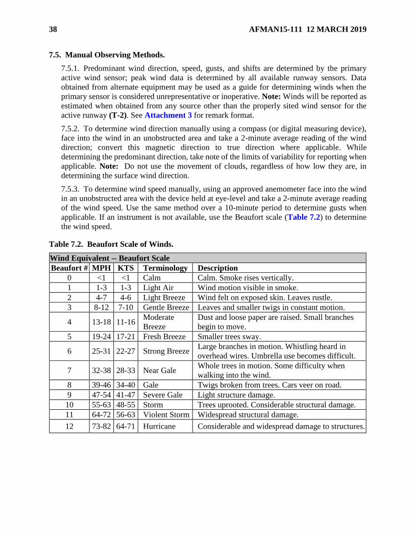
38 AFMAN15-111 12 MARCH 2019
7.5. Manual Observing Methods.
7.5.1. Predominant wind direction, speed, gusts, and shifts are determined by the primary
active wind sensor; peak wind data is determined by all available runway sensors. Data
obtained from alternate equipment may be used as a guide for determining winds when the
primary sensor is considered unrepresentative or inoperative. Note: Winds will be reported as
estimated when obtained from any source other than the properly sited wind sensor for the
active runway (T-2). See Attachment 3 for remark format.
7.5.2. To determine wind direction manually using a compass (or digital measuring device),
face into the wind in an unobstructed area and take a 2-minute average reading of the wind
direction; convert this magnetic direction to true direction where applicable. While
determining the predominant direction, take note of the limits of variability for reporting when
applicable. Note: Do not use the movement of clouds, regardless of how low they are, in
determining the surface wind direction.
7.5.3. To determine wind speed manually, using an approved anemometer face into the wind
in an unobstructed area with the device held at eye-level and take a 2-minute average reading
of the wind speed. Use the same method over a 10-minute period to determine gusts when
applicable. If an instrument is not available, use the Beaufort scale (Table 7.2) to determine
the wind speed.
Table 7.2. Beaufort Scale of Winds.
Wind Equivalent -- Beaufort Scale
Beaufort # MPH KTS Terminology Description
0 <1 <1 Calm Calm. Smoke rises vertically.
1 1-3 1-3 Light Air Wind motion visible in smoke.
2 4-7 4-6 Light Breeze Wind felt on exposed skin. Leaves rustle.
3 8-12 7-10 Gentle Breeze Leaves and smaller twigs in constant motion.
4 13-18 11-16 Moderate
Breeze
Dust and loose paper are raised. Small branches
begin to move.
5 19-24 17-21 Fresh Breeze Smaller trees sway.
6 25-31 22-27 Strong Breeze Large branches in motion. Whistling heard in
overhead wires. Umbrella use becomes difficult.
7 32-38 28-33 Near Gale Whole trees in motion. Some difficulty when
walking into the wind.
8 39-46 34-40 Gale Twigs broken from trees. Cars veer on road.
9 47-54 41-47 Severe Gale Light structure damage.
10 55-63 48-55 Storm Trees uprooted. Considerable structural damage.
11 64-72 56-63 Violent Storm Widespread structural damage.
12 73-82 64-71 Hurricane Considerable and widespread damage to structures.

AFMAN15-111 12 MARCH 2019 39
Chapter 8
VISIBILITY
8.1. Introduction. This chapter describes the observing and reporting standards for visibility.
Visibility is a measure of the opacity of the atmosphere and is expressed in terms of the horizontal
distance at which a person is able to see and identify specified objects. Visibility values are
reported in SM at U.S. locations (including Hawaii, Alaska and Guam); at overseas locations, the
unit of measure will be the same as that published for the installation in DoD FLIP airfield
approach plate minimums (i.e. usually meters). (T-2).
8.2. Visibility Group (VVVVVSM). The surface visibility, VVVVVSM (VVVV in meters for
overseas locations), is encoded using the values listed in Table 8.1 A space is encoded between
whole numbers and fractions of reportable visibility values. For example, a visibility of 1 1/ 2 SM
is encoded 1 1/2SM. The visibility group at US locations always ends in SM to indicate that
visibilities are in statute miles. Only FBWOS locations may use an M to indicate "less than" when
reporting visibility (e.g., M1/4SM (M0400) means a visibility less than 1/4 SM as reported by
AN/FMQ-19).
8.3. Visibility Algorithms. The visibility algorithm calculates the average visibility by
evaluating the sensor data gathered from a single point during a 10-minute period ending at the
actual time of the observation. Additionally, the data gathered during the averaging period is used
to determine if variable visibility should be reported. Where the FBWOS has meteorological
discontinuity sensors, the data from the additional sensors is examined to determine if their values
meet criteria for generating a visibility remark.
8.4. Standards and Reporting. The FBWOS sensors determine the average visibility over time
and record the corresponding reportable value as the prevailing visibility. If the visibility falls
halfway between two reportable values, the lower value is reported.
8.4.1. Prevailing visibility is determined by weather personnel as the greatest distance that can
be seen in at least half of the horizon circle and may not necessarily be continuous (i.e. may be
composed of sectors). Prevailing visibility represents a value determined from a height of
approximately 6 feet above the ground level and is reported using Table 8.1
8.4.2. Tower visibility is reported in column 13 when either the tower or prevailing visibility
is less than 4SM and they differ by at least one reportable value; see Attachment 3 for format.
Note: Tower visibility does not replace the prevailing visibility reported in the body of the
observation.
8.4.3. Variable prevailing visibility is reported in column 13 when the prevailing (or sensor
derived average) visibility is less than 3SM and rapidly fluctuating by at least 1/2SM during
the period of observation; see Attachment 3 for format.
8.4.4. Sector visibility is reported in column 13 when the visibility in at least 1/8th of the
horizon differs from the prevailing visibility by at least one reportable value and either the
prevailing or sector visibility is less than 3SM; see Attachment 3 for format.
8.4.5. Visibility at second location is reported in column 13 at locations equipped with two or
more visibility sensors when the visibility at the designated discontinuity sensor is lower than
the visibility in the body of the observation by a reportable value; see Attachment 3 for format.

40 AFMAN15-111 12 MARCH 2019
8.4.6. Software limitations in some automated sensors only support visibility reporting
increments of 1/4SM (from 0 to 1 3/4 SM) and 1/2 SM (from 2 to 3 SM). Leadership will
locally document procedures to ensure supplementation during controlled airfield hours for
observed values that are beyond the capability of the software to report when required to meet
published landing and/or circling minimum visibility values. (T-3).
Table 8.1. Visibility - Reportable Values.
Visibility - Reportable Values in SM | Meters
0 0000 1/2 0800 1 1/2 2400 3 4800
1/16 0100 5/8 1000 1 5/8 2600 4 6000
M1/8 M0200 3/4 1200 1 3/4 2800 5 8000
1/8 0200 7/8 1400 1 7/8 3000 6 9000
3/16 0300 1 1600 2 3200 7 9999
1/4 0400 1 1/8 1800 2 1/4 3600 8 9999
5/16 0500 1 1/4 2000 2 1/2 4000 9 9999
3/8 0600 1 3/8 2200 2 3/4 4400 10 9999
Notes:
1. Values are reported in 1SM increments from 10 to 15SM and 5SM increments above 15SM.
2. All values greater than 6SM are reported as “9999” when reporting in meters.
3. Some values may not be supported by FMQ-19, FMQ-23 or Automated Surface Obeserving
System (ASOS) software.
4. M1/8 (M0200) is an automated report for visibility less than 1/8SM (0200m).
5. MAJCOMs may direct the use of 3000m and 5000m in place of 3200m and 4800m
(OCONUS).
8.5. Manual Observing Methods.
8.5.1. Prevailing visibility is observed with un-aided vision (i.e. no binoculars or night vision
goggles) from a designated point of observation that permits the weather technician to evaluate
the horizon circle at the surface.
8.5.1.1. The point of observation should be as free from obstructions as possible to permit
the maximum view of the horizon circle. Where obstructions exist, move to as many
locations as necessary and practical within the period of observation to view as much of
the horizon as possible.
8.5.1.2. At locations that necessitate deviation, visibility may be determined from a
designated point of observation that is elevated but is always be reported as the surface
visibility and will be documented in the FLIP (e.g. “SFC VIS determined at ATC tower”
or “Visibility obs at 50ft AGL”). (T-2).
8.5.2. Evaluate visibility as frequently as practical using all available visibility markers to
determine the greatest distance that can be seen in all directions around the horizon circle.
8.5.2.1. If a marker has sharp outlines and little blurring of color, the visibility is much
greater than the distance to that marker.

AFMAN15-111 12 MARCH 2019 41
8.5.2.2. If a marker can be seen, the visibility is about the same as the distance to the
marker.
8.5.2.3. If a marker cannot be seen due to weather and/or reportable obscurations, the
visibility is less than the marker.
8.5.3. Under uniform conditions, consider the prevailing visibility to be the same as that
determined in any direction around the horizon circle.
8.5.4. Under non-uniform conditions, divide the horizon into sectors that have uniform
visibility and represent at least 1/8th of the horizon circle.
8.5.4.1. The greatest distance seen in least half of sectors that make up the horizon circle
(may be non-contiguous) is reported as the prevailing visibility.
8.5.4.2. The visibility in sectors is reported in remarks when they differ from the prevailing
visibility by one or more reportable value and either the prevailing or the sector visibility
is less than 3SM (4800 m) or if it is considered operationally significant; see examples in
Figure 8.1 and Attachment 3 for format.
8.5.5. If the visibility is rapidly fluctuating by at least 1/2SM (0800m) during the period of the
observation and the prevailing visibility is less than 3SM (4800 m), the visibility is considered
variable and the minimum and maximum visibility values observed are reported in remarks;
see Attachment 3 for format.
Figure 8.1. Determining Prevailing and Sector Visibility.

42 AFMAN15-111 12 MARCH 2019
8.5.6. In Figure 8.1, visibility of 5SM is the furthest that can be seen in sectors 3, 5, 6, 7, and
8. In sectors 1 and 2, visibility is reduced to 2SM due to an approaching fog bank. In sector 4,
a diminishing snow shower is still reducing visibility to 2 1/2SM. Based on this information,
prevailing visibility should be reported as 5SM and a sector visibility remark should be
reported with visibility of 2SM in the north through east (N-E) and 2 1/2SM to the south-
southeast (SSE).

AFMAN15-111 12 MARCH 2019 43
Chapter 9
RUNWAY VISUAL RANGE (RVR)
9.1. Introduction. This chapter describes the observing and reporting standards for RVR data.
RVR is an instrumentally derived value that represents the horizontal distance that a pilot can see
down the runway. The maximum distance in the direction of takeoff or landing at which the
runway, or specified lights or markers delineating it, can be seen from a position above a specified
point on its center. For all locations reporting RVR, the unit of measure will correspond to the
units of measure used to report visibility (i.e. feet for SM and m for meters). (T-2).
9.2. Runway Visual Range Group (RDRDR[DR]/VRVRVRVRFT). “FT” at the end of the group
indicates the units of measurement are in feet. Overseas locations will use measurement values as
published in the DoD Flight Information Publication (FLIP) (typically meters). Locations
reporting in meters will not include FT or any other indicator of units. (T-0).
9.2.1. RVR is encoded in the format RDRDR[DR]/VRVRVRVRFT, where R indicates the
runway number follows, DRDR[DR] is the runway number (the additional DR may be used for
runway approach directions, such as R for right, L for left, and C for center), VRVRVRVR is the
constant reportable value.
9.2.2. RVR that is varying is encoded in the format, RDRDR[DR]
/VNVNVNVNVVXVXVXVXFT, where VNVNVNVN is the lowest reportable value in feet, V
separates lowest and highest visual range values, VXVXVXVX is the highest reportable value.
The 10-minute RVR for runway 01L varying between 1,000 and 5,000 (0300 and 1500 m) feet
would be encoded "R01L/1000V5000FT" (R01L/0300V1500).
9.2.3. If the RVR is less than its lowest reportable value, the VRVRVRVR or VNVNVNVN groups
will be preceded by M. If the RVR is greater than its highest reportable value, the VRVRVRVR
or VXVXVXVX groups are preceded by a P. For example, an RVR of less than 100 feet (0050
m) will be encoded "M0100FT" (M0050); an RVR of greater than 6,000 feet (1500 m) will be
encoded "P6000FT" (P1500). (T-0).
9.3. RVR Algorithms. Most FBWOSs automatically sense and report RVR using a determined
10-minute average. Note: For OCONUS locations reporting RVR in meters, FBWOSs determine
RVR in 50-meter increments up to 800m and in 100-meter increments up to 1500m. This has a
minor effect on the RVR special requirements as derived from the reporting minima listed in the
FLIP (e.g. 0730 m is the published minima, the SPECI requirement will be set to 0750 m).
9.4. Standards and Reporting. RVR is reported using values in Table 9.1 whenever the
prevailing visibility is less than or equal to 1 SM (1600 m) and/or when RVR for the designated
instrument runway is less than or equal to 6000 ft (1500 m).
9.4.1. When an RVR reporting requirement is occurring but the 10-minute average cannot be
determined, no value will be reported and RVRNO will be included in column 13 remarks. (T-
1).
9.4.2. At automated stations where it is applicable, RVR values for as many as four designated
runways can be reported for long-line dissemination. At manual stations, only RVR for the
designated runway is reported. See Table 9.2 for RVR observing and reporting standards.

44 AFMAN15-111 12 MARCH 2019
9.4.3. RVR Information Not Available (RVRNO remark). Indicates the 10-minute average
touchdown RVR for the in-use runway is not available (e.g., equipment failure) during periods
when prevailing visibility is 1 mile (1600 m) or less or RVR is 6,000 feet (1830 m) or less.
RVRNO is not reported in the body of the METAR/SPECI and will be reported in the remarks
IAW Attachment 3. (T-0).
Table 9.1. RVR Reportable Values.
RVR - Reportable Values in Feet | Meters
Feet Meters Feet Meters Feet Meters Feet Meters
M0100 0900 0650 3500
0100 M0050 1000 0300 2200 4000 1200
0200 0050 1200 0350 0700 1300
0300 0100 0400 2400 0750 4500
0400 1400 2600 0800 1400
0500 0150 0450 2800 5000 1500
0600 1600 0500 3000 0900 5500 P1500
0700 0200 1800 0550 1000 6000
0800 0250 2000 0600 1100 P6000
Note:
1. Values preceeded with an “M” indicate less than; a “P” indicates greater than.
Table 9.2. Summary of RVR Observing and Reporting Standards.
9.5. Manual Observing Methods. RVR is an instrument derived measurement, there is not a
manual observing method to determine RVR values.

AFMAN15-111 12 MARCH 2019 45
Chapter 10
PRESENT WEATHER
10.1. Introduction. This chapter describes present weather and reporting standards including
qualifiers and weather phenomena. Reports may be instrument derived, physically observed or
determined using a combination of the two. Unless otherwise noted, the term “on station” refers
to phenomena detected/determined to be occurring within 5NM of the point of observation.
10.2. Present Weather Group (w'w'). The following general rules apply when reporting
present weather in a METAR or SPECI report:
10.2.1. Weather occurring within 5 SM (unless directed elsewhere in nautical miles for
thunderstorms and lightning) of the point of observation is encoded in the body of the report.
Weather occurring in the vicinity of the station (between 5 and 10 SM unless directed
elsewhere in nautical miles for thunderstorms and lightning) is also encoded in the body of the
report. FBWOSs only use the vicinity (VC) qualifier with thunderstorms (TS). Augmented
stations may report weather not occurring at or in the vicinity of the station in the remarks.

46 AFMAN15-111 12 MARCH 2019
Table 10.1. Notations for Manually Reporting Present Weather.
QUALIFIER WEATHER PHENOMENA
INTENSITY
OR
PROXIMITY
1
DESCRIPTO
R
2
PRECIPITATIO
N
3
OBSCURATIO
N
4
OTHER
5
- Light
Moderate
+ Heavy
VC VC - In the
Vicinity
MI shallow
PR Partial
BC Patches
DR Low
Drifting
BL Blowing
SH Shower(s)
TS Thunderstorm
FZ Freezing
DZ Drizzle
RA Rain
SN Snow
SG Snow Grains
IC Ice Crystals
PL Ice Pellets
GR Hail
GS Snow Pellets
BR Mist
FG Fog
FU Smoke
VA Volcanic
Ash
DU Widespread
Dust
SA Sand
HZ Haze
PY Spray
PO Well-
Developed
Dust/Sand
Whirls
SQ Squalls
FC4
FC Funnel
Cloud(s)
(including a
Tornado, or
Waterspout)
SS Sandstorm
DS Dust
Storm
Note: For airfields operating an ASOS, the shaded elements in this table indicate
qualifier/phenomena or combinations that are not possible and will not be reported due to
restrictions in the current software configuration. (T-0). Manual or augmented observations
created on an ASOS will contain these elements if permitted by a future software upgrade. (T-
0).
10.2.2. Separate groups are used for each type of present weather. Each group is separated
from the other by a space. A METAR/SPECI will contain no more than three present weather
groups. The groups will be ordered by priority based on Table 10.2 (T-0).

AFMAN15-111 12 MARCH 2019 47
Table 10.2. Present Weather Reporting Order.
10.3. Present Weather Qualifiers. Present weather groups are constructed by considering
columns 1 through 5 in Table 10.1 in sequence (e.g., heavy freezing rain is encoded +FZRA).
10.3.1. Intensity Qualifier (- , +). The intensity qualifier will be used to encode light (-),
moderate (no symbol), and heavy (+) intensities with all reportable precipitation types, to
include precipitation appended to showers, thunderstorms, and freezing precipitation. (T-1).
Ice crystals (IC), unknown precipitation (UP) and hail (GR), including those associated with a
TS and showers (SH), will not use intensity qualifiers. No intensity will be ascribed to the
obscurations of blowing dust (BLDU), blowing sand (BLSA), blowing snow (BLSN), blowing
spray (BLPY), well-developed dust/sand whirls (PO) and squalls (SQ). Tornados and
waterspouts are encoded as +FC, while a funnel cloud is always encoded as FC. Only moderate
or heavy intensity are ascribed to sandstorm (SS) and dust storm (DS). (T-0).
10.3.2. Proximity Qualifier. VC (weather phenomena observed in the vicinity of, but not at
the point of observation), will only be encoded in combination with FG, SH, PO, BLDU,
BLSA, BLSN, SS, DS and TS. Intensity qualifiers will not be encoded with VC. VCFG will
be encoded to report any type of fog in the vicinity of the point(s) of observation. Precipitation
not occurring at the point of observation but within 10SM will be encoded as showers in the
vicinity (VCSH). (T-0).
10.3.3. Descriptor Qualifier. Only one descriptor will be encoded for each weather phenomena
group (e.g., -FZDZ). Mist (BR), Haze (HZ), Smoke (FU), and Volcanic Ash (VA) will not be
encoded with any descriptor. (T-0).
10.3.3.1. The descriptors shallow (MI), partial (PR), and patches (BC) are only encoded
with FG (e.g., MIFG). For MIFG (shallow fog) to be encoded, FG must cover part of the
station, extend no higher than 6 feet above the ground, with visibility more than 6 feet
above the ground 5/8SM (1000 m) or more, while the apparent visibility in the FG layer is
less than 5/8SM (1000 m). For PRFG (partial fog) to be encoded, FG must cover a
substantial part of the station and extend to at least 6 feet above the ground with visibility
in the FG less than 5/8SM (1000 m). For BCFG (fog patches) to be encoded, FG must
randomly cover part of the station and extend to at least 6 feet above the ground with the
apparent visibility in the FG patch or bank less than 5/8SM (1000 m), while visibility over
other parts of the station is greater than or equal to 5/8SM (1000 m).

48 AFMAN15-111 12 MARCH 2019
10.3.3.2. The descriptors low drifting (DR) and blowing (BL) are only encoded with dust
(DU), sand (SA), and snow (SN) (e.g., BLSN or DRSN). DR will be encoded for DU, SA,
or SN raised by the wind to less than 6 feet above the ground. (T-0). When BLSN is
observed with SN falling from clouds, both phenomena are reported (e.g., SN BLSN).
When, because of BLSN, the weather technician cannot determine whether or not SN is
also falling, then only "BLSN" will be reported. (T-0). BL may also be encoded with spray
(PY).
10.3.3.3. SH is encoded only with one or more of the precipitation types of rain (RA), SN,
PL, GS or GR. The SH descriptor indicates showery-type precipitation. When showery-
type precipitation is encoded with VC (VCSH), the intensity and type of precipitation is
not encoded.
10.3.3.4. The descriptor TS may be encoded by itself, i.e., a TS without associated
precipitation, or it may be encoded with precipitation. If encoding a TS with precipitation,
the following are the authorized types: RA, SN, PL, GS, GR, UP. For example, a TS with
SN and GS would be encoded as "TSSNGS."
10.3.3.5. The descriptor freezing (FZ) is only encoded in combination with FG, drizzle
(DZ) or RA (e.g., FZRA, FZFG, FZDZ). FZ is only reported with FG when the temperature
is less than 0 degrees Celsius.
10.3.4. Precipitation. FBWOSs may have one type of precipitation per observation and
augmented stations may have up to three types of precipitation encoded in a single present
weather group. They are encoded in decreasing predominance based on intensity. Only one
intensity indicator (+ or -) may be encoded and it refers to the intensity of the total precipitation.
10.3.4.1. Precipitation types are DZ, RA, SN, IC, PL, GS, GR and SG. Report the start
and end of all precipitation types.
10.3.4.2. GR is reported regardless of the size of the hail stone. Measure the largest stone
and report the size in ¼ inch increments in the Remarks. If no hail size is reported, it will
be assumed to be small hail. (T-0).
10.3.5. Obscurations. With the exception of VA, DRDU, DRSA, DRSN, MIFG, PRFG, and
BCFG, obscurations are encoded in the body of the report if the surface visibility is less than
7SM (9999 m). Reportable obscurations are FG, BR, FU, VA, DU, SA, HZ, and PY.
10.3.5.1. BR is reported when the obscuration consists of water droplets or ice crystals and
the visibility is at least 5/8 SM (1000 m), but less than 7SM (9999 m).
10.3.5.2. FG is reported when the obscuration consists of water droplets or ice crystals
(FG or FZFG) and the visibility is less than 5/8SM (1000 m). FZ is only reported with FG
when visibility is less than 5/8 SM (1000 m) and temperature is less than 0 degrees Celsius.
10.3.5.3. VA is always reported when present.
10.3.5.4. PY is encoded only when used with the descriptor BL.
10.3.6. Other Weather Phenomena.
10.3.6.1. SQ is reported when a sudden increase in wind speed of at least 16 knots is
observed, and is sustained at 22 knots or more for at least 1 minute.

AFMAN15-111 12 MARCH 2019 49
10.3.6.2. Sandstorms are encoded as SS, dust storms as DS. Report a moderate SS/DS
when visibility is reduced to less than 5/8 statute mile (1000 m) and greater than or equal
to 5/16 statute mile (0500 m) due to BLSA/BLDU. Report a +SS/+DS if visibility is less
than 5/16 statute mile (0500 m) due to BLSA/BLDU.
10.3.6.3. Well-developed sand or dust whirls are encoded as PO.
10.4. Present Weather Capabilities of an FBWOS. Using multiple sensors in conjunction,
FBWOSs can determine and report the proximity, type and intensity of precipitation as well as
obscurations and report up to three precipitation/obscuration groups.
10.4.1. For liquid precipitation, the FBWOS determines intensity from particle size and fall
velocity through the sensor field. For snowfall, the minimum intensity is based on the reported
surface visibilities and may be reported higher than what is occurring due to other phenomena
that are reducing visibility.
10.4.2. When equipped with a working lightning detection capability, an FBWOS reports
thunderstorms as on station when cloud-to-ground lightning is detected within 5NM, in the
vicinity when detected between 5 and 10NM, and as a lighting distant remark in column 13
when detected between 10 and 30NM. See Table 10.3 for a list of the qualifiers, weather, and
obscurations reported by an FBWOS. Note: In addition to Table 10.3, the FMQ-23 can also
detect Hail (GR) and Ice Pellets (PL).
Table 10.3. Automated Present Weather Reporting.
10.5. Standards and Reporting. Unless specifically noted below, present weather will only be
reported in the body of the observation when it is determined to be occurring on station or in the
vicinity at the time of observation. (T-1). Other significant weather phenomena not on station
should be reported in the remarks section when it is determined to be operationally significant.
10.5.1. Up to three groups will be reported when augmenting or encoding manual
observations. Each group will have up to one intensity/proximity qualifier and/or descriptor
and up to three types of weather phenomena. (T-1).

50 AFMAN15-111 12 MARCH 2019
10.5.2. When multiple phenomena are appended to an intensity qualifier, the qualifier is
denoting the intensity of the total precipitation.
10.5.3. Present weather groups will be encoded in the following order and precedence: (T-1).
10.5.3.1. Tornadic Activity - Tornado, Funnel Cloud, then Waterspout.
10.5.3.2. Thunderstorms - on station or in the vicinity, with or without associated
precipitation.
10.5.3.3. Precipitation in order of decreasing predominance.
10.5.3.4. Obscurations and/or other phenomena in order of decreasing predominance.
10.6. Descriptors. Descriptors serve to further describe certain weather phenomena to provide
additional specificity on the observed conditions. Additional information for each descriptor (with
encoded form in parenthesis) is provided below and in Table 10.1
10.6.1. Shallow (MI): Only used to describe fog that has very little vertical extent (<6ft) where
visibility is reduced in the horizontal but can be easily seen through when looking in the
vertical.
10.6.2. Partial (PR): Only used to describe fog where visibility is reduced in the horizontal
and covers part of the celestial dome but does not constitute a vertical visibility sky condition
(i.e. a surface-based obscuration covering less than 8 oktas of the sky).
10.6.3. Patches (BC): Only used to describe small areas of fog with little vertical extent (~6-
20ft).
10.6.4. Low Drifting (DR): Only used to describe dust, sand, or snow that is being raised by
the wind to a height of less than 6ft and is not obstructing visibility.
10.6.5. Blowing (BL): Only used to describe dust, sand, snow, or spray that is being raised by
the wind to a height above 6ft and is obstructing visibility.
10.6.6. Shower(s) (SH): Only used to describe showery-type (cumuliform) precipitation;
characterized by a rapid start, stop, and/or change in intensity. When encoded as in the vicinity,
the type of precipitation is not included (i.e., VCSH not VCSHRA).
10.6.7. Thunderstorm (TS): May be encoded by itself or with an associated precipitation
type(s); RA, SN, PL, GS, GR, and UP are the authorized types of precipitation that may be
appended to TS. When it is determined that a thunderstorm is within 5-10NM, it may be
encoded as VCTS. If thunder is heard and the distance cannot be reliably determined, TS will
be encoded as on station. (T-2). See manual observing procedures for additional guidance on
determining the use of TS in the body of the observation.
10.6.8. Freezing (FZ): Only encoded with fog when the temperature is below freezing or with
rain or drizzle when super-cooled liquid droplets are freezing on contact with surface objects
and coating them with a glaze of ice.
10.7. Weather Phenomena. Weather phenomena are divided into the three categories of
precipitation, obscurations, and other.
AFMAN15-111 12 MARCH 2019 51
10.7.1. Precipitation is any form of water particle, whether in a liquid, freezing or frozen state,
that falls from the atmosphere and reaches the ground. Precipitation may be encoded in the
body of the observation with or without a reduction in prevailing visibility.
10.7.1.1. Drizzle (DZ): A form of liquid precipitation characterized by fairly uniform
drops with diameters of less than 0.02-inch (0.5 mm) that are very close together. Drizzle
appears to float while following air currents but unlike fog droplets, it does fall to the
ground. May be encoded with the qualifiers light, moderate, heavy and/or freezing.
10.7.1.2. Rain (RA): A form of liquid precipitation that can be showery or uniform and is
characterized by droplets that are generally larger than 0.02-inch (0.5 mm). Smaller
droplets may occur from stratiform clouds but unlike drizzle, the droplets are widely
separated. May be encoded with the qualifiers light, moderate, heavy, showers,
thunderstorms and/or freezing. Precipitation not occurring at the point of observation but
within 10 statute miles is coded as showers in the vicinity (VCSH).
10.7.1.3. Snow (SN): A form of solid precipitation composed of white or translucent ice
crystals, most of which are complex branch hexagonal forms and often combined into
flakes. May be encoded with the qualifiers light, moderate, heavy, showers, and/or
thunderstorms. Additionally, snow can be qualified as drifting, blowing and in the vicinity
if blowing (VCBLSN).
10.7.1.4. Snow Grains (SG): A form of solid precipitation made up of very small, white,
opaque particles of ice; the frozen equivalent of drizzle. When the grains hit hard ground
they do not bounce or shatter and usually fall in small quantities, mostly from stratus type
clouds and never as showers. May be encoded with the qualifiers light, moderate, and/or
heavy.
10.7.1.5. Ice Crystals (IC): A form of solid precipitation that falls as unbranched ice
crystals in the form of needles, columns or plates. Under certain conditions, can appear
without precipitable overhead cloud cover and is commonly referred to as Diamond Dust.
Is not encoded with any qualifiers when it is the sole form of precipitation in the weather
group.
10.7.1.6. Ice Pellets (PL): Hard grains of ice consisting of frozen raindrops, or largely
melted and refrozen snowflakes. Ice pellets are transparent or translucent pellets of ice,
which are round or irregular, rarely conical, and which have a diameter of 0.2 inch (5 mm),
or less.
10.7.1.7. Hail (GR): Precipitation in the form of small balls or other pieces of ice falling
separately or frozen together in irregular lumps. Hail includes small hail, which is pellets
of snow encased in a thin layer of ice which have formed from the freezing, either of
droplets intercepted by the pellets, or of water resulting from the partial melting of the
pellets.
10.7.1.8. Snow Pellets (GS): A form of solid precipitation composed of white, opaque
grains of ice. GS is normally round or conical, brittle, easily crushed, and rebound when
falling on hard surfaces. Diameters range from 0.08 to 0.2 inch (2 to 5 mm).

52 AFMAN15-111 12 MARCH 2019
10.7.1.9. Unknown Precipitation (UP): A form of precipitation reported by an FBWOS
when it detects precipitation is occurring but cannot determine the type. UP is not reported
in manual or augmented observations.
10.7.2. Obscurations are a collection of particles (hydrometeors and lithometeors) in contact
with the surface or aloft and reported in the body of the observation when they are in a dense
enough concentration to be reducing visibility below 7SM.
10.7.2.1. Mist (BR): A form of obscuration composed of minute water particles or ice
crystals suspended in the atmosphere. BR is reported when visibility is greater than or equal
to 5/8SM (1000m) but less than 7SM (9999m). Mist can be distinguished from haze by
color and moisture content; when viewed against the background, mist produces a grayish
tinge.
10.7.2.2. Fog (FG): A form of obscuration composed of minute water particles suspended
in the atmosphere. FG is a denser concentration than BR and is reported when visibility is
reduced to less than 5/8SM (1000m). When the temperature is less than 0oC and FG is
present, report as FZFG, even if ice is not accumulating on exposed surfaces. FG may also
be encoded with the descriptors VC, MI, PR, and BC.
10.7.2.3. Smoke (FU): Small particles produced by combustion that are suspended in the
air. When present may cause the sun to appear very red at sunrise and sunset and during
the daytime, can cause a reddish tinge to the background. Smoke that has traveled a great
distance from its source usually has a light grayish or bluish color and is evenly distributed
in the air.
10.7.2.4. Volcanic Ash (VA): Fine particles of rock powder that have erupted from a
volcano and remain suspended in the atmosphere for long periods of time. Volcanic Ash
will always be reported in the body of the observation when observed, regardless of the
visibility and vicinity to the station. (T-1).
10.7.2.5. Widespread Dust (DU): Solid materials suspended in the atmosphere in the form
of small irregular particles, many of which are microscopic in size. When lifted to high
enough levels in the atmosphere, dust may travel and be observed as it settles at locations
significantly far from the original source region.
10.7.2.6. Sand (SA): Sand particles picked up from the surface of the earth by the wind,
reducing the horizontal visibility.
10.7.2.7. Haze (HZ): Extremely small, dry particles suspended in the air in sufficient
enough numbers to reduce visibility. May be distinguished from mist by color and moisture
content; when viewed against a dark background, produces a bluish tinge and when viewed
against a light background, appears as a yellowish veil.
10.7.2.8. Spray (PY): Water droplets displaced by the wind from a body of water,
generally from the crests of waves, and carried up into the air in such quantities that they
reduce the horizontal visibility. When observed to be reducing visibility, spray is always
reported as blowing (BLPY).

AFMAN15-111 12 MARCH 2019 53
10.7.3. Other Phenomena are meteorological events that do not necessarily directly reduce
visibility but are of enough significance that they warrant reporting in an observation when
they are in the area (i.e. on-station, in the vicinity, or distant). When applicable, additional
information describing the nature of the phenomena is included in column 13 remarks
following the guidance in Attachment 3.
10.7.3.1. Well-Developed Dust/Sand Whirl (PO): Dust or sand that is raised from the
ground and takes the form of a whirling column with varying height, small diameter and
an approximate vertical axis. Commonly referred to as “Dust Devils,” they typically form
in dry regions on hot, calm days when intense surface heating causes a very steep
temperature lapse rate in the lower levels of the atmosphere; may be strong enough to cause
wind damage.
10.7.3.2. Squall (SQ): A strong wind event characterized by a sudden increase in speed of
at least 16 kts with sustained speeds of at least 22 kts for at least 1 minute.
10.7.3.3. Funnel Cloud (FC): A funnel shaped mass of moisture and/or debris associated
with a violent, rotating column of air. Funnel clouds usually form as pendants from
cumulonimbus clouds and may be observed over land or water but do not touch the surface.
Can be confused with scud/inflow bands which appear similar in appearance but do not
rotate.
10.7.3.4. Tornado/Water Spout (+FC): A funnel shaped mass of moisture and/or debris
associated with a violent, rotating column of air that does touch the surface. Regardless of
where they form or move, this phenomenon is reported as a Tornado while over land and
a Water Spout while over water; both are encoded as +FC.
10.7.3.5. Dust storm (DS): An unusual, frequently severe weather condition characterized
by strong winds and dust-filled air that can reduce visibility over an extensive area, often
preceded by a wind driven dust wall that can exceed 3,000ft in vertical extent.
10.7.3.6. Sandstorm (SS): A wind driven event, typically occurring during the heat of the
day and dying out at night, where particles of sand are lifted enough to cause a reduction
in visibility. Unlike a DS, the sand is mostly confined to the lowest 10ft and rarely rises
more than 50ft above the ground.
10.8. Manual Observing
10.8.1. Present weather is determined through physical observation and by using a
combination of the Qualifiers, Precipitation Types, Obscurations, and Other Phenomena
described above. These elements, combined with prevailing and sector visibility, dictate what
present weather is encoded.
10.8.2. When observed to be occurring on station, all forms of precipitation will be reported.
(T-1). Use Table 10.4 to determine precipitation intensity (applicable intensity qualifier) based
on rate-of-fall, accumulation characteristics, and/or visibility. If in the vicinity, should be
reported using the VC qualifier; in this case, no intensity is assigned. If precipitation is
observed to be occurring beyond 10SM of the observation point, may be reported in column
13 remarks as distant.

54 AFMAN15-111 12 MARCH 2019
Table 10.4. Determining Precipitation Intensity.
Rain / Ice Pellets - Based on Rate-of-Fall (See Notes 1)
Intensity Criteria
Light Rate of up to 0.10” per hr; maximum 0.01 inch in 6 minutes
Moderate Rate of 0.11” - 0.30” per hr; more than 0.01 inch to 0.03 inch in 6
minutes
Heavy Rate of more than 0.30” per hr; more than 0.03 inch in 6 minutes
Rain - Based on accumulation
Intensity Criteria
Light
Scattered drops that, regardless of duration, do not completely wet an
exposed surface up to a condition where individual drops are easily
seen.
Moderate Individual drops are not clearly identifiable; spray is observable just
above pavements and other hard surfaces
Heavy Rain seemingly falls in sheets; individual drops are not identifiable;
heavy spray to height of several inches is observed over hard surfaces
Ice Pellets - Based on Accumulation and Visibility
Intensity Criteria
Light Scattered pellets that do not completely cover an exposed surface
regardless of duration; visibility is not affected
Moderate Slow accumulation on ground; visibility reduced by ice pellets to less
than 7SM (9999m)
Heavy Rapid accumulation on ground; visibility reduced by ice pellets to less
than 3SM (4800m)
Snow / Snow Pellets / Drizzle - Based on visibility
Intensity Criteria
Light Visibility > 1/2SM (800m)
Moderate Visibility > 1/4SM (0400m) but ≤ 1/2SM (800m)
Heavy Visibility ≤ 1/4SM (0400m)
Notes:
1. Intensity is determined based on the rate
10.8.3. Hail (GR). When observed on station, regardless of size, hail will be encoded GR as
present weather in column 5. All reports of hail must include the size of the largest hailstone
observed in the Remarks (RMK) section of METAR/SPECI in increments of 1/4 inch. If no
hail size is reported, it will be assumed to be small hail. If the initial observation to report the
beginning or ending of hail is missed (e.g. personnel sheltering for safety), at the first
opportunity, disseminate a full observation including the begin/end times of the hail activity
following the format in Attachment 3. (T-1).

AFMAN15-111 12 MARCH 2019 55
10.8.4. When observed to be occurring, thunderstorms and any associated precipitation will
be reported as on station, in the vicinity, or as distant using the following guidelines and Figure
10.1 (T-1). If known, the distance, direction and direction of movement for storms within
30NM of the location will be included in column 13 remarks following guidance in
Attachment 3.
10.8.4.1. A thunderstorm is considered to be observed through detected/observed lighting,
audible thunder, or the presence of hail (GR) if the local noise level is such that thunder
cannot be heard. (T-0).
10.8.4.2. If a thunderstorm is positively identified as being within 5NM of the point of
observation or a thunderstorm is observed and the location cannot be positively identified,
thunderstorms will be reported as occurring on station. (T-0). Positive identification is
achieved through lighting detection equipment and/or display and interpretation of
available radar imagery (i.e. 40dBz elevated to -10oC height within storm core). Visual
positive identification will only be used when lighting is seen to strike an object at a known
distance. Note: Estimating the distance of a lightning strike based on bolt/flash intensity or
the “flash-bang” method is not a suitable means of determining distance.
10.8.4.3. When lightning is observed at a manual station, the frequency, type of lightning,
and location shall be reported. The remark shall be coded in the format listed in
Attachment 3. The contractions for the type and frequency of lightning shall be based on
Table 10.5 (T-0).
Table 10.5. Type and Frequency of Lightning.
10.8.4.4. If a thunderstorm can be positively identified as being located within 5-10NM of
the point of observation, thunderstorms will be encoded as in the vicinity. (T-0).
10.8.4.5. If a thunderstorm is positively identified as beyond 10NM of the point of
observation, thunderstorms are not encoded in the body of the observation as present
weather; in this case, only a column 13 remark is appropriate.
10.8.4.6. Through the lifecycle of a thunderstorm, it may move through any combination
of on-station, in the vicinity, and/or distant and be reported as such.

56 AFMAN15-111 12 MARCH 2019
10.8.4.7. A thunderstorm is considered to have ended when 15 minutes has elapsed since
the occurrence of the criteria in paragraph 10.8.4.2. (T-0).
10.8.4.8. If the initial observation to report the beginning or ending of tornadic activity,
hail, or thunderstorm activity is missed (e.g. personnel sheltering for safety), at the first
opportunity, follow the procedures for delayed reporting. Then disseminate a full
observation including the begin/end times of the thunderstorm following the format in
Attachment 3. (T-1).
Figure 10.1. Thunderstorm Determination.
10.8.5. When observed, determine the requirement to report obscurations in conjunction with
the following criteria:
10.8.5.1. When obscurations are reducing the prevailing visibility below 7SM (9999) they
will be encoded in column 5 as a present weather obscuration. (T-1).
10.8.5.2. When obscurations are observed but are not reducing visibility they should be
reported in the remarks section when it is determined to be operationally significant but are
not encoded in column 5. Exception: volcanic ash will always be reported in the body of
the observation when observed, regardless of the visibility and vicinity to the station. (T-
1).
10.8.6. When observed, determine the requirement to report other weather phenomena in
conjunction with the following criteria:
10.8.6.1. Tornadic activity will always be reported in the body of the observation when
observed. (T-1).
10.8.6.2. Funnel clouds, water spouts, and tornadoes will be reported in observations when
first observed, if they transition from one type to another (i.e. FC becomes +FC), and when
they end. (T-1).

AFMAN15-111 12 MARCH 2019 57
10.8.6.2.1. When first observed, follow the format in Attachment 3 to immediately
encode and disseminate an observation including all elements from the body of the
observation and the single remark for tornadic activity.
10.8.6.2.2. If the initial observation to report the beginning, change in type, or ending
of tornadic activity is missed (e.g. personnel sheltering for safety), at the first
opportunity follow the format in Attachment 3 to disseminate a full observation
including the begin/end times of the tornadic activity. (T-1).

58 AFMAN15-111 12 MARCH 2019
Chapter 11
SKY CONDITION
11.1. Introduction. This chapter describes the observing and reporting standards for sky
condition. Sky condition is a description of the celestial dome as seen from a single point on the
surface of the earth and is reported with relation to what could be seen if there was an unobstructed
view from horizon to horizon.
11.2. Sky Condition Group (NsNsNshshshs or VVhshshs or SKC or CLR). Sky condition is
encoded in the format, NsNsNshshshs, where NsNsNs is the amount of sky cover and hshshs is the
height of the base of the layer in hundreds of feet above the surface. There is no space between the
amount of sky cover and the height of the layer. Report layer height using reportable values in
Table 11.1
11.2.1. Sky condition is encoded in ascending order up to the first overcast layer. At mountain
locations, if the cloud layer is below the observation location elevation, the height of the layer
will be reported in the body of the METAR or SPECI as "///." (T-0).
11.2.2. No more than six layers will be reported. If more than six layers are observed during
back-up, weather technicians will use Table 11.2 to help determine which layers are to be
reported. (T-0).
Table 11.1. Increments of Reportable Values of Sky Cover Height.
Range of Height Values (feet) Reportable Increment (feet)
≤5,000 To nearest 100
> 5,000 but ≤10,000 To nearest 500
> 10,000 To nearest 1,000
Table 11.2. Priority for Reporting Layers.
Priority Layer Description
1 Lowest few layer
2 Lowest broken layer
3 Overcast layer
4 Lowest scattered layer
5 Second lowest scattered layer
6 Second lowest broken layer
7 Highest broken layer
8 Highest scattered layer
11.2.3. Vertical visibility is encoded in the format, VVhshshs, where VV identifies an
indefinite ceiling and hshshs is the vertical visibility into the indefinite ceiling in hundreds of
feet. There is no space between the group identifier and the vertical visibility.
11.2.4. Clear skies are encoded in the format, CLR or SKC, where CLR is the abbreviation
used by all FBWOS locations and SKC is used by manual stations to indicate no clouds are
present.

AFMAN15-111 12 MARCH 2019 59
11.2.5. Each layer is separated from other layers by a space. The sky cover for each layer
reported is encoded by using the appropriate reportable contraction. The report of clear skies
(CLR or SKC) is reported by itself. The abbreviations FEW, SCT, BKN and OVC will be
followed, without a space, by the height of the cloud layer. (T-0).
11.2.6. A partial obscuration will be encoded with the reportable layer construction
corresponding to the amount of the sky that is obscured followed by the layer height. A surface-
based obscuration will have a layer height of 000. A remark will also be appended for any
surface-based obscurations. For example: fog obscuring 2/8ths of the sky would be encoded
in the body of the report as FEW000 and clarified in the remarks as FG FEW000. (T-0).
11.3. Sky Condition Algorithms. An FBWOS derives sky condition by detecting the frequency
and height of clouds that move over the sensor over a continuously averaged period of 30 minutes.
The data collected from the sensor is processed into coverage amount, height and variability of
clouds.
11.3.1. FBWOS sensors are capable of reproducing a sky condition report comparative to that
of a human weather technician but may perform poorly in situations where clouds develop in
the vertical but have little horizontal movement (i.e. convective clouds either remain directly
over sensor and are over-reported or do not pass over the sensor and are under-reported). When
equipped with multiple ceilometers, the data from the discontinuity sensors are examined and
compared with the primary sensor to determine the requirement to report non-uniform ceiling
conditions IAW Attachment 3.
11.3.2. FBWOSs report sky condition from 100ft up to a maximum of 25,000ft. Note: Some
systems may report heights exceeding 25,000ft.
11.4. Standards and Reporting. Sky condition is an evaluation of all obscurations/clouds
making up layers at different heights and is reported in oktas (eighths) using a code form with
appended height above the surface. Sky condition is reported in all METAR and SPECI
observations.
11.4.1. Clouds and/or obscuring phenomena (not necessarily all of the same type) with bases
at approximately the same level constitute a layer. They may be either continuous or composed
of detached elements. A trace aloft is evaluated as 1/8th; however, a surface-based obscuring
phenomenon is only classified as a layer when it covers at least 1/8th of the sky. All layers are
treated as opaque.
11.4.2. Heights of layers are reported using a three-digit value representing hundreds of feet
above the surface and are rounded to a reportable increment. Layer heights up to 5,000ft are
reported to the nearest 100 feet, layer heights between 5,000ft and 10,000ft are reported to the
nearest 500ft and layers above 10,000ft are reported to the nearest 1,000ft. When a value falls
halfway between two reportable increments, the lower value is reported.
11.4.3. Sky cover is determined using the summation principle. This principle states that the
sky cover at any level is equal to the sky cover in all lower levels up to and including the layer
in question. In other words, no layer can be classified as less than the layers below it and no
total sky cover can be greater than 8/8ths. See Figure 11.1 for an example of the summation
principle.

60 AFMAN15-111 12 MARCH 2019
11.4.4. Sky cover code forms reflect the degree of sky coverage based on a summation of the
amount of clouds/obscuring phenomena at and below layer being evaluated. The approved
code forms are listed below (with encoded form in parenthesis):
11.4.4.1. Sky Clear (SKC or CLR) - The absence of any clouds/obscuring phenomena;
0/8ths coverage. Note: Sometimes encoded as NCD or NSC by automated stations and
organizations outside of AF weather to indicate No (Significant) Clouds Detected below
12,000ft (or 25,000ft with the 25K algorithm); CLR, NCD and NSC do not necessarily
indicate clear skies.
11.4.4.2. Few (FEW) - A trace through 2/8ths coverage.
11.4.4.3. Scattered (SCT) - 3/8ths through 4/8ths coverage.
11.4.4.4. Broken (BKN) - 5/8ths through less than 8/8ths. Note: The lowest BKN or
greater layer represents the ceiling.
11.4.4.5. Overcast (OVC) - The sky is completely covered by clouds/obscuring
phenomena; 8/8ths coverage. Note: All layers are treated as opaque (i.e. an overcast layer
of thin cirrus can be seen through however the sky is still overcast).
11.4.4.6. Vertical Visibility (VV) - The sky is completely covered by a surface-based
phenomena (e.g. snow, fog); 8/8ths coverage. The terms totally obscured and indefinite
ceiling may also be used in relation to this sky condition. Note: Vertical Visibility
constitutes a ceiling.
11.4.5. For aviation purposes, the reported ceiling is defined as the lowest height at which the
summation of layers equals broken or greater coverage (> 5/8ths) or the maximum height that
can be observed into a vertical visibly obscuration.
11.4.6. A variable ceiling represents a situation in which the height of the ceiling rapidly
increases and decreases by specified amounts during the period of observation and the ceiling
is below 3,000ft. See Table 11.3 for additional reporting criteria.
Table 11.3. Criteria for Variable Ceiling.
Ceiling (feet) Variation Amount (feet)
< 1,000 200
> 1,000 and 2,000 400
> 2,000 and < 3,000 500
11.4.7. A variable sky condition represents a situation in which a layer varies rapidly in
coverage amount by at least one reportable value during the period of the observation and the
layer is below 3,000ft.
11.4.8. Sky cover and ceiling heights from PIREPS should be used to maintain situational
awareness and to compare against the determined or sensor derived sky condition. Convert
cloud bases reported in PIREPs from mean sea level (MSL) to above ground level (AGL)
before comparing to the local data. Reevaluate sky cover and ceiling heights when PIREPS
indicate an operationally significant difference from the current observation.

AFMAN15-111 12 MARCH 2019 61
11.5. Manual Observing Methods. The legacy Qualification Training Package Observing –
Trainer’s Guide, found on the AFWKC and the WMO-No. 407 International Cloud Atlas, Volume
II both contain references and photographs for identifying the various cloud forms and can be used
as a resource when determining significant cloud types and amounts. Sky condition will be
evaluated in all METAR and SPECI observations. (T-1).
11.5.1. All layers visible from the point of observation are considered in sky cover reports. A
maximum of six layers may be reported. When more than six layers are present, use Table
11.2 to determine reporting priority.
11.5.2. When observed, significant cloud types will be reported in the observation using the
following guidance. (T-1).
11.5.2.1. When observed and within 10nm, cloud layers with cumulonimbus (CB) or
towering cumulus (TCU) are identified by appending the contractions CB and/or TCU to
the layer height and are further described in column 13 remarks. Note: Only one
contraction is appended to each layer in the body of the observation; CB has priority if both
are observed at the same layer height.
11.5.2.2. When observed and beyond 10nm, CB and TCU are not appended to the cloud
layer report. In this case, only a column 13 remark is used (e.g., CB 14NW-20NNE MOV
SE AND TCU DSNT S).
11.5.2.3. All other significant cloud features are reported in column 13 as remarks
following guidance in Attachment 3.
11.5.3. To determine total layer coverage and total sky cover, from a location that affords the
maximum view of the celestial dome, mentally divide the sky into halves, quarters and/or
eighths and estimate the layer coverage amount starting with the lowest layer. Using the
summation principle, add each successive layer amount in eighths estimated. See Figure 11.1
for sky cover example.
11.5.3.1. When evaluating interconnected layers formed by the horizontal extension of
cumulus, a layer will only be treated as separate if the base appears horizontal and at a
different height than the parent cloud. Otherwise, the entire cloud is regarded as a single
layer and is annotated with the height of the base of the parent cloud (i.e. a well-developed
anvil from a CB may be treated as its own separate layer).
11.5.3.2. Determine total layer and sky cover amount based on what is actually seen, to
include the bases and sides of clouds or obscuring phenomenon. Do not reduce coverage
estimation to compensate for the packing effect that is commonly seen with cumuliform
clouds. The packing effect is observed as an increased sky coverage amount due to the
viewing angle of the sides of clouds when looking to the horizon. See Figure 11.2 for an
example of the packing effect.
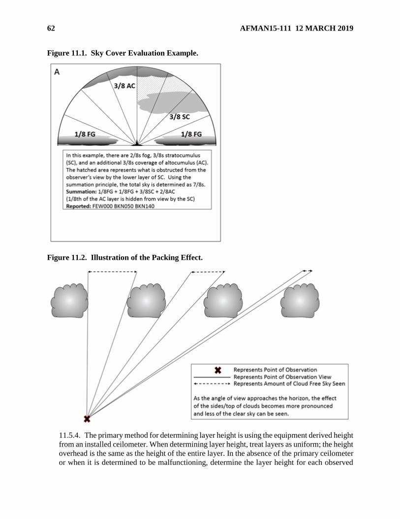
62 AFMAN15-111 12 MARCH 2019
Figure 11.1. Sky Cover Evaluation Example.
Figure 11.2. Illustration of the Packing Effect.
11.5.4. The primary method for determining layer height is using the equipment derived height
from an installed ceilometer. When determining layer height, treat layers as uniform; the height
overhead is the same as the height of the entire layer. In the absence of the primary ceilometer
or when it is determined to be malfunctioning, determine the layer height for each observed

AFMAN15-111 12 MARCH 2019 63
element using one of the following methods. Note: Determining layer height based on the
speed of movement of individual cloud elements is not a reliable method.
11.5.4.1. Deployable meteorological equipment such as an AN/TMQ-53 ceilometer.
11.5.4.2. A handheld ceilometer. When used, this device must be held as perpendicular to
the ground as possible and used only to measure cloud bases directly overhead. If held at
an angle, it erroneously displays heights as too great.
11.5.4.3. PIREPs from aircraft in the local area.
11.5.4.4. Known heights of unobscured portions of natural landmarks or objects.
11.5.4.5. Observation of a weather balloon; dew point depression from upper air profiles.
11.5.4.6. Convective Cloud Height Table. Use Table 11.4 to estimate the height of
cumulus clouds formed in the vicinity of the observing location. Note: This method is most
accurate in determining cloud bases below 5,000ft. This method cannot be used to
determine heights of non-cumuliform clouds or for locations in mountainous/hilly terrain.
Table 11.4. Convective Cloud Height Estimates.
CONVECTIVE CLOUD-BASE HEIGHT TABLE
Surface Dewpoint
Depression (°C)
Estimated Cloud
Base Height (ft)
Surface Dewpoint
Depression (°C)
Estimated Cloud
Base Height (ft)
0.5 200 10.5 4,200
1.0 400 11.0 4,400
1.5 600 11.5 4,600
2.0 800 12.0 4,800
2.5 1,000 12.5 5,000
3.0 1,200 13.0 5,200
3.5 1,400 13.5 5,400
4.0 1,600 14.0 5,600
4.5 1,800 14.5 5,800
5.0 2,000 15.0 6,000
5.5 2,200 15.5 6,200
6.0 2,400 16.0 6,400
6.5 2,600 16.5 6,600
7.0 2,800 17.0 6,800
7.5 3,000 17.5 7,000
8.0 3,200 18.0 7,200
8.5 3,400 18.5 7,400
9.0 3,600 19.0 7,600
9.5 3,800 19.5 7,800
10.0 4,000 20.0 8,000
64 AFMAN15-111 12 MARCH 2019
Chapter 12
TEMPERATURE AND DEW POINT
12.1. Introduction. This chapter describes the observing and reporting standards for
temperature and dew point. Temperature is a measure of the average kinetic energy of air
molecules. Dew point is the temperature that a parcel of air at a constant pressure and water vapor
content must be cooled, in order for saturation to occur.
12.2. Temperature/Dew Point Group (T'T'/T'dT'd). The temperature and dew point are
encoded as two digits rounded to the nearest whole degree Celsius. Subzero temperatures and dew
points will be prefixed with an M. (T-0).
12.2.1. Temperature is separated from the dew point by a slash (/). For example, a temperature
of 4C with a dew point of -2C is encoded as "04/M02." A temperature of -0.5C is encoded
as "M00." Exception: On the electronic (Excel®) AF Form 3803, use a minus sign (-) rather
than an M to indicate below zero temperature/dew points. The form macros will automatically
convert the minus sign to an M on the form while retaining the numerical value of the
temperature/dew point for calculations.
12.2.2. If the temperature is not available, the entire temperature/dew point group will not be
encoded. If the dew point is not available, the temperature is encoded followed by a slash (/)
and no entry will be made for dew point. For example, a temperature of 1.5C and a missing
dew point would be reported as "02/". (T-0).
12.3. Temperature/Dew Point Algorithms. The FBWOS continuously senses and measures
temperature and dew point and provides a report in degrees Celsius every minute. The 24-hr
maximum and minimum temperatures are based on the highest and lowest average temperatures
during the period of evaluation. Note: The AN/FMQ-19 stops reporting dew point when the
temperature is ≤ -34o Celsius.
12.4. Standards and Reporting. Temperature and dew point are primarily determined using an
FBWOS or other approved digital instrumentation. If no digital method is available, use any
backup means available.
12.4.1. All measurements are reported in degrees Celsius (C). Reports are to the nearest whole
degree in the body of all observations. Reports are to the nearest 1/10th of a degree in the
summary of the day section of the AF Form 3803 and the remarks section of an observation.
Reports are to the nearest whole degree on the JET Form 3813 due to system.
12.5. Manual Observing Methods.
12.5.1. The primary method to obtain temperature and dew point are by directly reading the
sensor output from an FBWOS. If using back-up equipment, follow the procedures in the
applicable T.O. or user’s manual.
12.5.2. The maximum and minimum temperatures are the highest and the lowest temperature
values respectively for the time period (hourly, 6-hr, 24-hr). Determine maximum and
minimum temperatures from a digital readout or temperature recording equipment. If no other
record is available, use the temperature entries recorded in the observations (24-hour observing
locations only).

AFMAN15-111 12 MARCH 2019 65
Chapter 13
PRESSURE
13.1. Introduction. This chapter describes the observing and reporting standards for pressure
measurements. All pressure values are initially derived from the atmospheric pressure as measured
by a barometer and may be reported in either inches of mercury (iHg) or hectopascals (hPa).
13.2. Altimeter (APHPHPHPH). The altimeter group always starts with an A (the international
indicator for altimeter in inches of mercury). The altimeter is encoded as a four-digit group
immediately following the A using the tens, units, tenths, and hundredths of inches of mercury.
The decimal point is not encoded.
13.3. Pressure Measurement Algorithms. The FBWOS sensors measure the barometric
pressure and then based on that value, compute the pressure parameters (e.g., station pressure,
altimeter setting, and sea-level pressure). Computations are made each minute. In addition to the
pressure parameters, the FBWOS also generates pressure change and pressure tendency remarks
for possible inclusion in the observations. FBWOS pressure sensors are capable of measuring
pressure from 17.5 to 32.5 iHg (600 to 1,100 hPa).
13.4. Standards and Reporting. At a minimum, all observations will include an altimeter
setting (ALSTG) in the body of the observation; additional pressure computations are recorded
and reported in accordance with this manual and local directives. (T-1). All pressure values will
be rounded down to the nearest reportable value. (T-1). In the United States and at US military
organizations overseas, pressure data is expressed as iHg for station pressure and ALSTGs and as
hPa for sea-level pressure (SLP); however, MAJCOMs may direct the use of hPa for reporting
purposes. Note: The common international unit of measure is hPa for all pressure data.
13.4.1. All pressure-related values are considered estimated any time the readings are suspect
in the opinion of weather personnel or when pressure is obtained through any method other
than the primary sensor. Exception: The AN/TMQ-53 may be used as a back-up without
estimating pressure values if it has been set-up and properly maintained IAW FCMS4-1994
and the T.O., and the values are representative and consistent with other reports in the area.
13.4.2. The primary measurements of atmospheric pressure used in observations are the
station pressure and the altimeter setting.
13.4.2.1. Station pressure is defined as the atmospheric pressure computed for the level of
the station elevation. This initial pressure calculation is used to derive all other pressure
reports. Station pressure is not disseminated but is recorded at 3-hourly intervals on the
observation form. Note: Station pressure may be referred to by the acronym “QFE” by the
international community.
13.4.2.2. The altimeter setting is a computed pressure value that an aircraft altimeter scale
is set to so it indicates the altitude above MSL of an aircraft on the ground at the location
for which the value was determined. Note: The letter “A” is used to identify an ALSTG in
observations at CONUS locations and OCONUS US military locations. The letter “Q” is
used by the international community; additionally, an ALSTG may be referred to by the
acronym “QNH.”

66 AFMAN15-111 12 MARCH 2019
13.4.3. Additional derived pressure-related reports are added to observations when occurring
and/or at regular intervals in accordance with this manual, higher headquarters guidance, and
local procedures. These reports include but are not limited the following:
13.4.3.1. Sea-level Pressure (SLP) is a report of the theoretical reduction of station
pressure to sea level. Where the earth’s surface is above sea level, it is assumed the
atmosphere extends to sea level below the observing location and the properties of the
hypothetical atmosphere are related to conditions observed at the unit. Note: SLP may be
referred to by the acronym “QFF” by the international community.
13.4.3.2. Pressure tendency is a coded report (5-group) included on the 3-hourly
observations that indicates the characteristic and amount of pressure change during the 3-
hour period preceding the observation.
13.4.3.3. Pressure falling rapidly (PRESFR) and pressure rising rapidly (PRESRR) are
remarks used to indicate a rapid fluctuation in pressure has occurred. These remarks are
reported in column 13 whenever the station pressure changes at a rate of at least 0.06 iHg
per hour (0.01 iHg per 10 minutes) with a change of at least 0.02 iHg having occurred at
the time of observation.
13.4.3.4. Pressure Altitude (PA) is an altitude in the standard atmosphere at which a given
pressure is observed. It is the indicated altitude above or below the 29.92 iHg constant-
pressure surface. Note: PA may be referred to by the acronym “QNE” by the international
community.
13.4.3.5. Density Altitude (DA) is the PA corrected for virtual temperature deviations
from the standard atmosphere.
13.4.3.6. Field Elevation (Ha) is the officially designated elevation of an airfield/site above
mean sea level. It is the elevation of the highest point on any of the runways of the
airfield/site.
13.4.3.7. Station Elevation (Hp) is the officially designated height above sea level to which
station pressure pertains; generally, the same as field elevation.
Table 13.1. Units of Measure and Resolution of Pressure Parameters.
Parameter Unit of Measure Resolution
Station Pressure Inches of Mercury 0.005 iHg
Altimeter Setting Inches of Mercury 0.01 iHg
Sea Level Pressure Hectopascals 0.1 hPa
Pressure Altitude Feet 10 ft
Density Altitude Feet 10 ft
13.5. Manual Observing Methods. All organizations with a permanent weather observing
mission in direct support of flying operations will have a primary pressure measurement instrument
and will designate a back-up pressure measuring instrument. (T-1). The primary method to obtain
pressure measurements are by directly reading the sensor output from an FBWOS or its associated
software (i.e. JET).

AFMAN15-111 12 MARCH 2019 67
13.5.1. Pressure Measurement Instrumentation. Obtain pressure data using an instrument from
the following priority list. When using back-up equipment, follow the procedures in the
applicable T.O. or user’s manual and treat all values as estimated (see paragraph 13.4.1 for
exception).
13.5.1.1. AN/FMQ-19, Automatic Meteorological Station (AMS).
13.5.1.2. AN/FMQ-22/23 AMS.
13.5.1.3. Automated Surface Observing System (ASOS).
13.5.1.4. AN/TMQ-53, Tactical Meteorological Observing System.
13.5.1.5. Altimeter Setting Indicator (ASI).
13.5.1.6. Aircraft altimeter.
13.5.1.7. Other MAJCOM-approved device.
13.5.2. Station Pressure. Determine the station pressure by taking a direct reading, and if
necessary, applying the posted pressure correction obtained during a scheduled barometer
comparison.
13.5.3. Altimeter Setting. Read directly from the pressure measuring device.
13.5.3.1. If a direct readout of the primary method is unavailable, ASLTG is computed
using the current station pressure value and the locally designated method (e.g. online
forecaster tools found on AFW-WEBS and OWS websites, pressure reduction calculator,
ALSTG quick reference chart).
13.5.3.2. If required for international aviation purposes, use Table 13.2 to convert values
from iHg to hPa.

68 AFMAN15-111 12 MARCH 2019
Table 13.2. ALSTG - iHg to hPa.
IHg 0.00 0.01 0.02 0.03 0.04 0.05 0.06 0.07 0.08 0.09
Hectopascals
28.0 948 948 948 949 949 949 950 950 950 951
28.1 951 951 952 952 952 953 953 953 954 954
28.2 955 955 955 956 956 956 957 957 957 958
28.3 958 958 959 959 959 960 960 960 961 961
28.4 961 962 962 962 963 963 963 964 964 964
28.5 965 965 965 966 966 966 967 967 967 968
28.6 968 968 969 969 969 970 970 970 971 971
28.7 971 972 972 972 973 973 973 974 974 974
28.8 975 975 976 976 976 977 977 977 978 978
28.9 978 979 979 979 980 980 980 981 981 981
29.0 982 982 982 983 983 983 984 984 984 985
29.1 985 985 986 986 986 987 987 987 988 988
29.2 988 989 989 989 990 990 990 991 991 991
29.3 992 992 992 993 993 993 994 994 994 995
29.4 995 995 996 996 997 997 997 998 998 998
29.5 999 999 999 1000 1000 1000 1001 1001 1001 1002
29.6 1002 1002 1003 1003 1003 1004 1004 1004 1005 1005
29.7 1005 1006 1006 1006 1007 1007 1007 1008 1008 1008
29.8 1009 1009 1009 1010 1010 1010 1011 1011 1011 1012
29.9 1012 1012 1013 1013 1013 1014 1014 1014 1015 1015
30.0 1015 1016 1016 1016 1017 1017 1018 1018 1018 1019
30.1 1019 1019 1020 1020 1020 1021 1021 1021 1022 1022
30.2 1022 1023 1023 1023 1024 1024 1024 1025 1025 1025
30.3 1026 1026 1026 1027 1027 1027 1028 1028 1028 1029
30.4 1029 1029 1030 1030 1030 1031 1031 1031 1032 1032
30.5 1032 1033 1033 1033 1034 1034 1034 1035 1035 1035
30.6 1036 1036 1036 1037 1037 1037 1038 1038 1038 1039
30.7 1039 1040 1040 1040 1041 1041 1041 1042 1042 1042
30.8 1043 1043 1043 1044 1044 1044 1045 1045 1045 1046
30.9 1046 1046 1047 1047 1047 1048 1048 1048 1049 1049
NOTE: The hPa values in this table are truncated to their reportable
value (i.e. rounded down to the nearest whole hPa)
13.5.4. Sea-Level Pressure. Determine the SLP by taking a direct reading from the FBWOS.
If a direct readout of the primary method is unavailable, SLP is computed using the current
station pressure and the locally designated method (e.g. online forecaster tools found on AFW-
WEBS and OWS websites, pressure reduction calculator, or SLP quick reference chart). Note:
In addition to when using back-up equipment, SLP is also considered estimated when the 12-
hour mean temperature is estimated.

AFMAN15-111 12 MARCH 2019 69
13.5.5. Pressure Tendency. Determine the pressure tendency by taking a direct reading from
the FBWOS during the 3-hourly observations.
13.5.5.1. If a direct readout of the pressure tendency is unavailable, compute the tendency
using the following procedures:
13.5.5.1.1. Determine the pressure tendency from the 3-hour trend of the ALSTGs.
Using the code figures in Table 13.3, choose the figure which best describes the
character of the change from the trend.
13.5.5.1.2. Determine the difference (without regard to positive or negative) in station
pressure from the 3-hour period to the nearest 0.005-inch by subtracting the current
station pressure from the station pressure from 3 hours ago. Use Table 13.4 to select
the code figure that corresponds to the net change. Note: Limited-duty units can access
the FBWOS software to obtain past pressure information when if available.
13.5.5.2. Consider the 3-hour pressure tendency group (5appp) as indeterminable when
any portion of the group is impossible to determine. Annotate the reason for not reporting
the group in column 90 (e.g. sensor outage).
Table 13.3. Pressure Tendency Character.
General Description Pressure Characterization Code Figure
Atmospheric pressure
now higher than 3 hours
ago
Increasing, then decreasing 0
Increasing, then steady, or increasing then increasing
more slowly
1
Increasing steadily or unsteadily 2
Decreasing or steady, then increasing; or increasing
then increasing more rapidly
3
Atmospheric pressure
now same as 3 hours ago
Increasing, then decreasing 0
Steady 4
Decreasing, then increasing 5
Atmospheric pressure
now lower than 3 hours
ago
Decreasing, then increasing 5
Decreasing, then steady; or decreasing then
decreasing more slowly
6
Decreasing steadily or unsteadily 7
Steady or increasing, then decreasing; or decreasing
then decreasing more rapidly
8

70 AFMAN15-111 12 MARCH 2019
Table 13.4. Amount of Pressure Change in Last 3 Hours.
Code figure, Difference in Pressure (iHg and hPa)
Code
Figure
Inches
of Hg
hPa Code
Figure
Inches
of Hg
hPa Code
Figure
Inches
of Hg
hPa Code
Figure
Inches
of Hg
hPa
000 .000 0.0 051 .150 5.1 102 .300 10.2 152 .450 15.2
002 .005 0.2 052 .155 5.2 103 .305 10.3 154 .455 15.4
003 .010 0.3 054 .160 5.4 105 .310 10.5 156 .460 15.6
005 .015 0.5 056 .165 5.6 107 .315 10.7 157 .465 15.7
007 .020 0.7 058 .170 5.8 108 .320 10.8 159 .470 15.9
008 .025 0.8 059 .175 5.9 110 .325 11.0 161 .475 16.1
010 .030 1.0 061 .180 6.1 112 .330 11.2 163 .480 16.3
012 .035 1.2 063 .185 6.3 113 .335 11.3 164 .485 16.4
014 .040 1.4 064 .190 6.4 115 .340 11.5 166 .490 16.6
015 .045 1.5 066 .195 6.5 117 .345 11.7 168 .495 16.8
017 .050 1.7 068 .200 6.8 119 .350 11.9 169 .500 16.9
019 .055 1.9 069 .205 6.9 120 .355 12.0 171 .505 17.1
020 .060 2.0 071 .210 7.1 122 .360 12.2 173 .510 17.3
022 .065 2.2 073 .215 7.3 124 .365 12.4 174 .515 17.4
024 .070 2.4 075 .220 7.5 125 .370 12.5 176 .520 17.6
025 .075 2.5 076 .225 7.6 127 .375 12.7 178 .525 17.8
027 .080 2.7 078 .230 7.8 129 .380 12.9 179 .530 17.9
029 .085 2.9 080 .235 8.0 130 .385 13.0 181 .535 18.1
030 .090 3.0 081 .240 8.1 132 .390 13.2 183 .540 18.3
032 .095 3.2 083 .245 8.3 134 .395 13.4 185 .545 18.5
034 .100 3.4 085 .250 8.5 135 .400 13.5 186 .550 18.6
036 .105 3.6 086 .255 8.6 137 .405 13.7 188 .555 18.8
037 .110 3.7 088 .260 8.8 139 .410 13.9 190 .560 19.0
039 .115 3.9 090 .265 9.0 141 .415 14.1 191 .565 19.1
041 .120 4.1 091 .270 9.1 142 .420 14.2 193 .570 19.3
042 .125 4.2 093 .275 9.3 144 .425 14.4 195 .575 19.5
044 .130 4.4 095 .280 9.5 146 .430 14.6 196 .580 19.6
046 .135 4.6 097 .285 9.7 147 .435 14.7 198 .585 19.8
047 .140 4.7 098 .290 9.8 149 .440 14.9 200 .590 20.0
049 .145 4.9 100 .295 10.0 151 .445 15.1 201 .595 20.1
203 .600 20.3
NOTE: Code figures in this table are based on the conversion from inches of mercury to
hectopascals since station pressure is taken in inches of mercury. However, other code figures
not listed (e.g., 016 for 1.6 hPa) are also used at locations where station pressure is determined in
hectopascals.
13.5.6. Pressure Altitude (PA) and Density Altitude (DA). PA and DA are automatically
computed by FBWOSs, displayed on the ADS (e.g., JET) and TMQ-53 sensor displays, and
disseminated locally to ATC agencies. If a direct readout of the primary method is unavailable,
PA and DA can also be computed using the OWS or AFW-WEBS Forecaster Tools..

AFMAN15-111 12 MARCH 2019 71
13.5.6.1. FBWOS and JET software compute DA using different formulas; the formula
used by JET takes into account water vapor and the FBWOS does not. AF weather
organizations should provide their supported units with DA values obtained directly from
the ADS and TMQ-53 sensor displays when available. (T-3).
13.5.6.2. When the primary pressure sensor is inoperative, notify ATC agencies that the
reported PA and DA values are estimated.
13.5.7. Rapid Pressure Changes. The FBWOS/JET automatically enter this remark if the
condition is detected. If unavailable, manually determine whether the pressure change at the
time of an observation and report the condition in the remarks of the observation using the
format in Attachment 3.
13.6. Comparison and Calibration Procedures. Each unit with an AN/TMQ-53, a hand-held
barometer, and/or equivalent will establish a barometer comparison/calibration program. (T-3).
Note: Comparisons should be delayed during periods of high wind speeds (25 knots or higher,
sustained or gusting), rapid temperature changes or steep horizontal and/or vertical temperature
gradients (i.e. frontal system in area or frontal passage).
13.6.1. Record and document barometer comparisons on a locally developed
worksheet/spreadsheet, or MAJCOM or higher headquarters approved
form/worksheet/spreadsheet. Retain the last two barometer comparisons on file and dispose of
all others.
13.6.2. Deployable barometers (e.g., AN/TMQ-53, handheld barometer).
13.6.2.1. At a minimum, compare barometers against a standard barometer annually,
before deployment, when first deployed, if relocated during a deployment, and as soon as
practical after redeployment.
13.6.2.2. Determine a mean correction by making at least four comparisons, not less than
15 minutes apart, against the standard barometer.
13.6.2.2.1. For handheld barometers, the standard barometer is the local observing
system (i.e., AN/FMQ-19, AN/FMQ-23, or AN/TMQ-53).
13.6.2.2.2. For the AN/TMQ-53, the standard barometer can be either the local
observing system or, when available, a maintenance standard barometer (used by
airfield systems/depot maintenance personnel).
13.6.2.3. Apply the mean correction (or adjust the software to reflect the correction) to a
fifth pressure reading. If the corrected reading differs from the standard barometer by more
than 0.01iHg (0.34hPa), re-accomplish the steps above. If the corrected reading exceeds
0.03iHg (1.01hPa), discontinue use and replace the device (for the AN/TMQ-53, turn in to
depot maintenance).

72 AFMAN15-111 12 MARCH 2019
13.6.2.4. At locations that do not have a standard barometer, and while deployed, compare
each barometer against any available calibrated pressure instrument (e.g., aircraft altimeter)
following the same procedures above.
MARK D. KELLY, Lt Gen, USAF
Deputy Chief of Staff, Operations
AFMAN15-111 12 MARCH 2019 73
Attachment 1
GLOSSARY OF REFERENCES AND SUPPORTING INFORMATION
References
AFPD 15-1, Weather Operations, 12 November 2015
AFI 11-201, Flight Information Publication, 31 March 2009
AFI 11-202, Volume 3, General Flight Rules, 10 August 2016
AFI 13-204, Volume 3, Airfield Operations Procedures and Programs, 1 September 2010
AFI 15-127, Weather Training, 14 March 2012
AFI 15-128, Weather Force Structure, 7 February 2011
AFI 21-103, Equipment Inventory, Status and Utilization Reporting, 26 January 2012
AFI 33-360, Publications and Forms Management, 1 December 2015
AFMAN 15-129, Volume 2, Air and Space Weather Operations – Exploitation, 7 December
2011
AFMAN 33-363, Management of Records, 1 March 2008
AR 95-1, Flight Regulations, 22 March 2018
AR 95-2, Airspace, Airfields/Heliports, Flight Activities, Air Traffic Control, and Navigational
Aids, 31 March 2016
FAAO JO 6560.20C, Siting Criteria for Automated Weather Observing Systems, 6 September,
2017
FAAO JO 7340.2H, Contractions, 6 March 2018
FAAO JO 7350.9M, Location Identifiers, 18 July 2018
FAAO JO 7110.65X, Air Traffic Control, 12 September 2017
Federal Meteorological Handbook No. 1 (FCM-H1), Surface Weather Observations and Reports,
November 2017
FCM-S4-1994, Federal Standard for Siting Meteorological Sensors at Airports, August 1994
Qualification Training Package Observing, Trainer’s Guide, 15 February 2010
TC 3-04.81, Air Traffic Control Facility Operations, Training, Maintenance, and
Standardization, 29 October 2010
WMO-No. 306, Manual on Codes, Vol I, International Codes, 2011 Edition
WMO-No. 306, Manual on Codes, Vol II, Regional Codes and National Coding Practices, 2011
Edition
WMO-No. 407, International Cloud Atlas, Volume II, 1987
Prescribed Forms
AF Form 3803 – Surface Weather Observations (METAR/SPECI), 01 August 2000

74 AFMAN15-111 12 MARCH 2019
JET Form 3818 – Surface Weather Observations (METAR/SPECI), 01 August 2000
Adopted Forms
AF 679 – Air Force Publication Compliance Item Waiver Request/Approval, 09 May 2018
AFTO 747 – Cyberspace Infrastructure System Acceptance, 18 February 2016
AF 847 – Recommendation for Change of Publication, 22 September 2009
AF 3622 – Air Traffic Control/Weather Certification and Rating Record, 15 May 2018
AF Form 4058 – Airfield Operations Policy Waiver, 01 May 2001
Abbreviations and Acronyms
Minus “-“—Light intensity
no symbol—Moderate intensity
Plus “+”—Heavy intensity
Forward slash “/”—Indicates visual range data follows; separator between temperature and dew
point data
ACC—Altocumulus Castellanus
ACFT MSHP—Aircraft Mishap
ACSL—Altocumulus Standing Lenticular Cloud
ADS—Automated Dissemination System
AFW-WEBS—Air Force Weather Web Services
ALSTG—Altimeter Setting
AO1—ASOS/AWOS stations without a precipitation discriminator
AO2—Remark included in METAR/SPECI observations from FBWOS WFs/Dets without
augmentation (or ASOS/AWOS stations with a precipitation discriminator)
AO2A—Remark included in METAR/SPECI observations from FBWOS WFs/Dets with manual
augmentation
AOL—Alternate Operating Location
APRNT—Apparent
APRX—Approximately
ASOS—Automated Surface Observing System
ATC—Air Traffic Control
AURBO—Aurora
AUTO—Automated Report
B—Began
BC—Patches

AFMAN15-111 12 MARCH 2019 75
BKN—Broken
BL—Blowing
BR—Mist
C—Center (With Reference To Runway Designation)
CB—Cumulonimbus Cloud
CBMAM—Cumulonimbus Mammatus Cloud
CCSL—Cirrocumulus Standing Lenticular Cloud
CHI—Cloud-Height Indicator
CHINO—Cloud-height-indicator, Sky Condition At Secondary Location Not Available
CIG—Ceiling
CLR—Clear
CONTRAILS—Condensation Trails
CONUS—Continental United States
COR—Correction to A Previously Disseminated Report
DoD—Department Of Defense
DR—Low Drifting
DS—Dust storm
DSNT—Distant
DU—Widespread Dust
DZ—Drizzle
E—East, Ended
ESTMD—Estimated
FAA—Federal Aviation Administration
FBWOS—Fixed Base Weather Observing System
FC—Funnel Cloud
FEW—Few Clouds
FG—Fog
FIBI—Filed But Impracticable To Transmit
FIRST—First Observation After A Break In Coverage At An Augmented Observing
FLIP—Flight Information Publication
FROPA—Frontal Passage
FT—Feet

76 AFMAN15-111 12 MARCH 2019
FU—Smoke
FZ—Freezing
FZRANO—Freezing Rain Information Not Available
G—Gust
GR—Hail (any size)
GS—Snow Pellets
hPa—Hectopascals (millibars)
HZ—Haze
IAW—In Accordance With
IC—Ice Crystals
ICAO—International Civil Aviation Organization
IFR—Instrument Flight Rules
ILS—Instrument Landing System
JET—Joint Environmental Toolkit
KT—Knots
L—Left (With Reference To Runway Designation)
LAST—Last Observation Before A Break In Coverage At An Augmented Observing
LOC—Location
LST—Local Standard Time
LTG—Lightning
LWR—Lower
M—Minus, Less Than
MAJCOM—Major Air Force Command
METAR—Aviation Routine Weather Report
MI—Shallow
MMLS—Mobile Microwave Landing System
MOV—Move, Moving, Moved
MT—Mountains
N—North
N/A—Not Applicable
NE—Northeast
NW—Northwest
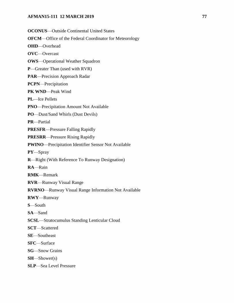
AFMAN15-111 12 MARCH 2019 77
OCONUS—Outside Continental United States
OFCM—Office of the Federal Coordinator for Meteorology
OHD—Overhead
OVC—Overcast
OWS—Operational Weather Squadron
P—Greater Than (used with RVR)
PAR—Precision Approach Radar
PCPN—Precipitation
PK WND—Peak Wind
PL—Ice Pellets
PNO—Precipitation Amount Not Available
PO—Dust/Sand Whirls (Dust Devils)
PR—Partial
PRESFR—Pressure Falling Rapidly
PRESRR—Pressure Rising Rapidly
PWINO—Precipitation Identifier Sensor Not Available
PY—Spray
R—Right (With Reference To Runway Designation)
RA—Rain
RMK—Remark
RVR—Runway Visual Range
RVRNO—Runway Visual Range Information Not Available
RWY—Runway
S—South
SA—Sand
SCSL—Stratocumulus Standing Lenticular Cloud
SCT—Scattered
SE—Southeast
SFC—Surface
SG—Snow Grains
SH—Shower(s)
SLP—Sea Level Pressure

78 AFMAN15-111 12 MARCH 2019
SLPNO—Sea Level Pressure Not Available
SM—Statute Miles
SN—Snow
SNINCR—Snow Increasing Rapidly
SPECI—Aviation Selected Special Weather Report
SQ—Squall
SS—Sandstorm
SW—Southwest
SWAP—Severe Weather Action Plan
TCU—Towering Cumulus
TO—Technical Order
TS—Thunderstorm
TSNO—Thunderstorm Information Not Available
TWR—Tower
UNKN—Unknown
UP—Unknown Precipitation
UTC—Coordinated Universal Time
V—Variable
VA—Volcanic Ash
VC—In the Vicinity
VFR—Visual Flight Rules
VIS—Visibility
VISNO—Visibility at Secondary Location Not Available
VRB—Variable
VV—Vertical Visibility
W—West
WF/Det—Weather Flight/Detachment
WMO—World Meteorological Organization
WND—Wind
WSHFT—Wind Shift
Z—Zulu (e.g., Coordinated Universal Time)

AFMAN15-111 12 MARCH 2019 79
Terms
Additive Data—A group of coded remarks that includes pressure tendency, amount of
precipitation, and maximum/minimum temperature during specified periods of time.
Aviation Routine Weather Report—The WMO METAR code format used worldwide to encode
weather observations.
Eyes Forward—WF/Det technicians are the eyes forward for the OWS forecasters and integrate
weather radar data, meteorological satellite imagery, lightning detection readouts, and non-
standard weather data systems (vertical profilers, mesonet data, etc.) to create an integrated
weather picture and near-term trend forecasts for the OWS. Eyes forward yields meaningful
meteorological information not contained in coded observations to the servicing OWS and is an
integral part of the meteorological watch for an installation or contingency operating location.
File Time—The specific time or specific time block a weather message or bulletin is scheduled to
be transmitted.
Freezing Rain—Rain that falls in liquid form but freezes upon impact to form a coating of glaze
upon the ground and on exposed objects.
Glaze—A coating of ice formed by freezing precipitation covering the ground or exposed objects.
ICAO Identifier—A specifically authorized 4-letter identifier assigned to a location and
documented in ICAO Document 7910.ICAO.
International Civil Aviation Organization—A United Nations organization specializing in
matters dealing with international aviation and navigation.
Joint Environmental Toolkit (JET)—JET consolidates and integrates key capabilities from
several familiar systems (N-TFS, OPS-II, JWIS, AOS, IWWC, IWEDA, IMETS…) used in
OWSs, WFs/Dets, AOCs, and even deployed into one seamless application.
Limited-Duty Unit—A WF/Det that provides less than 24-hour a day forecast service.
Longline—dissemination of a surface weather observation outside of local installation.
Notice to Airmen (NOTAM)—A timely notice containing information concerning the
establishment, condition, or change in any aeronautical facility, service, procedures, or hazards,
essential to personnel concerned with flight operations.
Observed—Indicates reported weather information was determined visually by weather
personnel, or weather sensing equipment, or by using radar.
Pilot Report (PIREP)—A report of in-flight weather provided by an aircraft crewmember.
Severe Weather—Any weather condition that poses a hazard to property or life.

Attachment 2
SPECIAL (SPECI) CRITERIA
Table A2.1. SPECI Criteria.
Referen
ce
Nu
mb
er Criteria Pertinent data
Man
ual
Au
tom
ated
Su
pp
lemen
t
Back
-up
1 Visibility decreases to less than or, if
below, increases to equal or exceed:
(1) 3SM/4800 m
(See Notes 1 and 8).
(2) 2SM/3200 m (See Note 4).
(3) 1½SM/2400 m (See Note 5).
(4) 1 statute mile/1600 m (See Note 1).
(5) ¾ statue mile/1200 m (See Note 10).
(6) ½ statute mile/800 m (See Note 6).
(7) ¼ statute mile/400 m (See Note 6).
(8) All published airfield landing minima
(including circling), as listed in the DoD
FLIPs, aircraft-specific AFI 11-2 Series
Volume 3, MAJCOM supplements, and
Service publications applicable to aircraft
Surface visibility as reported in the
body of the report decreases to less
than or, if below, increases to equal
or exceed.
X X X X

AFMAN15-111 12 MARCH 2019 81
Referen
ce
Nu
mb
er Criteria Pertinent data
Man
ual
Au
tom
ated
Su
pp
lemen
t
Back
-up
assigned to the installation (See Note 9).
If none is published, use ½ mile/800 m
(See Notes 1 and 6).
(9) Visibility minima as applicable to
range support, covered in governing
directives and support agreements.
(10) All airfield takeoff minima
published in DoD FLIPs.
2 Ceiling decreases to less than or, if below,
increases to equal or exceed:
(1) 3000 feet (See Note 1).
(2) 2000 feet (See Note 10).
(3) 1500 feet (See Note 1).
(4) 1000 feet (See Note 2).
(5) 800 feet (See Note 2).
(6) 700 feet (See Note 4).
(7) 500 feet (See Note 1).
The ceiling (rounded off to
reportable values) forms or
dissipates below, decreases to less
than, or if below, increases to equal
or exceed stated criteria.
X X X X

82 AFMAN15-111 12 MARCH 2019
Referen
ce
Nu
mb
er Criteria Pertinent data
Man
ual
Au
tom
ated
Su
pp
lemen
t
Back
-up
(8) 300 feet (See Note 5).
(9) 200 feet (See Note 6).
(10) 100 feet (See Note 6).
(11) All published airfield landing
minima (including circling), as listed in
DoD FLIPs and appropriate USAF, Army,
or MAJCOM flying instructions and
publications. If none published, use 200
feet (See Note 7).
(12) Ceiling minima, as applicable to
range support, covered in governing
directives and support agreements.
(13) All airfield takeoff minima as
published in the DoD FLIPs.
(14) All other landing, takeoff, and pilot-
restrictions for ceiling published in
aircraft-specific AFI 11-2 Series Volume
3, MAJCOM supplements, and Service
publications applicable to aircraft
assigned to the installation.
3 Sky Condition A layer of clouds or obscuring
phenomena aloft is observed below X X O X

AFMAN15-111 12 MARCH 2019 83
Referen
ce
Nu
mb
er Criteria Pertinent data
Man
ual
Au
tom
ated
Su
pp
lemen
t
Back
-up
the highest published instrument
landing minimum (including
circling) applicable to the airfield,
and no layer aloft was reported
below this height in the previous
METAR or SPECI.
4 Wind Shift Wind direction changes by 45
degrees or more in less than 15
minutes and the wind speed is 10
knots or more throughout the wind
shift.
X X O X
5 Squall When squalls occur. X X O X
6 Volcanic Eruption
(See Remark 1, Table A3.1)
Eruption or volcanic ash cloud first
noted. X M X X
7 Thunderstorm (occurring on station)
(1) Begins.
(2) Ends.
A SPECI is not required to report
the beginning of a new
thunderstorm if one is currently
reported.
X X X X
8 Precipitation
(1) Hail begins or ends.
(2) Freezing precipitation begins, ends, or
changes intensity.
Note: Except for freezing rain,
freezing drizzle, hail, and ice
pellets, a SPECI is not required for
changes in type (e.g., drizzle
changing to snow grains) or the
beginning or ending of one type
while another is in progress (e.g.,
snow changing to rain and snow).
X
X
X
M
M
M
X
X
X
X
X
X

84 AFMAN15-111 12 MARCH 2019
Referen
ce
Nu
mb
er Criteria Pertinent data
Man
ual
Au
tom
ated
Su
pp
lemen
t
Back
-up
(3) Ice pellets begin, end, or change
intensity.
(4) Any other type of precipitation begins
or ends (N/A for ASOS).
X
X
O
X
9 Tornado, Funnel Cloud, or Waterspout
(1) Is observed.
(2) Disappears from sight or ends.
X M X X
10 Runway Visual Range (RVR)
(1) RVR for the active runway decreases
to less than or, if below, increases to equal
or exceed:
(a) 6000 feet (P1500 m for FBWOS
sensors, 1830 m for ASOS sensors)
(b) 5000 feet (1500 m for FBWOS
sensors, 1520 m for ASOS sensors)
(c) 4000 feet (1300 m), touch and go
landing mins in 11 Series AFIs for
mutiple platforms.
The highest value during the
preceding 10 minutes from the
designated RVR runway decreases
to less than, or if below, increases to
equal or exceed.
Note: The RVR SPECI
observations is taken, but only
transmitted longline at locations
with a 10-minute RVR average
readout capability.
X

AFMAN15-111 12 MARCH 2019 85
Referen
ce
Nu
mb
er Criteria Pertinent data
Man
ual
Au
tom
ated
Su
pp
lemen
t
Back
-up
(d) 2400 feet (750 m for FBWOS
sensors, 0730 m for ASOS sensors), PAR
approaches for mutiple platforms
(e) 2000 feet (600 m for FBWOS sensors,
0610 m for ASOS sensors)
Required for CAT I and II ILS
Localizer Critical Areas, Precision
Approach Radar (PAR) Touchdown
Areas, and MMLS Azimuth Critical
Area.
(f) 1600 feet (400 m), required for
multiple platforms in 11 Series AFIs.
(g) 1200 feet (400 m), CAT II ILS
approach mins.
(h) 1000 feet (320 m), required in
multiple 11 Series AFIs
(i) 600 feet (200 m), operational takeoff
mins in 11 Series AFI
(j) All published RVR minima applicable
to the runway in use.

86 AFMAN15-111 12 MARCH 2019
Referen
ce
Nu
mb
er Criteria Pertinent data
Man
ual
Au
tom
ated
Su
pp
lemen
t
Back
-up
(2) RVR is first determined as
unavailable (RVRNO) for the runway in
use, and when it is first determined that
the RVRNO report is no longer
applicable, provided conditions for
reporting RVR exist.
11 Tower Visibility Transmit a SPECI with the
tower visibility as a remark:
(1) When notified by the control
tower that tower visibility has
decreased to less than or, if below,
increased to equal or exceed 1, 2, or
3SM, 1600, 3200 or 4800 m (IAW
FAA JO 7110.65X, Air Traffic
Control) and the control tower
visibility differs from the prevailing
visibility.
(2) When notified by the control
tower that tower visibility has
decreased to less than or, if below,
increased to equal or exceed locally
developed tower special criteria (if
applicable) and the control tower
visibility differs
from the prevailing visibility.
X M X X
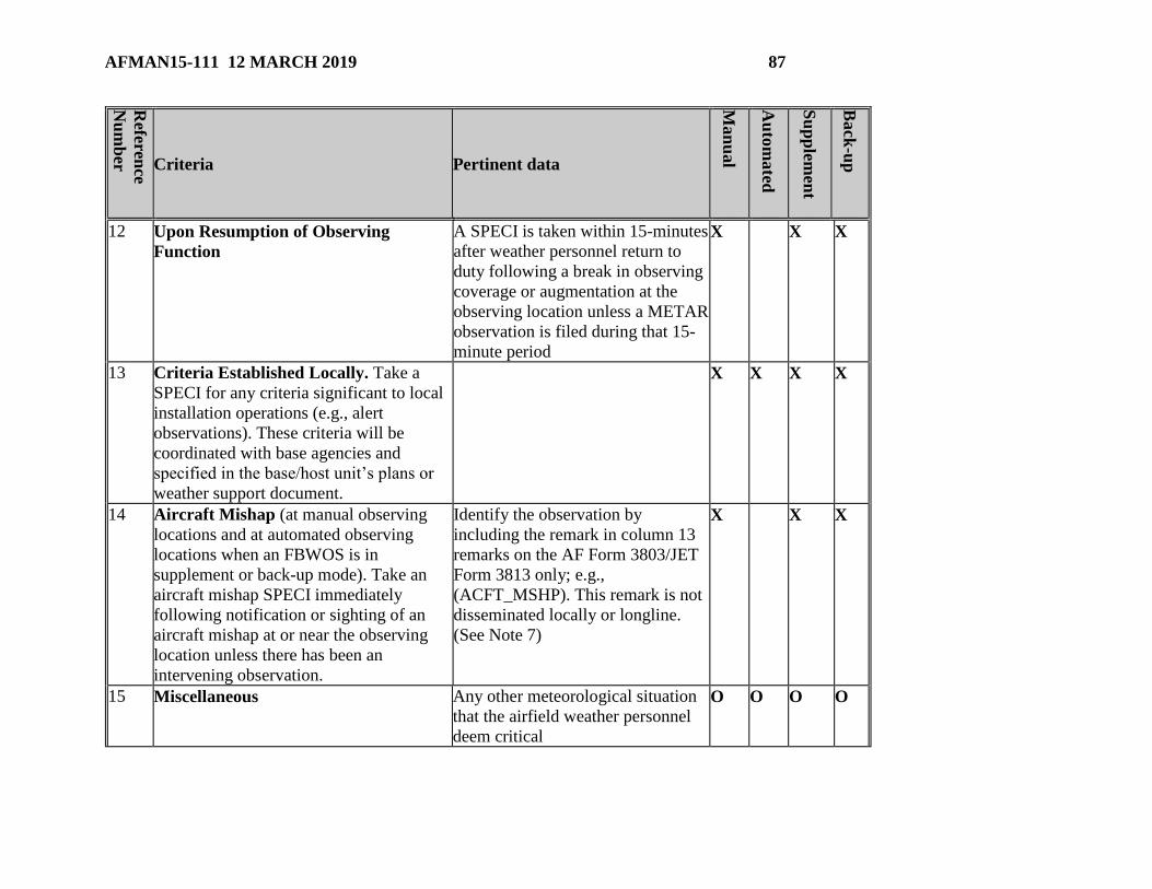
AFMAN15-111 12 MARCH 2019 87
Referen
ce
Nu
mb
er Criteria Pertinent data
Man
ual
Au
tom
ated
Su
pp
lemen
t
Back
-up
12 Upon Resumption of Observing
Function
A SPECI is taken within 15-minutes
after weather personnel return to
duty following a break in observing
coverage or augmentation at the
observing location unless a METAR
observation is filed during that 15-
minute period
X X X
13 Criteria Established Locally. Take a
SPECI for any criteria significant to local
installation operations (e.g., alert
observations). These criteria will be
coordinated with base agencies and
specified in the base/host unit’s plans or
weather support document.
X X X X
14 Aircraft Mishap (at manual observing
locations and at automated observing
locations when an FBWOS is in
supplement or back-up mode). Take an
aircraft mishap SPECI immediately
following notification or sighting of an
aircraft mishap at or near the observing
location unless there has been an
intervening observation.
Identify the observation by
including the remark in column 13
remarks on the AF Form 3803/JET
Form 3813 only; e.g.,
(ACFT_MSHP). This remark is not
disseminated locally or longline.
(See Note 7)
X X X
15 Miscellaneous Any other meteorological situation
that the airfield weather personnel
deem critical
O O O O

88 AFMAN15-111 12 MARCH 2019
Referen
ce
Nu
mb
er Criteria Pertinent data
Man
ual
Au
tom
ated
Su
pp
lemen
t
Back
-up
NOTES:
X – Indicates required data
O – Indicates optional data based on local operational requirements
M – Indicates Mandatory Supplementary Weather Conditions. When weather personnel are on duty, switch
FBWOS to augment mode and begin supplementation operations.
1. OFCM policy, FAA policy, and mutiple MAJCOM 11 Series AFI supplements
2. FAA Aeronautical Information Manual requires 1000-ft ceilings for VFR ops in controlled airspace
3. Ceilings required by AFI 13-204, Volume 3; required for ground ops decisions; visibility required for
OFCM and FAA policy
4. Ceiling and visibility required in mutiple MAJCOM 11 Series AFI supplements, visibility required in
FAA and OFCM policy.
5. Required in mutiple MAJCOM 11 Series AFI supplements.
6. Required in AR 95-1, Aviation Flight Regulations, fixed wing and helicopter minimums, departure
requirement if RVR is not available for multiple 11 series AFIs. 400-meter visibility is required if a blizzard
warning is required criteria for a location.
7. A SPECI observation is not required for in-flight emergencies, i.e., those declared to reflect an unsafe
condition that could adversely affect the safety of the aircraft. However, such in-flight emergencies should
alert weather personnel to intensify the weather watch to ensure maximum support to the aircraft in distress.
If the in-flight emergency results in an accident or incident, the aircraft mishap SPECI is then required.
8. Substitute 5000 m for 4800 m at OCONUS locations based on allied or host-nation practice
9. At airfields where takeoff/landing/circling minima are equal to non-reportable visibility values, units will
substitute the next lower reportable visibility value for their special criteria
10. Touch and go landing minimum for multiple platforms in 11 Series AFIs.
11. If in doubt, take the observation; also see Table 5.1.

AFMAN15-111 12 MARCH 2019 89
Attachment 3
REMARKS
Table A3.1. Automated, Manual, and Plain Language Remarks/Additive and Maintenance Data.
Rem
ark
Nu
mb
er
Observed
Condition Enter in Remarks Section
Man
ual
Au
tom
ated
Su
pp
lemen
t
Back
-up
1 Volcanic
Eruption
Report the following information, if known: (1) Name of
volcano, (2) Latitude and longitude or direction and distance
from the installation, (3) Date/time UTC of eruption, (4) Size
description, approximate height and direction of movement
of the ash cloud, (5) And any other pertinent data, e.g., MT
AUGUSTINE VOLCANO 70SM SW ERUPTED 231505
LARGE ASH CLOUD EXTENDING TO APRX 30000 FT
MOV NE.
X M X X
2 Tornadic
Activity
(See Note 1)
Encode tornadoes, funnel clouds, or waterspouts in format,
Tornadic activity_B/E(hh)mm_ LOC/DIR_(MOV), where
TORNADO, FUNNEL CLOUD, or WATERSPOUT
identifies the specific tornadic activity, B/E denotes the
beginning and/or ending time, (hh)mm is the time of
occurrence (only the minutes are required if the hour can be
inferred from the report time), LOC/DIR is the location
(distance if known) and/or direction of the phenomena from
the installation, and MOV is the movement, if known.
Tornadic activity will be encoded as the first remark after the
"RMK" entry. For example, "TORNADO B13 6 NE" would
indicate that a tornado, which began at 13 minutes past the
hour, was 6SM northeast of the observing location.
X M X X

90 AFMAN15-111 12 MARCH 2019
Rem
ark
Nu
mb
er
Observed
Condition Enter in Remarks Section
Man
ual
Au
tom
ated
Su
pp
lemen
t
Back
-up
3 Augmented or
Automated
Systems
(AO2 or AO2A). Encode AO2 in all METAR/SPECI from
FBWOSs without augmentation. Encode AO2A in all
METAR/SPECI from FBWOSs with manual augmentation.
Note: ASOS/AWOS stations without a precipitation
discriminator will report AO1; ASOS/AWOS stations with a
precipitation discriminator will report AO2.
X X X
4 Peak Wind Encode peak wind (> 25 knots) in format,
PK_WND_dddff(f)/(hh)mm of the next METAR, where
PK_WND is the remark identifier, ddd is the direction of the
peak wind, ff(f) is the peak wind speed since the last
METAR, and (hh)mm is the time of occurrence (only the
minutes are required if the hour can be inferred from the
report time). There will be a space between the two elements
of the remark identifier and the wind direction/speed group; a
slash "/" (without spaces) will separate the wind
direction/speed group and the time. This remark is still
required even if the peak wind speed was transmitted in an
intervening SPECI, but is not required if the peak wind
occurred and/or reoccurred during the 2-minute observation
period prior to the METAR. For example, a peak wind of 45
knots from 280 degrees that occurred at 15 minutes past the
hour would be encoded "PK WND 28045/15." Multiple
occurrence example: PK WND 24042/43 25042/19
(augmented mode). Note: FBWOS report the most recent
occurrence of the peak wind.
X X X
5 Wind Shift Encode wind shift ( 45 in less than 15 minutes with sustained
winds 10 kts) in format, WSHFT_(hh)mm, where WSHFT X X X
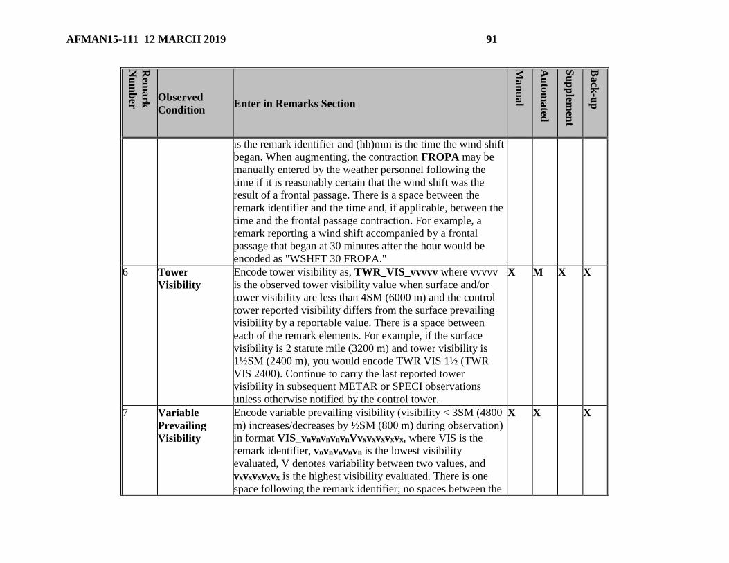
AFMAN15-111 12 MARCH 2019 91
Rem
ark
Nu
mb
er
Observed
Condition Enter in Remarks Section
Man
ual
Au
tom
ated
Su
pp
lemen
t
Back
-up
is the remark identifier and (hh)mm is the time the wind shift
began. When augmenting, the contraction FROPA may be
manually entered by the weather personnel following the
time if it is reasonably certain that the wind shift was the
result of a frontal passage. There is a space between the
remark identifier and the time and, if applicable, between the
time and the frontal passage contraction. For example, a
remark reporting a wind shift accompanied by a frontal
passage that began at 30 minutes after the hour would be
encoded as "WSHFT 30 FROPA."
6 Tower
Visibility
Encode tower visibility as, TWR_VIS_vvvvv where vvvvv
is the observed tower visibility value when surface and/or
tower visibility are less than 4SM (6000 m) and the control
tower reported visibility differs from the surface prevailing
visibility by a reportable value. There is a space between
each of the remark elements. For example, if the surface
visibility is 2 statute mile (3200 m) and tower visibility is
1½SM (2400 m), you would encode TWR VIS 1½ (TWR
VIS 2400). Continue to carry the last reported tower
visibility in subsequent METAR or SPECI observations
unless otherwise notified by the control tower.
X M X X
7 Variable
Prevailing
Visibility
Encode variable prevailing visibility (visibility < 3SM (4800
m) increases/decreases by ½SM (800 m) during observation)
in format VIS_vnvnvnvnvnVvxvxvxvxvx, where VIS is the
remark identifier, vnvnvnvnvn is the lowest visibility
evaluated, V denotes variability between two values, and
vxvxvxvxvx is the highest visibility evaluated. There is one
space following the remark identifier; no spaces between the
X X X

92 AFMAN15-111 12 MARCH 2019
Rem
ark
Nu
mb
er
Observed
Condition Enter in Remarks Section
Man
ual
Au
tom
ated
Su
pp
lemen
t
Back
-up
letter V and the lowest/highest values. For example, a
visibility that was varying between ½ and 2SM would be
encoded "VIS 1/2V2."
8 Sector
Visibility
Encode sector visibility (visibility in > 45° sector differs
from prevailing visibility by one or more reportable values
and either prevailing or sector visibility is < 3SM (4800 m) in
format, VIS_[DIR]_vvvvv_[Plain Language], where VIS is
the remark identifier, [DIR] defines the sector to 8 points of
the compass, and vvvvv is the sector visibility inSM or m,
using the appropriate set of values. For example, a visibility
of 2½SM (4000 m) in the northeastern octant would be
encoded "VIS NE 2 1/2" (VIS NE 4000).
O
9 Visibility at
Second
Location
Encode visibility at a second location in format
VIS_vvvvv_[LOC], where VIS is the remark identifier,
vvvvv is the measured visibility value, and [LOC] is the
specific location of the visibility sensor(s). Include the
remark only when the condition is lower than that contained
in the body of the report. For example, a visibility of 2½SM
(4000 m) measured by a second sensor located at runway 11
would be encoded "VIS 2 1/2 RWY11" (VIS 4000 RWY11).
X

AFMAN15-111 12 MARCH 2019 93
Rem
ark
Nu
mb
er
Observed
Condition Enter in Remarks Section
Man
ual
Au
tom
ated
Su
pp
lemen
t
Back
-up
10 Lightning Automated (including Augmented) Observing Locations.
When lightning is detected:
– Within 5 nautical miles of the detector, it will report TS in
the body of the report with no remark;
– Between 5 and 10 nautical miles of the detector, it will report
VCTS in the body of the report with no remark;
– Beyond 10 but less than 30 nautical miles of the detector,
report it as LTG DSNT followed by the direction from the
sensor (e.g., LTG DSNT W).
Manual Observing Locations.
Report lightning type and frequency based on Table 10.3
(e.g. OCNL LTGICCCCG)
X X X
11 Beginning and
Ending of
Precipitation
Encode beginning and ending of precipitation in format,
w’w’B(hh)mmE(hh)mm (FBWOS will encode on all
observations up to and including the next METAR with time
encoded in an HHMM format), where w’w’ is the type of
precipitation, B denotes the beginning, E denotes the ending,
and (hh)mm is the time of occurrence (only the minutes are
required if the hour can be inferred from the report time).
There are no spaces between the elements. The encoded
remarks are not required in SPECI and should be reported in
the next METAR. Do not encode intensity qualifiers. For
example, if rain began at 0005, ended at 0030, and snow
began at 0020, and ended at 0055, the remarks would be
encoded "RAB05E30SNB20E55." If the precipitation were
showery, the remark would be encoded
"SHRAB05E30SHSNB20E55."
X X X
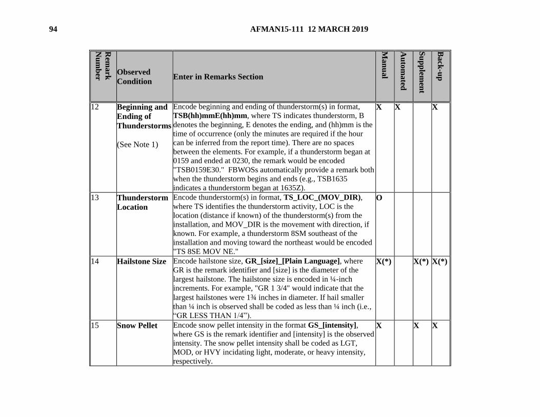
94 AFMAN15-111 12 MARCH 2019
Rem
ark
Nu
mb
er
Observed
Condition Enter in Remarks Section
Man
ual
Au
tom
ated
Su
pp
lemen
t
Back
-up
12 Beginning and
Ending of
Thunderstorms
(See Note 1)
Encode beginning and ending of thunderstorm(s) in format,
TSB(hh)mmE(hh)mm, where TS indicates thunderstorm, B
denotes the beginning, E denotes the ending, and (hh)mm is the
time of occurrence (only the minutes are required if the hour
can be inferred from the report time). There are no spaces
between the elements. For example, if a thunderstorm began at
0159 and ended at 0230, the remark would be encoded
"TSB0159E30." FBWOSs automatically provide a remark both
when the thunderstorm begins and ends (e.g., TSB1635
indicates a thunderstorm began at 1635Z).
X X X
13 Thunderstorm
Location
Encode thunderstorm(s) in format, TS_LOC_(MOV_DIR),
where TS identifies the thunderstorm activity, LOC is the
location (distance if known) of the thunderstorm(s) from the
installation, and MOV_DIR is the movement with direction, if
known. For example, a thunderstorm 8SM southeast of the
installation and moving toward the northeast would be encoded
"TS 8SE MOV NE."
O
14 Hailstone Size Encode hailstone size, GR_[size]_[Plain Language], where
GR is the remark identifier and [size] is the diameter of the
largest hailstone. The hailstone size is encoded in ¼-inch
increments. For example, "GR 1 3/4" would indicate that the
largest hailstones were 1¾ inches in diameter. If hail smaller
than ¼ inch is observed shall be coded as less than ¼ inch (i.e.,
“GR LESS THAN 1/4”).
X(*) X(*)
X(*)
15 Snow Pellet Encode snow pellet intensity in the format GS_[intensity],
where GS is the remark identifier and [intensity] is the observed
intensity. The snow pellet intensity shall be coded as LGT,
MOD, or HVY incidating light, moderate, or heavy intensity,
respectively.
X X X

AFMAN15-111 12 MARCH 2019 95
Rem
ark
Nu
mb
er
Observed
Condition Enter in Remarks Section
Man
ual
Au
tom
ated
Su
pp
lemen
t
Back
-up
16 Variable
Ceiling Height
Encode variable ceiling height (height variable and ceiling layer
below 3000 feet) in format, CIG_hnhnhnVhxhxhx, where CIG is
the remark identifier, hnhnhn is the lowest ceiling height
evaluated, V denotes variability between two values, and
hxhxhx is the highest ceiling height evaluated. There is one
space following the remark identifier; no spaces between the
letter V and the lowest/highest ceiling values. For example,
“CIG 005V010” would indicate a ceiling that was varying
between 500 and 1000 feet.
X X X
17 Partial
Obscurations
Encode partial obscurations (surface-based or aloft) in format,
w'w'_[NsNsNs]hshshs_[Plain Language], where w'w' is the
present weather causing the obscuration at the surface or aloft,
and NsNsNs is the applicable sky cover amount of the
obscuration aloft (FEW, SCT, BKN, OVC) or at the surface
(FEW, SCT, BKN), and hshshs is the applicable height. Surface-
based obscurations will have a height of "000." There is a space
separating the weather causing the obscuration and the sky
cover amount, and no space between the sky cover amount and
the height. For example, fog hiding 3-4 oktas of the sky would
be encoded "FG SCT000." A broken layer of smoke at 2000
feet would be encoded "FU BKN020."
O O
18 Variable Sky
Condition
Encode variable sky condition (sky condition below 3000
feet that varies between one or more reportable values (FEW,
SCT, BKN, OVC) during the period of observation) in
format, NsNsNs(hshshs) _V_NsNsNs_[Plain Language],
where NsNsNs(hshshs) is the predominant sky condition
NsNsNs is the varying sky condition, and V denotes the
variability between the two ranges. For example, SCT V
X X X

96 AFMAN15-111 12 MARCH 2019
Rem
ark
Nu
mb
er
Observed
Condition Enter in Remarks Section
Man
ual
Au
tom
ated
Su
pp
lemen
t
Back
-up
BKN" would identify a scattered layer that is variably
broken. If there are several layers with the same sky
condition amount in the report, the layer height will be coded
with the variable layer. For example, an observation with
cloud layers of SCT010 BKN014 BKN020 with a cloud layer
at 1400 feet that is varying between broken and overcast
would be coded "BKN014 V OVC."
19 Significant
Cloud Types
Encode significant cloud types as follows. Identify
cumulonimbus (CB) of any kind and towering cumulus (TCU)
in the body of the report in the sky condition group. Include
distance if known.
(1) Cumulonimbus or Cumulonimbus Mammatus as
appropriate, (when no thunderstorm is being reported) in format
(CB or CBMAM_LOC_(MOV_DIR)_[Plain Language]
where CB or CBMAM is the cloud type, LOC is the direction
from the observing location, and MOV_DIR is the movement
with direction (if known). Separate the cloud type entries from
each other with a space. For example, a CB 21 nautical miles
west of the observing location moving toward the east would be
encoded "CB 21W MOV E." If a CB is more than 10 nautical
miles to the west and distance cannot be determined, encode as
"CB DSNT W."
(2) Towering cumulus in format TCU_[DIR]_[Plain
Language], where TCU is cloud type and DIR is direction from
the observing location. Separate the cloud type entries by a
space. For example, a towering cumulus cloud up to 10 nautical
O O
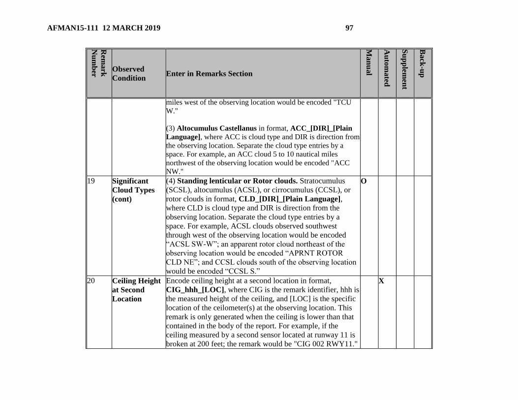
AFMAN15-111 12 MARCH 2019 97
Rem
ark
Nu
mb
er
Observed
Condition Enter in Remarks Section
Man
ual
Au
tom
ated
Su
pp
lemen
t
Back
-up
miles west of the observing location would be encoded "TCU
W."
(3) Altocumulus Castellanus in format, ACC_[DIR]_[Plain
Language], where ACC is cloud type and DIR is direction from
the observing location. Separate the cloud type entries by a
space. For example, an ACC cloud 5 to 10 nautical miles
northwest of the observing location would be encoded "ACC
NW."
19 Significant
Cloud Types
(cont)
(4) Standing lenticular or Rotor clouds. Stratocumulus
(SCSL), altocumulus (ACSL), or cirrocumulus (CCSL), or
rotor clouds in format, CLD_[DIR]_[Plain Language],
where CLD is cloud type and DIR is direction from the
observing location. Separate the cloud type entries by a
space. For example, ACSL clouds observed southwest
through west of the observing location would be encoded
“ACSL SW-W”; an apparent rotor cloud northeast of the
observing location would be encoded “APRNT ROTOR
CLD NE”; and CCSL clouds south of the observing location
would be encoded “CCSL S.”
O
20 Ceiling Height
at Second
Location
Encode ceiling height at a second location in format,
CIG_hhh_[LOC], where CIG is the remark identifier, hhh is
the measured height of the ceiling, and [LOC] is the specific
location of the ceilometer(s) at the observing location. This
remark is only generated when the ceiling is lower than that
contained in the body of the report. For example, if the
ceiling measured by a second sensor located at runway 11 is
broken at 200 feet; the remark would be "CIG 002 RWY11."
X

98 AFMAN15-111 12 MARCH 2019
Rem
ark
Nu
mb
er
Observed
Condition Enter in Remarks Section
Man
ual
Au
tom
ated
Su
pp
lemen
t
Back
-up
21 Pressure Rising
or Falling
Rapidly
Include PRESRR (pressure rising rapidly) or PRESFR
(pressure falling rapidly) when the pressure is rising or
falling at a rate of 0.06 iHg per hour or more, totaling a
change 0.02 iHg or more at the time of observation,
X X X
22 Sea Level
Pressure
Encode sea-level pressure in format SLPppp, where SLP is
the remark identifier and ppp is the sea level pressure in
hectopascals. For example, a sea level pressure of 998.2
hectopascals would be encoded as "SLP982." If SLP is not
available, it is encoded as "SLPNO."
X X X
23 Aircraft
Mishap
Include the remark ACFT_MSHP [Plain Language] to
document weather conditions when notified of an aircraft
mishap. The remark is not transmitted. Indicate non-
transmission by enclosing the remark (ACFT_MSHP) in
parentheses in the observation.
X X X
24 Snow
Increasing
Rapidly
Include the snow increasing rapidly remark in the next
METAR, whenever the snow depth increases by 1 inch or
more in the past hour. Encode the remark in format,
SNINCR_[inches-hour/inches on ground], where SNINCR
is the remark indicator, inches-hour is the depth increase in
the past hour, and inches on ground is the total depth of snow
on the ground at the time of the report. Separate the depth
increase in the past hour from the total depth on the ground
by a slash "/". For example, a snow depth increase of 2
inches in the past hour with a total depth on the ground of 10
inches would be encoded "SNINCR 2/10."
O O

AFMAN15-111 12 MARCH 2019 99
Rem
ark
Nu
mb
er
Observed
Condition Enter in Remarks Section
Man
ual
Au
tom
ated
Su
pp
lemen
t
Back
-up
25 Other
Significant
Information
[Plain
Language
Remarks]
Added to report information significant to aircraft safety or
resource protection. Amplifies entries in main observation.
Some remarks will use the same order of entry as data the
remark most closely relates (e.g., a VIS LWR E remark
would have the entry as a sector visibility remark).
(1) Unofficial Weather Reports. Information important to
local aviation and public safety reported by an individual not
task certified to take official weather observations. For
example, UNOFFL RPT TORNADO 9 W OF KKAC PER
LAW ENFORECMENT or CLD LYR AT 400 FT ON
APCH RWY 23 RPRTD BY PIREPS, CIG VIS LWR ON
APCH RWY14L.
(2) Estimated Wind and Pressure. WND DATA ESTMD
or ALSTG/SLP ESTMD indicates the winds and/or
pressure values from the primary airfield sensors are suspect
or inoperative, and back-up equipment is being used. Report
winds as estimated if using the AN/TMQ-53 as a back-up at
permanent (non-tactical) locations or when the fixed-base
wind equipment on the active end of the runway is
inoperative and the wind data for the runway in use is
obtained using the most reliable system available (e.g.,
inactive runway instrumentation at locations with wind
equipment installed on two or more runways, hand-held
anemometer, Beaufort scale, etc.).
O
X
O
X

100 AFMAN15-111 12 MARCH 2019
Rem
ark
Nu
mb
er
Observed
Condition Enter in Remarks Section
Man
ual
Au
tom
ated
Su
pp
lemen
t
Back
-up
(3) Significant Atmospheric Phenomena not Reported
Elsewhere. Present weather observed but not occurring at the
point of observation or in the vicinity (e.g., SHRA OVR
MTNS N).
(4) Aurora observed in the past hour. Include AURBO in
the next METAR and subsequent METARs throughout
period of occurrence.
(5) Condensation Trails. Include CONTRAILS to indicate
condensation trails are observed.
(6) Location Unique Information (as required), e.g., fog
dispersal, rawinsonde data, state of ground, wind difference
between parallel runways.
O
O
O
O
O
O
O
O
26 Hourly
Precipitation
Amount
(METAR only)
Encode hourly precipitation amount in format, Prrrr, where
P is the group indicator and rrrr is the water equivalent of all
precipitation that has occurred since the last METAR. The
amount is encoded in hundredths of an inch. For example,
"P0009" would indicate 9/100 of an inch of precipitation fell
in the past hour; "P0000" would indicate that less than 1/100
of an inch of precipitation fell in the past hour. When an
indeterminable amount of precipitation has occurred during
the period, encode Prrrr as P////. Omit the group if no
precipitation occurred since the last METAR.
X O
27 3- and 6-Hour
Precipitation
Amount
Encode the 3- and 6-hourly precipitation group in format,
6RRRR, where 6 is the group indicator and RRRR is the
amount of precipitation. Report the amount of precipitation
X X X

AFMAN15-111 12 MARCH 2019 101
Rem
ark
Nu
mb
er
Observed
Condition Enter in Remarks Section
Man
ual
Au
tom
ated
Su
pp
lemen
t
Back
-up
(See Note 2)
(METAR only)
(water equivalent) accumulated in the past 3 hours in the 3-
hourly report; and the amount accumulated in the past 6
hours in the 6-hourly report. The amount of precipitation is
encoded in inches, using the tens, units, tenths and
hundredths digits of the amount. When an indeterminable
amount of precipitation has occurred during the period,
encode RRRR as 6////. For example, 2.17 inches of
precipitation would be encoded "60217." A trace will be
encoded "60000."
28 24-Hour
Precipitation
Amount
(See Note 2)
(METAR only)
Encode the 24-hour precipitation amount in format,
7R24R24R24R24, where 7 is the group indicator and
R24R24R24R24 is the 24-hour precipitation amount. Include the
24-hour precipitation amount in the 1200 UTC (or
MAJCOM/Higher Headquarters designated time) whenever
more than a trace of precipitation (water equivalent) has
fallen in the preceding 24 hours. The amount of precipitation
is encoded by using the tens, units, tenths, and hundredths of
inches (water equivalent) for the 24-hour period. If more than
a trace (water equivalent) has occurred and the amount
cannot be determined, encode the group as 7////. For example,
1.25 inches of precipitation (water equivalent) in the past 24
hours will be encoded "70125."
X X O
29 Snow Depth on
Ground
(See Note 2)
(METAR only)
Encode snow depth during controlled airfield hours in the
0000, 0600, 1200, and 1800 UTC observation, or MAJCOM
specified reporting time for your installation, when
supplementing for snow depth. The remark is encoded in the
format, 4/sss, where 4/ is the group indicator and sss is the
X(*) X O
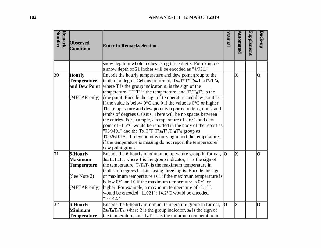
102 AFMAN15-111 12 MARCH 2019
Rem
ark
Nu
mb
er
Observed
Condition Enter in Remarks Section
Man
ual
Au
tom
ated
Su
pp
lemen
t
Back
-up
snow depth in whole inches using three digits. For example,
a snow depth of 21 inches will be encoded as "4/021."
30 Hourly
Temperature
and Dew Point
(METAR only)
Encode the hourly temperature and dew point group to the
tenth of a degree Celsius in format, TsnT’T’T’snT’dT’dT’d,
where T is the group indicator, sn is the sign of the
temperature, T'T'T' is the temperature, and T'dT'dT'd is the
dew point. Encode the sign of temperature and dew point as 1
if the value is below 0°C and 0 if the value is 0°C or higher.
The temperature and dew point is reported in tens, units, and
tenths of degrees Celsius. There will be no spaces between
the entries. For example, a temperature of 2.6°C and dew
point of -1.5°C would be reported in the body of the report as
"03/M01" and the TsnT’T’T’snT’dT’dT’d group as
T00261015". If dew point is missing report the temperature;
if the temperature is missing do not report the temperature/
dew point group.
X O
31 6-Hourly
Maximum
Temperature
(See Note 2)
(METAR only)
Encode the 6-hourly maximum temperature group in format,
1snTxTxTx, where 1 is the group indicator, sn is the sign of
the temperature, TxTxTx is the maximum temperature in
tenths of degrees Celsius using three digits. Encode the sign
of maximum temperature as 1 if the maximum temperature is
below 0°C and 0 if the maximum temperature is 0°C or
higher. For example, a maximum temperature of -2.1°C
would be encoded "11021"; 14.2°C would be encoded
"10142."
O X O
32 6-Hourly
Minimum
Temperature
Encode the 6-hourly minimum temperature group in format,
2snTnTnTn, where 2 is the group indicator, sn is the sign of
the temperature, and TnTnTn is the minimum temperature in
O X O

AFMAN15-111 12 MARCH 2019 103
Rem
ark
Nu
mb
er
Observed
Condition Enter in Remarks Section
Man
ual
Au
tom
ated
Su
pp
lemen
t
Back
-up
(See Note 2)
(METAR only)
tenths of degrees Celsius using three digits. Encode the sign
of minimum temperature as 1 if the minimum temperature is
below 0°C and 0 if the minimum temperature is 0°C or
higher. For example, a minimum temperature of -0.1°C
would be encoded "21001"; 1.2°C would be encoded
"20012."
33 24-Hour
Maximum and
Minimum
Temperature
(METAR only)
Encode the 24-hour maximum temperature and the 24-hour
minimum temperature in format, 4snTxTxTxsnTnTnTn, where
4 is the group indicator, sn is the sign of the temperature,
TxTxTx is the maximum 24-hour temperature, and TnTnTn is
the 24-hour minimum temperature encoded in tenths of
degrees Celsius using three digits. Encode the sign of
maximum or minimum temperature as 1 if it is below 0°C
and 0 if it is 0°C or higher. For example, a 24-hour maximum
temperature of 10.0°C and a 24-hour minimum temperature
of -1.5°C would be encoded "401001015"; a 24-hour
maximum temperature of 11.2°C and a 24-hour minimum
temperature of 8.4°C would be encoded as "401120084."
X O
34 3-Hourly
Pressure
Tendency
(See Note 2)
(METAR only)
Encode the 3-hourly pressure tendency group in format,
5appp, where 5 is the group indicator, "a" is the character of
pressure change over the past 3 hours, and ppp is the amount
of barometric change in tenths of hectopascals. The amount
of barometric change is encoded using the tens, units, and
tenths digits. For example, a steady increase of 3.2
hectopascals in the past three hours would be encoded
"52032." Note: FBWOSs report pressure net change code
figures that Table 13.4 may not reflect, e.g., 001, 004, 006,
011.
O X O

104 AFMAN15-111 12 MARCH 2019
Rem
ark
Nu
mb
er
Observed
Condition Enter in Remarks Section
Man
ual
Au
tom
ated
Su
pp
lemen
t
Back
-up
35 Sensor Status
Indicators
Report sensor outages using the following remarks:
(1) RVRNO - Runway Visual Range information should be
reported but is missing or not available.
(2) PWINO - precipitation identifier information not
available.
(3) PNO - precipitation amount not available.
(4) FZRANO - freezing rain information not available.
(5) TSNO - thunderstorm information not available.
(6) VISNO (LOC) - visibility at secondary location not
available, e.g., VISNO RWY06.
(7) CHINO (LOC) - (cloud-height-indicator) sky condition
at secondary location not available, e.g., CHINO RWY06.
X
X
X
X
X
X
X
X
X
36 Maintenance
Indicator
A maintenance indicator sign $ is appended at the end of the
report when (e.g., FBWOS) maintenance is needed on the
system.
X X
37 (1) LAST (manual
observing
locations only)
(2) FIRST
(1) At limited-duty manual observing locations and gunnery
ranges, identify the last observation of the day (METAR or
SPECI) by adding the term "LAST" following the last
element in the observation text (e.g., TCU SE LAST).
X
X
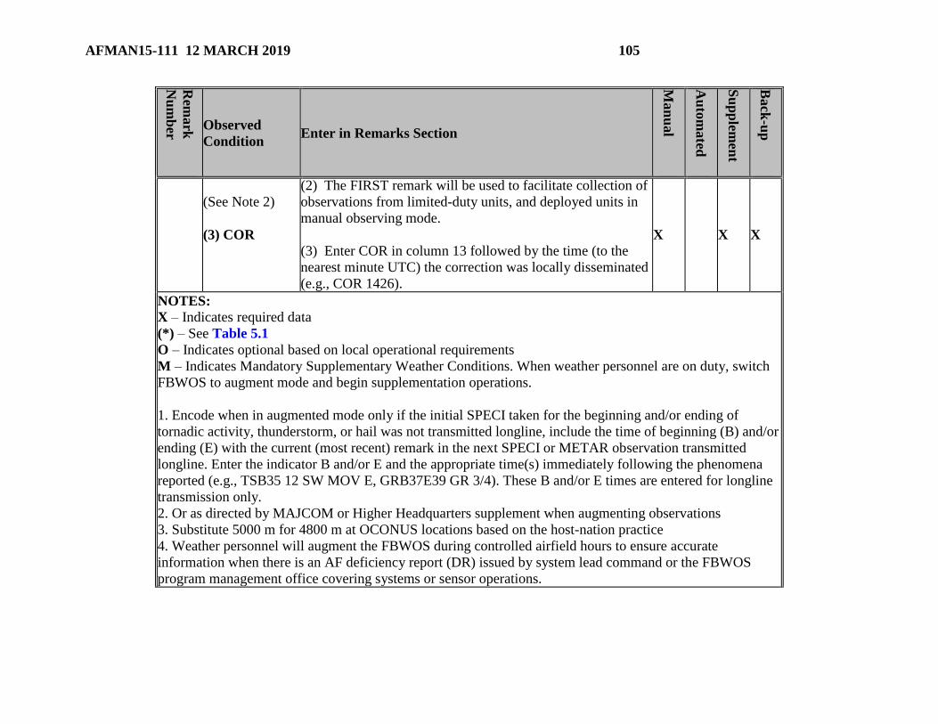
AFMAN15-111 12 MARCH 2019 105
Rem
ark
Nu
mb
er
Observed
Condition Enter in Remarks Section
Man
ual
Au
tom
ated
Su
pp
lemen
t
Back
-up
(See Note 2)
(3) COR
(2) The FIRST remark will be used to facilitate collection of
observations from limited-duty units, and deployed units in
manual observing mode.
(3) Enter COR in column 13 followed by the time (to the
nearest minute UTC) the correction was locally disseminated
(e.g., COR 1426).
X
X
X
NOTES:
X – Indicates required data
(*) – See Table 5.1
O – Indicates optional based on local operational requirements
M – Indicates Mandatory Supplementary Weather Conditions. When weather personnel are on duty, switch
FBWOS to augment mode and begin supplementation operations.
1. Encode when in augmented mode only if the initial SPECI taken for the beginning and/or ending of
tornadic activity, thunderstorm, or hail was not transmitted longline, include the time of beginning (B) and/or
ending (E) with the current (most recent) remark in the next SPECI or METAR observation transmitted
longline. Enter the indicator B and/or E and the appropriate time(s) immediately following the phenomena
reported (e.g., TSB35 12 SW MOV E, GRB37E39 GR 3/4). These B and/or E times are entered for longline
transmission only.
2. Or as directed by MAJCOM or Higher Headquarters supplement when augmenting observations
3. Substitute 5000 m for 4800 m at OCONUS locations based on the host-nation practice
4. Weather personnel will augment the FBWOS during controlled airfield hours to ensure accurate
information when there is an AF deficiency report (DR) issued by system lead command or the FBWOS
program management office covering systems or sensor operations.

Attachment 4
STATION INFORMATION
Figure A4.1. Required Information in the Station Information File.
STATION INFORMATION FILE
Physical Characteristics - Name of Installation.
- Station ICAO Identifier.
- WMO Index Number.
- Time Zone (+/- relative to UTC).
- Latitude/Longitude to the nearest minute
- Field Elevation.
- Station Elevation (or elevation of FBWOS, primary
group).
- Elevation of Primary Barometer (or elevation of
FBWOS, primary group).
Observing Operation (consistent
with FLIP entires)
- Full automated operations (provide operating hours).
- Augmented observations (provide hours observations
are available).
Sensor Data - FBWOS. Date installed and commissioned.
- Location of FBWOS sensors in relation to the airfield
runways.
- Legacy Fixed-Base Sensors (list all).
- Location of legacy sensors in relation to the airfield
runways.
- Explain any non-standard siting of sensors.
- Provide listing of FBWOS back-up equipment.
Physical Description of
Observation Site.
Include additional features that affect the weather or
climatology. For example, surrounding surface grass,
dirt, concrete, asphalt, nearby bodies of water,
trees/forest, etc. Include available maps, layouts, photos,
etc.