
AIR FLOW IN DUCTS Shaharin Anwar Sulaiman Now that you can size equipment, the next task would be to...
22
AIR FLOW IN DUCTS AIR FLOW IN DUCTS Shaharin Anwar Sulaiman Now that you can size equipment, the next task would be to design the Now that you can size equipment, the next task would be to design the air distribution system. air distribution system.
-
Upload
austin-richards -
Category
Documents
-
view
215 -
download
0
Transcript of AIR FLOW IN DUCTS Shaharin Anwar Sulaiman Now that you can size equipment, the next task would be to...

AIR FLOW IN DUCTSAIR FLOW IN DUCTS
Shaharin Anwar Sulaiman
Now that you can size equipment, the next task would be to design the air distribution system.Now that you can size equipment, the next task would be to design the air distribution system.

Duct design objectives
• Occupant comfort• Proper air distribution• Economical heating and cooling system operation• Economical duct installation

Supply duct systems
• Supply ducts deliver air to the spaces that are to be conditioned. • The two most common supply duct systems for residences are:• The trunk and branch system and The radial system

SUPPLY DUCT CONFIGURATIONS

ContentContent
Friction losses in:Friction losses in:• round ducts round ducts • rectangular ducts (aspect ratio)rectangular ducts (aspect ratio)• inlet / outlet of fansinlet / outlet of fans• fittingsfittings
Duct sizing methods:Duct sizing methods:• Equal Friction MethodEqual Friction Method• Static Regain MethodStatic Regain Method

FRICTION LOSSES FROM AIRFRICTION LOSSES FROM AIRFLOW IN DUCTSFLOW IN DUCTS
Like piping, for convenience pressure Like piping, for convenience pressure loss due to friction for air flow is loss due to friction for air flow is available in a chart (Fig. 8.21).available in a chart (Fig. 8.21).
Chart is however meant for straight Chart is however meant for straight round duct.round duct.
The chart assumes clean galvanised The chart assumes clean galvanised steel material with about 40 joints per steel material with about 40 joints per 100 ft, with air at standard conditions.100 ft, with air at standard conditions.

See Fig. 8.21See Fig. 8.21
It’s quite similar to It’s quite similar to Fig. 8.13, 8.14, 8.15 Fig. 8.13, 8.14, 8.15
used for pipingused for piping
FRICTION LOSSES FROM AIRFRICTION LOSSES FROM AIRFLOW IN DUCTSFLOW IN DUCTS
EQUIVALENT EQUIVALENT ROUND ROUND
DUCT SIZESDUCT SIZES
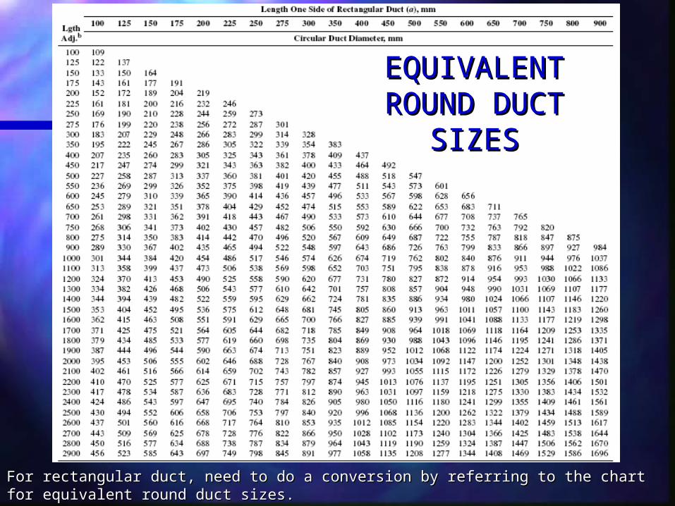
For rectangular duct, need to do a conversion by referring to the chart for equivalent round duct For rectangular duct, need to do a conversion by referring to the chart for equivalent round duct sizes.sizes.

EQUIVALENT EQUIVALENT ROUND ROUND
DUCT SIZESDUCT SIZES
For rectangular duct, For rectangular duct, need to do a conversion need to do a conversion by referring to the chart by referring to the chart for equivalent round for equivalent round duct sizes.duct sizes.
Can also use ductulator.Can also use ductulator.

FRICTION LOSSES FROM AIRFRICTION LOSSES FROM AIRFLOW IN DUCTSFLOW IN DUCTS
Example-1:Example-1:
A 10” diameter round galvanised duct 200’ long has A 10” diameter round galvanised duct 200’ long has 150 cfm of air flowing through it. What is the pressure 150 cfm of air flowing through it. What is the pressure loss due to friction? What is the air velocity in the loss due to friction? What is the air velocity in the duct?duct?
Refer to Fig. 8.21:Refer to Fig. 8.21:At 150 cfm and 10 in diameter, the friction loss is 0.015 At 150 cfm and 10 in diameter, the friction loss is 0.015 ft. w per 100 feet. Therefore for 200 ft pipe:ft. w per 100 feet. Therefore for 200 ft pipe:
HHff = 0.015/100’ x 200’ = 0.03 ft.w = 0.015/100’ x 200’ = 0.03 ft.w
Velocity = ?Velocity = ?
FRICTION LOSSES FROM AIRFRICTION LOSSES FROM AIRFLOW IN DUCTSFLOW IN DUCTS
Example-2:Example-2:
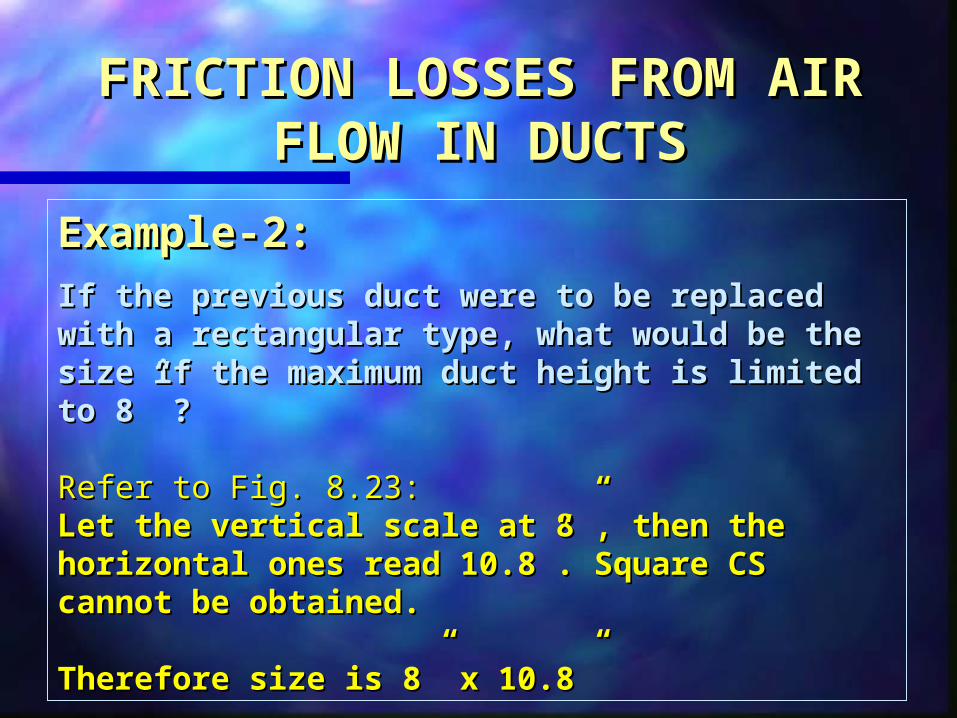
If the previous duct were to be replaced with a If the previous duct were to be replaced with a rectangular type, what would be the size if the rectangular type, what would be the size if the maximum duct height is limited to 8” ? maximum duct height is limited to 8” ?
Refer to Fig. 8.23:Refer to Fig. 8.23:Let the vertical scale at 8”, then the horizontal ones Let the vertical scale at 8”, then the horizontal ones read 10.8”. Square CS cannot be obtained.read 10.8”. Square CS cannot be obtained.
Therefore size is 8” x 10.8”Therefore size is 8” x 10.8”


It may be thought that equivalent round duct will have the same cross-sectional area as the rectangular duct for the same friction loss.
However, actually for same friction loss, rectangular duct will have greater cross-sectional area.
ASPECT RATIOASPECT RATIO
Because of the rectangle shape that has greater ratio of surface to cross-section, the flow experiences more friction.
This is related to Aspect Ratio (AR).
Aspect Ratio (AR) is the ratio of the two adjacent sides - height over width or vice versa.

ASPECT RATIOASPECT RATIO
Higher AR also means more material for ducting.
The best option is to have square duct.
But that is not always possible due to limited ceiling space.
The higher the aspect ratio, the worse the friction loss.
As a general rule, the AR of rectangular ducts should be kept as low as possible to minimise friction losses and save energy.

DUCT FITTINGSDUCT FITTINGS
Like in pipes, pressure loss also occurs Like in pipes, pressure loss also occurs in duct fittings.in duct fittings.
Duct fittings could be elbow, tee, Duct fittings could be elbow, tee, transition, and dampers.transition, and dampers.
Similar to piping system, the equivalent Similar to piping system, the equivalent length could be used.length could be used.
Another option is the use of Another option is the use of loss loss coefficient method.coefficient method.

DUCT FITTINGSDUCT FITTINGS
For loss coefficient method, the For loss coefficient method, the following equation is used:following equation is used:
The values for loss coefficients can be The values for loss coefficients can be found in Table 8.4 - 8.8.found in Table 8.4 - 8.8.
2
4000
V
CHCH vf

DUCT FITTINGSDUCT FITTINGS
Example 8.22 & 8.23:Example 8.22 & 8.23:own readingown reading
Notice that answers are not accurately Notice that answers are not accurately written. Hwritten. Hff = 0.035 in both examples. = 0.035 in both examples.

DUCT FITTINGSDUCT FITTINGS
Example 8.23Example 8.23also shows the SPRalso shows the SPR
(Static pressure regain)(Static pressure regain)
SPR: When velocity decrease, due to change in SPR: When velocity decrease, due to change in ducting size, there will be an increase in the ducting size, there will be an increase in the static pressurestatic pressure

PRESSURE LOSS AT PRESSURE LOSS AT FAN INLET & OUTLETFAN INLET & OUTLET
System Effect Loss.
Own reading(Sec. 8.14)

DUCT SYSTEM PRESSURE LOSSDUCT SYSTEM PRESSURE LOSS
In piping system, the pressure loss In piping system, the pressure loss must be calculated to properly size must be calculated to properly size the pump.the pump.
Likewise, in duct, the duct pressure Likewise, in duct, the duct pressure losses must be determined to losses must be determined to identify the proper fan capacity.identify the proper fan capacity.

DUCT SYSTEM PRESSURE LOSSDUCT SYSTEM PRESSURE LOSS
System total pressure lossSystem total pressure loss
the total pressure loss through the total pressure loss through the duct path that has the the duct path that has the largest pressure losses.largest pressure losses.
Fan
700cfm 300 cfm
500 cfm

DUCT SYSTEM PRESSURE LOSSDUCT SYSTEM PRESSURE LOSS
In analysing duct pressure losses, total pressure In analysing duct pressure losses, total pressure loss is preferred to static pressure loss. loss is preferred to static pressure loss.
It gives clearer picture of the total pressure It gives clearer picture of the total pressure available at any point in the duct.available at any point in the duct.
Identification of total pressure loss is quite similar Identification of total pressure loss is quite similar to the piping system (fluid mechs); i.e. everything to the piping system (fluid mechs); i.e. everything must be included, including the filter.must be included, including the filter.
Go through examples 8.25 & 8.26.Go through examples 8.25 & 8.26.