AhklikAs strong as the weakest link
15
IEEE Santa Clara Valley CPMT Chapter February 8, 2012 www.cpmt.org/scv 1 A h k li k As strong as the weak est link: Reliability from the LED system ti perspective Rudi Hechfellner, Dir. Of Applications, Philips Lumileds Mark Hodapp, Senior Application Engineer, Philips Lumileds Design for reliability Agenda Long term LED reliability (f LED f t it f i ) – Long term LED reliability (from a LED manufacturers point of view) • lumen maintenance, wear-out failure probability and long term color stability – Methods of scaling single LED behavior to a system with multiple LEDs – The impact of LED behavior on a luminaires light output performance – Best known practices for designing reliable lighting sub-systems Notice LEDs from different manufacturers will have different reliability profiles – Different material systems – Different manufacturing methods etc.
Transcript of AhklikAs strong as the weakest link

IEEE Santa Clara Valley CPMT Chapter February 8, 2012
www.cpmt.org/scv 1
A h k li kAs strong as the weakest link:
Reliability from the LED system tiperspective
Rudi Hechfellner, Dir. Of Applications, Philips LumiledsMark Hodapp, Senior Application Engineer, Philips Lumileds
Design for reliability
AgendaLong term LED reliability (f LED f t i t f i )– Long term LED reliability (from a LED manufacturers point of view)
• lumen maintenance, wear-out failure probability and long term color stability
– Methods of scaling single LED behavior to a system with multiple LEDs
– The impact of LED behavior on a luminaires light output performance
– Best known practices for designing reliable lighting sub-systems
NoticeLEDs from different manufacturers will have different reliability profiles
– Different material systems
– Different manufacturing methods etc.

IEEE Santa Clara Valley CPMT Chapter February 8, 2012
www.cpmt.org/scv 2
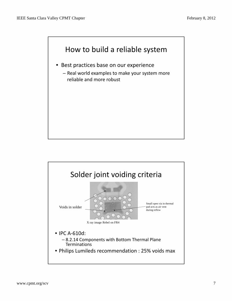
System Reliability ≠ LED Reliability
Rsystem = Relectrical * Rconnections * RLEDs * Roptical * Rthermal * Rmechanical
Reliability – Influencing Factors
LED design- Electrical parameters
Heat transport
Customer application- Heat transport
PCB layout and material
SystemReliability
- Heat transport- ESD layout- Package
AssemblySt diti
- PCB layout and material- ESD protection- Electrical circuit
EnvironmentAmbient temperature- Storage condition
- Soldering process- Handling (pick & place;ESD)
- Ambient temperature- Temperature cycles- Humidity- Pollution- Light radiation
Source: OSRAM OS Application Note Reliability and Lifetime July ‘08

IEEE Santa Clara Valley CPMT Chapter February 8, 2012
www.cpmt.org/scv 3
Chronological progression of system failure rate
Source: OSRAM OS Application Note Reliability and Lifetime July ‘08
Design for Reliability Workshop, October 25, 2010
LED Reliability
Power LED Power LED Power LED ReliabilityReliabilityReliability
Lumen Maintenance Wear-out behaviorWear-out behavior Color stabilityColor stabilityWear-out behavior Color stabilityMaintenance WW C yC yW C y
Design for Reliability Workshop, October 25, 2010

IEEE Santa Clara Valley CPMT Chapter February 8, 2012
www.cpmt.org/scv 4
Lumen Maintenance
Not all LEDs behave the same way!
Cool-White LUXEON Rebel stressed at 85°C, 0.35A (Tjunction 98°C)
Normalized to 1 at 24 hours1.2
b0.7ln
L70
a = -2.2816e-6b = 1.0054
*Philips Lumileds recommends extrapolations
Data collection following IESNA LM-80
Data projection following IESNA TM21
For LUXEON Rebel
• Drive current and Junction Temperature affect lumen maintenance.
• Ambient Temperature TA has no confirmed impact on lumen maintenance 0 7
0.8
0.9
1.0
1.1
No
rma
lized
Lig
ht
Ou
tpu
t
Extrapolated Data = -1.7% at 10,000 hours
ENERGY STAR 35,000 and 25,000 hour limitsafter 6,000 hours of stress
aL70
35,000 hour25,000 hour
6x test time*
of 6x the test time
maintenance.
0.6
0.7
1,000 10,000 100,000 1,000,000
Hours
Ta within -5C of Ts, in accordance with LM80.Sample size = 78 units, y-axis error bar = +/- 3 standard d i ti
L70 = 159,000 hours
End of Life Failure Analysis
• LED End of Life failure rates can be modeled using the same general principles as silicon-based semiconductors
Catastrophic failure rates LUXEON Rebel using TFFC
1
End of life behavior
semiconductors.
– Failure rate versus operating time can be determined for several different stress conditions [i.e. different combinations of TJ and IF].
• By design, white LUXEON Rebel LEDs fail short. 0.001
0.01
0.1
Pro
bab
ilit
y o
f F
ailu
re
Temperature1
Temperature2
Temperature3
Temperature1 > Temperature2 > Temperature3
0.0001
100 1,000 10,000 100,000 1,000,000
Hours
Curves are 90% LCL worst case. Curve shifts to the left at higher temperatures.

IEEE Santa Clara Valley CPMT Chapter February 8, 2012
www.cpmt.org/scv 5
LED Reliability
SystemReliability
Lumen Maintenance Failures
Wear-Out Failures
Drive Current
Junction Temp
End of Life Rate&Confidence Interval
Temp.
1.0
1.2
nan
ce
LED Lumen Maintenance versus Time (not to scale)
0.4
0.6
0.8
mp
on
ent
Lu
men
Mai
nte
n
LED1
LED2
LED3
LED4
LED5
0.0
0.2
LE
D C
om
Hours of Operation
IEEE Santa Clara Valley CPMT Chapter February 8, 2012
www.cpmt.org/scv 6
1.0
1.2LED1
LED2
LED3
LED4
LED5e
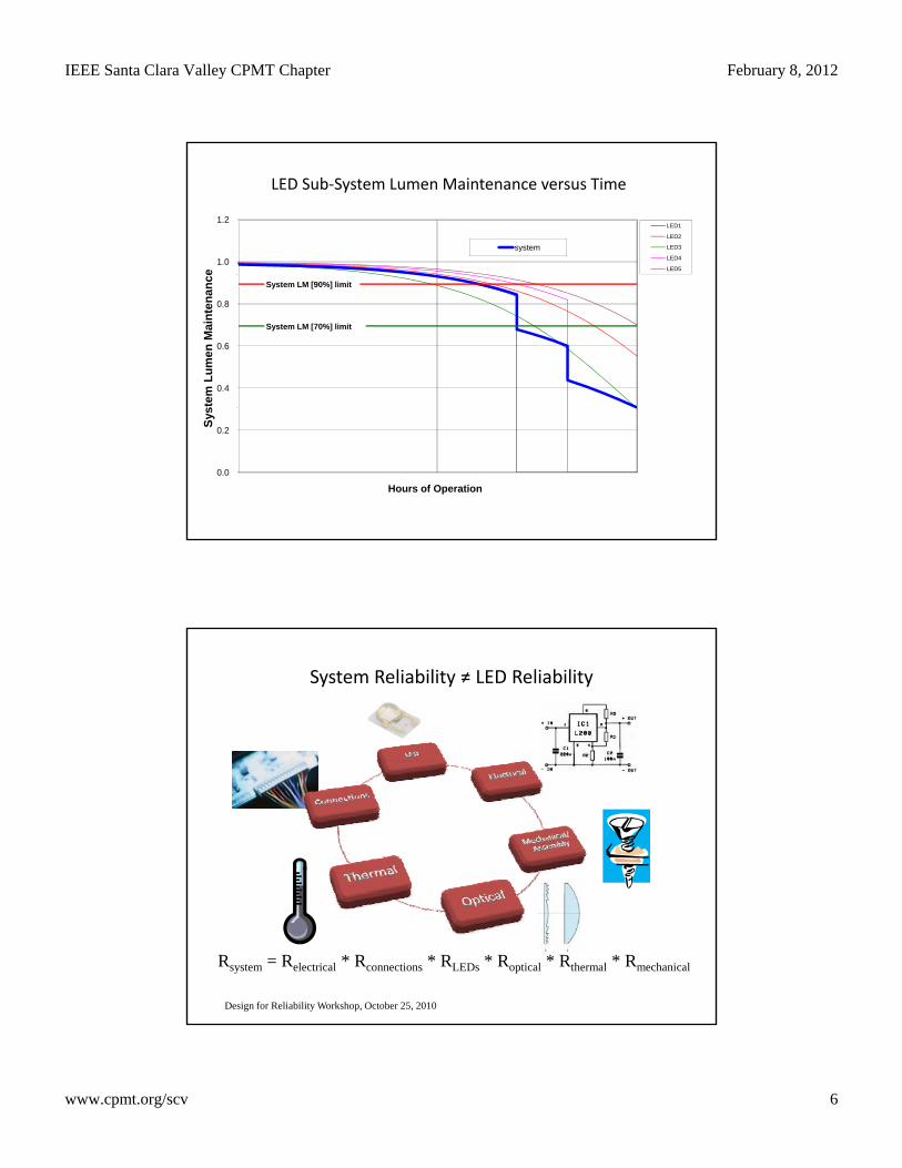
LED Sub-System Lumen Maintenance versus Time
system
0.4
0.6
0.8
stem
Lu
men
Mai
nte
nan
ce
System LM [90%] limit
System LM [70%] limit
0.0
0.2
Hours of Operation
Sys
System Reliability ≠ LED Reliability
Rsystem = Relectrical * Rconnections * RLEDs * Roptical * Rthermal * Rmechanical
Design for Reliability Workshop, October 25, 2010
IEEE Santa Clara Valley CPMT Chapter February 8, 2012
www.cpmt.org/scv 7
How to build a reliable system
• Best practices base on our experience
– Real world examples to make your system more reliable and more robust
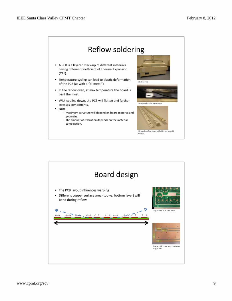
Solder joint voiding criteria
Voids in solder
X ray image Rebel on FR4
Small open via in thermal pad acts as air vent during reflow
• IPC A-610d:– 8.2.14 Components with Bottom Thermal Plane
Terminations
• Philips Lumileds recommendation : 25% voids max

IEEE Santa Clara Valley CPMT Chapter February 8, 2012
www.cpmt.org/scv 8
LUXEON Rebel solder voids
• Influence of voids on thermal resistance
• LUXEON Rebel examples
– Voids % has no impact on thermal resistance
8
9
10
11
ion
to
hea
tsin
k) (
K/W
)
50 micron solder joint
100 micron solder joint
Voids: ~20%
7
8
0% 10% 20% 30% 40% 50% 60% 70% 80% 90% 100%percentage of voids in solder joint
Rth
(ju
nct
Voids : 0%Measured Rth values shows no significant difference versus voiding %
Process steps with risk of mechanical stress
• ReflowW i d i h t l ( t i l)– Warping during heat cycles (material)
• Separating the PCB from the panel – V-cut – Breaking
• Final assemblyMounting warped PCB– Mounting warped PCB
– Uneven force distribution for fixing PCB• Positioning of screws
IEEE Santa Clara Valley CPMT Chapter February 8, 2012
www.cpmt.org/scv 9
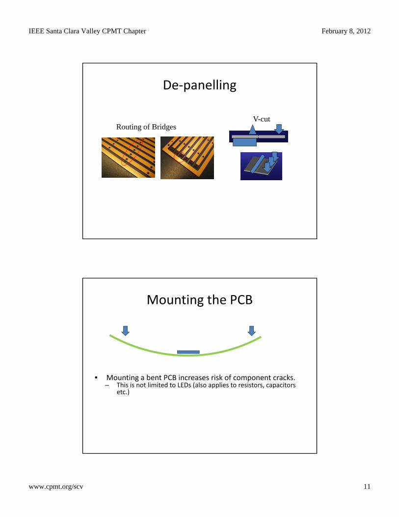
Reflow soldering
• A PCB is a layered stack-up of different materials having different Coefficient of Thermal Expansion g p(CTE).
• Temperature cycling can lead to elastic deformation of the PCB (as with a “bi-metal”)
• In the reflow oven, at max temperature the board is bent the most.
• With cooling down, the PCB will flatten and further stresses components
Reflow oven
Bent boards in the reflow ovenstresses components.
• Note– Maximum curvature will depend on board material and
geometry.– The amount of relaxation depends on the material
combination.
Relaxation of the board will differ per material choices.
Board design
• The PCB layout influences warping
• Different copper surface area (top vs bottom layer) willDifferent copper surface area (top vs. bottom layer) will bend during reflow
Top side of PCB with traces
Bottom side - one large continuous copper area

IEEE Santa Clara Valley CPMT Chapter February 8, 2012
www.cpmt.org/scv 10
Board design
• Equal copper areas on top and bottom side balance forces B d ’t b d– Board won’t bend
Back side copper islands
Separation of boards
• Separation of the board from the panel has to be done with care
Strip 1
Strip 2
• Bending in long direction of the PCB
• Twisted in short direction
of the PCB
IEEE Santa Clara Valley CPMT Chapter February 8, 2012
www.cpmt.org/scv 11
De-panelling
V-cutRouting of Bridges
V cu
Mounting the PCB
• Mounting a bent PCB increases risk of component cracks.– This is not limited to LEDs (also applies to resistors, capacitors
etc.))

IEEE Santa Clara Valley CPMT Chapter February 8, 2012
www.cpmt.org/scv 12
Screw positions for board assembly
• Thermal Interface Material (TIM) is often used between board and heat sink
BoardTIMHeat sink
(for defined thermal contact)– If the holes are positioned on the edges
of the board the TIM will be pressed together and the board will bend, especially for thick, soft TIM (A).
– If the holes are positioned more to the center the forces will be distributed more equally and the bending of themore equally and the bending of the board is less (B). See also next slide.
PCB screw positions experiment
• PCB test boards with different screw positions.
Af bl d l f h PCB h• After assembly and removal of the PCB the contact areas of the TIM are visible.
• For larger distances between the holes the center area did not make contact, the PCB is bent and doesn’t have solid thermal contact.
TIM material 1
TIM material 2

IEEE Santa Clara Valley CPMT Chapter February 8, 2012
www.cpmt.org/scv 13
Secondary optics materials
Transparent materials evaluated
• PMMA (Polymethyl methacrylate)• PMMA (Polymethyl methacrylate)
• PMMI (Polymethylmethacrylimide)
• PC (Polycarbonate)
• PA (Polyamide)
• COP (Cyclic Olefin Polymers)
PMMA / Lucite PMMI / EvonikPC / DSMPMMA / Lucite PMMI / EvonikPC / DSM
• COC (Cyclic Olefin Copolymer)
COC / TopasPA / EMS COP / ZEON COC / TopasPA / EMS COP / ZEON
Important material parameters• For transparent materials the most important parameters are:
M i i– Maximum operating temperature– Can this material be used in this application?
– Brittleness– Important for screw holes or click fingers
– Optical transmission (over time)– Can have influence on the Lumen Maintenance of the application
– Refractive Index– key optical design parameter
– Material cost
– Moldability– Quality, process time, accuracy

IEEE Santa Clara Valley CPMT Chapter February 8, 2012
www.cpmt.org/scv 14
Sample overview transparent materials
PAPMMA PMMI PCCOC COP
Best choices for secondary optics materials
• PMMA gives the best overall performance for i td li ti h thuse in outdoor application where the
maximum operating temperature is below 85°C.
– Based on lens quality (molding process), UV resistance, cost, and molder selection.
• PMMI gives the best overall performance where the maximum operating temperature is above 85°C.

IEEE Santa Clara Valley CPMT Chapter February 8, 2012
www.cpmt.org/scv 15
Board Assembly - Pick and Place
• Nozzle Choice
• Special Feeders
Conclusion
• Simulations around the LED Sub-system are useful to determine system reliabilityuseful to determine system reliability– One step further than relying simply on an LM-80
test report
• LED Sub-system integration is important– Mounting, assembly and component placement
etcetc.
• Understanding this can have a significant impact on the sustainability of the business