
Finite Element Static,Dynamic and Stability Analyses of Arbitary Stiffened Plates - jan Barik
Agilent
Arbitrary Waveform
Generator
M8190A
User’s Guide
Notices
© Agilent Technologies, Inc. 2012
No part of this manual may be reproduced in any
form or by any means (including electronic
storage and retrieval or translation into a foreign
language) without prior agreement and written
consent from Agilent Technologies, Inc. as
governed by United States and international
copyright laws.
Manual Part Number
M8190-91030
Edition
Third edition, July 2012
Agilent Technologies, Deutschland GmbH
Herrenberger Str. 130
71034 Böblingen, Germany
For Assistance and Support
Limitation of Warranty
The foregoing warranty shall not apply to defects
resulting from improper or inadequate
maintenance by Buyer, Buyer-supplied software or
interfacing, unauthorized modification or misuse,
operation outside of the environmental
specifications for the product, or improper site
preparation or maintenance. No other warranty is
expressed or implied. Agilent Technologies
specifically disclaims the implied warranties of
Merchantability and Fitness for a Particular
Purpose.
Warranty
The material contained in this document is
provided “as is,” and is subject to being
changed, without notice, in future editions.
Further, to the maximum extent permitted by
applicable law, Agilent disclaims all warranties,
either express or implied, with regard to this
manual and any information contained herein,
including but not limited to the implied
warranties of merchantability and fitness for a
particular purpose. Agilent shall not be liable for
errors or for incidental or consequential
damages in connection with the furnishing, use,
or performance of this document or of any
information contained herein. Should Agilent and
the user have a separate written agreement with
warranty terms covering the material in this
document that conflict with these terms, the
warranty terms in the separate agreement shall
control.
Technology Licenses
The hardware and/or software described in this
document are furnished under a license and may
be used or copied only in accordance with the
terms of such license.
Restricted Rights Legend
If software is for use in the performance of a U.S.
Government prime contract or subcontract,
Software is delivered and licensed as
“Commercial computer software” as defined in
DFAR 252.227-7014 (June 1995), or as a
“commercial item” as defined in FAR 2.101(a) or
as “Restricted computer software” as defined in
FAR 52.227-19 (June 1987) or any equivalent
agency regulation or contract clause. Use,
duplication or disclosure of Software is subject to
Agilent Technologies’ standard commercial
license terms, and non-DOD Departments and
Agencies of the U.S. Government will receive no
greater than Restricted Rights as defined in FAR
52.227-19(c)(1-2) (June 1987). U.S. Government
users will receive no greater than Limited Rights
as defined in FAR 52.227-14 (June 1987) or DFAR
252.227-7015 (b)(2) (November 1995), as
applicable in any technical data.
ESD sensitive device
All front-panel connectors of the M8190A are
sensitive to Electrostatic discharge (ESD).
We recommend to operate the instrument in an
electrostatic safe environment.
There is a risk of instrument malfunction when
touching a connector.
Please follow this instruction:
Before touching the front-panel connectors
discharge yourself by touching the properly
grounded mainframe.
Safety Notices
A CAUTION notice denotes a hazard. It
calls attention to an operating
procedure, practice, or the like that, if
not correctly performed or adhered to,
could result in damage to the product
or loss of important data. Do not
proceed beyond a CAUTION notice until
the indicated conditions are fully
understood and met.
A WARNING notice denotes a hazard.
It calls attention to an operating
procedure, practice, or the like that, if
not correctly performed or adhered to,
could result in personal injury or
death. Do not proceed beyond a
WARNING notice until the indicated
conditions are fully understood and
met.
CAUTION
WARNING

The following general safety precautions
must be observed during all phases of
operation of this instrument. Failure to
comply with these precautions or with
specific warnings elsewhere in this manual
violates safety standards of design,
manufacture, and intended use of the
instrument.
For safe operation the general safety
precautions for the M9502A and M9505A
AXIe chassis, must be followed. See:
http://www.agilent.com/find/M9505A
Agilent Technologies Inc. assumes no
liability for the customer's failure to comply
with these requirements.
Before operation, review the instrument and
manual for safety markings and instructions.
You must follow these to ensure safe
operation and to maintain the instrument in
safe condition.
Inspect the shipping container for damage. If
there is damage to the container or
cushioning, keep them until you have
checked the contents of the shipment for
completeness and verified the instrument
both mechanically and electrically. The
Performance Tests give procedures for
checking the operation of the instrument. If
the contents are incomplete, mechanical
damage or defect is apparent, or if an
instrument does not pass the operator’s
checks, notify the nearest Agilent
Technologies Sales/Service Office.
WARNING To avoid hazardous electrical
shock, do not perform electrical tests when
there are signs of shipping damage to any
portion of the outer enclosure (covers,
panels, etc.).
This product is a Safety Class 3 instrument.
The protective features of this product may
be impaired if it is used in a manner not
specified in the operation instructions.
This instrument is intended for indoor use
in an installation category II, pollution
degree 2 environment. It is designed to
operate within a temperature range of
0 °C – 40 °C (32 °F – 105 °F) at a
maximum relative humidity of 80% and at
altitudes of up to 2000 meters.
This module can be stored or shipped at
temperatures between -40 °C and +70 °C.
Protect the module from temperature
extremes that may cause condensation
within it.
Verify that all safety precautions are taken
including those defined for the mainframe.
The Agilent M8190A operates when
installed in an Agilent AXIe mainframe.
Do not operate the instrument in the
presence of flammable gases or fumes.
Operating personnel must not remove
instrument covers. Component replacement
and internal adjustments must be made only
by qualified personnel.
Instruments that appear damaged or
defective should be made inoperative and
secured against unintended operation until
they can be repaired by qualified service
personnel.
4
Indicates warning or caution. If you see this
symbol on a product, you must refer to the
manuals for specific Warning or Caution
information to avoid personal injury or damage to
the product.
C-Tick Conformity Mark of the Australian ACA for
EMC compliance.
CE Marking to state compliance within the
European Community: This product is in
conformity with the relevant European Directives.
General Recycling Mark
This product complies with the WEEE Directive
(2002/96/EC) marketing requirements. The affixed
label indicates that you must not discard this
electrical/electronic product in domestic household
waste.
Product category: With reference to the equipment
types in the WEEE Directive Annexure I, this product
is classed as a “Monitoring and Control
instrumentation” product.
Do not dispose in domestic household waste.
To return unwanted products, contact your local
Agilent office, or see
www.agilent.com/environment/product/ for more
information.
Contents
M8190A User’s Guide 5
Contents
Contents ................................................................................................................................................................... 5
1 Introduction ............................................................................................................................................. 13
1.1 Document History ............................................................................................................................14
1.2 Hardware Revisions .........................................................................................................................14
1.3 Options ...............................................................................................................................................16
1.4 The Front Panel of the Two Channel Instrument .......................................................................18
1.5 The Front Panel of the One Channel Instrument ........................................................................20
1.6 Modes of Operation .........................................................................................................................21
1.6.1 Block Diagram .......................................................................................................................... 21
1.6.2 NRZ / DNRZ / Doublet ........................................................................................................... 23
1.6.3 Delay Adjust .............................................................................................................................. 26
1.7 Installing Licenses ...........................................................................................................................27
2 M8190A User Interface .......................................................................................................................... 29
2.1 Introduction .......................................................................................................................................29
2.2 Launching the M8190A Soft Front Panel .....................................................................................29
2.3 M8190A User Interface Overview .................................................................................................32
2.3.1 Title Bar ..................................................................................................................................... 32
2.3.2 Menu Bar ................................................................................................................................... 32
2.3.3 Status Bar.................................................................................................................................. 35
2.3.4 Clock/Output/Aux/Status/Control Tabs ............................................................................ 35
2.3.5 Numeric Control Usage ........................................................................................................... 35
2.4 Driver Call Log ..................................................................................................................................37
2.5 Errors Window ..................................................................................................................................38
2.6 Waveform File Import Dialog .........................................................................................................39
2.7 Clock Tab ...........................................................................................................................................40
2.8 Output Tab .........................................................................................................................................42
2.9 Aux Tab ..............................................................................................................................................44
2.10 Status/Control Tab ..........................................................................................................................46
6
3 Sequencing .............................................................................................................................................. 49
3.1 Introduction .......................................................................................................................................49
3.1.1 Option Sequencing .................................................................................................................. 49
3.1.2 Sequence Table ........................................................................................................................ 49
3.1.3 Sequencer Granularity ............................................................................................................ 50
3.2 Sequencing Hierarchy .....................................................................................................................51
3.2.1 Segment ..................................................................................................................................... 51
3.2.2 Sequence ................................................................................................................................... 51
3.2.3 Scenario ..................................................................................................................................... 52
3.3 Trigger Modes ..................................................................................................................................52
3.3.1 Auto ............................................................................................................................................ 52
3.3.2 Triggered.................................................................................................................................... 52
3.3.3 Gated .......................................................................................................................................... 53
3.4 Arm Mode .........................................................................................................................................53
3.4.1 Self Armed ................................................................................................................................. 53
3.4.2 Armed ......................................................................................................................................... 53
3.5 Advancement Modes ......................................................................................................................54
3.5.1 Auto ............................................................................................................................................ 54
3.5.2 Conditional ................................................................................................................................ 54
3.5.3 Repeated .................................................................................................................................... 54
3.5.4 Single ......................................................................................................................................... 55
3.6 Sequencer Controls .........................................................................................................................55
3.6.1 External Inputs ......................................................................................................................... 55
3.6.2 Logical Functions ..................................................................................................................... 60
3.6.3 Internal Trigger Generator ...................................................................................................... 61
3.6.4 Mapping External Inputs to Logical Functions ................................................................... 61
3.7 Sequencer Execution Flow .............................................................................................................64
3.8 Sequencer Modes ............................................................................................................................65
3.8.1 Arbitrary Mode ......................................................................................................................... 65
3.8.2 Sequence Mode ....................................................................................................................... 70
3.8.3 Scenario Mode ......................................................................................................................... 77
3.9 Dynamic Sequencing .......................................................................................................................81
3.9.1 Dynamic Continuous ............................................................................................................... 82
3.9.2 Dynamic Triggered ................................................................................................................... 83
3.10 Markers ..............................................................................................................................................84
3.10.1 High Speed Markers ................................................................................................................ 84
Contents
M8190A User’s Guide 7
3.10.2 Sync Markers ............................................................................................................................ 85
3.11 Idle Command Segments ................................................................................................................86
3.12 Limitations .........................................................................................................................................87
3.12.1 Segment Length and Linear Playtime .................................................................................. 87
4 General Programming ............................................................................................................................ 91
4.1 Introduction .......................................................................................................................................91
4.2 IVI-COM Programming ....................................................................................................................92
4.3 SCPI Programming ...........................................................................................................................93
4.3.1 AgM8190Firmware.exe ........................................................................................................... 93
4.4 Programming Recommendations ..................................................................................................96
4.5 System Related Commands (SYSTem Subsystem) ....................................................................97
4.5.1 SYSTem:ERRor[:NEXT]? .......................................................................................................... 97
4.5.2 SYSTem:HELP:HEADers? ........................................................................................................ 97
4.5.3 :SYSTem:LICense:EXTended:LIST? ....................................................................................... 98
4.5.4 :SYSTem:SET[?] ........................................................................................................................ 98
4.6 Common Command List ..................................................................................................................98
4.6.1 *IDN? .......................................................................................................................................... 98
4.6.2 *CLS ............................................................................................................................................ 98
4.6.3 *ESE ............................................................................................................................................ 99
4.6.4 *ESR? .......................................................................................................................................... 99
4.6.5 *OPC ........................................................................................................................................... 99
4.6.6 *OPC? ......................................................................................................................................... 99
4.6.7 *OPT? ......................................................................................................................................... 99
4.6.8 *RST .......................................................................................................................................... 100
4.6.9 *SRE[?] ..................................................................................................................................... 100
4.6.10 *STB? ....................................................................................................................................... 100
4.6.11 *TST? ........................................................................................................................................ 100
4.6.12 *LRN? ....................................................................................................................................... 100
4.7 Status Model ................................................................................................................................. 101
4.7.1 Status Byte Register.............................................................................................................. 103
4.7.2 Questionable Data Register Command Subsystem ......................................................... 104
4.7.3 Voltage Status Subsystem ................................................................................................... 106
4.7.4 Frequency Status Subsystem .............................................................................................. 108
4.7.5 Sequence Status Subsystem ............................................................................................... 110
4.7.6 Operation Status Subsystem ............................................................................................... 112
4.7.7 Run Status Subsystem .......................................................................................................... 114
8
4.8 :ARM/TRIGger Subsystem .......................................................................................................... 116
4.8.1 :ABORt[1|2] ............................................................................................................................ 116
4.8.2 :ARM[:SEQuence][:STARt][:LAYer]:DELay[1|2][?] <delay>|MINimum|MAXimum 116
4.8.3 :ARM[:SEQuence][:STARt][:LAYer]:CDELay[1|2][?]
<coarse_delay>|MINimum|MAXimum ........................................................................................... 117
4.8.4 :INITiate:CONTinuous[1|2]:ENABle[?] SELF|ARMed ..................................................... 117
4.8.5 :INITiate:CONTinous[1|2][:STATe][?] OFF|ON|0|1 ....................................................... 117
4.8.6 :INITiate:GATE[1|2][:STATe][?] OFF|ON|0|1 ................................................................. 118
4.8.7 :INITiate:IMMediate[1|2] ..................................................................................................... 118
4.8.8 :ARM[:SEQuence][:STARt][:LAYer]:TRIGger:LEVel[?] <level>|MINimum|
MAXimum ............................................................................................................................................... 118
4.8.9 :ARM[:SEQuence][:STARt][:LAYer]:TRIGger:IMPedance[?] LOW|HIGH ..................... 118
4.8.10 :ARM[:SEQuence][:STARt][:LAYer]:TRIGger:SLOPe[?] POSitive|NEGative|EITHer .. 119
4.8.11 :ARM[:SEQuence][:STARt][:LAYer]:TRIGger:SOURce[?] EXTernal|INTernal .............. 119
4.8.12 :ARM[:SEQuence][:STARt][:LAYer]:TRIGger:FREQuency[?]
<frequency>|MINimum|MAXimum ................................................................................................. 119
4.8.13 :ARM[:SEQuence][:STARt][:LAYer]:EVENt:LEVel[?] <level>|MINimum|MAXimum 119
4.8.14 :ARM[:SEQuence][:STARt][:LAYer]:EVENt:IMPedance[?] LOW|HIGH ........................ 120
4.8.15 :ARM[:SEQuence][:STARt][:LAYer]:EVENt:SLOPe[?] POSitive|NEGative|EITHer ..... 120
4.8.16 :ARM[:SEQuence][:STARt][:LAYer]:DYNPort:WIDTh[?] LOWerbits|ALLBits ............. 120
4.8.17 :TRIGger[:SEQuence][:STARt]:SOURce:ENABle[?] TRIGger|EVENt ............................. 120
4.9 TRIGger - Trigger Input ................................................................................................................ 121
4.9.1 :TRIGger[:SEQuence][:STARt]:SOURce:ADVance[?] TRIGger|EVENt .......................... 121
4.9.2 :TRIGger[:SEQuence][:STARt]:ENABle[1|2][:IMMediate] .............................................. 121
4.9.3 :TRIGger[:SEQuence][:STARt]:BEGin[1|2][:IMMediate] ................................................. 121
4.9.4 :TRIGger[:SEQuence][:STARt]:BEGin[1|2]:GATE[:STATe] OFF|ON|0|1 ..................... 121
4.9.5 :TRIGger[:SEQuence][:STARt]:ADVance[1|2][:IMMediate] ........................................... 121
4.10 :FORMat Subsystem ..................................................................................................................... 122
4.10.1 :FORMat:BORDer NORMal|SWAPped .............................................................................. 122
4.11 :INSTrument Subsystem .............................................................................................................. 122
4.11.1 :INSTrument:COUPle:STATe[1|2][?] ON|OFF .................................................................. 122
4.11.2 :INSTrument:SLOT[:NUMBer]? ............................................................................................ 122
4.12 :MMEMory Subsystem ................................................................................................................. 123
4.12.1 :MMEMory:CATalog? [<directory_name>] ....................................................................... 123
4.12.2 :MMEMory:CDIRectory [<directory_name>] .................................................................... 123
4.12.3 :MMEMory:COPY <string>,<string>[,<string>,<string>] .............................................. 124
4.12.4 :MMEMory:DELete <file_name>[,<directory_name>] ................................................... 124
4.12.5 :MMEMory:DATA <file_name>, <data> ........................................................................... 124
4.12.6 :MMEMory:DATA? <file_name> ......................................................................................... 124
Contents
M8190A User’s Guide 9
4.12.7 :MMEMory:MDIRectory <directory_name> ..................................................................... 124
4.12.8 :MMEMory:MOVE <string>,<string>[,<string>,<string>] ............................................. 125
4.12.9 :MMEMory:RDIRectory <directory_name> ....................................................................... 125
4.12.10 :MMEMory:LOAD:CSTate <file_name> ............................................................................. 125
4.12.11 :MMEMory:STORe:CSTate <file_name> ........................................................................... 125
4.13 :OUTPut Subsystem ...................................................................................................................... 126
4.13.1 :OUTPut[1|2][:NORMal][:STATe][?] 0|1|ON|OFF .......................................................... 126
4.13.2 :OUTPut[1|2]:COMPlement[:STATe][?] 0|1|ON|OFF .................................................... 126
4.13.3 :OUTPut:SCLK:SOURce[?] INTernal|EXTernal .................................................................. 126
4.13.4 :OUTPut[1|2]:ROUTe[:SELect][?] DAC|DC|AC ................................................................ 126
4.13.5 :OUTPut[1|2]:DIOFfset[?] <value>|MINimum|MAXimum ........................................... 127
4.14 Sampling Frequency Commands ................................................................................................ 127
4.14.1 [:SOURce]:FREQuency:RASTer[?] frequency|MINimum|MAXimum ........................... 127
4.14.2 [:SOURce]:FREQuency:RASTer:EXTernal[?] frequency|MINimum|MAXimum .......... 127
4.14.3 [:SOURce]:FREQuency:RASTer:SOURce[1|2][?] INTernal|EXTernal............................ 128
4.15 Reference Frequency Commands ............................................................................................... 128
4.15.1 [:SOURce]:ROSCillator:SOURce[?] EXTernal|AXI ............................................................ 128
4.15.2 [:SOURce]:ROSCillator:FREQuency[?] <frequency>|MINimum|MAXimum ............... 128
4.16 :DAC|DC|AC Subsystem ............................................................................................................. 128
4.16.1 [:SOURce]:DAC|DC|AC[1|2]:FORMat[?] RZ|DNRZ|NRZ|DOUBlet ............................ 128
4.16.2 Voltage Ranges ...................................................................................................................... 129
4.16.3 [:SOURce]:DAC|DC|AC[1|2]:VOLTage[:LEVel][:IMMediate][:AMPLitude][?]
<level>… ................................................................................................................................................. 129
4.16.4 [:SOURce]:DAC|DC[1|2]:VOLTage[:LEVel][:IMMediate]:OFFSet[?] <level> ............... 129
4.16.5 [:SOURce]:DAC|DC[1|2]:VOLTage[:LEVel][:IMMediate]:HIGH[?] <level> .................. 129
4.16.6 [:SOURce]:DAC|DC[1|2]:VOLTage[:LEVel][:IMMediate]:LOW[?] <level> .................. 130
4.16.7 [:SOURce]:DC[1|2]:VOLTage[:LEVel][:IMMediate]:TERMination[?] <level> .............. 130
4.17 :VOLTage Subsystem.................................................................................................................... 130
4.17.1 [:SOURce]:VOLTage[1|2][:LEVel][:IMMediate][:AMPLitude][?] <level> ..................... 130
4.17.2 [:SOURce]:VOLTage[1|2][:LEVel][:IMMediate]:OFFSet[?] <level> ............................... 130
4.17.3 [:SOURce]:VOLTage[1|2][:LEVel][:IMMediate]:HIGH[?] <level> .................................. 130
4.17.4 [:SOURce]:VOLTage[1|2][:LEVel][:IMMediate]:LOW[?] <level> ................................... 131
4.18 :MARKer Subsystem ..................................................................................................................... 131
4.18.1 Ranges ..................................................................................................................................... 131
4.18.2 [:SOURce]:MARKer[1|2]:SAMPle:VOLTage[:LEVel][:IMMediate]:AMPLitude[?]
<level>… ................................................................................................................................................. 131
4.18.3 [:SOURce]:MARKer[1|2]:SAMPle:VOLTage[:LEVel][:IMMediate]:OFFSet[?] <level> 131
4.18.4 [:SOURce]:MARKer[1|2]:SAMPle:VOLTage[:LEVel][:IMMediate]:HIGH[?] <level> . 131
10
4.18.5 [:SOURce]:MARKer[1|2]:SAMPle:VOLTage[:LEVel][:IMMediate]:LOW[?] <level> .. 132
4.18.6 [:SOURce]:MARKer[1|2]:SYNC:VOLTage[:LEVel][:IMMediate]:AMPLitude[?]
<level>… ................................................................................................................................................. 132
4.18.7 [:SOURce]:MARKer[1|2]:SYNC:VOLTage[:LEVel][:IMMediate]:OFFSet[?] <level> .... 132
4.18.8 [:SOURce]:MARKer[1|2]:SYNC:VOLTage[:LEVel][:IMMediate]:HIGH[?] <level> ...... 132
4.18.9 [:SOURce]:MARKer[1|2]:SYNC:VOLTage[:LEVel][:IMMediate]:LOW[?] <level> ........ 132
4.19 :FUNCtion[1|2]:MODE ARBitrary|STSequence|STSCenario ............................................... 133
4.20 :SEQuence Subsystem ................................................................................................................. 133
4.20.1 [:SOURce]:SEQuence[1|2]:DEFine:NEW? <length> ........................................................ 134
4.20.2 [:SOURce]:SEQuence[1|2]:DATA[?]
<sequence_id>,<step>[,<length>|,<value>,<value>…|,<data block>] .................................... 134
4.20.3 [:SOURce]:SEQuence[1|2]:DELete <sequence_id> ........................................................ 135
4.20.4 [:SOURce]:SEQuence[1|2]:DELete:ALL .............................................................................. 135
4.20.5 [:SOURce]:SEQuence[1|2]:CATalog? ................................................................................. 135
4.20.6 [:SOURce]:SEQuence[1|2]:FREE?........................................................................................ 135
4.20.7 [:SOURce]:SEQuence[1|2]:ADVance[?] <sequence_id>,AUTO|CONDitional|
REPeat|SINGle ...................................................................................................................................... 135
4.20.8 [:SOURce]:SEQuence[1|2]:COUNt <sequence_id>,<count> ........................................ 136
4.20.9 [:SOURce]:SEQuence[1|2]:NAME[?] <sequence_id>,<name>..................................... 136
4.20.10 [:SOURce]:SEQuence[1|2]:COMMent[?] <sequence_id>,<comment> ....................... 136
4.21 :STABle Subsystem ...................................................................................................................... 136
4.21.1 Generating arbitrary waveforms in dynamic mode .......................................................... 137
4.21.2 Generating sequences in non-dynamic mode .................................................................. 137
4.21.3 Generating sequences in dynamic mode .......................................................................... 137
4.21.4 Generating scenarios ............................................................................................................ 138
4.21.5 [:SOURce]:STABle[1|2]:RESet ............................................................................................. 138
4.21.6 [:SOURce]:STABle[1|2]:DATA[?]
<sequence_table_index>,(<block>|<value>,<value>…) .............................................................. 138
4.21.7 [:SOURce]:STABle[1|2]:SEQuence:SELect[?] <sequence_table_index> .................... 141
4.21.8 [:SOURce]:STABle[1|2]:DYNamic:[STATe][?] 0|1|ON|OFF ......................................... 141
4.21.9 [:SOURce]:STABle[1|2]:DYNamic:SELect[?] <sequence_table_index> ...................... 142
4.21.10 [:SOURce]:STABle[1|2]:SCENario:SELect[?] <sequence_table_index> ..................... 142
4.21.11 [:SOURce]:STABle[1|2]:SCENario:ADVance[?] AUTO|CONDitional|REPeat|
SINGle… .................................................................................................................................................. 142
4.21.12 [:SOURce]:STABle[1|2]:SCENario:COUNt[?] <count> .................................................... 142
4.22 :TRACe Subsystem ....................................................................................................................... 142
4.22.1 Waveform Memory Management ....................................................................................... 143
4.22.2 Waveform Data Format ......................................................................................................... 144
4.22.3 Arbitrary Waveform Generation .......................................................................................... 144
Contents
M8190A User’s Guide 11
4.22.4 :TRACe[1|2]:DEFine <segment_id>,<length>[,<dac_value>] ...................................... 145
4.22.5 :TRACe[1|2]:DEFine:NEW? <length>[,<dac_value>] ..................................................... 145
4.22.6 :TRACe[1|2]:DEFine:WONLy <segment_id>,<length>[,<dac_value>] ....................... 145
4.22.7 :TRACe[1|2]:DEFine:WONLy:NEW? <segment_id>,<length>[,<dac_value>] ........... 146
4.22.8 :TRACe[1|2]:DWIDth[?] WSPeed|WPRecision ............................................................... 146
4.22.9 :TRACe[1|2][:DATA][?] <segment_id>,<offset>,(<block>|<numeric_values>) ...... 147
4.22.10 :TRACe[1|2]:DELete <segment_id> ................................................................................... 147
4.22.11 :TRACe[1|2]:DELete:ALL ...................................................................................................... 147
4.22.12 :TRACe[1|2]:CATalog? .......................................................................................................... 148
4.22.13 :TRACe[1|2]:FREE? ................................................................................................................ 148
4.22.14 :TRACe[1|2]:IMPort <segment_id>,<file_name>,
TXT|TXT14|TXTD|BIN|BIN6030[,ALENgth|FILL|[,<dac_value>]] ........................................... 148
4.22.15 :TRACe[1|2]:SELect[?] <segment_id>............................................................................... 151
4.22.16 :TRACe[1|2]:NAME[?] <segment_id>,<name> ............................................................... 151
4.22.17 :TRACe[1|2]:COMMent[?] <segment_id>,<comment> ................................................. 152
4.22.18 :TRACe[1|2]:ADVance[?] AUTO|CONDitional|REPeat|SINGle ................................... 152
4.22.19 :TRACe[1|2]:COUNt[?] <count> ......................................................................................... 152
4.22.20 :TRACe[1|2]:MARKer[:STATe][?] 0|1|ON|OFF ............................................................... 152
4.23 :TEST Subsystem .......................................................................................................................... 153
4.23.1 :TEST:PON? ............................................................................................................................. 153
4.23.2 :TEST:TST? .............................................................................................................................. 153
4.24 Example Programs ........................................................................................................................ 153
5 Characteristics ...................................................................................................................................... 155
5.1 Performance Specification .......................................................................................................... 155
5.2 General ............................................................................................................................................ 155

Introduction
M8190A User’s Guide 13
1 Introduction
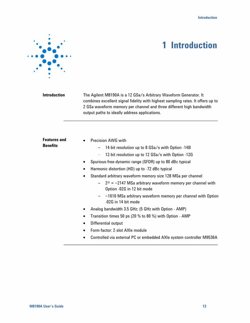
Introduction The Agilent M8190A is a 12 GSa/s Arbitrary Waveform Generator. It
combines excellent signal fidelity with highest sampling rates. It offers up to
2 GSa waveform memory per channel and three different high bandwidth
output paths to ideally address applications.
Features and
Benefits
Precision AWG with
14-bit resolution up to 8 GSa/s with Option -14B
12-bit resolution up to 12 GSa/s with Option -12G
Spurious-free-dynamic range (SFDR) up to 80 dBc typical
Harmonic distortion (HD) up to -72 dBc typical
Standard arbitrary waveform memory size 128 MSa per channel
231 = ~2147 MSa arbitrary waveform memory per channel with
Option -02G in 12 bit mode
~1610 MSa arbitrary waveform memory per channel with Option
-02G in 14 bit mode
Analog bandwidth 3.5 GHz; (5 GHz with Option - AMP)
Transition times 50 ps (20 % to 80 %) with Option - AMP
Differential output
Form-factor: 2-slot AXIe module
Controlled via external PC or embedded AXIe system controller M9536A
14
Additional
Documents
Additional documentation can be found at:
http://www.agilent.com/find/M9505A for 5-slot chassis related
documentation.
http://www.agilent.com/find/M9502A for 2-slot chassis related
documentation.
http://www.agilent.com/find/M9045A for PCIe laptop adapter card related
documentation.
http://www.agilent.com/find/M9047A for PCIe desktop adapter card
related documentation.
http://www.agilent.com/find/M9536A for embedded AXIe controller
related documentation.
http://www.agilent.com/find/M8190A for AXIe based AWG module related
documentation.
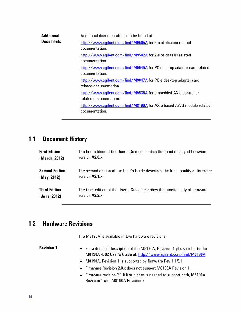
1.1 Document History
First Edition
(March, 2012)
The first edition of the User’s Guide describes the functionality of firmware
version V2.0.x.
Second Edition
(May, 2012)
The second edition of the User’s Guide describes the functionality of firmware
version V2.1.x.
Third Edition
(June, 2012)
The third edition of the User’s Guide describes the functionality of firmware
version V2.2.x.
1.2 Hardware Revisions
The M8190A is available in two hardware revisions.
Revision 1 For a detailed description of the M8190A, Revision 1 please refer to the
M8190A -B02 User's Guide at: http://www.agilent.com/find/M8190A
M8190A, Revision 1 is supported by firmware Rev 1.1.5.1
Firmware Revision 2.0.x does not support M8190A Revision 1
Firmware revision 2.1.0.0 or higher is needed to support both, M8190A
Revision 1 and M8190A Revision 2

Introduction
M8190A User’s Guide 15
Figure 1-1: Panel of M8190A, Revision 1, 2 Channels
Revision 2 This User's Guide covers M8190A Revision 2 along with firmware revision
2.1.0.0 or higher
Figure 1-2: Front Panel of M8190A, Revision 2, 2 Channels
Figure 1-3: Front Panel of M8190A, Revision 2, 1 channel
16
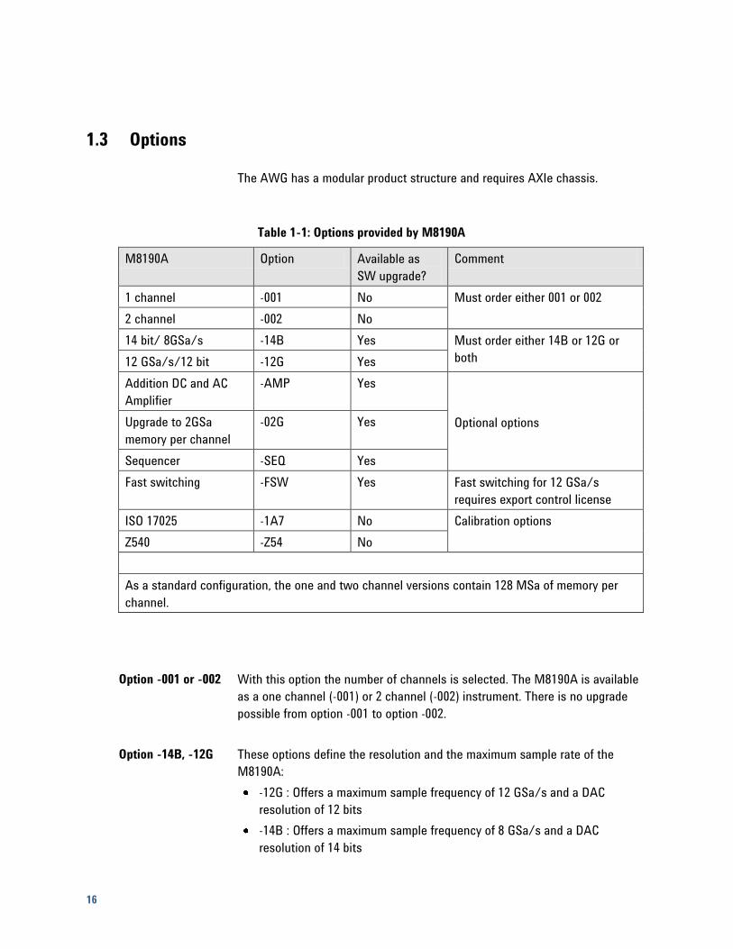
1.3 Options
The AWG has a modular product structure and requires AXIe chassis.
Table 1-1: Options provided by M8190A
M8190A Option Available as
SW upgrade?
Comment
1 channel -001 No Must order either 001 or 002
2 channel -002 No
14 bit/ 8GSa/s -14B Yes Must order either 14B or 12G or
both 12 GSa/s/12 bit -12G Yes
Addition DC and AC
Amplifier
-AMP Yes
Optional options Upgrade to 2GSa
memory per channel
-02G Yes
Sequencer -SEQ Yes
Fast switching -FSW Yes Fast switching for 12 GSa/s
requires export control license
ISO 17025 -1A7 No Calibration options
Z540 -Z54 No
As a standard configuration, the one and two channel versions contain 128 MSa of memory per
channel.
Option -001 or -002 With this option the number of channels is selected. The M8190A is available
as a one channel (-001) or 2 channel (-002) instrument. There is no upgrade
possible from option -001 to option -002.
Option -14B, -12G These options define the resolution and the maximum sample rate of the
M8190A:
-12G : Offers a maximum sample frequency of 12 GSa/s and a DAC
resolution of 12 bits
-14B : Offers a maximum sample frequency of 8 GSa/s and a DAC
resolution of 14 bits
Introduction
M8190A User’s Guide 17
Every M8190A must have minimum one of the two option (-12G or -14B). Both
options can be installed in parallel on the M8190A. If both options are
installed, it is possible to switch between the 12 bit and 14 bit mode by
software configuration. Also, a software upgrade for the options is possible.
Option -AMP This option enables two additional output amplifiers. This gives a total of three
selectable output paths.
1. Direct Output: Optimized for optimum Spurious Free Dynamic Range
(SFDR), Harmonic Distortions (HD)
2. DC Output: Optimized for Serial Data Applications. This amplifier offers up
to 1V amplitude, a voltage window of -1 V to +3.3 V and an external
termination voltage window of -1 V to +3.3 V.
3. AC Output: Optimized for RF applications. This amplifier offers up to 2V
amplitude, 5 GHz bandwidth, flatness correction – including sinx/x
compensation at 12 GSa/s.
Refer to the data sheet for detailed specification.
Without –AMP, the M8190A offers a Direct Output path.
Option –AMP is software upgradeable.
Option -02G This option offers 2 GSa waveform memory per channel.
Without –02G, the M8190A offers 128 MSa waveform memory per channel.
Option –02G is software upgradeable.
Option -SEQ This option offers extensive sequencing capabilities. For details refer to
chapter Characteristics.
Option –SEQ is software upgradeable.
Option -FSW This option enables the M8190A to externally select or step through segments
or sequences faster than every 100 µs.
Option –FSW is export controlled and is software upgradeable.
Option -1A7, -Z54 Calibration options
18
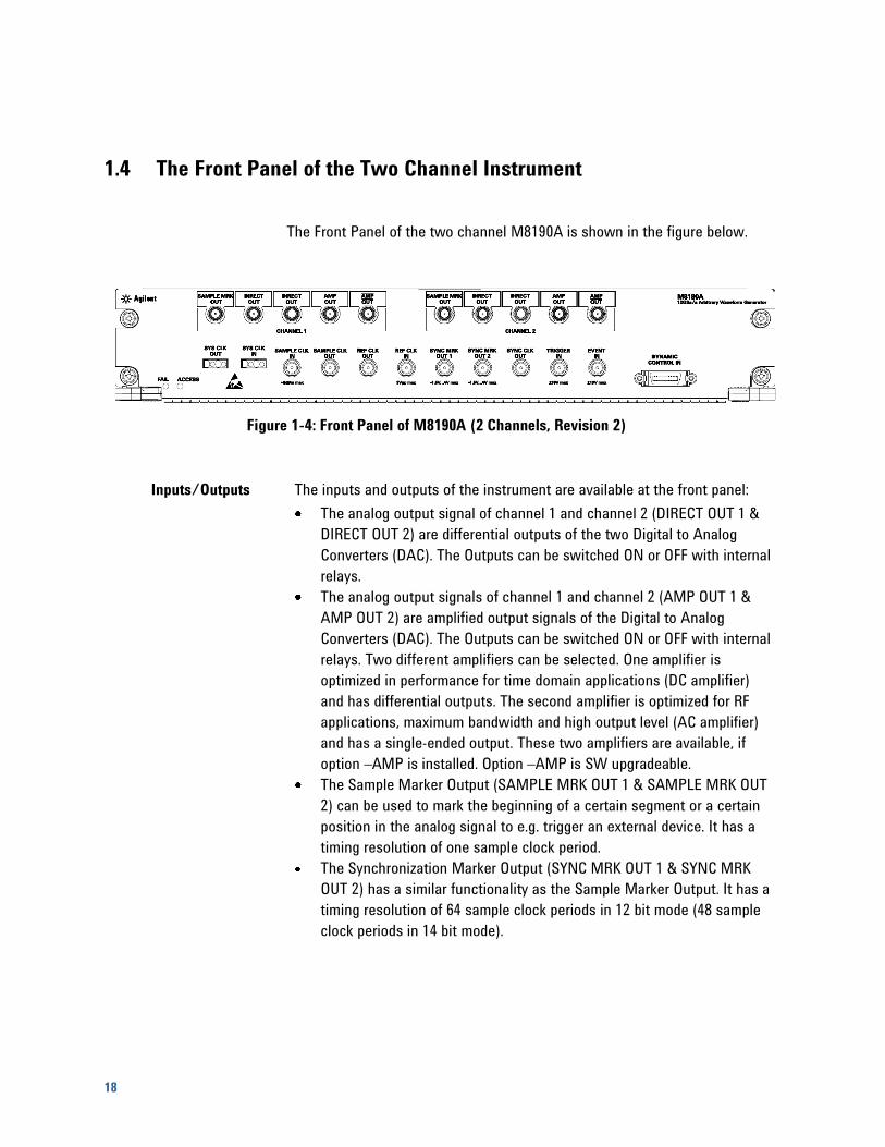
1.4 The Front Panel of the Two Channel Instrument
The Front Panel of the two channel M8190A is shown in the figure below.
Figure 1-4: Front Panel of M8190A (2 Channels, Revision 2)
Inputs/Outputs The inputs and outputs of the instrument are available at the front panel:
The analog output signal of channel 1 and channel 2 (DIRECT OUT 1 &
DIRECT OUT 2) are differential outputs of the two Digital to Analog
Converters (DAC). The Outputs can be switched ON or OFF with internal
relays.
The analog output signals of channel 1 and channel 2 (AMP OUT 1 &
AMP OUT 2) are amplified output signals of the Digital to Analog
Converters (DAC). The Outputs can be switched ON or OFF with internal
relays. Two different amplifiers can be selected. One amplifier is
optimized in performance for time domain applications (DC amplifier)
and has differential outputs. The second amplifier is optimized for RF
applications, maximum bandwidth and high output level (AC amplifier)
and has a single-ended output. These two amplifiers are available, if
option –AMP is installed. Option –AMP is SW upgradeable.
The Sample Marker Output (SAMPLE MRK OUT 1 & SAMPLE MRK OUT
2) can be used to mark the beginning of a certain segment or a certain
position in the analog signal to e.g. trigger an external device. It has a
timing resolution of one sample clock period.
The Synchronization Marker Output (SYNC MRK OUT 1 & SYNC MRK
OUT 2) has a similar functionality as the Sample Marker Output. It has a
timing resolution of 64 sample clock periods in 12 bit mode (48 sample
clock periods in 14 bit mode).
Introduction
M8190A User’s Guide 19
The Trigger Input (TRIGGER IN) has a combined functionality as Trigger
or Gate and is used to start the M8190A by an external signal. This input
is defined in detail in chapter Sequencing.
The Event Input (EVENT IN) is used to e.g. step through segments or
scenarios by an external signals. This input is defined in detail in
chapter Sequencing.
The Sample Clock Input (SAMPLE CLK IN) can be used, if an external
clock source shall be used to clock the Digital to Analog Converters.
The Sample Clock Output (SAMPLE CLK OUT) can be used to output the
clock signal from the internal sample clock or the sample clock input.
The Reference Clock Input (REF CLK IN) can be used to synchronize to
an external clock. The input frequency can vary between 1MHz and
200 MHz.
The Reference Clock Output (REF CLK OUT) can be used to synchronize
a DUT to the M8190A. The output frequency is 100MHz.
The Sync Clock Output (SYNC CLK OUT) can be used to synchronize a
DUT to the M8190A. E.g. the set-up and hold timings of the Trigger
Input, Event Input or Dynamic Control Input signals refer to the Synch
Clock Output.
The Dynamic Control Input (DYNAMIC CONTROL IN) offers a 19 bit wide
parallel interface to select the 512k segments externally. This input is
defined in detail in chapter Sequencing.
The System Clock Input (SYS CLK IN) and System Clock Output (SYS
CLK OUT) are reserved for future use. Do not connect!
Status LED Two LEDs are available at the front panel to indicate the status of the AWG
module:
The green ‘Access’ LED indicates that the controlling PC exchanges data
with the AWG module.
The red ‘Fail’ LED has following functionality:
It is ‘ON’ for about 30 seconds after powering the AXIe chassis.
After about 30 seconds the LED is switched ‘OFF’. If an external PC is
used to control the AXIe chassis, this PC can be powered after this LED
has switched OFF.
During normal operation of the module this LED is ‘OFF’. In case of an
error condition such as e.g. a self-test error, the LED is switch ‘ON’.
In case the output relay has shut-off because of an external overload
condition, this LED flashes.
20
1.5 The Front Panel of the One Channel Instrument
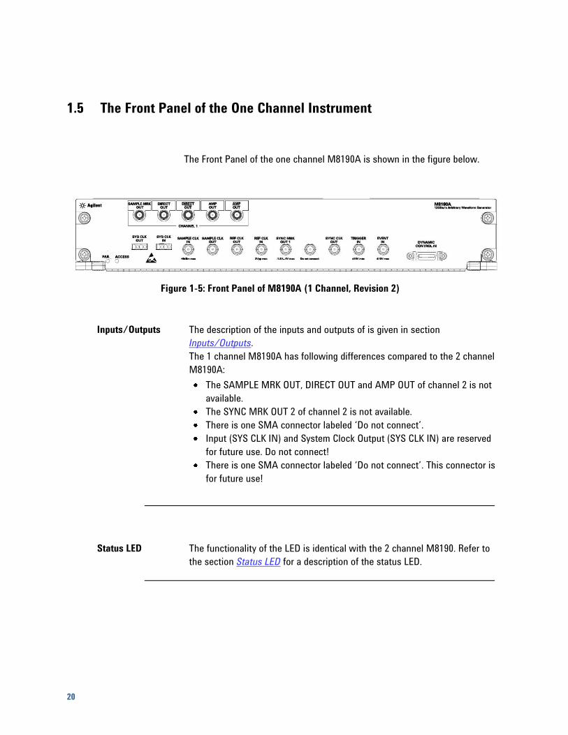
The Front Panel of the one channel M8190A is shown in the figure below.
Figure 1-5: Front Panel of M8190A (1 Channel, Revision 2)
Inputs/Outputs The description of the inputs and outputs of is given in section
Inputs/Outputs.
The 1 channel M8190A has following differences compared to the 2 channel
M8190A:
The SAMPLE MRK OUT, DIRECT OUT and AMP OUT of channel 2 is not
available.
The SYNC MRK OUT 2 of channel 2 is not available.
There is one SMA connector labeled ‘Do not connect’.
Input (SYS CLK IN) and System Clock Output (SYS CLK IN) are reserved
for future use. Do not connect!
There is one SMA connector labeled ‘Do not connect’. This connector is
for future use!
Status LED The functionality of the LED is identical with the 2 channel M8190. Refer to
the section Status LED for a description of the status LED.
Introduction
M8190A User’s Guide 21
1.6 Modes of Operation
1.6.1 Block Diagram
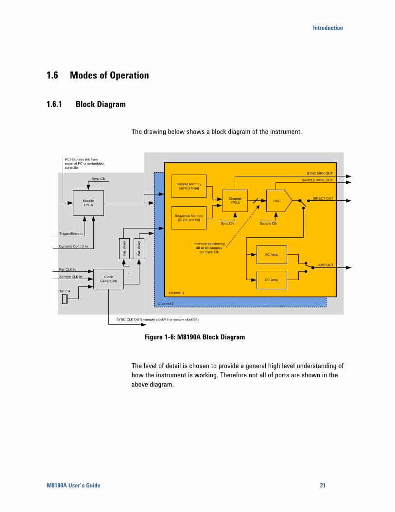
The drawing below shows a block diagram of the instrument.
Module
FPGA
Clock
Generation
Sample Memory
(up to 2 GSa)
Sequence Memory
(512 K entries)
Channel
FPGA
AC Amp.
DC Amp.
PCI-Express link from
external PC or embedded
controller
Sync Clk
Int. Clk
SYNC CLK OUT(=sample clock/48 or sample clock/64)
Va
r. d
ela
y
Va
r. d
ela
y
Sync Clk
DAC
Sample Clk
AMP OUT
DIRECT OUT
SAMPLE MRK_OUT
SYNC MRK OUT
Interface transferring
48 or 64 samples
per Sync Clk
Channel 1
Channel 2
Trigger/Event In
Dynamic Control In
Ref CLK In
Sample CLK In
Figure 1-6: M8190A Block Diagram
The level of detail is chosen to provide a general high level understanding of
how the instrument is working. Therefore not all of ports are shown in the
above diagram.
22
Channel
The data generation consists of a Sample Memory which contains the
sample data, a Sequence Memory which contains the required information
for sequencing like the sequence structure or loop counter values and a
Channel FPGA which combines both into a sequence controlled sample
stream. These parts cannot run at sample clock rate and therefore multiple
samples must be executed in parallel at a lower clock speed. Depending on
the selected mode, the Sync Clock, also called Sequencer Clock is the
sample clock divided by 48 (high speed mode) or by 40 (high precision
mode).
The DAC converts the parallel sample stream to sample clock granularity.
The analog output of the DAC can either be used directly at the DIRECT OUT
pin or can be routed through two different available amplifier paths.
Clock Generation
The clock generator can work on three clock sources: External Reference
Clock (REF CLK IN), the SAMPLE CLK IN or an internally generated clock.
The two channels can be delayed independently. The SYNC CLK OUT can be
used to source the user’s environment to provide synchronous signals at the
TRIGGER IN and at the EVENT IN.
The Module FPGA
The Module FPGA is the common point of the instrument. The PCIe link is
connected to it as well as the Trigger and Event input and the port used for
dynamic sequencing. The whole chain from the Trigger/Event input to the
Channel FPGA is sourced with the Sync Clock. This allows providing an
exact output delay from the inputs to the DAC output for all cases where
triggers and events are generated based on the Sync Clock output and
where the corresponding setup and hold time conditions are met.
Introduction
M8190A User’s Guide 23
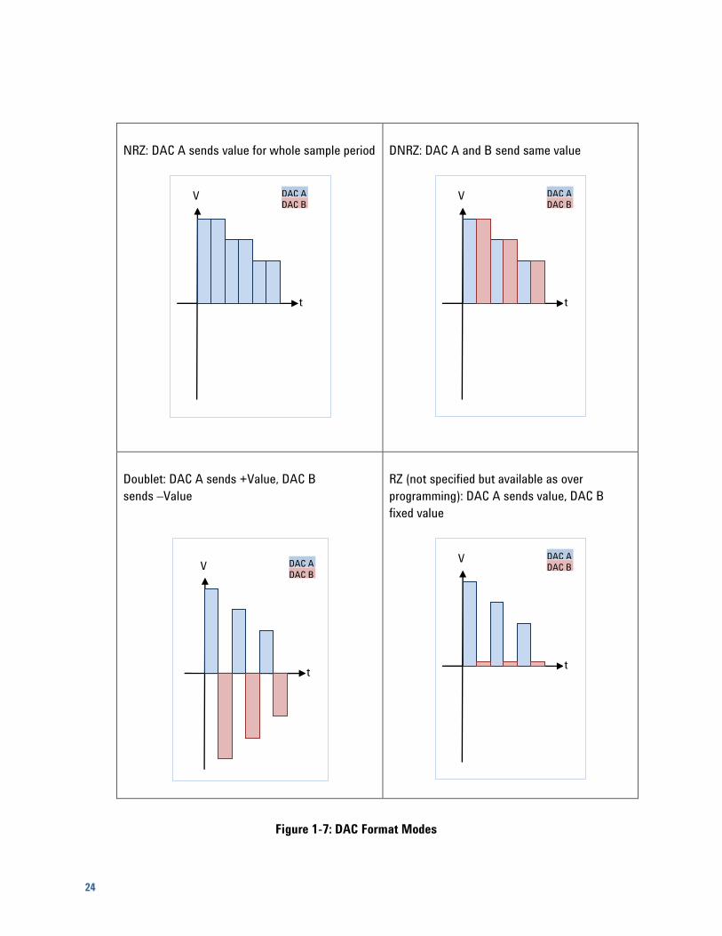
1.6.2 NRZ / DNRZ / Doublet
DAC Format Modes Each channel uses two DACs (A & B) which are internally used. Each DAC
usually contributes to signal 50% of a sample period.
The following three DAC format modes are available:
NRZ (Non Return to Zero)
DNRZ, (Double NRZ)
Doublet
In addition there is: (not specified but available as over programming)
RZ (Return to Zero)
24
NRZ: DAC A sends value for whole sample period
DNRZ: DAC A and B send same value
Doublet: DAC A sends +Value, DAC B
sends –Value
RZ (not specified but available as over
programming): DAC A sends value, DAC B
fixed value
Figure 1-7: DAC Format Modes
t
V DAC B
DAC A
t
V DAC B
DAC A
t
V DAC B
DAC A
t
V DAC B
DAC A
Introduction
M8190A User’s Guide 25
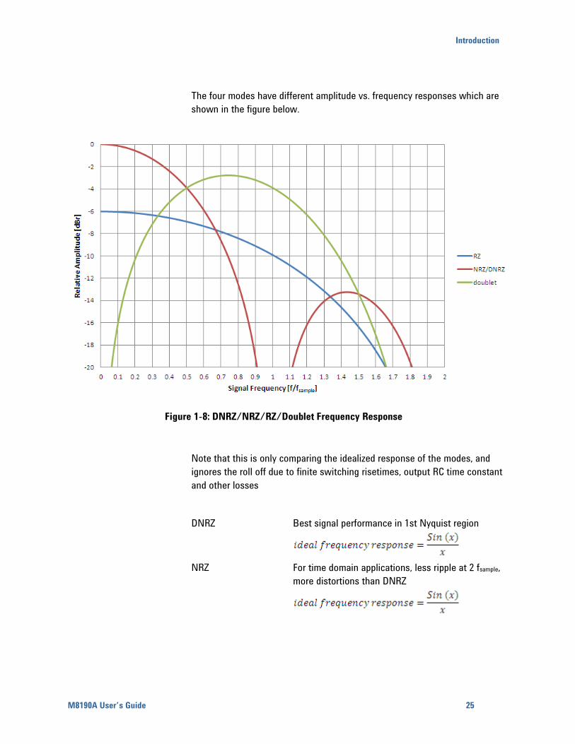
The four modes have different amplitude vs. frequency responses which are
shown in the figure below.
Figure 1-8: DNRZ/NRZ/RZ/Doublet Frequency Response
Note that this is only comparing the idealized response of the modes, and
ignores the roll off due to finite switching risetimes, output RC time constant
and other losses
DNRZ Best signal performance in 1st Nyquist region
NRZ For time domain applications, less ripple at 2 fsample,
more distortions than DNRZ
26
Doublet More output power and flatter frequency response
in 2nd Nyquist region limited to fsample > 1 GSa/s
RZ Flatter frequency response in 2nd Nyquist region
than DNRZ/NRZ (but less power than Doublet
mode). Limited to fsample > 1 GSa/s
Attention!: does not return to zero single ended.
(Both signals of the differential output return to a
level slightly above the positive fullscale level, this
is removed when used with AC path or Balun.)
1.6.3 Delay Adjust
In order to compensate for e.g. external cable length differences as well as
the initial skew, channel 1 and channel 2 can be independently delayed with
a very high timing resolution.
Setting the variable delay of channel 1 to 10 ps has following effect:
Direct Out1 (or Amp Out1, if selected) is delayed by 10 ps with respect
to following signals: Sample Clock Out, Synch Marker Out1, Synch
Marker Out2, Direct Out2 (or Amp Out2, if selected), Trigger / Gate
Input, Event Input
Sample Marker Out1 is delayed by 10 ps with respect to following
signals: Sample Clock Out, Synch Marker Out1, Synch Marker Out2,
Direct Out2 (or Amp Out2, if selected), Trigger / Gate Input, Event Input
Note: Modifying the variable delay of one channel always affects the delay
of the Analog Output AND the Sample Marker of that channel.
The variable delay is split into two delay elements:
1. Fine delay
2. Coarse delay
The Variable Delay is the sum of Fine Delay and Coarse Delay. If a de-skew
between channel 1 and channel 2 is needed, adjust in the first step the
coarse delay to the optimum position. In the second step, use the fine delay
to perfectly align both channels.
Introduction
M8190A User’s Guide 27
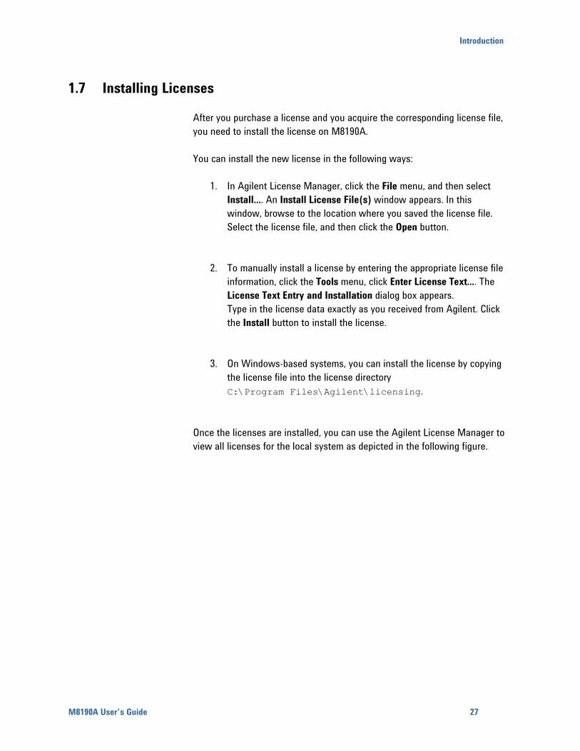
1.7 Installing Licenses
After you purchase a license and you acquire the corresponding license file,
you need to install the license on M8190A.
You can install the new license in the following ways:
1. In Agilent License Manager, click the File menu, and then select
Install.... An Install License File(s) window appears. In this
window, browse to the location where you saved the license file.
Select the license file, and then click the Open button.
2. To manually install a license by entering the appropriate license file
information, click the Tools menu, click Enter License Text.... The
License Text Entry and Installation dialog box appears.
Type in the license data exactly as you received from Agilent. Click
the Install button to install the license.
3. On Windows-based systems, you can install the license by copying
the license file into the license directory
C:\Program Files\Agilent\licensing.
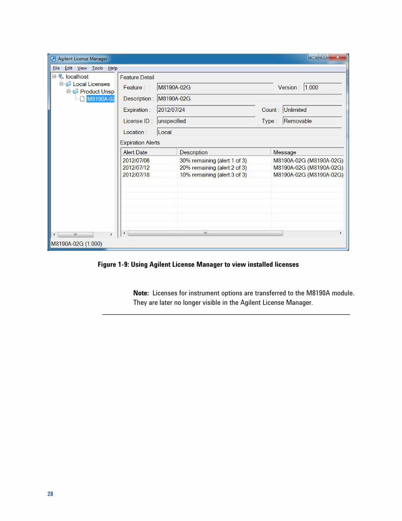
Once the licenses are installed, you can use the Agilent License Manager to
view all licenses for the local system as depicted in the following figure.
28
Figure 1-9: Using Agilent License Manager to view installed licenses
Note: Licenses for instrument options are transferred to the M8190A module.
They are later no longer visible in the Agilent License Manager.

M8190A User Interface
M8190A User’s Guide 29
2 M8190A User Interface
2.1 Introduction
This chapter describes the M8190A Soft Front Panel.
2.2 Launching the M8190A Soft Front Panel
There are three ways to launch the M8190A Soft Front Panel:
1. Select Start – All Programs – Agilent – M8190 – Soft Front Panel from
the Start Menu.
2. From the Agilent Connection Expert select the discovered M8190
module, press the right mouse key to open the context menu and
select “Send Commands To This Instrument”.
3. From the Agilent Connection Expert select the discovered M8190
module, select the “Installed Software” tab and press the “Start SFP”
button.
30
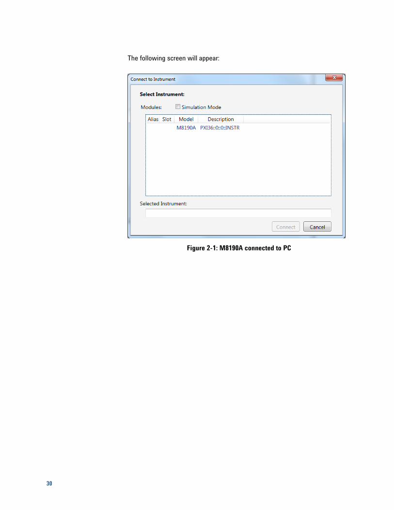
The following screen will appear:
Figure 2-1: M8190A connected to PC
M8190A User Interface
M8190A User’s Guide 31
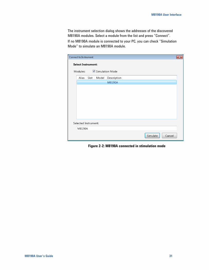
The instrument selection dialog shows the addresses of the discovered
M8190A modules. Select a module from the list and press “Connect”.
If no M8190A module is connected to your PC, you can check “Simulation
Mode” to simulate an M8190A module.
Figure 2-2: M8190A connected in stimulation mode
32
2.3 M8190A User Interface Overview
The M8190A user interface includes the following GUI items:
Title Bar
Menu Bar
Status Bar
Clock/Output/Aux Tabs
Status/Control Tab
The detailed information on these GUI items is given in the sections that
follow.
2.3.1 Title Bar
The title bar contains the standard Microsoft Windows elements such as the
window title and the icons for minimizing, maximizing, or closing the window.
2.3.2 Menu Bar
The menu bar consists of various pull down menus that provide access to the
different functions and launch interactive GUI tools.
The menu bar includes the following pull down menu:
File
View
Utilities
Tools
Help
Each pull down menu and its options are described in the following sections.
M8190A User Interface
M8190A User’s Guide 33
2.3.2.1 File Menu
The File menu includes the following selections:
File – Connect…
Opens the instrument selection dialog.
File – Save Configuration As…
Saves configuration as a text file.
File – Load Configuration…
Load the previously saved configuration file.
File – Import File…
Opens the Waveform File Import Dialog.
File – Exit
Exits the user interface.
2.3.2.2 View Menu
The View menu includes the following selections:
View – Refresh
Reads the instrument state and updates all fields.
View – Auto Refresh
Reads the instrument state periodically and updates all fields.

34
2.3.2.3 Utility Menu
The Utility menu includes the following selections:
Utility – Reset
Resets the instrument, reads the state and updates all fields.
Utility – Errors…
Opens the Errors Window to display the errors reported by the instrument.
Utility – Self Test…
Opens a window to start the self test and display the result after
completion.
2.3.2.4 Tools Menu
The Tools menu includes the following selections:
Tools – Monitor Driver Calls
Opens the Driver Call Log.
2.3.2.5 Help Menu
The Help menu includes the following selections:
Help – Driver Help
Opens the IVI driver online help.
Help – Online Support
Opens the instrument’s product support web page.
Help – About
Displays revision information for hardware, software and firmware.
Displays the serial number of the connected module.
M8190A User Interface
M8190A User’s Guide 35
2.3.3 Status Bar
The Status Bar contains three fields from left to right:
Connection state
“Not Connected” – No instrument is connected.
“Connected: <Instrument resource string>” – An instrument is connected.
The resource string, for example PXI36::0::0::INSTR is displayed.
“Simulation Mode” – No real instrument is connected. The user interface
is in simulation mode.
Click this field to open the Instrument Selection Dialog.
Instrument status
Displays the instrument status, for example “Reset complete” after issuing
a reset command. In case of error it displays additional error information.
Error status
“Error” – The connected instrument reported an error.
“No Error” – No errors occurred.
Click this field to open the Report Error Window.
2.3.4 Clock/Output/Aux/Status/Control Tabs
These tabs are used to configure the most important parameters of the
M8190A module. They are described in detail in the following sections.
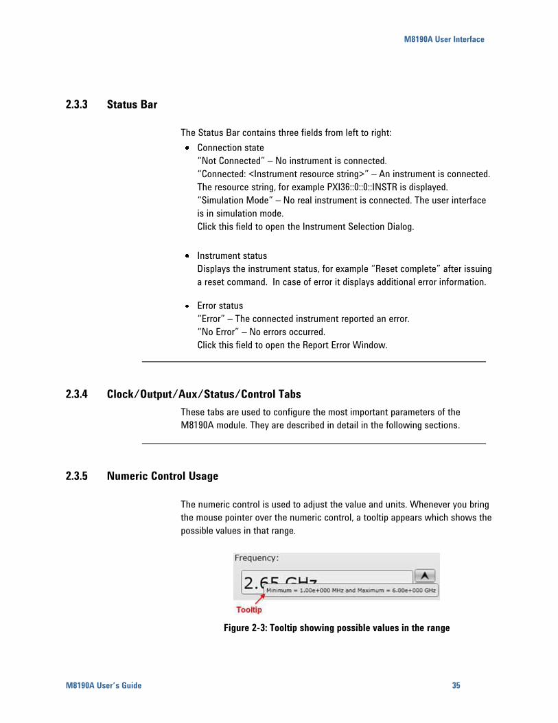
2.3.5 Numeric Control Usage
The numeric control is used to adjust the value and units. Whenever you bring
the mouse pointer over the numeric control, a tooltip appears which shows the
possible values in that range.
Figure 2-3: Tooltip showing possible values in the range
36
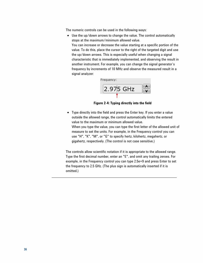
The numeric controls can be used in the following ways:
Use the up/down arrows to change the value. The control automatically
stops at the maximum/minimum allowed value.
You can increase or decrease the value starting at a specific portion of the
value. To do this, place the cursor to the right of the targeted digit and use
the up/down arrows. This is especially useful when changing a signal
characteristic that is immediately implemented, and observing the result in
another instrument. For example, you can change the signal generator’s
frequency by increments of 10 MHz and observe the measured result in a
signal analyzer:
Figure 2-4: Typing directly into the field
Type directly into the field and press the Enter key. If you enter a value
outside the allowed range, the control automatically limits the entered
value to the maximum or minimum allowed value.
When you type the value, you can type the first letter of the allowed unit of
measure to set the units. For example, in the Frequency control you can
use "H", "K", "M", or "G" to specify hertz, kilohertz, megahertz, or
gigahertz, respectively. (The control is not case sensitive.)
The controls allow scientific notation if it is appropriate to the allowed range.
Type the first decimal number, enter an "E", and omit any trailing zeroes. For
example, in the Frequency control you can type 2.5e+9 and press Enter to set
the frequency to 2.5 GHz. (The plus sign is automatically inserted if it is
omitted.)
M8190A User Interface
M8190A User’s Guide 37
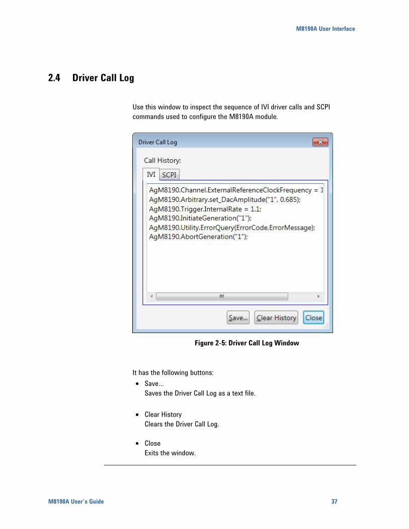
2.4 Driver Call Log
Use this window to inspect the sequence of IVI driver calls and SCPI
commands used to configure the M8190A module.
Figure 2-5: Driver Call Log Window
It has the following buttons:
Save…
Saves the Driver Call Log as a text file.
Clear History
Clears the Driver Call Log.
Close
Exits the window.
38
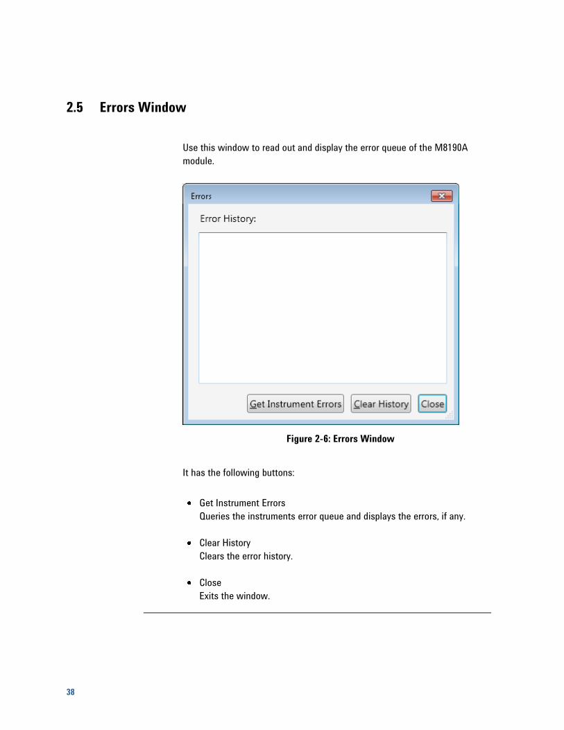
2.5 Errors Window
Use this window to read out and display the error queue of the M8190A
module.
Figure 2-6: Errors Window
It has the following buttons:
Get Instrument Errors
Queries the instruments error queue and displays the errors, if any.
Clear History
Clears the error history.
Close
Exits the window.
M8190A User Interface
M8190A User’s Guide 39
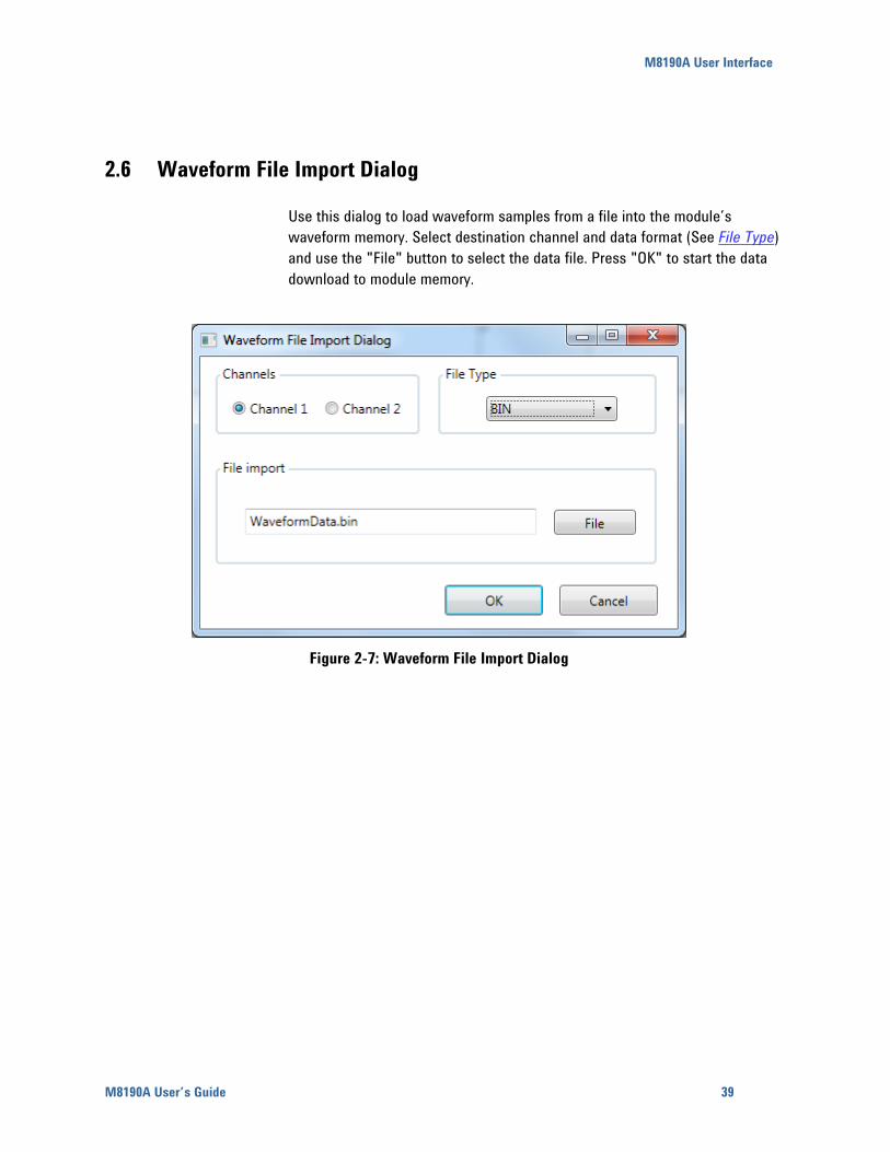
2.6 Waveform File Import Dialog
Use this dialog to load waveform samples from a file into the module’s
waveform memory. Select destination channel and data format (See File Type)
and use the "File" button to select the data file. Press "OK" to start the data
download to module memory.
Figure 2-7: Waveform File Import Dialog
40
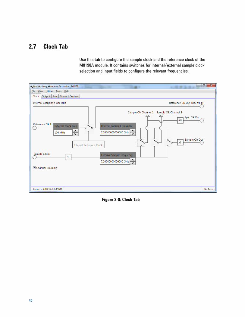
2.7 Clock Tab
Use this tab to configure the sample clock and the reference clock of the
M8190A module. It contains switches for internal/external sample clock
selection and input fields to configure the relevant frequencies.
Figure 2-8: Clock Tab
M8190A User Interface
M8190A User’s Guide 41
Reference clock selection switch
This switch selects between the different reference clock sources.
Internal: Reference from internal oscillator.
(Revision 1 hardware only)
Internal Backplane 100 MHz: Reference from AXI Backplane.
(Revision 2 hardware only)
External: Reference from Ref Clock In (Revision 2 hardware only)
Sample clock selection switch for channel 1 and 2
These switches select between internal and external sample clock for
channel 1 and 2.
Sample clock output configuration switch
This switch selects which sample clock - either internal or external - is
present at the sample clock output.
Internal sample frequency
If internal sample clock is selected, this field specifies the frequency of the
internally generated sample clock.
External sample frequency
If external sample clock is selected, this field specifies the frequency of
the used external clock source. For sample frequencies below 1 GHz the
frequency at the Sample Clk In must be a multiple of the desired sample
frequency, see command [:SOURce]:FREQuency:RASTer:EXTernal[?]
frequency|MINimum|MAXimum. The ratio is shown on the divider
symbol.
External reference frequency
If external reference clock is selected, this field specifies the frequency of
the used external reference clock.
Channel Coupling
Use this check box to select the coupling mode of the two channels. The
channels can operate in coupled or uncoupled mode.
42
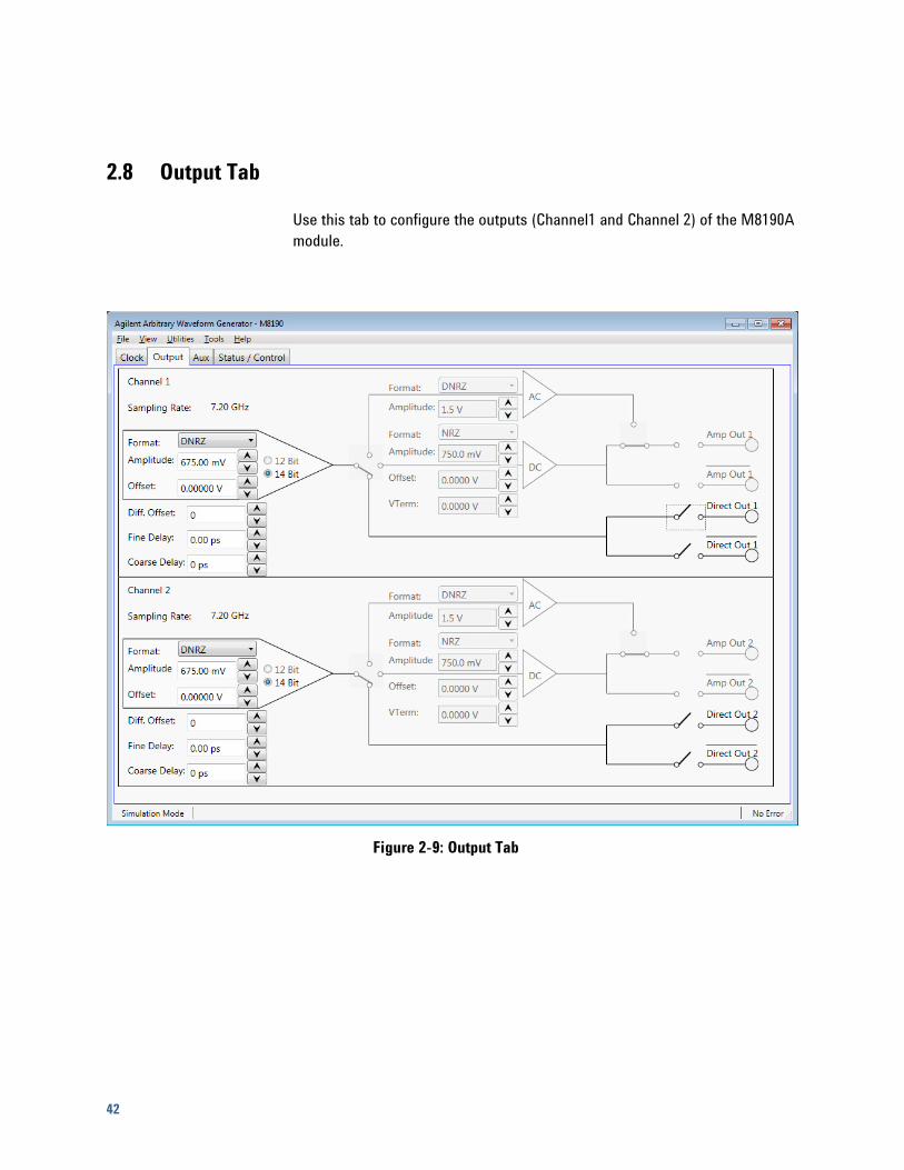
2.8 Output Tab
Use this tab to configure the outputs (Channel1 and Channel 2) of the M8190A
module.
Figure 2-9: Output Tab
M8190A User Interface
M8190A User’s Guide 43
The two channels have the following input fields.
DAC format mode
Selects between the DAC Format Modes. Internally two DACs are used (A,
B). Each usually contributes to signal 50% of a sample period.
NRZ: DAC A sends value for whole sample period.
DNRZ: DAC A and B send same value.
NRZ: DAC A sends value for whole sample period.
DOUBlet: DAC A sends +Value, DAC B sends –Value
DAC width
12-bit mode: DAC has 12-bit resolution.
14-bit mode: DAC has 14-bit resolution.
Output path selection switch
Selects between the three output paths. Depending on this setting the
input fields for offset and termination voltage are applicable or not.
DAC: Direct DAC output
DC: Amplified differential output
AC: Single ended AC coupled output with up to 10 dBm output
level
Amplitude
Specifies the amplitude of the output signal.
Offset
Specifies the offset of the output signal.
VTerm
Specifies the termination voltage when the DC output path is selected.
Output enable switches
If set to closed position, the generated signal is present at the output.
Fine Delay
Specifies the fine delay portion of the variable delay (see available Range).
Coarse Delay
Specifies the coarse delay portion of the variable delay. See available
Range and Resolution.
Differential offset.
Specifies an offset adjustment to compensate for small offset differences
between normal and complement output.
44
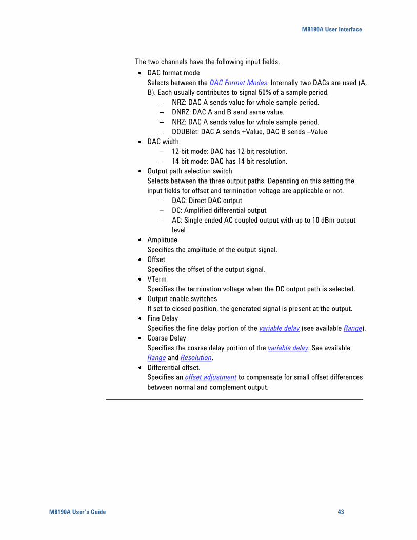
2.9 Aux Tab
Use this tab to configure the external trigger and event inputs and the marker
outputs of the M8190A module.
Figure 2-10: Aux Tab

M8190A User Interface
M8190A User’s Guide 45
This tab has the following input fields.
Threshold for trigger and event input
Sets threshold level.
Polarity for trigger and event input
Sets the polarity for the input.
Positive – rising edge
Negative – falling edge
Either - both
Impedance for trigger and event input
Sets the impedance of the input.
Low – 50 Ohm
High – 1k Ohm
Internal trigger frequency
Sets the frequency of the internal trigger generator.
Trigger source selection switch
Selects between external trigger input and internal trigger generator.
Enable event selection switch
Selects the source for the enable event, either trigger input or event input.
Advancement event selection switch
Selects the source for the advancement event, either trigger input or event
input.
Amplitude for marker outputs
Specifies the amplitude of the marker output signal.
Offset for marker outputs
Specifies the offset of the marker output signal.
46
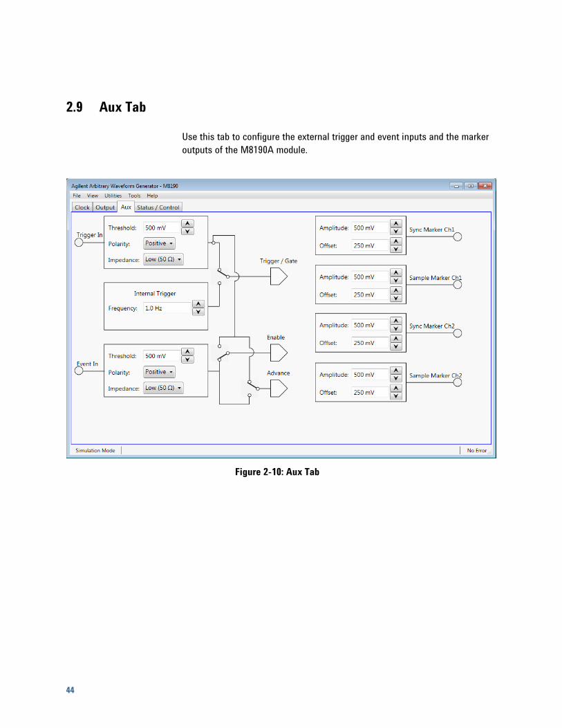
2.10 Status/Control Tab
This tab displays the most important status information of the M8190A
module. Use this tab to start and stop signal generation and to send software
triggers and events to the module.
Figure 2-11: Status/Control Tab

M8190A User Interface
M8190A User’s Guide 47
This tab has the following controls.
Sequencer Modes
Arbitrary – Generate arbitrary waveform segments.
STSequence – Generate sequences of segments.
STSScenario – Generate scenarios (sequences of sequences).
Arm mode
Armed – Signal generation starts when an “enable” is received.
Self – Signal generation starts as defined by the trigger mode.
Trigger mode
Continuous – Signal generation starts immediately after pressing the Run
button. No trigger needed.
Triggered – Signal generation starts after a trigger is received.
Gated – Signal generation starts when a rising edge is received on the
trigger input and pauses when a falling edge is received. Signal generation
restarts after the next rising edge.
Dynamic Control Enable
Use this check box to enable or disable dynamic segment or sequence
selection mode.
Valid Bits
Selects the bit width of the dynamic control port.
AllBits – The complete width of 19 bits is used for segment or sequence
selection.
LowerBits – The 13 lowest bits are used for segment or sequence
selection. The upper 6 bits are set to 0.
Segment#
Selects the segment to be played in sequencing mode “Arbitrary”. In
dynamic segment selection mode it selects the segment that is played
before the first segment is dynamically selected.
Pressing the “Select..” button opens a list box with the available segments
and their lengths.
Sequence#
Selects the sequence to be played in sequencing mode “STSequence”. In
dynamic sequence selection mode it selects the sequence that is played
before the first sequence is dynamically selected.
Pressing the “Select..” button opens a list box with the available
sequences and their lengths. This list box only display the sequences
defined using the commands in the Sequence subsystem and not the
sequences defined using the commands in the STABle subsystem.

48
Run/Stop
Use this button to switch between Run and Program mode per channel.
Force Trigger
Use this button to send a software trigger to a channel.
Force Event
Use this button to send a software event to a channel.
Force Enable
Use this button to send a software “enable” to a channel.
Installed Options
This field displays the installed options of the module.
Installed Licenses
This field displays the installed licenses.
Sequencing
M8190A User’s Guide 49
3 Sequencing
3.1 Introduction
This chapter describes the sequencing capabilities of the instrument when
having ordered the option sequencing.
3.1.1 Option Sequencing
Without the option sequencing the capabilities of the instrument are limited to
one segment which can be played in the non-dynamic arbitrary self armed
mode.
3.1.2 Sequence Table
The sequencer is implemented in a table. Each table entry consists of a
sequence vector which contains all the necessary information that is required
to play one single waveform segment like loop counter values, advancement
parameters and references to the sample memory. Multiple adjacent sequence
vectors can also be played together within one run. The first sequence table
entry is marked with a start pointer. After having finished one segment, the
next table entry of the list is selected. If an actually executed segment is the
last segment of a loop a jump to the starting point of the loop might be
initiated depending on the loop count.
50
The following drawing shows an example:
5
10
9
8
7
6
Start PointerWaveform A
Waveform C
Waveform E
Waveform A
Waveform B
Waveform D
Loop
Exit
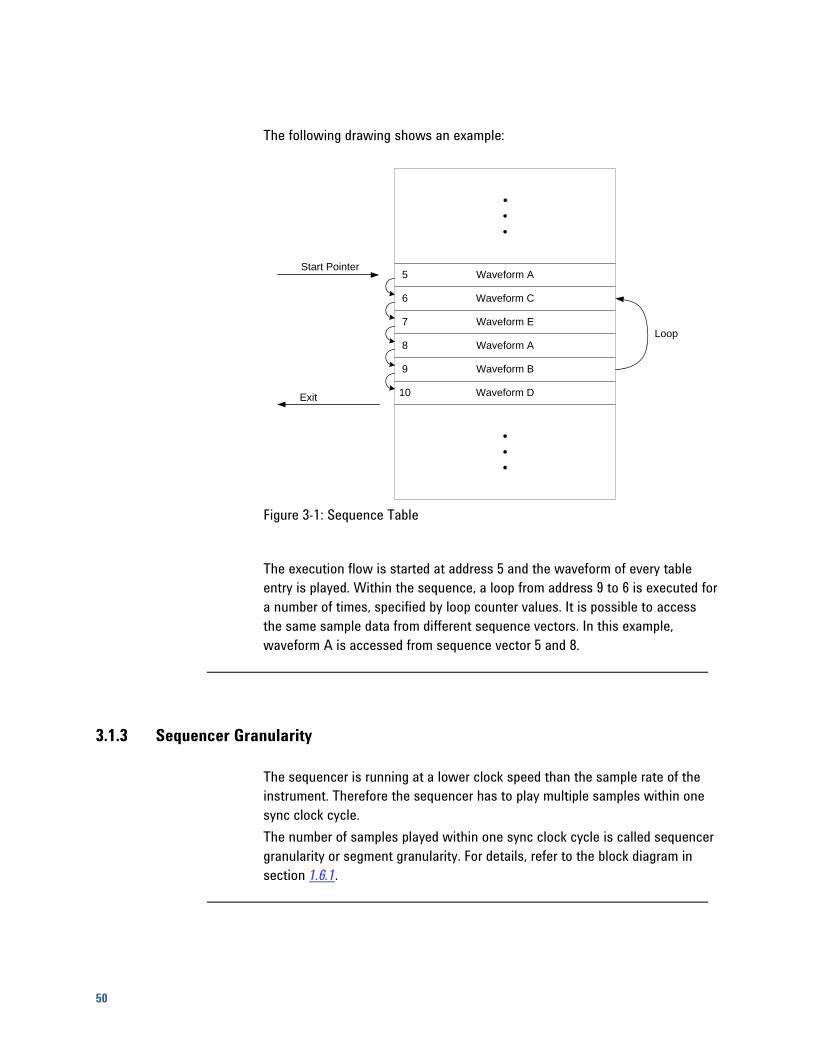
Figure 3-1: Sequence Table
The execution flow is started at address 5 and the waveform of every table
entry is played. Within the sequence, a loop from address 9 to 6 is executed for
a number of times, specified by loop counter values. It is possible to access
the same sample data from different sequence vectors. In this example,
waveform A is accessed from sequence vector 5 and 8.
3.1.3 Sequencer Granularity
The sequencer is running at a lower clock speed than the sample rate of the
instrument. Therefore the sequencer has to play multiple samples within one
sync clock cycle.
The number of samples played within one sync clock cycle is called sequencer
granularity or segment granularity. For details, refer to the block diagram in
section 1.6.1.
Sequencing
M8190A User’s Guide 51
3.2 Sequencing Hierarchy
3.2.1 Segment
A waveform segment consists of a defined number of samples which are
played in a consecutive order. It is treated as a unit and can be repeated a
specified number of times or can run continuously. The sample count of
segments must be in multiples of the sequencer granularity. A minimum length
is also required (see datasheet of the instrument).
A segment can be played standalone (see Arbitrary Mode) or can be part of
a sequence.
3.2.2 Sequence
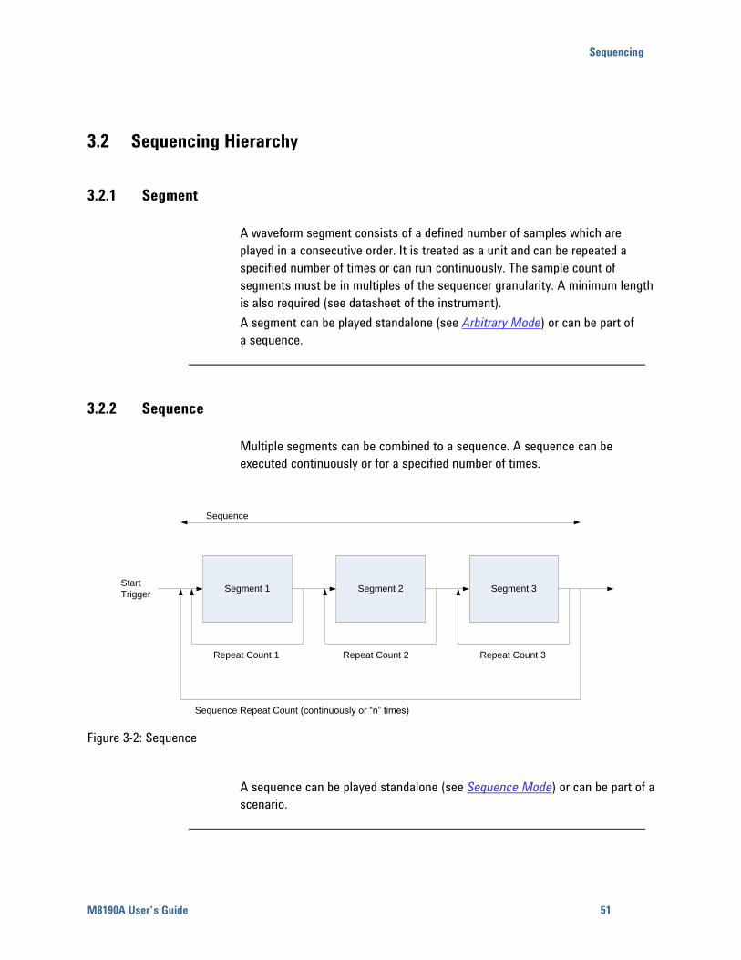
Multiple segments can be combined to a sequence. A sequence can be
executed continuously or for a specified number of times.
Segment 1 Segment 2 Segment 3Start
Trigger
Repeat Count 1 Repeat Count 2 Repeat Count 3
Sequence
Sequence Repeat Count (continuously or “n” times)
Figure 3-2: Sequence
A sequence can be played standalone (see Sequence Mode) or can be part of a
scenario.
52
3.2.3 Scenario
Multiple sequences can be combined into a scenario (see Scenario Mode). A
scenario can be executed continuously or a specified number of times.
3.3 Trigger Modes
The trigger mode defines the way, how segments, sequences and scenarios
begin with playing waveform data. After having setup the instrument, it is
started. Then the start of segments, sequences and scenarios depends on the
different trigger modes.
3.3.1 Auto
In the trigger mode Auto, the sequencer is started immediately after the
instrument. In this mode, the waveform execution is infinite.
3.3.2 Triggered
In the trigger mode Triggered, the sequencer needs a trigger to start. After
having received the trigger, the waveform is played a defined number of times,
and then the sequencer is stopped again and is prepared to accept the next
trigger. Every trigger that occurs before the currently running
segment/sequence/scenario has completed, is ignored. Alternatively, after
having received a trigger, a waveform can also be played infinitely. See
Sequencer Modes for more details.
Sequencing
M8190A User’s Guide 53
3.3.3 Gated
In the trigger mode Gated, both edges of the gate signal are used to start and
stop the execution of the sequencer. After being stopped, the sequencer is
prepared to accept a new rising edge of the gate and can be restarted again.
In Gated Mode, the advancement mode of the top level (e.g. sequence
advancement mode for sequences) must be set to Auto.
3.4 Arm Mode
Sometimes it is desired to play an idle waveform instead of a static idle value
before having started to play the real waveform. With the arm mode it is
possible to select the output signal of the instrument before having started the
sequencer.
3.4.1 Self Armed
Whenever the arm mode is set to Self Armed, the instrument starts as defined
by the selected trigger mode.
3.4.2 Armed
For all cases where the trigger mode is set to Auto and the arm mode to
Armed, the first segment/sequence is played infinitely after start. After having
received a rising edge of Enable, the sequence/scenario advances to the next
segment/sequence and continues to execute as described in trigger mode
Auto. This mode doesn’t make any sense for the execution of standalone
segments or for the trigger modes Triggered and Gated. Therefore in these
cases the described behavior is not available and Armed is treated like Self
Armed with an additional enable flag as start condition.
54
3.5 Advancement Modes
The advancement mode specifies the way of how one element like a segment,
sequence or scenario advances to the next element or how it is repeated.
The advancement mode can be individually specified for each single element.
The exact behavior depends on the sequencing, arm and trigger mode.
There could be different advancement modes on different hierarchy levels.
Some of these modes require an advancement event to proceed. In cases
where the advancement event has to be evaluated simultaneously in multiple
hierarchy levels, the output behavior could be unexpected, especially when
conditional advancement modes are used. For more details, refer to the
examples given in the section Sequencer Modes.
3.5.1 Auto
After having executed all loops, the sequencer advances to the next element
automatically. No external interaction is required for advancement.
3.5.2 Conditional
The sequencer repeats the current element until it receives the correct
advancement event. After having received the advancement event, the current
element is played to the end before switching to the next one.
3.5.3 Repeated
After having executed all loops the sequencer stops and plays the last value of
the current element. After having received the advancement event, the
sequencer starts playing the next element. When receiving the advancement
event before having played all repetitions, all repetitions will be played before
moving to the next element.
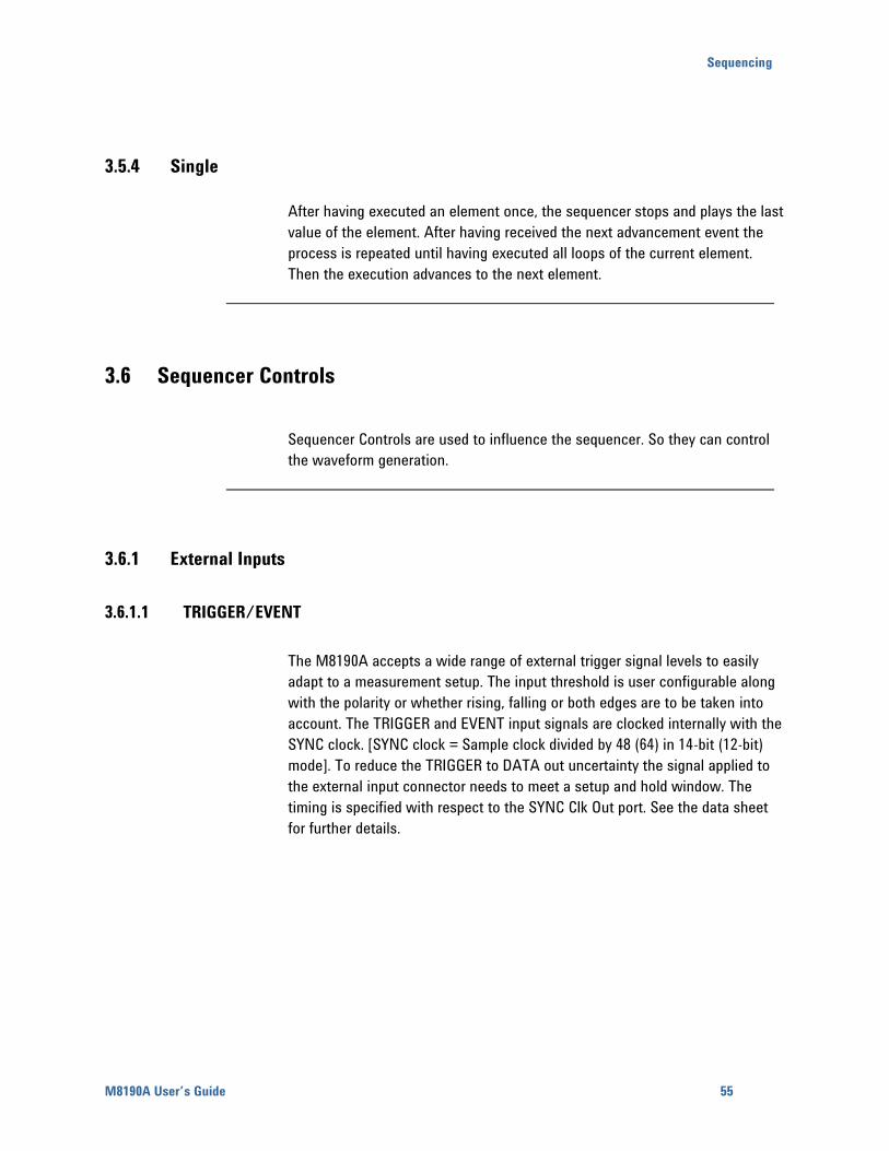
Sequencing
M8190A User’s Guide 55
3.5.4 Single
After having executed an element once, the sequencer stops and plays the last
value of the element. After having received the next advancement event the
process is repeated until having executed all loops of the current element.
Then the execution advances to the next element.
3.6 Sequencer Controls
Sequencer Controls are used to influence the sequencer. So they can control
the waveform generation.
3.6.1 External Inputs
3.6.1.1 TRIGGER/EVENT
The M8190A accepts a wide range of external trigger signal levels to easily
adapt to a measurement setup. The input threshold is user configurable along
with the polarity or whether rising, falling or both edges are to be taken into
account. The TRIGGER and EVENT input signals are clocked internally with the
SYNC clock. [SYNC clock = Sample clock divided by 48 (64) in 14-bit (12-bit)
mode]. To reduce the TRIGGER to DATA out uncertainty the signal applied to
the external input connector needs to meet a setup and hold window. The
timing is specified with respect to the SYNC Clk Out port. See the data sheet
for further details.
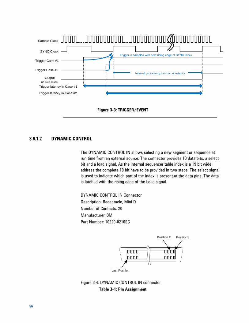
56
Trigger is sampled with next rising edge of SYNC Clock
Sample Clock
SYNC Clock
Trigger Case #1
Trigger Case #2
Output
(in both cases)
Trigger latency in Case #1
Trigger latency in Case #2
Internal processing has no uncertanity
Figure 3-3: TRIGGER/EVENT
3.6.1.2 DYNAMIC CONTROL
The DYNAMIC CONTROL IN allows selecting a new segment or sequence at
run time from an external source. The connector provides 13 data bits, a select
bit and a load signal. As the internal sequencer table index is a 19 bit wide
address the complete 19 bit have to be provided in two steps. The select signal
is used to indicate which part of the index is present at the data pins. The data
is latched with the rising edge of the Load signal.
DYNAMIC CONTROL IN Connector
Description: Receptacle, Mini D
Number of Contacts: 20
Manufacturer: 3M
Part Number: 10220-0210EC
Last Position
Position 2 Position1
Figure 3-4: DYNAMIC CONTROL IN connector
Table 3-1: Pin Assignment
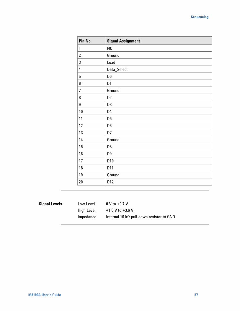
Sequencing
M8190A User’s Guide 57
Pin No. Signal Assignment
1 NC
2 Ground
3 Load
4 Data_Select
5 D0
6 D1
7 Ground
8 D2
9 D3
10 D4
11 D5
12 D6
13 D7
14 Ground
15 D8
16 D9
17 D10
18 D11
19 Ground
20 D12
Signal Levels Low Level 0 V to +0.7 V
High Level +1.6 V to +3.6 V
Impedance Internal 10 kΩ pull-down resistor to GND
58
Signal Description Data Input
The input data represents an index to the next sequence table entry to be
played by the AWG module. 2^19 sequence table entries are available.
Data_Select
The data select signal controls which part of the 19 bit internal sequencer
index is loaded from the Data_In pins. If Data_Select is 1 only the Data_In bits
5..0 are used to load bits 18..13 of the sequencer index. If Data_Select is 0 the
Data_In bits 12..0 are loaded to internal sequencer index 12..0. To load the full
19 sequence index bits first the upper part needs to be loaded (Data_Select =
1) then the lower part.
Load
A rising edge on the Load signal latches the data present at the Data_In pins
into the respective internal registers. If the Data_Select pin is low the loaded
sequencer index is passed to the sequencer for execution.
Note: In 13 bit mode only the lower part of the sequencer entry address is
modified. Data_Select can be left unconnected (low) in this mode. Only 8 k
entries can be addressed in 13 bit mode vs. 512 k entries in 19 bit mode.
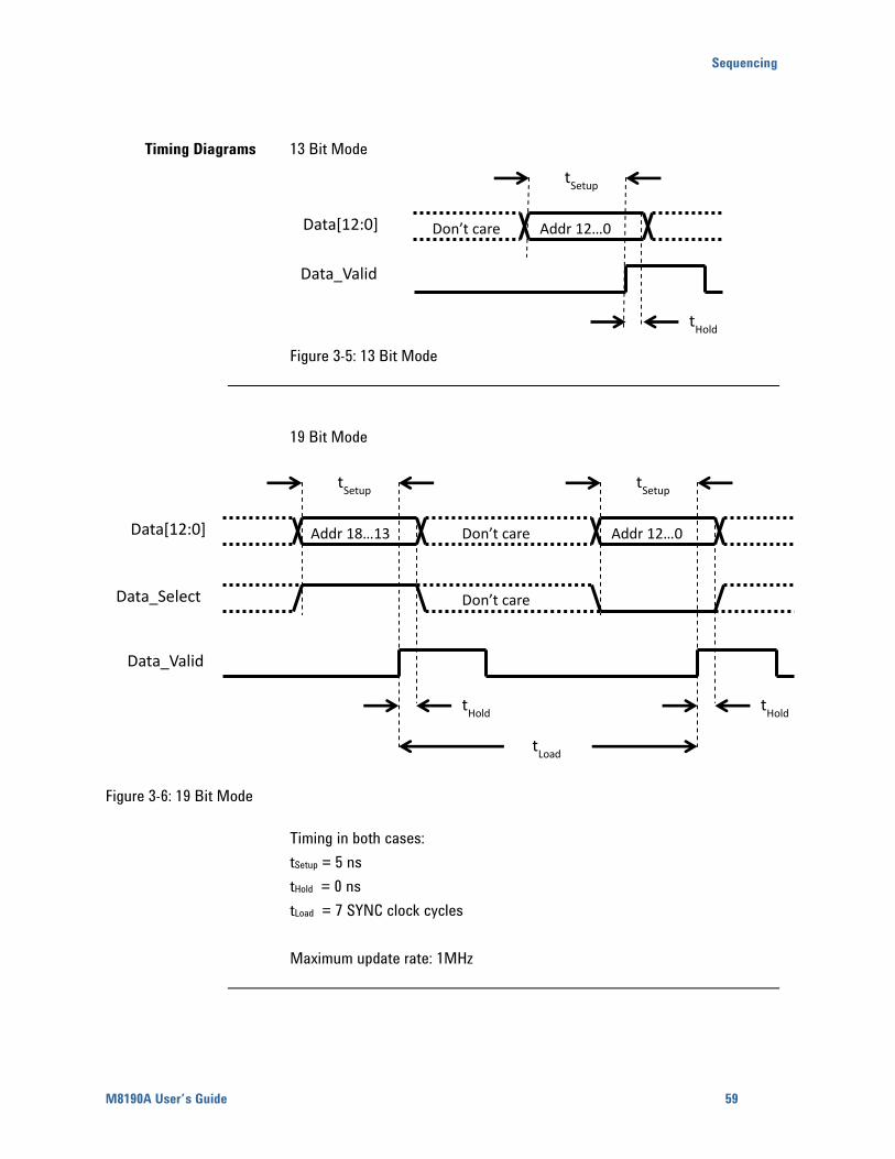
Sequencing
M8190A User’s Guide 59
Timing Diagrams 13 Bit Mode
Figure 3-5: 13 Bit Mode
19 Bit Mode
Figure 3-6: 19 Bit Mode
Timing in both cases:
tSetup = 5 ns
tHold = 0 ns
tLoad = 7 SYNC clock cycles
Maximum update rate: 1MHz
Addr 18…13 Addr 12…0
Don’t care
Don’t care
tHold
tLoad
Data[12:0]
Data_Select
Data_Valid
tSetup
tSetup
tHold
Addr 12…0 Don’t care Data[12:0]
Data_Valid
tSetup
tHold
60
3.6.2 Logical Functions
3.6.2.1 Trigger/Gate/Enable
The trigger, gate and enable signals are used to control the start behavior of
the sequencer, depending on the selected mode. The trigger starts the
sequencer in trigger mode triggered; the gate has the corresponding
functionality (start and stop) in trigger mode gated. The enable is needed in
the armed/auto mode. In this mode the first element is hold in the conditional
advancement mode until enable becomes active. During further loops of the
sequence or scenario, the enable is ignored and the element is executed with
the advancement mode specified in the sequence table. So the enable allows
providing not only an initial offset value, before the real start of the sequencer,
but also an initial segment or sequence.
3.6.2.2 Advancement Event
The advancement event is used to advance within a scenario or sequence.
Responsible for the type of advancement is the selected advancement mode of
the element. The advancement event is stored internally until the sequencer
uses it.
Example:
When receiving an advancement event while executing a conditional segment,
the advancement event is stored until reaching the end of the segment where
the advancement is used. Then the stored advancement event is cleared and
the instrument is able to receive the next one.
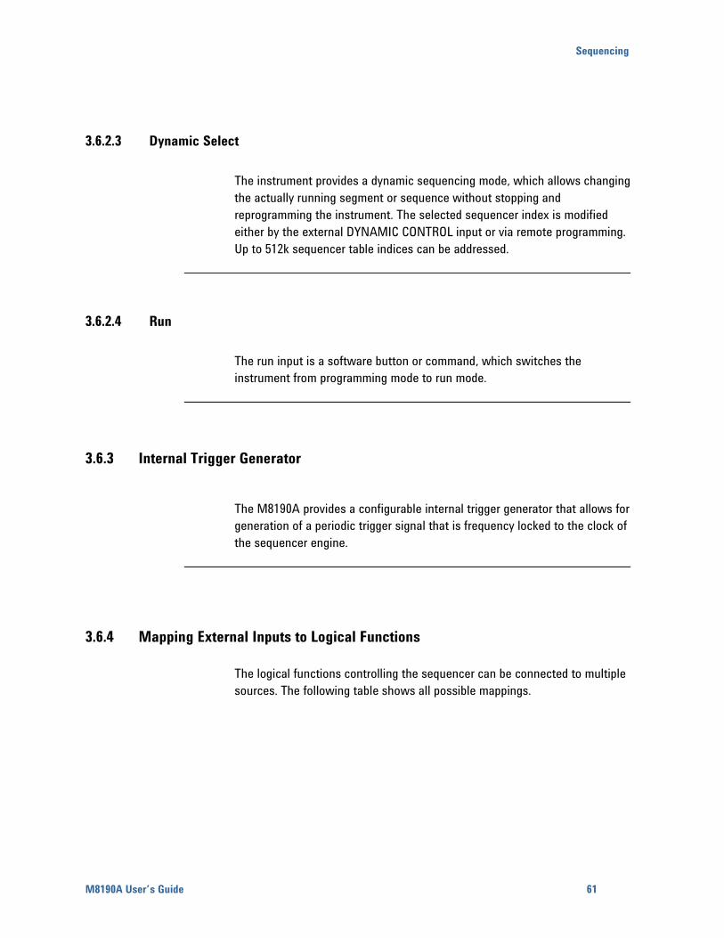
Sequencing
M8190A User’s Guide 61
3.6.2.3 Dynamic Select
The instrument provides a dynamic sequencing mode, which allows changing
the actually running segment or sequence without stopping and
reprogramming the instrument. The selected sequencer index is modified
either by the external DYNAMIC CONTROL input or via remote programming.
Up to 512k sequencer table indices can be addressed.
3.6.2.4 Run
The run input is a software button or command, which switches the
instrument from programming mode to run mode.
3.6.3 Internal Trigger Generator
The M8190A provides a configurable internal trigger generator that allows for
generation of a periodic trigger signal that is frequency locked to the clock of
the sequencer engine.
3.6.4 Mapping External Inputs to Logical Functions
The logical functions controlling the sequencer can be connected to multiple
sources. The following table shows all possible mappings.
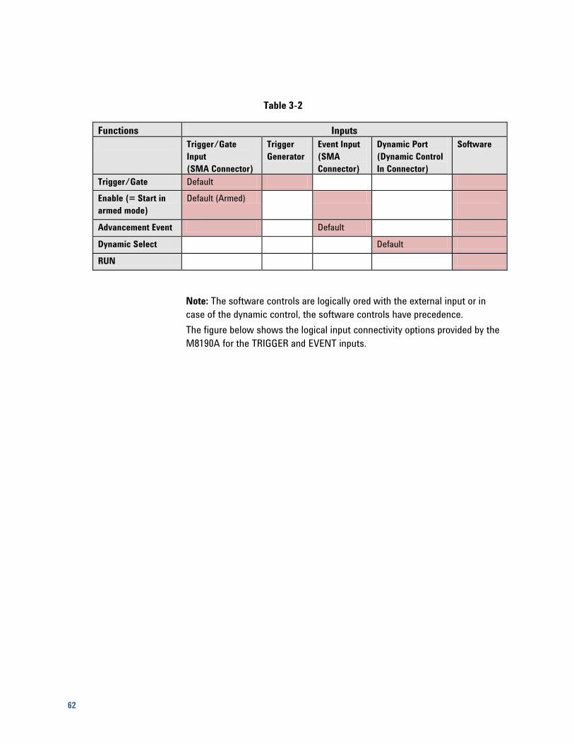
62
Table 3-2
Functions Inputs
Trigger/Gate
Input
(SMA Connector)
Trigger
Generator
Event Input
(SMA
Connector)
Dynamic Port
(Dynamic Control
In Connector)
Software
Trigger/Gate Default
Enable (= Start in
armed mode)
Default (Armed)
Advancement Event Default
Dynamic Select Default
RUN
Note: The software controls are logically ored with the external input or in
case of the dynamic control, the software controls have precedence.
The figure below shows the logical input connectivity options provided by the
M8190A for the TRIGGER and EVENT inputs.
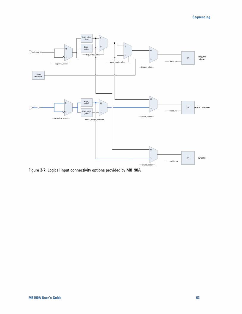
Sequencing
M8190A User’s Guide 63
Event_in
Trigger_in
0
1
enable_select
enable_sw
Enable
Trigger/
Gate
event_sw
Adv. event
0
1
triggen_select
trigger_sw
0
1
trigpolinv_select
evntpolinv_select
0
1
Edge_
detect
Both_edge
_detect
OR
Trigger
Generator
1
0
Edge_
detect
Both_edge
_detect
0
1
OR
evnt_bedge_select
0
1
event_select
0
1
OR
trig_bedge_select
gated_mode_select
Figure 3-7: Logical input connectivity options provided by M8190A
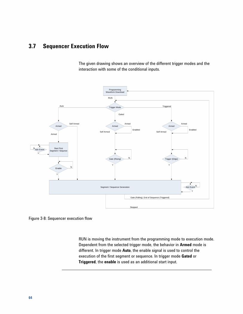
64
3.7 Sequencer Execution Flow
The given drawing shows an overview of the different trigger modes and the
interaction with some of the conditional inputs.
Programming
Waveform Download
Trigger Mode
Armed
Start First
Segment / Sequnce
Armed
Gate (Rising)
Enable
Armed
Self Armed
Y
N
Auto
Gated
Triggered
Y
N
Self Armed
Armed
Enabled
Y
N
Armed
Trigger (Edge)
Self Armed
Armed
Enabled
Y
N
Segment / Sequence Generation
Y
N
Gate (Falling), End of Sequence (Triggered)
Stopped
RUN
Adv Event
Adv Event
Figure 3-8: Sequencer execution flow
RUN is moving the instrument from the programming mode to execution mode.
Dependent from the selected trigger mode, the behavior in Armed mode is
different. In trigger mode Auto, the enable signal is used to control the
execution of the first segment or sequence. In trigger mode Gated or
Triggered, the enable is used as an additional start input.
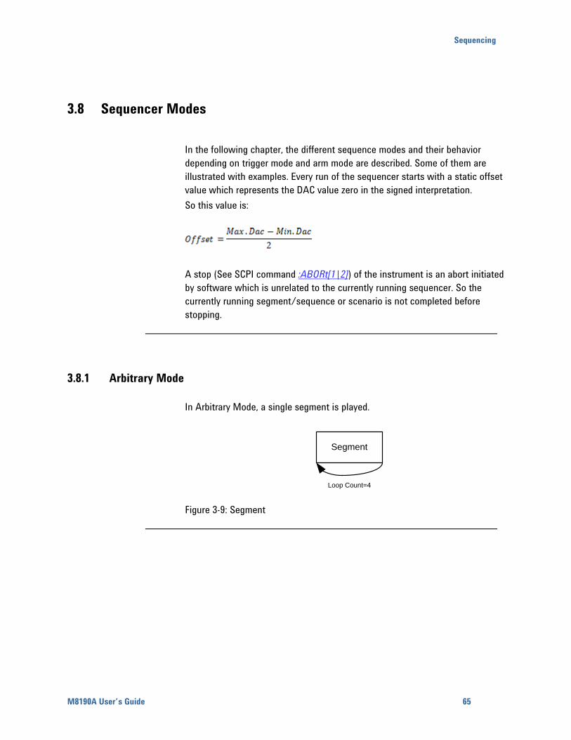
Sequencing
M8190A User’s Guide 65
3.8 Sequencer Modes
In the following chapter, the different sequence modes and their behavior
depending on trigger mode and arm mode are described. Some of them are
illustrated with examples. Every run of the sequencer starts with a static offset
value which represents the DAC value zero in the signed interpretation.
So this value is:
A stop (See SCPI command :ABORt[1|2]) of the instrument is an abort initiated
by software which is unrelated to the currently running sequencer. So the
currently running segment/sequence or scenario is not completed before
stopping.
3.8.1 Arbitrary Mode
In Arbitrary Mode, a single segment is played.
Segment
Loop Count=4
Figure 3-9: Segment
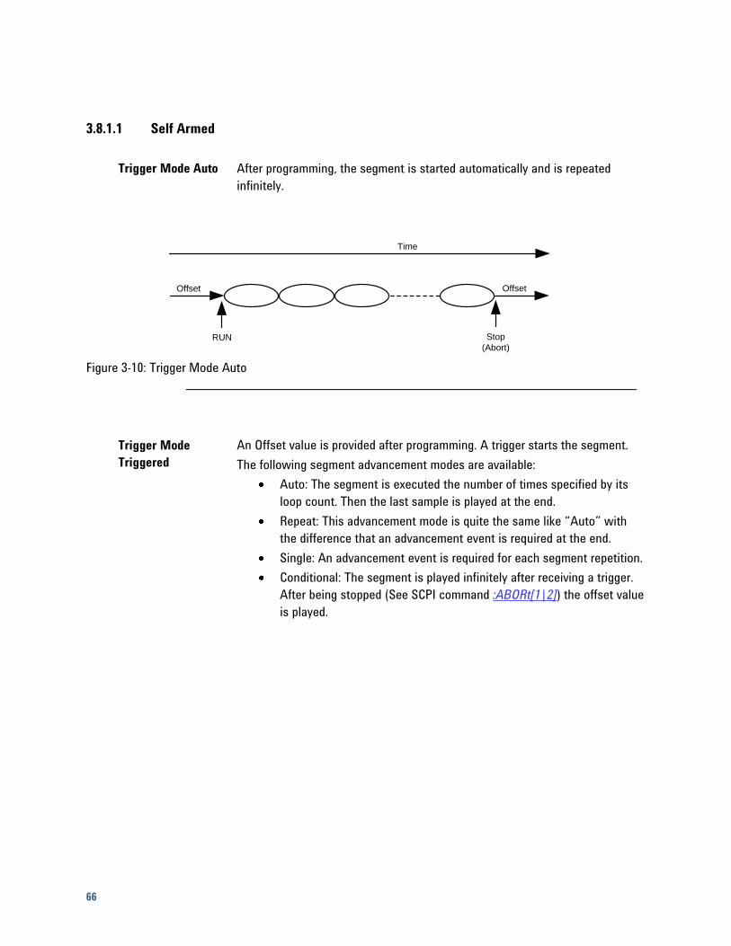
66
3.8.1.1 Self Armed
Trigger Mode Auto After programming, the segment is started automatically and is repeated
infinitely.
Time
Offset
Stop
(Abort)RUN
Offset
Figure 3-10: Trigger Mode Auto
Trigger Mode
Triggered
An Offset value is provided after programming. A trigger starts the segment.
The following segment advancement modes are available:
Auto: The segment is executed the number of times specified by its
loop count. Then the last sample is played at the end.
Repeat: This advancement mode is quite the same like “Auto” with
the difference that an advancement event is required at the end.
Single: An advancement event is required for each segment repetition.
Conditional: The segment is played infinitely after receiving a trigger.
After being stopped (See SCPI command :ABORt[1|2]) the offset value
is played.
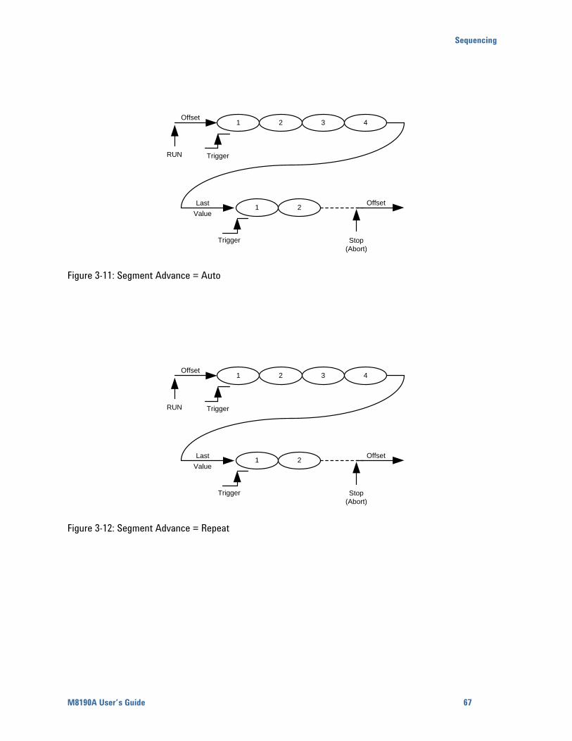
Sequencing
M8190A User’s Guide 67
RUN Trigger
Trigger Stop
(Abort)
Offset
OffsetLast
Value
21 3 4
1 2
Figure 3-11: Segment Advance = Auto
RUN Trigger
Trigger Stop
(Abort)
Offset
OffsetLast
Value
21 3 4
1 2
Figure 3-12: Segment Advance = Repeat
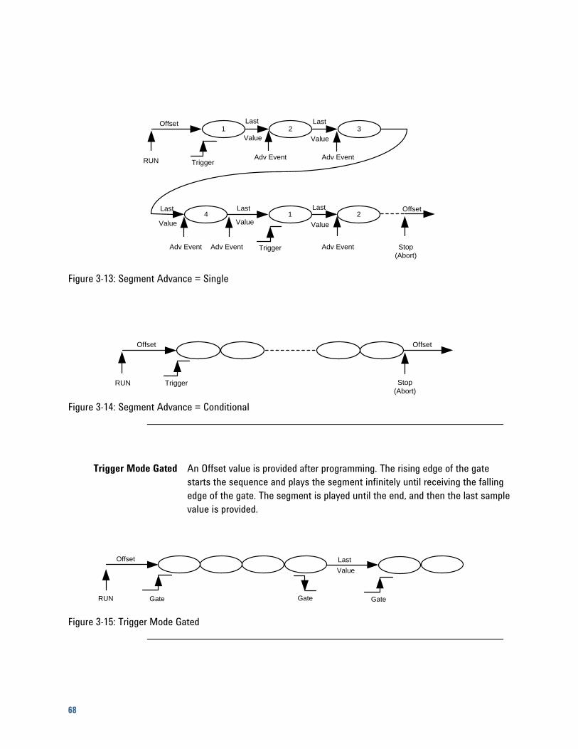
68
RUN Trigger
Trigger Stop
(Abort)
Adv Event Adv Event
Offset
Offset
LastLast
Last Last Last
Value
1
214
32
Value Value
Value Value
Adv Event Adv Event Adv Event
Figure 3-13: Segment Advance = Single
Trigger Stop
(Abort)
Offset Offset
RUN
Figure 3-14: Segment Advance = Conditional
Trigger Mode Gated An Offset value is provided after programming. The rising edge of the gate
starts the sequence and plays the segment infinitely until receiving the falling
edge of the gate. The segment is played until the end, and then the last sample
value is provided.
Offset Last
Value
Gate GateGateRUN
Figure 3-15: Trigger Mode Gated
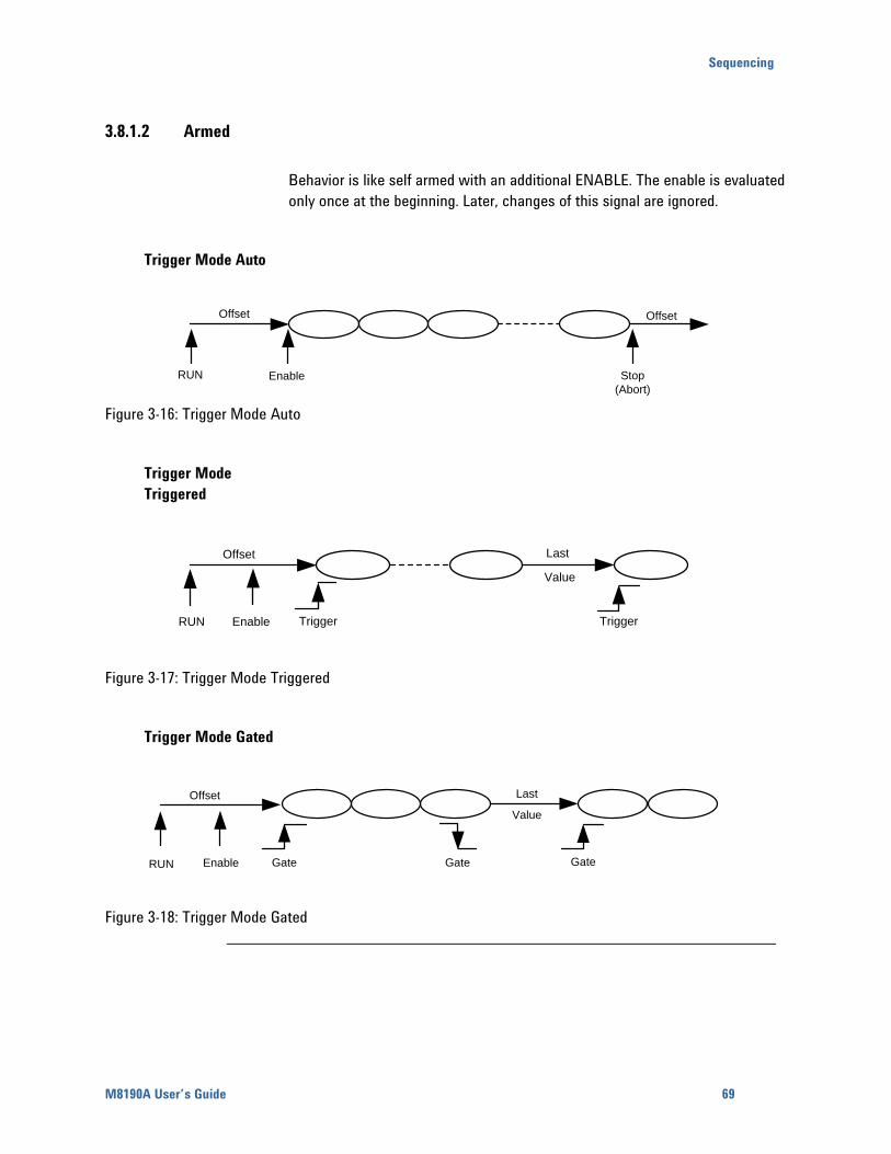
Sequencing
M8190A User’s Guide 69
3.8.1.2 Armed
Behavior is like self armed with an additional ENABLE. The enable is evaluated
only once at the beginning. Later, changes of this signal are ignored.
Trigger Mode Auto
Offset
RUN
Offset
Stop
(Abort)Enable
Figure 3-16: Trigger Mode Auto
Trigger Mode
Triggered
Offset
Trigger Trigger
Last
Value
RUN Enable
Figure 3-17: Trigger Mode Triggered
Trigger Mode Gated
Gate
Last
Value
Gate
Offset
GateRUN Enable
Figure 3-18: Trigger Mode Gated
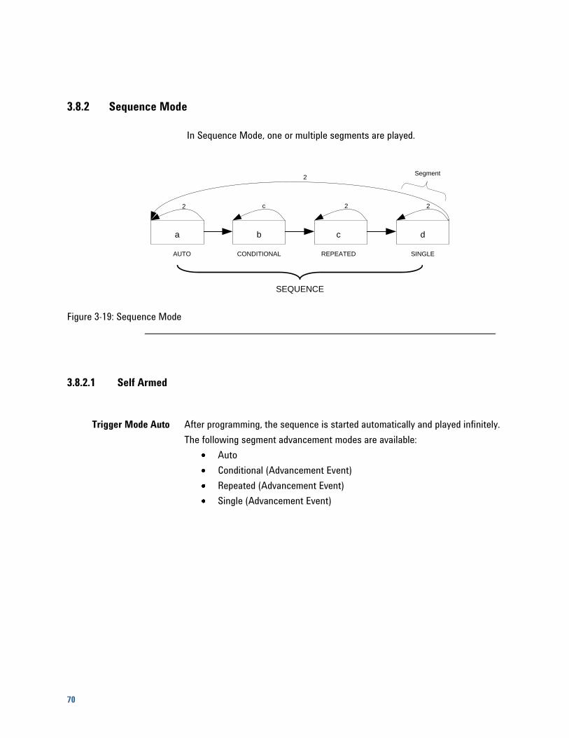
70
3.8.2 Sequence Mode
In Sequence Mode, one or multiple segments are played.
a b c d
AUTO CONDITIONAL REPEATED SINGLE
SEQUENCE
Segment
2 c 2
2
2
Figure 3-19: Sequence Mode
3.8.2.1 Self Armed
Trigger Mode Auto After programming, the sequence is started automatically and played infinitely.
The following segment advancement modes are available:
Auto
Conditional (Advancement Event)
Repeated (Advancement Event)
Single (Advancement Event)
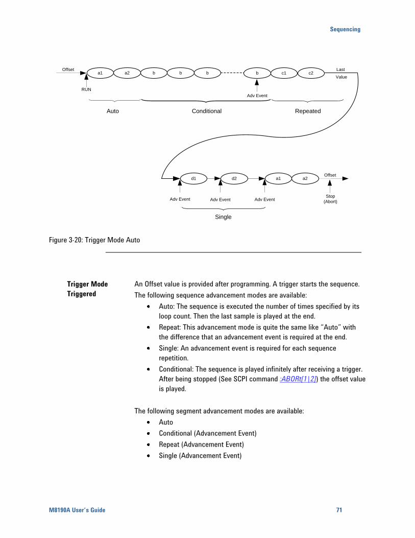
Sequencing
M8190A User’s Guide 71
bb bOffset
RUN
Adv Event
Adv Event Adv Event Adv EventStop
(Abort)
Offset
a1a2
Auto Conditional Repeated
Single
Last
Valuea1 bba2 b c2c1b
a2a1d2d1
Figure 3-20: Trigger Mode Auto
Trigger Mode
Triggered
An Offset value is provided after programming. A trigger starts the sequence.
The following sequence advancement modes are available:
Auto: The sequence is executed the number of times specified by its
loop count. Then the last sample is played at the end.
Repeat: This advancement mode is quite the same like “Auto” with
the difference that an advancement event is required at the end.
Single: An advancement event is required for each sequence
repetition.
Conditional: The sequence is played infinitely after receiving a trigger.
After being stopped (See SCPI command :ABORt[1|2]) the offset value
is played.
The following segment advancement modes are available:
Auto
Conditional (Advancement Event)
Repeat (Advancement Event)
Single (Advancement Event)
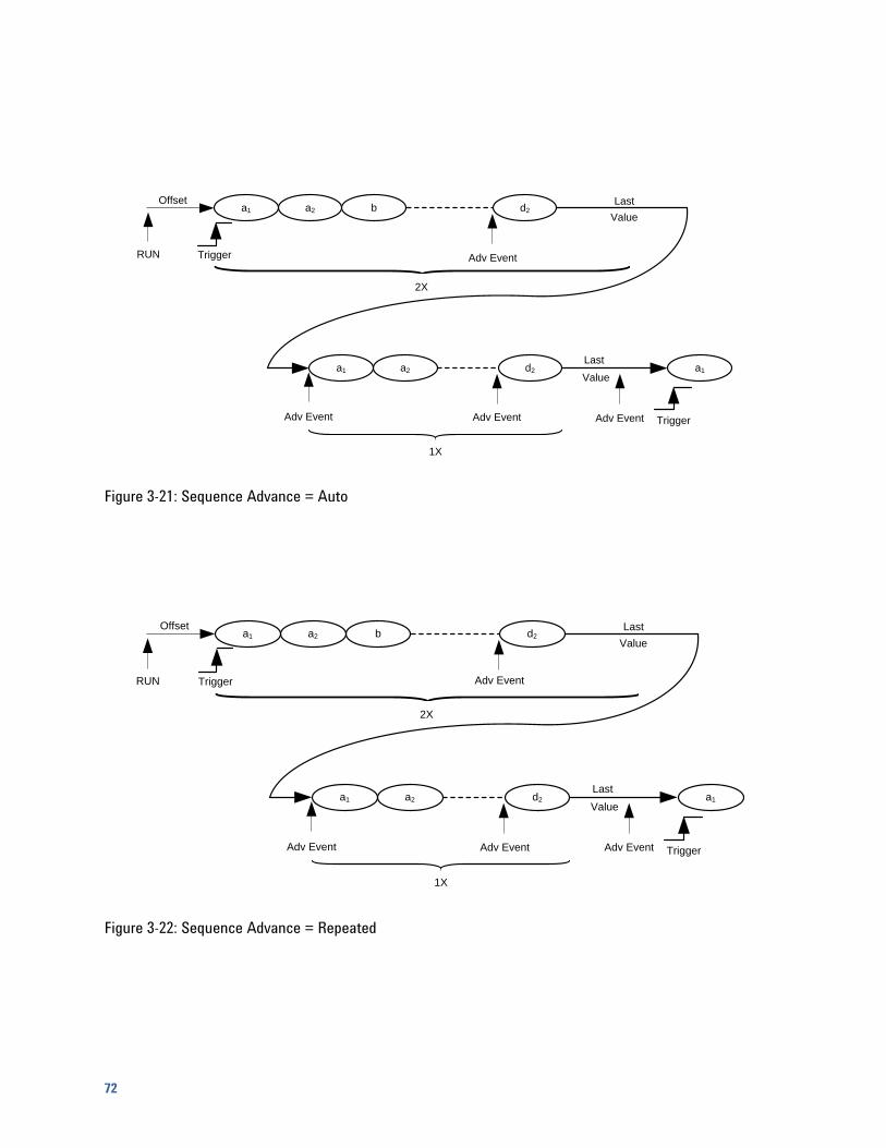
72
bOffset
RUN
a1a2
Adv Event
Trigger
Trigger
Last
Value
Last
Value
2X
1X
ba2a1
a2a1
d2
a1d2
Adv Event Adv Event Adv Event
Figure 3-21: Sequence Advance = Auto
bOffset
RUN
a1a2
Adv Event
Trigger
Trigger
Last
Value
Last
Value
2X
1X
ba2a1
a2a1
d2
a1d2
Adv Event Adv Event Adv Event
Figure 3-22: Sequence Advance = Repeated
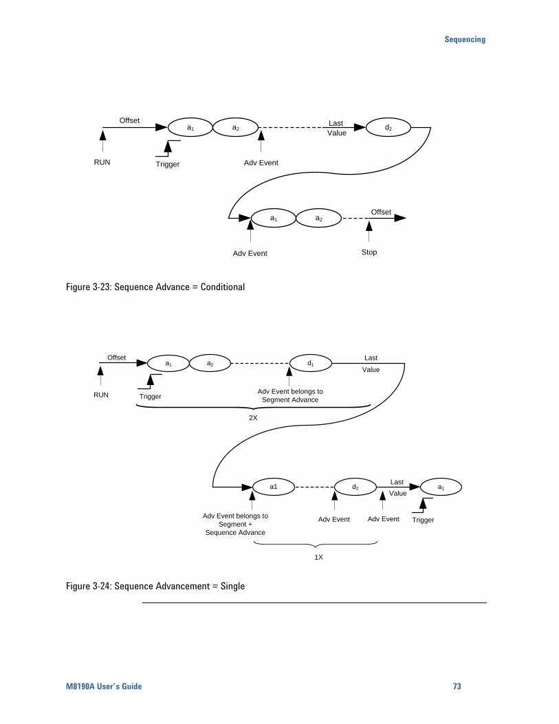
Sequencing
M8190A User’s Guide 73
Offset
RUN Trigger
Stop
Offset
Last
Valuea1
a1
d2a2
a2
Adv Event
Adv Event
Figure 3-23: Sequence Advance = Conditional
Offset
RUN Trigger
Last
Value
Adv Event belongs to
Segment Advance
Adv Event belongs to
Segment +
Sequence Advance
Trigger
Last
Value
2X
1X
a1 a2 d1
a1 d2 a1
Adv Event Adv Event
Figure 3-24: Sequence Advancement = Single
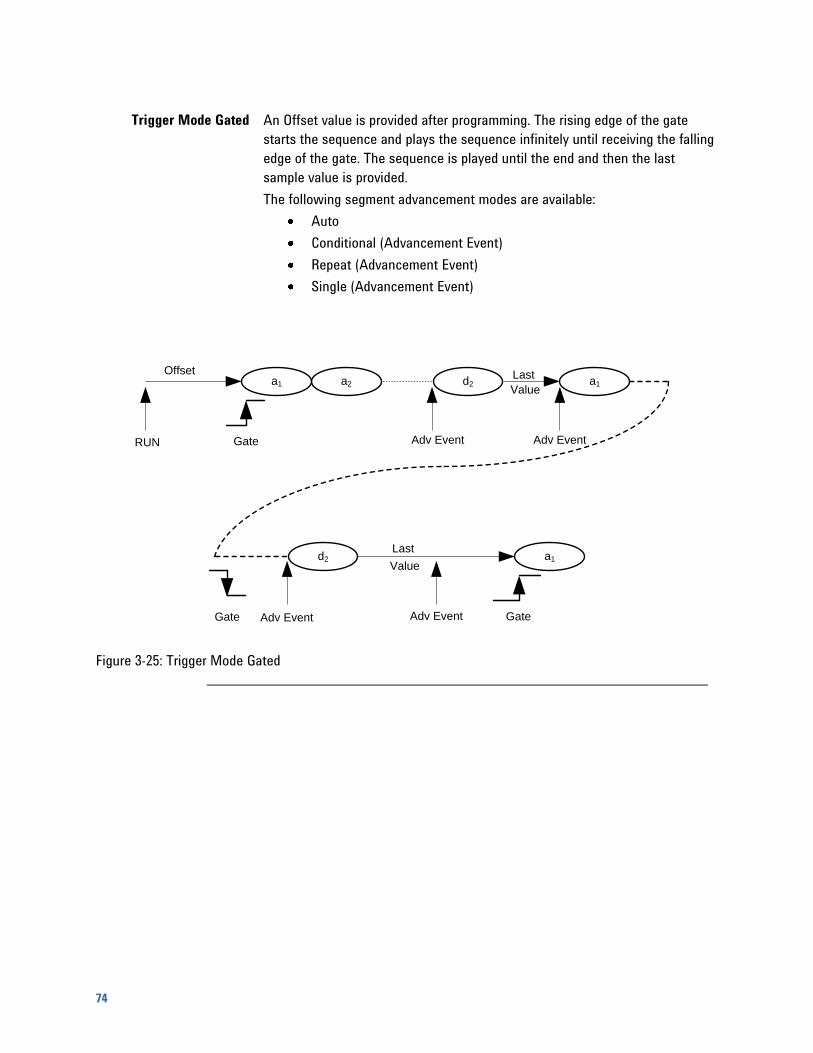
74
Trigger Mode Gated An Offset value is provided after programming. The rising edge of the gate
starts the sequence and plays the sequence infinitely until receiving the falling
edge of the gate. The sequence is played until the end and then the last
sample value is provided.
The following segment advancement modes are available:
Auto
Conditional (Advancement Event)
Repeat (Advancement Event)
Single (Advancement Event)
RUN Gate Adv Event Adv Event
Adv Event Adv EventGate Gate
Offset Last
Valuea1
a1d2
a1d2a2a1
Last
Value
Figure 3-25: Trigger Mode Gated
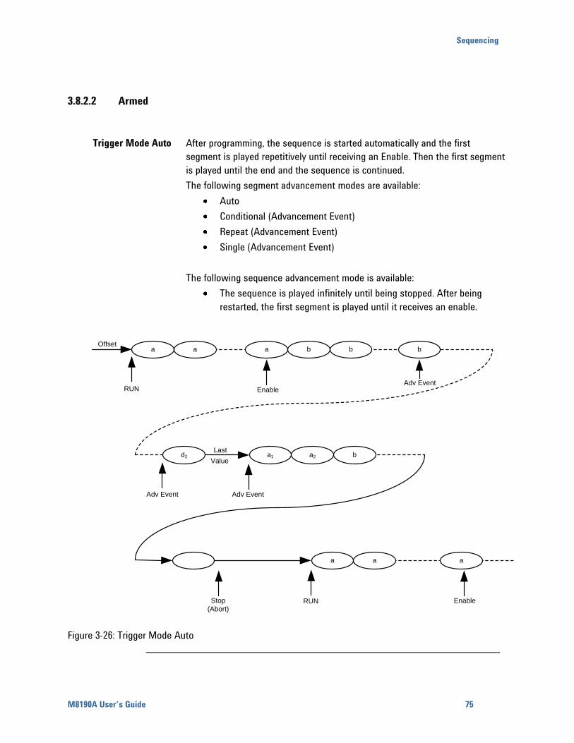
Sequencing
M8190A User’s Guide 75
3.8.2.2 Armed
Trigger Mode Auto After programming, the sequence is started automatically and the first
segment is played repetitively until receiving an Enable. Then the first segment
is played until the end and the sequence is continued.
The following segment advancement modes are available:
Auto
Conditional (Advancement Event)
Repeat (Advancement Event)
Single (Advancement Event)
The following sequence advancement mode is available:
The sequence is played infinitely until being stopped. After being
restarted, the first segment is played until it receives an enable.
RUN EnableAdv Event
Stop
(Abort)
Enable
Adv Event Adv Event
RUN
Offset
d2
aaa
a1
bbbaaa
a2 bLast
Value
Figure 3-26: Trigger Mode Auto
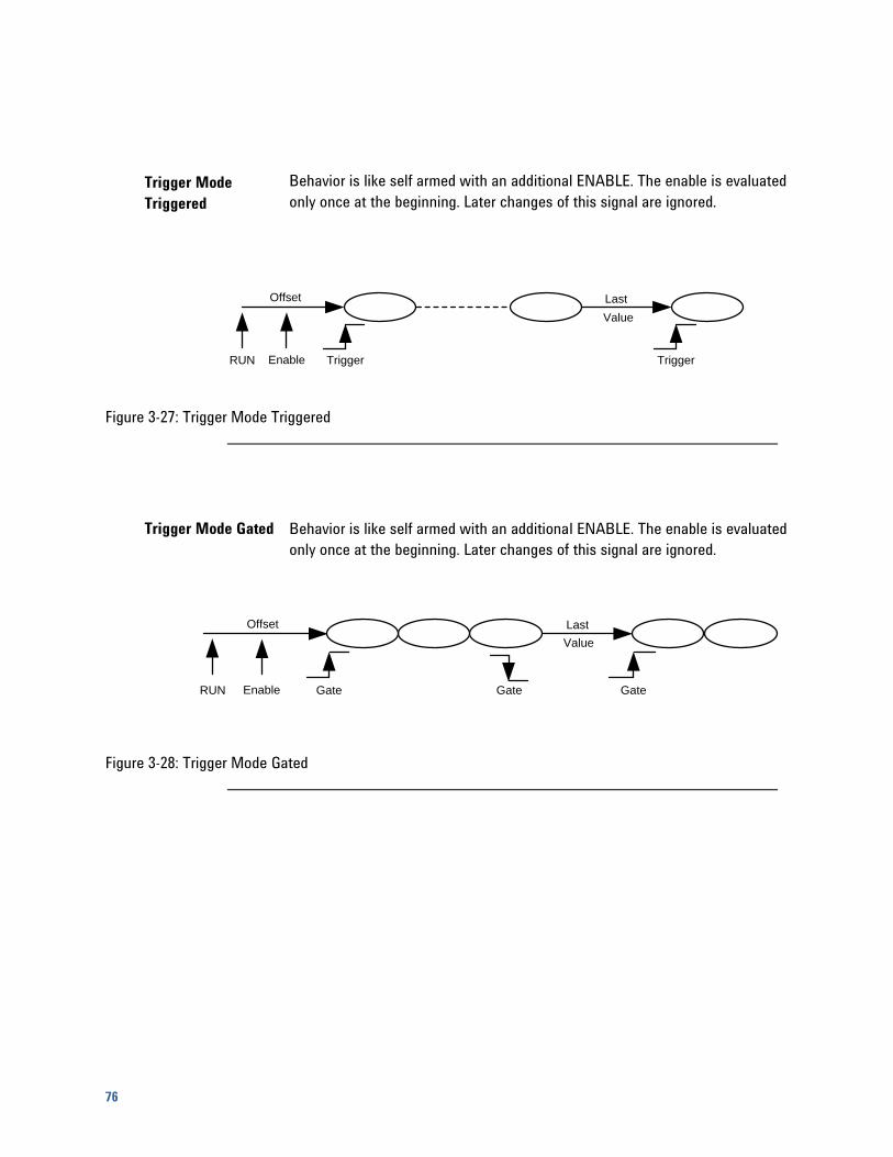
76
Trigger Mode
Triggered
Behavior is like self armed with an additional ENABLE. The enable is evaluated
only once at the beginning. Later changes of this signal are ignored.
Offset
RUN Enable Trigger Trigger
Last
Value
Figure 3-27: Trigger Mode Triggered
Trigger Mode Gated Behavior is like self armed with an additional ENABLE. The enable is evaluated
only once at the beginning. Later changes of this signal are ignored.
Offset
RUN Enable Gate Gate
Last
Value
Gate
Figure 3-28: Trigger Mode Gated
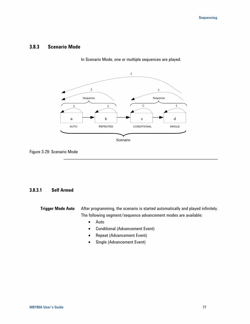
Sequencing
M8190A User’s Guide 77
3.8.3 Scenario Mode
In Scenario Mode, one or multiple sequences are played.
a b c d
AUTO CONDITIONALREPEATED SINGLE
Scenario
Sequence
Sequence
2 2 2C
2 2
2
Figure 3-29: Scenario Mode
3.8.3.1 Self Armed
Trigger Mode Auto After programming, the scenario is started automatically and played infinitely.
The following segment/sequence advancement modes are available:
Auto
Conditional (Advancement Event)
Repeat (Advancement Event)
Single (Advancement Event)
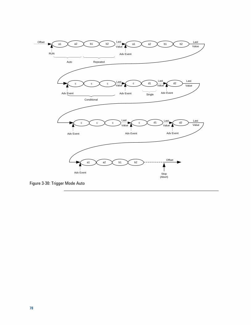
78
bOffset
RUN
a1a2
Auto
Conditional
Single
a1 b2b1a2
Adv Event
Last
Valueba1
a2a1 b2b1a2
Adv Event
Value
ba2 ccc
Adv Event
Value
Last
Lastbd1c
Adv Event
d2Last
Value
Adv Event
ba2 ccc
Adv Event
Value
Lastbd1c
Adv Event
d2Last
Value
Value
Last
ba1a2a1 b2b1a2
Last
Value
Adv Event
Offset
Stop
(Abort)
Repeated
Figure 3-30: Trigger Mode Auto
Sequencing
M8190A User’s Guide 79
Trigger Mode
Triggered
An Offset value is provided after programming. A trigger starts the scenario.
The following scenario advancement modes are available:
Auto: The scenario is executed the number of times specified by its
loop count. Then the last sample is played at the end.
Repeat: This advancement mode is quite the same like “Auto” with
the difference that an advancement event is required at the end.
Single: An advancement event is required for each scenario repetition.
Conditional: The scenario is played infinitely after receiving a trigger.
After being stopped (See SCPI command :ABORt[1|2]) the offset value
is played.
The following segment/sequence advancement modes are available:
Auto
Conditional (Advancement Event)
Repeat (Advancement Event)
Single (Advancement Event)
Trigger Mode Gated An Offset value is provided after programming. The rising edge of the gate
starts the scenario and plays the scenario infinitely until receiving the falling
edge of the gate. The scenario is played until the end and then the last sample
value is provided.
The following segment/sequence advancement modes are available:
Auto
Conditional (Advancement Event)
Repeat (Advancement Event)
Single (Advancement Event)
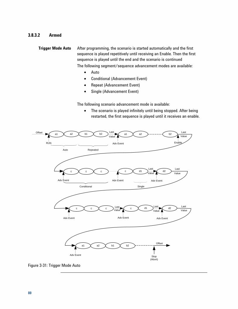
80
3.8.3.2 Armed
Trigger Mode Auto After programming, the scenario is started automatically and the first
sequence is played repetitively until receiving an Enable. Then the first
sequence is played until the end and the scenario is continued
The following segment/sequence advancement modes are available:
Auto
Conditional (Advancement Event)
Repeat (Advancement Event)
Single (Advancement Event)
The following scenario advancement mode is available:
The scenario is played infinitely until being stopped. After being
restarted, the first sequence is played until it receives an enable.
bOffset
RUN
a1a2
Auto
Conditional Single
a1 b2b1a2
Adv Event
Last
Valueba1
a2a1 b2a2
Adv Event
Value
ba2 ccc
Adv Event
Last
bd1c
Adv Event
d2Last
Value
Adv Event
ba2 ccc
Adv Event
bd1c
Adv Event
d2Last
Value
Value
Last
ba1a2a1 b2b1a2
Last
Value
Adv Event
Offset
Stop
(Abort)
Repeated
Enable
Last
Value
Figure 3-31: Trigger Mode Auto
Sequencing
M8190A User’s Guide 81
Trigger Mode
Triggered
Behavior is like self armed with an additional ENABLE. The enable is evaluated
only once at the beginning. Later changes of this signal are ignored.
Trigger Mode Gated Behavior is like self armed with an additional ENABLE. The enable is evaluated
only once at the beginning. Later changes of this signal are ignored.
3.9 Dynamic Sequencing
Dynamic Sequencing is a way to dynamically select segments/sequences to
be played. The selection can be done by software or by the external dynamic
input port. The time from selecting a new segment/sequence to the time the
change is visible at the output is not specified and is dependent from the
actually played segment’s/sequence’s end relative to arrival of the change
event.
When using dynamic sequencing, the arm mode must be set to self-armed
and all advancement modes must be set to Auto. Additionally, the trigger mode
Gated is not allowed.
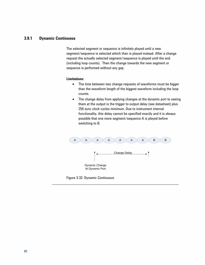
82
3.9.1 Dynamic Continuous
The selected segment or sequence is infinitely played until a new
segment/sequence is selected which then is played instead. After a change
request the actually selected segment/sequence is played until the end
(including loop counts). Then the change towards the new segment or
sequence is performed without any gap.
Limitations:
The time between two change requests of waveforms must be bigger
than the waveform length of the biggest waveform including the loop
counts.
The change delay from applying changes at the dynamic port to seeing
them at the output is the trigger to output delay (see datasheet) plus
256 sync clock cycles minimum. Due to instrument internal
functionality, this delay cannot be specified exactly and it is always
possible that one more segment/sequence A is played before
switching to B.
A AAAA BBAA
Dynamic Change
At Dynamic Port
Change Delay
Figure 3-32: Dynamic Continuous
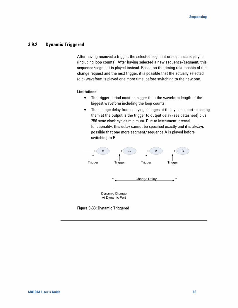
Sequencing
M8190A User’s Guide 83
3.9.2 Dynamic Triggered
After having received a trigger, the selected segment or sequence is played
(including loop counts). After having selected a new sequence/segment, this
sequence/segment is played instead. Based on the timing relationship of the
change request and the next trigger, it is possible that the actually selected
(old) waveform is played one more time, before switching to the new one.
Limitations:
The trigger period must be bigger than the waveform length of the
biggest waveform including the loop counts.
The change delay from applying changes at the dynamic port to seeing
them at the output is the trigger to output delay (see datasheet) plus
256 sync clock cycles minimum. Due to instrument internal
functionality, this delay cannot be specified exactly and it is always
possible that one more segment/sequence A is played before
switching to B.
AA BA
Dynamic Change
At Dynamic Port
Change Delay
Trigger Trigger Trigger Trigger
Figure 3-33: Dynamic Triggered
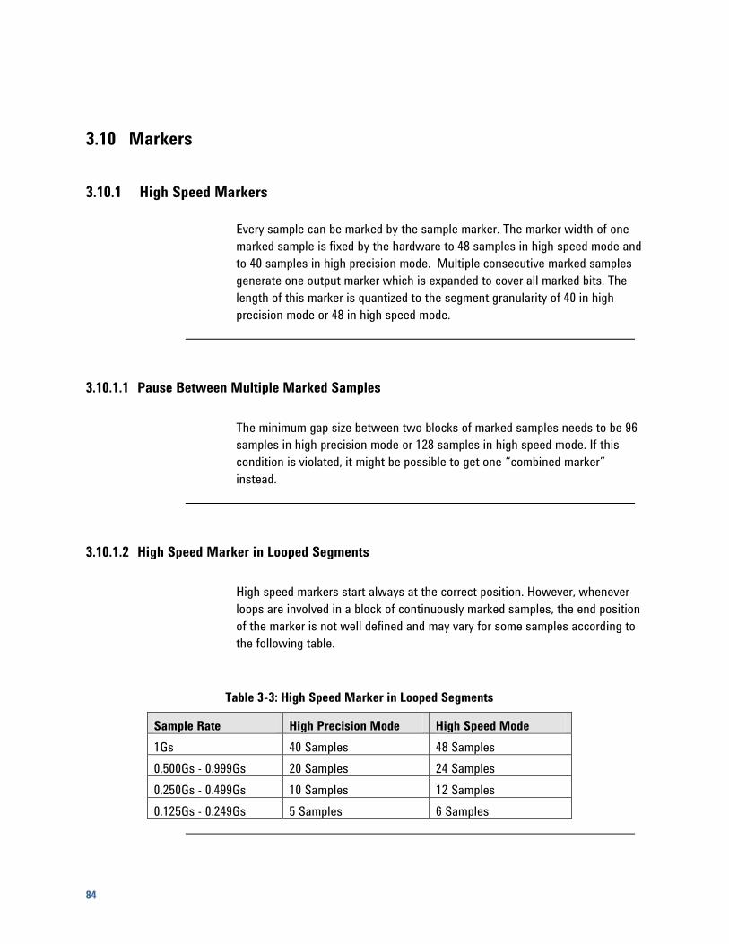
84
3.10 Markers
3.10.1 High Speed Markers
Every sample can be marked by the sample marker. The marker width of one
marked sample is fixed by the hardware to 48 samples in high speed mode and
to 40 samples in high precision mode. Multiple consecutive marked samples
generate one output marker which is expanded to cover all marked bits. The
length of this marker is quantized to the segment granularity of 40 in high
precision mode or 48 in high speed mode.
3.10.1.1 Pause Between Multiple Marked Samples
The minimum gap size between two blocks of marked samples needs to be 96
samples in high precision mode or 128 samples in high speed mode. If this
condition is violated, it might be possible to get one “combined marker”
instead.
3.10.1.2 High Speed Marker in Looped Segments
High speed markers start always at the correct position. However, whenever
loops are involved in a block of continuously marked samples, the end position
of the marker is not well defined and may vary for some samples according to
the following table.
Table 3-3: High Speed Marker in Looped Segments
Sample Rate High Precision Mode High Speed Mode
1Gs 40 Samples 48 Samples
0.500Gs - 0.999Gs 20 Samples 24 Samples
0.250Gs - 0.499Gs 10 Samples 12 Samples
0.125Gs - 0.249Gs 5 Samples 6 Samples
Sequencing
M8190A User’s Guide 85
3.10.1.3 High Speed Marker in Segments which are Addressed Offset Based
The instrument provides a mode where sequence table entries address the
content of segments by offset. Whenever a sequence table entry accesses a
segment with an offset not equal to zero (not starting from the beginning of
the segment), this may result in unexpected sample marker behavior like gaps
when having marked the samples of the data vector referenced by the offset
value.
3.10.2 Sync Markers
Additionally to the high speed marker, each channel provides also a second
marker called sync marker. This sync marker can only be set in sync clock
granularity which is equal to the sample vector granularity.
86
3.11 Idle Command Segments
For some waveform types, like e.g. radar pulses, huge pause segments with a
static output are required between the real waveform segments. The gap
between the real segments should be adjustable in a fine granularity
The idle command segment allows setting a pause between segments in
sample granularity. A minimum length of this pause is required. The idle
command segment is treated as a segment within sequences or scenarios.
There is no segment loop count but a sequence loop counter value is required
for cases where the idle command segment is the first segment of a sequence.
Limitations:
The logic that executes idle command segments uses some elements
which are not in sync clock granularity. To guarantee the trigger to
sample output delay or the advancement event to sample output delay,
these elements need to be reset before accepting new trigger or
advancement events. This requires the waveform generation to be
stopped for at least 3 sync clock cycles before being restarted by a
trigger or an advancement event. A violation of this requirement leads
to an unexpected output behavior for some sync clock cycles.
The sync marker output of the corresponding channel is directly
generated by the sequencer in the sync clock domain and is not
shifted in sample granularity. So some jitter between sample output
and sync marker output might be observed, when using idle command
segments within a sequence or scenario.
Multiple adjacent idle command segments are not allowed. If the
playtime of one idle command segment is not sufficient, the overall
required idle length can be separated into multiple idle command
segments where a normal data segment providing the static idle value
is put in between. Even this wouldn’t be really necessary. One idle
command segment (delay of up to 2^25 sync clock cycles) and one
additional small segment (e.g. length: 10 * segment vectors, loop
count: up to 2^32) would provide an idle delay of more than 200
seconds and should be sufficient for most applications.
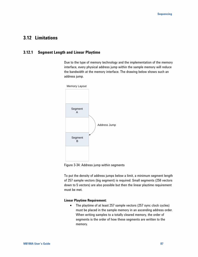
Sequencing
M8190A User’s Guide 87
3.12 Limitations
3.12.1 Segment Length and Linear Playtime
Due to the type of memory technology and the implementation of the memory
interface, every physical address jump within the sample memory will reduce
the bandwidth at the memory interface. The drawing below shows such an
address jump.
Memory Layout
Segment
A
Segment
B
Address Jump
Figure 3-34: Address jump within segments
To put the density of address jumps below a limit, a minimum segment length
of 257 sample vectors (big segment) is required. Small segments (256 vectors
down to 5 vectors) are also possible but then the linear playtime requirement
must be met.
Linear Playtime Requirement:
The playtime of at least 257 sample vectors (257 sync clock cycles)
must be placed in the sample memory in an ascending address order.
When writing samples to a totally cleared memory, the order of
segments is the order of how these segments are written to the
memory.

88
Examples:
One segment with 257 or more sample vectors (big segment)
One segment with 129 vectors and a loop count of 2 (Loop count
multiplies the segment length)
Two segments with 126 and 131 vectors. (Multiple small segments are
combined to meet the requirement)
One segment of 5 vectors and one big segment. (One or multiple small
segments which don’t meet the linear playtime requirement by
themselves, must be located in the memory in front of the next big
segment)
Any small segment with a conditional advancement causes the linear
playtime requirement to be met automatically. The advancement event
to exit the segment is delayed internally until the linear playtime
condition is met. A status register signals any linear playtime violation.
Any small segment with an advancement mode set to repeated or
single causes the linear playtime requirement to be met automatically.
The advancement event is delayed internally until the linear playtime
condition is met. A status register signals any linear playtime violation.
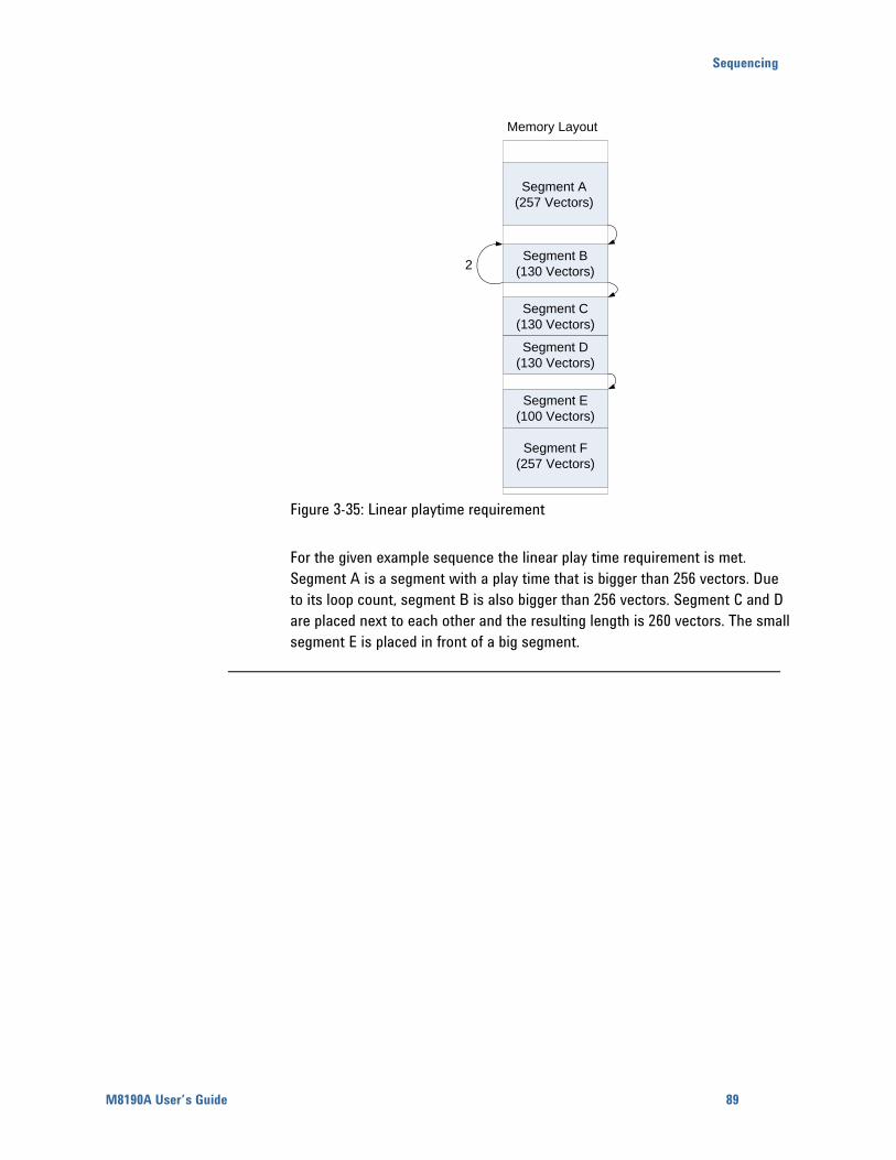
Sequencing
M8190A User’s Guide 89
Memory Layout
Segment A
(257 Vectors)
Segment B
(130 Vectors)
Segment C
(130 Vectors)
Segment D
(130 Vectors)
Segment E
(100 Vectors)
Segment F
(257 Vectors)
2
Figure 3-35: Linear playtime requirement
For the given example sequence the linear play time requirement is met.
Segment A is a segment with a play time that is bigger than 256 vectors. Due
to its loop count, segment B is also bigger than 256 vectors. Segment C and D
are placed next to each other and the resulting length is 260 vectors. The small
segment E is placed in front of a big segment.

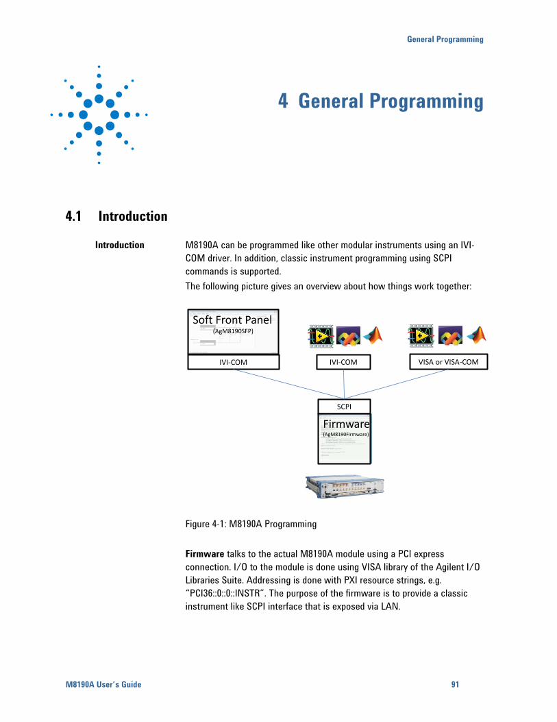
General Programming
M8190A User’s Guide 91
4 General Programming
4.1 Introduction
Introduction M8190A can be programmed like other modular instruments using an IVI-
COM driver. In addition, classic instrument programming using SCPI
commands is supported.
The following picture gives an overview about how things work together:
SCPI
IVI-COM IVI-COM VISA or VISA-COM
Soft Front Panel(AgM8190SFP)
Firmware(AgM8190Firmware)
Figure 4-1: M8190A Programming
Firmware talks to the actual M8190A module using a PCI express
connection. I/O to the module is done using VISA library of the Agilent I/O
Libraries Suite. Addressing is done with PXI resource strings, e.g.
“PCI36::0::0::INSTR”. The purpose of the firmware is to provide a classic
instrument like SCPI interface that is exposed via LAN.
92
IVI-COM wraps the SCPI commands into API based programming model. To
select what Module is programmed, the PXI resource string of the module is
used. The IVI-driver will automatically locate an already running Firmware
that is handling the module. If no such firmware exists, it is started
automatically. This way it is completely hidden that the IVI driver actually
needs the Firmware for programming the M8190A module.
VISA or VISA-COM are libraries from an installed I/O library such as the
Agilent I/O Libraries Suite to program the Firmware “instrument” using SCPI
command strings. Firmware must be already running to connect to it.
Soft Front Panel is providing the user interface. It is used for interactively
changing settings. In addition it can log what IVI calls need to be done when
changing a setting. This can be activated with Tools > Monitor Driver
calls…. Also you can verify changes done from a remote program with
View > Refresh.
4.2 IVI-COM Programming
The recommended way to program the M8190A module is to use the IVI
drivers. See documentation of the IVI drivers how to program using IVI
drivers. The connection between the IVI-COM driver and the
Ag8190Firmware is hidden. To address a module therefore the PXI resource
string of the module, such as “PCI36::0::0::INSTR” is used. The IVI driver will
connect to an already running Ag8190Firmware. If Ag8190Firmware is not
running, it will automatically start it.
General Programming
M8190A User’s Guide 93
4.3 SCPI Programming
Introduction In addition to IVI programming SCPI programming using a LAN connection is
also supported. Three LAN protocols are supported:
VXI-11: The Visa Resource String is e.g. “TCPIP0::localhost::inst0::INSTR”.
HiSLIP: this protocol is recommended. It offers the functionality of VXI-11
protocol with better performance that is near socket performance. Visa
Resource Strings look like “TCPIP0::localhost::hislip0::INSTR”. The correct
resource string is shown in the Ag8190Firmware main window. To use the
HiSlip protocol an I/O library such as the Agilent I/O Libraries Suite must be
installed. Since the protocol is new it might not be supported by the
installed I/O library. The Agilent I/O Libraries Suite 16.1 and above supports
it. However the Agilent I/O Libraries Suite might be installed as secondary
I/O library. In this case check if the primary I/O library supports HiSLIP. If it
does not, the socket protocol must be used.
Socket: this protocol can be used with any I/O library or using standard
operating system socket functionality connecting to port 5025. This protocol
must be used if the used I/O library is not supporting HiSLIP protocol. Visa
Resource string looks like “TCPIP0::localhost::5025::SOCKET”, the exact
resource string can be seen in the Ag8190Firmware main window.
Note: AgM8190Firmare.exe must be started prior to sending SCPI to the
instrument. (See AgM8190Firmware.exe)
4.3.1 AgM8190Firmware.exe
Before sending SCPI commands to the instrument, the firmware
(AgM8190Firmware.exe) must be started. This can be done in the Windows
Start menu (Agilent M8190 M8190) or by starting the Soft Front Panel.
If AgM8190Firmware.exe is started implicitely by using the Soft Front Panel
or IVI Driver, it is minimized to the notification area on the Windows Task
Bar. You can open it to see the VISA Resource String for the different
connection types.
94
4.3.1.1 Command Line Arguments
(See Communication for details about /s, /t, /i, /AutoID, /NoAutoID,
/FallBack).
Table 4-1: Command Line Arguments
Option Description
/Minimized Start minimized.
/Hide Start without application window; only show notify icon.
/s socketPort Set the socket port at which the firmware waits for SCPI commands
/t telnetPort Set the telnet port at which the firmware waits for SCPI commands
/i instrumentNumber Set the instrument number (instN, hislipN) at which the firmware waits
for SCPI commands
/AutoID Automatically select ports and number for the connections (default
behavior).
/NoAutoID Disable the default behavior; i.e. do not automatically select ports and
number for the connections.
/FallBack Try to find unused ports and number if starting a server fails.
/r resourceName Visa PXI resource string of the module to connect to, e.g.
PXI12::0::0::INSTR
4.3.1.2 Communication
Depending on the command line arguments /s, /t, /i, /AutoID, /NoAutoID,
/FallBack, the firmware starts several servers to handle SCPI commands.
(Refer the table above.)
/s, /t, /i: If -1, don’t start the respective servers
Defaults:
Socket port: 5025 (e.g. TCPIP0::localhost::5025::SOCKET)
Telnet port: 5024
HiSLIP, VXI-11.3: 0 (e.g. TCPIP0::localhost::hislip0::INSTR,
TCPIP0::localhost::inst0::INSTR)
General Programming
M8190A User’s Guide 95
/FallBack : If starting a server fails because of a conflict, try using another
port or number
HiSLIP, VXI-11.3: increase the index until a server can be started
successfully
Socket, Telnet: start with the first port not assigned by IANA1 (49152),
then increase it until the servers can be started successfully. If neither
socket nor telnet is disabled the firmware tries to start the servers on
two consecutive ports
(socket port = telnet port + 1)
/AutoID : Automatically select ports and number for the connections, which
are unique per instrument.
This is the default behavior; it is not necessary to specify this argument
on the command line.
If only one M8190 module is available, first try to use the command line
arguments /s, /t, /i or their respective default values if they are not
specified. If starting the servers fails, proceed with the steps below.
/s, /t, /i are ignored (unless they are -1 and a server is disabled)
If the firmware detects more than one M8190 module, use a special
mechanism to obtain a number for the HiSLIP and VXI-11.3 servers,
which makes sure that the firmware uses always the same VISA
resource string per module
The socket and telnet port are then calculated from the HiSLIP index:
telnet port = 49152 + 2 * <HiSLIP index>
socket port = 49152 + 2 * <HiSLIP index> + 1
/NoAutoID : Do not automatically select ports and number for the
connections, use the values specified with /s, /t, /i or their respective
default values instead.
If both /NoAutoID and /AutoID are specified, /AutoID overrides /NoAutoID.
1 Internet Assigned Numbers Authority, http://www.iana.org
96
4.4 Programming Recommendations
This section lists some recommendations for programming the instrument.
Start programming from the default setting. The common command for
setting the default setting is:
Use the binary data format when transferring waveform data.
The SCPI standard defines a long and a short form of the commands. For
fast programming speed it is recommended to use the short forms. The
short forms of the commands are represented by upper case letters. For
example the short form of the command to set 10mV offset is:
To improve programming speed it is also allowed to skip optional subsystem
command parts. Optional subsystem command parts are depicted in square
brackets, e.g.: Set amplitude
Sufficient to use:
M81190A is a real 2 channel instrument. Parameters have to be specified for
output 1 and output 2. If there is no output specified the command will set
the default output 1. So, for setting a offset of 10mV for output 1 and output
2 the commands are:
# sets offset of 10mV at output 1
# sets offset of 10mV at output 1
# sets offset of 10mV at output 2
If it is important to know whether the last command is completed then send
the common query:
It is recommended to test the new setting which will be programmed on the
instrument by setting it up manually. When you have found the correct
setting, then use this to create the program.
In the program it is recommended to send the command for starting data
generation ( ) as the last command. This way intermediate
stop/restarts (e.g. when changing sample rate or loading a waveform) are
avoided and optimum execution performance is achieved.
# set default settings
# other commands to set modes
# and parameters
# enable the output 1
# start data generation.
General Programming
M8190A User’s Guide 97
4.5 System Related Commands (SYSTem Subsystem)
4.5.1 SYSTem:ERRor[:NEXT]?
Read and clear one error from the instrument’s error queue.
A record of up to 30 command syntax or hardware errors can be stored in
the error queue. Errors are retrieved in first-in-first-out (FIFO) order. The first
error returned is the first error that was stored. Errors are cleared as you
read them.
If more than 30 errors have occurred, the last error stored in the queue (the
most recent error) is replaced with “Queue overflow”. No additional errors
are stored until you remove errors from the queue.
If no errors have occurred when you read the error queue, the instrument
responds with 0,“No error”.
The error queue is cleared by the command, when the power is
cycled, or when the firmware is re-started.
The error queue is not cleared by a reset ( ) command.
The error messages have the following format (the error string may contain
up to 255 characters):
error number,”Description”, e.g.
-113,”Undefined header”.
4.5.2 SYSTem:HELP:HEADers?
The HEADers? query returns all SCPI commands and queries and IEEE 488.2
common commands and common queries implemented by the instrument.
The response is a <DEFINITE LENGTH ARBITRARY BLOCK RESPONSE
DATA> element. The full path for every command and query is returned
separated by linefeeds. The syntax of the response is defined as: The
<nonzero digit> and sequence of <digit> follow the rules in IEEE 488.2,
Section 8.7.9. An <SCPI header> is defined as: It contains all the nodes from
the root. The <SCPI program mnemonic> contains the node in standard
SCPI format. The short form uses uppercase characters while the additional
characters for the long form are in lowercase characters. Default nodes are
surrounded by square brackets ([]).
98
4.5.3 :SYSTem:LICense:EXTended:LIST?
Lists the licenses installed.
4.5.4 :SYSTem:SET[?]
In query form, the command reads a block of data containing the
instrument’s complete set-up. The set-up information includes all parameter
and mode settings, but does not include the contents of the instrument
setting memories or the status group registers. The data is in a binary
format, not ASCII, and cannot be edited.
In set form, the block data must be a complete instrument set-up read using
the query form of the command.
This command has the same functionality as the command.
4.6 Common Command List
4.6.1 *IDN?
Read the instrument’s identification string which contains four fields
separated by commas. The first field is the manufacturer’s name, the second
field is the model number, the third field is the serial number, and the fourth
field is a revision code which contains four numbers separated dots and a
fifth number separated by a dash:
Agilent Technologies, M8190A,<serial number>, x.x.x.x-h
x.x.x.x= Firmware revision number, e.g. 2.0.0.0
h= Hardware revision number
4.6.2 *CLS
Clear the event register in all register groups. This command also clears the
error queue and cancels a operation. It doesn’t clear the enable
register.
General Programming
M8190A User’s Guide 99
4.6.3 *ESE
Enable bits in the Standard Event Status Register to be reported in the
Status Byte. The selected bits are summarized in the “Standard Event” bit
(bit 5) of the Status Byte Register. The query returns a value which
corresponds to the binary-weighted sum of all bits enabled decimal by the
command. These bits are not cleared by a command. Value
Range: 0–255.
4.6.4 *ESR?
Query the Standard Event Status Register. Once a bit is set, it remains set
until cleared by a (clear status) command or queried by this
command. A query of this register returns a decimal value which
corresponds to the binary-weighted sum of all bits set in the register.
4.6.5 *OPC
Set the “Operation Complete” bit (bit 0) in the Standard Event register after
the previous commands have been completed.
4.6.6 *OPC?
Return “1” to the output buffer after the previous commands have been
completed. Other commands cannot be executed until this command
completes.
4.6.7 *OPT?
Read the installed options. The response consists of any number of fields
separated by commas.
100
4.6.8 *RST
Reset instrument to its factory default state.
4.6.9 *SRE[?]
Enable bits in the Status Byte to generate a Service Request. To enable
specific bits, you must write a decimal value which corresponds to the
binary-weighted sum of the bits in the register. The selected bits are
summarized in the “Master Summary” bit (bit 6) of the Status Byte Register.
If any of the selected bits change from “0” to “1”, a Service Request signal
is generated. The query returns a decimal value which corresponds
to the binary-weighted sum of all bits enabled by the command.
4.6.10 *STB?
Query the summary (status byte condition) register in this register group.
This command is similar to a Serial Poll but it is processed like any other
instrument command. This command returns the same result as a Serial Poll
but the “Master Summary” bit (bit 6) is not cleared by the
command.
4.6.11 *TST?
Execute Self Tests. If self-tests pass, a 0 is returned. A number lager than 0
indicates the number of failed tests.
To get actual messages, use
4.6.12 *LRN?
Query the instrument and return a binary block of data containing the
current settings (learn string). You can then send the string back to the
instrument to restore this state at a later time. For proper operation, do not
modify the returned string before sending it to the instrument. Use
to send the learn string. See .
General Programming
M8190A User’s Guide 101
4.7 Status Model
Introduction This section describes the structure of the SCPI status system used by the
M8190A. The status system records various conditions and states of the
instrument in several register groups as shown on the following pages. Each
of the register groups is made up of several low level registers called
Condition registers, Event registers, and Enable registers which control the
action of specific bits within the register group.
These groups are explained below:
A condition register continuously monitors the state of the instrument. The
bits in the condition register are updated in real time and the bits are not
latched or buffered. This is a read-only register and bits are not cleared
when you read the register. A query of a condition register returns a decimal
value which corresponds to the binary-weighted sum of all bits set in that
register.
An event register latches the various events from changes in the condition
register. There is no buffering in this register; while an event bit is set,
subsequent events corresponding to that bit are ignored. This is a read only
register. Once a bit is set, it remains set until cleared by query command
(such as ) or a (clear status) command. A
query of this register returns a decimal value which corresponds to the
binary-weighted sum of all bits set in that register.
An enable register defines which bits in the event register will be reported
to the Status Byte register group. You can write to or read from an enable
register. A (clear status) command will not clear the enable register
but it does clear all bits in the event register. A command
clears all bits in the enable register. To enable bits in the enable register to
be reported to the Status Byte register, you must write a decimal value
which corresponds to the binary weighted sum of the corresponding bits.
Transition Filters are used to detect changes of the state in the condition
register and set the corresponding bit in the event register. You can set
transition filter bits to detect positive transitions (PTR), negative transitions
(NTR) or both. Transition filters are read/write registers. They are not
affected by .
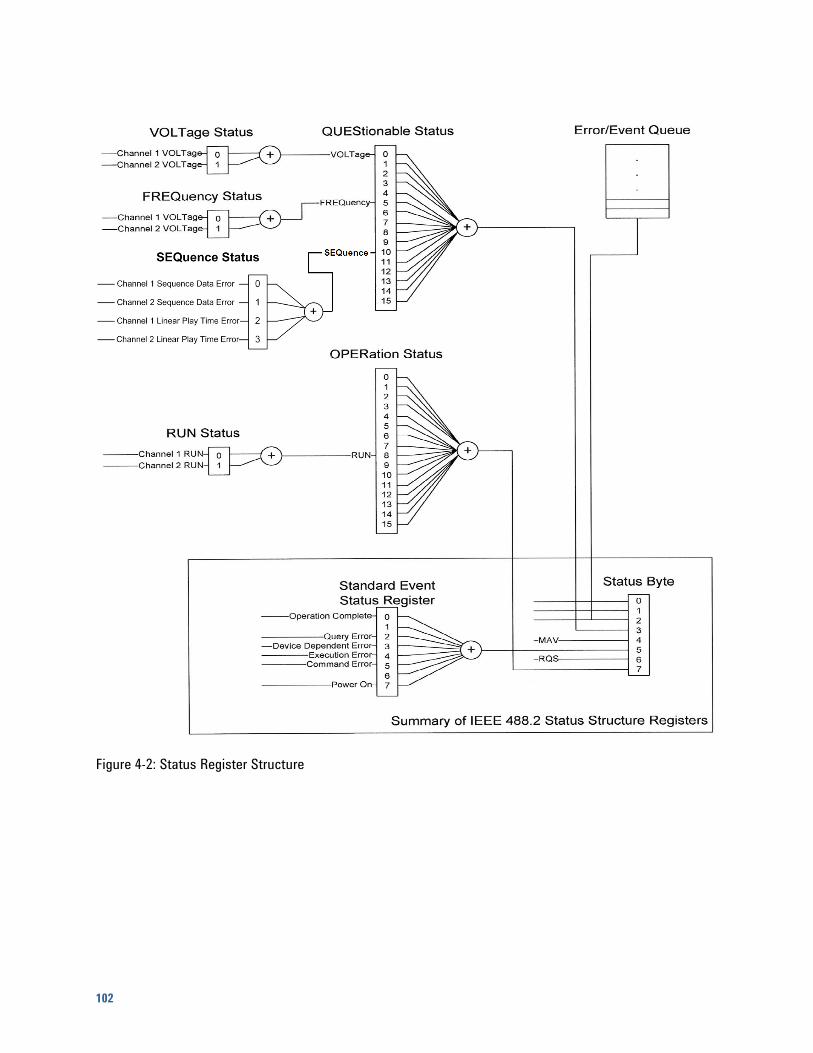
102
Figure 4-2: Status Register Structure
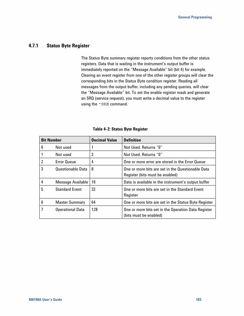
General Programming
M8190A User’s Guide 103
4.7.1 Status Byte Register
The Status Byte summary register reports conditions from the other status
registers. Data that is waiting in the instrument’s output buffer is
immediately reported on the “Message Available” bit (bit 4) for example.
Clearing an event register from one of the other register groups will clear the
corresponding bits in the Status Byte condition register. Reading all
messages from the output buffer, including any pending queries, will clear
the “Message Available” bit. To set the enable register mask and generate
an SRQ (service request), you must write a decimal value to the register
using the command.
Table 4-2: Status Byte Register
Bit Number Decimal Value Definition
0 Not used 1 Not Used. Returns “0”
1 Not used 2 Not Used. Returns “0”
2 Error Queue 4 One or more error are stored in the Error Queue
3 Questionable Data 8 One or more bits are set in the Questionable Data
Register (bits must be enabled)
4 Message Available 16 Data is available in the instrument’s output buffer
5 Standard Event 32 One or more bits are set in the Standard Event
Register
6 Master Summary 64 One or more bits are set in the Status Byte Register
7 Operational Data 128 One or more bits set in the Operation Data Register
(bits must be enabled)
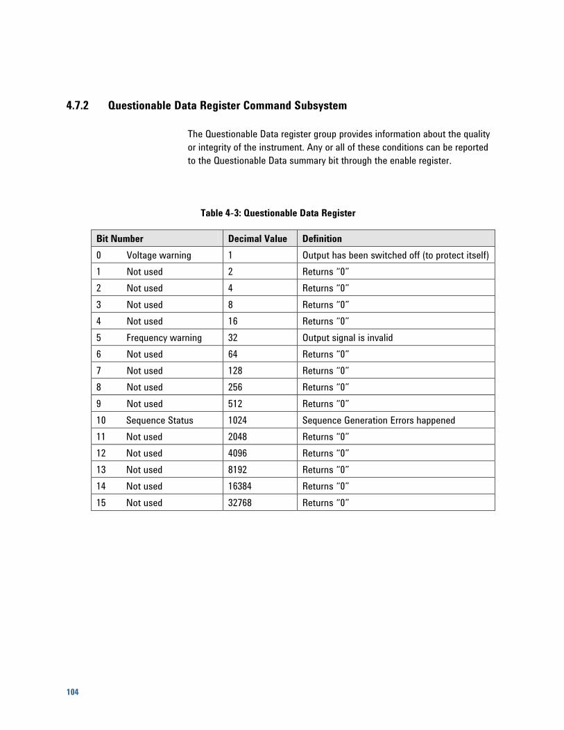
104
4.7.2 Questionable Data Register Command Subsystem
The Questionable Data register group provides information about the quality
or integrity of the instrument. Any or all of these conditions can be reported
to the Questionable Data summary bit through the enable register.
Table 4-3: Questionable Data Register
Bit Number Decimal Value Definition
0 Voltage warning 1 Output has been switched off (to protect itself)
1 Not used 2 Returns “0”
2 Not used 4 Returns “0”
3 Not used 8 Returns “0”
4 Not used 16 Returns “0”
5 Frequency warning 32 Output signal is invalid
6 Not used 64 Returns “0”
7 Not used 128 Returns “0”
8 Not used 256 Returns “0”
9 Not used 512 Returns “0”
10 Sequence Status 1024 Sequence Generation Errors happened
11 Not used 2048 Returns “0”
12 Not used 4096 Returns “0”
13 Not used 8192 Returns “0”
14 Not used 16384 Returns “0”
15 Not used 32768 Returns “0”
General Programming
M8190A User’s Guide 105
The following commands access the questionable status group.
4.7.2.1 :STATus:QUEStionable[:EVENt]?
Reads the event register in the questionable status group. It’s a read-only
register. Once a bit is set, it remains set until cleared by this command or
the command. A query of the register returns a decimal value which
corresponds to the binary-weighted sum of all bits set in the register.
4.7.2.2 :STATus:QUEStionable:CONDition?
Reads the condition register in the questionable status group. It’s a read-
only register and bits are not cleared when you read the register. A query of
the register returns a decimal value which corresponds to the binary-
weighted sum of all bits set in the register.
4.7.2.3 :STATus:QUEStionable:ENABle[?]
Sets or queries the enable register in the questionable status group. The
selected bits are then reported to the Status Byte. A will not clear the
enable register but it does clear all bits in the event register. To enable bits
in the enable register, you must write a decimal value which corresponds to
the binary-weighted sum of the bits you wish to enable in the register.
4.7.2.4 :STATus:QUEStionable:NTRansition[?]
Sets or queries the negative-transition register in the questionable status
group. A negative transition filter allows an event to be reported when a
condition changes from true to false. Setting both positive/negative filters
true allows an event to be reported anytime the condition changes. Clearing
both filters disable event reporting. The contents of transition filters are
unchanged by and .
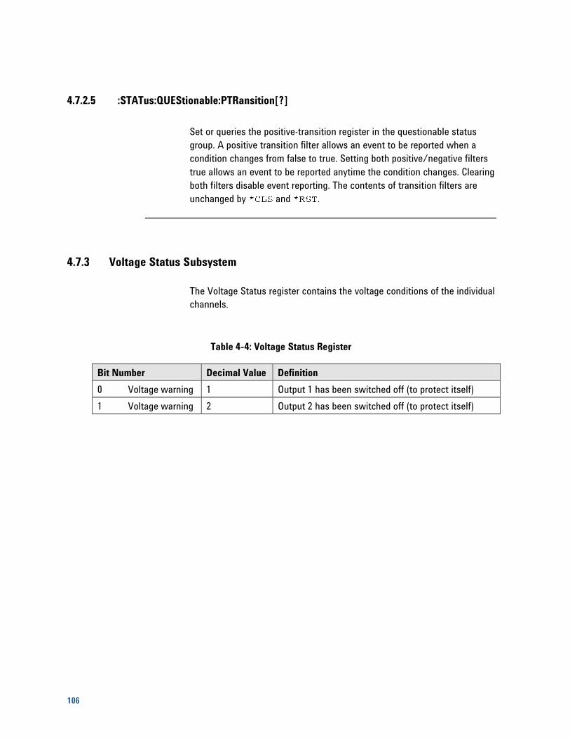
106
4.7.2.5 :STATus:QUEStionable:PTRansition[?]
Set or queries the positive-transition register in the questionable status
group. A positive transition filter allows an event to be reported when a
condition changes from false to true. Setting both positive/negative filters
true allows an event to be reported anytime the condition changes. Clearing
both filters disable event reporting. The contents of transition filters are
unchanged by and .
4.7.3 Voltage Status Subsystem
The Voltage Status register contains the voltage conditions of the individual
channels.
Table 4-4: Voltage Status Register
Bit Number Decimal Value Definition
0 Voltage warning 1 Output 1 has been switched off (to protect itself)
1 Voltage warning 2 Output 2 has been switched off (to protect itself)
General Programming
M8190A User’s Guide 107
The following commands access the voltage status group.
4.7.3.1 :STATus:QUEStionable:VOLTage[:EVENt]?
Reads the event register in the questionable status group. It’s a read-only
register. Once a bit is set, it remains set until cleared by this command or
command. A query of the register returns a decimal value which
corresponds to the binary-weighted sum of all bits set in the register.
4.7.3.2 :STATus:QUEStionable:VOLTage:CONDition?
Reads the condition register in the questionable status group. It’s a read-
only register and bits are not cleared when you read the register. A query of
the register returns a decimal value which corresponds to the binary-
weighted sum of all bits set in the register.
4.7.3.3 :STATus:QUEStionable:VOLTage:ENABle[?]
Sets or queries the enable register in the questionable status group. The
selected bits are then reported to the Status Byte. A will not clear the
enable register but it does clear all bits in the event register. To enable bits
in the enable register, you must write a decimal value which corresponds to
the binary-weighted sum of the bits you wish to enable in the register.
4.7.3.4 :STATus:QUEStionable:VOLTage:NTRansition[?]
Sets or queries the negative-transition register in the questionable status
group. A negative transition filter allows an event to be reported when a
condition changes from true to false. Setting both positive/negative filters
true allows an event to be reported anytime the condition changes. Clearing
both filters disable event reporting. The contents of transition filters are
unchanged by and .
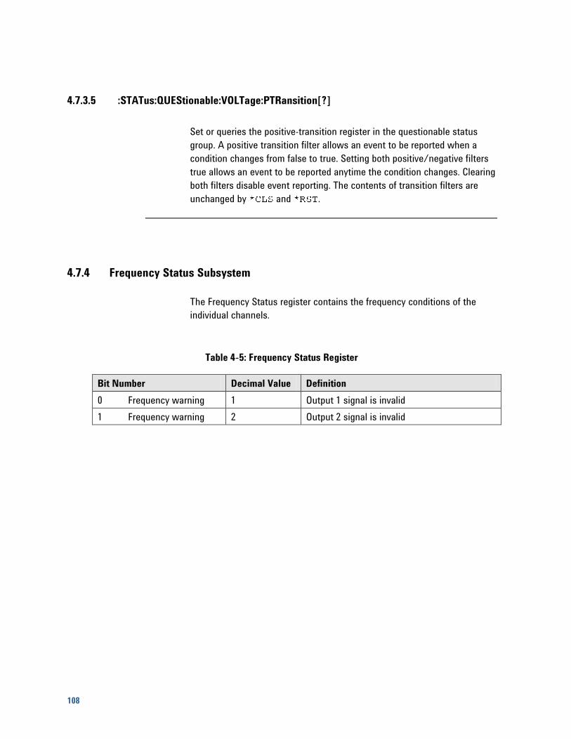
108
4.7.3.5 :STATus:QUEStionable:VOLTage:PTRansition[?]
Set or queries the positive-transition register in the questionable status
group. A positive transition filter allows an event to be reported when a
condition changes from false to true. Setting both positive/negative filters
true allows an event to be reported anytime the condition changes. Clearing
both filters disable event reporting. The contents of transition filters are
unchanged by and .
4.7.4 Frequency Status Subsystem
The Frequency Status register contains the frequency conditions of the
individual channels.
Table 4-5: Frequency Status Register
Bit Number Decimal Value Definition
0 Frequency warning 1 Output 1 signal is invalid
1 Frequency warning 2 Output 2 signal is invalid
General Programming
M8190A User’s Guide 109
The following commands access the frequency status group.
4.7.4.1 :STATus:QUEStionable:FREQuency[:EVENt]?
Reads the event register in the questionable status group. It’s a read-only
register. Once a bit is set, it remains set until cleared by this command or
command. A query of the register returns a decimal value which
corresponds to the binary-weighted sum of all bits set in the register.
4.7.4.2 :STATus:QUEStionable:FREQuency:CONDition?
Reads the condition register in the questionable status group. It’s a read-
only register and bits are not cleared when you read the register. A query of
the register returns a decimal value which corresponds to the binary-
weighted sum of all bits set in the register.
4.7.4.3 :STATus:QUEStionable:FREQuency:ENABle[?]
Sets or queries the enable register in the questionable status group. The
selected bits are then reported to the Status Byte. A will not clear the
enable register but it does clear all bits in the event register. To enable bits
in the enable register, you must write a decimal value which corresponds to
the binary-weighted sum of the bits you wish to enable in the register.
4.7.4.4 :STATus:QUEStionable:FREQuency:NTRansition[?]
Sets or queries the negative-transition register in the questionable status
group. A negative transition filter allows an event to be reported when a
condition changes from true to false. Setting both positive/negative filters
true allows an event to be reported anytime the condition changes. Clearing
both filters disable event reporting. The contents of transition filters are
unchanged by and .
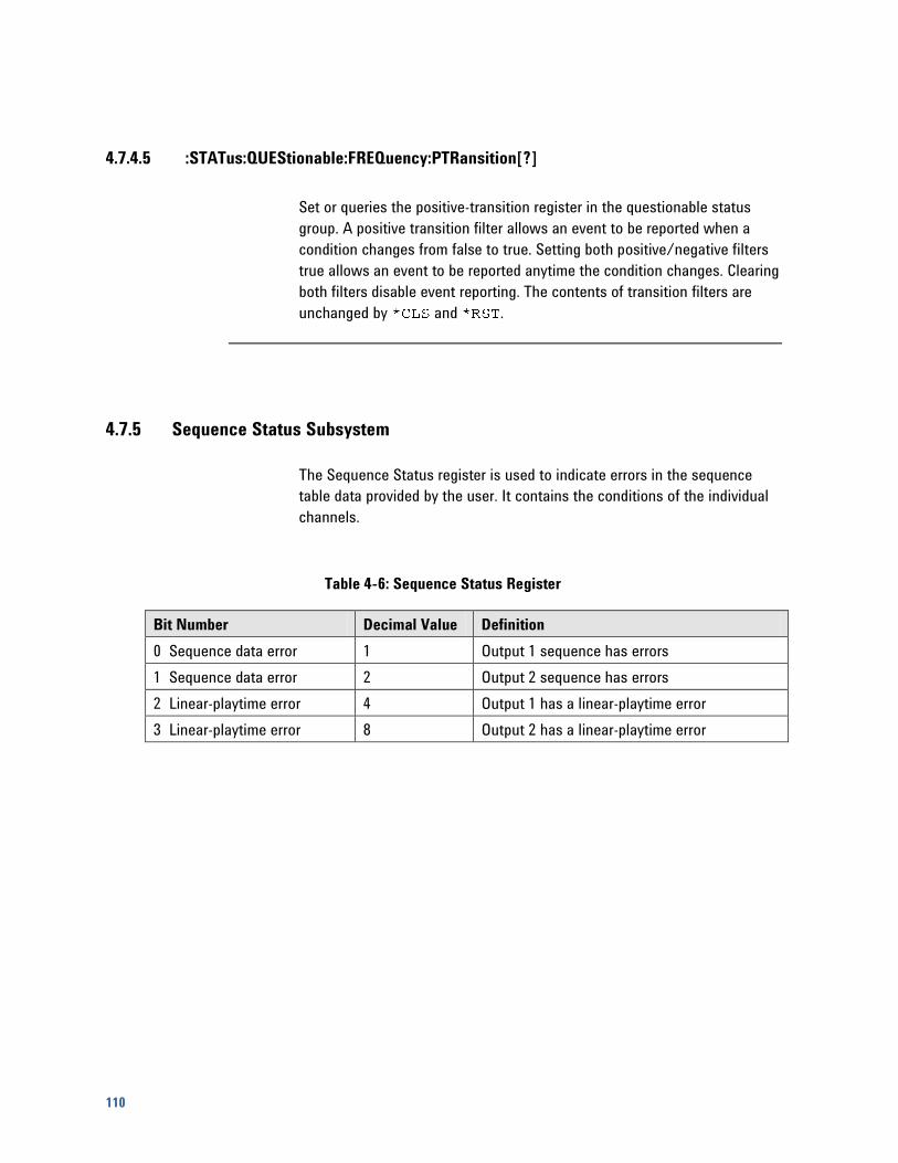
110
4.7.4.5 :STATus:QUEStionable:FREQuency:PTRansition[?]
Set or queries the positive-transition register in the questionable status
group. A positive transition filter allows an event to be reported when a
condition changes from false to true. Setting both positive/negative filters
true allows an event to be reported anytime the condition changes. Clearing
both filters disable event reporting. The contents of transition filters are
unchanged by and .
4.7.5 Sequence Status Subsystem
The Sequence Status register is used to indicate errors in the sequence
table data provided by the user. It contains the conditions of the individual
channels.
Table 4-6: Sequence Status Register
Bit Number Decimal Value Definition
0 Sequence data error 1 Output 1 sequence has errors
1 Sequence data error 2 Output 2 sequence has errors
2 Linear-playtime error 4 Output 1 has a linear-playtime error
3 Linear-playtime error 8 Output 2 has a linear-playtime error
General Programming
M8190A User’s Guide 111
The following commands access the sequence status group.
4.7.5.1 :STATus:QUEStionable:SEQuence[:EVENt]?
Reads the event register in the questionable status group. It’s a read-only
register. Once a bit is set, it remains set until cleared by this command or
command. A query of the register returns a decimal value which
corresponds to the binary-weighted sum of all bits set in the register.
4.7.5.2 :STATus:QUEStionable:SEQuence:CONDition?
Reads the condition register in the questionable status group. It’s a read-
only register and bits are not cleared when you read the register. A query of
the register returns a decimal value which corresponds to the binary-
weighted sum of all bits set in the register.
4.7.5.3 :STATus:QUEStionable:SEQuence:ENABle[?]
Sets or queries the enable register in the questionable status group. The
selected bits are then reported to the Status Byte. A will not clear the
enable register but it does clear all bits in the event register. To enable bits
in the enable register, you must write a decimal value which corresponds to
the binary-weighted sum of the bits you wish to enable in the register.
4.7.5.4 :STATus:QUEStionable:SEQuence:NTRansition[?]
Sets or queries the negative-transition register in the questionable status
group. A negative transition filter allows an event to be reported when a
condition changes from true to false. Setting both positive/negative filters
true allows an event to be reported anytime the condition changes. Clearing
both filters disable event reporting. The contents of transition filters are
unchanged by and .
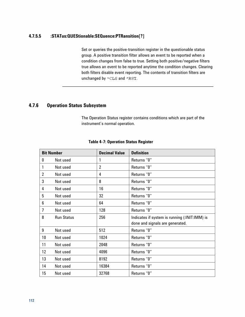
112
4.7.5.5 :STATus:QUEStionable:SEQuence:PTRansition[?]
Set or queries the positive-transition register in the questionable status
group. A positive transition filter allows an event to be reported when a
condition changes from false to true. Setting both positive/negative filters
true allows an event to be reported anytime the condition changes. Clearing
both filters disable event reporting. The contents of transition filters are
unchanged by and .
4.7.6 Operation Status Subsystem
The Operation Status register contains conditions which are part of the
instrument’s normal operation.
Table 4-7: Operation Status Register
Bit Number Decimal Value Definition
0 Not used 1 Returns “0”
1 Not used 2 Returns “0”
2 Not used 4 Returns “0”
3 Not used 8 Returns “0”
4 Not used 16 Returns “0”
5 Not used 32 Returns “0”
6 Not used 64 Returns “0”
7 Not used 128 Returns “0”
8 Run Status 256 Indicates if system is running (:INIT:IMM) is
done and signals are generated.
9 Not used 512 Returns “0”
10 Not used 1024 Returns “0”
11 Not used 2048 Returns “0”
12 Not used 4096 Returns “0”
13 Not used 8192 Returns “0”
14 Not used 16384 Returns “0”
15 Not used 32768 Returns “0”
General Programming
M8190A User’s Guide 113
The following commands access the operation status group.
4.7.6.1 :STATus:OPERation[:EVENt]?
Reads the event register in the operation status group. It’s a read-only
register. Once a bit is set, it remains set until cleared by this command or
command. A query of the register returns a decimal value which
corresponds to the binary-weighted sum of all bits set in the register.
4.7.6.2 :STATus:OPERation:CONDition?
Reads the condition register in the operation status group. It’s a read-only
register and bits are not cleared when you read the register. A query of the
register returns a decimal value which corresponds to the binary-weighted
sum of all bits set in the register.
4.7.6.3 :STATus:OPERation:ENABle[?]
Sets or queries the enable register in the operation status group. The
selected bits are then reported to the Status Byte. A will not clear the
enable register but it does clear all bits in the event register. To enable bits
in the enable register, you must write a decimal value which corresponds to
the binary-weighted sum of the bits you wish to enable in the register.
4.7.6.4 :STATus:OPERation:NTRansition[?]
Sets or queries the negative-transition register in the operation status group.
A negative transition filter allows an event to be reported when a condition
changes from true to false. Setting both positive/negative filters true allows
an event to be reported anytime the condition changes. Clearing both filters
disable event reporting. The contents of transition filters are unchanged by
and .
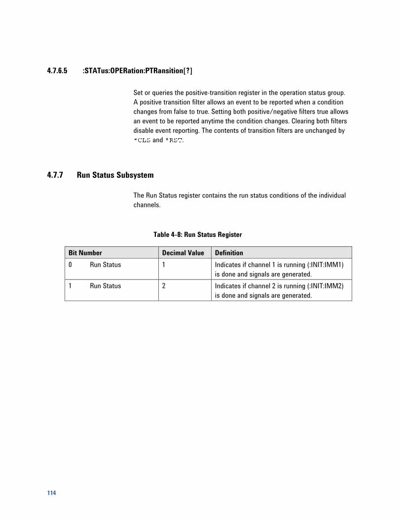
114
4.7.6.5 :STATus:OPERation:PTRansition[?]
Set or queries the positive-transition register in the operation status group.
A positive transition filter allows an event to be reported when a condition
changes from false to true. Setting both positive/negative filters true allows
an event to be reported anytime the condition changes. Clearing both filters
disable event reporting. The contents of transition filters are unchanged by
and .
4.7.7 Run Status Subsystem
The Run Status register contains the run status conditions of the individual
channels.
Table 4-8: Run Status Register
Bit Number Decimal Value Definition
0 Run Status 1 Indicates if channel 1 is running (:INIT:IMM1)
is done and signals are generated.
1 Run Status 2 Indicates if channel 2 is running (:INIT:IMM2)
is done and signals are generated.
General Programming
M8190A User’s Guide 115
The following commands access the frequency operation status group.
4.7.7.1 :STATus:OPERation:RUN[:EVENt]?
Reads the event register in the run operation status group. It’s a read-only
register. Once a bit is set, it remains set until cleared by this command or
command. A query of the register returns a decimal value which
corresponds to the binary-weighted sum of all bits set in the register.
4.7.7.2 :STATus:OPERation:RUN:CONDition?
Reads the condition register in the run operation status group. It’s a read-
only register and bits are not cleared when you read the register. A query of
the register returns a decimal value which corresponds to the binary-
weighted sum of all bits set in the register.
4.7.7.3 :STATus:OPERation:RUN:ENABle[?]
Sets or queries the enable register in the run operation status group. The
selected bits are then reported to the Status Byte. A will not clear the
enable register but it does clear all bits in the event register. To enable bits
in the enable register, you must write a decimal value which corresponds to
the binary-weighted sum of the bits you wish to enable in the register.
4.7.7.4 :STATus:OPERation:RUN:NTRansition[?]
Sets or queries the negative-transition register in the run operation status
group. A negative transition filter allows an event to be reported when a
condition changes from true to false. Setting both positive/negative filters
true allows an event to be reported anytime the condition changes. Clearing
both filters disable event reporting. The contents of transition filters are
unchanged by and .

116
4.7.7.5 :STATus:OPERation:RUN:PTRansition[?]
Set or queries the positive-transition register in the run operation status
group. A positive transition filter allows an event to be reported when a
condition changes from false to true. Setting both positive/negative filters
true allows an event to be reported anytime the condition changes. Clearing
both filters disable event reporting. The contents of transition filters are
unchanged by and .
4.8 :ARM/TRIGger Subsystem
4.8.1 :ABORt[1|2]
Stop signal generation on channel. If channels are coupled, both channels
are stopped.
4.8.2 :ARM[:SEQuence][:STARt][:LAYer]:DELay[1|2][?]
<delay>|MINimum|MAXimum
Set or query the fine delay settings. The unit is in seconds.
Table 4-9: Fine Delay Settings
Sample Frequency Fine Delay Range
fSa ≥ 6.25 GSa/s 0 .. 30e-12
2.5 GSa/s ≤ fSa < 6.25 GSa/s 0 .. 60e-12
fSa < 2.5 GSa/s 0 .. 150e-12
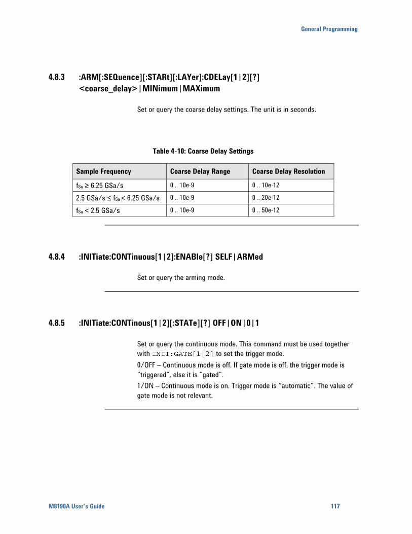
General Programming
M8190A User’s Guide 117
4.8.3 :ARM[:SEQuence][:STARt][:LAYer]:CDELay[1|2][?]
<coarse_delay>|MINimum|MAXimum
Set or query the coarse delay settings. The unit is in seconds.
Table 4-10: Coarse Delay Settings
Sample Frequency Coarse Delay Range Coarse Delay Resolution
fSa ≥ 6.25 GSa/s 0 .. 10e-9 0 .. 10e-12
2.5 GSa/s ≤ fSa < 6.25 GSa/s 0 .. 10e-9 0 .. 20e-12
fSa < 2.5 GSa/s 0 .. 10e-9 0 .. 50e-12
4.8.4 :INITiate:CONTinuous[1|2]:ENABle[?] SELF|ARMed
Set or query the arming mode.
4.8.5 :INITiate:CONTinous[1|2][:STATe][?] OFF|ON|0|1
Set or query the continuous mode. This command must be used together
with to set the trigger mode.
0/OFF – Continuous mode is off. If gate mode is off, the trigger mode is
“triggered”, else it is “gated”.
1/ON – Continuous mode is on. Trigger mode is “automatic”. The value of
gate mode is not relevant.
118
4.8.6 :INITiate:GATE[1|2][:STATe][?] OFF|ON|0|1
Set or query the gate mode. This command must be used together with
to set the trigger mode.
0/OFF – Gate mode is off.
1/ON – Gate mode is on. If continuous mode is on, the trigger mode is
“gated”.
4.8.7 :INITiate:IMMediate[1|2]
Start signal generation on a channel. If channels are coupled, both channels
are started.
4.8.8 :ARM[:SEQuence][:STARt][:LAYer]:TRIGger:LEVel[?]
<level>|MINimum|MAXimum
Set or query the trigger input threshold level.
<level> – Threshold level voltage.
4.8.9 :ARM[:SEQuence][:STARt][:LAYer]:TRIGger:IMPedance[?] LOW|HIGH
Set or query the trigger input impedance.
LOW – low impedance
HIGH – high impedance
General Programming
M8190A User’s Guide 119
4.8.10 :ARM[:SEQuence][:STARt][:LAYer]:TRIGger:SLOPe[?]
POSitive|NEGative|EITHer
Set or query the trigger input slope.
POSitive – rising edge
NEGative – falling edge
EITHer – both
4.8.11 :ARM[:SEQuence][:STARt][:LAYer]:TRIGger:SOURce[?] EXTernal|INTernal
Set or query the source for the trigger function.
EXTernal – external trigger input
INTernal – internal trigger generator
4.8.12 :ARM[:SEQuence][:STARt][:LAYer]:TRIGger:FREQuency[?]
<frequency>|MINimum|MAXimum
Set or query the frequency of the internal trigger generator.
<frequency> – internal trigger frequency
4.8.13 :ARM[:SEQuence][:STARt][:LAYer]:EVENt:LEVel[?]
<level>|MINimum|MAXimum
Set or query the input threshold level.
<level> – Threshold level voltage.
120
4.8.14 :ARM[:SEQuence][:STARt][:LAYer]:EVENt:IMPedance[?] LOW|HIGH
Set or query the event input impedance.
LOW – low impedance
HIGH – high impedance
4.8.15 :ARM[:SEQuence][:STARt][:LAYer]:EVENt:SLOPe[?]
POSitive|NEGative|EITHer
Set or query the event input slope.
POSitive – rising edge
NEGative – falling edge
EITHer – both
4.8.16 :ARM[:SEQuence][:STARt][:LAYer]:DYNPort:WIDTh[?]
LOWerbits|ALLBits
Use this command to set or query the number of valid bits of the dynamic
control input. The input connector has 13 data pins Data_In[0..12], a
Data_Select and a Load pin. Internally, 19 bits of data are used, which are
multiplexed using Data_Select. Data_In[0..12] and Data_Select will be
stored on rising edge of Load signal.
LOWerbits – 13 Bits are used to select a segment dynamically. Data_Select
= Low: Data[0..12] = Data_In[0..12]. Data[13..18] = 0.
ALLBits – 19 Bits are used to select a segment dynamically. Data_Select =
Low: Data[0..12] = Data_In[0..12]. Data_Select = High: Data[13..18] =
Data_In[0..5].
4.8.17 :TRIGger[:SEQuence][:STARt]:SOURce:ENABle[?] TRIGger|EVENt
Set or query the source for the enable event.
TRIGger - trigger input
EVENt - event input
General Programming
M8190A User’s Guide 121
4.9 TRIGger - Trigger Input
4.9.1 :TRIGger[:SEQuence][:STARt]:SOURce:ADVance[?] TRIGger|EVENt
Set or query the source for the advancement event.
TRIGger - trigger input
EVENt - event input
4.9.2 :TRIGger[:SEQuence][:STARt]:ENABle[1|2][:IMMediate]
Send the enable event to a channel.
4.9.3 :TRIGger[:SEQuence][:STARt]:BEGin[1|2][:IMMediate]
In triggered mode send the start/begin event to a channel.
4.9.4 :TRIGger[:SEQuence][:STARt]:BEGin[1|2]:GATE[:STATe] OFF|ON|0|1
In gated mode send a “gate open” (ON|1) or “gate close” (OFF|0) to a
channel.
4.9.5 :TRIGger[:SEQuence][:STARt]:ADVance[1|2][:IMMediate]
Send the advancement event to a channel.
122
4.10 :FORMat Subsystem
4.10.1 :FORMat:BORDer NORMal|SWAPped
Byte ORDer. Controls whether binary data is transferred in normal (“big
endian”) or swapped (“little endian”) byte order. Affects
, and
.
4.11 :INSTrument Subsystem
4.11.1 :INSTrument:COUPle:STATe[1|2][?] ON|OFF
Note: not available with B02 option.
Switch coupling on/off. If coupling is switched on, the values of the channel
where coupling is switched on are taken. Coupled values are:
FREQ:RAST:SOUR[1|2]
TRAC[1|2]:DWID
OUTP:SCLK:SOUR
4.11.2 :INSTrument:SLOT[:NUMBer]?
Query the instrument’s slot number in its AXIe frame.
General Programming
M8190A User’s Guide 123
4.12 :MMEMory Subsystem
Note: MMEM commands requiring <directory_name> assume the current
directory if a relative path or no path is provided. If an absolute path is
provided, then it is ignored.
4.12.1 :MMEMory:CATalog? [<directory_name>]
Query disk usage information (drive capacity, free space available) and
obtain a list of files and directories in a specified directory in the following
format:
<numeric_value>,<numeric_value>,{<file_entry>}
This command returns two numeric parameters and as many strings as
there are files and directories. The first parameter indicates the total amount
of storage currently used in bytes. The second parameter indicates the total
amount of storage available, also in bytes. The <file_entry> is a string. Each
<file_entry> indicates the name, type, and size of one file in the directory
list:
<file_name>,<file_type>,<file_size>
As the Windows file system has an extension that indicates file type,
<file_type> is always empty. <file_size> provides the size of the file in
bytes. In case of directories, <file_entry> is surrounded by square brackets
and both <file_type> and <file_size> are empty.
4.12.2 :MMEMory:CDIRectory [<directory_name>]
Changes the default directory for a mass memory file system. The
<directory_name> parameter is a string. If no parameter is specified, the
directory is set to the value. At , this value is set to the default
user data storage area, that is defined as
System.Environment.SpecialFolder.Personal
e.g. C:\Users\Name\Documents
— Query returns full path of the default
directory.
124
4.12.3 :MMEMory:COPY <string>,<string>[,<string>,<string>]
Copies an existing file to a new file or an existing directory to a new
directory. Two forms of parameters are allowed. The first form has two
parameters. In this form, the first parameter specifies the source, and the
second parameter specifies the destination.
The second form has four parameters. In this form, the first and third
parameters specify the file names. The second and fourth parameters
specify the directories. The first pair of parameters specifies the source. The
second pair specifies the destination. An error is generated if the source
doesn't exist or the destination file already exists.
4.12.4 :MMEMory:DELete <file_name>[,<directory_name>]
Removes a file from the specified directory. The <file_name> parameter
specifies the file to be removed.
4.12.5 :MMEMory:DATA <file_name>, <data>
The command form is . It
loads <data> into the file <file_name>. <data> is in 488.2 block format.
<file_name> is string data.
4.12.6 :MMEMory:DATA? <file_name>
The query form is > with the response
being the associated <data> in block format.
4.12.7 :MMEMory:MDIRectory <directory_name>
Creates a new directory. The <directory_name> parameter specifies the
name to be created.

General Programming
M8190A User’s Guide 125
4.12.8 :MMEMory:MOVE <string>,<string>[,<string>,<string>]
Moves an existing file to a new file or an existing directory to a new
directory. Two forms of parameters are allowed. The first form has two
parameters. In this form, the first parameter specifies the source, and the
second parameter specifies the destination.
The second form has four parameters. In this form, the first and third
parameters specify the file names. The second and fourth parameters
specify the directories. The first pair of parameters specifies the source. The
second pair specifies the destination. An error is generated if the source
doesn't exist or the destination file already exists.
4.12.9 :MMEMory:RDIRectory <directory_name>
Removes a directory. The <directory_name> parameter specifies the
directory name to be removed. All files and directories under the specified
directory are also removed.
4.12.10 :MMEMory:LOAD:CSTate <file_name>
Current STate of instrument is loaded from a file.
4.12.11 :MMEMory:STORe:CSTate <file_name>
Current STate of instrument is stored to a file.
126
4.13 :OUTPut Subsystem
4.13.1 :OUTPut[1|2][:NORMal][:STATe][?] 0|1|ON|OFF
Switch (normal) output on or off.
4.13.2 :OUTPut[1|2]:COMPlement[:STATe][?] 0|1|ON|OFF
Switch complement output on or off.
Notes:
Only affects route “DC”.
4.13.3 :OUTPut:SCLK:SOURce[?] INTernal|EXTernal
Note: not supported for Rev. 1 Modules (-B02)
Select which clock source is routed to the SCLK output:
INTernal: the internally generated clock
EXTernal: the clock that is received at SCLK input
4.13.4 :OUTPut[1|2]:ROUTe[:SELect][?] DAC|DC|AC
Select the output path:
DAC: Direct DAC output
DC: Amplified differential output
AC: Single ended AC coupled output with up to 10 dBm output level
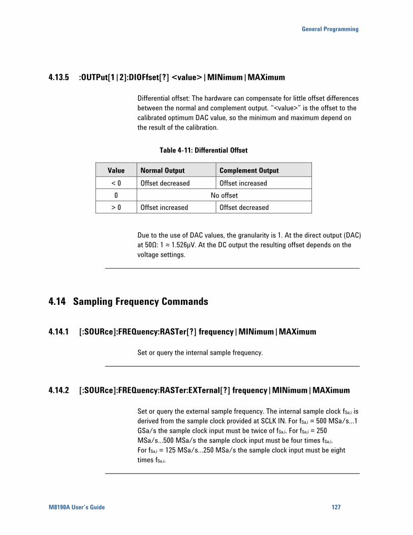
General Programming
M8190A User’s Guide 127
4.13.5 :OUTPut[1|2]:DIOFfset[?] <value>|MINimum|MAXimum
Differential offset: The hardware can compensate for little offset differences
between the normal and complement output. “<value>” is the offset to the
calibrated optimum DAC value, so the minimum and maximum depend on
the result of the calibration. offset adjustment
Table 4-11: Differential Offset
Value Normal Output Complement Output
< 0 Offset decreased Offset increased
0 No offset
> 0 Offset increased Offset decreased
Due to the use of DAC values, the granularity is 1. At the direct output (DAC)
at 50Ω: 1 ≈ 1.526μV. At the DC output the resulting offset depends on the
voltage settings.
4.14 Sampling Frequency Commands
4.14.1 [:SOURce]:FREQuency:RASTer[?] frequency|MINimum|MAXimum
Set or query the internal sample frequency.
4.14.2 [:SOURce]:FREQuency:RASTer:EXTernal[?] frequency|MINimum|MAXimum
Set or query the external sample frequency. The internal sample clock fSa,i is
derived from the sample clock provided at SCLK IN. For fSa,i = 500 MSa/s…1
GSa/s the sample clock input must be twice of fSa,i. For fSa,i = 250
MSa/s…500 MSa/s the sample clock input must be four times fSa,i.
For fSa,i = 125 MSa/s…250 MSa/s the sample clock input must be eight
times fSa,i.
128
4.14.3 [:SOURce]:FREQuency:RASTer:SOURce[1|2][?] INTernal|EXTernal
Set or query the selected clock source for a channel. When switching to
EXTernal a stable sample clock that matches the frequency set with
must be supplied at SCLK IN.
4.15 Reference Frequency Commands
4.15.1 [:SOURce]:ROSCillator:SOURce[?] EXTernal|AXI
Set or query the reference clock source.
EXTernal: reference is taken from REF CLK IN.
AXI: reference is taken from AXI backplane.
Command not supported with Revision 1 hardware.
4.15.2 [:SOURce]:ROSCillator:FREQuency[?] <frequency>|MINimum|MAXimum
Set or query the expected reference clock frequency, if the external
reference clock source is selected.
4.16 :DAC|DC|AC Subsystem
Set or query voltages or format for the different output paths (DAC, DC, AC
selected with the command).
4.16.1 [:SOURce]:DAC|DC|AC[1|2]:FORMat[?] RZ|DNRZ|NRZ|DOUBlet
Set or query the DAC format mode.
DAC Format Modes For further details, refer to the section NRZ / DNRZ / Doublet.
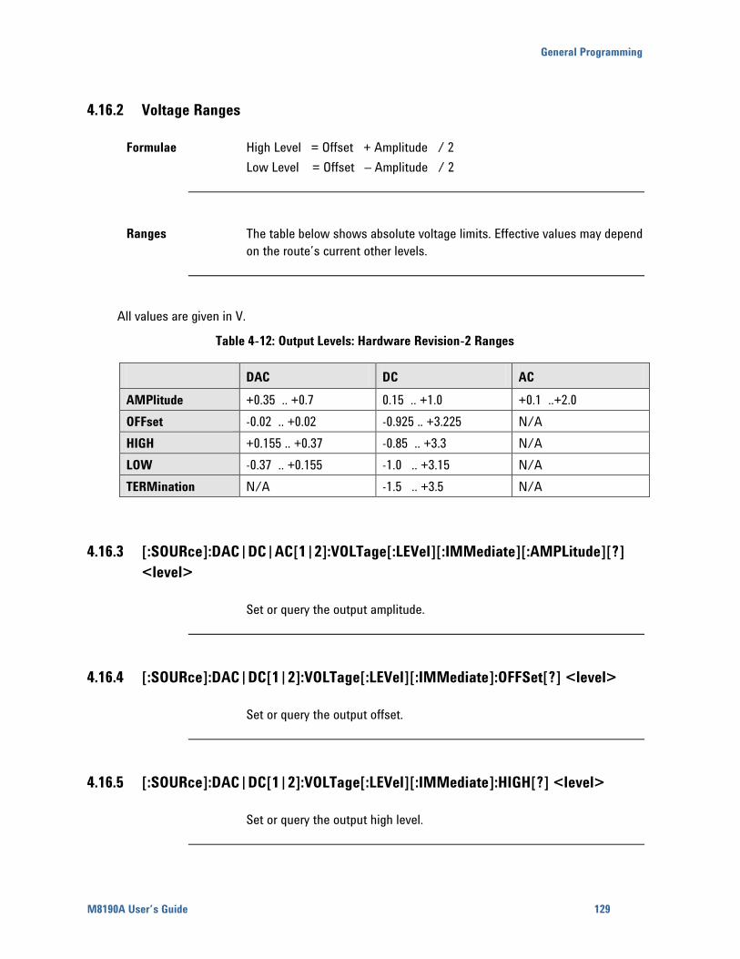
General Programming
M8190A User’s Guide 129
4.16.2 Voltage Ranges
Formulae High Level = Offset + Amplitude / 2
Low Level = Offset – Amplitude / 2
Ranges The table below shows absolute voltage limits. Effective values may depend
on the route’s current other levels.
All values are given in V.
Table 4-12: Output Levels: Hardware Revision-2 Ranges
DAC DC AC
AMPlitude +0.35 .. +0.7 0.15 .. +1.0 +0.1 ..+2.0
OFFset -0.02 .. +0.02 -0.925 .. +3.225 N/A
HIGH +0.155 .. +0.37 -0.85 .. +3.3 N/A
LOW -0.37 .. +0.155 -1.0 .. +3.15 N/A
TERMination N/A -1.5 .. +3.5 N/A
4.16.3 [:SOURce]:DAC|DC|AC[1|2]:VOLTage[:LEVel][:IMMediate][:AMPLitude][?]
<level>
Set or query the output amplitude.
4.16.4 [:SOURce]:DAC|DC[1|2]:VOLTage[:LEVel][:IMMediate]:OFFSet[?] <level>
Set or query the output offset.
4.16.5 [:SOURce]:DAC|DC[1|2]:VOLTage[:LEVel][:IMMediate]:HIGH[?] <level>
Set or query the output high level.
130
4.16.6 [:SOURce]:DAC|DC[1|2]:VOLTage[:LEVel][:IMMediate]:LOW[?] <level>
Set or query the output low level.
4.16.7 [:SOURce]:DC[1|2]:VOLTage[:LEVel][:IMMediate]:TERMination[?] <level>
Set or query the termination voltage level.
4.17 :VOLTage Subsystem
Set the voltages for the currently selected output path (DAC, DC, or AC;
selected with the command).
4.17.1 [:SOURce]:VOLTage[1|2][:LEVel][:IMMediate][:AMPLitude][?] <level>
Set or query the output amplitude.
4.17.2 [:SOURce]:VOLTage[1|2][:LEVel][:IMMediate]:OFFSet[?] <level>
Set or query the output offset.
4.17.3 [:SOURce]:VOLTage[1|2][:LEVel][:IMMediate]:HIGH[?] <level>
Set or query the output high level.
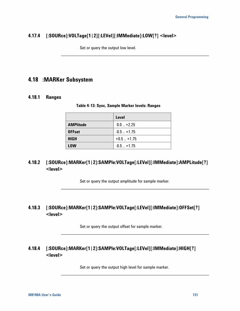
General Programming
M8190A User’s Guide 131
4.17.4 [:SOURce]:VOLTage[1|2][:LEVel][:IMMediate]:LOW[?] <level>
Set or query the output low level.
4.18 :MARKer Subsystem
4.18.1 Ranges
Table 4-13: Sync, Sample Marker levels: Ranges
Level
AMPlitude 0.0 .. +2.25
OFFset -0.5 .. +1.75
HIGH +0.5 .. +1.75
LOW -0.5 .. +1.75
4.18.2 [:SOURce]:MARKer[1|2]:SAMPle:VOLTage[:LEVel][:IMMediate]:AMPLitude[?]
<level>
Set or query the output amplitude for sample marker.
4.18.3 [:SOURce]:MARKer[1|2]:SAMPle:VOLTage[:LEVel][:IMMediate]:OFFSet[?]
<level>
Set or query the output offset for sample marker.
4.18.4 [:SOURce]:MARKer[1|2]:SAMPle:VOLTage[:LEVel][:IMMediate]:HIGH[?]
<level>
Set or query the output high level for sample marker.
132
4.18.5 [:SOURce]:MARKer[1|2]:SAMPle:VOLTage[:LEVel][:IMMediate]:LOW[?]
<level>
Set or query the output low level for sample marker.
4.18.6 [:SOURce]:MARKer[1|2]:SYNC:VOLTage[:LEVel][:IMMediate]:AMPLitude[?]
<level>
Set or query the output amplitude for sync marker.
4.18.7 [:SOURce]:MARKer[1|2]:SYNC:VOLTage[:LEVel][:IMMediate]:OFFSet[?]
<level>
Set or query the output offset for sync marker.
4.18.8 [:SOURce]:MARKer[1|2]:SYNC:VOLTage[:LEVel][:IMMediate]:HIGH[?]
<level>
Set or query the output high level for sync marker.
4.18.9 [:SOURce]:MARKer[1|2]:SYNC:VOLTage[:LEVel][:IMMediate]:LOW[?] <level>
Set or query the output low level for sync marker.
General Programming
M8190A User’s Guide 133
4.19 :FUNCtion[1|2]:MODE ARBitrary|STSequence|STSCenario
Use this command to set or query the type of waveform that will be
generated.
ARBitrary – arbitrary waveform segment
STSequence – sequence
STSCenario – scenario
4.20 :SEQuence Subsystem
Sequences are made of a number of arbitrary waveforms, which can be
linked and looped in user-programmable order. Sequences are generated
from waveforms stored in the waveform memory as memory segments.
Steps to generate a sequence:
Generate the waveform segments using the Arbitrary Waveform
Commands (TRACe Subsystem).
Define a sequence (:SEQ[1|2]:DEF:NEW).
Fill the sequence with segments (:SEQ[1|2]:DATA).
Select sequence mode (:SOUR:FUNC[1|2]:MODE STSequence).
Select a sequence (:STAB[1|2]:SEQ:SEL).
Start signal generation with :INIT:IMM.
This subsystem does not support the following functionality offered by the
STABle subsystem.
Scenarios
Idle delay commands
134
4.20.1 [:SOURce]:SEQuence[1|2]:DEFine:NEW? <length>
<length> number of sequence table entries.
This command defines a new sequence. The <length> parameter specifies
the number of sequence table entries in the sequence.
The new <sequence-id> in the range 0…512K–2 is returned. This value is
the index of the first sequence table entry of this sequence.
4.20.2 [:SOURce]:SEQuence[1|2]:DATA[?]
<sequence_id>,<step>[,<length>|,<value>,<value>…|,<data block>]
<sequence_id> 0…512K-2
<step> sequence table entry in the sequence. Valid range is 0 to <length>-1
defined with seq:def:new
<length> number of sequence steps to be read
The command form writes one or multiple sequence steps beginning at
<step>. Each step consists of 6 32-bit words per entry with the following
meanings.
<segment_id>id of the segment.
<loop_count> number of segment loop iterations 1…4G-1
<advance_mode> 0: AUTO, 1: CONDitional, 2: REPeat, 3: SINGle. Specifies
how the generator advances from one sequence table entry to the next one.
<marker_enable> 0: Marker disabled, 1: Marker enabled
<start_addr> Address of the first sample within the segment to be inserted
into the sequence.
<end_addr> Address of the last sample in the segment to be inserted into
the sequence. You can use 0xffffffff to specify the last sample of the
segment.
Individual entries, multiple entries or even the complete sequence at once
can be written. The data can be given in IEEE binary block format or in
comma separated list of 32-bit values.
The query form returns for a given sequence-id and step the segment data
items (segment-id, loop-count, advance-mode, marker-enable, start-addr,
end-addr).
If the sequence does not exist or the step is greater than the sequence
length – 1, an error is generated.
General Programming
M8190A User’s Guide 135
4.20.3 [:SOURce]:SEQuence[1|2]:DELete <sequence_id>
< sequence_id > 0…512K-2
Delete a sequence.
4.20.4 [:SOURce]:SEQuence[1|2]:DELete:ALL
Delete all sequences.
4.20.5 [:SOURce]:SEQuence[1|2]:CATalog?
The query returns a comma-separated list of sequence-ids that are defined
and the length in segments of each sequence. So first number is a sequence
id, next length …
If no sequence is defined, “0, 0” is returned.
4.20.6 [:SOURce]:SEQuence[1|2]:FREE?
The query returns the number of free sequence entries in the following form:
<sequence entries available>, < sequence entries in use>, < contiguous
sequence entries available>.
4.20.7 [:SOURce]:SEQuence[1|2]:ADVance[?] <sequence_id>,AUTO|CONDitional|
REPeat|SINGle
< sequence_id > 0…512K-2
Set or query the advancement mode between iterations of a sequence.
136
4.20.8 [:SOURce]:SEQuence[1|2]:COUNt <sequence_id>,<count>
< sequence_id > 0…512K-2
<count> 1...4G-1 number of times the sequence is executed.
Set or query the number of iterations of a sequence.
4.20.9 [:SOURce]:SEQuence[1|2]:NAME[?] <sequence_id>,<name>
Associate a <name> to <sequence_id>.
Example:
seq2:name 5,”jim”
4.20.10 [:SOURce]:SEQuence[1|2]:COMMent[?] <sequence_id>,<comment>
Associate a <comment> to <sequence_id>.
Example:
seq2:comm 5,”any information that should be associated with this segment”
4.21 :STABle Subsystem
Use this subsystem to directly manipulate the sequencer table. This is
necessary when full control of the sequence capabilities is desired. Unlike
the SEQuence subsystem the STABle subsystem also supports scenarios
and idle delay commands.
Follow these steps for all function modes:
First create waveform data segments in the module memory like described
in the “Arbitrary Waveform Generation” paragraph of the “TRACe
subsystem”.
Create sequence table entries that refer to the waveform segments using
the command.
The next steps depend on the selected mode:
General Programming
M8190A User’s Guide 137
4.21.1 Generating arbitrary waveforms in dynamic mode
Select the sequence table entry that describes the segment that will be
executed first, before any dynamic segment selection, using the
command.
Select dynamic mode using the command .
Before starting signal generation with select the
arbitrary waveform mode using the command.
4.21.2 Generating sequences in non-dynamic mode
Select the sequence table entry that describes the first segment in your
sequence using the command.
Select non-dynamic mode using the command .
Before starting signal generation with select the
sequence mode using the command.
4.21.3 Generating sequences in dynamic mode
Select the sequence table entry that describes the first segment in your
sequence that will be executed first, before any dynamic sequence
selection, using the command.
Select dynamic mode using the command .
Before starting signal generation with select the
sequence mode using the command.
138
4.21.4 Generating scenarios
Set the scenario advancement mode using the
command.
Set the scenario loop count using the
command.
Select the sequence table entry that describes the first segment in your
scenario using the command.
Select non-dynamic mode using the command .
Before starting signal generation with select the
scenario mode using the command.
4.21.5 [:SOURce]:STABle[1|2]:RESet
Reset all sequence table entries to default values.
4.21.6 [:SOURce]:STABle[1|2]:DATA[?]
<sequence_table_index>,(<block>|<value>,<value>…)
The command form writes directly into the sequencer memory. The query
form reads the data from the sequencer memory, if all segments are read-
write. The query returns an error, if at least one write-only segment in the
waveform memory exists.
The sequencer memory has 524287 (512k – 1) entries. With this command
entries can be directly manipulated using 6 32-bit words per entry. Individual
entries, multiple entries or even the complete sequencer memory at once
can be manipulated. The data can be given in IEEE binary block format or in
comma separated list of 32-bit values.
<sequence_table_index> – 0..512k-2
<block>– up to 512k – 1 sequence vectors, each consisting of 6 32-bit
values
<value>– a 32-bit value as part of a sequence vector
The comma-separated values or the 32-bit values in the IEEE binary block
have the following meaning.
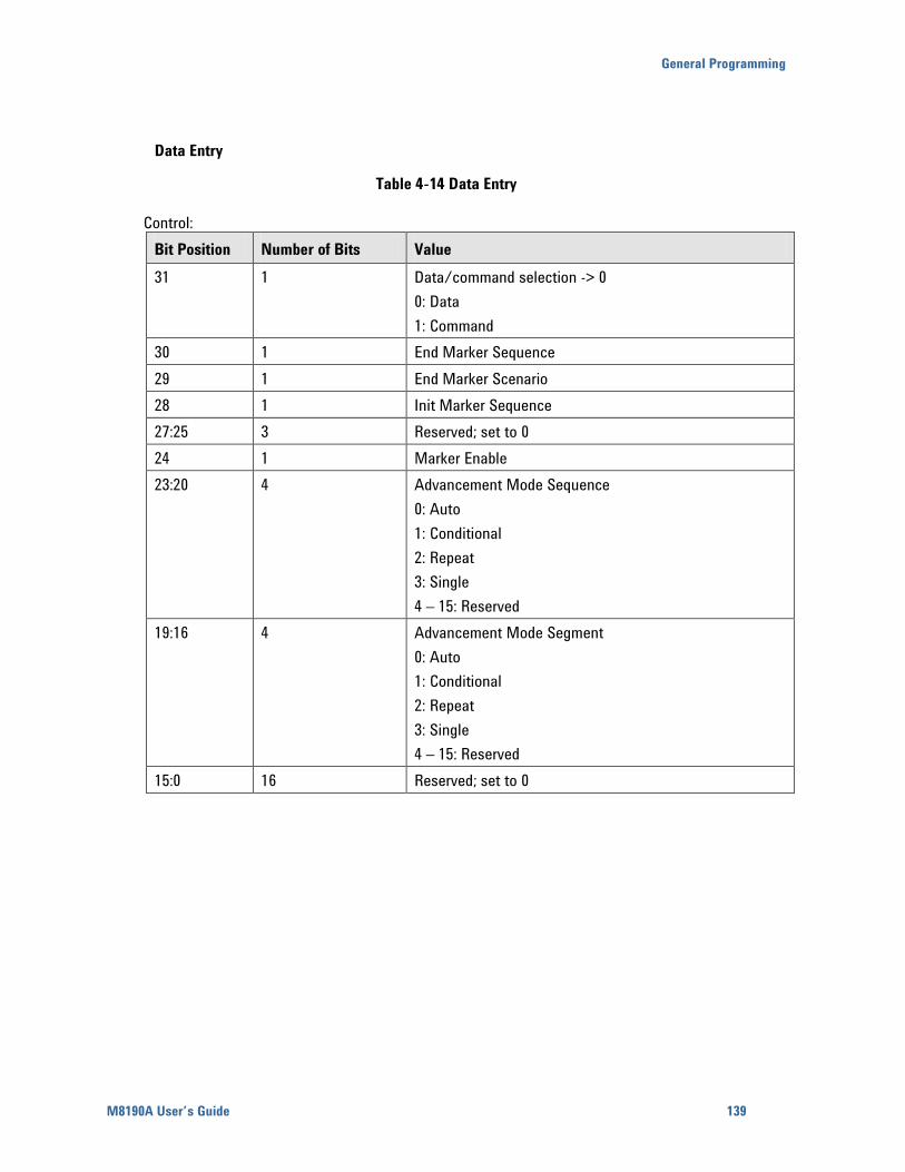
General Programming
M8190A User’s Guide 139
Data Entry
Table 4-14 Data Entry
Control:
Bit Position Number of Bits Value
31 1 Data/command selection -> 0
0: Data
1: Command
30 1 End Marker Sequence
29 1 End Marker Scenario
28 1 Init Marker Sequence
27:25 3 Reserved; set to 0
24 1 Marker Enable
23:20 4 Advancement Mode Sequence
0: Auto
1: Conditional
2: Repeat
3: Single
4 – 15: Reserved
19:16 4 Advancement Mode Segment
0: Auto
1: Conditional
2: Repeat
3: Single
4 – 15: Reserved
15:0 16 Reserved; set to 0
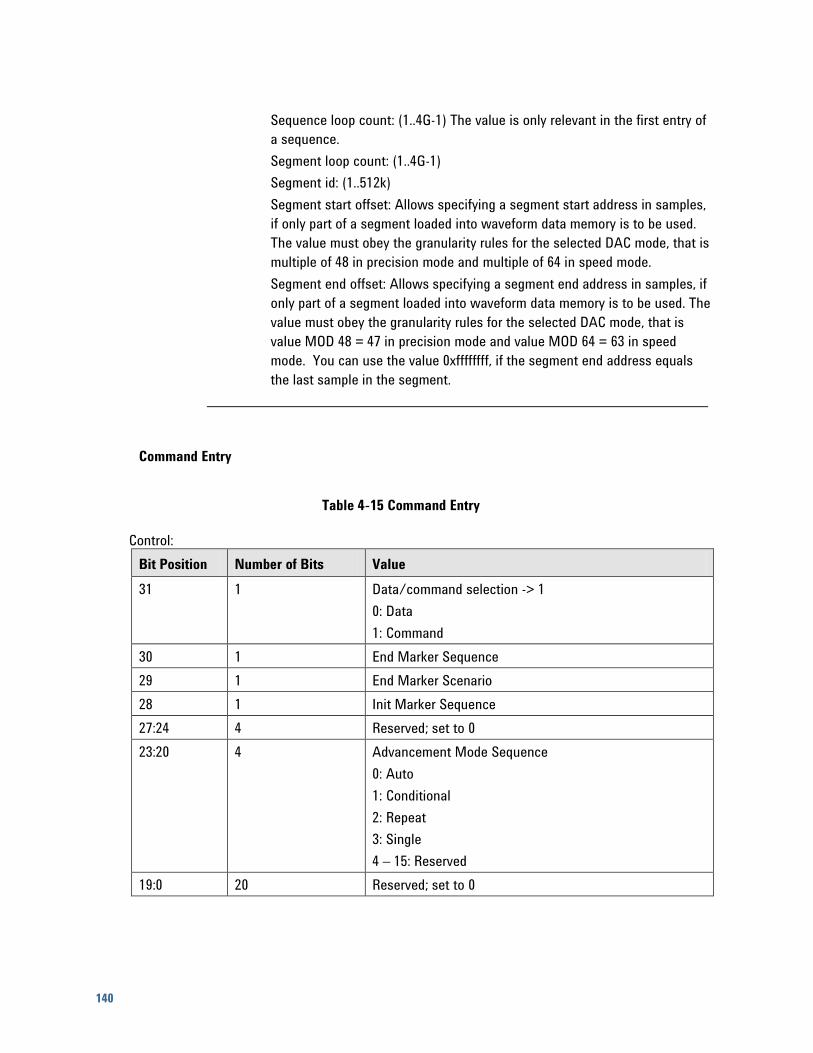
140
Sequence loop count: (1..4G-1) The value is only relevant in the first entry of
a sequence.
Segment loop count: (1..4G-1)
Segment id: (1..512k)
Segment start offset: Allows specifying a segment start address in samples,
if only part of a segment loaded into waveform data memory is to be used.
The value must obey the granularity rules for the selected DAC mode, that is
multiple of 48 in precision mode and multiple of 64 in speed mode.
Segment end offset: Allows specifying a segment end address in samples, if
only part of a segment loaded into waveform data memory is to be used. The
value must obey the granularity rules for the selected DAC mode, that is
value MOD 48 = 47 in precision mode and value MOD 64 = 63 in speed
mode. You can use the value 0xffffffff, if the segment end address equals
the last sample in the segment.
Command Entry
Table 4-15 Command Entry
Control:
Bit Position Number of Bits Value
31 1 Data/command selection -> 1
0: Data
1: Command
30 1 End Marker Sequence
29 1 End Marker Scenario
28 1 Init Marker Sequence
27:24 4 Reserved; set to 0
23:20 4 Advancement Mode Sequence
0: Auto
1: Conditional
2: Repeat
3: Single
4 – 15: Reserved
19:0 20 Reserved; set to 0
General Programming
M8190A User’s Guide 141
Sequence loop count: (1..4G-1)
Command code: Currently only Idle Delay (0) with the following parameters
is supported.
Idle Sample: Sample to be played during pause. Bits 13:0 are used in
precision mode, bits 11:0 in speed mode.
Delay in sample clocks: In precision mode the range is between 10 * 48 and
225 * 48 + 47, in speed mode between 10 * 64 and 225 * 64 + 63.
Unused last 32-bit word: set to 0.
4.21.7 [:SOURce]:STABle[1|2]:SEQuence:SELect[?] <sequence_table_index>
Select where in the sequence table the sequence starts in STSequence
mode. In dynamic sequence selection mode select the sequence that is
played before the first sequence is dynamically selected.
4.21.8 [:SOURce]:STABle[1|2]:DYNamic:[STATe][?] 0|1|ON|OFF
Use this command to enable or disable dynamic mode.
If dynamic mode is switched off, segments or sequences can only be
switched in program mode, that is signal generation must be stopped. In
arbitrary mode use to switch to a new segment.
In sequence mode
to switch to a new
sequence.
If dynamic mode is switched on, segments or sequences can be switched
dynamically when signal generation is active. The next segment or sequence
is either selected by the command
or by a signal fed
into the dynamic port on the module front panel. The external input values
select sequence table entries with corresponding indices.
The number of valid bits of the dynamic port is specified by the
command.
142
4.21.9 [:SOURce]:STABle[1|2]:DYNamic:SELect[?] <sequence_table_index>
When the dynamic mode for segments or sequences is active, set or query
the selected sequence table entry.
4.21.10 [:SOURce]:STABle[1|2]:SCENario:SELect[?] <sequence_table_index>
Select where in the sequence table the scenario starts in STSCenario mode.
4.21.11 [:SOURce]:STABle[1|2]:SCENario:ADVance[?]
AUTO|CONDitional|REPeat|SINGle
Set or query the advancement mode for scenarios.
4.21.12 [:SOURce]:STABle[1|2]:SCENario:COUNt[?] <count>
Set or query the loop count for scenarios.
<count> – 1..4G-1: number of times the scenario is repeated.
4.22 :TRACe Subsystem
Use this subsystem to control the arbitrary waveforms and their respective
parameters. It allows you to create segments and download waveforms.
Using these commands, you can also define segment size and delete some
or all unwanted waveforms from the module memory.
General Programming
M8190A User’s Guide 143
4.22.1 Waveform Memory Management
Arbitrary waveforms are generated from DAC values, which are stored in a
dedicated waveform memory. Each DAC value has a resolution of 12 bits in
speed mode and 14 bits in precision mode.
The module has the following waveform memory capacity:
128 MSa – standard memory configuration in precision and speed mode
1.5 GSa – precision mode with option 02 G
2 GSa – speed mode with option 02 G
The data memory is internally organized in memory vectors consisting of 48
samples in precision mode and 64 samples in speed mode. The segment
size in samples must be a multiple of 48 in precision mode and of 64 in
speed mode. The minimum segment size is 5 memory vectors. The
maximum segment size is only limited by the size of the available memory.
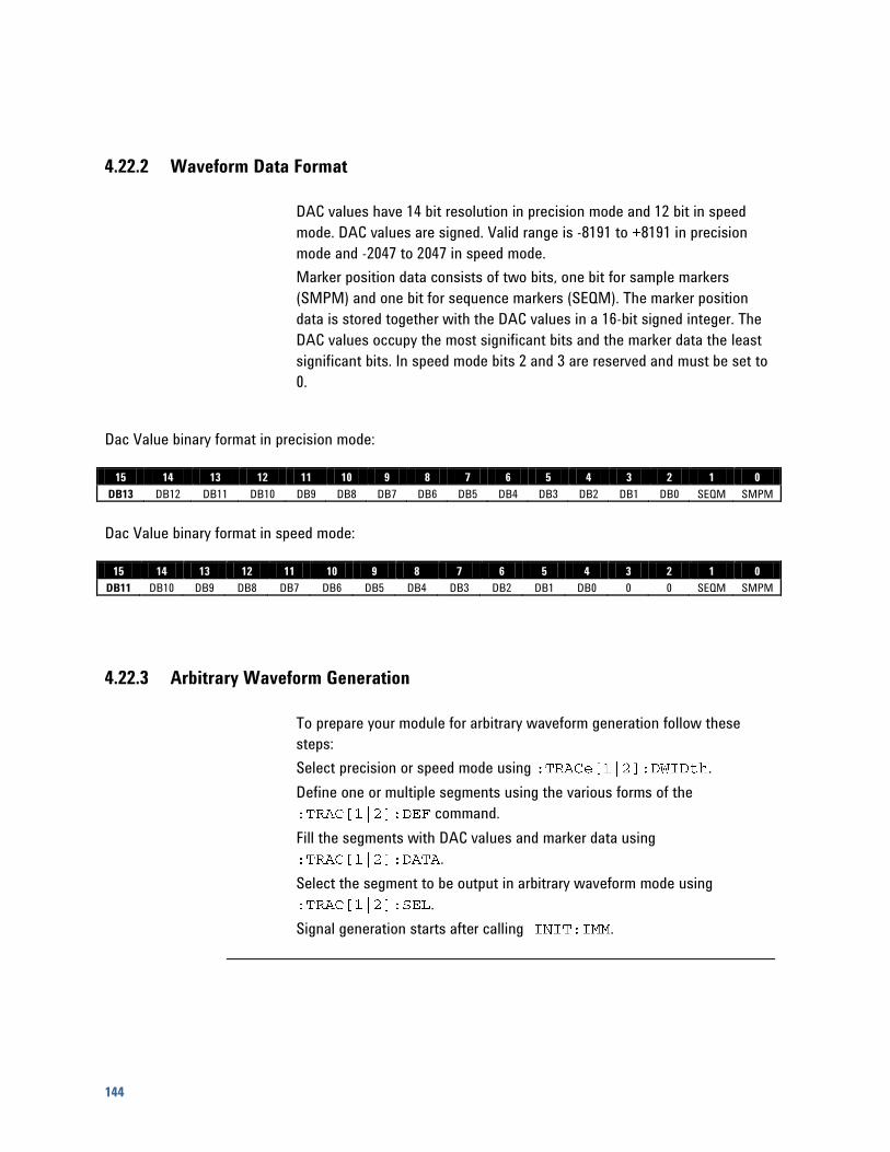
144
4.22.2 Waveform Data Format
DAC values have 14 bit resolution in precision mode and 12 bit in speed
mode. DAC values are signed. Valid range is -8191 to +8191 in precision
mode and -2047 to 2047 in speed mode.
Marker position data consists of two bits, one bit for sample markers
(SMPM) and one bit for sequence markers (SEQM). The marker position
data is stored together with the DAC values in a 16-bit signed integer. The
DAC values occupy the most significant bits and the marker data the least
significant bits. In speed mode bits 2 and 3 are reserved and must be set to
0.
Dac Value binary format in precision mode:
15 14 13 12 11 10 9 8 7 6 5 4 3 2 1 0
DB13 DB12 DB11 DB10 DB9 DB8 DB7 DB6 DB5 DB4 DB3 DB2 DB1 DB0 SEQM SMPM
Dac Value binary format in speed mode:
15 14 13 12 11 10 9 8 7 6 5 4 3 2 1 0
DB11 DB10 DB9 DB8 DB7 DB6 DB5 DB4 DB3 DB2 DB1 DB0 0 0 SEQM SMPM
4.22.3 Arbitrary Waveform Generation
To prepare your module for arbitrary waveform generation follow these
steps:
Select precision or speed mode using .
Define one or multiple segments using the various forms of the
command.
Fill the segments with DAC values and marker data using
.
Select the segment to be output in arbitrary waveform mode using
.
Signal generation starts after calling .
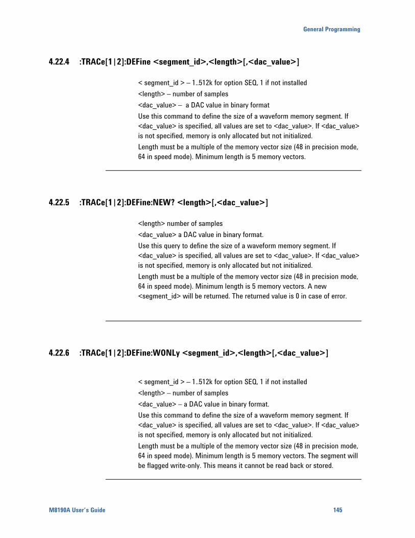
General Programming
M8190A User’s Guide 145
4.22.4 :TRACe[1|2]:DEFine <segment_id>,<length>[,<dac_value>]
< segment_id > – 1..512k for option SEQ, 1 if not installed
<length> – number of samples
<dac_value> – a DAC value in binary format
Use this command to define the size of a waveform memory segment. If
<dac_value> is specified, all values are set to <dac_value>. If <dac_value>
is not specified, memory is only allocated but not initialized.
Length must be a multiple of the memory vector size (48 in precision mode,
64 in speed mode). Minimum length is 5 memory vectors.
4.22.5 :TRACe[1|2]:DEFine:NEW? <length>[,<dac_value>]
<length> number of samples
<dac_value> a DAC value in binary format.
Use this query to define the size of a waveform memory segment. If
<dac_value> is specified, all values are set to <dac_value>. If <dac_value>
is not specified, memory is only allocated but not initialized.
Length must be a multiple of the memory vector size (48 in precision mode,
64 in speed mode). Minimum length is 5 memory vectors. A new
<segment_id> will be returned. The returned value is 0 in case of error.
4.22.6 :TRACe[1|2]:DEFine:WONLy <segment_id>,<length>[,<dac_value>]
< segment_id > – 1..512k for option SEQ, 1 if not installed
<length> – number of samples
<dac_value> – a DAC value in binary format.
Use this command to define the size of a waveform memory segment. If
<dac_value> is specified, all values are set to <dac_value>. If <dac_value>
is not specified, memory is only allocated but not initialized.
Length must be a multiple of the memory vector size (48 in precision mode,
64 in speed mode). Minimum length is 5 memory vectors. The segment will
be flagged write-only. This means it cannot be read back or stored.
146
4.22.7 :TRACe[1|2]:DEFine:WONLy:NEW? <segment_id>,<length>[,<dac_value>]
<length> number of samples
<dac_value> a dac value in binary format.
Use this query to define the size of a waveform memory segment. If
<dac_value> is specified, all values are set to <dacValue>. If <dac_value>
is not specified, memory is only allocated but not initialized.
Length must be a multiple of the memory vector size (48 in precision mode,
64 in speed mode). Minimum length is 5 memory vectors. The segment will
be flagged write-only. This means it cannot be read back or stored. A new
<segment_id> will be returned. The returned value is 0 in case of error.
4.22.8 :TRACe[1|2]:DWIDth[?] WSPeed|WPRecision
WSPeed – speed mode, 12 bit DAC resolution
WPRecision – precision mode, 14 bit DAC resolution
Use this command or query to set or get the DAC width to either support
speed mode or precision mode. If the DAC resolution is changed, all
waveform segments for this channel are invalidated.
General Programming
M8190A User’s Guide 147
4.22.9 :TRACe[1|2][:DATA][?]
<segment_id>,<offset>,(<block>|<numeric_values>)
<segment_id> 1..512k for option SEQ, 1 if not installed
<offset> offset in samples to allow splitting the transfer in smaller sections.
Offset must be a multiple of the memory vector size (48 in precision mode,
64 in speed mode). The offset parameter is necessary to overcome the SCPI
restriction that only allows transferring up to 999999999 bytes at once.
<block> our special binary format. Granularity must be obeyed, so the
number of samples transmitted must be a multiple of 48 in precision mode
and a multiple of 64 in speed mode.
<numeric_values> comma separated integer values, each representing one
sample including marker data
Use this command to load waveform data into the module memory. If
<segment_id> is already defined, the new values overwrite current values. If
length is exceeded error -223 (too much data) is reported.
Note: If the segment is splitted in smaller sections, the sections have to be
written in order of ascending <offset> values. If modification of the segment
contents is necessary, the whole segment with all sections must be
rewritten.
4.22.10 :TRACe[1|2]:DELete <segment_id>
<segment_id> 1...512k for option SEQ, 1 if not installed
Delete a segment. The command can only be used in program mode.
4.22.11 :TRACe[1|2]:DELete:ALL
Delete all segments. The command can only be used in program mode.
148
4.22.12 :TRACe[1|2]:CATalog?
The query returns a comma-separated list of segment-ids that are defined
and the length of each segment. So first number is a segment id, next length
…
If no segment is defined, “0, 0” is returned.
4.22.13 :TRACe[1|2]:FREE?
The query returns the amount of memory space available for waveform data
in the following form: <bytes available>, <bytes in use>, < contiguous bytes
available>.
4.22.14 :TRACe[1|2]:IMPort
<segment_id>,<file_name>,TXT|TXT14|TXTD|BIN|BIN6030[,ALENgth|FILL
|[,<dac_value>]]
Import segment data from a file. Different file formats are supported. An
already existing segment can be filled, or a new segment can be created.
<segment_id> 1...512k for option SEQ, 1 if not installed.
<file_name> file name.
<type> TXT|TXT14|TXTD|BIN|BIN6030. File format. (See File Type)
<padding> ALENgth|FILL. (See Padding)
<dac_value> a DAC value in binary format

General Programming
M8190A User’s Guide 149
Padding ALENgth: Automatic LENgth : <segment_id> may or may not exist. After
execution <segment_id> has exactly the length of the pattern in file or a
multiple of this length to fulfill granularity and minimum segment length
requirements. Formula: length = granularity * max(5 , # samples in file). This
behavior is default if <padding> is omitted.
FILL: <segment_id> must exist. If pattern in file is larger than the defined
segment length, just ignore excessive samples. If pattern in file is smaller
than defined segment length, fill remaining samples with <dac_value>.
<dac_value> defaults to 0 if it is not specified.
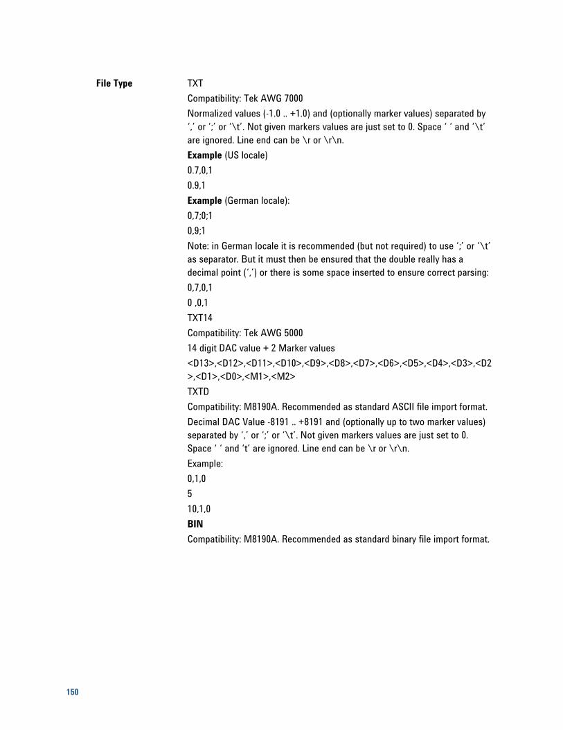
150
File Type TXT
Compatibility: Tek AWG 7000
Normalized values (-1.0 .. +1.0) and (optionally marker values) separated by
‘,’ or ‘;’ or ‘\t’. Not given markers values are just set to 0. Space ‘ ‘ and ‘\t’
are ignored. Line end can be \r or \r\n.
Example (US locale)
0.7,0,1
0.9,1
Example (German locale):
0,7;0;1
0,9;1
Note: in German locale it is recommended (but not required) to use ‘;’ or ‘\t’
as separator. But it must then be ensured that the double really has a
decimal point (‘,’) or there is some space inserted to ensure correct parsing:
0,7,0,1
0 ,0,1
TXT14
Compatibility: Tek AWG 5000
14 digit DAC value + 2 Marker values
<D13>,<D12>,<D11>,<D10>,<D9>,<D8>,<D7>,<D6>,<D5>,<D4>,<D3>,<D2
>,<D1>,<D0>,<M1>,<M2>
TXTD
Compatibility: M8190A. Recommended as standard ASCII file import format.
Decimal DAC Value -8191 .. +8191 and (optionally up to two marker values)
separated by ‘,’ or ‘;’ or ‘\t’. Not given markers values are just set to 0.
Space ‘ ‘ and ‘t’ are ignored. Line end can be \r or \r\n.
Example:
0,1,0
5
10,1,0
BIN
Compatibility: M8190A. Recommended as standard binary file import format.
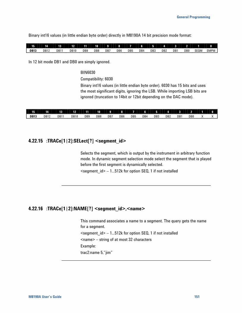
General Programming
M8190A User’s Guide 151
Binary int16 values (in little endian byte order) directly in M8190A 14 bit precision mode format:
15 14 13 12 11 10 9 8 7 6 5 4 3 2 1 0
DB13 DB12 DB11 DB10 DB9 DB8 DB7 DB6 DB5 DB4 DB3 DB2 DB1 DB0 SEQM SMPM
In 12 bit mode DB1 and DB0 are simply ignored.
BIN6030
Compatibility: 6030
Binary int16 values (in little endian byte order). 6030 has 15 bits and uses
the most significant digits, ignoring the LSB. While importing LSB bits are
ignored (truncation to 14bit or 12bit depending on the DAC mode).
15 14 13 12 11 10 9 8 7 6 5 4 3 2 1 0
DB13 DB12 DB11 DB10 DB9 DB8 DB7 DB6 DB5 DB4 DB3 DB2 DB1 DB0 X X
4.22.15 :TRACe[1|2]:SELect[?] <segment_id>
Selects the segment, which is output by the instrument in arbitrary function
mode. In dynamic segment selection mode select the segment that is played
before the first segment is dynamically selected.
<segment_id> – 1...512k for option SEQ, 1 if not installed
4.22.16 :TRACe[1|2]:NAME[?] <segment_id>,<name>
This command associates a name to a segment. The query gets the name
for a segment.
<segment_id> – 1...512k for option SEQ, 1 if not installed
<name> – string of at most 32 characters
Example:
trac2:name 5,”jim”
152
4.22.17 :TRACe[1|2]:COMMent[?] <segment_id>,<comment>
This command associates a comment to a segment. The query gets the
comment for a segment.
<segment_id> – 1...512k for option SEQ, 1 if not installed
<comment> – string of at most 256 characters
Example:
trac2:comm 5,”any information that should be associated with this
segment”
4.22.18 :TRACe[1|2]:ADVance[?] AUTO|CONDitional|REPeat|SINGle
Use this command or query to set or get the advancement mode for the
selected segment. The advancement mode is used, if the segment is played
in arbitrary mode.
4.22.19 :TRACe[1|2]:COUNt[?] <count>
Use this command or query to set or get the segment loop count for the
selected segment. The segment loop count is used, if the segment is played
in arbitrary mode.
<count> – 1..4G-1: number of times the selected segment is repeated.
4.22.20 :TRACe[1|2]:MARKer[:STATe][?] 0|1|ON|OFF
Use this command to enable or disable markers for the selected segment.
The query form gets the current marker state.
General Programming
M8190A User’s Guide 153
4.23 :TEST Subsystem
4.23.1 :TEST:PON?
Return the results of the power on self-tests.
4.23.2 :TEST:TST?
Same as , but the actual test messages are returned.
Note: currently same as
4.24 Example Programs
Example programs can be found in your installation of the M8190 software.

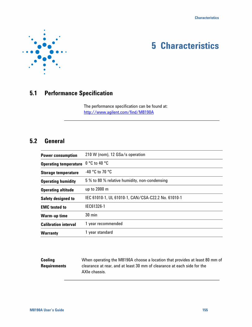
Characteristics
M8190A User’s Guide 155
5 Characteristics
5.1 Performance Specification
The performance specification can be found at:
http://www.agilent.com/find/M8190A
5.2 General
Power consumption 210 W (nom), 12 GSa/s operation
Operating temperature 0 °C to 40 °C
Storage temperature -40 °C to 70 °C
Operating humidity 5 % to 80 % relative humidity, non-condensing
Operating altitude up to 2000 m
Safety designed to IEC 61010-1, UL 61010-1, CAN/CSA-C22.2 No. 61010-1
EMC tested to IEC61326-1
Warm-up time 30 min
Calibration interval 1 year recommended
Warranty 1 year standard
Cooling
Requirements
When operating the M8190A choose a location that provides at least 80 mm of
clearance at rear, and at least 30 mm of clearance at each side for the
AXIe chassis.

© Copyright Agilent Technologies 2012
Third edition, July 2012
Printed in Germany


![RESEARCH SUMMARY - uni-hamburg.de · classes [15, 16] – differential trivializations of arbitary universal characteristic classes. We re-cover the canonical 3-forms [13] that are](https://static.fdocuments.us/doc/165x107/5f0cca357e708231d4372463/research-summary-uni-classes-15-16-a-differential-trivializations-of-arbitary.jpg)


![Originally published in: Research Collection Rights ...49863/... · scribed extension by a 12 GS/s AWG (Agilent M8190A) [30]. The temperature was 10 K and the repetition rate of the](https://static.fdocuments.us/doc/165x107/5b9412d609d3f2e5688c1ba1/originally-published-in-research-collection-rights-49863-scribed-extension.jpg)