
AGA TOTAL CONTROL Model No. - TC3 & TC5
20
11/15 EINS 516442 PLEASE READ THESE INSTRUCTIONS BEFORE COMMENCING SITE SURVEY OR INSTALLING THIS APPLIANCE. REMEMBER: when replacing a part on this appliance, use only spare parts that you can be assured conform to the safety and performance specification that we require. Do not use reconditioned or copy parts that have not been clearly authorised by AGA. AUSTRALIA Installation Guide AGA TOTAL CONTROL Model No. - TC3 & TC5
Transcript of AGA TOTAL CONTROL Model No. - TC3 & TC5

11/15 EINS 516442
PLEASE READ THESE INSTRUCTIONS BEFORE COMMENCING SITE SURVEYOR INSTALLING THIS APPLIANCE.
REMEMBER: when replacing a part on this appliance, use only spare parts thatyou can be assured conform to the safety and performance specification that we
require. Do not use reconditioned or copy parts that have not been clearlyauthorised by AGA.
AUSTRALIA
InstallationGuide
AGA TOTAL CONTROLModel No. - TC3 & TC5

SECTION PAGEHEALTH AND SAFETY 3INSTALLATION REQUIREMENTS 3DELIVERY REQUIREMENTS 3APPLIANCE DIMENSIONS - AGA TC3 4APPLIANCE DIMENSIONS - AGA TC5 (HOTCUPBOARD) 5CLEARANCES 6POWER SUPPLY - AGA TC3 7POWER SUPPLY - AGA TC5 (HOTCUPBOARD) 7
MAINS CABLE ROUTING - AGA TC3 8MAINS CABLE ROUTING - AGA TC5 (HOTCUPBOARD) 9VENT PIPE CONNECTION - AGA TC3 10OVEN VENTING SYSTEM - AGA TC3 11HOTCUPBOARD INSTALLATION 12HANDRAIL CONNECTION - AGA TC3 17WIRING DIAGRAM - AGA TC3 18WIRING DIAGRAM - AGA TC5 (HOTCUPBOARD) 19
2
CONTENTS

HEALTH AND SAFETYConsumer ProtectionAs responsible manufacturers we take care to make sure that our products are designed andconstructed to meet the required safety standards when properly installed and used.PLEASE READ THE ACCOMPANYING WARRANTY.Any alteration that is not approved by AGA could invalidate the approval of the appliance,operation of the warranty and could also affect your statutory rights.In the interests of safety and effective use, please read the following before using your new AGAappliance.ImportantThis appliance may contain some of the materials that are indicated below. It is theUsers/Installers responsibility to ensure that the necessary personal protective clothing is wornwhen handling, where applicable, the pertinent parts that contain any of the listed materials thatcould be interpreted as being injurious to health and safety, see below for information.Fire Cement - when handling use disposable gloves.Glues and Sealants - exercise caution - if these are still in liquid form use face mask anddisposable gloves.Glass Yarn, Mineral Wool, Insulation Pads - may be harmful if inhaled, may be irritating toskin, eyes, nose and throat. When handling avoid inhaling or contact with skin or eyes. Usedisposable gloves, face masks and eye protection. After handling wash hands and otherexposed parts. When disposing of the product, reduce dust with water spray, ensure that partsare securely wrapped.
INSTALLATION REQUIREMENTSTHIS APPLIANCE MUST ONLY BE INSTALLED BY COMPETENT ENGINEERS WHO HAVEBEEN SPECIFICALLY FACTORY TRAINED ON THE PRODUCT AND WHO HAVE THEAPPROPRIATE EQUIPMENT.Installation must be to Local and National Wiring Regulations/Codes in force, and carried out bya Qualified Engineer.Product Approval for Australia to AS/NZ 560335.2.6.
3
DELIVERY REQUIREMENTSThe AGA TC3 arrives on 1 palletThe AGA TC5 (Hotcupboard) arrives on 2 pallets.There must be access to the kitchen to manipulate a foot print of 1005mm x 740mm. A woodentemplate (skate with castor wheels) of dimensions 1005mm x 740mm could be used to check ifthe AGA Total Control fully built appliance is able to fit through the property grounds and doorsinto its installation position in the kitchen. It must also be considered that the height of theappliance is 960mm off pallet and 1100mm on the pallet, so high level obstacles/restrictions mustnot be overlooked.
If this skate/template can be manipulated through the property grounds and doorsinto position, then the AGA Total Control can be installed as intended with no re-work.

4
Fig. 1 DESN 516358 A
Cooker DimensionsWhen surveying for a cooker installation the actual clearance required for the ‘body’ of theappliance should be increased by 10mm beyond the figures quoted above. This allows safemargin to take into account the natural dimensional variations found in major castings. Inparticular the width across the appliance recess could be critical.
RH SIDEOVEN VENT
OPTION
RH SIDE VIEW FRONT VIEW
LH SIDEOVEN VENTOPTION
LH SIDE VIEW
PLAN VIEW
MINIMUM WALL POSITION MINIMUM WALL POSITION
APPLIANCE WEIGHTModel: AGA Total Control (TC3) - 370kg
DATA PLATE LOCATED BEHIND BOTTOM PLINTH
REAR OVEN VENTPIPE POSITION
REAR OVEN VENTPIPE POSITION
DATA PLATE LOCATEDBEHIND PLINTH
APPLIANCE DIMENSIONS - AGA TC3
Fig. 1 DESN 516358 A
RH SIDEOVEN VENT
OPTION
RH SIDE VIEW FRONT VIEW
LH SIDEOVEN VENTOPTION
LH SIDE VIEW
PLAN VIEW
MINIMUM WALL POSITION MINIMUM WALL POSITION
A B C D E F G H J K L M N P Q Rmm 987 951 913 680 1388 760 1145 698 116 10 536 813 30 634 448 824
REAR OVEN VENTPIPE POSITION
REAR OVEN VENTPIPE POSITION

Fig. 2 DESN 516445
Cooker DimensionsWhen surveying for a cooker installation the actual clearance required for the ‘body’ of theappliance should be increased by 10mm beyond the figures quoted above. This allows safemargin to take into account the natural dimensional variations found in major castings. Inparticular the width across the appliance recess could be critical.APPLIANCE WEIGHTModel: AGA Total Control (TC3) - 370kgHotcupboard - 110kg
A B C D E F G H J K L M N P Q Rmm 1478 951 913 680 1388 760 1145 698 116 10 536 824 30 634 448 813
DATA PLATE LOCATEDBEHIND PLINTH
5
REAR OVEN VENTPIPE POSITION
APPLIANCE DIMENSIONS - AGA TC5
RH SIDEOVEN VENT
OPTION
RH SIDE VIEW
FRONT VIEW
LH SIDEOVEN VENTOPTION
LH SIDE VIEW
PLAN VIEW
MINIMUM WALL POSITION
REAR OVEN VENTPIPE POSITION
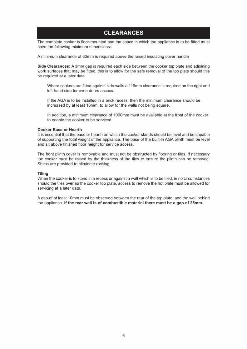
CLEARANCESThe complete cooker is floor-mounted and the space in which the appliance is to be fitted musthave the following minimum dimensions:-A minimum clearance of 60mm is required above the raised insulating cover handleSide Clearances: A 3mm gap is required each side between the cooker top plate and adjoiningwork surfaces that may be fitted, this is to allow for the safe removal of the top plate should thisbe required at a later date.
Where cookers are fitted against side walls a 116mm clearance is required on the right andleft hand side for oven doors access.If the AGA is to be installed in a brick recess, then the minimum clearance should be increased by at least 10mm, to allow for the walls not being square.In addition, a minimum clearance of 1000mm must be available at the front of the cooker to enable the cooker to be serviced.
Cooker Base or HearthIt is essential that the base or hearth on which the cooker stands should be level and be capableof supporting the total weight of the appliance. The base of the built-in AGA plinth must be leveland sit above finished floor height for service access.The front plinth cover is removable and must not be obstructed by flooring or tiles. If necessarythe cooker must be raised by the thickness of the tiles to ensure the plinth can be removed.Shims are provided to eliminate rocking.TilingWhen the cooker is to stand in a recess or against a wall which is to be tiled, in no circumstancesshould the tiles overlap the cooker top plate, access to remove the hot plate must be allowed forservicing at a later date.A gap of at least 10mm must be observed between the rear of the top plate, and the wall behindthe appliance. If the rear wall is of combustible material there must be a gap of 25mm.
6

POWER SUPPLY - AGA TC3WARNING: THIS APPLIANCE MUST BE EARTHED.THE APPLIANCE IS DESIGNED FOR THE VOLTAGE STATED ON THE RATING PLATE,WHICH IS SITUATED BEHIND THE PLINTH COVER.IF THE SUPPLY CORD IS DAMAGED, IT MUST BE REPLACED BY THE MANUFACTURER,ITS SERVICE AGENT OR SIMILARLY QUALIFIED PERSON TO AVOID A HAZARD.A 1PH 32 amp 230V or 3PH 400V minimum 16A per phase ~ 50 Hz fused electrical supply isrequired adjacent to the appliance. External wiring to the unit must be installed using the mainscable provided, in accordance with the current wiring regulations and any local regulations whichapply. If cable is shortened, new ferrules must be fitted to the stripped conductors.The method of connection to the mains electricity supply must facilitate complete electricalisolation of the appliance, by a multi-pole switch, having a contact separation of at least 3mm onall poles.The isolator should not be positioned immediately above the cooker. but must be fitted within 2metres of the appliance.The isolator maybe separate from the connection point.The mains connection point must be accessible within the area shown in Fig. 3A, Page 8 forcable routing options.For 2 or 3 phase installations an optional adaptor kit must be obtained (Part No. AE4M280354).
POWER SUPPLY - HOTCUPBOARD (AGA TC5)THE HOTCUPBOARD ATTACHMENT REQUIRES A INDEPEDENT SINGLE PHASE POWERSUPPLY.WARNING: THIS APPLIANCE MUST BE EARTHED.THIS APPLIANCE IS DESIGNED FOR THE VOLTAGE STATED ON THE RATING PLATE,WHICH IS SITUATED ON A SLIDE-OUT TRAY IN THE HOTCUPBOARD BASE PLATEABOVE THE PLINTH.IF THE SUPPLY CORD IS DAMAGED, IT MUST BE REPLACED BY THE MANUFACTURER,ITS SERVICE AGENT OR SIMILARLY QUALIFIED PERSON TO AVOID A HAZARD.A 230v ~ 50 Hz, 3 amp electrical supply is required to the appliance. External wiring to the unitmust be installed using the mains cable provided, in accordance with the current regulations andany local regulations which apply.The method of connection to the mains electricity supply must facilitate complete electricalisolation of the appliance, preferably by a fused double pole switch, having a contact separationof at least 3mm in both poles.The isolator should not be positioned immediately above the hotcupboard, but must be fitted with2 metres of the appliance.
7

MAINS CABLE ROUTING - AGA TC3
Fig. 3 DESN 516103
MAINS CABLE FED FROMCONTROL TRAY LEFT ORRIGHT EXIT THROUGHDUCTING DEPENDENT UPONPOSITION OF SUPPLY SOCKET
8Fig. 3A DESN 516105
THE MAINS SUPPLY CONNECT POINT MUST BE WITHIN THE ZONES SHOWN
MAINS CABLE ROUTING - AGA TC5 (HOTCUPBOARD)
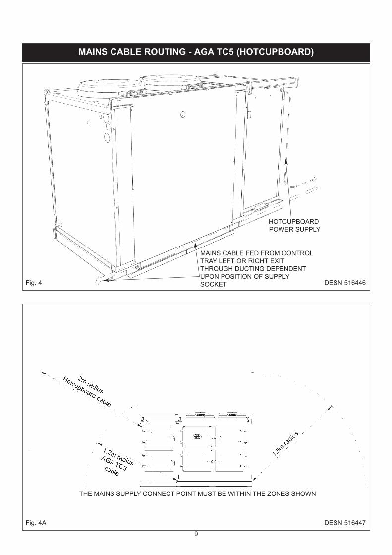
Fig. 4 DESN 516446
MAINS CABLE FED FROM CONTROLTRAY LEFT OR RIGHT EXITTHROUGH DUCTING DEPENDENTUPON POSITION OF SUPPLYSOCKET
9Fig. 4A DESN 516447
THE MAINS SUPPLY CONNECT POINT MUST BE WITHIN THE ZONES SHOWN
HOTCUPBOARDPOWER SUPPLY
VENT PIPE CONNECTION
10
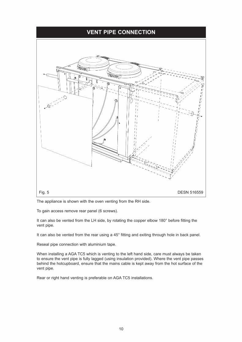
Fig. 5 DESN 516559The appliance is shown with the oven venting from the RH side. To gain access remove rear panel (6 screws).It can also be vented from the LH side, by rotating the copper elbow 180° before fitting thevent pipe.It can also be vented from the rear using a 45° fitting and exiting through hole in back panel.Reseal pipe connection with aluminium tape.When installing a AGA TC5 which is venting to the left hand side, care must always be takento ensure the vent pipe is fully lagged (using insulation provided). Where the vent pipe passesbehind the hotcupboard, ensure that the mains cable is kept away from the hot surface of thevent pipe.Rear or right hand venting is preferable on AGA TC5 installations.

OVEN VENTING SYSTEMSSee Fig. 6The appliance oven venting pipe can be achieved up to a maximum length of 6 metres, throughan outside wall. Great care must be taken in all-timber houses.If the oven vent pipe passes through combustible material, there must be an air gap of at least25mm around the pipe and preferably wrapped with insulation material.The max supply to the motor, as calculated should be limited to 22V (DC), for idealoperating conditions.Calculating the voltage for the particular pipework is as follows:-1. Keep the pipe run as simple as possible - avoid bends.2. “Vertical risers” are not permitted.3. Pipe run should be horizontal - slight downwards slope towards the fan.Minimum 12 volts for first metre of vent pipe run inclusive of 1 bendEach extra metre add 1 volt.Each extra bend add 2 voltsMaximum allowed 22 volts. Minimum setting is 15 volts.NOTE: IN THE OVEN VENTING, PROVISION MUST BE MADE FOR EASY ‘RODDING’ OFTHE PIPEWORK TO FACILITATE CLEANING.
11
Fig. 6 DESN 516111
HOTCUPBOARD INSTALLATION
Fig. 7 DESN 516448
Fig. 8 DESN 51644912
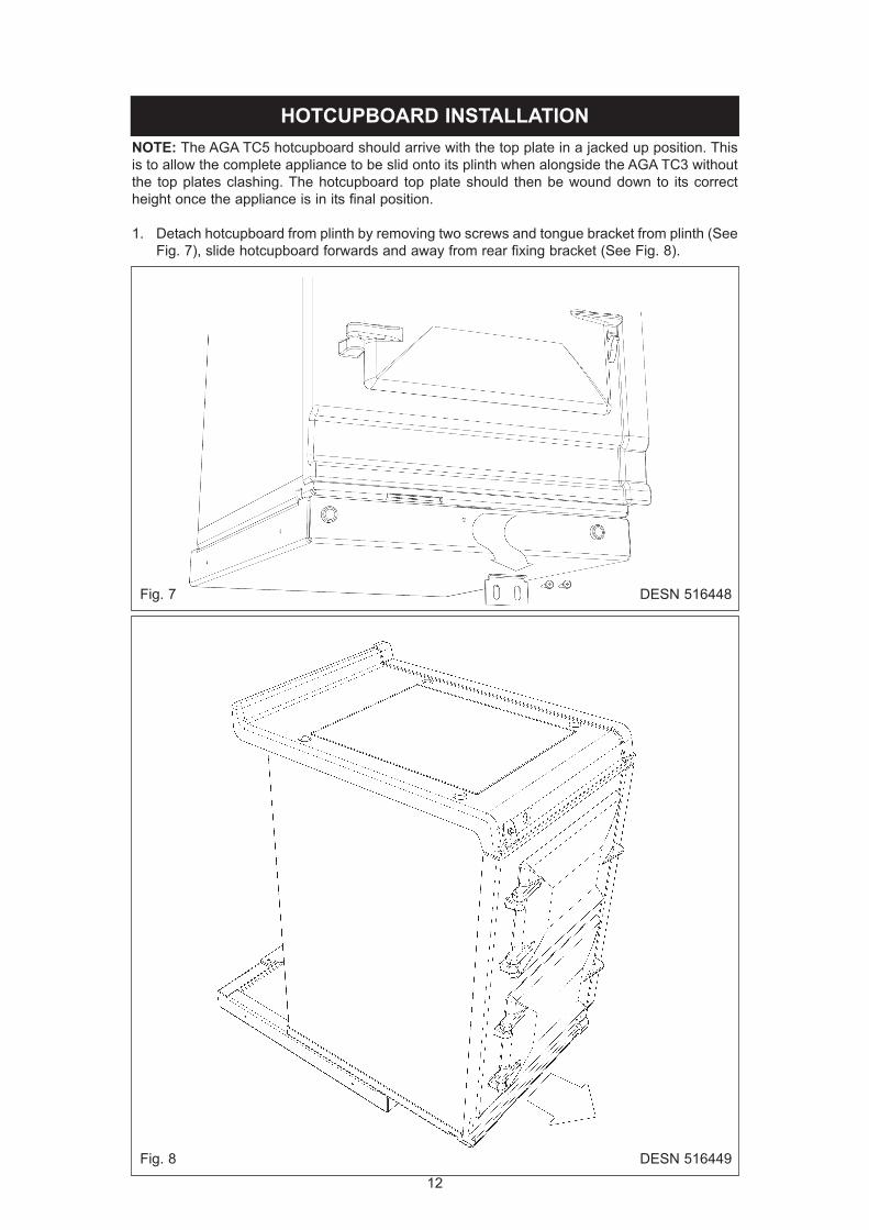
NOTE: The AGA TC5 hotcupboard should arrive with the top plate in a jacked up position. Thisis to allow the complete appliance to be slid onto its plinth when alongside the AGA TC3 withoutthe top plates clashing. The hotcupboard top plate should then be wound down to its correctheight once the appliance is in its final position.1. Detach hotcupboard from plinth by removing two screws and tongue bracket from plinth (See
Fig. 7), slide hotcupboard forwards and away from rear fixing bracket (See Fig. 8).

2. Position the plinth alongside the AGA Total Control leaving no gap between the two plinths (See Fig. 9).Check with a spirit level that the plinth level is correct, and also check height differential between the hotcupboard plinth and Total Control plinth is correct (11mm). If necessary, useshims in each corner to level the plinth.
Fig. 9 DESN 516276
HOTCUPBOARDPLINTH BASE
11mm HEIGHTDIFFERENTIAL
3. Attach hotcupboard plinth to the AGA Total Control plinth using M6 screws and washers provided (See Fig. 10).Attach locking screw and jacking screw into plinth. Make sure at this stage that the jacking screw does not protrude beyond outer face of plinth. Ensure locking screw is located into AGA TC3 plinth but not fully tightened. A gap of approximately 3mm should be present between the plinths apart from at the very front where the hotcupboard spacer plate shouldbe touching the AGA TC3 plinth.
Fig. 10 DESN 51655013
+1- 0

4. Run a straight edge along the front of the AGA Total Control plinth, to ensure the front face of both plinths sit squarely against the straight edge. (See Fig. 11)When satisfied both plinths sit squarely, jacking screws can be tightened until they just makecontact with the AGA Total Control plinth, and locking screws can now be tightened.
Fig. 11 DESN 516551USE STRAIGHT EDGE ACROSS BOTH PLINTHS TO ENSURE PLINTHSARE ALIGNED SQUARELY
Fig. 12 DESN 51655314
5. Front jointing bracket can now be hooked into place over the two pot magnets. This will latchthe two plinths together. (See Fig. 12)

Fig. 13 DESN 5165527. The hotcupboard top plate is set 5mm higher than the AGA Total Control top plate. This is to
prevent damage to the enamel during installation. Lower the top plate using the adjusters (See Figs. 14 and 15).
Fig. 14 DESN 51655415
6. Slide hotcupboard onto plinth until rear tongue bracket engages fully into rear of base slot, (See Fig. 13). Ensure the appliance is aligned squarely with the plinth then proceed to engage the front tongue bracket into the slot on the underside of the base plate. Once satisfied that the front tongue bracket is engaged fully lock it into place by tightening the twoM6 screws fully. Ensure that the electrical cable does not come into contact with oven vent pipe from the AGA TC3.

8. Using the stay rod nut adjusting tool, carefully lower the top plate adjusting nuts until the topplate sits at the required height, making sure that the top sits level and matches the height ofthe AGA TC3. (See Fig. 15). For servicing requirement, top plate should be removed by raising adjusters approximately 5mm, the top plate can now be removed easily without causing damage to the enamelled surfaces.When removing the top plate, the switch wiring harness should be disconnected from the main wiring harness at the connection point located at the front left hand side of the appliance, beneath the formex cover sheet
Fig. 15 DESN 516555
16
9. Slide the complete handrail assembly over the left hand and centre fixing studs. Once the assembly has been fitted to the AGA appliance, fit the handrail endcaps (ensuring the handrail is evenly spaced at each end). The endcaps should be carefully pushed into place until they sit flush with the outside face of each bracket. (A light smear of lubricant, such as washing up liquid can be applied to the end cap rubber ‘O’ rings to aid fitment of endcaps intohandrail if required).The handrail can now be locked into place using the grub screws on the underside of the handrail brackets.Finally fit plinth facia onto magnets positioned on plinth, ensuring the facia sits squarely andcentrally.
.

17
HANDRAIL CONNECTION - AGA TC3
Fig. 17 DESN 516560Handrail brackets, endcaps and handrail require assembly.Locate endcaps onto handrail, place brackets over endcaps and then slide complete assemblyonto locating studs.Once assembly is correctly located, lock into position with grub screws (located on undersideof handrail).
Fig. 16 DESN 516557
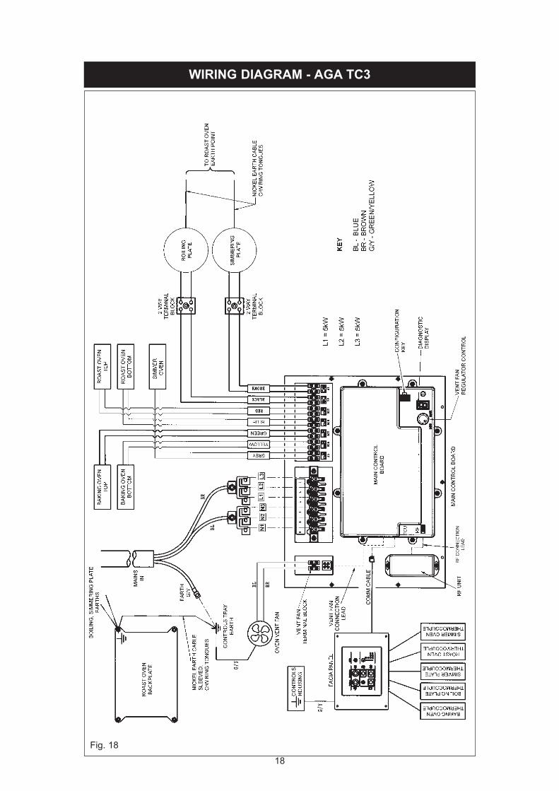
WIRING DIAGRAM - AGA TC3
18Fig. 18

19
Fig. 19
WIRING DIAGRAM - AGA TC5 (HOTCUPBOARD)
COLOUR KEYSBR - BROWNBL - BLUEGR - GREENOR - ORANGEBK - BLACK
CAUTION: LABEL ALL WIRES PRIOR TODISCONNECTION, WHEN SERVICING CONTROLSWIRING ERRORS CAN CAUSE IMPROPER ANDDANGEROUS OPERATION.VERIFY PROPER OPERATION AFTER SERVICING

20
With AGA Rangemaster’s policy of continuousproduct improvement, the Company reserves the
right to change specifications and makemodifications to the appliance described and
illustrated at any time
Manufactured byAGA Rangemaster
Station RoadKetley Telford
Shropshire TF1 5AQEngland
AGAaustralia.com.au03 9521 4965