
Manual TC3 Modbus TCP
61
Manual TC3 Modbus TCP TwinCAT 3 1.2 2016-09-20 TF6250 Version: Date: Order No.:
Transcript of Manual TC3 Modbus TCP

Manual
TC3 Modbus TCP
TwinCAT 3
1.22016-09-20TF6250
Version:Date:Order No.:


Table of contents
Table of contents1 Foreword .................................................................................................................................................... 4
1.1 Notes on the documentation............................................................................................................. 41.2 Safety instructions ............................................................................................................................ 5
2 Overview..................................................................................................................................................... 6
3 Installation.................................................................................................................................................. 73.1 System Requirements ...................................................................................................................... 73.2 Installation......................................................................................................................................... 73.3 Installation Windows CE ................................................................................................................. 103.4 Licensing......................................................................................................................................... 12
4 Configuration ........................................................................................................................................... 174.1 Overview......................................................................................................................................... 174.2 TwinCAT Modbus TCP Configurator .............................................................................................. 174.3 Mapping between Modbus and ADS .............................................................................................. 18
5 Diagnosis ................................................................................................................................................. 205.1 Modbus ADS Diagnosis Interface................................................................................................... 20
6 PLC libraries ............................................................................................................................................ 216.1 Overview......................................................................................................................................... 216.2 Function blocks............................................................................................................................... 21
6.2.1 FB_MBReadCoils (Modbus function 1)............................................................................... 216.2.2 FB_MBReadInputs (Modbus function 2)............................................................................. 236.2.3 FB_MBReadRegs (Modbus function 3) .............................................................................. 256.2.4 FB_MBReadInputRegs (Modbus function 4) ...................................................................... 276.2.5 FB_MBWriteSingleCoil (Modbus function 5)....................................................................... 296.2.6 FB_MBWriteSingleReg (Modbus function 6) ...................................................................... 316.2.7 FB_MBWriteCoils (Modbus function 15)............................................................................. 326.2.8 FB_MBWriteRegs (Modbus function 16) ............................................................................ 346.2.9 FB_MBReadWriteRegs (Modbus-Funktion 23) .................................................................. 366.2.10 FB_MBDiagnose (Modbus function 8) ................................................................................ 386.2.11 UDP .................................................................................................................................... 40
6.3 Global constants ............................................................................................................................. 536.3.1 Library Version.................................................................................................................... 53
7 Samples.................................................................................................................................................... 557.1 Sample: Digital IO access............................................................................................................... 557.2 Sample: Multiple register access .................................................................................................... 56
8 Appendix .................................................................................................................................................. 578.1 Overview......................................................................................................................................... 578.2 ADS Return Codes ......................................................................................................................... 57
TC3 Modbus TCP 3Version: 1.2

Foreword
1 Foreword
1.1 Notes on the documentationThis description is only intended for the use of trained specialists in control and automation engineering whoare familiar with the applicable national standards.It is essential that the following notes and explanations are followed when installing and commissioningthese components.
The responsible staff must ensure that the application or use of the products described satisfy all therequirements for safety, including all the relevant laws, regulations, guidelines and standards.
DisclaimerThe documentation has been prepared with care. The products described are, however, constantly underdevelopment.For that reason the documentation is not in every case checked for consistency with performance data,standards or other characteristics.In the event that it contains technical or editorial errors, we retain the right to make alterations at any timeand without warning.No claims for the modification of products that have already been supplied may be made on the basis of thedata, diagrams and descriptions in this documentation.
TrademarksBeckhoff®, TwinCAT®, EtherCAT®, Safety over EtherCAT®, TwinSAFE®, XFC®and XTS® are registeredtrademarks of and licensed by Beckhoff Automation GmbH.Other designations used in this publication may be trademarks whose use by third parties for their ownpurposes could violate the rights of the owners.
Patent PendingThe EtherCAT Technology is covered, including but not limited to the following patent applications andpatents:EP1590927, EP1789857, DE102004044764, DE102007017835with corresponding applications or registrations in various other countries.
The TwinCAT Technology is covered, including but not limited to the following patent applications andpatents:EP0851348, US6167425 with corresponding applications or registrations in various other countries.
EtherCAT® is registered trademark and patented technology, licensed by Beckhoff Automation GmbH,Germany
Copyright© Beckhoff Automation GmbH & Co. KG, Germany.The reproduction, distribution and utilization of this document as well as the communication of its contents toothers without express authorization are prohibited.Offenders will be held liable for the payment of damages. All rights reserved in the event of the grant of apatent, utility model or design.
TC3 Modbus TCP4 Version: 1.2

Foreword
1.2 Safety instructions
Safety regulationsPlease note the following safety instructions and explanations!Product-specific safety instructions can be found on following pages or in the areas mounting, wiring,commissioning etc.
Exclusion of liabilityAll the components are supplied in particular hardware and software configurations appropriate for theapplication. Modifications to hardware or software configurations other than those described in thedocumentation are not permitted, and nullify the liability of Beckhoff Automation GmbH & Co. KG.
Personnel qualificationThis description is only intended for trained specialists in control, automation and drive engineering who arefamiliar with the applicable national standards.
Description of symbolsIn this documentation the following symbols are used with an accompanying safety instruction or note. Thesafety instructions must be read carefully and followed without fail!
DANGER
Serious risk of injury!Failure to follow the safety instructions associated with this symbol directly endangers thelife and health of persons.
WARNING
Risk of injury!Failure to follow the safety instructions associated with this symbol endangers the life andhealth of persons.
CAUTION
Personal injuries!Failure to follow the safety instructions associated with this symbol can lead to injuries topersons.
Attention
Damage to the environment or devicesFailure to follow the instructions associated with this symbol can lead to damage to the en-vironment or equipment.
Note
Tip or pointerThis symbol indicates information that contributes to better understanding.
TC3 Modbus TCP 5Version: 1.2
Overview
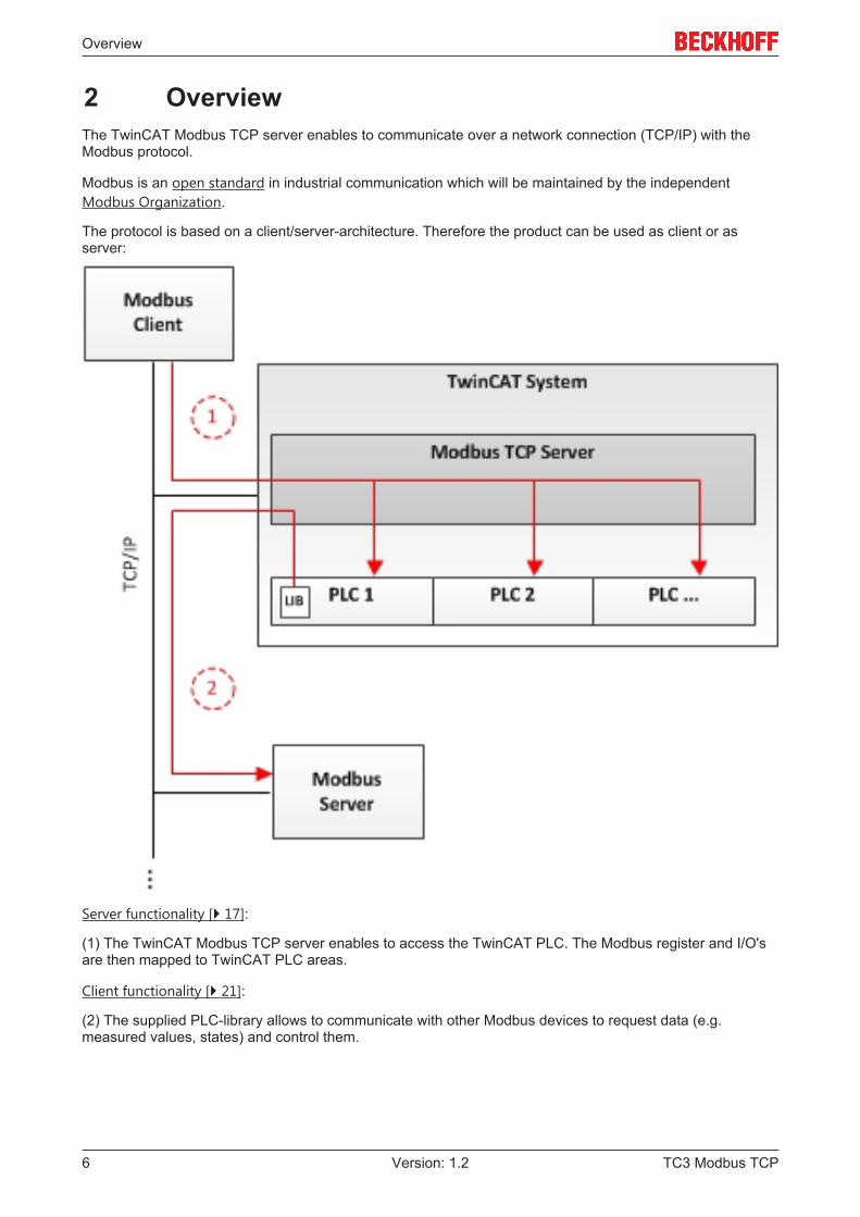
2 OverviewThe TwinCAT Modbus TCP server enables to communicate over a network connection (TCP/IP) with theModbus protocol.
Modbus is an open standard in industrial communication which will be maintained by the independentModbus Organization.
The protocol is based on a client/server-architecture. Therefore the product can be used as client or asserver:
Server functionality [} 17]:
(1) The TwinCAT Modbus TCP server enables to access the TwinCAT PLC. The Modbus register and I/O'sare then mapped to TwinCAT PLC areas.
Client functionality [} 21]:
(2) The supplied PLC-library allows to communicate with other Modbus devices to request data (e.g.measured values, states) and control them.
TC3 Modbus TCP6 Version: 1.2

Installation
3 Installation
3.1 System RequirementsTechnical Data TF6250 TwinCAT 3 Modbus TCP ServerTarget System Windows NT/2000/XP/Vista/7
PC (x86-compatible)Min. TwinCAT-Version 3.0.0Min. TwinCAT-Level TC1200 TC3 | PLC
Requirements
Development environment Target system type PLC libraries to be linkedTwinCAT v3.0.0 PC or CX (x86, ARM) Tc2_ModbusSrv
3.2 InstallationDescription of the installation procedure of a TwinCAT 3 Function for Windows-based operating Systems.
1. Double-click the downloaded setup file "TE1610 TC3 EAP-Configurator.exe".Please note: Under Windows 32-bit/64-bit, please start the installation with "Run as Administrator" byright-clicking the setup file and selecting the corresponding option in the context menu.
2. Click on "Next" and accept the license Agreement.
TC3 Modbus TCP 7Version: 1.2
Installation
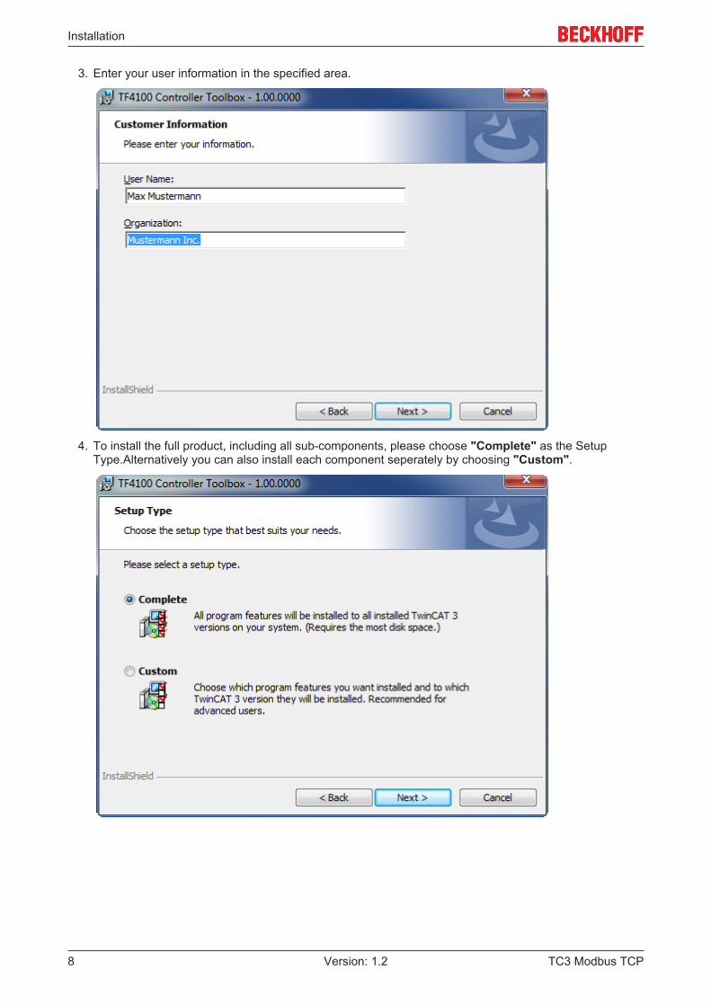
3. Enter your user information in the specified area.
4. To install the full product, including all sub-components, please choose "Complete" as the SetupType.Alternatively you can also install each component seperately by choosing "Custom".
TC3 Modbus TCP8 Version: 1.2
Installation
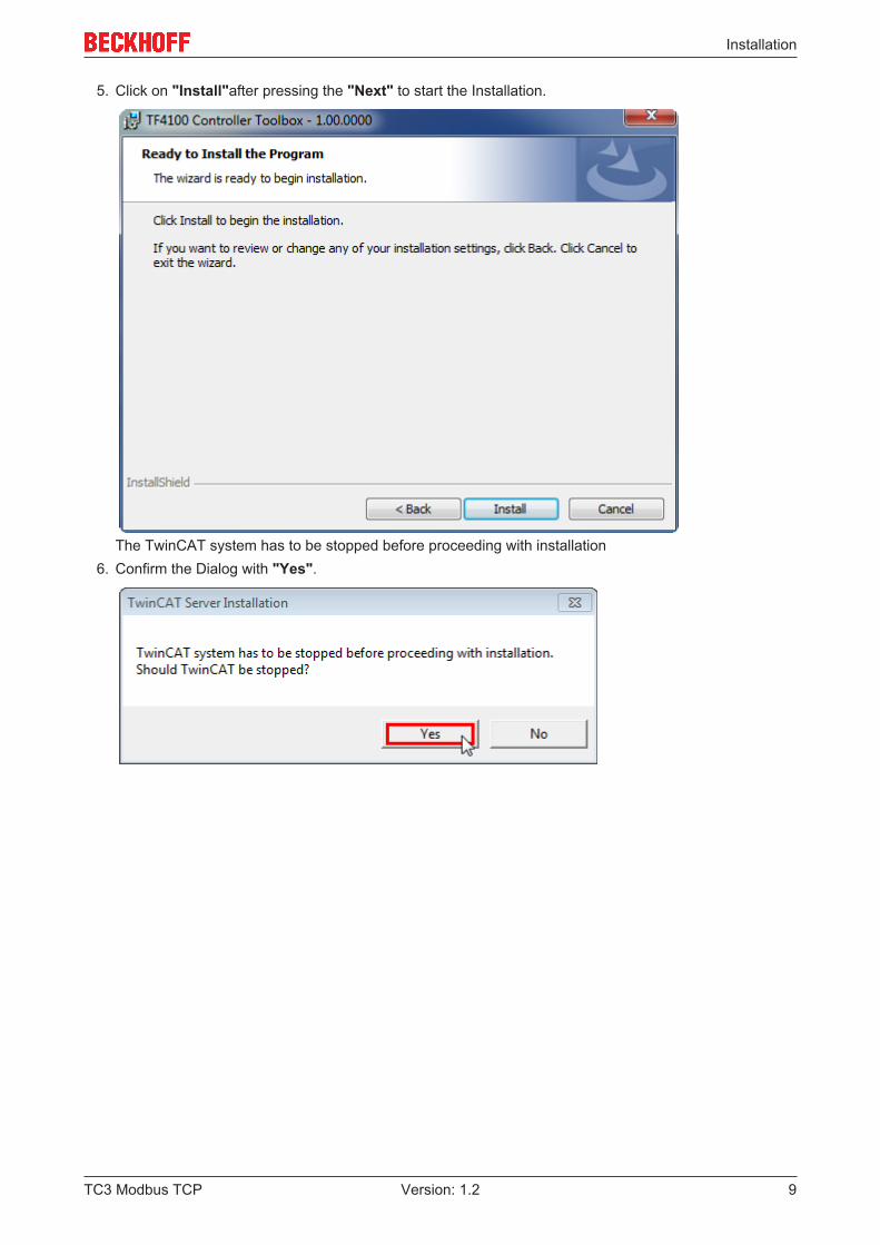
5. Click on "Install"after pressing the "Next" to start the Installation.
The TwinCAT system has to be stopped before proceeding with installation6. Confirm the Dialog with "Yes".
TC3 Modbus TCP 9Version: 1.2

Installation
7. Select "Finish" to end the installation process.
ð The installation is complete now.
After a successful installation the TC 3 Function needs to be licensed [} 12]
3.3 Installation Windows CEThis part of the documentation describes, how you can install the TwinCAT 3 Function TF6310 TCP/IP on aBeckhoff Embedded PC Controller based on Windows CE.
The setup process consists of four steps:
1. Downloading the setup file2. Installation on a host computer3. Transfering the executable to the Windows CE device4. Software installation
The last paragraph describes the Software upgrade
Downloading the setup fileThe CAB installation file for Windows CE is part of the TFxxxx setup. Therefore you only need to downloadone setup file from www.beckhoff.com which contains binaries for Windows XP, Windows 7 and WindowsCE (x86 and ARM).
Installation on a host computerAfter installation, the install folder contains three directories - each one for a different hardware platform:
• CE-ARM: ARM-based Embedded Controllers running Windows CE, e.g. CX8090, CX9020• CE-X86: X86-based Embedded Controllers running Windows CE, e.g. CX50xx. CX20x0• Win32: Embedded Controllers running Windows XP, Windows 7 or Windows Embedded Standard
TC3 Modbus TCP10 Version: 1.2

Installation
The CE-ARM and CE-X86 folders contain the TFxxx ( here TF6310) CAB-File for Windows CE -corresponding to the hardware platform of your Windows CE device. This file needs to be transfered to theWindows CE device.
Transfering the executable to the Windows CE deviceTransfer the corresponding executable to you Windows CE device. This can be done via one of the followingways:
• via a Shared Folder• via the integrated FTP-Server• via ActiveSync• via a CF/SD card
For more information, please consult the "Windows CE" section in our Infosys documentation system.
Software installationAfter the CAB-File has been transfered via one of the above methods, you need to execute the file andacknowledge the following dialog with "Ok". Restart your Windows CE device after the installation hasfinished.
After the restart has been completed, the TFxxxx executable files will be automatically started in backgroundand is now available to use.
The software will be installed in the following directory on the CE device: \Hard Disk\TwinCAT\Functions\TFxxxx
Upgrade instructionsIf you have already a version of TF6310 installed on your Windows CE device, you need to perform thefollowing things on the Windows CE device to upgrade to a newer version:
1. Open the CE Explorer by clicking on Start --> Run and entering "explorer"2. Navigate to \Hard Disk\TwinCAT\Functions\TFxxx\xxxx3. Rename the file “Tc*.exe” to “Tc*.old”4. Restart the Windows CE device5. Transfer the new CAB-File to the CE device6. Execute the CAB-File and install the new version7. Delete “Tc*.old.”8. Restart the Windows CE deviceð After the restart is complete, the new version is active.
TC3 Modbus TCP 11Version: 1.2

Installation
3.4 LicensingThe TwinCAT 3 functions are available both as a full and as a 7-Day trial version. Both license types can beactivated via TwinCAT XAE.For more information about TwinCAT 3 licensing, please consult the TwinCAT 3Help System.The following document describes both licensing scenarios for a TwinCAT 3 function onTwinCAT 3 and is divided into the following sections:
• Licensing a 7-Day trial version [} 12]
• Licensing a full version [} 13]
Licensing a 7-Day trial version1. Start TwinCAT XAE2. Open an existing TwinCAT 3 project or create a new project3. In “Solution Explorer”, please navigate to the entry “System\License”
4. Open the tab "Manage Licenses" and add a "Runtime License" for your product (in this screenshot“TE1300: TC3 Scope View Professional”)
5. Optional: If you would like to add a license for a remote device, you first need to connect to the remotedevice via TwinCAT XAE toolbar
TC3 Modbus TCP12 Version: 1.2
Installation
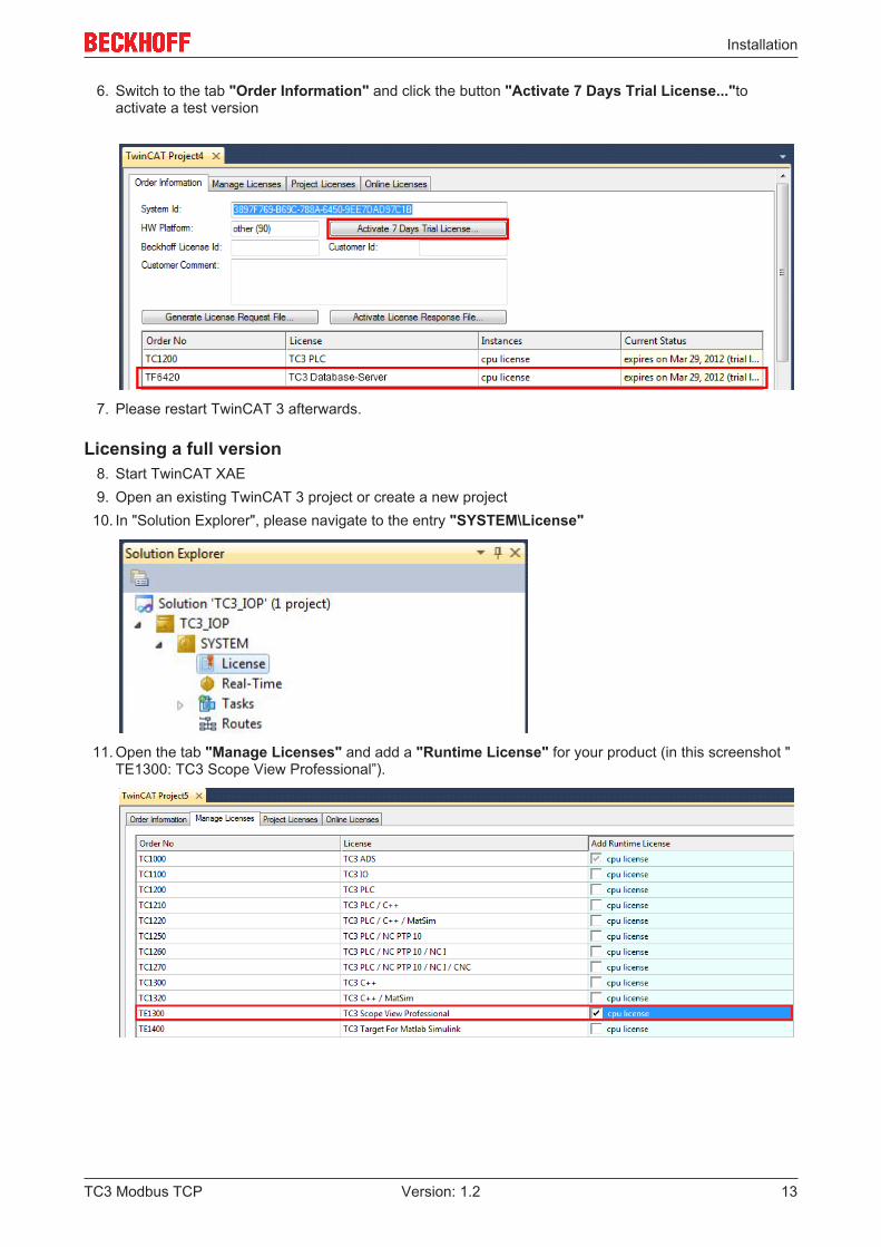
6. Switch to the tab "Order Information" and click the button "Activate 7 Days Trial License..."toactivate a test version
7. Please restart TwinCAT 3 afterwards.
Licensing a full version8. Start TwinCAT XAE9. Open an existing TwinCAT 3 project or create a new project
10. In "Solution Explorer", please navigate to the entry "SYSTEM\License"
11. Open the tab "Manage Licenses" and add a "Runtime License" for your product (in this screenshot "TE1300: TC3 Scope View Professional”).
TC3 Modbus TCP 13Version: 1.2

Installation
12. Optional:If you would like to add a license for a remote device, you first need to connect to the remotedevice via TwinCAT XAE toolbar
13. Navigate to the "Order Information" tabThe fields "System-ID" and "HW Platform" cannot be changed and just describe the platform for thelicensing process in general a TwinCAT 3 license is always bound to these two identifiers:the "System-ID" uniquely identifies your system.The "HW Platform" is an indicator for the performance of the device.
14. Optionally, you may also enter an own order number and description for your convenience
15. enter the "Beckhoff License ID" and click on "Generate License Request File...". If you are not awareof your "Beckhoff License ID" please contact your local sales representative.
16. After the license request file has been saved, the system asks whether to send this file via E-Mail to theBeckhoff Activation Server
17. After clicking "Yes", the standard E-Mail client opens and creates a new E-Mail message to"[email protected]" which contains the "License Request File"
18. Send this Activation Request to BeckhoffNOTE! The “License Response File“ will be sent to the same E-Mail address used for sending
out the ”License Request File”
TC3 Modbus TCP14 Version: 1.2
Installation
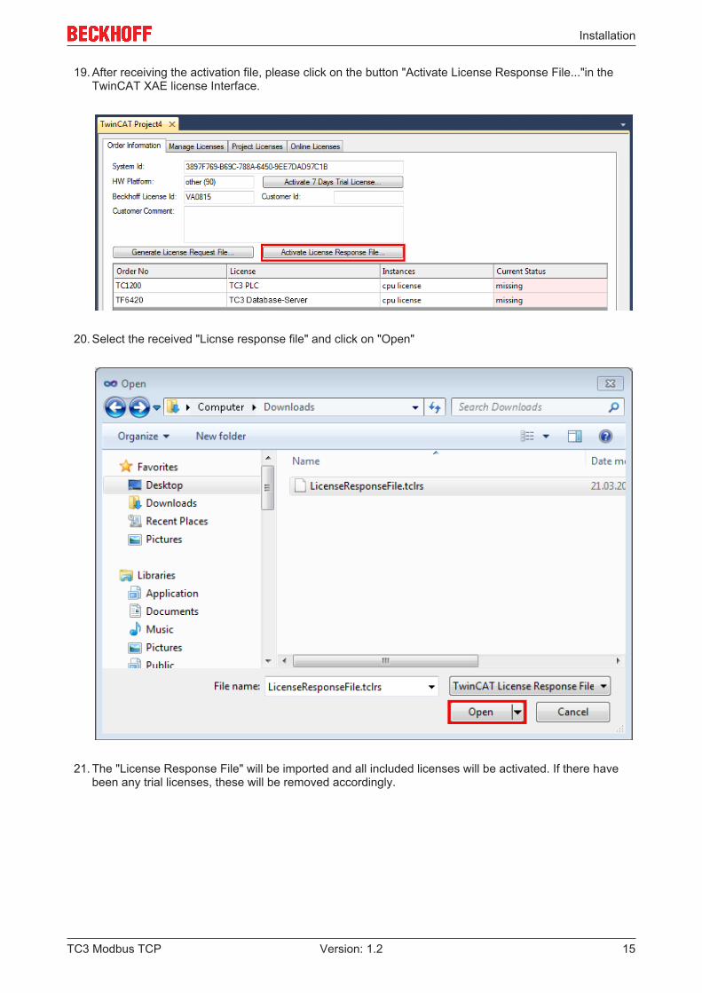
19. After receiving the activation file, please click on the button "Activate License Response File..."in theTwinCAT XAE license Interface.
20. Select the received "Licnse response file" and click on "Open"
21. The "License Response File" will be imported and all included licenses will be activated. If there havebeen any trial licenses, these will be removed accordingly.
TC3 Modbus TCP 15Version: 1.2

Installation
22. Please restart TwinCAT to activate licenses..
NOTE! The license file will be automatically copied to "..\TwinCAT\3.1\Target\License" on thelocal device.
TC3 Modbus TCP16 Version: 1.2

Configuration
4 Configuration
4.1 OverviewThe server can receive Modbus functions via TCP/IP.
Modbus-BereicheThe Modbus specification defines these four Modbus-areas:
Modbus-areas Data type Access Exampledigital inputs (DiscreteInputs)
1 Bit Read only
digitale outputs (Coils) 1 Bit Read / write
Input registers 16 Bit Read only
Output registers 16 Bit Read / write
After the installation the modbus areas are mapped to the PLC areas. Check the article about the default-mapping [} 18].
The TwinCAT Modbus TCP/IP server configurator [} 17] is used for configuring this mapping.
ADS-AccessIf you want to access the specific modbus areas, you have to add these global variables to your PLC project.VAR_GLOBALGVL.mb_Input_Coils : ARRAY [0..255] OF BOOL;GVL.mb_Output_Coils : ARRAY [0..255] OF BOOL;GVL.mb_Input_Registers : ARRAY [0..255] OF WORD;GVL.mb_Output_Registers : ARRAY [0..255] OF WORD;END_VAR
Requirements
Development environment Target system type PLC libraries to be linkedTwinCAT v3.0.0 PC or CX (x86) Tc2_ModbusSrv
4.2 TwinCAT Modbus TCP ConfiguratorThe configurator is installed per default to the directory \TwinCAT3\Functions\TF6250-Modbus-TCP. Thetools allows to read and change the actual configuration of TwinCAT Modbus TCP server.
TC3 Modbus TCP 17Version: 1.2

Configuration
IP Address: IP of the server. If no address is set, the local one is used (default) .
Port: Configured port of the server (default port = 502).
Get Configuration: Read configured IP address and port.
Set Configuration: Set IP address and port.
Export Configuration: Read and save configuration.
Import Configuration: Import new configuration.
Set Default Configuration: Reset to default-settings (use local ip, Port = 502, and default mapping [} 18]).
NOTE! TwinCAT must be stopped if you want to use the configurator, which will be done by thetool.
Export configurationThe configuration is XML-based and can be changed by a text editor. With "Export Configuration" the actualconfiguration can be stored local as XML-file.
NOTE! It is easier to edit and activate an exported configuration.
Import Mapping-InformationsWith "Import Configuration" a changed configuration can be imported and activated.
NOTE! It is possible to map by variablename or IndexGroup/Offset (better performance).
Windows CEThe standard configuration is in the TcModbusSrv.xml (path: \TwinCAT3\Functions\TF6250-Modbus-TCP\Server). If you change the settings in the file, a restart is necessary.
4.3 Mapping between Modbus and ADSThe default mapping is shown in the following table:
TC3 Modbus TCP18 Version: 1.2

Configuration
Modbus areas Modbus address ADS areaDigital inputs 0x0000 - 0x7FFF Index group Index offset
0xF031 - process imageof the physical inputs (bitaccess)
0xFA000
0x8000 - 0x80FF Name of the variables inthe PLC program
Data type
GVL.mb_Input_Coils ARRAY [0..255] OFBOOL
Digital outputs (coils) 0x0000 - 0x7FFF Index group Index offset0xF031 - process imageof the physical outputs (bitaccess)
0x1F4000
0x8000 - 0x80FF Name of the variables inthe PLC program
Data typw
GVL.mb_Output_Coils ARRAY [0..255] OFBOOL
Input registers 0x0000 - 0x7FFF Index group Index offset0xF030 - process imageof the physical inputs
0xFAFA0
0x8000 - 0x80FF Name of the variables inthe PLC program
Data typw
GVL.mb_Input_Registers ARRAY [0..255] OFWORD
Output registers 0x0000 - 0x2FFF Index group Index offset0xF030 - process imageof the physical outputs
0x3E800
0x3000 - 0x5FFF 0x4020 - PLC memoryarea
0x0
0x6000 - 0x7FFF 0x4040 - PLC data area 0x00x8000 - 0x80FF Name of the variables in
the PLC programData type
GVL.mb_Output_Registers
ARRAY [0..255] OFWORD
The server maps the individuals ADS areas and enables the access to the physical process image and mapsthe PLC data area.
The mapping can be adjusted by the TwinCAT Modbus TCP Configurator [} 17].
TC3 Modbus TCP 19Version: 1.2

Diagnosis
5 Diagnosis
5.1 Modbus ADS Diagnosis InterfaceModbus ADS diagnosis interface
Via ADS the following information can be monitored:
indexgroup
indexoffset
access
datatype
description minimal Modbusserver version
0x2000 0 ADSRead
UINT32 GetConnectedClientCountreturns the number ofconnected Modbus clients
1.0.50
0x2000 1 ADSRead
UINT32 GetModbusRequestCountreturns the received Modbusrequests
1.0.50
0x2000 2 ADSRead
UINT32 GetModbusResponseCountreturns the received Modbusanswers
1.0.50
TC3 Modbus TCP20 Version: 1.2

PLC libraries
6 PLC libraries
6.1 OverviewThe defined modbus functions are implemented in the PLC library TcModbusSrv.lib.
Modbus TCP function Function code PLC blockRead Coils 1 FB_MBReadCoils [} 21]Read Inputs 2 FB_MBReadInputs [} 23]Read Registers 3 FB_MBReadRegs [} 25]Read Input Registers 4 FB_MBReadInputRegs [} 27]Write Single Coil 5 FB_MBWriteSingleCoil [} 29]Write Single Register 6 FB_MBWriteSingleReg [} 31]Write Multiple Coils 15 FB_MBWriteCoils [} 32]Write Multiple Registers 16 FB_MBWriteRegs [} 34]Read/Write Multiple Registers 23 FB_MBReadWriteRegs [} 36]Diagnostic 8 FB_MBDiagnose [} 38]
Requirements
Development environment Target system type PLC libraries to be linkedTwinCAT v3.0.0 PC or CX (x86) Tc2_ModbusSrv
6.2 Function blocks
6.2.1 FB_MBReadCoils (Modbus function 1)
This function is used for reading 1 to 2048 digital outputs (coils). One digital output corresponds to one bit ofthe read data bytes.
VAR_INPUT
VAR_INPUT sIPAddr : STRING(15); nTCPPort : UINT:= MODBUS_TCP_PORT; nUnitID : BYTE:=16#FF; nQuantity : WORD;
TC3 Modbus TCP 21Version: 1.2

PLC libraries
nMBAddr : WORD; cbLength : UDINT; pDestAddr : POINTER OF BYTE; bExecute : BOOL; tTimeout : TIME;END_VAR
sIPAddr : Is a string containing the IP address of the target device.
nTCPPort : Port number of the target device.
nUnitID: Identification number of a serial sub-network device. If a device is addressed directly via TCP/IP,this value must be 16#FF.
nQuantity : Number of digital inputs (data bits) to be read. The value of nQuantity must be > 0.
nMBAddr : Start address of the digital inputs to be read (bit offset).
cbLength : Contains the max. byte size of the destination buffer into which the data are to be read. Theminimum buffer byte size must be: (nQuantity + 7) / 8.
pDestAddr : Contains the address of the destination buffer into which the data are to be read. The buffercan be a single variable, an array or a structure, whose address can be found with the ADR operator.
bExecute: The function block is activated by a rising edge at this input.
tTimeout: States the length of the timeout that may not be exceeded by execution of the ADS command.
VAR_OUTPUT
VAR_OUTPUT bBUSY : BOOL; bError : BOOL; nErrId : UDINT; cbRead : UDINT;END_VAR
bBusy : When the function block is activated this output is set. It remains set until an acknowledgement isreceived.
bError : If an ADS error should occur during the transfer of the command, then this output is set once thebBusy output is reset.
nErrId : Supplies the ADS error number [} 57] when the bError output is set.
cbRead: Contains the number of bytes currently read.
Function specific ADS error code Possible reason0x8001 Modbus function not implemented0x8002 Invalid address or length0x8003 Invalid parameters: - wrong number of registers0x8004 Modbus server error
Example of calling the block in FBD:
PROGRAM TestVAR fbReadCoils : FB_MBReadCoils; bReadCoils : BOOL; bReadCoilsBusy : BOOL; bReadCoilsError : BOOL; nReadCoilsErrorId: UDINT; nReadCoilsCount : UDINT; nQuantity : WORD := 10; nMBAddr : WORD := 5; arrData : ARRAY [1..2] OF BYTE;END_VAR
TC3 Modbus TCP22 Version: 1.2

PLC libraries
After a rising edge of "bExecute" and successful execution of the ReadCoils command, the content of digitaloutputs 6 - 15 is written into the arrData array:
Digital outputs Array offset Status6-13 1 0x54 The status of output 13 is the
MSB of this byte (left)The status of output 6 is the LSB ofthis byte (right)
14-15 2 0x02 Since only 10 outputs are tobe read, the remaining bits (3-8)are set to 0.
Requirements
Development environment Target system type PLC libraries to be linkedTwinCAT v3.0.0 PC or CX (x86) Tc2_ModbusSrv
6.2.2 FB_MBReadInputs (Modbus function 2)
This function is used for reading 1 to 2048 digital inputs. One digital input corresponds to one bit of the readdata bytes.
VAR_INPUT
VAR_INPUT sIPAddr : STRING(15); nTCPPort : UINT:= MODBUS_TCP_PORT; nUnitID : BYTE:=16#FF; nQuantity : WORD; nMBAddr : WORD;
TC3 Modbus TCP 23Version: 1.2

PLC libraries
cbLength : UDINT; pDestAddr : POINTER OF BYTE; bExecute : BOOL; tTimeout : TIME;END_VAR
sIPAddr: Is a string containing the IP address of the target device.
nTCPPort: Port number of the target device.
nUnitID: Identification number of a serial sub-network device. If a device is addressed directly via TCP/IP,this value must be 16#FF.
nQuantity: Number of digital inputs (data bits) to be read. The value of nQuantity must be > 0.
nMBAddr: Start address of the digital inputs to be read (bit offset).
cbLength: Contains the max. byte size of the destination buffer. The minimum buffer byte size must be:(nQuantity + 7) / 8.
pDestAddr: Contains the address of the destination buffer into which the data are to be read. The buffer canbe a single variable, an array or a structure, whose address can be found with the ADR operator.
bExecute: The function block is activated by a rising edge at this input.
tTimeout: States the length of the timeout that may not be exceeded by execution of the ADS command.
VAR_OUTPUT
VAR_OUTPUT bBUSY : BOOL; bError : BOOL; nErrId : UDINT; cbRead : UDINT;END_VAR
bBusy : When the function block is activated this output is set. It remains set until an acknowledgement isreceived.
bError : If an ADS error should occur during the transfer of the command, then this output is set once thebBusy output is reset.
nErrId : Supplies the ADS error number [} 57] when the bError output is set.
cbRead: Contains the number of bytes currently read.
Function specific ADS error code Possible reason0x8001 Modbus function not implemented0x8002 Invalid address or length0x8003 Invalid parameters: - wrong number of registers0x8004 Modbus server error
Example of calling the block in FBD:
PROGRAM TestVAR fbReadInputs : FB_MBReadInputs; bReadInputs : BOOL; bReadInputsBusy : BOOL; bReadInputsError : BOOL; nReadInputsErrorId : UDINT; nReadInputsCount : UDINT; nQuantity : WORD := 20; nMBAddr : WORD := 29; arrData : ARRAY [1..3] OF BYTE;END_VAR
TC3 Modbus TCP24 Version: 1.2

PLC libraries
After a rising edge of "bExecute" and successful execution of the ReadInputs command, the content of digitalinputs 30 - 49 is written into the arrData array:
Digital outputs Array offset Status29-36 1 0x34 The status of inputs 36 is the
MSB of this byte (left)The status of inputs 29 is the LSBof this byte (right)
37-44 2 0x56 The status of inputs 44 is theMSB of this byte (left)The status of inputs 37 is the LSBof this byte (right)
45-49 3 0x07 Since only 20 outputs are tobe read, the remaining bits (5-8)are set to 0.
Requirements
Development environment Target system type PLC libraries to be linkedTwinCAT v3.0.0 PC or CX (x86) Tc2_ModbusSrv
6.2.3 FB_MBReadRegs (Modbus function 3)
This function is used for reading 1 to 128 output registers (16 bit). The first byte contains the lower eight bitsand the second byte the upper eight bits.
VAR_INPUT
VAR_INPUT sIPAddr : STRING(15); nTCPPort : UINT:= MODBUS_TCP_PORT;
TC3 Modbus TCP 25Version: 1.2

PLC libraries
nUnitID : BYTE:=16#FF; nQuantity : WORD; nMBAddr : WORD; cbLength : UDINT; pDestAddr : POINTER OF BYTE; bExecute : BOOL; tTimeout : TIME;END_VAR
sIPAddr: Is a string containing the IP address of the target device.
nTCPPort: Port number of the target device.
nUnitID: Identification number of a serial sub-network device. If a device is addressed directly via TCP/IP,this value must be 16#FF.
nQuantity: Number of output registers (data words) to be read. The value of nQuantity must be > 0.
nMBAddr: Start address of the output registers to be read (word offset).
cbLength: Contains the max. byte size of the destination buffer. The minimum buffer byte size must be:nQuantity * 2.
pDestAddr: Contains the address of the destination buffer into which the data are to be read. The buffer canbe a single variable, an array or a structure, whose address can be found with the ADR operator.
bExecute: The function block is activated by a rising edge at this input.
tTimeout: States the length of the timeout that may not be exceeded by execution of the ADS command.
VAR_OUTPUT
VAR_OUTPUT bBUSY : BOOL; bError : BOOL; nErrId : UDINT; cbRead : UDINT;END_VAR
bBusy : When the function block is activated this output is set. It remains set until an acknowledgement isreceived.
bError : If an ADS error should occur during the transfer of the command, then this output is set once thebBusy output is reset.
nErrId : Supplies the ADS error number [} 57] when the bError output is set.
cbRead: Contains the number of bytes currently read.
Function specific ADS error code Possible reason0x8001 Modbus function not implemented0x8002 Invalid address or length0x8003 Invalid parameters: - wrong number of registers0x8004 Modbus server error
Example of calling the block in FBD:
PROGRAM TestVAR fbReadRegs : FB_MBReadRegs; bReadRegs : BOOL; bReadRegsBusy : BOOL; bReadRegsError : BOOL; nReadRegsErrorId: UDINT; nReadRegsCount : UDINT; nQuantity : WORD:=2; nMBAddr : WORD:=24;
TC3 Modbus TCP26 Version: 1.2

PLC libraries
arrData : ARRAY [1..2] OF WORD;END_VAR
After a rising edge of "bExecute" and successful execution of the ReadRegs command, the content ofregisters 25 and 26 is located in the arrData array:
Register Array offset Status25 1 0x1234 ( as byte 0x34 0x12)26 2 0x5563 ( as byte 0x63 0x55)
Requirements
Development environment Target system type PLC libraries to be linkedTwinCAT v3.0.0 PC or CX (x86) Tc2_ModbusSrv
6.2.4 FB_MBReadInputRegs (Modbus function 4)
This function is used for reading 1 to 128 input registers (16 bit). Observe the byte-order little endian.
VAR_INPUT
VAR_INPUT sIPAddr : STRING(15); nTCPPort : UINT:= MODBUS_TCP_PORT; nUnitID : BYTE:=16#FF; nQuantity : WORD; nMBAddr : WORD; cbLength : UDINT; pDestAddr : POINTER OF BYTE; bExecute : BOOL;
TC3 Modbus TCP 27Version: 1.2

PLC libraries
tTimeout : TIME;END_VAR
sIPAddr: Is a string containing the IP address of the target device.
nTCPPort: Port number of the target device.
nUnitID: Identification number of a serial sub-network device. If a device is addressed directly via TCP/IP,this value must be 16#FF.
nQuantity: Number of input registers (data words) to be read. The value of nQuantity must be > 0.
nMBAddr: Start address of the input register to be read (word offset).
cbLength: Contains the max. byte size of the destination buffer. The minimum buffer byte size must be:nQuantity * 2.
pDestAddr: Contains the address of the destination buffer into which the data are to be read. The buffer canbe a single variable, an array or a structure, whose address can be found with the ADR operator.
bExecute: The function block is activated by a rising edge at this input.
tTimeout: States the length of the timeout that may not be exceeded by execution of the ADS command.
VAR_OUTPUT
VAR_OUTPUT bBUSY : BOOL; bError : BOOL; nErrId : UDINT; cbRead : UDINT;END_VAR
bBusy : When the function block is activated this output is set. It remains set until an acknowledgement isreceived.
bError : If an ADS error should occur during the transfer of the command, then this output is set once thebBusy output is reset.
nErrId : Supplies the ADS error number [} 57] when the bError output is set.
cbRead: Contains the number of bytes currently read.
Function specific ADS error code Possible reason0x8001 Modbus function not implemented0x8002 Invalid address or length0x8003 Invalid parameters: - wrong number of registers0x8004 Modbus server error
Example of calling the block in FBD:
PROGRAM TestVAR fbReadRegs : FB_MBReadRegs; bReadRegs : BOOL; bReadRegsBusy : BOOL; bReadRegsError : BOOL; nReadRegsErrorId : UDINT; nReadRegsCount : UDINT; nQuantity : WORD := 3; nMBAddr : WORD:= 2; arrData : ARRAY [1..3] OF WORD;END_VAR
TC3 Modbus TCP28 Version: 1.2
PLC libraries
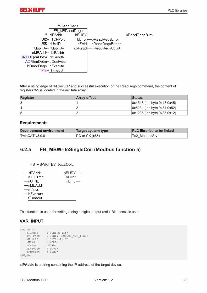
After a rising edge of "bExecute" and successful execution of the ReadRegs command, the content ofregisters 3-5 is located in the arrData array:
Register Array offset Status3 1 0x4543 ( as byte 0x43 0x45)4 2 0x5234 ( as byte 0x34 0x52)5 2 0x1235 ( as byte 0x35 0x12)
Requirements
Development environment Target system type PLC libraries to be linkedTwinCAT v3.0.0 PC or CX (x86) Tc2_ModbusSrv
6.2.5 FB_MBWriteSingleCoil (Modbus function 5)
This function is used for writing a single digital output (coil). Bit access is used.
VAR_INPUT
VAR_INPUT sIPAddr : STRING(15); nTCPPort : UINT:= MODBUS_TCP_PORT; nUnitID : BYTE:=16#FF; nMBAddr : WORD; nValue : WORD; bExecute : BOOL; tTimeout : TIME;END_VAR
sIPAddr: Is a string containing the IP address of the target device.
TC3 Modbus TCP 29Version: 1.2
PLC libraries
nTCPPort: Port number of the target device.
nUnitID: Identification number of a serial sub-network device. If a device is addressed directly via TCP/IP,this value must be 16#FF.
nMBAddr: Address of the digital output (bit offset).
nValue: Value to be written into the digital output. The value 16#FF00 switches the output on, 16#0000switches it off.
bExecute: The function block is activated by a rising edge at this input.
tTimeout: States the length of the timeout that may not be exceeded by execution of the ADS command.
VAR_OUTPUT
VAR_OUTPUT bBUSY : BOOL; bError : BOOL; nErrId : UDINT;END_VAR
bBusy : When the function block is activated this output is set. It remains set until an acknowledgement isreceived.
bError : If an ADS error should occur during the transfer of the command, then this output is set once thebBusy output is reset.
nErrId : Supplies the ADS error number [} 57] when the bError output is set.
Function specific ADS error code Possible reason0x8001 Modbus function not implemented0x8002 Invalid address or length0x8003 Invalid parameters: - wrong number of registers0x8004 Modbus server error
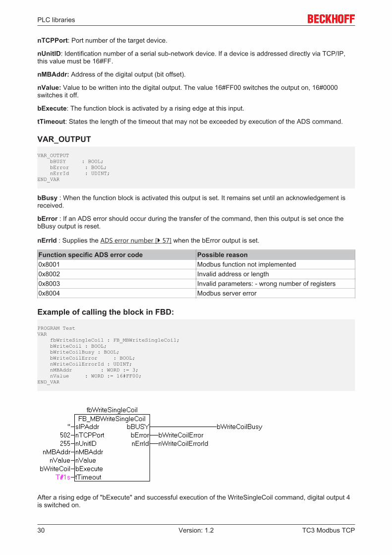
Example of calling the block in FBD:
PROGRAM TestVAR fbWriteSingleCoil : FB_MBWriteSingleCoil; bWriteCoil : BOOL; bWriteCoilBusy : BOOL; bWriteCoilError : BOOL; nWriteCoilErrorId : UDINT; nMBAddr : WORD := 3; nValue : WORD := 16#FF00;END_VAR
After a rising edge of "bExecute" and successful execution of the WriteSingleCoil command, digital output 4is switched on.
TC3 Modbus TCP30 Version: 1.2

PLC libraries
Requirements
Development environment Target system type PLC libraries to be linkedTwinCAT v3.0.0 PC or CX (x86) Tc2_ModbusSrv
6.2.6 FB_MBWriteSingleReg (Modbus function 6)
This function is used for writing an individual output register. 16 bit access is used.
VAR_INPUT
VAR_INPUT sIPAddr : STRING(15); nTCPPort : UINT:= MODBUS_TCP_PORT; nUnitID : BYTE:=16#FF; nMBAddr : WORD; nValue : WORD; bExecute : BOOL; tTimeout : TIME;END_VAR
sIPAddr: Is a string containing the IP address of the target device.
nTCPPort: Port number of the target device.
nUnitID: Identification number of a serial sub-network device. If a device is addressed directly via TCP/IP,this value must be 16#FF.
nMBAddr: Address of the output register (word offset).
nValue: Value to be written into the register (word value).
bExecute: The function block is activated by a rising edge at this input.
tTimeout: States the length of the timeout that may not be exceeded by execution of the ADS command.
VAR_OUTPUT
VAR_OUTPUT bBUSY : BOOL; bError : BOOL; nErrId : UDINT;END_VAR
bBusy : When the function block is activated this output is set. It remains set until an acknowledgement isreceived.
bError : If an ADS error should occur during the transfer of the command, then this output is set once thebBusy output is reset.
nErrId : Supplies the ADS error number [} 57] when the bError output is set.
TC3 Modbus TCP 31Version: 1.2

PLC libraries
Function specific ADS error code Possible reason0x8001 Modbus function not implemented0x8002 Invalid address or length0x8003 Invalid parameters: - wrong number of registers0x8004 Modbus server error
Example of calling the block in FBD:
PROGRAM TestVAR fbWriteSingleReg: FB_MBWriteSingleReg; bWriteReg : BOOL; bWriteRegBusy : BOOL; bWriteRegError : BOOL; nWriteRegErrorId: UDINT; nMBAddr : WORD := 4; nValue : WORD := 16#1234; END_VAR
After a rising edge of "bExecute" and successful execution of the WriteSingleReg command, the value16#1234 is written into register 5.
Requirements
Development environment Target system type PLC libraries to be linkedTwinCAT v3.0.0 PC or CX (x86) Tc2_ModbusSrv
6.2.7 FB_MBWriteCoils (Modbus function 15)
TC3 Modbus TCP32 Version: 1.2

PLC libraries
This function is used for writing 1 to 2048 digital outputs (coils). One digital output corresponds to one bit ofthe write data bytes.
VAR_INPUT
VAR_INPUT sIPAddr : STRING(15); nTCPPort : UINT:= MODBUS_TCP_PORT; nUnitID : BYTE:=16#FF; nQuantity : WORD; nMBAddr : WORD; cbLength : UDINT; pSrcAddr : POINTER OF BYTE; bExecute : BOOL; tTimeout : TIME;END_VAR
sIPAddr: Is a string containing the IP address of the target device.
nTCPPort: Port number of the target device.
nUnitID: Identification number of a serial sub-network device. If a device is addressed directly via TCP/IP,this value must be 16#FF.
nQuantity: Number of digital outputs to be written (data bits). nQuantity must be > 0.
nMBAddr: Start address of the digital outputs to be written (bit offset).
cbLength: Contains the max. byte size of the source buffer containing the data to be written. The minimumbuffer byte size must be: (nQuantity + 7) / 8.
pSrcAddr: Contains the address of the source buffer containing the data to be written. The buffer can be asingle variable, an array or a structure, whose address can be found with the ADR operator.
bExecute: The function block is activated by a rising edge at this input.
tTimeout: States the length of the timeout that may not be exceeded by execution of the ADS command.
VAR_OUTPUT
VAR_OUTPUT bBUSY : BOOL; bError : BOOL; nErrId : UDINT; cbRead : UDINT;END_VAR
bBusy : When the function block is activated this output is set. It remains set until an acknowledgement isreceived.
bError : If an ADS error should occur during the transfer of the command, then this output is set once thebBusy output is reset.
nErrId : Supplies the ADS error number [} 57] when the bError output is set.
Function specific ADS error code Possible reason0x8001 Modbus function not implemented0x8002 Invalid address or length0x8003 Invalid parameters: - wrong number of registers0x8004 Modbus server error
Example of calling the block in FBD:
PROGRAM TestVAR fbWriteCoils : FB_MBWriteCoils;
TC3 Modbus TCP 33Version: 1.2

PLC libraries
bWriteCoils : BOOL; bWriteCoilsBusy : BOOL; bWriteCoilsError : BOOL; nWriteCoilsErrorId: UDINT; nWriteCoilsCount : UDINT; nQuantity : WORD := 10; nMBAddr : WORD := 14; arrData : ARRAY [1..2] OF BYTE := 16#75,16#03;END_VAR
After a rising edge of "bExecute" and successful execution of the ReadCoils command, the content of thearrData array is written to digital outputs 15 - 24:
Bit 0 1 1 1 0 1 0 1 0 0 0 0 0 0 1 1Output
22 21 20 19 18 17 16 15 X X X X X X 24 23
Requirements
Development environment Target system type PLC libraries to be linkedTwinCAT v3.0.0 PC or CX (x86) Tc2_ModbusSrv
6.2.8 FB_MBWriteRegs (Modbus function 16)
This function is used for writing 1 to 128 output registers (16 bit).
VAR_INPUT
VAR_INPUT sIPAddr : STRING(15); nTCPPort : UINT:= MODBUS_TCP_PORT;
TC3 Modbus TCP34 Version: 1.2

PLC libraries
nUnitID : BYTE:=16#FF; nQuantity : WORD; nMBAddr : WORD; cbLength : UDINT; pSrcAddr : POINTER OF BYTE; bExecute : BOOL; tTimeout : TIME;END_VAR
sIPAddr: Is a string containing the IP address of the target device.
nTCPPort: Port number of the target device.
nUnitID: Identification number of a serial sub-network device. If a device is addressed directly via TCP/IP,this value must be 16#FF.
nQuantity: Number of output registers (data words) to be written.
nMBAddr: Start address of the output registers to be written (word offset).
cbLength: Contains the max. byte size of the source buffer. The minimum buffer byte size must be:nQuantity * 2.
pSrcAddr: Contains the address of the source buffer containing the data to be written. The buffer can be asingle variable, an array or a structure, whose address can be found with the ADR operator.
bExecute The function block is activated by a rising edge at this input.
tTimeout: States the length of the timeout that may not be exceeded by execution of the ADS command.
VAR_OUTPUT
VAR_OUTPUT bBUSY : BOOL; bError : BOOL; nErrId : UDINT;END_VAR
bBusy: When the function block is activated this output is set. It remains set until an acknowledgement isreceived.
bError: If an ADS error should occur during the transfer of the command, then this output is set once thebBusy output is reset.
nErrId: Supplies the ADS error number [} 57] when the bError output is set.
Function specific ADS error code Possible reason0x8001 Modbus function not implemented0x8002 Invalid address or length0x8003 Invalid parameters: - wrong number of registers0x8004 Modbus server error
Example of calling the block in FBD:
PROGRAM TestVAR fbWriteRegs : FB_MBWriteRegs; bWriteRegs : BOOL; bWriteRegsBusy : BOOL; bWriteRegsError : BOOL; nWriteRegsErrorId : UDINT; nWriteRegsCount : UDINT; nQuantity : WORD := 3; nMBAddr : WORD := 4; arrData : ARRAY [1..3] OF WORD;END_VAR
TC3 Modbus TCP 35Version: 1.2

PLC libraries
After a rising edge of "bExecute" and successful execution of the ReadRegs command, the content of thearrData array is written to registers 5-7.
Requirements
Development environment Target system type PLC libraries to be linkedTwinCAT v3.0.0 PC or CX (x86) Tc2_ModbusSrv
6.2.9 FB_MBReadWriteRegs (Modbus-Funktion 23)
This function first reads 1 to 128 output registers (16 bit) and then writes 1 to 128 output registers (16 bit).
VAR_INPUT
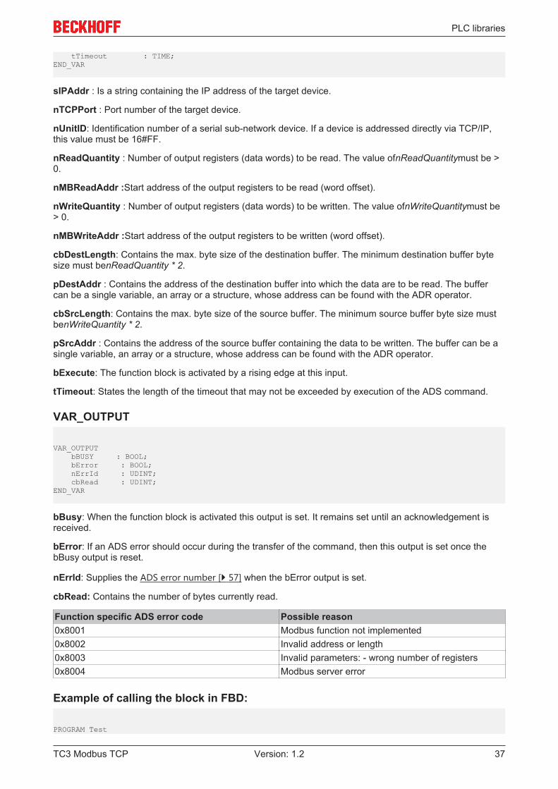
VAR_INPUT sIPAddr : STRING(15); nTCPPort : UINT:= MODBUS_TCP_PORT; nUnitID : BYTE:=16#FF; nReadQuantity : WORD; nMBReadAddr : WORD; nWriteQuantity : WORD; nMBWriteAddr : WORD; cbDestLength : UDINT; pDestAddr : POINTER OF BYTE; cbSrcLength : UDINT; pSrcAddr : POINTER OF BYTE; bExecute : BOOL;
TC3 Modbus TCP36 Version: 1.2
PLC libraries
tTimeout : TIME;END_VAR
sIPAddr : Is a string containing the IP address of the target device.
nTCPPort : Port number of the target device.
nUnitID: Identification number of a serial sub-network device. If a device is addressed directly via TCP/IP,this value must be 16#FF.
nReadQuantity : Number of output registers (data words) to be read. The value ofnReadQuantitymust be >0.
nMBReadAddr :Start address of the output registers to be read (word offset).
nWriteQuantity : Number of output registers (data words) to be written. The value ofnWriteQuantitymust be> 0.
nMBWriteAddr :Start address of the output registers to be written (word offset).
cbDestLength: Contains the max. byte size of the destination buffer. The minimum destination buffer bytesize must benReadQuantity * 2.
pDestAddr : Contains the address of the destination buffer into which the data are to be read. The buffercan be a single variable, an array or a structure, whose address can be found with the ADR operator.
cbSrcLength: Contains the max. byte size of the source buffer. The minimum source buffer byte size mustbenWriteQuantity * 2.
pSrcAddr : Contains the address of the source buffer containing the data to be written. The buffer can be asingle variable, an array or a structure, whose address can be found with the ADR operator.
bExecute: The function block is activated by a rising edge at this input.
tTimeout: States the length of the timeout that may not be exceeded by execution of the ADS command.
VAR_OUTPUT
VAR_OUTPUT bBUSY : BOOL; bError : BOOL; nErrId : UDINT; cbRead : UDINT;END_VAR
bBusy: When the function block is activated this output is set. It remains set until an acknowledgement isreceived.
bError: If an ADS error should occur during the transfer of the command, then this output is set once thebBusy output is reset.
nErrId: Supplies the ADS error number [} 57] when the bError output is set.
cbRead: Contains the number of bytes currently read.
Function specific ADS error code Possible reason0x8001 Modbus function not implemented0x8002 Invalid address or length0x8003 Invalid parameters: - wrong number of registers0x8004 Modbus server error
Example of calling the block in FBD:
PROGRAM Test
TC3 Modbus TCP 37Version: 1.2

PLC libraries
VAR fbReadWriteRegs : FB_MBReadWriteRegs; bReadWriteRegs : BOOL; bReadWriteRegsBusy : BOOL; bReadWriteRegsError : BOOL; nReadWriteRegsErrorId : UDINT; nReadWriteRegsCount : UDINT; nRdQuantity : WORD; nRdMBAddr : WORD; nWrQuantity : WORD; nWrMBAddr : WORD; arrRdData : ARRAY [1..9] OF WORD; arrWrData : ARRAY [1..9] OF WORD;END_VAR
After a rising edge of "bExecute" and successful execution of the ReadWriteRegs command, arrRdDatacontains the read register data, and the data from arrWrData are written to the registers.
Requirements
Development environment Target system type PLC libraries to be linkedTwinCAT v3.0.0 PC or CX (x86) Tc2_ModbusSrv
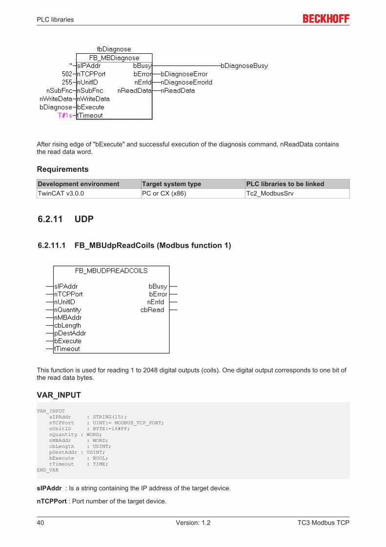
6.2.10 FB_MBDiagnose (Modbus function 8)
The diagnosis function provides a series of tests for checking the communication system between themaster and the slave and for examining a variety of internal error states within the slave.
TC3 Modbus TCP38 Version: 1.2

PLC libraries
VAR_INPUT
VAR_INPUT sIPAddr : STRING(15); nTCPPort : UINT:= MODBUS_TCP_PORT; nUnitID : BYTE:=16#FF; nSubFnc : WORD; nWriteData : WORD; bExecute : BOOL; tTimeout : TIME;END_VAR
sIPAddr : Is a string containing the IP address of the target device.
nTCPPort : Port number of the target device.
nUnitID: Identification number of a serial sub-network device. If a device is addressed directly via TCP/IP,this value must be 16#FF.
nSubFnc : The sub-function to be executed.
nWriteData: The data word to be written.
bExecute: The function block is activated by a rising edge at this input.
tTimeout: States the length of the timeout that may not be exceeded by execution of the ADS command.
VAR_OUTPUT
VAR_OUTPUT bBusy : BOOL; bError : BOOL; nErrId : UDINT; nReadData : WORD;END_VAR
bBusy : When the function block is activated this output is set. It remains set until an acknowledgement isreceived.
bError : If an ADS error should occur during the transfer of the command, then this output is set once thebBusy output is reset.
nErrId : Supplies the ADS error number [} 57] when the bError output is set.
nReadData: Supplies the read data word.
Function specific ADS error code Possible reason0x8001 Modbus function not implemented0x8002 Invalid address or length0x8003 Invalid parameters: - wrong number of registers0x8004 Modbus server error
Example of calling the block in FBD:
PROGRAM TestVAR fbDiagnose : FB_MBDiagnose; bDiagnose : BOOL; bDiagnoseBusy : BOOL; bDiagnoseError : BOOL; nDiagnoseErrorId: UDINT; nSubFnc : WORD; nReadData : WORD; nWriteData : WORD;END_VAR
TC3 Modbus TCP 39Version: 1.2
PLC libraries
After rising edge of "bExecute" and successful execution of the diagnosis command, nReadData containsthe read data word.
Requirements
Development environment Target system type PLC libraries to be linkedTwinCAT v3.0.0 PC or CX (x86) Tc2_ModbusSrv
6.2.11 UDP
6.2.11.1 FB_MBUdpReadCoils (Modbus function 1)
This function is used for reading 1 to 2048 digital outputs (coils). One digital output corresponds to one bit ofthe read data bytes.
VAR_INPUT
VAR_INPUT sIPAddr : STRING(15); nTCPPort : UINT:= MODBUS_TCP_PORT; nUnitID : BYTE:=16#FF; nQuantity : WORD; nMBAddr : WORD; cbLength : UDINT; pDestAddr : UDINT; bExecute : BOOL; tTimeout : TIME;END_VAR
sIPAddr : Is a string containing the IP address of the target device.
nTCPPort : Port number of the target device.
TC3 Modbus TCP40 Version: 1.2

PLC libraries
nUnitID: Identification number of a serial sub-network device. If a device is addressed directly via TCP/IP,this value must be 16#FF.
nQuantity : Number of digital inputs (data bits) to be read. The value of nQuantity must be > 0.
nMBAddr : Start address of the digital inputs to be read (bit offset).
cbLength : Contains the max. byte size of the destination buffer into which the data are to be read. Theminimum buffer byte size must be: (nQuantity + 7) / 8.
pDestAddr : Contains the address of the destination buffer into which the data are to be read. The buffercan be a single variable, an array or a structure, whose address can be found with the ADR operator.
bExecute: The function block is activated by a rising edge at this input.
tTimeout: States the length of the timeout that may not be exceeded by execution of the ADS command.
VAR_OUTPUT
VAR_OUTPUT bBUSY : BOOL; bError : BOOL; nErrId : UDINT; cbRead : UDINT;END_VAR
bBusy : When the function block is activated this output is set. It remains set until an acknowledgement isreceived.
bError : If an ADS error should occur during the transfer of the command, then this output is set once thebBusy output is reset.
nErrId : Supplies the ADS error number [} 57] when the bError output is set.
cbRead: Contains the number of bytes currently read.
Function specific ADS error code Possible reason0x8001 Modbus function not implemented0x8002 Invalid address or length0x8003 Invalid parameters: - wrong number of registers0x8004 Modbus server error
Requirements
Development environment Target system type PLC libraries to be linkedTwinCAT v3.0.0 PC or CX (x86) Tc2_ModbusSrv
TC3 Modbus TCP 41Version: 1.2
PLC libraries
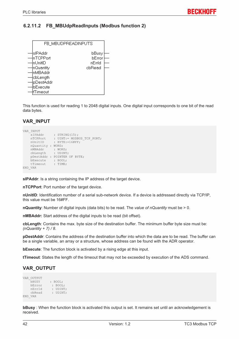
6.2.11.2 FB_MBUdpReadInputs (Modbus function 2)
This function is used for reading 1 to 2048 digital inputs. One digital input corresponds to one bit of the readdata bytes.
VAR_INPUT
VAR_INPUT sIPAddr : STRING(15); nTCPPort : UINT:= MODBUS_TCP_PORT; nUnitID : BYTE:=16#FF; nQuantity : WORD; nMBAddr : WORD; cbLength : UDINT; pDestAddr : POINTER OF BYTE; bExecute : BOOL; tTimeout : TIME;END_VAR
sIPAddr: Is a string containing the IP address of the target device.
nTCPPort: Port number of the target device.
nUnitID: Identification number of a serial sub-network device. If a device is addressed directly via TCP/IP,this value must be 16#FF.
nQuantity: Number of digital inputs (data bits) to be read. The value of nQuantity must be > 0.
nMBAddr: Start address of the digital inputs to be read (bit offset).
cbLength: Contains the max. byte size of the destination buffer. The minimum buffer byte size must be:(nQuantity + 7) / 8.
pDestAddr: Contains the address of the destination buffer into which the data are to be read. The buffer canbe a single variable, an array or a structure, whose address can be found with the ADR operator.
bExecute: The function block is activated by a rising edge at this input.
tTimeout: States the length of the timeout that may not be exceeded by execution of the ADS command.
VAR_OUTPUT
VAR_OUTPUT bBUSY : BOOL; bError : BOOL; nErrId : UDINT; cbRead : UDINT;END_VAR
bBusy : When the function block is activated this output is set. It remains set until an acknowledgement isreceived.
TC3 Modbus TCP42 Version: 1.2

PLC libraries
bError : If an ADS error should occur during the transfer of the command, then this output is set once thebBusy output is reset.
nErrId : Supplies the ADS error number [} 57] when the bError output is set.
cbRead: Contains the number of bytes currently read.
Function specific ADS error code Possible reason0x8001 Modbus function not implemented0x8002 Invalid address or length0x8003 Invalid parameters: - wrong number of registers0x8004 Modbus server error
Requirements
Development environment Target system type PLC libraries to be linkedTwinCAT v3.0.0 PC or CX (x86) Tc2_ModbusSrv
6.2.11.3 FB_MBUdpReadRegs (Modbus function 3)
This function is used for reading 1 to 128 output registers (16 bit). The first byte contains the lower eight bitsand the second byte the upper eight bits.
VAR_INPUT
VAR_INPUT sIPAddr : STRING(15); nTCPPort : UINT:= MODBUS_TCP_PORT; nUnitID : BYTE:=16#FF; nQuantity : WORD; nMBAddr : WORD; cbLength : UDINT; pDestAddr : POINTER OF BYTE; bExecute : BOOL; tTimeout : TIME;END_VAR
sIPAddr: Is a string containing the IP address of the target device.
nTCPPort: Port number of the target device.
nUnitID: Identification number of a serial sub-network device. If a device is addressed directly via TCP/IP,this value must be 16#FF.
nQuantity: Number of output registers (data words) to be read. The value of nQuantity must be > 0.
nMBAddr: Start address of the output registers to be read (word offset).
TC3 Modbus TCP 43Version: 1.2

PLC libraries
cbLength: Contains the max. byte size of the destination buffer. The minimum buffer byte size must be:nQuantity * 2.
pDestAddr: Contains the address of the destination buffer into which the data are to be read. The buffer canbe a single variable, an array or a structure, whose address can be found with the ADR operator.
bExecute: The function block is activated by a rising edge at this input.
tTimeout: States the length of the timeout that may not be exceeded by execution of the ADS command.
VAR_OUTPUT
VAR_OUTPUT bBUSY : BOOL; bError : BOOL; nErrId : UDINT; cbRead : UDINT;END_VAR
bBusy : When the function block is activated this output is set. It remains set until an acknowledgement isreceived.
bError : If an ADS error should occur during the transfer of the command, then this output is set once thebBusy output is reset.
nErrId : Supplies the ADS error number [} 57] when the bError output is set.
cbRead: Contains the number of bytes currently read.
Function specific ADS error code Possible reason0x8001 Modbus function not implemented0x8002 Invalid address or length0x8003 Invalid parameters: - wrong number of registers0x8004 Modbus server error
Requirements
Development environment Target system type PLC libraries to be linkedTwinCAT v3.0.0 PC or CX (x86) Tc2_ModbusSrv
6.2.11.4 FB_MBUdpReadInputRegs (Modbus function 4)
This function is used for reading 1 to 128 input registers (16 bit). Endian
TC3 Modbus TCP44 Version: 1.2

PLC libraries
VAR_INPUT
VAR_INPUT sIPAddr : STRING(15); nTCPPort : UINT:= MODBUS_TCP_PORT; nUnitID : BYTE:=16#FF; nQuantity : WORD; nMBAddr : WORD; cbLength : UDINT; pDestAddr : POINTER OF BYTE; bExecute : BOOL; tTimeout : TIME;END_VAR
sIPAddr: Is a string containing the IP address of the target device.
nTCPPort: Port number of the target device.
nUnitID: Identification number of a serial sub-network device. If a device is addressed directly via TCP/IP,this value must be 16#FF.
nQuantity: Number of input registers (data words) to be read. The value of nQuantity must be > 0.
nMBAddr: Start address of the input register to be read (word offset).
cbLength: Contains the max. byte size of the destination buffer. The minimum buffer byte size must be:nQuantity * 2.
pDestAddr: Contains the address of the destination buffer into which the data are to be read. The buffer canbe a single variable, an array or a structure, whose address can be found with the ADR operator.
bExecute: The function block is activated by a rising edge at this input.
tTimeout: States the length of the timeout that may not be exceeded by execution of the ADS command.
VAR_OUTPUT
VAR_OUTPUT bBUSY : BOOL; bError : BOOL; nErrId : UDINT; cbRead : UDINT;END_VAR
bBusy : When the function block is activated this output is set. It remains set until an acknowledgement isreceived.
bError : If an ADS error should occur during the transfer of the command, then this output is set once thebBusy output is reset.
nErrId : Supplies the ADS error number [} 57] when the bError output is set.
cbRead: Contains the number of bytes currently read.
Function specific ADS error code Possible reason0x8001 Modbus function not implemented0x8002 Invalid address or length0x8003 Invalid parameters: - wrong number of registers0x8004 Modbus server error
Requirements
Development environment Target system type PLC libraries to be linkedTwinCAT v3.0.0 PC or CX (x86) Tc2_ModbusSrv
TC3 Modbus TCP 45Version: 1.2

PLC libraries
6.2.11.5 FB_MBUdpWriteSingleCoil (Modbus function 5)
This function is used for writing a single digital output (coil). Bit access is used.
VAR_INPUT
VAR_INPUT sIPAddr : STRING(15); nTCPPort : UINT:= MODBUS_TCP_PORT; nUnitID : BYTE:=16#FF; nMBAddr : WORD; nValue : WORD; bExecute : BOOL; tTimeout : TIME;END_VAR
sIPAddr: Is a string containing the IP address of the target device.
nTCPPort: Port number of the target device.
nUnitID: Identification number of a serial sub-network device. If a device is addressed directly via TCP/IP,this value must be 16#FF.
nMBAddr: Address of the digital output (bit offset).
nValue: Value to be written into the digital output. The value 16#FF00 switches the output on, 16#0000switches it off.
bExecute: The function block is activated by a rising edge at this input.
tTimeout: States the length of the timeout that may not be exceeded by execution of the ADS command.
VAR_OUTPUT
VAR_OUTPUT bBUSY : BOOL; bError : BOOL; nErrId : UDINT;END_VAR
bBusy : When the function block is activated this output is set. It remains set until an acknowledgement isreceived.
bError : If an ADS error should occur during the transfer of the command, then this output is set once thebBusy output is reset.
nErrId : Supplies the ADS error number [} 57] when the bError output is set.
TC3 Modbus TCP46 Version: 1.2

PLC libraries
Function specific ADS error code Possible reason0x8001 Modbus function not implemented0x8002 Invalid address or length0x8003 Invalid parameters: - wrong number of registers0x8004 Modbus server error
Requirements
Development environment Target system type PLC libraries to be linkedTwinCAT v3.0.0 PC or CX (x86) Tc2_ModbusSrv
6.2.11.6 FB_MBUdpWriteSingleReg (Modbus function 6)
This function is used for writing an individual output register. 16 bit access is used.
VAR_INPUT
VAR_INPUT sIPAddr : STRING(15); nTCPPort : UINT:= MODBUS_TCP_PORT; nUnitID : BYTE:=16#FF; nMBAddr : WORD; nValue : WORD; bExecute : BOOL; tTimeout : TIME;END_VAR
sIPAddr: Is a string containing the IP address of the target device.
nTCPPort: Port number of the target device.
nUnitID: Identification number of a serial sub-network device. If a device is addressed directly via TCP/IP,this value must be 16#FF.
nMBAddr: Address of the output register (word offset).
nValue: Value to be written into the register (word value).
bExecute: The function block is activated by a rising edge at this input.
tTimeout: States the length of the timeout that may not be exceeded by execution of the ADS command.
VAR_OUTPUT
VAR_OUTPUT bBUSY : BOOL; bError : BOOL; nErrId : UDINT;END_VAR
TC3 Modbus TCP 47Version: 1.2
PLC libraries
bBusy : When the function block is activated this output is set. It remains set until an acknowledgement isreceived.
bError : If an ADS error should occur during the transfer of the command, then this output is set once thebBusy output is reset.
nErrId : Supplies the ADS error number [} 57] when the bError output is set.
Function specific ADS error code Possible reason0x8001 Modbus function not implemented0x8002 Invalid address or length0x8003 Invalid parameters: - wrong number of registers0x8004 Modbus server error
Requirements
Development environment Target system type PLC libraries to be linkedTwinCAT v3.0.0 PC or CX (x86) Tc2_ModbusSrv
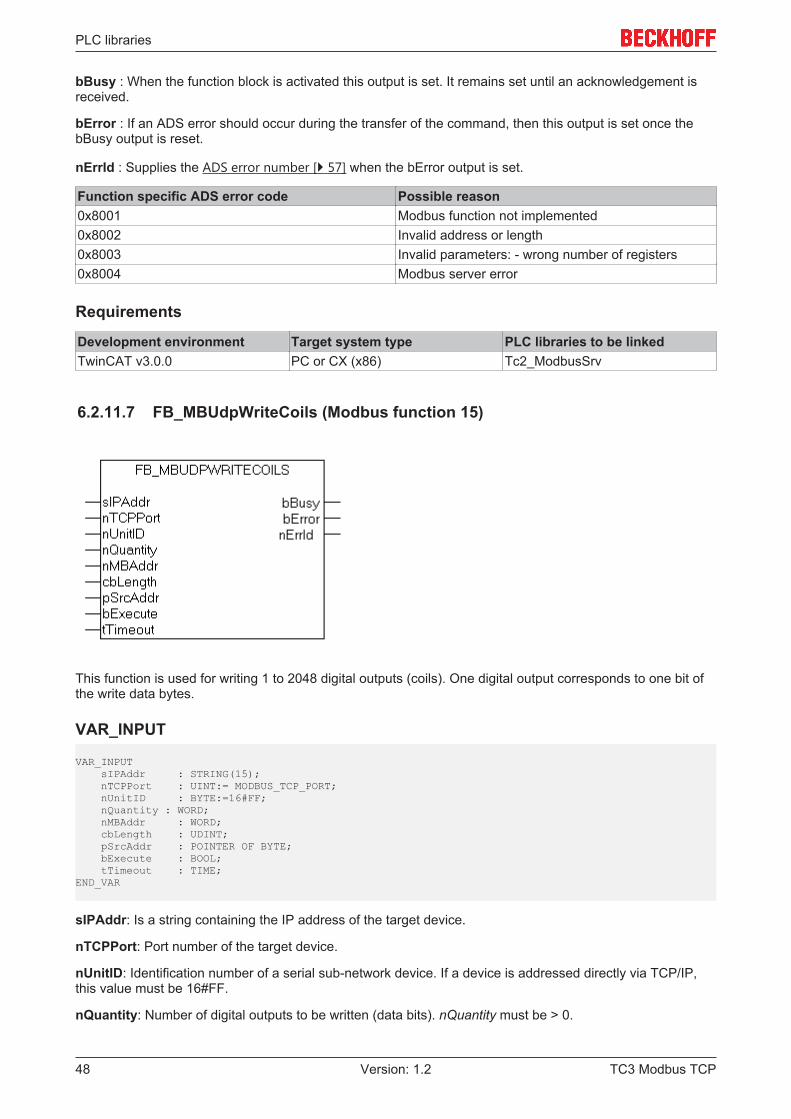
6.2.11.7 FB_MBUdpWriteCoils (Modbus function 15)
This function is used for writing 1 to 2048 digital outputs (coils). One digital output corresponds to one bit ofthe write data bytes.
VAR_INPUT
VAR_INPUT sIPAddr : STRING(15); nTCPPort : UINT:= MODBUS_TCP_PORT; nUnitID : BYTE:=16#FF; nQuantity : WORD; nMBAddr : WORD; cbLength : UDINT; pSrcAddr : POINTER OF BYTE; bExecute : BOOL; tTimeout : TIME;END_VAR
sIPAddr: Is a string containing the IP address of the target device.
nTCPPort: Port number of the target device.
nUnitID: Identification number of a serial sub-network device. If a device is addressed directly via TCP/IP,this value must be 16#FF.
nQuantity: Number of digital outputs to be written (data bits). nQuantity must be > 0.
TC3 Modbus TCP48 Version: 1.2

PLC libraries
nMBAddr: Start address of the digital outputs to be written (bit offset).
cbLength: Contains the max. byte size of the source buffer containing the data to be written. The minimumbuffer byte size must be: (nQuantity + 7) / 8.
pSrcAddr: Contains the address of the source buffer containing the data to be written. The buffer can be asingle variable, an array or a structure, whose address can be found with the ADR operator.
bExecute: The function block is activated by a rising edge at this input.
tTimeout: States the length of the timeout that may not be exceeded by execution of the ADS command.
VAR_OUTPUT
VAR_OUTPUT bBUSY : BOOL; bError : BOOL; nErrId : UDINT; cbRead : UDINT;END_VAR
bBusy : When the function block is activated this output is set. It remains set until an acknowledgement isreceived.
bError : If an ADS error should occur during the transfer of the command, then this output is set once thebBusy output is reset.
nErrId : Supplies the ADS error number [} 57] when the bError output is set.
Function specific ADS error code Possible reason0x8001 Modbus function not implemented0x8002 Invalid address or length0x8003 Invalid parameters: - wrong number of registers0x8004 Modbus server error
Requirements
Development environment Target system type PLC libraries to be linkedTwinCAT v3.0.0 PC or CX (x86) Tc2_ModbusSrv
6.2.11.8 FB_MBUdpWriteRegs (Modbus function 16)
This function is used for writing 1 to 128 output registers (16 bit).
TC3 Modbus TCP 49Version: 1.2

PLC libraries
VAR_INPUT
VAR_INPUT sIPAddr : STRING(15); nTCPPort : UINT:= MODBUS_TCP_PORT; nUnitID : BYTE:=16#FF; nQuantity : WORD; nMBAddr : WORD; cbLength : UDINT; pSrcAddr : POINTER OF BYTE; bExecute : BOOL; tTimeout : TIME;END_VAR
sIPAddr: Is a string containing the IP address of the target device.
nTCPPort: Port number of the target device.
nUnitID: Identification number of a serial sub-network device. If a device is addressed directly via TCP/IP,this value must be 16#FF.
nQuantity: Number of output registers (data words) to be written.
nMBAddr: Start address of the output registers to be written (word offset).
cbLength: Contains the max. byte size of the source buffer. The minimum buffer byte size must be:nQuantity * 2.
pSrcAddr: Contains the address of the source buffer containing the data to be written. The buffer can be asingle variable, an array or a structure, whose address can be found with the ADR operator.
bExecute The function block is activated by a rising edge at this input.
tTimeout: States the length of the timeout that may not be exceeded by execution of the ADS command.
VAR_OUTPUT
VAR_OUTPUT bBUSY : BOOL; bError : BOOL; nErrId : UDINT;END_VAR
bBusy: When the function block is activated this output is set. It remains set until an acknowledgement isreceived.
bError: If an ADS error should occur during the transfer of the command, then this output is set once thebBusy output is reset.
nErrId: Supplies the ADS error number [} 57] when the bError output is set.
Function specific ADS error code Possible reason0x8001 Modbus function not implemented0x8002 Invalid address or length0x8003 Invalid parameters: - wrong number of registers0x8004 Modbus server error
Requirements
Development environment Target system type PLC libraries to be linkedTwinCAT v3.0.0 PC or CX (x86) Tc2_ModbusSrv
TC3 Modbus TCP50 Version: 1.2

PLC libraries
6.2.11.9 FB_MBUdpReadWriteRegs (Modbus function 23)
This function first reads 1 to 128 output registers (16 bit) and then writes 1 to 128 output registers (16 bit).
VAR_INPUT
VAR_INPUT sIPAddr : STRING(15); nTCPPort : UINT:= MODBUS_TCP_PORT; nUnitID : BYTE:=16#FF; nReadQuantity : WORD; nMBReadAddr : WORD; nWriteQuantity : WORD; nMBWriteAddr : WORD; cbDestLength : UDINT; pDestAddr : POINTER OF BYTE; cbSrcLength : UDINT; pSrcAddr : POINTER OF BYTE; bExecute : BOOL; tTimeout : TIME;END_VAR
sIPAddr : Is a string containing the IP address of the target device.
nTCPPort : Port number of the target device.
nUnitID: Identification number of a serial sub-network device. If a device is addressed directly via TCP/IP,this value must be 16#FF.
nReadQuantity : Number of output registers (data words) to be read. The value of nReadQuantity must be >0.
nMBReadAddr : Start address of the output registers to be read (word offset).
nWriteQuantity : Number of output registers (data words) to be written. The value of nWriteQuantity must be> 0.
nMBWriteAddr : Start address of the output registers to be written (word offset).
cbDestLength : Contains the max. byte size of the destination buffer. The minimum destination buffer bytesize must be nReadQuantity * 2.
pDestAddr : Contains the address of the destination buffer into which the data are to be read. The buffercan be a single variable, an array or a structure, whose address can be found with the ADR operator.
cbSrcLength : Contains the max. byte size of the source buffer. The minimum source buffer byte size mustbe nWriteQuantity * 2.
TC3 Modbus TCP 51Version: 1.2

PLC libraries
pSrcAddr : Contains the address of the source buffer containing the data to be written. The buffer can be asingle variable, an array or a structure, whose address can be found with the ADR operator.
bExecute: The function block is activated by a rising edge at this input.
tTimeout: States the length of the timeout that may not be exceeded by execution of the ADS command.
VAR_OUTPUT
VAR_OUTPUT bBUSY : BOOL; bError : BOOL; nErrId : UDINT; cbRead : UDINT;END_VAR
bBusy : When the function block is activated this output is set. It remains set until an acknowledgement isreceived.
bError : If an ADS error should occur during the transfer of the command, then this output is set once thebBusy output is reset.
nErrId : Supplies the ADS error number [} 57] when the bError output is set.
cbRead: Contains the number of bytes currently read.
Function specific ADS error code Possible reason0x8001 Modbus function not implemented0x8002 Invalid address or length0x8003 Invalid parameters: - wrong number of registers0x8004 Modbus server error
Requirements
Development environment Target system type PLC libraries to be linkedTwinCAT v3.0.0 PC or CX (x86) Tc2_ModbusSrv
6.2.11.10 FB_MBUdpDiagnose (Modbus function 8)
The diagnosis function provides a series of tests for checking the communication system between themaster and the slave and for examining a variety of internal error states within the slave.
VAR_INPUT
VAR_INPUT sIPAddr : STRING(15); nTCPPort : UINT:= MODBUS_TCP_PORT; nUnitID : BYTE:=16#FF; nSubFnc : WORD;
TC3 Modbus TCP52 Version: 1.2

PLC libraries
nWriteData : WORD; bExecute : BOOL; tTimeout : TIME;END_VAR
sIPAddr : Is a string containing the IP address of the target device.
nTCPPort : Port number of the target device.
nUnitID: Identification number of a serial sub-network device. If a device is addressed directly via TCP/IP,this value must be 16#FF.
nSubFnc : The sub-function to be executed.
nWriteData: The data word to be written.
bExecute: The function block is activated by a rising edge at this input.
tTimeout: States the length of the timeout that may not be exceeded by execution of the ADS command.
VAR_OUTPUT
VAR_OUTPUT bBusy : BOOL; bError : BOOL; nErrId : UDINT; nReadData : WORD;END_VAR
bBusy : When the function block is activated this output is set. It remains set until an acknowledgement isreceived.
bError : If an ADS error should occur during the transfer of the command, then this output is set once thebBusy output is reset.
nErrId : Supplies the ADS error number [} 57] when the bError output is set.
nReadData: Supplies the read data word.
Function specific ADS error code Possible reason0x8001 Modbus function not implemented0x8002 Invalid address or length0x8003 Invalid parameters: - wrong number of registers0x8004 Modbus server error
Requirements
Development environment Target system type PLC libraries to be linkedTwinCAT v3.0.0 PC or CX (x86) Tc2_ModbusSrv
6.3 Global constants
6.3.1 Library VersionAll libraries have a specific version. This version is shown in the PLC library repository too.A global constant contains the library version information:
Global_Version
TC3 Modbus TCP 53Version: 1.2

PLC libraries
VAR_GLOBAL CONSTANT stLibVersion_Tc2_ModbusSrv : ST_LibVersion;END_VAR
To compare the existing version to a required version the function F_CmpLibVersion (defined in Tc2_Systemlibrary) is offered.
Hint: All other possibilities known from TwinCAT2 libraries to query a library version are obsolete!
TC3 Modbus TCP54 Version: 1.2

Samples
7 Samples
7.1 Sample: Digital IO accessThis sample explains the access to a TwinCAT system via Modbus.
The default mapping [} 18] of the TwinCAT Modbus TCP mapps the digital output (coils) to the physicaloutputs of the PLC.PROGRAM MAINVAR Q00 AT%QX0.0 : BOOL; Q01 AT%QX0.1 : BOOL; Q02 AT%QX0.2 : BOOL; Q03 AT%QX0.3 : BOOL; Q04 AT%QX0.4 : BOOL; Q05 AT%QX0.5 : BOOL; Q06 AT%QX0.6 : BOOL; Q07 AT%QX0.7 : BOOL;
fbWriteCoils : FB_MBWriteCoils; bWrite : BOOL; nValue : INT;END_VAR
IF NOT bWrite THEN nValue := nValue + 1;
bWrite := TRUE;
fbWriteCoils.nQuantity := 8; fbWriteCoils.cbLength := SIZEOF(nValue); fbWriteCoils.pSrcAddr := ADR(nValue); fbWriteCoils.tTimeout := T#5s; fbWriteCoils(bExecute:=TRUE);
ELSEIF NOT fbWriteCoils.bBUSY THEN bWrite :=FALSE; END_IF fbWriteCoils(bExecute:=FALSE);END_IF
The counter nValue will be written to physical outputs of the plc (Q00-Q07) by a rising edge of bWrite.
The bit ordering is explained in this table:
Bit 8 MSB 7 6 5 4 3 2 1 LSBOutput 7 6 5 4 3 2 1 0
MSB = Most significant bit
LSB = Least significant bit
Requirements
Development environment Target system type PLC libraries to be linkedTwinCAT v3.0.0 PC or CX (x86) Tc2_ModbusSrv
TC3 Modbus TCP 55Version: 1.2

Samples
7.2 Sample: Multiple register accessThis sample explains the access to the register of aTwinCAT system via Modbus.
The Modbusaddress 0x3000 is mapped by the default-configuration to the memory area of the plc (ADS-Indexgroup 0x4020)PROGRAM MAINVARipAddr : STRING(15) := '';M0 AT%MB0 : ARRAY [0..3] OF WORD;nValue : ARRAY [0..3] OF WORD;fbWriteRegs : FB_MBWriteRegs;bWriteRegs : BOOL;END_VAR
IF NOT bWriteRegs THENnValue[0]:= nValue[0]+1;nValue[1]:= nValue[1]+1;nValue[2]:= nValue[2]+1;nValue[3]:= nValue[3]+1;
bWriteRegs :=TRUE;
fbWriteRegs.sIPAddr :=ipAddr;fbWriteRegs.nQuantity := 4;fbWriteRegs.nMBAddr := 16#3000;fbWriteRegs.cbLength := SIZEOF(nValue);fbWriteRegs.pSrcAddr := ADR(nValue);fbWriteRegs.tTimeout := T#5s;fbWriteRegs(bExecute:=TRUE);ELSEIF NOT fbWriteRegs.bBUSY THENbWriteRegs :=FALSE;END_IFfbWriteRegs(bExecute:=FALSE);END_IF
The array arrValue will be written to the memory area of the plc (M0) by a rising edge on bWriteRegs.
Requirements
Development environment Target system type PLC libraries to be linkedTwinCAT v3.0.0 PC or CX (x86) Tc2_ModbusSrv
Also see about this2 Mapping between Modbus and ADS [} 18]
TC3 Modbus TCP56 Version: 1.2

Appendix
8 Appendix
8.1 Overview
TwinCAT ADS return code
Hex Dezimal Source0x00000000-0x00007800 0-30720 TwinCAT System return codes0x00008000-0x000080FF 32768-33023 Internal TwinCAT Modbus TCP0x80070000-0x8007FFFF 2147942400-2148007935 Returncode - 0x80070000 =Win32
System Returncode
TwinCAT Modbus TCP return code
Function specific ADS return code Possible reason0x8001 Modbus function not implemented0x8002 Invalid address or length0x8003 Invalid parameters: - wrong number of registers0x8004 Modbus server error
Requirements
Development environment Target system type PLC libraries to be linkedTwinCAT v3.0.0 PC or CX (x86) Tc2_ModbusSrv
8.2 ADS Return CodesError codes: 0x000 [} 58]..., 0x500 [} 58]..., 0x700 [} 59]..., 0x1000 [} 61]...
TC3 Modbus TCP 57Version: 1.2

Appendix
Global Error CodesHex Dec Description
0x0 0 no error0x1 1 Internal error0x2 2 No Rtime0x3 3 Allocation locked memory error0x4 4 Insert mailbox error0x5 5 Wrong receive HMSG0x6 6 target port not found0x7 7 target machine not found0x8 8 Unknown command ID0x9 9 Bad task ID0xA 10 No IO0xB 11 Unknown ADS command0xC 12 Win 32 error0xD 13 Port not connected0xE 14 Invalid ADS length0xF 15 Invalid ADS Net ID0x10 16 Low Installation level0x11 17 No debug available0x12 18 Port disabled0x13 19 Port already connected0x14 20 ADS Sync Win32 error0x15 21 ADS Sync Timeout0x16 22 ADS Sync AMS error0x17 23 ADS Sync no index map0x18 24 Invalid ADS port0x19 25 No memory0x1A 26 TCP send error0x1B 27 Host unreachable0x1C 28 Invalid AMS fragment
Router Error CodesHex Dec Name Description
0x500 1280 ROUTERERR_NOLOCKEDMEMORY No locked memory can be allocated0x501 1281 ROUTERERR_RESIZEMEMORY The size of the router memory could not be changed0x502 1282 ROUTERERR_MAILBOXFULL The mailbox has reached the maximum number of possible
messages. The current sent message was rejected0x503 1283 ROUTERERR_DEBUGBOXFULL The mailbox has reached the maximum number of possible
messages.The sent message will not be displayed in the debug monitor
0x504 1284 ROUTERERR_UNKNOWNPORTTYPE Unknown port type0x505 1285 ROUTERERR_NOTINITIALIZED Router is not initialized0x506 1286 ROUTERERR_PORTALREADYINUSE The desired port number is already assigned0x507 1287 ROUTERERR_NOTREGISTERED Port not registered0x508 1288 ROUTERERR_NOMOREQUEUES The maximum number of Ports reached0x509 1289 ROUTERERR_INVALIDPORT Invalid port0x50A 1290 ROUTERERR_NOTACTIVATED TwinCAT Router not active
TC3 Modbus TCP58 Version: 1.2

Appendix
General ADS Error Codes
TC3 Modbus TCP 59Version: 1.2

Appendix
Hex Dec Name Description0x700 1792 ADSERR_DEVICE_ERROR error class <device error>0x701 1793 ADSERR_DEVICE_SRVNOTSUPP Service is not supported by server0x702 1794 ADSERR_DEVICE_INVALIDGRP invalid index group0x703 1795 ADSERR_DEVICE_INVALIDOFFSET invalid index offset0x704 1796 ADSERR_DEVICE_INVALIDACCESS reading/writing not permitted0x705 1797 ADSERR_DEVICE_INVALIDSIZE parameter size not correct0x706 1798 ADSERR_DEVICE_INVALIDDATA invalid parameter value(s)0x707 1799 ADSERR_DEVICE_NOTREADY device is not in a ready state0x708 1800 ADSERR_DEVICE_BUSY device is busy0x709 1801 ADSERR_DEVICE_INVALIDCONTEXT invalid context (must be in Windows)0x70A 1802 ADSERR_DEVICE_NOMEMORY out of memory0x70B 1803 ADSERR_DEVICE_INVALIDPARM invalid parameter value(s)0x70C 1804 ADSERR_DEVICE_NOTFOUND not found (files, ...)0x70D 1805 ADSERR_DEVICE_SYNTAX syntax error in command or file0x70E 1806 ADSERR_DEVICE_INCOMPATIBLE objects do not match0x70F 1807 ADSERR_DEVICE_EXISTS object already exists0x710 1808 ADSERR_DEVICE_SYMBOLNOTFOUND symbol not found0x711 1809 ADSERR_DEVICE_SYMBOLVERSIONINVAL symbol version invalid
0x712 1810 ADSERR_DEVICE_INVALIDSTATE server is in invalid state0x713 1811 ADSERR_DEVICE_TRANSMODENOTSUPP AdsTransMode not supported0x714 1812 ADSERR_DEVICE_NOTIFYHNDINVALID Notification handle is invalid
0x715 1813 ADSERR_DEVICE_CLIENTUNKNOWN Notification client not registered0x716 1814 ADSERR_DEVICE_NOMOREHDLS no more notification handles0x717 1815 ADSERR_DEVICE_INVALIDWATCHSIZE size for watch too big0x718 1816 ADSERR_DEVICE_NOTINIT device not initialized0x719 1817 ADSERR_DEVICE_TIMEOUT device has a timeout0x71A 1818 ADSERR_DEVICE_NOINTERFACE query interface failed0x71B 1819 ADSERR_DEVICE_INVALIDINTERFACE wrong interface required0x71C 1820 ADSERR_DEVICE_INVALIDCLSID class ID is invalid0x71D 1821 ADSERR_DEVICE_INVALIDOBJID object ID is invalid0x71E 1822 ADSERR_DEVICE_PENDING request is pending0x71F 1823 ADSERR_DEVICE_ABORTED request is aborted0x720 1824 ADSERR_DEVICE_WARNING signal warning0x721 1825 ADSERR_DEVICE_INVALIDARRAYIDX invalid array index0x722 1826 ADSERR_DEVICE_SYMBOLNOTACTIVE symbol not active0x723 1827 ADSERR_DEVICE_ACCESSDENIED access denied0x724 1828 ADSERR_DEVICE_LICENSENOTFOUND missing license0x725 1829 ADSERR_DEVICE_LICENSEEXPIRED license expired0x726 1830 ADSERR_DEVICE_LICENSEEXCEEDED license exceeded0x727 1831 ADSERR_DEVICE_LICENSEINVALID license invalid0x728 1832 ADSERR_DEVICE_LICENSESYSTEMID license invalid system id0x729 1833 ADSERR_DEVICE_LICENSENOTIMELIMIT license not time limited0x72A 1834 ADSERR_DEVICE_LICENSEFUTUREISSUE license issue time in the future0x72B 1835 ADSERR_DEVICE_LICENSETIMETOLONG license time period to long0x72c 1836 ADSERR_DEVICE_EXCEPTION exception occured during system start0x72D 1837 ADSERR_DEVICE_LICENSEDUPLICATED License file read twice0x72E 1838 ADSERR_DEVICE_SIGNATUREINVALID invalid signature0x72F 1839 ADSERR_DEVICE_CERTIFICATEINVALID public key certificate0x740 1856 ADSERR_CLIENT_ERROR Error class <client error>0x741 1857 ADSERR_CLIENT_INVALIDPARM invalid parameter at service0x742 1858 ADSERR_CLIENT_LISTEMPTY polling list is empty0x743 1859 ADSERR_CLIENT_VARUSED var connection already in use0x744 1860 ADSERR_CLIENT_DUPLINVOKEID invoke ID in use0x745 1861 ADSERR_CLIENT_SYNCTIMEOUT timeout elapsed0x746 1862 ADSERR_CLIENT_W32ERROR error in win32 subsystem0x747 1863 ADSERR_CLIENT_TIMEOUTINVALID Invalid client timeout value
TC3 Modbus TCP60 Version: 1.2
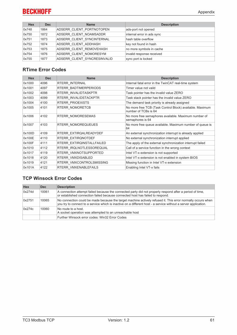
Appendix
Hex Dec Name Description0x748 1864 ADSERR_CLIENT_PORTNOTOPEN ads-port not opened0x750 1872 ADSERR_CLIENT_NOAMSADDR internal error in ads sync0x751 1873 ADSERR_CLIENT_SYNCINTERNAL hash table overflow0x752 1874 ADSERR_CLIENT_ADDHASH key not found in hash0x753 1875 ADSERR_CLIENT_REMOVEHASH no more symbols in cache0x754 1876 ADSERR_CLIENT_NOMORESYM invalid response received0x755 1877 ADSERR_CLIENT_SYNCRESINVALID sync port is locked
RTime Error CodesHex Dec Name Description
0x1000 4096 RTERR_INTERNAL Internal fatal error in the TwinCAT real-time system0x1001 4097 RTERR_BADTIMERPERIODS Timer value not vaild0x1002 4098 RTERR_INVALIDTASKPTR Task pointer has the invalid value ZERO0x1003 4099 RTERR_INVALIDSTACKPTR Task stack pointer has the invalid value ZERO0x1004 4100 RTERR_PRIOEXISTS The demand task priority is already assigned0x1005 4101 RTERR_NOMORETCB No more free TCB (Task Control Block) available. Maximum
number of TCBs is 640x1006 4102 RTERR_NOMORESEMAS No more free semaphores available. Maximum number of
semaphores is 640x1007 4103 RTERR_NOMOREQUEUES No more free queue available. Maximum number of queue is
640x100D 4109 RTERR_EXTIRQALREADYDEF An external synchronization interrupt is already applied0x100E 4110 RTERR_EXTIRQNOTDEF No external synchronization interrupt applied0x100F 4111 RTERR_EXTIRQINSTALLFAILED The apply of the external synchronization interrupt failed0x1010 4112 RTERR_IRQLNOTLESSOREQUAL Call of a service function in the wrong context0x1017 4119 RTERR_VMXNOTSUPPORTED Intel VT-x extension is not supported0x1018 4120 RTERR_VMXDISABLED Intel VT-x extension is not enabled in system BIOS0x1019 4121 RTERR_VMXCONTROLSMISSING Missing function in Intel VT-x extension0x101A 4122 RTERR_VMXENABLEFAILS Enabling Intel VT-x fails
TCP Winsock Error CodesHex Dec Description0x274d 10061 A connection attempt failed because the connected party did not properly respond after a period of time,
or established connection failed because connected host has failed to respond.0x2751 10065 No connection could be made because the target machine actively refused it. This error normally occurs when
you try to connect to a service which is inactive on a different host - a service without a server application.0x274c 10060 No route to a host.
A socket operation was attempted to an unreachable hostFurther Winsock error codes: Win32 Error Codes
TC3 Modbus TCP 61Version: 1.2