AFRL-RX-WP-TP-2010-4065 - DTIC · 2011-05-15 · AFRL-RX-WP-TP-2010-4065 MODIFIED EMBEDDED ATOM...
14
AFRL-RX-WP-TP-2010-4065 MODIFIED EMBEDDED ATOM METHOD STUDY OF THE MECHANICAL PROPERTIES OF CARBON NANOTUBE REINFORCED NICKEL COMPOSITES (POSTPRINT) Jamal Uddin, S.G. Srinivasan, Thomas R. Cundari, and Angela K. Wilson University of North Texas M.I. Baskes Los Alamos National Laboratory JANUARY 2010 Approved for public release; distribution unlimited. See additional restrictions described on inside pages STINFO COPY © 2010 The American Physical Society AIR FORCE RESEARCH LABORATORY MATERIALS AND MANUFACTURING DIRECTORATE WRIGHT-PATTERSON AIR FORCE BASE, OH 45433-7750 AIR FORCE MATERIEL COMMAND UNITED STATES AIR FORCE
Transcript of AFRL-RX-WP-TP-2010-4065 - DTIC · 2011-05-15 · AFRL-RX-WP-TP-2010-4065 MODIFIED EMBEDDED ATOM...

AFRL-RX-WP-TP-2010-4065
MODIFIED EMBEDDED ATOM METHOD STUDY OF THE MECHANICAL PROPERTIES OF CARBON NANOTUBE REINFORCED NICKEL COMPOSITES (POSTPRINT) Jamal Uddin, S.G. Srinivasan, Thomas R. Cundari, and Angela K. Wilson University of North Texas M.I. Baskes Los Alamos National Laboratory
JANUARY 2010
Approved for public release; distribution unlimited. See additional restrictions described on inside pages
STINFO COPY
© 2010 The American Physical Society
AIR FORCE RESEARCH LABORATORY MATERIALS AND MANUFACTURING DIRECTORATE
WRIGHT-PATTERSON AIR FORCE BASE, OH 45433-7750 AIR FORCE MATERIEL COMMAND
UNITED STATES AIR FORCE
i
REPORT DOCUMENTATION PAGE Form Approved
OMB No. 0704-0188
The public reporting burden for this collection of information is estimated to average 1 hour per response, including the time for reviewing instructions, searching existing data sources, gathering and maintaining the data needed, and completing and reviewing the collection of information. Send comments regarding this burden estimate or any other aspect of this collection of information, including suggestions for reducing this burden, to Department of Defense, Washington Headquarters Services, Directorate for Information Operations and Reports (0704-0188), 1215 Jefferson Davis Highway, Suite 1204, Arlington, VA 22202-4302. Respondents should be aware that notwithstanding any other provision of law, no person shall be subject to any penalty for failing to comply with a collection of information if it does not display a currently valid OMB control number. PLEASE DO NOT RETURN YOUR FORM TO THE ABOVE ADDRESS.
1. REPORT DATE (DD-MM-YY) 2. REPORT TYPE 3. DATES COVERED (From - To)
January 2010 Journal Article Postprint 01 January 2010 – 01 January 2010 4. TITLE AND SUBTITLE
MODIFIED EMBEDDED ATOM METHOD STUDY OF THE MECHANICAL PROPERTIES OF CARBON NANOTUBE REINFORCED NICKEL COMPOSITES (POSTPRINT)
5a. CONTRACT NUMBER
FA8650-08-C-5226 5b. GRANT NUMBER
5c. PROGRAM ELEMENT NUMBER
62102F 6. AUTHOR(S)
Jamal Uddin, S.G. Srinivasan, Thomas R. Cundari, and Angela K. Wilson (University of North Texas) M.I. Baskes (Los Alamos National Laboratory)
5d. PROJECT NUMBER
4349 5e. TASK NUMBER
20 5f. WORK UNIT NUMBER
LM114100 7. PERFORMING ORGANIZATION NAME(S) AND ADDRESS(ES) 8. PERFORMING ORGANIZATION
University of North Texas Denton, TX 76203
Los Alamos National Laboratory Materials Science and Technology Division, MS G755 Los Alamos, NM 87545
REPORT NUMBER
9. SPONSORING/MONITORING AGENCY NAME(S) AND ADDRESS(ES)
Air Force Research Laboratory
10. SPONSORING/MONITORING AGENCY ACRONYM(S)
Materials and Manufacturing Directorate Wright-Patterson Air Force Base, OH 45433-7750 Air Force Materiel Command United States Air Force
AFRL/RXLMD 11. SPONSORING/MONITORING AGENCY REPORT NUMBER(S)
AFRL-RX-WP-TP-2010-4065
12. DISTRIBUTION/AVAILABILITY STATEMENT
Approved for public release; distribution unlimited.
13. SUPPLEMENTARY NOTES
Journal article published in Physical Review B, Vol. 81 (2010). PAO Case Number: 88ABW-2009-3900; Clearance Date: 09 Sep 2009. © 2010 The American Physical Society. This work was funded in whole or in part by Department of the Air Force Contract FA8650-08-C-5226. The U.S. Government has for itself and others acting on its behalf a paid-up, nonexclusive, irrevocable worldwide license to use, modify, reproduce, release, perform, display, or disclose the work by or on behalf of the U.S. Government.
14. ABSTRACT
We report a computational study of the mechanical behavior of nanocomposite materials that are formed by incorporating aligned carbon nanotubes (CNTs) into a bulk nickel matrix. Mechanical properties of these novel materials are predicted and strain-stress relationships are investigated by atomistic calculations with interactions derived from the modified embedded-atom method (MEAM). The Ni/CNT composites are simulated using three single-walled nanotubes (SWCNTs) with varying diameters and a multi-walled (MWCNT) nanotube. Simulations predict that all Ni/CNT composites are mechanically stable. Within the small elastic deformation regime, the Ni/CNTs show a very high Young’s modulus compared to FCC nickel. In the longitudinal direction, the direction in which the CNTs are aligned, the single-crystal Ni/CNTs show a Young’s modulus ranging from 0.3 TPa for Ni/SWCNT(5,0) to 0.5 TPa for Ni/SWNCT(15,0). Ni/MWCNT shows the highest value of 0.6 TPa for Young’s modulus. These values are slightly lower than the corresponding pristine nanotubes.
15. SUBJECT TERMS
carbon nanotubes (CNTs), modified embedded-atom method (MEAN), single-walled nanotubes (SWCNTs)
16. SECURITY CLASSIFICATION OF: 17. LIMITATION OF ABSTRACT:
SAR
18. NUMBER OF PAGES
18
19a. NAME OF RESPONSIBLE PERSON (Monitor)
a. REPORT Unclassified
b. ABSTRACT Unclassified
c. THIS PAGE Unclassified
Christopher F. Woodward 19b. TELEPHONE NUMBER (Include Area Code)
N/A
Standard Form 298 (Rev. 8-98) Prescribed by ANSI Std. Z39-18

Modified embedded atom method study of the mechanical properties of carbon nanotubereinforced nickel composites
Jamal Uddin,1,2,* M. I. Baskes,3 S. G. Srinivasan,2,4 Thomas R. Cundari,1,2 and Angela K. Wilson1,2
1Department of Chemistry, University of North Texas, 1155 Union Circle #305070, Denton, Texas 76203, USA2Center for Advanced Scientific Computing & Modeling, University of North Texas, Denton, Texas 76203, USA
3Materials Science and Technology Division, Los Alamos National Laboratory, MS G755, Los Alamos, New Mexico 87545, USA4Department of Materials Science & Engineering, University of North Texas, Denton, Texas 76203, USA
�Received 12 October 2009; published 11 March 2010�
We report an atomistic simulation study of the behavior of nanocomposite materials that are formed byincorporating single-walled carbon nanotubes �SWCNTs�, with three different diameters, and a multiwalledcarbon nanotube �MWCNT� into a single-crystal nickel matrix. The interactions between carbon and nickelatoms are described by a modified embedded atom method potential. Mechanical properties of these nanocom-posite materials are predicted by atomistic calculations and compared with that of fcc nickel and pristine CNTs.Our simulations predict that all Ni/CNT composites studied in this work are mechanically stable. Their elasticproperties depend on the volume fraction and diameter of embedded CNTs. The single-crystal Young’s modu-lus �E11� of Ni/SWCNT composites exhibit a large increase in the direction of CNTs alignment compared tothat of a single-crystal nickel. However, a moderate but gradual decrease is seen for E22 and E33 in thetransverse directions with increase in CNT diameters. As a consequence, Ni/SWCNTs show a gradual decreasefor the polycrystalline Young’s, bulk and shear moduli with the increasing CNT diameters and volume frac-tions. These reductions, although moderate, suggest that enhancement of mechanical properties for polycrys-talline Ni/SWCNT nanocomposites are not achievable at any CNT volume fraction. The Ni/MWCNT com-posite with high CNT volume fraction shows the highest increase in E11. Unlike the E22 and E33 for Ni/SWCNTs, there is a significant increase in the E22 and the E33 for Ni/MWCNT. As a result, polycrystallineNi/MWCNT composites show slight increase in the elastic properties. This suggests that nickel nanocompos-ites with enhanced mechanical properties can be fabricated using large volume fractions of larger diameterMWCNTs. Depending on type, alignment and volume fraction, Ni/CNT composites show varying degrees ofelastic anisotropy and Poisson’s ratio compared to pure Ni. Simulation predicts strong adhesion at the Ni/CNTinterface and a significant interfacial stress transfer between CNT and Ni matrix.
DOI: 10.1103/PhysRevB.81.104103 PACS number�s�: 62.23.Pq, 81.40.Jj, 68.35.Gy, 62.20.de
I. INTRODUCTION
Carbon nanotubes �CNTs� are among the stiffest andstrongest materials.1 Their extremely small size, high aspectratios, and extraordinary structural and chemical stabilitymake CNTs a leading candidate for reinforcement fillers innanocomposite materials.2–6 As a result, there has been anincreasing scientific and technological interest in developingnanocomposites by dispersing CNTs into a metal matrix orby laser depositing metal matrix around the CNTs. Suchcomposites combine low density with high strength and stiff-ness, and enhanced electrical and thermal properties. Theseare particularly attractive for aerospace and other transporta-tion applications2–4 where there is a renewed emphasis onincreasing fuel efficiency by “light weighting” the transport-ers.
CNT-metallic composites offer distinct advantages overpolymeric composites for high-strength applications.5,6 Ku-zumaki et al. were the first to study a aluminum/CNTcomposite.7 Preparation and application of magnesium/CNTcomposites was also reported.8,9 The mechanical strength ofnickel/CNTs nanocomposites was studied recently by Sun etal.10 Some progress has also been made in the application ofatomistic simulations to predict the elastic and the mechani-cal properties of such composite materials. For example,molecular-dynamics �MD� simulations have been success-
fully applied to predict the elastic properties of polyethylene/CNT composites11 and other polymeric CNT composites.12
However, despite their potential superiority in mechanicalproperties, the development of CNT-metal matrix compositesremains in its infancy. Development of metal matrix compos-ites will be promoted from atomistic insights on the responseof their mechanical properties to chemical and materialmodifications.
Nickel is the primary ingredient of numerous aerospacesuperalloys,13,14 and therefore, is an attractive target for fab-rication of ultrastrength materials with CNTs. This researchinvestigates the mechanical properties of pristine CNTs, a fccnickel matrix, and Ni/CNT composites at different CNT vol-ume concentrations using quasistatic atomistic simulations.Elastic properties of solids are important because they relateto various fundamental solid-state properties. They deter-mine the response of the crystal to external forces, as char-acterized by elastic constants, bulk modulus, shear modulus,Young’s modulus, and Poisson’s ratio. Therefore, elasticproperties play an important part in determining the strengthof the materials. We have calculated these properties and theelastic anisotropy of Ni/CNT nanocomposite materials. Inter-atomic interactions are described using a modified embeddedatom method �MEAM� initially developed by Daw andBaskes15,16 and later modified by Baskes.17
PHYSICAL REVIEW B 81, 104103 �2010�
1098-0121/2010/81�10�/104103�12� ©2010 The American Physical Society104103-1
1
II. COMPUTATIONAL DETAILS
A. Theoretical formalism
In MEAM, the total energy of a system is given in thefollowing form:
E = �i�Fi��̄i� +
1
2 �j��i�
Sij�ij�Rij�� ,
where Fi is the embedding function for an atom i embeddedin a background electron density �̄i, Sij is the screening func-tion, and �ij�Rij� is the pair interaction between atoms i andj separated by a distance Rij. For the calculations of energy,the functional forms of Fi and �ij should be given. The back-ground electron density at each atomic site is computed bycombining several partial electron-density terms for variousangular contributions with weight factors t�h��h=0–3� �direc-tionality of bonding�. Each partial electron density is a func-tion of atomic configuration and atomic electron density. Theatomic electron densities �a�h��h=0–3� are given as
�a�h��R� = �0 exp�− ��h��R/re − 1�� ,
where �0, the atomic electron-density scaling factor, and ��h�,the decay lengths, are adjustable parameters, and re is thenearest-neighbor �NN� distance in the equilibrium referencestructure. A specific form is given to the embedding functionFi but not to the pair interaction �ij. Instead, a referencestructure where individual atoms occupy perfect-crystal atomsites is defined and the potential energy per atom of the ref-erence structure is estimated from the zero-temperature uni-versal equation of state by Rose et al.18 The value of the pairinteraction is evaluated from the known values of the poten-tial energy per atom and the embedding energy, which is afunction of the nearest-neighbor distance.
In the original MEAM,17 only the first nearest-neighborinteractions were considered. The second �2NN� and moredistant neighbor interactions were neglected by using strongmany-body screening function. The second-nearest-neighborinteractions have been included in the modified formalism byadjusting screening parameters Cmin to decrease the many-body screening effect. In addition, a radial cutoff function isalso applied to reduce calculation time. The MEAM for analloy system is based on the MEAM potentials for the com-ponent elements. The 2NN MEAM formalism19 gives 14 in-dependent model parameters for pure elements: four�Ec ,re ,B ,d� for the universal equation of state, seven���0� ,��1� ,��2� ,��3� , t�1� , t�2� , t�3�� for the electron density, one�A� for the embedding function, and two �Cmin,Cmax� for themany-body screening. The details of the MEAM formalismhave been published in the literature.17,20,21
B. Simulation methods
The MEAM potential parameters that describe the inter-atomic interactions for Ni, C, and Ni-C composites are listedin the Table I. It treats nickel, carbon, and the Ni-C interac-tions, and allows the formation of chemical bonds with ap-propriate atomic hybridization. Similar MEAM potential pa-rameters have been shown to model the catalytic growth ofCNTs on nickel nanocatalysts well.22 We performed molecu-lar static calculations at T=0 K. Periodic boundary condi-tions were applied along all three directions of the supercells.The Ni matrices and Ni/CNT composites were relaxed tominimize their energies.
The Ni/CNT composites were simulated using threesingle-walled nanotubes �SWCNTs� with varying diametersand a multiwalled �MWCNT� nanotube. We chose CNTswith zigzag structures for this study. SWCNTs with �5,0�,
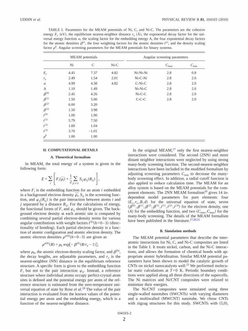
TABLE I. Parameters for the MEAM potentials of Ni, C, and Ni-C. The parameters are the cohesiveenergy Ec �eV�, the equilibrium nearest-neighbor distance re ��, the exponential decay factor for the uni-versal energy function �, the scaling factor for the embedding energy A, the four exponential decay factorsfor the atomic densities ��i�, the four weighting factors for the atomic densities t�i�, and the density scalingfactor �0. Angular screening parameters for the MEAM potentials for binary systems.
MEAM potentials Angular screening parameters
Ni C Ni-C Cmax Cmin
Ec 4.45 7.37 4.82 Ni-Ni-Ni 2.8 0.8
re 2.49 1.54 2.01 Ni-C-Ni 2.8 2.0
� 4.99 4.38 4.82 C-Ni-C 2.8 2.0
A 1.10 1.49 Ni-Ni-C 2.8 2.0
��0� 2.45 4.26 Ni-C-C 2.8 2.0
��1� 1.50 5.00 C-C-C 2.8 2.0
��2� 6.00 3.20
��3� 1.50 3.98
t�0� 1.00 1.00
t�1� 5.79 7.50
t�2� 1.60 1.04
t�3� 3.70 −1.01
�0 1.00 1.00
UDDIN et al. PHYSICAL REVIEW B 81, 104103 �2010�
104103-2
2

�10,0�, and �15,0� chiral indices and tubular diameters of3.97 Å, 7.86 Å, and 11.77 Å, respectively, were studied.These CNTs were embedded in a supercell containing 37 044nickel atoms. The atomic structure and the crystallographicorientation of the SWCNTs and supercells are shown in Figs.1 and 2. This supercell has 21�21�21 unit cells and isapproximately 7.4 nm�7.4 nm�7.4 nm in three perpen-dicular directions.
As the CNT volume fraction is an important variable indetermining the composite mechanical properties, we usedtwo different concentrations of each CNTs for Ni/CNT com-posites. The three supercells had a CNT volume fraction of0.83%, 1.85%, and 3.37% when single CNTs were used.When four CNTs are embedded in each supercell, the CNT
volume fractions were increased to 3.33%, 7.40%, and13.46% for �5,0�, �10,0�, and �15,0� SWCNTs, respectively.Since the Ni matrix does not penetrate the hollow inside ofCNT, we treated the CNTs as solid beams for volume frac-tions calculations.
The MWCNTs were built by inserting SWCNTs into eachother coaxially while maintaining their individual periodic-ity. For composites made with MWCNTs, the CNT volumefractions were similar to the volume fractions ofSWCNT�15,0�. For example, Fig. 2�d� shows MWCNT thatfits the periodicity of fcc Ni matrix. The wall thickness ofSWCNTs were assumed to be 0.32 nm based on electron-density distribution calculations23 and similar methods.24,25
To simulate the Ni/CNTs nanocomposites with low CNTvolume fractions, four different single-crystal Ni supercellscontaining a hollow cylindrical void at the center were built.For studying nanocomposites with high CNT volume frac-tions, four different single-crystal Ni supercells were builtwith four cylindrical voids approximately equidistant to eachother. The cylindrical void runs from one face to the oppositeface of the supercell with the cylinder axis aligned parallel tothe supercell �001� direction �a axis�. The radii of these voidswere chosen to fit SWCNT�5,0�, SWCNT�10,0�,SWCNT�15,0�, and the MWCNT, leaving an appropriateamount of space for Ni-C interatomic bonding. The nano-composites were formed by embedding the CNTs into thevoided Ni supercells. The resulting composites contain a ho-mogeneous distribution of aligned CNTs. Two simulationcells with embedded CNTs are shown in Figs. 2�b� and 2�c�.
Mechanical properties and stress-strain relationships weredetermined from the relaxed configurations. Elastic constantsfor Ni and Ni/CNTs were calculated from strain-energy-applied strain relationships by fitting the strain energy pervolume to a parabola. Strains of 0.1% deformation aroundthe fully minimized structures were chosen to maintain de-formations within the linear elastic regime. For each defor-mation step �0.0002 step size�, we minimized system energyby relaxing positions of all atoms. Nine-independent elasticconstants �c11, c22, c33, c12, c23, c31, c44, c55, and c66� andthree independent constants �c11, c12, and c44� of Ni/CNTsand pure fcc Ni were determined in this study. The direction-dependent Young’s modulus �E�,26 which measures the stiff-ness of a material, was calculated from the slope of thestrain-stress curves for pristine CNTs. Young’s modulus forCNTs with only longitudinal response were calculated with0.0002 increments in the applied strain. For Ni matrix andNi/CNT systems, E was calculated from the appropriatesingle-crystal elastic constants.
III. RESULTS AND DISCUSSION
A. Pristine CNTs
Table II shows that the Young’s moduli of individualCNTs obtained in our work agree well with numerous pub-lished experimental28,30,31,33 and theoretical values.22,24,27,43
Most of the experimental measurements of E were carriedout for MWCNTs. Also, Young’s moduli of SWCNTs show alarge variation from 0.78 to 3.6 TPa and that only a fewexperimental results are available.33,35,37,44,45 Our calculated
FIG. 1. �Color online� Space filling unit cells of �n,0� CNTs.SWCNT and MWCNT refer to single-walled and multiwalled CNT.�a� SWCNT�5,0�, �b� SWCNT�10,0�, and �c� SWCNT�15,0�.MWCNT in �d� is built by assembling SWCNT�5,0�,SWCNT�10,0�, and SWCNT�15,0� nanotubes coaxially. The ap-proximate tubular height for the unit cell is 4.26 Å for allnanotubes.
(a)
(b) (c)
(d)
FIG. 2. �Color online� Atomistic structures and the crystallo-graphic orientations of the supercells. �a� Fully minimized purenickel �face-centered-cubic lattice�, �b� nickel matrix with an em-bedded MWCNT, �c� nickel matrix with four embedded MWCNT,�d� full extent of a MWCNT embedded in the nickel supercell.Periodic boundary conditions are applied for pure nickel and Ni/CNT matrix along the three dimensions.
MODIFIED EMBEDDED ATOM METHOD STUDY OF THE… PHYSICAL REVIEW B 81, 104103 �2010�
104103-3
3

E of 832 GPa for SWCNT�10,0� agrees with the value cal-culated by Xiao et al. �820 GPa�, Agrawal et al.27 �900 GPa�,and Lu �975 GPa�.24 Our results from the same CNT is alsoin reasonable agreement with the values of 965 and 972 GPacalculated using tight-binding and density-functional theory,respectively, by Ogata and Shibutani.40 On the contrary,Hernández and coworkers36 reported a much greater value of1220 GPa for this nanotube using tight-binding MD. Theselarge differences may be attributed to differences in the CNTvolume estimation due to variations in effective CNT wallthickness. In spite of extensive studies, the variations in wallthickness of CNTs remain an unresolved question.46
B. Ni/CNT composites:
1. Single-crystal elastic constants
A necessary condition for mechanical stability of a struc-ture is that its strain energy must be positive against arbitrarybut small homogeneous elastic deformations. For an ortho-rhombic crystal, this imposes the following constraints:47
c11+c22�2c12, c22+c33�2c23, c11+c33�2c31, cii�0 �i=1–6�, and c11+c22+c33+2c12+2c23+2c31�0. These crite-ria simplify to c11�0, c44�0 c11+2c12�0, and c11−c12�0 for cubic crystals such as fcc Ni. Hence, we examinedthe mechanical stability of the Ni/CNT composites using ap-propriate single-crystal elastic constants for composites withboth low and high CNT volume fractions. The calculatedvalues for elastic constants cij are summarized in Table III.
For single-crystal Ni, the MEAM calculated values forc11, c12, and c44 agree well with experiments.48,49 The shearelastic constants c11−c12 and c11+2c12 determine stability.
Physically, c44 plays a subtle role and represents the resis-tance of the system to a shear deformation such as in the�100� plane in the �010� direction. Similarly, �c11−c12� /2represents the resistance to shear deformation across, for ex-ample, a �110� plane in the �11̄0� direction. Similar observa-tions hold for an orthorhombic crystal. From the Table IIIdata, it is observed that for Ni/CNT composites, the cii �i=1–6�, c11+c22−2c12, c22+c33−2c23, c11+c33−2c13, andc11+c22+c33+2c12+2c23+2c13 are all positive, and thus itcan be reasonably concluded that Ni/CNTs composites aremechanically stable. This is an encouraging result for thefabrication of nanocomposite materials by embedding theCNTs in metal matrices.
For Ni/CNTs, c11 show moderate increase in compositeswith low CNT volume fractions and significantly large in-crease in composites with high CNT volume fractions com-pared to that of pure Ni. These increases depend on the typeand diameter size of the embedded nanotubes. For example,composites Ni/SWCNT�5,0�, Ni/SWCNT�10,0�, and Ni/SWCNT�15,0� show an increase of 5, 10, and 12 GPa, re-spectively, for low CNT volume fraction and 19, 39, and 42GPa, respectively, for high CNT volume fraction. Ni/MWCNT shows the largest increase in c11 than for any of theNi/SWCNTs. In this case, c11 shows an increase of 30 GPaand 109 GPa, respectively, for low and high CNT volumefractions compared to that of Ni. In the transverse directions,c22 or c33 show gradual decrease for Ni/SWCNTs comparedto pure Ni. However, in these cases, composites with higherCNT volume fractions show a larger decrease compared tocomposites with low CNT volume fractions. Interestingly,the Ni/MWCNT nanocomposite shows very small or nochanges for c22 or c33.
TABLE II. Young’s modulus �E11� �in GPa� for single-walled �SWCNTs� and a multiwalled �MWCNT� carbon nanotubes obtained fromour MEAM Ni-C potential are tabulated and compared with the literature values.
This work Previous calculations Experiments
820 �Xiao et al., MD�a
900 �Agrawal et al., MD�b 270–900 �Yu et al.�c
5500 �Yakobson, MD�d 790 �Li et al.�e
552 �SWCNT�5,0�� 974 �Lu, MD�f 900 �Demcyzek et al.�g
832 �SWCNT�10,0�� 1325 �Cheng and Gao, MD�h 816�410 �Salvetat et al.�i
892 �SWCNT�15,0�� 1238 �Jin and Yuan, Force-Field�j 1200 �Tombler et al.�k
740 �MWCNT� 1220 �Hernández et al., TB-MD�l 1250 �Krishnan et al.�m
4700 �Tu, LDA�n
764 �Zhou et al., LCAO-MO cluster�o
965, 972 �Ogata and Shibutani, TB, DFT�p
1470 �Pullen, GGA�q
1060 �Li and Chou, MM�r
899�5,0�, 916�10,0�, 923�15,0� �Meo and
Rossi, MM-FEM�s
aReference 22.bReference 27.cReference 28.dReference 29.eReference 30.
fReference 24.gReference 31.hReference 32.iReference 33.jReference 34.
kReference 35.lReference 36.mReference 37.nReference 38.oReference 39.
pReference 40.qReference 41.rReference 32.sReference 42.
UDDIN et al. PHYSICAL REVIEW B 81, 104103 �2010�
104103-4
4

In the composites with SWCNTs, c12 and c13 decrease forboth low and high CNT concentrations, which depend on theCNT diameters and the CNT volume fractions. A larger de-crease is seen for composites with larger CNT diameters. Forexample, in the case of Ni/SWCNT�15,0� with high CNTvolume fraction, the value for c12 and c13 is found to be 18GPa less than that of Ni. The c23 on the other hand, remainsimilar to that of Ni, with a few exceptions, where a minuteincrease is seen. For the composites with the MWCNT, c12and c13 decrease for both low and high CNT volume frac-tions. For c23, however, a small increase is seen for bothvolume fractions. The values of c44, c55, and c66 decrease inthe composites compared to pure Ni �125 GPa� and dependon the CNT concentration in the composites. A similar trendis seen for c55 and c66, although these show less variationthan c44. The Ni/MWCNT composites also show similarCNT concentration dependence for these elastic parameters,however, the decrease in c44 is less in a relative sense. Notethat c44, c55, and c66 are equivalent to the shear modulus �G�.
To study the angular anisotropy of the elastic constants inNi/CNT, we performed calculations in which the CNT isrotated about its tubular axis. Elastic constants from thesecalculations are similar to the original unrotated systems.While lack of anisotropy merits further investigation, the oc-currence of a regular interfacial structural pattern seems un-likely because this interface forms between the large periph-eral surface of the CNT that runs through the entire 7.4 nmlength of the unit cell and the irregular curvature of the Nimatrix in the perpendicular directions.
The Young’s modulus �E� along the normal direction ofthe lattice plane is defined as the ratio of the stress to thestrain along that direction. E11 �E001�, E22 �E100�, and E33�E010� were calculated for cubic and orthorhombic latticesalong the principal �a, b, and c� axes. Poisson’s ratio ��n ,m�of an elastic solid for any two specified general orthogonalunit vectors n and m is defined as −�m� /�n�, where �m� isthe transverse strain in the direction m and �n� is the axial
strain in the direction n due to a uniaxial tension of thematerial along the direction n. With the exception of isotro-pic elastic materials, Poisson’s ratio for an anisotropic elasticmaterial depends on the choice of n and m and was calcu-lated from the elastic compliance values.
Figure 3 presents the calculated values of E11, E22, andE33 for Ni and Ni/CNT composites for two different CNTvolume fractions. For pure Ni, we calculated E of 136.9 GPaalong the major directions. This agrees reasonably well withan experimental value of 120 GPa.49 For composites, in the
TABLE III. Single-crystal elastic constants cij �in GPa�, and derived quantities c11+c22−2c12, c22+c33−2c23, c11+c33−2c13, and c11
+c22+c33+2c12+2c23+2c13 for pure fcc nickel and the Ni/SWCNTs and Ni/MWCNT composites with low and high CNT volume fractions.
Ni�fcc� Ni/SWCNT�5,0� Ni/SWCNT�10,0� Ni/SWCNT�15,0� Ni/MWCNT
Low High Low High Low High Low High
c11 247.1 251.9 266.1 256.7 284.0 258.8 289.4 276.9 356.1
c22 247.1 246.0 243.6 245.4 241.5 243.2 233.4 245.7 243.9
c33 247.1 246.0 243.9 245.2 240.6 243.4 233.6 246.3 247.5
c12 147.5 146.6 144.0 145.5 139.7 142.7 129.7 142.9 132.8
c23 147.5 148.3 150.5 147.9 148.8 147.7 147.5 149.1 149.6
c13 147.5 148.0 144.9 145.5 140.1 142.7 129.5 143.6 133.8
c44 125.4 123.7 118.6 118.5 99.6 114.5 83.8 118.2 109.5
c55 125.4 121.4 112.3 121.9 113.1 120.7 109.1 118.4 104.7
c66 125.4 121.4 112.3 121.9 113.1 120.7 109.1 118.4 104.8
c11+c22−2c12 199.3 204.7 221.7 211.1 246.1 216.6 263.8 236.8 334.3
c22+c33−2c23 199.3 201.3 220.1 210.9 244.4 216.8 263.6 236.1 294.9
c11+c33−2c13 199.3 195.5 186.5 194.8 184.5 191.2 172.0 193.8 184.5
c11+c22+c33+2c12+2c23+2c13 1626.2 1630.3 1632.5 1625.1 1623.3 1611.6 1569.8 1640.0 1728.7
FIG. 3. �Color online� Calculated Young’s modulus �GPa� forfcc Ni and Ni/CNT composites with two different CNT fractions.The E001 �E11� is the Young’s modulus for uniaxial loading parallelto CNT axis, the E010 �E22� or E100 �E33� are the Young’s moduli inthe directions transverse to the CNT axis in single-crystal systems,and Epolycrystalline is the Young’s modulus for polycrystalline aggre-gates. Composites with low CNT fractions are designated as CL andcomposites with high CNT fractions are designated as CL.
MODIFIED EMBEDDED ATOM METHOD STUDY OF THE… PHYSICAL REVIEW B 81, 104103 �2010�
104103-5
5
longitudinal direction �the direction of CNT alignments�, E11�E11
L � show a dramatic increase and follows the trend
Ni/SWCNT�5,0� Ni/SWCNT�10,0�
Ni/SWCNT�15,0� Ni/MWCNT.
These increases depend on the CNT volume fractions of thecomposites and approximately proportional to the CNT vol-ume fractions. Similar trend is seen for E22 �E22
T � and E33�E33
T �. For SWCNTs, a slight but gradual decrease is seen forthe E values depending on the CNT diameter and volumefractions. Interestingly, E22
T and E33T increases for Ni/
MWCNT. For example, in this case, E22T �or E33
T � is increasedby 2 GPa for low CNT volume fraction and an average of 8GPa for high CNT volume fraction, respectively, which sug-gests that Ni/CNT composites with significantly largerMWCNT diameter and with high CNT volume fractionsmight increase the Young’s modulus in both longitudinal andtransverse directions. However, verification of this hypoth-esis is beyond the scope of the present paper.
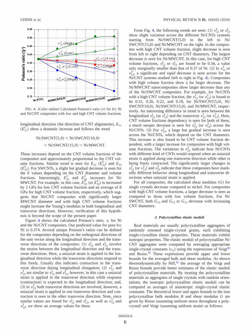
Figure 4 shows the calculated Poisson’s ratio, �, for Niand the Ni/CNT composites. Our predicted value for pure fccNi is 0.374. Several unique Poisson’s ratios can be definedfor the composites depending on the orthogonal directions ofthe unit vector along the longitudinal direction and the trans-verse directions of the composites: �1� �12
L and �13L involve
the strains between the longitudinal direction and the trans-verse directions. Here, a uniaxial strain is applied in the lon-gitudinal direction while the transverse directions respond tothis freely. Usually this indicates contraction in the trans-verse direction during longitudinal elongation; �2� �12
T and�13
T are similar to �12L and �13
L , however, in this case a uniaxialstrain is applied in the transverse direction while response�contraction� is expected in the longitudinal direction; and,�3� in �23
T both transverse directions are involved, however, auniaxial strain is applied in one transverse direction and con-traction is seen in the other transverse direction. Note, sincesimilar values are found for �12
L and �13L , as well as �12
T and�13
T , we show an average values for these.
From Fig. 4, the following trends are seen: �1� �12L or �13
L
show slight variation across the different Ni/CNTs systemsstarting from Ni/SWCNT�5,0� in the left to Ni/SWCNT�15,0� and Ni/MWCNT on the right. In the compos-ites with high CNT volume fraction, slight decrease is seenfrom left to right depending on CNT diameters. The largestdecrease is seen for Ni/MWCNT. In this case, for high CNTvolume fractions, �12
L or �13L are found to be 0.34, a value
only marginally smaller than that of 0.37 of Ni. �2� In �12T or
�13T , a significant and rapid decrease is seen across for the
Ni/CNT systems studied �left to right in Fig. 4�. Compositeswith high volume fraction show a far larger decrease. TheNi/MWCNT nanocomposites show larger decrease than anyof the Ni/SWCNT composites. For example, for Ni/CNTswith a high CNT volume fraction, the �12
T �or �13T � is found to
be 0.31, 0.26, 0.22, and 0.18, for Ni/SWCNT�5,0�, Ni/SWCNT�10,0�, Ni/SWCNT�15,0�, and Ni/MWCNT, respec-tively. An interesting difference in trend is seen between thelongitudinal �12
L �or �13L � and the transverse �12
T �or �13T �. Here,
CNT volume fractions dependency is seen for both of these,a much steeper decrease is seen for �12
T �or �13T � across the
Ni/CNTs. �3� For �23T , a large but gradual increase is seen
across the Ni/CNTs, which depend on the CNT diameters.This increase is also found to be CNT volume fraction de-pendent, with a larger increase for composites with high vol-ume fractions. The variations in �23
T indicate how Ni/CNTswith different kind of CNTs would respond when an uniaxialstrain is applied along one transverse direction while other isbeing freely contracted. The significantly larger changes in�12
T �or �13T � and �23
T indicate that these composites have mark-edly different behavior along longitudinal and transverse di-rections when uniaxial strain is applied.
For all composites, the calculated shear modulus �G� forsingle crystals decrease compared to nickel. For compositeswith high CNT volume fractions, a larger decrease is seen ascompared to those with low volume fractions. For Ni/SWCNT, both G23 and G13 or G12 decrease with increasingCNT diameters.
2. Polycrystalline elastic moduli
Real materials are usually polycrystalline aggregates ofrandomly oriented single-crystal grains, each exhibitingsingle-crystalline elastic properties. These materials exhibitisotropic properties. The elastic moduli of polycrystalline Ni/CNT aggregates were computed by averaging appropriatesingle-crystal constants �cij� using the expressions of Voigt50
and Reuss.51 These expressions provide upper and lowerbounds for the averaged bulk and shear modulus. As shownthermodynamically by Hill,52 the average of the Voigt andReuss bounds provide better estimates of the elastic moduliof polycrystalline materials. By treating the polycrystallinematerials as aggregates of single crystals with random orien-tations, the isotropic polycrystalline elastic moduli can becomputed as averages of anisotropic single-crystal elasticconstants. The theoretical lower and upper bounds to the truepolycrystalline bulk modulus B and shear modulus G aregiven by Reuss �assuming uniform stress throughout a poly-crystal� and Voigt �assuming uniform strain� as follows:
FIG. 4. �Color online� Calculated Poisson’s ratio ��� for fcc Niand Ni/CNT composites with low and high CNT volume fractions.
UDDIN et al. PHYSICAL REVIEW B 81, 104103 �2010�
104103-6
6

BR = 1/�s11 + s33 + s33 + 2�s12 + s23 + s13�� ,
BV = 1/9�c11 + c33 + c33� + 2/9�c12 + c23 + c13� ,
GR = 15/�4�s11 + s33 + s33� − 4�s12 + s23 + s13�
+ 3�s44 + s55 + s66�� ,
GV = �c11 + c22 + c33 − c12 − c23 − c13�/15 + �c44 + c55 + c66�/5,
where sij are elastic compliances and their values can beobtained through an inversion of the elastic constant matrix,S=C−1. We estimated the true polycrystalline values by usingthe Voigt and Reuss, and Hill �VRH� approximations:52 BH= �BR+BV� /2 and GH= �GR+GV� /2. The average Young’smodulus and Poisson’s ratio for polycrystalline aggregatescan then be calculated as Epolycrystalline= �9BHGH� / �3BH+GH� and �polycrystalline= �3BH−2GH� / �6BH+2GH�.
Table IV shows the calculated bulk �BH� and shear �GH�moduli for the polycrystalline aggregates of Ni and the Ni/CNT composites using VRH approximations. We discuss theresults obtained using the Hill average only. The calculatedBH for polycrystalline nickel is identical to that of the corre-sponding single crystal and also agrees well with experiment.The bulk modulus of Ni determined from the Birch-Murnaghan equation of state is also found to be identical.For Ni/CNT composites, no significant changes are seen inBH except for Ni/CNT, which show a slight increase of 1GPa and 4 GPa, respectively, for low and high CNT volumefractions. The shear modulus GH, which measures the abilityof a material to resist transverse deformations, decreasesslightly for Ni/SWCNTs as compared to pure Ni. For fccnickel, the calculated GH is found to be 87 GPa, whichagrees well with experiment.49 For Ni/MWCNT, these valuesincrease slightly and depend on CNT volume fractions.
Pugh53 introduced the ratio between the bulk and shearmodulus, BH /GH, for polycrystalline phases as a measure offracture/toughness in metals by considering that the shearmodulus GH represents the resistance to plastic deformationwhile the bulk modulus BH represents the resistance to frac-ture. A high BH /GH value is associated with ductility while alow value is associated with brittleness. The critical valuethat separates ductile and brittle materials is about 1.75. Ourcalculated BH /GH for pure nickel is 2.1. For Ni/CNT com-posites, similar BH /GH values are found. By considering thebulk modulus as a measure of the average bond strength and
the shear modulus as a measure of the resistance to a changein bond angle by an external force, Tanaka et al.54 proposedthat GH /BH represents the relative directionality of the bond-ing in the material. It can be seen that there is a slight de-crease in these ratios for Ni/SWCNTs. Composites with highCNT volume fractions show a greater decrease. For Ni/MWCNT, there is no observable change with pure Ni. TheBH /GH and the GH /BH values indicate that CNT do not sig-nificantly alter the above-mentioned properties as comparedto fcc Ni.
The average Young’s modulus for polycrystalline aggre-gates �Epolycrystalline� calculated from the Hill’s formula forpure Ni and the Ni/CNTs are presented graphically in Fig. 3.The Young’s modulus in longitudinal E001 �E11� and trans-verse directions, E010,E100 �E22,E33� determined for single-crystal specimens are also compared. For, Ni the value cal-culated using Hill’s average is 222 GPa. This value is inexcellent agreement with the experimental value of213.1�21.2 GPa, obtained for coarse-grained polycrystal-line aggregates.49 In Ni/SWCNT composites, Epolycrystalline
FIG. 5. �Color online� Young’s modulus in longitudinal direc-tion, E11, �in GPa� simulated and calculated using the rule-of-mixture �RoM� for Ni/SWCNT and Ni/MWCNT composites withlow- and high CNT volume fractions. The straight lines for eachCNT type are obtained by fitting the RoM data at low and highCNT volume fractions. The simulated values for each composite arepresented with symbols.
TABLE IV. Polycrystalline bulk �B� and shear �G� moduli calculated �in GPa� for Ni and nickel/CNT composites. The anisotropies of thebulk modulus along the a axis with respect to the b and c axes are also given. The values are shown for Voigt �V�, Reuss �R�, and Hill �H�approximations. Low and High are the composites low and high CNT volume fractions.
Ni�fcc� GV �95.2� BV �180.7� GR �78.04� BR �180.7� GH �86.6� BH �180.7�
Low High Low High Low High Low High Low High Low High
Ni/SWCNT�5,0� 93.3 89.6 180.9 181.4 77.6 77.0 181.1 181.2 85.5 83.3 181.1 181.3
Ni/SWCNT�10,0� 93.0 87.7 180.6 180.4 78.3 77.5 180.5 179.7 85.6 82.6 180.5 180.0
Ni/SWCNT�15,0� 92.0 83.7 179.1 174.4 78.1 74.4 179.0 173.7 85.0 79.1 179.0 174.1
Ni/MWCNT 93.2 92.6 182.2 186.7 80.7 83.8 182.0 183.2 86.9 88.2 182.0 184.9
MODIFIED EMBEDDED ATOM METHOD STUDY OF THE… PHYSICAL REVIEW B 81, 104103 �2010�
104103-7
7

decreases with increasing CNT diameter. Composites withhigher CNT volume fractions show larger decreases. Ni/MWCNT does not show an appreciable change inEpolycrystalline for the composite with low volume fraction anda slight increase for composites with high volume fractionsof CNT. Generally, Epolycrystalline is much larger in magnitudesthan the single crystal E. From these trends, we can concludethat embedding SWCNTs in the Ni matrix will decrease thepolycrystalline Young’s modulus Epolycrystalline. On the con-trary, the polycrystalline Young’s modulus might increasewhen MWCNTs are embedded in the Ni matrix.
Our calculated Poisson’s ratio for polycrystalline nickel is0.293. This is in reasonable agreement with the experimentalvalue of 0.31.55 Surprisingly, we find similar values for Ni/CNT composites. For example, for Ni/SWCNT�5,0�, Ni/SWCNT�10,0�, Ni/SWCNT�15,0�, and Ni/MWCNT compos-ites with higher CNT fractions, the calculated Poisson’sratios are 0.301, 0.301, 0.303, and 0.317, respectively. Theyare 0.296, 0.295, 0.295, and 0.294 for the same compositeswith lower CNT volume fractions. The calculated Poisson’sratios indicate that the Ni/CNT composites remain similarlystable against shear as compared to pure Ni.
3. Elastic anisotropy
Elasticity describes the response of a crystal under exter-nal strain and provides key information about the bondingcharacteristic between adjacent atomic planes and the aniso-tropic character of the solid.26 The shear anisotropic factorsmeasure the degree of anisotropy in the bonding betweenatoms in different planes. Anisotropy in orthorhombic mate-rials arises from the anisotropy in their shear and linear bulkmoduli.
The shear anisotropic factor is defined as
A1 = 4c44/�c11 + c33 − 2c13�
for the �100 shear planes in 011� and 010� directions,
A2 = 4c55/�c22 + c33 − 2c23�
for the �010 shear planes in 101� and 001� directions, and
A3 = 4c66/�c11 + c22 − 2c12�
for the �001 shear planes in 110� and 010� directions. Foran isotropic crystal, the factors A1, A2, and A3 must be one.The deviation from one is a measure of the degree of theelastic anisotropy of crystals.
The anisotropy of the bulk modulus along the a axis withrespect to b and c axes can be estimated using the followingequations:
ABb=
Ba
Bb, ABc
=Ba
Bc.
Note that a value of unity for these two fractions indicateselastic isotropy. In the above equations, Ba, Bb, and Bc arethe bulk moduli along different crystal axes, are defined as
Ba = adP
da, Bb = b
dP
db, and Bc = c
dP
dc.
A practical measure of elastic anisotropy for polycrystallinematerials is defined as follows:
AB =�BV − BR��BV + BR�
and AG =�GV − GR��GV + GR�
,
where B and G are the bulk and shear moduli and the sub-scripts V and R denote the Voigt and Reuss limits. For theseexpressions, a value of zero identifies elastic isotropy and avalue of 1 �100%� is the largest possible anisotropy.
The bulk modulus and the directional bulk modulus aregiven in Table V. Note that the CNTs are aligned along the aaxis. It is clear that Ba is higher than Bb and Bc, which arenearly identical. In the composites, Ba increases with volumefraction of CNT while Bb and Bc both decrease as comparedto Ni. The directional bulk modulus of Ni is 542 GPa alongall three axes. For Ni/MWCNT composites, the highest �817GPa� and lowest �462 GPa� values for Ba and Bb or Bc areseen for high CNT volume fractions. For Ni/SWCNTs, de-pendencies on the diameters are also seen.
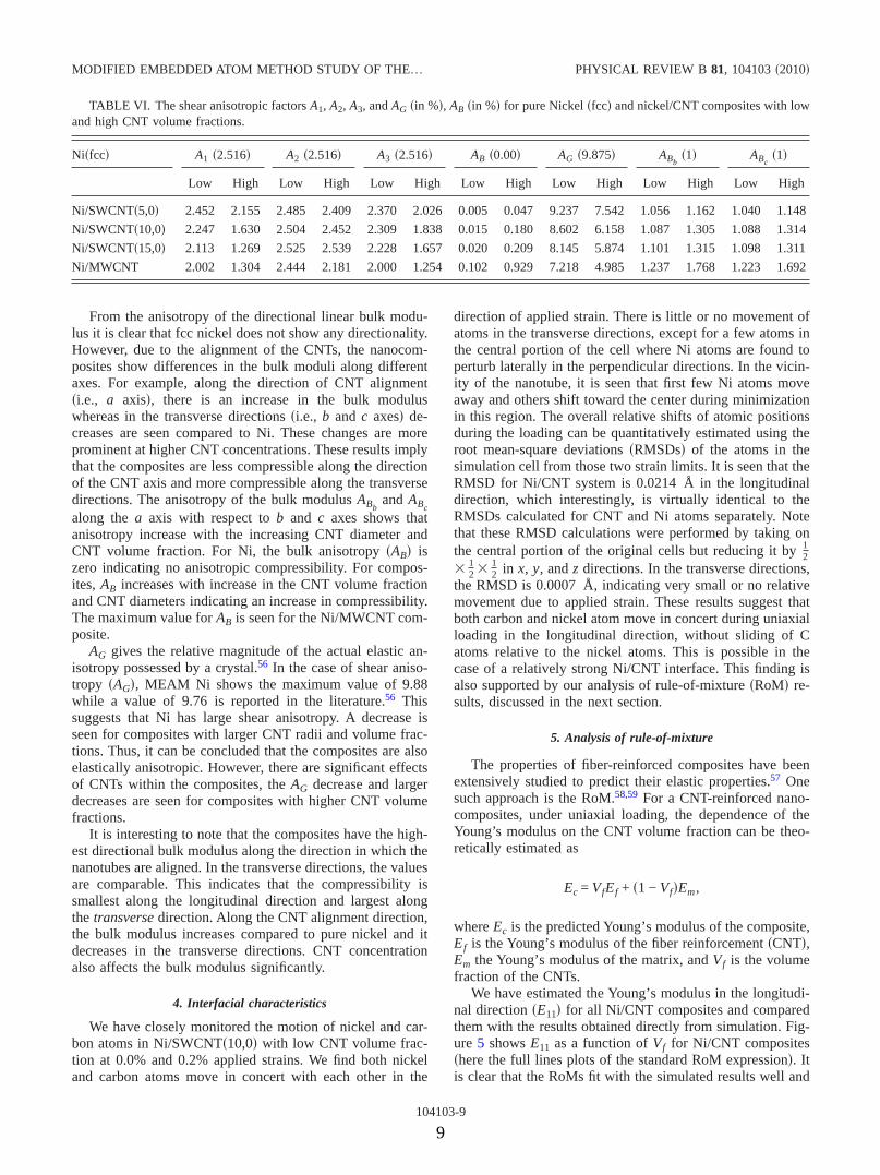
The shear anisotropic factors are given in Table VI. Forfcc Ni, we calculated a shear anisotropic factor As is 2.52while the value reported in the literature56 value is 2.63. Thisindicates significant deviation from isotropy. We also see thatthe shear anisotropic factors A1, A2, and A3 for the compos-ites depend on CNT concentrations. Similar changes are seenfor A1 and A3 where these values are found to be lower thanpure nickel. A steeper decrease for these is seen for compos-ite with high CNT volume fractions. For SWCNTs, a largerdecrease is seen for CNTs with larger diameter. A2 for thecomposites remains similar to that for pure nickel.
TABLE V. The isotropic bulk modulus �B in GPa� and directional bulk modulus along the orthorhombiccrystallographic axes a, b, and c �Ba, Bb, and Bc� for pure Nickel �fcc� and nickel/CNT composites. Low andHigh are the composites low and high CNT volume fractions.
Ni�fcc� B �180.7� Ba �542.1� Bb �542.1� Bc �542.1�
Low High Low High Low High Low High
Ni/SWCNT�5,0� 181.1 181.2 560.8 599.8 530.9 516.3 538.8 522.5
Ni/SWCNT�10,0� 180.5 179.2 573.3 650.5 527.4 498.3 526.6 495.1
Ni/SWCNT�15,0� 179.0 173.7 572.6 629.5 520.4 479.7 521.2 479.9
Ni/MWCNT 182.0 183.2 629.3 817.4 508.6 462.2 514.5 482.9
UDDIN et al. PHYSICAL REVIEW B 81, 104103 �2010�
104103-8
8
From the anisotropy of the directional linear bulk modu-lus it is clear that fcc nickel does not show any directionality.However, due to the alignment of the CNTs, the nanocom-posites show differences in the bulk moduli along differentaxes. For example, along the direction of CNT alignment�i.e., a axis�, there is an increase in the bulk moduluswhereas in the transverse directions �i.e., b and c axes� de-creases are seen compared to Ni. These changes are moreprominent at higher CNT concentrations. These results implythat the composites are less compressible along the directionof the CNT axis and more compressible along the transversedirections. The anisotropy of the bulk modulus ABb
and ABcalong the a axis with respect to b and c axes shows thatanisotropy increase with the increasing CNT diameter andCNT volume fraction. For Ni, the bulk anisotropy �AB� iszero indicating no anisotropic compressibility. For compos-ites, AB increases with increase in the CNT volume fractionand CNT diameters indicating an increase in compressibility.The maximum value for AB is seen for the Ni/MWCNT com-posite.
AG gives the relative magnitude of the actual elastic an-isotropy possessed by a crystal.56 In the case of shear aniso-tropy �AG�, MEAM Ni shows the maximum value of 9.88while a value of 9.76 is reported in the literature.56 Thissuggests that Ni has large shear anisotropy. A decrease isseen for composites with larger CNT radii and volume frac-tions. Thus, it can be concluded that the composites are alsoelastically anisotropic. However, there are significant effectsof CNTs within the composites, the AG decrease and largerdecreases are seen for composites with higher CNT volumefractions.
It is interesting to note that the composites have the high-est directional bulk modulus along the direction in which thenanotubes are aligned. In the transverse directions, the valuesare comparable. This indicates that the compressibility issmallest along the longitudinal direction and largest alongthe transverse direction. Along the CNT alignment direction,the bulk modulus increases compared to pure nickel and itdecreases in the transverse directions. CNT concentrationalso affects the bulk modulus significantly.
4. Interfacial characteristics
We have closely monitored the motion of nickel and car-bon atoms in Ni/SWCNT�10,0� with low CNT volume frac-tion at 0.0% and 0.2% applied strains. We find both nickeland carbon atoms move in concert with each other in the
direction of applied strain. There is little or no movement ofatoms in the transverse directions, except for a few atoms inthe central portion of the cell where Ni atoms are found toperturb laterally in the perpendicular directions. In the vicin-ity of the nanotube, it is seen that first few Ni atoms moveaway and others shift toward the center during minimizationin this region. The overall relative shifts of atomic positionsduring the loading can be quantitatively estimated using theroot mean-square deviations �RMSDs� of the atoms in thesimulation cell from those two strain limits. It is seen that theRMSD for Ni/CNT system is 0.0214 Å in the longitudinaldirection, which interestingly, is virtually identical to theRMSDs calculated for CNT and Ni atoms separately. Notethat these RMSD calculations were performed by taking onthe central portion of the original cells but reducing it by 1
2�
12 �
12 in x, y, and z directions. In the transverse directions,
the RMSD is 0.0007 Å, indicating very small or no relativemovement due to applied strain. These results suggest thatboth carbon and nickel atom move in concert during uniaxialloading in the longitudinal direction, without sliding of Catoms relative to the nickel atoms. This is possible in thecase of a relatively strong Ni/CNT interface. This finding isalso supported by our analysis of rule-of-mixture �RoM� re-sults, discussed in the next section.
5. Analysis of rule-of-mixture
The properties of fiber-reinforced composites have beenextensively studied to predict their elastic properties.57 Onesuch approach is the RoM.58,59 For a CNT-reinforced nano-composites, under uniaxial loading, the dependence of theYoung’s modulus on the CNT volume fraction can be theo-retically estimated as
Ec = VfEf + �1 − Vf�Em,
where Ec is the predicted Young’s modulus of the composite,Ef is the Young’s modulus of the fiber reinforcement �CNT�,Em the Young’s modulus of the matrix, and Vf is the volumefraction of the CNTs.
We have estimated the Young’s modulus in the longitudi-nal direction �E11� for all Ni/CNT composites and comparedthem with the results obtained directly from simulation. Fig-ure 5 shows E11 as a function of Vf for Ni/CNT composites�here the full lines plots of the standard RoM expression�. Itis clear that the RoMs fit with the simulated results well and
TABLE VI. The shear anisotropic factors A1, A2, A3, and AG �in %�, AB �in %� for pure Nickel �fcc� and nickel/CNT composites with lowand high CNT volume fractions.
Ni�fcc� A1 �2.516� A2 �2.516� A3 �2.516� AB �0.00� AG �9.875� ABb�1� ABc
�1�
Low High Low High Low High Low High Low High Low High Low High
Ni/SWCNT�5,0� 2.452 2.155 2.485 2.409 2.370 2.026 0.005 0.047 9.237 7.542 1.056 1.162 1.040 1.148
Ni/SWCNT�10,0� 2.247 1.630 2.504 2.452 2.309 1.838 0.015 0.180 8.602 6.158 1.087 1.305 1.088 1.314
Ni/SWCNT�15,0� 2.113 1.269 2.525 2.539 2.228 1.657 0.020 0.209 8.145 5.874 1.101 1.315 1.098 1.311
Ni/MWCNT 2.002 1.304 2.444 2.181 2.000 1.254 0.102 0.929 7.218 4.985 1.237 1.768 1.223 1.692
MODIFIED EMBEDDED ATOM METHOD STUDY OF THE… PHYSICAL REVIEW B 81, 104103 �2010�
104103-9
9

implicates a strong Ni/CNT interfacial interaction. The RoME11 increases linearly with volume fractions and also showsdependence with CNT’s radii.
Comparison of the RoM estimated E11 with simulated val-ues in the case of SWCNTs shows an opposite trend. Accord-ing to the RoM, we should expect SWCNT�15,0� to give thelargest value of E11 compared to that of SWCNT�5,0�. How-ever, simulated results predict the opposite. SWCNT�10,0�shows a more remarkable agreement between calculated andsimulated values than any other CNTs. Note that the plots inFig. 5 are very useful as these can be used to predict themodulus for CNT with any diameter and volume fraction.
To reasonably compare the different CNT composites, onecan use the rate of increase in Young’s modulus with volumefraction �dE11 /dVf� as a convenient yardstick for assessingthe effect of reinforcement �CNT effectiveness�. This usefulparameter shows the magnitude of the increase in stiffnessand the CNT content required achieving that increase. For allfour composites, the simulated E11 increases approximatelylinearly with volume fraction of CNT. The dE11 /dVf are 707GPa, 629 GPa, 474 GPa, and 951 GPa for Ni/SWCNT�5,0�,Ni/SWCNT�10,0�, Ni/SWCNT�15,0�, and Ni/MWCNT, re-spectively. The highest value of dE11 /dVf �951 GPa� wasfound with the MWCNT. Using the RoM data, the enhance-ment dE11 /dVf is found to be 415 GPa, 695 GPa, 755 GPa,and 603 GPa, respectively, for Ni/SWCNT�5,0�, Ni/SWCNT�10,0�, Ni/SWCNT�15,0�, and Ni/MWCNT. Thisopposite trend between the RoM and simulated results sug-gests that the reinforcement mechanism is not only frommixing alone. This deviation likely arises from the largesurface-area-to-volume ratios of CNTs that affect matrixproperties beyond what would be predicted from RoM cal-culations.
It is known that the performance of a reinforced compos-ite depends on the interfacial characteristics of the reinforce-ment fillers and the matrix materials.60 For example, strongadhesion forces at the interface lead to superior mechanicalproperties. It also critically depends on the effectiveness ofthe interfacial stress transfer, which in turn depends on thenature and strength of the interface. Chemical bonding, na-nomechanical interlocking, and nonbonded �van der Waalsand electrostatic� interactions yield strong interaction be-tween a polymer matrix and CNTs. Furthermore, chemicalfunctionalization of the filler surface and increasing non-bonded attractive interactions between the filler and the ma-trix increases such interfacial adhesion and improve the me-chanical properties of composites. For most polymers, thepolymer/CNT interfacial stress transfer is low with valuestypically less than 50 MPa.61
For metal/CNT interfaces, above-discussed information isnot available. The large increase in E11 for Ni/CNT compos-ites indicates that there exists a surprisingly strong adhesiveforce between the CNT and the Ni matrix. An applied load islargely transferred to the reinforcing CNTs, indicating an ef-fective stress transfer across the Ni-CNT interfaces that inturn enhance the mechanical response. We would like to em-phasize that a thorough investigation using high-level theo-ries is necessary to fully understand the chemistry at theNi-CNT interfaces. Recent first-principles calculations ondifferent structural models �e.g., top fcc, bridge top, etc.� of
graphene on Ni�111� show very weak or no binding interac-tion between graphene and Ni surface,62,63 which may be dueto shortcomings of current levels of density-functional theoryutilized in solid-state calculations. Simulations using noveland adequate theory to rationalize the interfacial behavior inNi/CNT composites are beyond reach at this time due to thesheer size of these systems.
IV. CONCLUSIONS
A MEAM formalism has been used to investigate the me-chanical properties of Ni/CNT nanocomposites made by in-corporating SWCNTs with three different diameters and aMWCNT into fcc Ni matrices. Two different volume frac-tions for each CNT were used to assess the CNT concentra-tion effects upon mechanical properties of the composites.Using quasistatic energy-minimization methods and periodicboundary conditions, the single-crystal elastic constants,Young’s and shear moduli, Poisson’s ratios for pure nickelmatrix, and Ni/CNT composites were calculated. The elasticanisotropy in the composites was also systematically inves-tigated. The volume fraction dependence of the Young’smodulus was analyzed using rule-of-mixture and comparedthat with the simulated values.
Calculations show that pristine SWCNTs have highYoung’s modulus values of 0.55 TPa, 0.83 TPa, and 0.89 TPafor the SWCNT�5,0�, SWCNT�10,0� and SWCNT�15,0�, re-spectively. The MWCNT made from the above threeSWCNTs show a Young’s modulus of 0.74 TPa. These val-ues are in reasonable agreement with the observed and theo-retically predicted values published in the literature.
The results for Ni/CNT composites are primarily com-pared with the results for a pure fcc nickel matrix. Our cal-culations predict that all Ni/CNTs satisfy the conditions formechanical stability. In the cases of single-crystal Ni/CNTcomposites, the Young’s modulus shows a significant in-crease in the longitudinal direction �the direction of CNTalignment� and a moderate decrease in the transverse direc-tions. It is found that CNT volume fractions have large ef-fects on the single-crystal Young’s modulus. For pure fccnickel, our calculated Young’s modulus is 137 GPa. In thecomposites with high CNT volume fraction, the single-crystal Young’s modulus along the longitudinal direction isfound to be 160 GPa, 183 GPa, and 201 GPa for Ni/SWCNT�5,0�, Ni/SWCNT�10,0�, and Ni/SWNCT�15,0�, re-spectively. Ni/MWCNT shows the highest value of 266 GPafor Young’s modulus in same direction when high CNT vol-ume fractions are used. In the transverse directions, theYoung’s modulus decreases by 1–7 GPa for Ni/SWCNTs de-pending on the CNT volume fraction and. For Ni/MWCNThowever, 3–12 GPa increase is seen.
For the composites with SWCNTs, the polycrystallineYoung’s modulus decreases with increasing CNT diametersand CNT volume fractions. In the Ni/MWCNT nanocompos-ite, however, a slight increase is seen at high CNT volumefractions, indicating possibility of fabricating compositeswith enhanced overall mechanical properties whenMWCNTs with sufficiently larger size and volume fractionswere used. The polycrystalline shear modulus remain similar
UDDIN et al. PHYSICAL REVIEW B 81, 104103 �2010�
104103-10
10
to pure nickel for the composites with Ni/SWCNTs, how-ever, slight increase is seen for Ni/MWCNT composite withhigher CNT volume fractions. The result indicates that Ni/CNT composites with embedded single-walled nanotubeswith large CNT volume fraction would give slightly inferiormechanical properties than that of pure nickel. However,slightly enhanced mechanical properties may be expectedwhen MWCNT with sufficiently large diameter and volumefractions are used.
Due to aligned CNTs, the composites show difference inthe bulk modulus along different axes. The present calcula-tions show that the bulk modulus along the longitudinal di-rection is much higher than the transverse directions and in-creases with the CNT volume fractions. The shearanisotropic factors �A1, A2, and A3� for the composites alsodepend on the CNT concentrations and are found to dependon the directions of CNT alignment. The bulk anisotropy�AB� increases with increase in the CNT volume fraction andCNT diameter, indicating an increase in compressibility. Themaximum value for AB is seen for Ni/MWCNT nanocompos-ite. A decrease is seen in the shear anisotropy for compositeswith larger CNT radii and volume fractions.
The observations that �1� the Young’s moduli obtainedfrom the atomistic simulations and rule-of-mixture agreevery well, �2� the reinforcement values, estimated from therate of increase in the longitudinal Young’s modulus as afunction of CNT volume fraction, are remarkably high, and,�3� the Ni and C atoms at the Ni/CNT interface move inconcert, in the direction of applied strain, suggest a verystrong Ni/CNT interface in the Ni/CNT composites.
ACKNOWLEDGMENTS
The authors gratefully acknowledge financial supportfrom the Air Force Research Laboratory �Contract No.FA8650-08-C-5226, Manager Jay Tiley�. The support fromthe National Science Foundation for computing infrastruc-ture �Grants No. CHE-0342824 and No. CHE-0741936� andfor studying deformation in light-weight materials �GrantNo. CMMI-0846444�, and the CASCaM for computationalsources are gratefully acknowledged. We acknowledge sup-port from UNT through the Material Modeling ResearchCluster. We would also like to thank Kyeongjae Cho �UT-Dallas� for providing his MEAM parameters before theirpublication.
*Author to whom correspondence should be addressed;[email protected]. Iijima, Nature �London� 354, 56 �1991�.2S. I. Cha, K. T. Kim, S. N. Arshad, C. B. Mo, and S. H. Hong,
Adv. Mater. �Weinheim, Ger.� 17, 1377 �2005�.3T. Laha, S. Kuchibhatla, S. Seal, W. Li, and A. Agarwal, Acta
Mater. 55, 1059 �2007�.4S. Yamanaka, A. Kawasaki, H. Sakamoto, Y. Mekuchi, M. Kuno,
and T. Tsukada, J. Jpn. Inst. Met. 70, 630 �2006�.5S. R. Bakshi, J. E. Tercero, and A. Agarwal, Composites 38,
2493 �2007�.6Y. Han and J. Elliott, Comput. Mater. Sci. 39, 315 �2007�.7T. Kuzumaki, K. Miyazawa, H. Ichinose, and K. Ito, J. Mater.
Res. 13, 2445 �1998�.8D. D. L. Chung, Carbon Fiber Composites �Butterworth-
Heinemann, Boston, 1994�, Chap. 7.9S. P. Rawal, JOM 53, 14 �2001�.
10Y. Sun, J. Sun, M. Liu, and Q. Chen, Nanotechnology 18,505704 �2007�.
11S. J. V. Frankland, A. Caglar, D. W. Brenner, and M. Griebel, J.Phys. Chem. B 106, 3046 �2002�.
12R. Zhu, E. Pan, and A. K. Roy, Mater. Sci. Eng., A 447, 51�2007�.
13A. Pineau and S. D. Antolovich, Eng. Failure Anal. 16, 2668�2009�.
14Superalloys II-High Temperature Materials Aerospace and In-dustrial Power, edited by C. T. Sims and W. C. Hagel �Wiley,New York, USA, 1987�.
15M. S. Daw and M. I. Baskes, Phys. Rev. Lett. 50, 1285 �1983�.16M. S. Daw and M. I. Baskes, Phys. Rev. B 29, 6443 �1984�.17M. I. Baskes, Phys. Rev. B 46, 2727 �1992�.18 J. H. Rose, J. R. Smith, F. Guinea, and J. Ferrante, Phys. Rev. B
29, 2963 �1984�.19B.-J. Lee, M. I. Baskes, H. Kim, and Y. K. Cho, Phys. Rev. B
64, 184102 �2001�.20B.-J. Lee and M. I. Baskes, Phys. Rev. B 62, 8564 �2000�.21B.-J. Lee, J.-H. Shim, and M. I. Baskes, Phys. Rev. B 68,
144112 �2003�.22W. Xiao, M. I. Baskes, and K. J. Cho, Surf. Sci. 603, 1985
�2009�.23 J. Cai, C. Y. Wang, T. Yu, and S. Yu, Phys. Scr. 79, 025702
�2009�.24 J. P. Lu, Phys. Rev. Lett. 79, 1297 �1997�.25 J. Cai, R. F. Bie, X. M. Tan, and C. Lu, Physica B 344, 99
�2004�.26P. Ravindran, L. Fast, P. A. Korzhavyi, B. Johansson, J. Wills,
and O. Eriksson, J. Appl. Phys. 84, 4891 �1998�.27P. M. Agrawal, B. S. Sudalayandi, L. M. Raff, and R. Ko-
manduri, Comput. Mater. Sci. 38, 271 �2006�.28M.-F. Yu, O. Lourie, M. J. Dyer, K. Moloni, T. F. Kelly, and R.
S. Ruoff, Science 287, 637 �2000�.29B. I. Yakobson, C. J. Brabec, and J. Bernholc, Phys. Rev. Lett.
76, 2511 �1996�.30F. Li, H. M. Cheng, S. Bai, G. Su, and M. S. Dresselhaus, Appl.
Phys. Lett. 77, 3161 �2000�.31B. G. Demczyk, Y. M. Wang, J. Cumings, M. Hetman, W. Han,
A. Zettle, and R. O. Ritchie, Mater. Sci. Eng., A 334, 173�2002�.
32T. C. Chang and H. J. Gao, J. Mech. Phys. Solids 51, 1059�2003�.
33 J.-P. Salvetat, G. A. D. Briggs, J.-M. Bonard, R. R. Bacsa, A. J.Kulik, T. Stöckli, N. A. Burnham, and L. Forró, Phys. Rev. Lett.82, 944 �1999�.
34Y. Jin and F. G. Yuan, Compos. Sci. Technol. 63, 1507 �2003�.
MODIFIED EMBEDDED ATOM METHOD STUDY OF THE… PHYSICAL REVIEW B 81, 104103 �2010�
104103-11
11

35T. W. Tombler, C. Zhou, L. Alexseyev, J. Kong, H. Dai, L. Liu,C. S. Jayanthi, M. Tang, and S. Y. Wu, Nature �London� 405,769 �2000�.
36E. Hernández, C. Goze, P. Bernier, and A. Rubio, Phys. Rev.Lett. 80, 4502 �1998�.
37A. Krishnan, E. Dujardin, T. W. Ebbesen, P. N. Yianilos, and M.J. Treacy, Phys. Rev. B 58, 14013 �1998�.
38Z. C. Tu and Z. C. Ou-yang, Phys. Rev. B 65, 233407 �2002�.39G. Zhou, W. H. Duan, and B. L. Gu, Chem. Phys. Lett. 333, 344
�2001�.40S. Ogata and Y. Shibutani, Phys. Rev. B 68, 165409 �2003�.41A. Pullen, G. L. Zhao, D. Bagayoko, and L. Yang, Phys. Rev. B
71, 205410 �2005�.42M. Rossi and M. Meo, Compos. Sci. Technol. 69, 1394 �2009�.43T. Narita and K. Shintani, Making Functional Materials with
Nanotubes, MRS Symposia Proceedings No. 706 �Materials Re-search Society, Pittsburgh, 2002�, p. Z971.
44O. Lourie and H. D. Wagner, J. Mater. Res. 13, 2418 �1998�.45C. A. Cooper and R. J. Young, Proc. SPIE 4098, 172 �2000�.46C. Y. Wang and L. C. Zhang, Nanotechnology 19, 075705
�2008�.47D. C. Wallace, Thermodynamics of Crystals �Wiley, New York,
1972�.48C. Kittel, Introduction to Solid State Physics �Wiley, New York,
1996�.49M. Kopycinska-Müller, A. Caron, S. Hirsekorn, U. Rabe, H.
Natter, R. Hempelmann, R. Birringer, and W. Arnold, Z. Phys.
Chem. 222, 471 �2008�.50W. Voigt, Lehrbuch der Kristallphysik �Teubner, Leipzig, 1928�,
pp. 716-761.51A. Reuss, Z. Angew. Math. Mech. 9, 49 �1929�.52R. Hill, Proc. Phys. Soc., London, Sect. A 65, 349 �1952�.53S. F. Pugh, Philos. Mag. 45, 823 �1954�.54K. Tanaka, K. Okamoto, H. Inui, Y. Minonishi, M. Yamaguchi,
and M. Koiwa, Philos. Mag. A 73, 1475 �1996�.55W. D. Callister, Jr., Materials Science and Engineering: An In-
troduction �Wiley, USA, 2003�.56D. H. Chung and W. R. Buessem, J. Appl. Phys. 38, 2010
�1967�.57T. W. Chou, Microstructural Design of Fiber Composites �Cam-
bridge University Press, Cambridge, 1992�.58M. O’Regan, D. F. Akay, and B. Meenan, Compos. Sci. Technol.
59, 419 �1999�.59S. W. Tsai, Composite Design, 4th ed. �Think Composites, Day-
ton, OH, 1988�.60F. H. Zhang, R. G. Wang, X. D. He, C. Wang, and L. N. Ren, J.
Mater. Sci. 44, 3574 �2009�.61A. H. Barber, S. R. Cohen, and H. D. Wagner, Appl. Phys. Lett.
82, 4140 �2003�.62M. Fuentes-Cabrera, M. I. Baskes, A. V. Melechko, and M. L.
Simpson, Phys. Rev. B 77, 035405 �2008�.63G. Bertoni, L. Calmels, A. Altibelli, and V. Serin, Phys. Rev. B
71, 075402 �2005�.
UDDIN et al. PHYSICAL REVIEW B 81, 104103 �2010�
104103-12
12