AERODYNAMICS OF LOW PRESSURE TURBINES · AERODYNAMICS OF LOW PRESSURE TURBINES The continuous high...
1
Today’s evolution in gas turbine engines is to decrease the production and maintenance costs through a reduction of the total engine weight. One of the adopted solutions consists in reducing the number of blades keeping constant, or even increasing, the total amount of work per blade row. A high lift, high load design philosophy must therefore be applied. As a consequence, the suction side boundary layer undergoes severe adverse pressure gradients along the rear part of the airfoil. Considering the low Reynolds number environment prevailing in low pressure turbines, this could eventually lead to a heavy separation which will seriously hinder the blade aerodynamic performance. A careful control of laminar to turbulent transition is therefore of major importance. Moreover, global free-stream turbulence intensity and periodic incoming wakes will also play a big role on LP airfoils performance, and need therefore to be correctly simulated. © von Karman Institute for Fluid Dynamics, Waterloosesteenweg 72, B-1640 Sint-Genesius-Rode, Phone: +32 (0)2 359 96 04 AERODYNAMICS OF LOW PRESSURE TURBINES The continuous high speed facility S1 of the von Karman Institute is therefore equipped with a test section for aerodynamic performance determination of low pressure turbine blades mounted in a linear cascade environment (Fig. 1). This continuous, cold-flow, high speed cascade tunnel operates at Reynolds and Mach numbers similar to those encountered in the low pressure section of a modern gas turbine (Re : 20 … 300 103 …, M : 0.3 … 1.0). Static and total pressure, flow direction and free-stream turbulence characteristics are measure¬ed upstream of the cascade, time- averaged and time resolved wall static pressure and semi-quantitative skin friction measurements are performed along the airfoil, performance measurements are conducted downstream of the blade row by pneumatic or fast response probes. Provision is also made for periodic upstream wake/boundary layer interaction by means of a rotating disk equipped with small (up to 0.8 mm) diameter radial bars (Fig. 2) in order to restitute a correct flow coefficient. The test section dimensions are 225 x 500 mm (span x height), hosting airfoils with a chord ranging from 20 to 95 mm). Several airfoils were studied in this facility, varying freestream Reynolds and Mach number, freestream turbulence intensity and reduced frequency of the incoming wakes. A significant part of these investi-gations were undertaken under EU-funded programs. Contact Dr Tony Arts [email protected] Phone: +32 (0)2 359 96 05 Figure 1: New cascade model in the S1 facility Parallel investigations are performed in the low speed C1 cascade facility, dis- carding the Mach number similarity, but allowing detailed flowfield measurements by means of PIV (Fig. 3). Providing a correct “low-speed” redesign of the airfoil, all the other similarity parameters are con- served. The complementary character of these high and low speed investigations allows understanding the physics related to the aerodynamics of LP turbines. Figure 2: Periodic wake generator Figure 3: Detailed PIV measurements in the suction side separation bubble vicinity
-
Upload
duongxuyen -
Category
Documents
-
view
239 -
download
1
Transcript of AERODYNAMICS OF LOW PRESSURE TURBINES · AERODYNAMICS OF LOW PRESSURE TURBINES The continuous high...
Today’s evolution in gas turbine engines is to decrease the
production and maintenance costs through a reduction of
the total engine weight. One of the adopted solutions
consists in reducing the number of blades keeping constant,
or even increasing, the total amount of work per blade row.
A high lift, high load design philosophy must therefore be
applied. As a consequence, the suction side boundary layer
undergoes severe adverse pressure gradients along the
rear part of the airfoil. Considering the low Reynolds number
environment prevailing in low pressure turbines, this could
eventually lead to a heavy separation which will seriously
hinder the blade aerodynamic performance. A careful
control of laminar to turbulent transition is therefore of major
importance. Moreover, global free-stream turbulence
intensity and periodic incoming wakes will also play a big
role on LP airfoils performance, and need therefore to be
correctly simulated.
© von Karman Institute for Fluid Dynamics, Waterloosesteenweg 72, B-1640 Sint-Genesius-Rode, Phone: +32 (0)2 359 96 04
AERODYNAMICS OF LOW PRESSURE TURBINES
The continuous high speed facility S1 of the von Karman Institute is
therefore equipped with a test section for aerodynamic performance
determination of low pressure turbine blades mounted in a linear
cascade environment (Fig. 1). This continuous, cold-flow, high
speed cascade tunnel operates at Reynolds and Mach numbers
similar to those encountered in the low pressure section of a
modern gas turbine (Re : 20 … 300 103 …, M : 0.3 … 1.0). Static
and total pressure, flow direction and free-stream turbulence
characteristics are measure¬ed upstream of the cascade, time-
averaged and time resolved wall static pressure and semi-quantitative
skin friction measurements are performed along the airfoil,
performance measurements are conducted downstream of the
blade row by pneumatic or fast response probes. Provision is also
made for periodic upstream wake/boundary layer interaction by
means of a rotating disk equipped with small (up to 0.8 mm)
diameter radial bars (Fig. 2) in order to restitute a correct flow
coefficient. The test section dimensions are 225 x 500 mm (span x
height), hosting airfoils with a chord ranging from 20 to 95 mm).
Several airfoils were studied in this facility, varying freestream
Reynolds and Mach number, freestream turbulence intensity and
reduced frequency of the incoming wakes. A significant part of these
investi-gations were undertaken under EU-funded programs.
Contact
Dr Tony Arts
Phone: +32 (0)2 359 96 05
Figure 1: New cascade model in the
S1 facility
Parallel investigations are performed in
the low speed C1 cascade facility, dis-
carding the Mach number similarity, but
allowing detailed flowfield measurements
by means of PIV (Fig. 3). Providing a
correct “low-speed” redesign of the airfoil,
all the other similarity parameters are con-
served.
The complementary character of these
high and low speed investigations allows
understanding the physics related to the
aerodynamics of LP turbines.
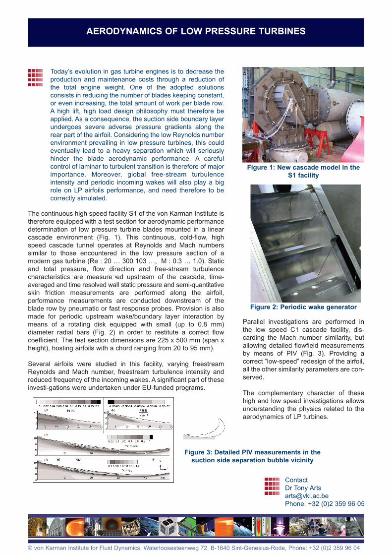
Figure 2: Periodic wake generator
Figure 3: Detailed PIV measurements in the
suction side separation bubble vicinity