AE 10 Airplane Design. Preliminary Aircraft Design Process 1. Mission Specification 2. Configuration...
44
AE 10 Airplane Design
-
Upload
ashley-bates -
Category
Documents
-
view
228 -
download
2
Transcript of AE 10 Airplane Design. Preliminary Aircraft Design Process 1. Mission Specification 2. Configuration...

AE 10Airplane Design

Preliminary Aircraft Design Process1. Mission Specification2. Configuration Design3. Weight Sizing4. Performance Sizing5. Fuselage Design6. Wing Design7. Empennage Design8. Landing Gear Design9. Weight & Balance Analysis10.Stability & Control Analysis11.Drag Polar Estimation12.Final Design
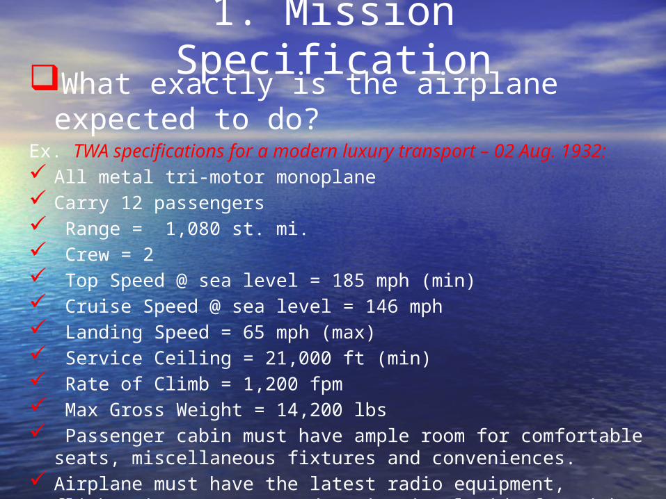
1. Mission SpecificationWhat exactly is the airplane expected
to do?Ex. TWA specifications for a modern luxury transport – 02 Aug.
1932: All metal tri-motor monoplane Carry 12 passengers Range = 1,080 st. mi. Crew = 2 Top Speed @ sea level = 185 mph (min) Cruise Speed @ sea level = 146 mph Landing Speed = 65 mph (max) Service Ceiling = 21,000 ft (min) Rate of Climb = 1,200 fpm Max Gross Weight = 14,200 lbs Passenger cabin must have ample room for comfortable seats,
miscellaneous fixtures and conveniences. Airplane must have the latest radio equipment, flights
instruments, and navigational aids for night flying
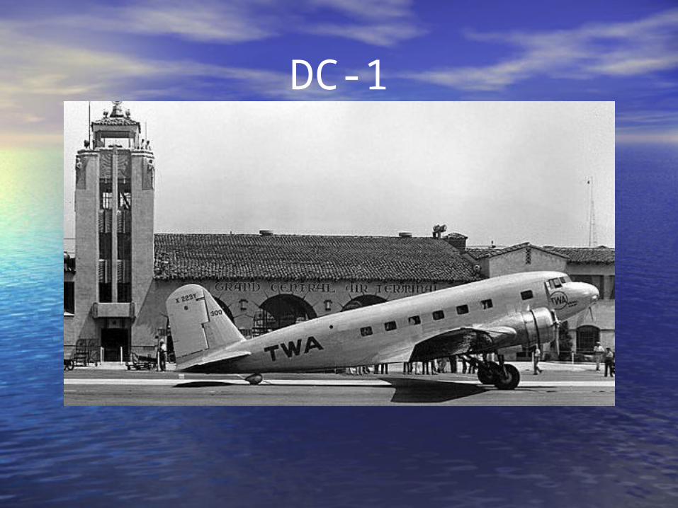
DC-1
Requirements are extremely important because they
Drive the design Are the yardstick by which the
success of the design is measured

Aircraft companies have lost large amounts of $$ because they followed a bad or inappropriate set of requirements:

Spruce Goose (Hercules), 1947Designed by Howard Hughes
700 passenger (cargo + troop carrier) 8 x 3,000 hp 8-cylinder engines: largest piston engines ever produced for an ac
Urgent government project in 1942, had lost all priority by 1944
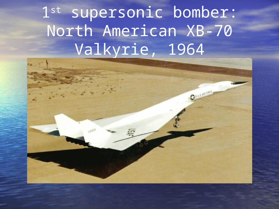
1st supersonic bomber: North American XB-70 Valkyrie, 1964

C-5 Galaxy, June 30, 1968LG Design, LG: 28 wheels, tires can be inflated / deflated in fight !

Length = 3 – 4 in.Weight = 0.25 oz.
Takeoff & Landing: VerticalSpeed = 60 mph
Range = 1 mileFlight Altitude: less than 1,000 ft
Heart Rate: 1,200 / min (20 / sec)Wing Beats: 70 - 200 / sec
Control: Very PreciseRefueling: In-flight
Consumes: 155,000 calories / day its own weight in fuel every 18 hrs
Visits 2,000 flowers / day to feed
To sustain same level of activity a human would have to eat
220 lbs of hamburger per day.

Trumpeter Swan takeoffLake Michigan

2. Configuration DesignRefers to the positioning of the major parts of the airplane Wing Fuselage Empennage Engines Landing gearin relation to each other.
What will the airplane look like?

An – 225 with Buran

2. Configuration Design Ideal configuration: the cg of WE, WF, WPL
are all at the same longitudinal location. Why?
– Limits cg travel.– Reduces Swet because there is less need for trim control
power. Think:
– Light– Simple– Accessibility– Maintainability– Cost

2. Configuration Design
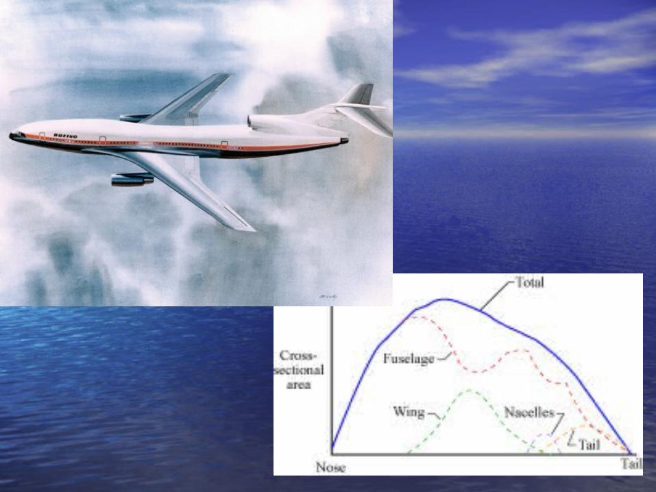
Minimize interference D. At high M<1 it may be necessary to apply
local area ruling to reduce Dwave (B-747)

2. Configuration Design For M>1 airplanes, area ruling at several M
is necessary. Ideal shape: Sears-Haack body of revolution

2. Configuration Design
Structural Synergism: major intersecting structural components should be arranged to avoid duplication of special heavy structure.

Piaggio P – 180 Avanti
Preliminary Sizing
Weight Sizing Performance Sizing

3. Weight Sizing
TOW or WTO is a very important design parameter; it sizes the entire vehicle– Wing size = f (WTO)
– Landing Gear size = f (WTO)
– Acquisition Cost = f (WTO)

y = 1.067x + 0.109
1.3
1.4
1.5
1.6
1.7
1.8
1.9
2
2.1
2.2
1.2 1.3 1.4 1.5 1.6 1.7 1.8 1.9
Log
(Tak
e-o
ff W
eigh
t, L
BS)
UAV Weight Trends
Log (Empty Weight, LBS)
Weight of Payload = 15 lb
Weight of Fuel = 25 lb
A = 1.067B = 0.109
Wto = 98.213 lb
WE = 58.197 lb
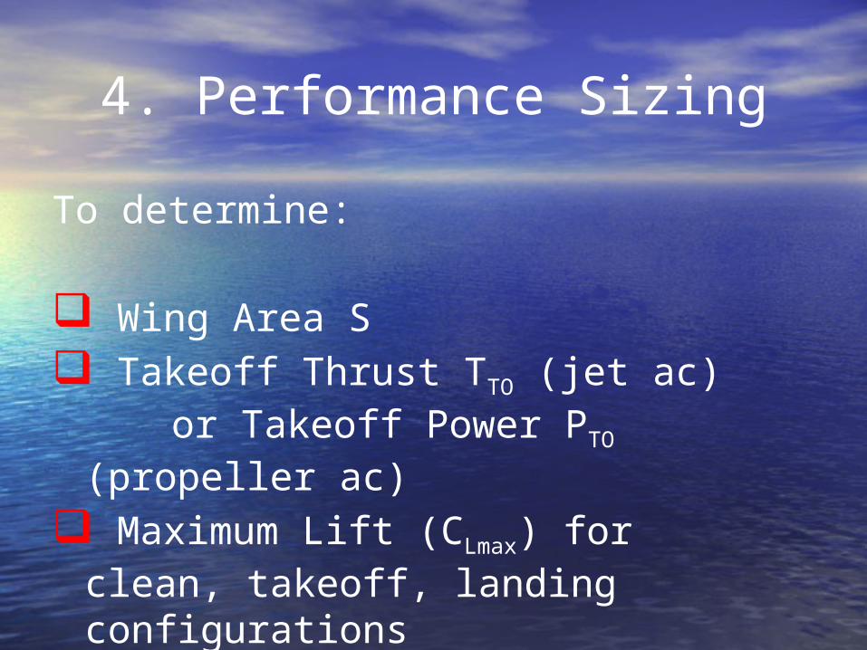
4. Performance Sizing
To determine:
Wing Area S Takeoff Thrust TTO (jet ac)
or Takeoff Power PTO (propeller ac)
Maximum Lift (CLmax) for clean, takeoff, landing configurations

Typical Performance Requirements Field length
– Takeoff dTO
– Landing dLND
Speed– Stall Vs
– Cruise Vcr
– Maximum Vmax

Typical Performance Requirements Climb
– Rate-of-climb (ROC) – AEO, OEI– Time-to-climb (TTC) to some altitude– ROCmin @ some altitude (operating
ceiling)– Balked landing– Climb Gradient (CGR)– Military Climb Requirements

Typical Performance Requirements Maneuvering
– Min turn rate (Y) – utility, agricultural, aerobatic, military ac
– Min turn radius– Specific Excess Power (Ps)
Airworthiness– Phoenix AZ 1990: airport closed for 3
days because of the heat; no civil ac could meet the takeoff field requirement


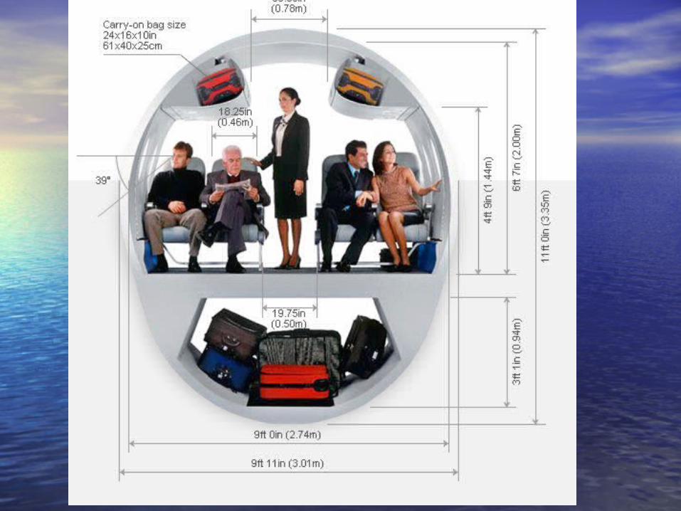
5. Fuselage Design

5. Cockpit Design
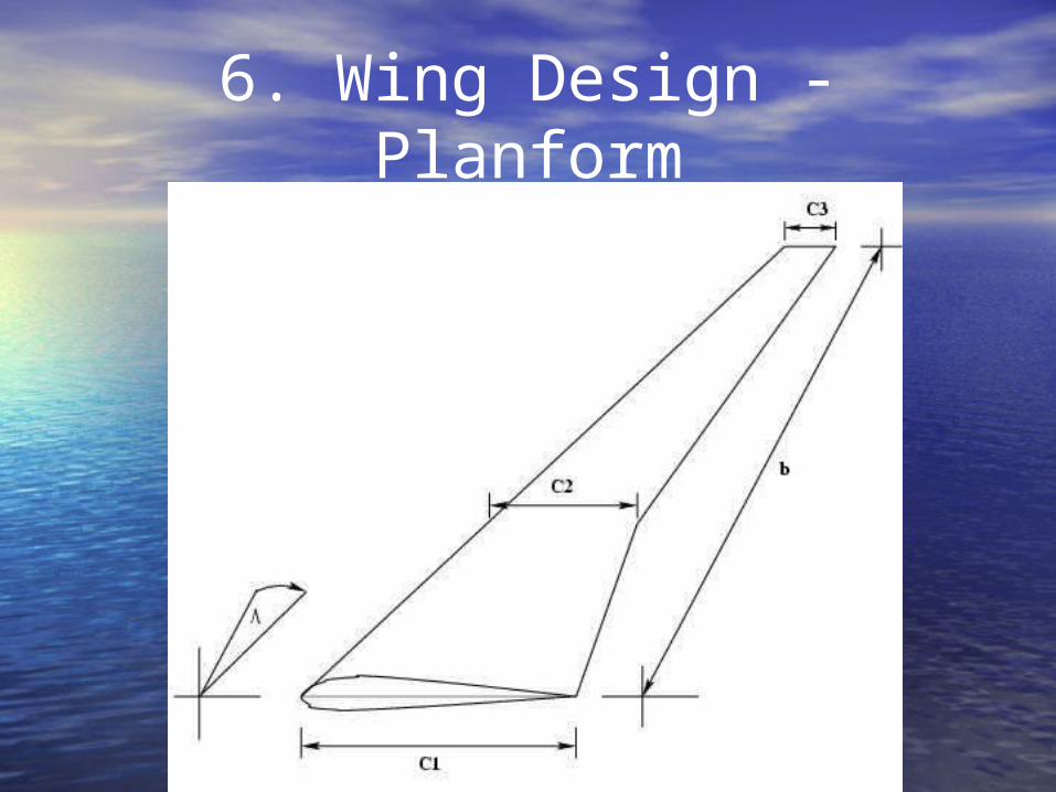
6. Wing Design - Planform

6. Wing Design - Airfoil

6. High-Lift Devices

6. Wing Design – lateral controls


7. Empennage Design


8. Landing Gear Design

9. Weight & Balance
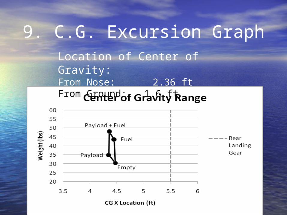
9. C.G. Excursion GraphLocation of Center of Gravity:From Nose: 2.36 ftFrom Ground: 1.6 ft

10. Longitudinal Static Stability
0 0.5 1 1.5 2 2.5 30
0.05
0.1
0.15
0.2
0.25
0.3
0.35
0.4
0.45
X position of aft center of gravity
X position of aerodynamic center
18% Static Margin Design Point
Horizontal Stabilizer Area (ft2)
Fra
ctio
n o
f M
ean
Aero
dyan
mic
Ch
ord
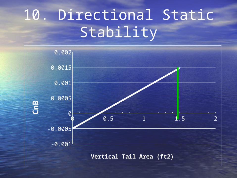
10. Directional Static Stability
0 0.5 1 1.5 2
-0.001
-0.0005
0
0.0005
0.001
0.0015
0.002
Vertical Tail Area (ft2)
Cn
B
0 0.2 0.4 0.6 0.8 1 1.2 1.4 1.60
0.02
0.04
0.06
0.08
0.1
0.12
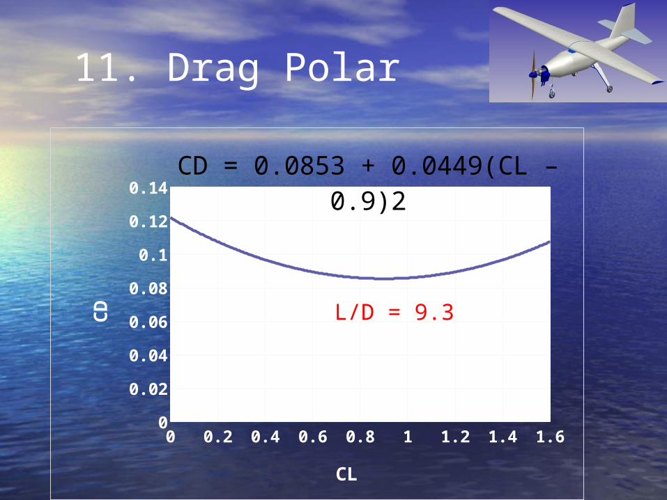
0.14CD = 0.0853 + 0.0449(CL –
0.9)2
CL
CD L/D = 9.3
11. Drag Polar

12. Final Design