Advanced WLAN tutorial - Politecnico di...
96
Advanced WLAN tutorial AST – E.Filippi March 05
Transcript of Advanced WLAN tutorial - Politecnico di...

Advanced WLAN tutorial
AST – E.FilippiMarch 05

General trends in wireless communications
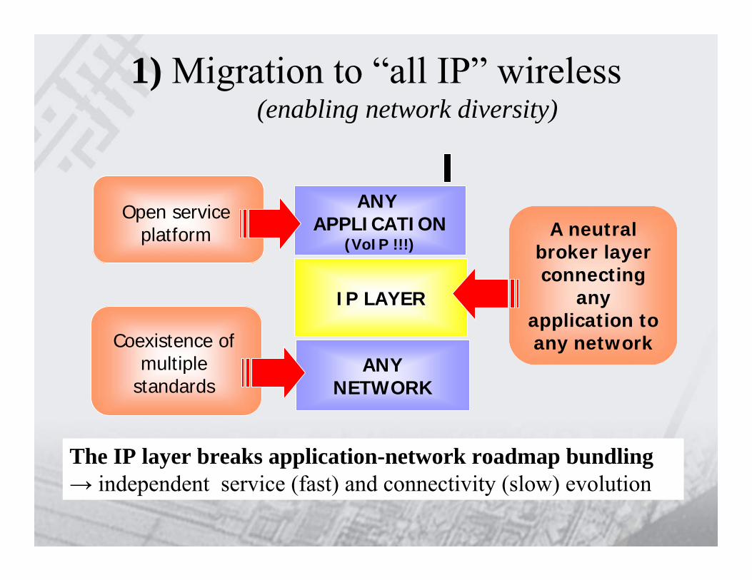
1) Migration to “all IP” wireless(enabling network diversity)
IP LAYERIP LAYER
ANYNETWORK
ANY APPLICATION
(VoIP !!!)A neutral
broker layerconnecting
any application to any network
Open service platform
Coexistence of multiple
standards
The IP layer breaks application-network roadmap bundling→ independent service (fast) and connectivity (slow) evolution

2) worldwide Spectrum Reform(enabling adaptive communication)
• Increase allocations for unlicensed use• Fewer restrictions on licensed spectrum• Exploration of “underlays” and “overlays”
– Spectrum Sharing techniques• Make rules and adoption more progressive
– From Usage Based to Policy Based rules• Harmonize Worldwide
RegulationsRegulations& Policy& Policy

3) Migration to OFDM++ systems(towards Gigabit data rates)
• Very efficient use of the available spectrum– Good for high data rates
• Very flexible use of the radio resource– Good for variable-bit rate data traffic
• Native broadcast– Good for content distribution

Wireless Standards
IEEE 802.15.3 UWB, Bluetooth
Wi-Media, BTSIG, MBOA
WAN (>10 km x cell, <10Mbps)
MAN (2-5 km x cell, ~10Mbps)
LAN (~100m x cell, ~100Mbps)
PAN (<10m x cell, ~100Mbps typ x user)
IEEE 802.11 Wi-Fi Alliance
IEEE 802.16d WiMAX
IEEE 802.20IEEE 802.16e
3GPP (GPRS/UMTS)3GPP2 (1X--/CDMA2000)
GSMA, OMA
SensorsIEEE 802.15.4(Zigbee Alliance)
RFID(AutoID Center)
IEE
E 8
02.2
1,IE
EE
802
.18
802.
19
RAN (>40 km x cell, <10Mpbs)IEEE 802.22

IEEE802.15 Wireless Personal Area Networks (WPAN) • UWB (Multi-band OFDM)
IEEE802.11 Wireless Local Area Networks (WLAN)• OFDM, MIMO-OFDM (multi-antenna OFDM)
IEEE802.16 Broadband Wireless Access (BWA)• OFDM, OFDMA
IEEE802.20 Mobile BWA• “flash” (coded) OFDMA
IEEE802.22 Wireless Regional Area Networks (WRAN)• “cognitive radio”
New wireless technologies incubated @ IEEE802.xx

----Inventory Control
------Sensor Networking
----Home Mesh
Neighbor-hood Mesh
Enterp/Home/N
Mesh Networking
-
-
-
-
-
-
-
RFID
-
-
-
-
-
UWB
-
-
-
-
-
3GPP/2
-
-
(audio streaming)
-
-
Bluetooth
Automotive
--Cable/device Replacement
--Wide Area Mobility
-Proprietary sol’n
Backhauling and last mile
--Home multiple A/V distribution
--LAN for Home
--LAN for Enterprise
Zigbee.16 WiMAX.11 Wi-FiTechnology
Potential application Scenarios

A deeper look to the 802.11 (Wi-Fi) family evolution

Wi-Fi Industry Status• Increased interest in cellular/Wi-Fi handsets. • Price gap for .11g and .11a/g is decreasing rapidly; .11b
only devices on steep decline• Voice over Wi-Fi becoming reality with technical
enhancements - WMM, .11i, .11k, .11r• Security solutions acceptable (WPA2, PEAPv2); security
deployment issues being addressed• Hotspot roaming agreements identified as critical to
carriers & ISPs• Standardization started for 100Mbps WLAN (802.11n)
with 2 strong proposals• Standardization started for automotive extensions
(802.11p)

Worldwide Wi-Fi Semiconductor Revenues by Application, 2003 - 2008 ($M)
0
500
1000
1500
2000
2500
3000
3500
2003 2004 2005 2006 2007 2008
Chip Inventory
AccessPoints/Gateways/BridgesMobile PC
Desktop PC
Consumer Devices
Mobile Devices
Printers/MFPs
Aftermarket USB
Aftermarket PCI
Aftermarket NIC
Source: IDC brief: Worldwide WLAN Semiconductor Forecast and Analysis, 2004 – 2008.

802.11 WLAN baseline Standard suite

2006 2007200520042003200220012000199919981997199619951994
Growing 802.11 Standard improvements
802.11802.1111a11a
11b11b11c11c
11d11d11e11e
11g11g11h11h
11i11i11j11j
11k11k11n11n
11f11f
11s,v,t,r,p11s,v,t,r,p
ST current Adv. R&D+ active Std
partic.

WLAN High Throughput extensions

802.11n – 100Mbps WiFi
• The “fast Ethernet” of WiFi– At least 100 Mbps “goodput” mandatory– Linear “obvious” point in any WLAN roadmap
• High scalability of the solution– PHY Data rate: from 54 up to 530 MBit/s– Tx, Rx antennas: from 1 to 4– channel bandwidth: 20 and 40 MHz– Backward-compatible with 802.11a/b/g
• Flexible throughput/reliability tradeoff possible– Diversity maximization ⇒ Space Time Codes (STC)– Data rate maximization ⇒ Spatial Division Multiplexing
• Very high spectral efficiency– Bit/s/Hz growing linearly with the number of antennas

802.11n Std Roadmap• Activity started in Q4 ‘02• Par/5 Criteria: March ’03• Functional Requirements: Nov ‘03• Usage Models: May ’04• Comparison Criteria: May ‘04• Proposals: Sept ’04• … convergence, plug fests, beta, …• Ratification: Sept ’06• Wi-Fi Certification: Sept ‘06

802.11n MIMO-OFDM technology
More bit/s/Hzand performances@ same total power
Robust vsmultipathSimplified equalization
Lower S/NHigher Code Rate
Higher system efficiency
MIMO OFDMAdvancedChannel Code(LDPC, TC)
E-MAC
spatial multiplexing + powerful outer code=
Tremendous capacity increase with the same total TX power

MIMO wireless comms

MIMO capacity• Channel impulse response matrix is
invertible– Provided sufficiently high dispersion in the
environment– Invertible => N parallel and independent spatial
channels exist• Capacity of the Space-Time MIMO channel
is much higher– Tremendous capacity increase with same total TX
power– Data communication possible even with negative
average SNRs per antenna

Is the 802.11 MAC sufficient for wireless high speed LANs?

802.11 Basics
• Fixed interframe spaces (IFSs)– aSlot, SIFS– All IFS others are sums of the above
• Multiple PHY modes– E.g. 802.11a, 802.11b, 802.11g– IFS constant for all PHY modes within same
standard• 802.11 relies here on
Basic calculations
• Simple scenario– One receiving station, one transmitting station
• Backoff duration equal toDIFS + 7.5*aSlot
• Error free wireless medium

PHY efficiency
• 802.11a• BPSK ½• Highly
efficient0
1
2
3
4
5
6
100 500 900 1300 1700 2100
Packet size (B)
Thro
ughp
ut (M
b/s)
0
0,2
0,4
0,6
0,8
1
Effic
ienc
y
w/o RTS/CTS with RTS/CTSEfficiency w/o RTS/CTS Efficiency with RTS/CTS

IFS limiting throughput
• OFDM PHY• IFS according
to 802.11a• Assuming
infinite PHY speed
0
20
40
60
80
100
120
100 500 900 1300 1700 2100
Packet size (B)
Thro
ughp
ut (M
b/s)
0
0,2
0,4
0,6
0,8
1
Effic
ienc
y
w/o RTS/CTS with RTS/CTSEfficiency w/o RTS/CTS Efficiency with RTS/CTS

Assuming new PHY• OFDM based• Preamble =
12µs• Header = 3µs• tSYM = 3µs• aSlot = 4µs• SIFS = 8µs• 1024Mb/s PHY
0
50
100
150
200
100 500 900 1300 1700 2100
Packet size (B)
Thro
ughp
ut (M
b/s)
0
0,2
0,4
0,6
0,8
1
Effic
ienc
y
w/o RTS/CTS with RTS/CTSEfficiency w/o RTS/CTS Efficiency with RTS/CTS

Performance problems
• Static overhead (e.g. OFDM)– Independent of PHY speed (IFS etc.)
• Protocol overhead– One ACK per one DATA frame
• 802.11e Block ACK very important to increase efficiency!
– Often transceiver turnaround• Duration limited by hardware
• Constant preamble duration (OFDM)– Can be become quite large compared to DATA

Design issues for future MAC
• Idle channel is unused capacity
• Develop collision free MAC
• Avoid signaling for channel competition
• Piggyback additional information
• Use all available information– Channel busy
histogram (11-03/340r1a)
– Listen to neighbors– QoS sensitive traffic
may be “predictable”– RTS but no CTS
reception enables parallel transmission

MAC design for high speed PHY
• Higher data rate →lower reception range
• Much bandwidth at high frequencies– High attenuation,
especially walls etc.
• Avoid small frames– Concatenate frames– Multiplex data
• Interference range determined by transmission power– Regardless of PHY
mode
• Incremental redundancy– Always highest PHY – Combine retransmitted
& failed frame

MAC regarding higher layers
• WLAN drawbacks on TCP– TCP transmission
window– MAC retransmissions
Terminate TCP at AP– Possible? Connection
tracking? How to replace TCP on wireless link?
• WLAN aware of applications?– VoIP
• Discard than retransmit– Concatenation of
frames

MAC regarding high attenuation
• Use attenuation to the benefit
• Spatial reuse possible
• Multi hop support needed– High speed
links with limited range

Conclusions
• 802.11 MAC worked very well– Highly efficient at low speed PHY– Drawbacks at high speed– Today’s “ethernet” (802.3) is switched
• WLAN is different
• Future WLAN will need new MAC– Support for multi hop, MAC routing– Increased efficiency– Avoid “legacy” backoff

What we can do for high throughput MAC
1.Reduce the overhead
2.Reduce the collisions
3.Optimize resources utilization
Reduce the overhead• Features from 802.11e
Packet bursting (TXop)Block-ACKDirect Link Protocol (DLP)
• Frame aggregation• Others
– E.g.: Turbo TCP / Piggybacking

802.11e WG recap• Formed in Dep. 1999. The first draft was available in 2001• Finalization expected for 2004.• Status: Letter ballot #67. Draft 8.0, opens 24th Feb, close
March 10th. Letter ballot #65, Draft 7.0 recirculation, from January 31st to February 15th 2004 (response ratio 94%, approve 93%)
• Scope: Enhance the 802.11 Medium Access Control (MAC) to improve and manage Quality of Service, and provide classes of service. Consider efficiency enhancements in the areas of the Distributed Coordination Function (DCF) and Point Coordination Function (PCF).
• Requirement: defining a new MAC backward compatible with the legacy MAC

What Does QoS Mean?
• Each application has a requirements tuple– max latency– min data rate– max packet drop probability
• The set of tuples define points that delimit the requirements curve
802.11e: 802.11e: QoSQoS SupportSupport

Why 802.11 does not guarantee QoS?
– DCF: Best-effort service with contention-based MAC
– PCF: • Inefficient and complex central polling scheme• Unpredictable beacon frame delay due to
incompatible cooperation between CP and CFP modes
• Transmission time of the polled stations is unknown
802.11e: 802.11e: QoSQoS SupportSupport

802.11 Distributed Coordination Function (DCF)
• Carrier Sense Multiple Access with Collision Avoidance (CSMA/CA)
802.11e: 802.11e: QoSQoS SupportSupport

DCFstop-and-wait ARQ
• Receiver of a directed frame returns an ACK
• If ACK not received, sender retransmits after another backoff
802.11e: 802.11e: QoSQoS SupportSupport

PCF• Poll-and-response MAC for nearly
Isochronous service• In infrastructure BSS only – Point
Coordinator (PC) resides in AP• Alternating Contention-Free Period (CFP)
and Contention Period (CP)
802.11e: 802.11e: QoSQoS SupportSupport
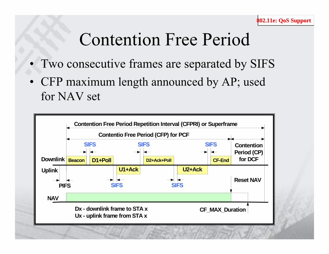
Contention Free Period• Two consecutive frames are separated by SIFS• CFP maximum length announced by AP; used
for NAV set
Beacon D1+Poll
NAV
SIFS
SIFS
U1+AckD2+Ack+Poll
SIFS
U2+Ack
SIFS
SIFS
CF-End
Uplink
Downlink
Contentio Free Period (CFP) for PCF
ContentionPeriod (CP)
for DCF
Contention Free Period Repetition Interval (CFPRI) or Superframe
Reset NAV
CF_MAX_DurationDx - downlink frame to STA xUx - uplink frame from STA x
PIFS
802.11e: 802.11e: QoSQoS SupportSupport

802.11e: QoS Improvements
802.11e MAC – Hybrid Coordination Function (HCF) with two access mechanisms– Contention-based channel access (Variation of legacy DCF )
• Enhanced Distributed Channel Access (EDCA) for prioritized QoS• Distributed Admission Control
– Controlled channel access (CCA) (Variation of legacy PCF)• Polling mode plus HC’s prioritized channel access for parameterized• Centralized Admission Control
802.11e: 802.11e: QoSQoS SupportSupport

QoS level in 802.11e
noneDCF, PCFLevel 0
prioritizedHCF (EDCF only)Level 1
Parameterized/prioritized
HCF (EDCF and HCF controlled channel access)Level 2
Scheduling policyChannel Access MechanismQoS Level
802.11e: 802.11e: QoSQoS SupportSupport

802.11e EDCA• Access category (AC)
as a virtual DCF• 4 ACs implemented
within a QSTA to support 8 priorities
• Multiple ACs contend independently for TxOp
• The winning AC transmits one or more frame (depends on TxOp value)
AC0 AC1 AC2 AC3
Virtual Collision Handler
Transmission Opportunity TXOP[AC]
backoffAIFS[0]CW[0]
backoffAIFS[1]CW[2]
backoffAIFS[2]CW[2]
backoffAIFS[3]CW[3]
backoffDIFS15
Transmit one Frame
Legacy
802.11e: 802.11e: QoSQoS SupportSupport

Differentiated Channel Access of 802.11e EDCA
• Each AC contends with – AIFS[AC] (instead of DIFS) and CWmin[AC] /
CWmax[AC] (instead of CWmin / CWmax)
802.11e: 802.11e: QoSQoS SupportSupport

Access Category
ACI: access category index
802.11e: 802.11e: QoSQoS SupportSupport

802.11e: Throughput enhancements
• Continuation of TxOp
• Block Acknowledgement
• Direct Link Protocol
• No-ACK
802.11e: Efficiency enhancements802.11e: Efficiency enhancements

Direct Link Protocol
• 802.11-1997 specification permits traffic in an AP-based network between clients and AP only
• 802.11e adds capability for clients to send traffic directly to each other– improves bandwidth efficiency, particularly in
home networks
802.11e: Efficiency enhancements802.11e: Efficiency enhancements

Direct Link Protocol
AP
StationStation
802.11e: Efficiency enhancements802.11e: Efficiency enhancements

Block Ack
• The Block Acknowledgement (Block Ack) mechanism allows a block of QoS Data MPDUs to be transmitted, each separated by a SIFS period, between two QSTAs.
• A cumulative ACK is sent at the end of the burst transmission
802.11e: Efficiency enhancements802.11e: Efficiency enhancements

Block Acknowledgmentack policy
• Immediate– Suitable for high-bandwidth, low latency traffic.
• Delayed– Suitable for applications that can tolerate
moderate latency.– Allow the existing implementations to use this
feature with minimal hardware changes and also to allow inexpensive implementations that would use the processing power on the host
802.11e: Efficiency enhancements802.11e: Efficiency enhancements

Block Acknowledgment
802.11e: Efficiency enhancements802.11e: Efficiency enhancements

Block AcknowledgmentProtection mechanism
• Collisions can cause many losses• RTS/CTS used to protect a burst

Block AcknowledgmentProtection mechanism
• RTS/CTS used to protect a burst• Response for the first frame to set NAV
RTS ……
RTS
RTS RTS
CTS CTS
DATA BURST
DATA BURST
……
ACK
DATA BURST
DATA BURST
ACK
NAV
NAV
NAV
NAV
Could be used to tx feedback information from the receiver

Frame Size Affects Throughput• 802.11 MAC/PHY have big fixed
overheads– MAC header, IFSs, ACK, and Backoff– PLCP preamble & headers
Busy Channel
DIFS34
usec PPDU ACK
PLCPPreamble
PLCP Header
Payload FCS
16 usec >= 4 usec 24 octets Variable 4 octets
SIFS (16 usec)
Backoff - 9 usec x [0,CW] >= 24 usec
MAC Header
802.11e: Efficiency enhancements802.11e: Efficiency enhancements

Frame Aggregation
1
1
221
Queue
2 2
1
3 PPDUscreated
t
1
1
221
Queue
2 2
12 PPDUscreated
t
.
Preamble + PLCP header
MAC headerFCS
Pad Bits + Tail
MPDU/PSDU
PPDU
1
Dest.
MSDU
IFS
1 2 2 3
1223
Queue
MPDU Agg. (1) MPDU Agg. (2)
PPDU Agg.

Further enhancements: optimize resources utilization
• Finer/tighter cross-layer interactionLink quality/Congestion estimation Extended MAC-PHY interface
• Link adaptation
802.11n ST MAC Proposal

Rate adaptation• There are two approaches for solutions to the
rate adaptation schemes:
– Auto Rate Fallback (ARF) - Use history of previous transmissions to adaptively select future rates
No changes to the protocols and standardsThey have to be carefully designed to achieve good performance
– Receiver-based auto rate (RBAR) - use signal measurements for rate selection
They achieve good performancebig overhead and changes to the Standard

Rate Rate adaptationadaptation• All the proposed schemes use static or near-static
thresholds:– WaveLAN (-2, +10)– IBM (-1, +10/+3) – it is a bit more dynamic than WaveLAN
because it is using two thresholds to account for different spread dopplers
• Further improvement: dynamically adapt the thresholds– 20-30% goodput improvement possible

WLAN mesh extensions
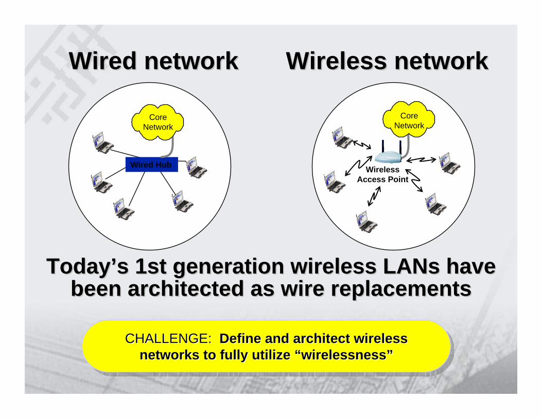
Core Network
Wireless Access Point
TodayToday’’s 1st generation wireless LANs have s 1st generation wireless LANs have been architected as wire replacementsbeen architected as wire replacements
Wired networkWired network Wireless networkWireless network
Wired Hub
Core Network
CHALLENGE: Define and architect wireless networks to fully utilize “wirelessness”
CHALLENGE: CHALLENGE: Define and architect wireless Define and architect wireless networks to fully utilize networks to fully utilize ““wirelessnesswirelessness””

Radio Networks• Current Radios optimize point to point RF link
performance• Radio Networks optimize total performance of the
network– Self-configuring mesh topology– Multi-hop Core
Network
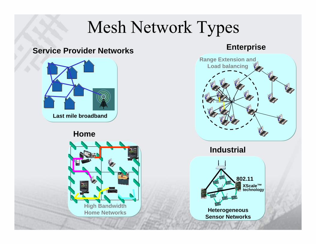
Mesh Network Types
Last mile broadband
HeterogeneousSensor Networks
802.11XScale™technology
Range Extension and Load balancing
High BandwidthHome Networks
EnterpriseService Provider Networks
Home
Industrial

IEEE 802.11s –PAR
• To develop an IEEE 802.11 Extended Service Set (ESS) Mesh with an IEEE 802.11 Wireless Distribution System (WDS) using the IEEE 802.11 MAC/PHY layers that supports both broadcast/multicast andunicast delivery over self-configuring multi-hop topologies.
• To extend the IEEE 802.11 MAC. No physical layer is included.• To provide a protocol for auto-configuring paths between APs over self-
configuring multi-hop topologies in a WDS to support both broadcast/multicast and unicast traffic in an ESS Mesh using the four-address frame format or an extension.
• A target configuration is up to 32 devices participating as AP forwarders in the ESS Mesh.
• To utilize IEEE 802.11i security mechanisms, or an extension thereof, for the purpose of securing an ESS Mesh.
• 802.11s Project Authorization Request (PAR) = Doc #11-04-54r2

802.11s – Example of .11s Mesh Network
N_MeshPoint
N_MeshPoint
N_MeshPoint
Mesh Portal
Mesh Portal
Mesh AP
Mesh AP
STA STA STA STA STA
InternetInternet
Mesh Network
BSSBSS
N_Mesh Point: Mesh Point without AP function or portal function

802.11s –Functional Requirements and Scope (1)
• Mesh Topology Learning, Routing and Forwarding• Mesh Security• Mesh Measurement• Mesh Discovery and Association• Mesh Medium Access Coordination• Compatibility to 802.11 Service• Interworking• Mesh Configuration and Management

802.11s –Functional Requirements and Scope(2)
802.11 ServiceIntegration Mesh RF Resource Ctrl & Management
Mesh Security
Mesh Routing&
Forwarding
Mesh Medium AccessCoordination
&Flow Control
Auto Discovery &Topology Learning
Mesh InterworkingMesh
Measurement
• High-level view on the system functions interactions

802.11s—Functional Requirements and Scope (3)
Mesh Topology Learning, Routing and Forwarding :• Possible Routing Protocol
– On-demand routing/proactive routing.– Topology-based protocol/distance-vector based protocol.– Uniform protocol/non-uniform protocol.
• Architecture to support alternative routing protocols• Mesh routing in the presence of low-power mesh points• Mesh routing with Multiple radio devices• Broadcast/multicast/unicast data delivery support

802.11s—Functional Requirements and Scope (4)
Mesh Security :• Secure association of Mesh Point• Secure data message/management message/routing
message• Centralized/distributed authentication and key
management• Extension of 802.11i for mesh

802.11s—Functional Requirements and Scope (5)
Mesh Measurement :• Specification of radio-aware metrics for use by mesh network• Mesh link/path quality measurements• Measurement to support channel selection• Measurement to aid STAs in making roaming decisionMesh Discovery and Association :• Protocols to allow Mesh Points to discover Mesh Networks• Protocols to allow Mesh Points to associate with a Mesh
Network• Protocols to allow Mesh Points to associate with other Mesh
Points within a Mesh Network

802.11s—Functional Requirements and Scope (6)
Mesh Medium Access Coordination :• Mitigate performance degradation caused by hidden
nodes/exposed nodes• Support of admission control• Support of congestion control• Improve spatial reuse• Management of multiple classes of traffic• Coordinating channel access across multiple nodes to avoid
performance degradation• Mesh link communication coordination

802.11s—Functional Requirements and Scope (7)
Compatibility to 802.11Services :• Mesh Point DS Services integration• Mesh compatibility with STA mobility/roaming• Techniques to meet 802.11r system requirementInterworking :• Interface with high level protocol• Interface with other IEEE 802 LANsMesh Configuration and Management :• Support for managed network management model• Support for unmanaged network management model• Self-configuration support• Information exchange about Capability information of Mesh Points• Mesh network channel selection• Support for time synchronization

802.11s –Usage Models (Potential Markets) 1
• Residential.– Indoor environment.– Mesh point number: 8.– Easy Installation.– Coexistence with other Mesh networks/BSSs.
• Office.– Indoor environment.– Mesh point number: 32.– Higher device density and bandwidth requirements as compared with
campus networks.– Support unmanaged mode and central managed mode.
• Campus/Community/Public Access Network. – Seamless connectivity over large geographic areas.– Mesh point number: 32-100.– Provide alternatives to traditional internet access methods.– Centralized management.– Scalability, automatic reconfiguration and reliability.
802.11s –Usage Models (Potential Markets) 2
• Public Safety– Semi-permanent infrastructure and Mobile mesh points coexist.– Mesh point number: 32.– Mostly outdoors.– Node mobility.– Dynamic variations in radio propagations.– Strong requirements of network self-configuration and self-management.
• Military.– Sensitive to energy conservation.– Mesh point number: 32.– Mostly outdoors.– Node mobility.– STAs need to become mesh AP temporarily.

802.11s – Major Deadlines• Those wishing to submit a proposal must send the 802.11
TGS Chair a notice of intent to submit at the end of the Friday before the March 2005 Meeting.
• 11s will allocate some time for the voluntary preliminary presentation of proposals at the March and May 802.11 Meetings.
• An IEEE 802.11 submission or submissions describing the proposal in detail must be uploaded to the 802wirelessworld server by midnight Eastern USA time, at the end of 15 June 2005.
• All the proposals will be presented at the July 2005 meeting of 802.11.

Is the 802.11 MAC sufficient for wireless mesh?
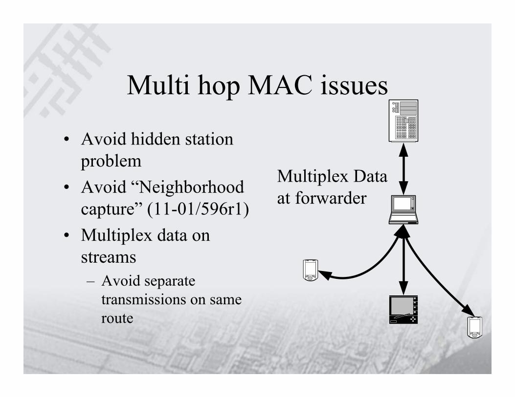
Multi hop MAC issues
• Avoid hidden station problem
• Avoid “Neighborhood capture” (11-01/596r1)
• Multiplex data on streams– Avoid separate
transmissions on same route
Multiplex Data at forwarder

Layer 3 RoutingISO/OSI: Network LayerInternet: IPWired WirelessBGP DSDV (proactiv)OSPF AODV (reactiv)etc. TORA (pro-/reactiv)
Layer 2 Medium accessISO/OSI: Data Link LayerInternet: MACWired WirelessCSMA/CD, CSMA/CAFull-Duplex Half-Duplex(switching) (collision)
Layer 1 Data CircuitISO/OSI: Physical LayerInternet: PHYWired WirelessTwisted Pair DSSSFibre Link FHSSCoax cable OFDM
Multi hop needs routing
• No information exchange between layers
• MAC layer routing instead L3 routing
• New routing aware of– PHY mode– Transmission power– Interference level, etc.

ST/UCLA Partial Proposal
• Routing Protocol• Congestion Control• Neighbor-list LC-EDCA• Admission Control

Routing Protocol Architecture
• Routing architecture allows proactive link state protocol and on-demand distance vector protocol to adapt to different usage scenarios.
– On-demand distance vector is the default routing protocol, it also used for large mesh networks. AODV (Ad hoc On Demand Distance Vector) is the distance vector protocol being selected.
– link state protocol is the option protocol, it is used for dense, high mobile network. OLSR (Optimized Link State Routing)+FSR (Fish Eye State Routing) is the link state protocol being selected.
• Routing architecture allows different routing destinations:– Routing to non-AP STAs is the default one.– Routing to Mesh Points is the optional one.
• Routing architecture allows different multicast routing protocol to adapt to different usage scenarios:
– Multicast Ad-hoc On Demand Distance Vector (MAODV) is the default routing protocol.
– ODMRP+MPR (On Demand Multicast Routing Protocol + Multiple PointReply) is the optional routing protocol.

Unicast Routing Protocol----AODV• AODV (Ad hoc On Demand Distance
Vector) is an on-demand distance vector protocol.– Route Request (RREQ) and Route Reply
(RREP) are used for finding a route from source to destination when the source has packets to send.
– It is a loop-free routing protocol. – RREQ is a broadcast packet and RREP is a
unicast packet.
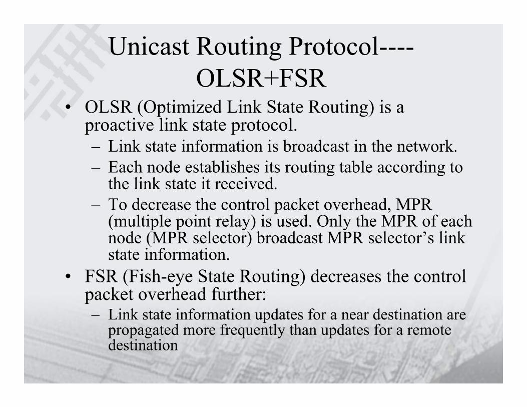
Unicast Routing Protocol----OLSR+FSR
• OLSR (Optimized Link State Routing) is a proactive link state protocol.– Link state information is broadcast in the network.– Each node establishes its routing table according to
the link state it received.– To decrease the control packet overhead, MPR
(multiple point relay) is used. Only the MPR of each node (MPR selector) broadcast MPR selector’s link state information.
• FSR (Fish-eye State Routing) decreases the control packet overhead further:– Link state information updates for a near destination are
propagated more frequently than updates for a remote destination

Routing To Non-AP STA• Each non-AP STA is the routing destination.• The mesh AP is the routing proxy of its associated non-AP STA.• The routing table includes non-AP STAs and mesh points as the
destinations of the routes• 4 MAC addresses in the 802.11 header are enough to route the packet
Mesh Point2
Mesh Point1
Mesh Point3
Mesh Portal1
Mesh Portal2
Mesh AP1
Mesh AP2
STA1 STA2 STA3 STA4 STA5
Internet
Mesh Network
BSSBSS
Mesh Point3’s routing table:Destination : Next HopSTA4 : Mesh AP2STA3 : Mesh AP2STA1 : Mesh Point2Mesh Portal2: Mesh Portal2Mesh Portal1: Mesh Point2
Mesh AP2’s routing table:Destination : Next HopSTA1 : Mesh Point1STA2 : Mesh Point1Mesh Portal2: Mesh Point3Mesh Portal1: Mesh Point1

Routing To Non-AP STA• Data Packet Forwarding
– The source mesh point does the following functions: • Add 11s’ header• Fill the frame type and TTL• Look up the routing table to find the next hop mesh
point, and send the packet out to the next hop– The destination mesh point does the following functions:
• Delete 11s’ header

Routing To Mesh Point• Only the Mesh Point is the routing destination.• The mesh AP broadcasts its associated non-AP STAs to the border mesh
points which include mesh portals and mesh APs.• The routing table includes mesh points as the destination of the routes• A special map table which maps the non-AP STAs to the associated mesh AP is
defined in each border mesh point.• 6 MAC addresses are required to route the packet.
Mesh Point2
Mesh Point1
Mesh Point3
Mesh Portal1
Mesh Portal2
Mesh AP1
Mesh AP2STA1
STA2
STA3 STA4 STA5
Internet Mesh Network
BSS
BSS
Mesh Point3’s routing table:Destination : Next HopMesh AP2 : Mesh AP2Mesh AP1 : Mesh Point2Mesh Portal2: Mesh Portal2Mesh Portal1: Mesh Point2
Mesh AP2’s routing table:Destination : Next HopMesh AP1 : Mesh Point1Mesh Portal2: Mesh Point3Mesh Portal1: Mesh Point1
Mesh AP2’s Map table:Non-AP STA : Mesh APSTA1 : Mesh AP1STA2 : Mesh AP1

Routing To Mesh Point• Data Packet Forwarding
– The source mesh point does the following functions: • Add 11s’ header• Fill the frame type and TTL• Set the Destination STA MAC ADDR according to 802.11’s DA • Set the Source STA MAC ADDR according to 802.11’s SA • Set the 802.11’s SA according to the source mesh point’s MAC address• Look up non-AP STA map table to find the destination mesh point of
the destination STA, set the 802.11’s DA according to the destination mesh point’s MAC address
• Look up the routing table to find the next hop mesh point, and send the packet to the next hop
– The destination mesh point does the following functions:• Set the 802.11’s DA according to the Destination STA MAC ADDR• Set the 802.11’s SA according to the Source STA MAC ADDR• Delete 11s’ header
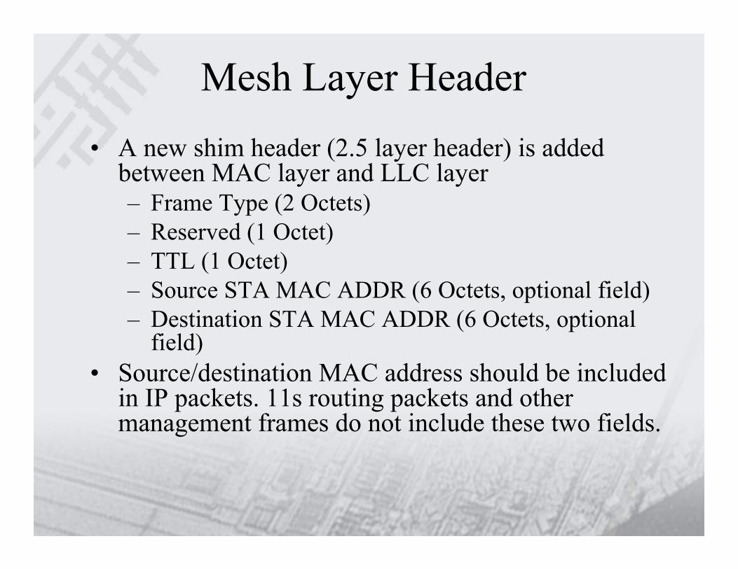
Mesh Layer Header• A new shim header (2.5 layer header) is added
between MAC layer and LLC layer– Frame Type (2 Octets)– Reserved (1 Octet)– TTL (1 Octet)– Source STA MAC ADDR (6 Octets, optional field)– Destination STA MAC ADDR (6 Octets, optional
field)• Source/destination MAC address should be included
in IP packets. 11s routing packets and other management frames do not include these two fields.

Multicast Routing----Tree-based Multicast Routing Protocol
• A tree is built for group communication.• Only one path exists between any two multicast
members.• A multicast group leader maintains up to date
multicast tree information by sending periodic hello information.
• It scales well for the sender number and multicast group number.
• In fast mobile network, the packet delivery ratio becomes worse.

Multicast Routing----Tree-based Multicast Routing Protocol
• MAODV (multicast Ad-hoc On-Demand Distance Vector) is a tree-based multicast routing protocol.
• A mobile node wishing to join a multicast group or having data to send to a multicast group originates a Route Request (RREQ).
• After receiving a RREQ, the intermediate node rebroadcasts RREQ and establish the reverse route if it is not the multicast group’s member.
• If the multicast group’s member receives a RREQ, it unicast a Route Reply (RREP).
• As the nodes along the path to the source node receive the RREP, they add both a route table entry and multicast route table entry for the node.
• The source node activates the multicast route to it through unicasting a multicast activation (MACT).

Multicast Routing----Mesh-based Multicast Routing Protocol
• A mesh forwarding path is built for group communication.
• More than one path may exist between multicast sender and multicast receiver pair.
• Every source node will periodically send out route request through the network.
• It scales well for the sender number and multicast group number.
• The mesh-based multicast is more robust since alternative path exists.

Multicast Routing----Mesh-based Multicast Routing Protocol
• ODMRP (On-Demand Multicast Routing Protocol) is a mesh-based multicast routing protocol.
• While a multicast source has packets to send, it flood a JOIN QUERY with data piggybacked.
• When a node receives a non-duplicate JOIN QUERY, it stores the upstream node ID into the route table and rebroadcast the packet.
• When the JOIN QUERY packet reaches a multicast receiver, the receiver creates and broadcast a JOIN REPLY to its neighbors.
• When a node receives a JOIN REPLY and it is on the path to the source, it sets forwarding group flag and broadcasts its own JOIN REPLY until it reaches the multicast source.

Multicast Routing----ODMRP+MPR• If OLSR is used as the unicast ad hoc network
routing protocol, MPR is selected by each node.• Only MPR of a node rebroadcast JOIN QUERY.• This can decrease control packet overhead. • ODMRP+MPR has the following features:
– The proposed multicast routing protocol is more robust in mobile environment.
– The proposed multicast routing protocol is more scalable to large multicast group.
– MPR feature can only be activated if OLSR routing protocol is used as unicast routing protocol.

Congestion Control (1)Actual Scheduling Result when load=700kb/s
674k 449k 355k 235k
238k 347k 450k 697kRx: 238k 1021k 899k 1052k 235kTx: 674k 687k 702k 685k 697k
e2e throughput
430k 430k 430k 430k
430k 430k 430k 430kRx: 430k 860k 860k 860k 860kTx: 430k 860k 860k 860k 430k
e2e throughput
Ideal Scheduling, when the network is overloaded
Congested nodes
Wasted TX

Congestion Control (2)• .11e Access Category-based congestion control• Each MP detects network congestion according to:
– Delay.– Queue size.– Packet loss rate.
• When congestion occurs, random early congestion notification information is sent to the upstream MP.
• The upstream MP polices the packet transmission rate.

Congestion Control (3) • Congestion control simulation result
•Shadowing channel model in NS2 is used in the simulation.
•TXOP is enabled: TXOP[AC:0] = 3008; TXOP[AC:1] = 3008; TXOP[AC:2] = 3008; TXOP[AC:3] = 1504.
•Simulation scenario is:
PHY rate 54 MbpsUDP 1 30 MbpsUDP 2 30 MbpsBlock Ack disabled
1 2UDP 1
UDP 20UDP 1
UDP 23
UDP 1
UDP 2
0, 0 100, 0 200, 0 300, 0
0
1000
2000
3000
4000
5000
6000
TXOP CGT_CTL
Agg
rega
ted
Goo
dput
(kbp
s)
CGT_CTL: Congestion Control
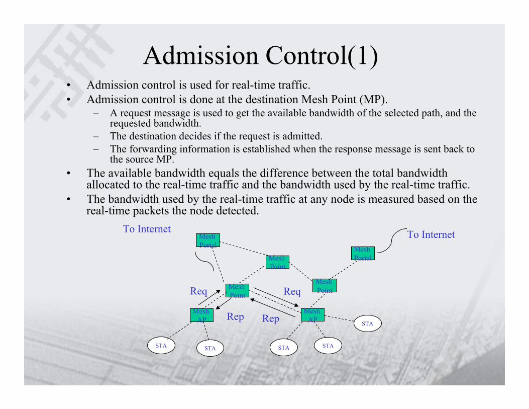
Admission Control(1)• Admission control is used for real-time traffic.• Admission control is done at the destination Mesh Point (MP).
– A request message is used to get the available bandwidth of the selected path, and the requested bandwidth.
– The destination decides if the request is admitted.– The forwarding information is established when the response message is sent back to
the source MP.• The available bandwidth equals the difference between the total bandwidth
allocated to the real-time traffic and the bandwidth used by the real-time traffic.• The bandwidth used by the real-time traffic at any node is measured based on the
real-time packets the node detected.
To InternetTo Internet
Mesh Point
Mesh Point
Mesh Point
Mesh Portal Mesh
Portal
Mesh AP
Mesh AP
STA STA STA STA
STA
Req Req
RepRep

Admission Control(2)• The reasons for re-admission control.
– Node mobility– False admission.
• The congested MP randomly selects some admitted traffic and notifies the source MP to request admission again.
Mesh Point2
Mesh Point1
Mesh Point3
Mesh Portal1
Mesh Portal2
Mesh AP1
Mesh AP2
STA STA STA STA
STA
To InternetTo Internet
Req(1) Req(2)
Rep(5)Rep(7) Req(3)
Req(4)Rep(6)
Rep(8)
The available bw of MP1: 5MbpsThe available bws of other MPs: 10MbpsThe bw requested by MAP1:3MbpsThe bw requested by MAP2: 4Mbps
MAP2’s request is granted!
MAP1’s request is granted!