Advanced cooling system for heavy vehicles-03-31 … cooling system for heavy vehicles – heat...
24
Advanced cooling system for heavy vehicles – heat exchangers/coolers Wamei Lin
Transcript of Advanced cooling system for heavy vehicles-03-31 … cooling system for heavy vehicles – heat...

Advanced cooling system for heavy vehicles –
heat exchangers/coolers
Wamei Lin

Outline
Introduction of my projectEnergy distribution in vehicleMethods for saving energyNew material for heat exchangersConclusion of graphite foam heat
exchangerFuture work
Introduction of my project
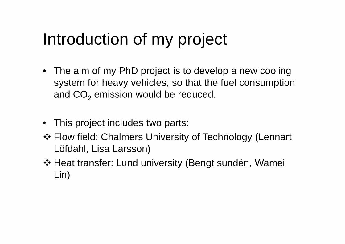
• The aim of my PhD project is to develop a new cooling system for heavy vehicles, so that the fuel consumption and CO2 emission would be reduced.
• This project includes two parts: Flow field: Chalmers University of Technology (Lennart
Löfdahl, Lisa Larsson) Heat transfer: Lund university (Bengt sundén, Wamei
Lin)

Energy distribution in vehicle In order to save fuel
consumption in vehicles, what can be done?
(1)Can we reuse some energy from the engine coolant?
(2)Can we recover some energy from the exhaust gas?
(3)Can we recover some mechanical energy?

Engine cooling
• Radiator: to make sure the engine works at its optimal temperature (80-90°C).
• Intercooler: to cool down the fresh air, whose temperature is increased after through a turbocharger.

Methods for saving energyEngine cooling: thermal management
14.5 kW power was saved in a standard diesel vehicle (Cho
2007)

Methods for saving energyExhaust gas (vary between 250 and 680 )
(1) Heating compartment
(2) Absorption cooling:7.1 billion gallons of gasoline was saved in U.S. vehicles (2002 Johnson)
(3) Thermoelectric device:Peltier-Seebeck effect.3-8% of fuel consumption can be saved (2007 Smith)

Methods for saving energy
During the braking process, we can store the mechanical energy and use it to drive vehicle later.(1)Transfer the mechanical energy into electricity(2)During the braking process, the kinetic energy is used to generate a high pressure gas, which is used to drive vehicles later.
80% of kinetic energy lost in the braking process can be recovered
The mechanical work
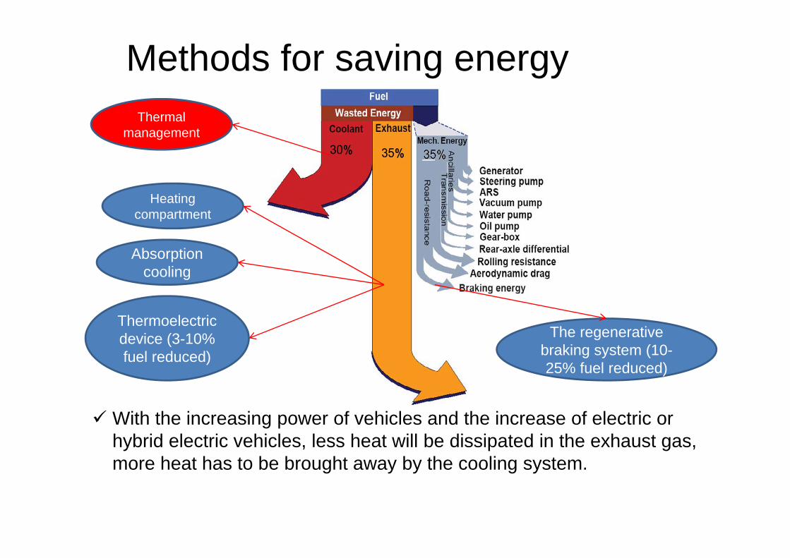
With the increasing power of vehicles and the increase of electric or hybrid electric vehicles, less heat will be dissipated in the exhaust gas, more heat has to be brought away by the cooling system.
Heating compartment
Absorption cooling
Thermoelectric device (3-10% fuel reduced)
Thermal management
Methods for saving energy
The regenerative braking system (10-25% fuel reduced)

New material for heat exchangers
The thermal management development
Aluminum and copper heat exchanger(180 W/(m.K) for aluminum
6061 and 400 W/(m.K) for copper)
The utilization of microcellular foam materials such as metal or graphite foams(the enhancement of heat transfer by huge fluid-solid contact surface area and the fluid mixing)
Cooling power increasing

Graphite foam
New material for heat exchangers
An appropriate material for the thermal
management
High thermal conductivity: (Ksolid=1700
W/(m.K). Keff=150W/(m.K) >
Keff.Al=2-26W/(m.K))
Low density: 0.2-0.6g/cm3, 20% of that of
Aluminum Large specific surface area:
5000-50000m2/m3

New material for heat exchangers Problems
• The high pressure drop The effective area of heat transfer is reduced; A large input of pumping power, a low coefficiency of performance.
• Weak mechanical properties The tensile strength of graphite foam with porosity of 75 % is only
0.69 MPa. However, the tensile strength of nickel foam with the same porosity is 18.44 Mpa.
• The dust blocking

New material for heat exchangers• In order to reduce the pressure drop of graphite foams, four different
configurations of foams (pin-finned, blind-holes, corrugated and baffle) are analyzed.
Graphitefoam
Porosity (ε) Porediameter(Dp) (um)
Specificsurfacearea(β)(m2/m3)
Effectivethermalconductivity(keff)(W/m.K)
Permeability(α) (m2)
Forchheimercoefficient(CF)
POCO 0.82 500 5240 120 6.13x10⁻¹⁰ 0.4457

Verification of the simulation model
• The pressure drop values of the present simulation model are justified to be comparable to experiment.
• The Nusselt numbers of the present simulation model are slightly higher than the experimental results.
0
5
10
15
0 0.02 0.04 0.06 0.08 0.1
Frontal velocity (m/s)
Pres
sure
dro
p (k
Pa)
Experiment [6]
Simulation 020406080
100120140160
0 0.02 0.04 0.06 0.08 0.1Frontal velocity (m/s)
Nus
selt
num
ber N
u
Experiment [6]
Simulation

Pressure drop of graphite foam• The pressure loss through
the graphite foam is based on the Forchheimer extended Darcy equation
f f Fi i i
CdP u u udx
• The corrugated and pin-finned foams have lower pressure drop, due to the short flow length (corrugated) and smooth flow path (pin-finned).
• The configuration has important effect on the pressure drop of foams.
15 times
Frontal air velocity (m/s)
0
50
100
150
200
250
300
350
400
0.1 0.2 0.3 0.4 0.5 0.6 0.7 0.8 0.9 1
Pres
sure
dro
p (P
a)
corrugated
blind-holes
bafflepin-f inned

Thermal performance of graphite foam
• Nusselt number (Nu) is calculated by
N p h removed
f f b base inlet
h D D Quk k A T
• Due to the low flow resistance through the corrugated and the pin-finned foams, more cold air can reach the surface inside the foam and bring away the heat from the foam. Thus, the effective heat transfer
surface is larger in the corrugated and the pin-finned foams
removedQ . .effh A T
• The corrugated and pin-finned foams have higher Nu
Frontal air velocity (m/s)
0
20
40
60
80
100
120
140
160
0.1 0.2 0.3 0.4 0.5 0.6 0.7 0.8 0.9 1
Nus
selt
num
ber N
u
corrugated
blind-holes
baff le
pin-f inned

Comparison between graphite foam and aluminium louver fin
Lp(mm)
Θ(degree)
Fp(mm)
Tp(mm)
Lw(mm)
FL(mm)
1 29 2.5 14 12 50
removed removed
pum in in
Q QCOPP u A P
1000removed
HEX
QPDm
1000removed
HEX
QCFV
(1) coefficient of performance (COP, how much heat can be removed by a certain input pump power)
(2) power density (PD, how much heat can be removed by a certain mass of fins)
(3) compactness factor (CF, how much heat can be removed in a certain volume)
Aim of comparison

Comparison of COP (coefficient of performance)
• The louver fin heat exchanger has a larger COP value than the corrugated and pin-finned foam heat exchangers at low velocity.
Frontal velocity (m/s)
1060
110160210260310360410460510
5 6 7 8 9 10 11 12 13 14 15
CO
P
pin-f inned
louver f in
corrugated
At high velocity, the COP
values are similar
Thus, by applying an appropriate configuration for graphite foam, it is possible to reduce the input pumping power, and have similar COP value as aluminium louver fin.
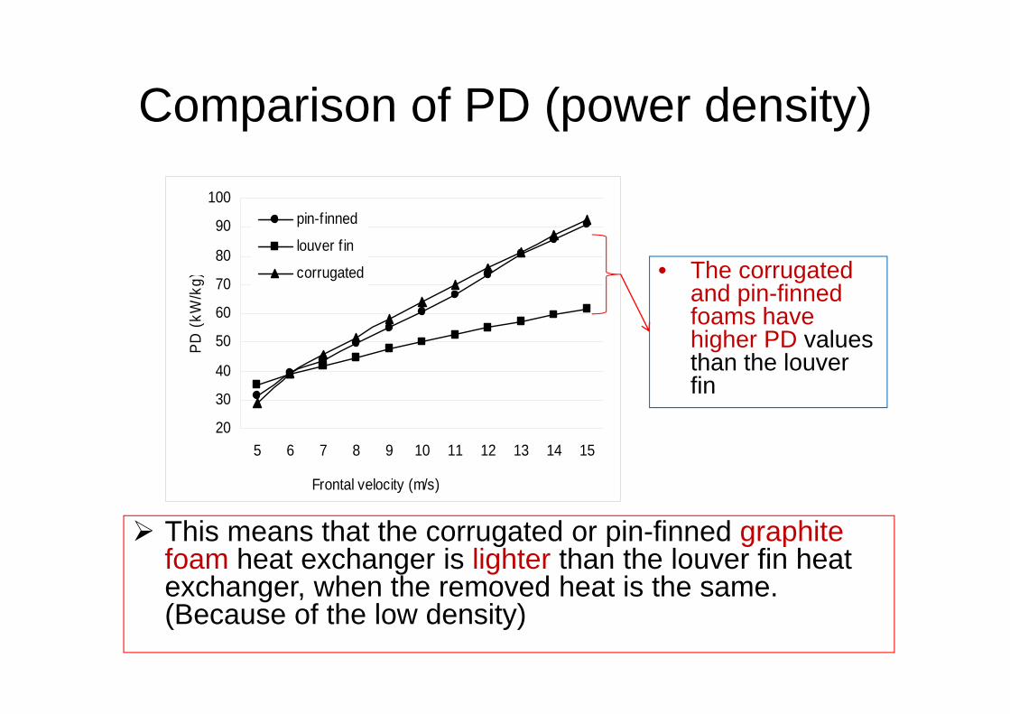
Comparison of PD (power density)
Frontal velocity (m/s)
20
30
40
50
60
70
80
90
100
5 6 7 8 9 10 11 12 13 14 15
PD (k
W/k
g)pin-f inned
louver f in
corrugated • The corrugated and pin-finned foams have higher PD values than the louver fin
This means that the corrugated or pin-finned graphite foam heat exchanger is lighter than the louver fin heat exchanger, when the removed heat is the same. (Because of the low density)

Comparison of CF (compactness factor )
When the removed heat is the same, the volume of the corrugated or pin-finned foam is much smaller than that of the louver fin.
Because of the open cells in the foam, the heat transfer surface is larger in the corrugated or pin-finned foam than in the louver fin.
• The CF value of the corrugated or pin-finned foam is higher than that of the louver fin.
Frontal velocity (m/s)
2000
4000
6000
8000
10000
12000
14000
16000
18000
5 6 7 8 9 10 11 12 13 14 15
CF
(kW
/m3)
pin-f inned
louver f in
corrugated
High compactness in graphite
foam

Conclusion of graphite foam heat exchanger• Low pressure drop and high thermal performance have
been provided by the corrugated and pin-finned graphite foams.
• The corrugated and pin-finned graphite foams have higher PD and CF values than the aluminium louver fin. This implies a light or compact cooling system in vehicles.
• By using an appropriate configuration of the graphite foam, it is possible to have the similar COP value as the aluminum louver fin.

Future work• New structure for heat exchangers
Due to space limitation, it might be good to change the position of heat exchanger. But when the position of the heat exchanger is changed, maybe a new structure of the heat exchanger is appropriate for the new position.
1) Maybe a countercurrent exchanger is good for the radiator which is on the top of driver compartment.
2) Designing a new configuration of heat exchanger, first the aluminum heat exchanger will be considered and analyzed. Later the graphite foam heat exchanger will be considered.
radiator 2
compartment
radiator 3
Radiator 1: countercurrent exchanger

Ideas about countercurrent HEX
a. Louver fin (cross flow) b. Louver fin (countercurrent flow)
d. Wave fin (countercurrent flow)c. Pin fin (countercurrent flow)

Thank youDiscussion and Questions