Advanced Brain Monitoring, Inc. - BIOPAC · D. Minimum System Requirements ... • B-Do not use the...
18
Setup Manual , CA 9 . 9 http://www. .com/
-
Upload
duongduong -
Category
Documents
-
view
214 -
download
1
Transcript of Advanced Brain Monitoring, Inc. - BIOPAC · D. Minimum System Requirements ... • B-Do not use the...

Setup Manual
.Lht!/
пн !ŜNJƻ /ŀƳƛƴƻ DƻƭŜǘŀ, CA 9оммт
улр.сурΦллсс9 http://www.ōƛƻLJŀŎ.com/

D0010-9 Rev 3.5 BIOPAC B-Alert X10 {ŜǘdzLJ 1
Table of Contents Chapter 1: Introduction and Safety Information ................................... 3
A. About the B-ALERT X10 ....................................................................................................... 3
B. Intended Use ....................................................................................................................... 3
C. Safety .................................................................................................................................. 4
D. Minimum System Requirements ........................................................................................ 6
D. Items Required for Use ........................................................................................................ 7
Chapter 2: Sensor Headset Use ................................................................ 8
A. Charging .............................................................................................................................. 8
B. Preparation ......................................................................................................................... 9
C. Application ........................................................................................................................ 11
D. Additional ECG Placements ............................................................................................... 15
E. Ready to Collect ................................................................................................................ 15
F. Post-session Clean-up ....................................................................................................... 16

D0010-9 Rev 3.5 BIOPAC B-Alert X10 {ŜǘdzLJ 3
Chapter 1: Introduction and Safety Information
A. About the B-ALERT X10 The B-ALERT X10 is an internally battery powered FDA-classified Type BF device intended for continuous use (7-9 hours). The B-ALERT X10 provides an integrated approach for wireless acquisition and recording of electroencephalographic (EEG), electrooculographic (EOG) and electrocardiographic (ECG) signals. The system utilizes the patented B-Alert Sensor Headset and EEG sensors, which record high quality EEG and be obtained in five-minutes of set-up time with no scalp preparation. The wireless technology allows the user to be untethered and move around the clinic (or in the field) while real time data is collected, displayed, and analyzed.
The B-ALERT X10 acquires nine channels of monopolar EEG recordings with a linked mastoid reference. The 10th channel is a programmable gain option that can be used for EOG or ECG. The B-ALERT X10 consists of: Head and Host Units for bi-directional transmission of digitized physiological signals, and a Sensor Headset Cap and Strip with EEG sensors sites in the frontal (Fz, F3 and F4), central (Cz, C3 and C4) and parietal-occipital (POz, P3, and P4) regions.
The Sensor Headset collects physiological signals from the sensors placed on the user sampling at 256 Hz. The headset performs analog-to-digital conversion, encoding, formatting and transmitting of all signals. The signals communicate using a 2.4 to 2.48 GHz radio transmitter. B-Alert Acquisition utilizes the bi-directional capabilities of the system to initiate scalp-electrode impedance monitoring, and monitors the battery capacity in the Head Unit. A custom ABM USB Host Device (B-Alert Dongle or ESU-MC) is used as the base unit affixed to the PC workstation.
B-Alert Acquisition software consists of several modules that allow the user to acquire,
store, view, and analyze physiological signals acquired by the wireless system. The software provides a simple graphical interface for establishing and controlling data acquisition. Patented algorithms can be selected to monitor artifacts that impact signal quality in real time and provide users feedback when thresholds (for artifact) are exceeded. EEG Power Spectral Densities, EEG classifications, and Heart rate measures can be generated in real-time or off-line.
B. Intended Use The B-Alert X10 system is intended for use in clinical and research settings, by trained technicians, to measure and record the electrical activity originating from the brain (EEG), the heart (ECG), and the eye muscles (EOG) and store the data in an ebs or edf format. The system is intended for data collection only, and is not intended for treatment and/or any type of monitoring of patients in a medical environment such as surgery, intensive care unit, etc. Any medical diagnosis related to the EEG should only be derived by a certified Physician using

D0010-9 Rev 3.5 BIOPAC B-Alert X10 {ŜǘdzLJ | 4
medically approved software. The ECG and EOG are not intended to be used for any type of diagnosis or treatment.
CAUTION! Read this manual carefully before using the B-ALERT X10.
C. Safety The B-ALERT X10 is designed to be applied by a trained technician. There are a number of warnings and cautions throughout this manual. Read them carefully: they are important to the use of the product. The information in this manual has been carefully checked and is believed to be accurate.
CONTRAINDICATIONS
• Do not use the B-ALERT X10 in an MRI environment. • Do not use the B-ALERT X10 when alarms based on EEG classification are required. • B-ALERT X10 has no alarms classifications (such as drowsiness). There are only alarms
for indications of excessive artifact. • Do not use the B-ALERT X10 as a substitute for clinical ECG. The B-Alert X10 is a
recording device, not a monitoring device. • Do not use the B-Alert X10 with high frequency (HF) surgical equipment. • Do not use the B-ALERT X10 in an environment where Defibrillation is common.
WARNINGS • Explosion Hazard. Do not use the B-ALERT X10 in an explosive atmosphere. • Explosion Hazard. Do not use the B-ALERT X10 in the presence of flammable anesthetics
or gases. • Explosion Hazard. Do not use the B-ALERT X10 battery recharging system with non-
rechargeable batteries. • EEG Leads, Strips and Sensor interfaces are not protected against the effects of
defibrillation. Damage to the device is possible if worn during defibrillation. • Not Defibrillator Proof. • Additional equipment connected to the patient must comply with the requirements of
IEC 60601-1-1. • The PC used with B-ALERT X10 must be placed outside the patient/client environment
(more than 3 meters or 10 feet) or the PC must comply with IEC 60601-1.1 • Permanent Damage and/or Warranty Voidance. B-ALERT X10 must be repaired by
authorized personnel only. Any evidence of opening the system, field service by non-authorized personnel, tampering, or any kind of system misuse or abuse shall void the warranty.

D0010-9 Rev 3.5 BIOPAC B-Alert X10 {ŜǘdzLJ 5
• Synapse Conductive Electrode Cream is recommended for use with the EEG sensors. Use of any conductive gel, cream or electrolyte other than Synapse may affect signal quality, signal accuracy or damage the EEG sensor.
• Avoid placement of EEG sensors or Synapse cream directly into an open wound.
CAUTIONS – General
• The B-ALERT X10 should only be applied by a trained technician. This model is not intended for in-home use without the assistance of a technician.
• Position conductive parts of the EEG, ECG and EOG sensors so that they do not contact other conductive parts and earth.
• Do not spray, pour, or spill any liquid on the B-ALERT X10, its connectors, switches, or openings, as this will cause permanent damage and void the Warranty.
• Do not use caustic or abrasive cleaning agents on the B-ALERT X10 or on the EEG sensors, as this will cause permanent damage and void the Warranty.
• This device has been tested and found to comply with the limits for medical devices to the IEC 60601 standards. These standards are designed to provide reasonable protection for safety and against harmful interference in a typical medical installation.
• To minimize the possible hazard caused by the summation of leakage currents when several equipments are interconnected, the B-ALERT X10 should be used in wireless mode only and should never be charged while being worn by the patient.
• Verify that all visible indicators illuminate during the startup (initialization) sequence. If any indicator is not lit, do not use the B-ALERT X10.
CAUTIONS – Batteries • Do not charge the batteries while wearing the Sensor Headset. • Do not recharge batteries that have been fully charged. • Follow local ordinances and recycling instructions regarding disposal or recycling of the
device and device components, including batteries. Batteries may leak or explode if used or disposed of improperly.
• The internal Li-Polymer batteries should only be replaced by the service department!

D0010-9 Rev 3.5 BIOPAC B-Alert X10 {ŜǘdzLJ 6
D. Minimum System Requirements • Personal computer (PC) with minimum PentiumTM 2.4 GHz processor; • Minimum of 1 GB of installed RAM memory and 4 MB virtual memory; • Windows XP or Windows 7 operating system; • .NET framework version 3.5 installed • Minimum of 50 MB hard disk space per 5-hour session; • One CD-ROM drive; • VGA or higher resolution video adapter; • One available USB port. • Monitor size between 15” and 21” required for Baseline acquisition.

D0010-9 Rev 3.5 BIOPAC B-Alert X10 {ŜǘdzLJ | 7
D. Items Required for Use
B-Alert X10 Sensor Headset
Sensor Strip
Neoprene Strap
Foam Sensors 12cc Syringe
ECG Leads (left) Mastoid (right)
Disposable Electrodes
Synapse Gel Bottle & Tube
Cleaning Tools - Tweezers & Electrode Brush
Tape Measure Zip-Linq Wall Charger &
X10 Cable Adapter
ABM USB Host device B-Alert Dongle
CD with installation, manual, and training
videos

D0010-9 Rev 3.5 BIOPAC B-Alert X10 {ŜǘdzLJ | 8
Chapter 2: Sensor Headset Use Note: This chapter presents a detailed, written process of a standard subject setup. For an additional demonstration, refer to the instructional videos provided with the included software.
A. Charging The B-Alert Sensor Headset should arrive fully charged and ready for use. For ongoing usage, it is recommended that you charge the headset the night before using. To recharge the Headset follow the steps below.
1. Verify the Headset is in the off position. Insert the X10 cable adapter into the sensor headset.
2. Plug the Mini-B connector into the X10 cable adapter and the USB-A connector into your computer’s USB port
3. Once power is recognized, the sensor headset will automatically begin charging, confirmed by a double blinking green LED pattern on the front of the headset.
4. Charging will automatically terminate once the batteries are fully charged, confirmed by a single blinking green LED pattern.
Brain map of a 9-electrode strip.
Front
Back
Cable Adapter Mini-B

D0010-9 Rev 3.5 BIOPAC B-Alert X10 {ŜǘdzLJ 9
Mastoid Leads
Fuzzy side of neoprene Triangle Strip Connector
B. Preparation
1. Preparing Sensor Headset a. With the fuzzy side of the
Neoprene facing out and the strip connector triangle pointing up.
b. Using a clean Neoprene Strap, feed the Strap ends through each side of the Sensor Headset strap holders and fasten the Velcro. Do this equally to both sides, but leave loose for easy application to subject later. The fuzzy side of the neoprene should be facing out away from the Sensor headset and the strip triangle should be pointing up.
c. Verify the Mastoid Leads are plugged into the system.
2. Preparing Strip a. Inspect the Strip and verify there are no rips or hard creases
on the Strip itself. Check the entire strip paying special care to spots prone to rips and creases.
CAUTION! Use of damaged or broken Strips may result in inaccurate EEG recordings.

D0010-9 Rev 3.5 BIOPAC B-Alert X10 {ŜǘdzLJ | 10
b. Attach the foam pieces to the sensor sites. Ensure the foam is centered within the black circle to maximize the contact surface between the sensor site and the foam.
c. Using the provided syringes with curved tip applied; fill each foam piece with synapse gel in one of two ways.
d. Place the syringe in the hole of the foam and dispense gel. You should see the gel begin filling the center of the foam.
e. The gel can also be dispensed into the
foam from the sides by pushing the tip into either side of the foam until it begins to fill the center.
f. Make sure to completely fill foam piece. Each sensor will hold 0.4-0.6 cc of synapse gel.
g. The foam should be saturated with gel
and the center hole should be filled to the top.

D0010-9 Rev 3.5 BIOPAC B-Alert X10 {ŜǘdzLJ 11
C. Application
3. Sensor Headset and Neoprene Strap
a. Measure the distance from the nasion to the inion (occipital bone).
b. Use an alcohol swab to wipe down areas where the sensors will be placed. Also clean Mastoid and ECG locations with an alcohol swab.
c. Place the Sensor Headset onto the subject’s head and tighten the Neoprene Strap to provide a snug fit.
d. Verify that the Neoprene Strap is centered on the subject and that it is not resting on the ears.
e. While holding the strip in front of the subject, with the foam pieces facing away from the face, attach the Strip to the front of the Neoprene Strap by feeding triangular tip through the hole adjacent to site Fz.
f. Carefully bring the Strip over the top of the subject’s head, verifying that the Strip is centered and that the subject’s inion is below the alignment hole. (See picture on next page).
Size Nasion - Inion Small 32.0 – 34.5 cm Medium >34.5 cm
CAUTION! Synapse gel should be used with all sensors and electrodes to avoid signal quality problems.
a.
d.
c.
Nasion Inion
D0010-9 Rev 3.5 BIOPAC B-Alert X10 {ŜǘdzLJ | 12
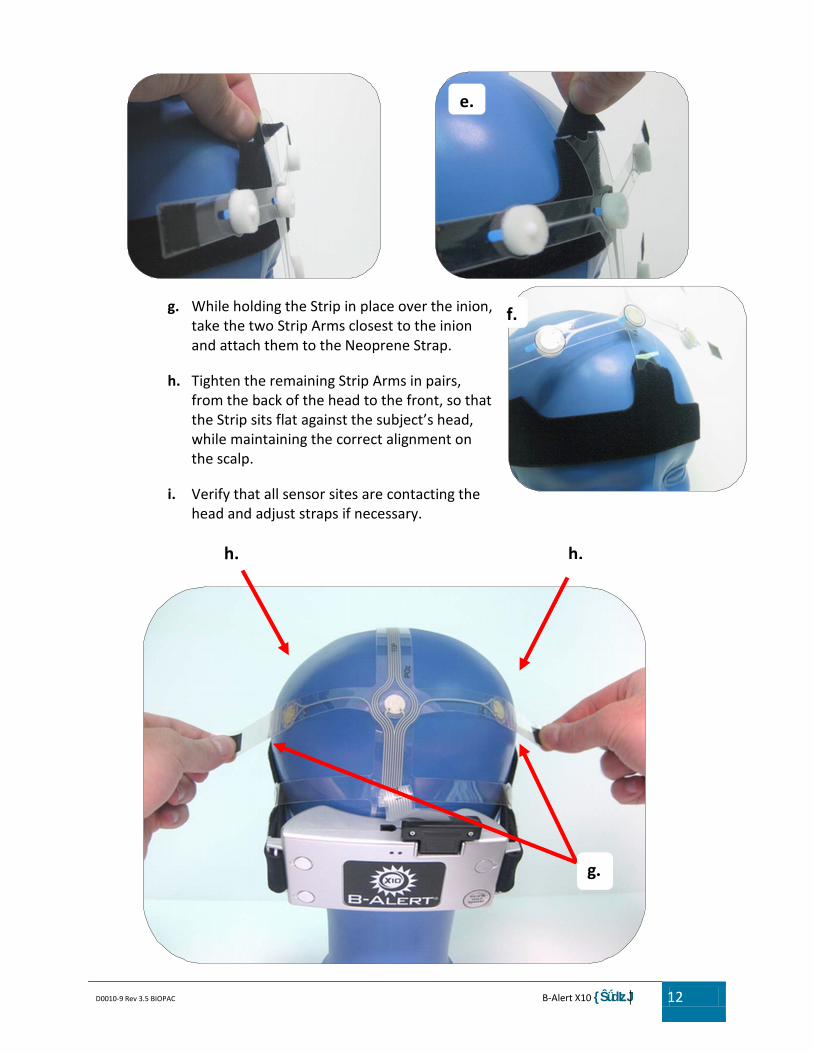
g. While holding the Strip in place over the inion, take the two Strip Arms closest to the inion and attach them to the Neoprene Strap.
h. Tighten the remaining Strip Arms in pairs, from the back of the head to the front, so that the Strip sits flat against the subject’s head, while maintaining the correct alignment on the scalp.
i. Verify that all sensor sites are contacting the head and adjust straps if necessary.
f.
e.
h. h.
g.

D0010-9 Rev 3.5 BIOPAC B-Alert X10 {ŜǘdzLJ 13
j. Gently plug connector on the back of the Strip into the Sensor Headset. The connection between headset and strip is snug, be gentle when plugging/unplug
k. If the subject complains about discomfort from any electrode, loosen individual Strip Arms.
j.
D0010-9 Rev 3.5 BIOPAC B-Alert X10 {ŜǘdzLJ 14
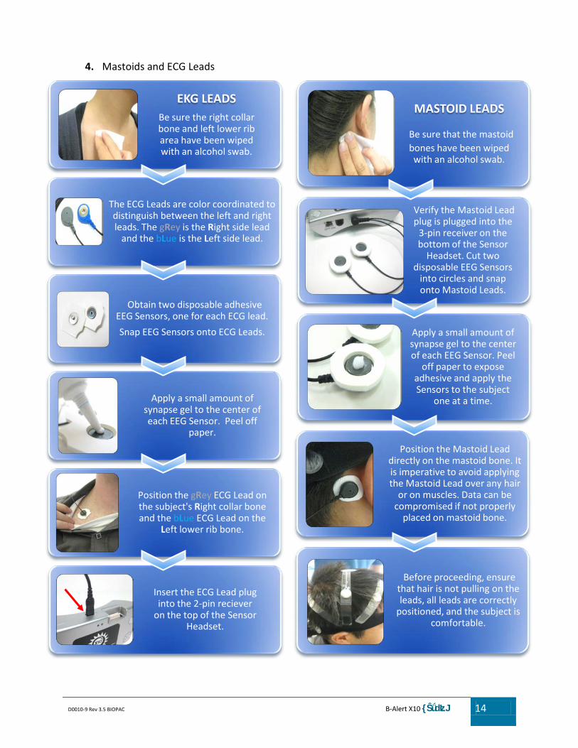
4. Mastoids and ECG Leads
MASTOID LEADS
Be sure that the mastoid bones have been wiped with an alcohol swab.
Verify the Mastoid Lead plug is plugged into the
3-pin receiver on the bottom of the Sensor
Headset. Cut two disposable EEG Sensors
into circles and snap onto Mastoid Leads.
Apply a small amount of synapse gel to the center of each EEG Sensor. Peel
off paper to expose adhesive and apply the Sensors to the subject
one at a time.
Position the Mastoid Lead directly on the mastoid bone. It is imperative to avoid applying the Mastoid Lead over any hair
or on muscles. Data can be compromised if not properly
placed on mastoid bone.
Before proceeding, ensure that hair is not pulling on the leads, all leads are correctly
positioned, and the subject is comfortable.
EKG LEADSBe sure the right collar bone and left lower rib area have been wiped with an alcohol swab.
The ECG Leads are color coordinated to distinguish between the left and right leads. The gRey is the Right side lead
and the bLue is the Left side lead.
Obtain two disposable adhesive EEG Sensors, one for each ECG lead.
Snap EEG Sensors onto ECG Leads.
Apply a small amount of synapse gel to the center of each EEG Sensor. Peel off
paper.
Position the gRey ECG Lead on the subject's Right collar bone and the bLue ECG Lead on the
Left lower rib bone.
Insert the ECG Lead plug into the 2-pin reciever
on the top of the Sensor Headset.

D0010-9 Rev 3.5 BIOPAC B-Alert X10 {ŜǘdzLJ 15
D. Additional ECG Placements The B-Alert ECG algorithms rely on peak to peak measurements to compute the beat to beat (and second to second) Heart Rate. The ECG signal is robust and the sensor placement is somewhat flexible. ABM's recommended placement is to have the Left (bLue) ECG Lead on the lower most rib and the Right (gRey) lead on the right collarbone. Alternative ECG placements however can be used if the recommended configuration is not ideal for a given application. For alternative ECG placement, the appropriate leads must be placed across the heart (bLue) lead ALWAYS on the Left side of participant and gRey lead always on the right side of the participant. The adhesive electrodes should be placed on parts of the participant where there is little potential for movement (from breathing or muscles) which can compromise signal integrity--(such as the ribs or collarbone. Contact ABM for additional information on alternative ECG placement.
E. Ready to Collect
1. Plug in ABM USB Host Device (B-Alert Dongle or ESU) to an available USB port on the computer running B-Alert Software.
2. Verify the Sensor Headset is synced to the B-Alert Dongle by switching on the Sensor Headset and viewing the indicator lights on the front of the Sensor Headset. The Sensor Headset has established connection when the green indicator light turns solid after 5-seconds. If the red indicator light stays on while the green indicator light is blinking, the headset is not properly connecting. Refer Chapter 6E for detail on how to re-sync a Headset to a ABM USB Host Device.
3. Maintaining BT Signal Quality:
a. Make sure the Sensor Headset and B-Alert Dongle are within 25 feet of each other.
b. Minimize the number of obstructions ( and avoid metal objects) in the line-of sight of the head and host units.
Not Connected Connected

D0010-9 Rev 3.5 BIOPAC B-Alert X10 {ŜǘdzLJ | 16
F. Post-session Clean-up
1. Removal of Sensor Headset and Electrodes
After testing is complete, turn off the sensor headset by sliding the switch to the
off position.
Carefully remove the EKG and mastoid leads from the
subject.
Gently unplug the strip from the headset and detach all
strip arms from the Neoprene Strap.
Lift strip away from subject and detach the front of the
strip from the Neoprene Strap.
Remove the headset and strap by lifting up, off the
head.
D0010-9 Rev 3.5 BIOPAC B-Alert X10 {ŜǘdzLJ 17
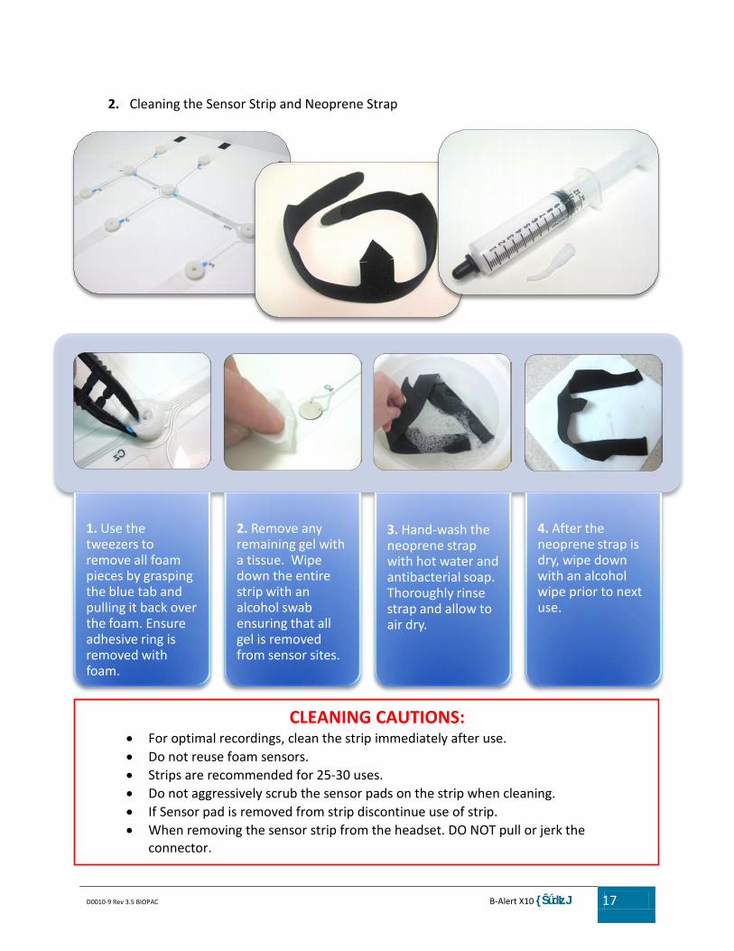
1. Use the tweezers to remove all foam pieces by grasping the blue tab and pulling it back over the foam. Ensure adhesive ring is removed with foam.
2. Remove any remaining gel with a tissue. Wipe down the entire strip with an alcohol swab ensuring that all gel is removed from sensor sites.
3. Hand-wash the neoprene strap with hot water and antibacterial soap. Thoroughly rinse strap and allow to air dry.
4. After the neoprene strap is dry, wipe down with an alcohol wipe prior to next use.
2. Cleaning the Sensor Strip and Neoprene Strap
CLEANING CAUTIONS:
• For optimal recordings, clean the strip immediately after use. • Do not reuse foam sensors. • Strips are recommended for 25-30 uses. • Do not aggressively scrub the sensor pads on the strip when cleaning. • If Sensor pad is removed from strip discontinue use of strip. • When removing the sensor strip from the headset. DO NOT pull or jerk the
connector.

D0010-9 Rev 3.5 BIOPAC B-Alert X10 {ŜǘdzLJ 18
Chapter 3: Software Acquisition Procedures
A. B-Alert Gauges The Gauges GUI will open with the Gauges tab active by default. Click the blue play button to begin acquisition, you will notice Elapsed Time counter will start. Left Click the appropriate Tabs to switch between display windows: Gauges, Raw Signals, Decontaminated (Decon) Signals, and Impedances. The impedance tab allows users to check impedances BEFORE starting an acquisition, and also provides color codes of data quality at each sensor site during live recording.
1. Gauges Meter Gauges: show B-Alert classifications averaged on a 3-second window, default to
show Workload, High Engagement, Distraction, and Heart Rate
2. Time Series Time Series Gauges - show second by
second EEG Data in 15 second windows (Displays Classification, PSD, and HR data)
3. Heat Map Heat Map Gauges: show 3-sec. averaged
distribution of power spectra intensity across sites (click PSD Button to Display)
5. Z-Score Z-Score Histogram: display second by
second Z-Scored values --Default set to Alpha (8-12Hz), Theta (3-7 Hz), and Heart
Gauges Window
Play/Pause Icon
Display Window Tabs
4. PSD Surface Map Gauges - show across-site
distribution of power spectra intensity for most recent 15 seconds
Elapsed Time
1
2
3
4
5
1
2
3
4
5