ADOPTION OF NEW CONCEPTS IN MATERIAL HANDLING · PDF fileadoption of new concepts in material...
6
ADOPTION OF NEW CONCEPTS IN MATERIAL HANDLING IN CEMENT AND OTHER MINERAL INDUSTRIES By Jai P. Gupta, Chief General Manager and P K Mittal, Chief General Manager HOLTEC Consulting Private Limited 1. Introduction Indian cement industry has witnessed rapid growth in past 2-3 decades. The overall production capacity of the industry, which used to be approximately 60 million tonnes in early 90s, has more than quadrupled in about 20 years. Such rapid growth has posed several challenges in front of the Industry, some of which are: • New projects are forced to go for difficult to access / approach limestone deposits. • Industry being forced to go away from the markets due to difficulties in land availability / acquisition. • Unit sizes becoming larger to harness economies of scale. The usual capacity of new production lines ranges from 5,000 – 10,000 TPD clinker production, as compared to 2000 to 3000 TPD in early 90s. This is leading to need for higher volumes to be handled. • Similar requirements are also emerging from coal industry, non ferrous metal industries etc. • The need for high capacity material movement at a faster rate and inadequacy of road networks in remote areas, leading to increases reliance on rail transportation. The paper covers majority of the suggestions relating to the material movement through rail routes. The majority of material transportation includes bulk transportation of Coal, clinker, flyash and cement. This paper covers certain concepts which could substantially reduce loading and unloading time. These concepts have been successfully employed by Holtec in cement as well as other industries, and could help the cement industry in optimizing expenses on material handling. The paper covers the following 3 concepts, i. In motion loading of clinker or coal in railway rakes. ii. Use of bottom discharge wagons for coal and clinker transport and its easy and fast unloading. iii. Use of wagon shifters to reduce the area for the industrial units required to have railway siding. The paper briefly covers the concept, principle of operation and how it could be adopted by the Industry. Likely benefits and certain pre-requisites, which are needed for adaptation are also covered to a certain extent. In case of any customized needs, Holtec could be consulted for further help. 1.1 IN MOTION LOADING OF CLINKER/ COAL IN RAILWAY RAKES For the material transport connectivity through railways, clinker/ coal loading is usually done through overland hoppers, constructed on top of the railway tracks and loading of material is done through telescopic chutes. Depending upon the capacity and speed requirements, more and more number of hoppers / silos can be constructed so that more number of wagons could be loaded simultaneously. As per the usual concept approximately one rake material is stored in the overland hoppers. The usual time taken for one complete rake, varies from 3-6 hrs depending upon the number of hoppers available for loading of material. Although more number of hoppers reduces total time for filling the rake, but adds to other complications, such as • High number of equipments, their drives.
Transcript of ADOPTION OF NEW CONCEPTS IN MATERIAL HANDLING · PDF fileadoption of new concepts in material...
ADOPTION OF NEW CONCEPTS IN MATERIAL HANDLING IN
CEMENT AND OTHER MINERAL INDUSTRIES
By
Jai P. Gupta, Chief General Manager and P K Mittal, Chief General Manager
HOLTEC Consulting Private Limited
1. Introduction
Indian cement industry has witnessed rapid growth in past 2-3 decades. The overall production capacity
of the industry, which used to be approximately 60 million tonnes in early 90s, has more than quadrupled in about 20 years. Such rapid growth has posed several challenges in front of the Industry, some of which
are:
• New projects are forced to go for difficult to access / approach limestone deposits.
• Industry being forced to go away from the markets due to difficulties in land availability /
acquisition.
• Unit sizes becoming larger to harness economies of scale. The usual capacity of new production lines
ranges from 5,000 – 10,000 TPD clinker production, as compared to 2000 to 3000 TPD in early 90s.
This is leading to need for higher volumes to be handled.
• Similar requirements are also emerging from coal industry, non ferrous metal industries etc.
• The need for high capacity material movement at a faster rate and inadequacy of road networks in
remote areas, leading to increases reliance on rail transportation.
The paper covers majority of the suggestions relating to the material movement through rail routes. The
majority of material transportation includes bulk transportation of Coal, clinker, flyash and cement. This
paper covers certain concepts which could substantially reduce loading and unloading time. These
concepts have been successfully employed by Holtec in cement as well as other industries, and could help
the cement industry in optimizing expenses on material handling.
The paper covers the following 3 concepts,
i. In motion loading of clinker or coal in railway rakes.
ii. Use of bottom discharge wagons for coal and clinker transport and its easy and fast
unloading.
iii. Use of wagon shifters to reduce the area for the industrial units required to have
railway siding.
The paper briefly covers the concept, principle of operation and how it could be adopted by the Industry.
Likely benefits and certain pre-requisites, which are needed for adaptation are also covered to a certain
extent. In case of any customized needs, Holtec could be consulted for further help.
1.1 IN MOTION LOADING OF CLINKER/ COAL IN RAILWAY RAKES
For the material transport connectivity through railways, clinker/ coal loading is usually done through
overland hoppers, constructed on top of the railway tracks and loading of material is done through telescopic chutes. Depending upon the capacity and speed requirements, more and more number of
hoppers / silos can be constructed so that more number of wagons could be loaded simultaneously. As
per the usual concept approximately one rake material is stored in the overland hoppers. The usual time
taken for one complete rake, varies from 3-6 hrs depending upon the number of hoppers available for
loading of material. Although more number of hoppers reduces total time for filling the rake, but adds to
other complications, such as
• High number of equipments, their drives.
• Heavy to very heavy civil construction.
• Constraint of more permanent structures, as per railway norms.
• Occupation of large area.
• More number of operators.
This paper suggests loading of rail rakes in motion (Rapid loading system). With Rapid loading system,
the entire rake could be loaded in about 60-80 minutes, from a single discharge point.
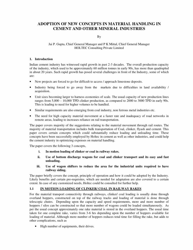
1.1.1 What is Rapid Loading?
In rapid loading of material, material is loaded on rake, while the railway rake is in motion. One silo (of
about one full rake capacity) is constructed on top of rail track. Below the hopper, another small hopper is
provided on load cells, which can accommodate about 1 wagon load of material. The above 2 hoppers are
connected through hydraulic gates, and large chute, so that within seconds, material gets transferred from
the main hopper to the pre-weigh hopper (mounted on load cell).
Before a rake arrives, silo is filled, so that fast material loading on the rake, does not get disturbed. In the
beginning the load cell hopper is filled with pre-weighed material. As soon as the wagon comes in
position, the loading starts and the complete wagon is loaded, by the time it crosses. During the period of
wagon change, pre-weigh hopper again receives the material from main hopper, so that by the time
another wagon comes into position, it is ready with the material. During this entire operation railway rake
moves at the speed of about 0.6 to 0.7 km / hr. That means a full rake of clinker (about 650 m in length)
is likely to get loaded in about 1 hr of time.
A typical pictorial view is shown in following figure:
Fig-1: Rapid Loading System in Operation
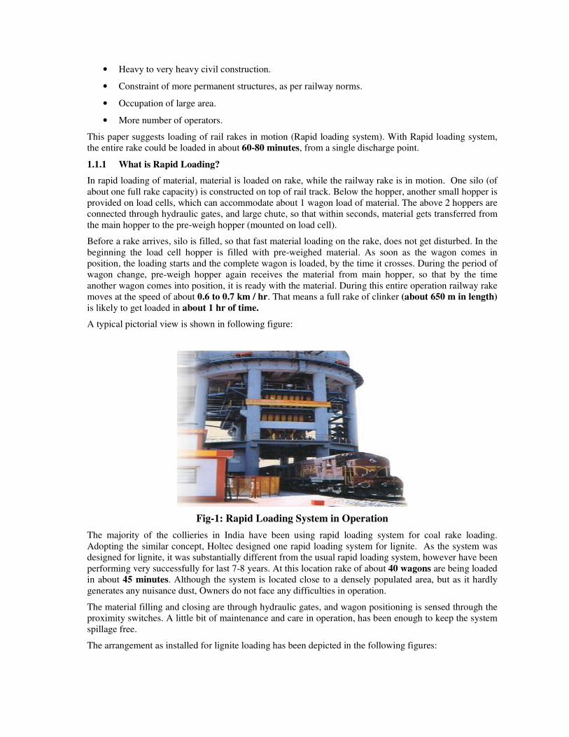
The majority of the collieries in India have been using rapid loading system for coal rake loading.
Adopting the similar concept, Holtec designed one rapid loading system for lignite. As the system was
designed for lignite, it was substantially different from the usual rapid loading system, however have been
performing very successfully for last 7-8 years. At this location rake of about 40 wagons are being loaded
in about 45 minutes. Although the system is located close to a densely populated area, but as it hardly
generates any nuisance dust, Owners do not face any difficulties in operation.
The material filling and closing are through hydraulic gates, and wagon positioning is sensed through the
proximity switches. A little bit of maintenance and care in operation, has been enough to keep the system
spillage free.
The arrangement as installed for lignite loading has been depicted in the following figures:
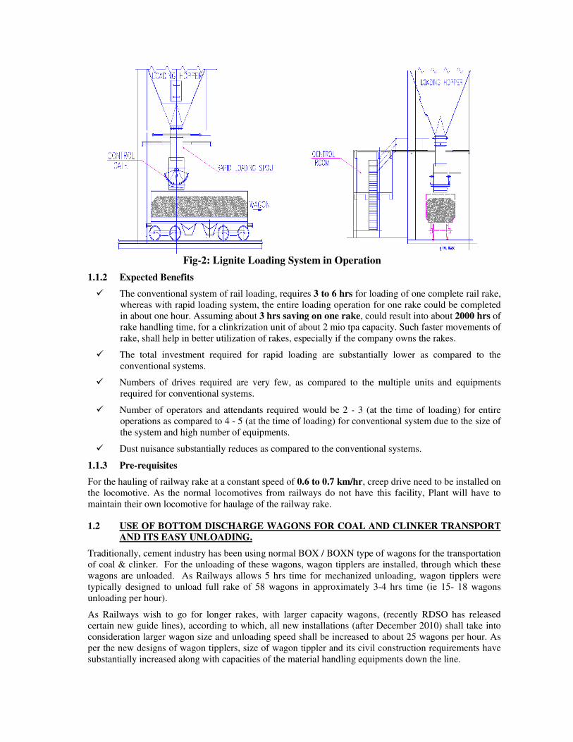
Fig-2: Lignite Loading System in Operation
1.1.2 Expected Benefits
� The conventional system of rail loading, requires 3 to 6 hrs for loading of one complete rail rake,
whereas with rapid loading system, the entire loading operation for one rake could be completed
in about one hour. Assuming about 3 hrs saving on one rake, could result into about 2000 hrs of
rake handling time, for a clinkrization unit of about 2 mio tpa capacity. Such faster movements of
rake, shall help in better utilization of rakes, especially if the company owns the rakes.
� The total investment required for rapid loading are substantially lower as compared to the
conventional systems.
� Numbers of drives required are very few, as compared to the multiple units and equipments
required for conventional systems.
� Number of operators and attendants required would be 2 - 3 (at the time of loading) for entire
operations as compared to 4 - 5 (at the time of loading) for conventional system due to the size of
the system and high number of equipments.
� Dust nuisance substantially reduces as compared to the conventional systems.
1.1.3 Pre-requisites
For the hauling of railway rake at a constant speed of 0.6 to 0.7 km/hr, creep drive need to be installed on
the locomotive. As the normal locomotives from railways do not have this facility, Plant will have to
maintain their own locomotive for haulage of the railway rake.
1.2 USE OF BOTTOM DISCHARGE WAGONS FOR COAL AND CLINKER TRANSPORT
AND ITS EASY UNLOADING.
Traditionally, cement industry has been using normal BOX / BOXN type of wagons for the transportation
of coal & clinker. For the unloading of these wagons, wagon tipplers are installed, through which these
wagons are unloaded. As Railways allows 5 hrs time for mechanized unloading, wagon tipplers were
typically designed to unload full rake of 58 wagons in approximately 3-4 hrs time (ie 15- 18 wagons
unloading per hour).
As Railways wish to go for longer rakes, with larger capacity wagons, (recently RDSO has released
certain new guide lines), according to which, all new installations (after December 2010) shall take into
consideration larger wagon size and unloading speed shall be increased to about 25 wagons per hour. As
per the new designs of wagon tipplers, size of wagon tippler and its civil construction requirements have
substantially increased along with capacities of the material handling equipments down the line.
As such installation of wagon tippler and associated auxiliaries was expensive, and recent enforcement
from railways, has further escalated the cost of installations of the wagon tippler and its associated
auxiliaries.
As against BOXC and BOXN type of wagon, allocated in cement industry, power plants are allocated
bottom discharge wagons (BOBRN), which can be emptied through pneumatic gates installed below the
wagons. For the discharge of such wagons, Thermal power plant installs long track hoppers with plough feeders. This is again quite expensive arrangement. As against normal track hoppers, Holtec designed a
very simple but effective system for lignite unloading in the year of 2002, which is running successfully
since then. A brief description of BOBRN type wagon is as below:
.Based on success of earlier designs system for Lignite, Holtec is designing another system for other
materials such as coal, copper concentrates and rock phosphate. All these materials are quite difficult to
flow and causes substantial amount of dust nuisance, accordingly the track hoppers are being designed.
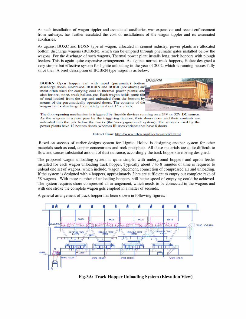
The proposed wagon unloading system is quite simple, with underground hoppers and apron feeder
installed for each wagon unloading track hopper. Typically about 7 to 8 minutes of time is required to
unload one set of wagons, which include, wagon placement, connection of compressed air and unloading. If the system is designed with 4 hoppers, approximately 2 hrs are sufficient to empty out complete rake of
58 wagons. With more number of unloading hoppers, still better speed of emptying could be achieved.
The system requires shore compressed air arrangement, which needs to be connected to the wagons and
with one stroke the complete wagon gets emptied in a matter of seconds.
A general arrangement of track hopper has been shown in following figures:
Fig-3A: Track Hopper Unloading System (Elevation View)
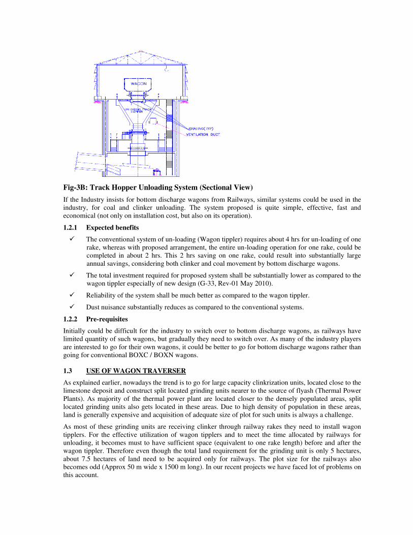
Fig-3B: Track Hopper Unloading System (Sectional View)
If the Industry insists for bottom discharge wagons from Railways, similar systems could be used in the
industry, for coal and clinker unloading. The system proposed is quite simple, effective, fast and
economical (not only on installation cost, but also on its operation).
1.2.1 Expected benefits
� The conventional system of un-loading (Wagon tippler) requires about 4 hrs for un-loading of one
rake, whereas with proposed arrangement, the entire un-loading operation for one rake, could be
completed in about 2 hrs. This 2 hrs saving on one rake, could result into substantially large
annual savings, considering both clinker and coal movement by bottom discharge wagons.
� The total investment required for proposed system shall be substantially lower as compared to the
wagon tippler especially of new design (G-33, Rev-01 May 2010).
� Reliability of the system shall be much better as compared to the wagon tippler.
� Dust nuisance substantially reduces as compared to the conventional systems.
1.2.2 Pre-requisites
Initially could be difficult for the industry to switch over to bottom discharge wagons, as railways have
limited quantity of such wagons, but gradually they need to switch over. As many of the industry players
are interested to go for their own wagons, it could be better to go for bottom discharge wagons rather than
going for conventional BOXC / BOXN wagons.
1.3 USE OF WAGON TRAVERSER
As explained earlier, nowadays the trend is to go for large capacity clinkrization units, located close to the
limestone deposit and construct split located grinding units nearer to the source of flyash (Thermal Power
Plants). As majority of the thermal power plant are located closer to the densely populated areas, split
located grinding units also gets located in these areas. Due to high density of population in these areas,
land is generally expensive and acquisition of adequate size of plot for such units is always a challenge.
As most of these grinding units are receiving clinker through railway rakes they need to install wagon
tipplers. For the effective utilization of wagon tipplers and to meet the time allocated by railways for
unloading, it becomes must to have sufficient space (equivalent to one rake length) before and after the
wagon tippler. Therefore even though the total land requirement for the grinding unit is only 5 hectares,
about 7.5 hectares of land need to be acquired only for railways. The plot size for the railways also
becomes odd (Approx 50 m wide x 1500 m long). In our recent projects we have faced lot of problems on
this account.
To tackle this issue one of the supplier’s for wagon tippler, came out with the solution of wagon traverser,
immediately after the wagon tippler. Keeping in mind the limitations of land and confidence on designs,
the wagon traverser are being installed in one of Holtec project.
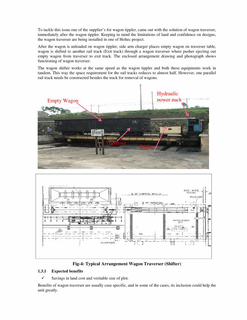
After the wagon is unloaded on wagon tippler, side arm charger places empty wagon on traverser table,
wagon is shifted to another rail track (Exit track) through a wagon traverser where pusher ejecting out
empty wagon from traverser to exit track. The enclosed arrangement drawing and photograph shows functioning of wagon traverser.
The wagon shifter works at the same speed as the wagon tippler and both these equipments work in
tandem. This way the space requirement for the rail tracks reduces to almost half. However, one parallel
rail track needs be constructed besides the track for removal of wagons.
Fig-4: Typical Arrangement Wagon Traverser (Shifter)
1.3.1 Expected benefits
� Savings in land cost and veritable size of plot.
Benefits of wagon traverser are usually case specific, and in some of the cases, its inclusion could help the
unit greatly.
Empty Wagon
Hydraulic
power pack
Pusher Traverser