ADJUSTMENT AND ANALYSIS OF FORCES IN A FLEXIBLE CRANKSHAFT …
8
QUARTERLY ISSN 1232-9312 4/2017 (107) PROBLEMY EKSPLOATACJI Journal of Machine Construction and Maintenance Krzysztof NOZDRZYKOWSKI Maritime University of Szczecin, Poland Institute of Basic Technical Sciences [email protected] ADJUSTMENT AND ANALYSIS OF FORCES IN A FLEXIBLE CRANKSHAFT SUPPORT SYSTEM Key words: flexible support system, adjustment and analysis of forces, rolling resistance. Abstract: The paper presents an innovative measurement system implementing flexible support of a crankshaft. Through adjustment of support conditions, deflection and strain of the crankshaft under its weight can be eliminated. The principles of the selection of forces in the flexible support system and an analysis of the impact of rolling resistance on the deformation of the measured object are presented. Dobór i analiza sił w układzie elastycznego podparcia wału korbowego Słowa kluczowe: układ elastycznego podparcia, dobór i analiza sił, opory tarcia tocznego. Streszczenie: W artykule przedstawiono nowatorskie rozwiązanie systemu pomiarowego z tzw. elastycznym podparciem wału korbowego. Zaprezentowany sposób elastycznego podparcia umożliwia, poprzez odpowiedni dobór warunków podparcia, wy- eliminowanie ugięć i odkształceń wału pod wpływem ciężaru własnego. Przedstawiono zasady doboru sił w podporach układu elastycznego podparcia oraz analizę oddziaływania oporów tarcia tocznego na odkształcenia obiektu mierzonego. Introduction Nowadays, research on the identification of geometric errors focuses mainly on small components commonly used in machines and other mechanisms. It is assumed, arbitrarily, that deflection and flexible strain of such elements caused by their weight are small and therefore insignificant. In practice, no analyses are conducted to eliminate their deflection or strain through the selection of proper support conditions. Similarly, the support of large machine components is also treated marginally. However, as it has been shown in [1–5], the strain of large cylindrical machine components may obtain significant values. In most cases, complete elimination of this type of distortion is impossible, especially in the case of large “slender” components (such as crankshafts or camshafts), which are highly prone to deformation. Therefore, in order to obtain reliable measurement results, strain of these elements should be analysed and, if possible, eliminated or minimized through appropriate adjustment of the support of the measured object. The existing solutions for crankshaft testing use the support of the crankshaft on rigid V-blocks of adjustable height. The supports are adjusted vertically to eliminate deflection of the crankshaft. It is practically impossible to obtain reliable results of measurements of a crankshaft supported on rigid V-blocks, since, due to the initial deflection and geometric errors, the measurements are affected by the positive or negative flexible strain of p. 63–70
Transcript of ADJUSTMENT AND ANALYSIS OF FORCES IN A FLEXIBLE CRANKSHAFT …

QUARTERLYISSN 1232-9312 4/2017 (107)
Problemy eksPloatacji
Journal of MachineC o n s t r u c t i o n and Maintenance
Krzysztof NOZDRZYKOWSKI Maritime University of Szczecin, PolandInstitute of Basic Technical [email protected]
ADJUSTMENT AND ANALYSIS OF FORCES IN A FLEXIBLE CRANKSHAFT SUPPORT SYSTEM
Key words: flexible support system, adjustment and analysis of forces, rolling resistance.
Abstract: The paper presents an innovative measurement system implementing flexible support of a crankshaft. Through adjustment of support conditions, deflection and strain of the crankshaft under its weight can be eliminated. The principles of the selection of forces in the flexible support system and an analysis of the impact of rolling resistance on the deformation of the measured object are presented.
Dobór i analiza sił w układzie elastycznego podparcia wału korbowego
Słowa kluczowe: układ elastycznego podparcia, dobór i analiza sił, opory tarcia tocznego.
Streszczenie: W artykule przedstawiono nowatorskie rozwiązanie systemu pomiarowego z tzw. elastycznym podparciem wału korbowego. Zaprezentowany sposób elastycznego podparcia umożliwia, poprzez odpowiedni dobór warunków podparcia, wy-eliminowanie ugięć i odkształceń wału pod wpływem ciężaru własnego. Przedstawiono zasady doboru sił w podporach układu elastycznego podparcia oraz analizę oddziaływania oporów tarcia tocznego na odkształcenia obiektu mierzonego.
Introduction
Nowadays, research on the identification ofgeometric errors focuses mainly on small components commonly used in machines and other mechanisms.It is assumed, arbitrarily, that deflection and flexiblestrain of such elements caused by their weight are small and therefore insignificant. In practice, no analysesare conducted to eliminate their deflection or strainthrough the selection of proper support conditions.Similarly, the support of large machine componentsis also treated marginally. However, as it has beenshownin[1–5],thestrainoflargecylindricalmachinecomponents may obtain significant values. In mostcases, complete elimination of this type of distortion
is impossible,especially in thecaseof large“slender”components (suchascrankshaftsorcamshafts),whichare highly prone to deformation. Therefore, in orderto obtain reliablemeasurement results, strain of theseelementsshouldbeanalysedand,ifpossible,eliminatedor minimized through appropriate adjustment of thesupportofthemeasuredobject.
The existing solutions for crankshaft testing use the supportofthecrankshaftonrigidV-blocksofadjustableheight.Thesupportsareadjustedverticallytoeliminatedeflectionofthecrankshaft.Itispracticallyimpossibleto obtain reliable results of measurements of a crankshaft supported on rigid V-blocks, since, due to the initialdeflection andgeometric errors, themeasurements areaffected by the positive or negative flexible strain of
p. 63–70

64 Journal of Machine Construction and Maintenance | PROBLEMY EKSPLOATACJI | 4/2017
variablevaluescausedbychangesinthestiffnessofthecrankshaftduringitsrotation.
The proposed solution of ameasuring device [6]providesforsettingthecrankshaftonexternaljournalsintwoarticulatedV-blocksandsupportingthecrankshaftat mid-section with a set of load distribution supports thatprovideequalandfixedloaddistributionforces.Thesolution lets thecrankshaft rest freelyon thesupports,which significantlyminimizes the change of its shapeand facilitates its rotation during the measurements.Although innovative, the solution has a number ofsubstantialflaws.Itfailstoeliminatepossibleunintendeddisplacement of the crankshaft, since, during rotation,there is typically constant contact of the irregular rounded surface of the main journals with the headsof thearticulated loaddistributionsupports.Assumingafixedvalueofpressureonallloaddistributionsupportsensures fixed values and directions of reaction forceson the supports, but it does not eliminate deflectionon the journals. Deflection on the main journals mayhave various values and additionally vary during theshaft’srotation.Thesolutionmaybesatisfactoryintheconditions of precise balancing of the crankshaft and its uniform stiffness. In practice, the stiffness of thecrankshaftvariesacrossitslength,especiallyinthecaseof crankshafts of a complex shape with asymmetrically distributedmainjournalsandcranks.
The existing measurement methods pose the difficulty of precise and unequivocal fixing of thecrankshaft in position due to the high and variablereaction forces produced by the supports and the resulting deformation which depends, additionally, onthevaluesandtypesofgeometricerrorsofthemeasuredobject[7].
1. Flexible support system – design and working principle
Taking into consideration the above mentioneddifficultiesintheassessmentofgeometricirregularitiesofcrankshafts,an innovativemeasurement systemhasbeenproposedthatusestheconceptoftheflexiblesupportofthemeasuredobject.Thesystemhasbeendevelopedonthebasisoftheauthor’spatentedsolution[8,9],withthe use of a dedicated measurement methodology and dedicated software for the processing of measurement results.Themeasurementsystemfacilitatespreciseandcomprehensivemeasurementsofgeometricerrorsoftheassemblies of crankshaft journals and straight shafts.TheconceptofflexiblesupportisshowninFig.1.
This type of support permits the elimination of theelasticdeflexionofthecrankshaftunderitsweight.Regardlesswhetherthecrankshaftrestsbetweenlockingpins or on V-blocks, the flexible supports distributedacross its mid-section compensate for the possible
elasticdeflection.Themeasurementsystemcanbeusedfor taking measurements at crankshaft manufacturing facilities, and engine mounting and engine overhaulfacilities.– The system is composed of the following:– Theflexiblesupportandbasesystem,– Themeasurementsystem,– Therevolutioncontrolsystem,and– Thedataprocessingandanalysissystem.
a)
Fig. 1. (a) Strain of cranks – rigid support; (b) flexible support concept
The flexible support system is made up ofa setofflexible supportsofanumberanddistributioncorresponding to the number and distribution of the main journals.Flexiblesupportseliminateelasticdeflectionofthecrankshaftunder itsweight.Pneumaticmotorscanbeusedasflexiblesupports.Theworkingmediumisair.Theflexiblesupportshavethepropertiesofself-aligning,elasticrollingV-blocks.Theirelasticitycompensatesfordeflectionaswellasverticalandhorizontalmovementof the crankshaft.The crankshaft is locked axially bymeansof two spherical tippinsofwhichone is rigid,whiletheotheriselastic,andtheysettheaxialdirection.This type of base for the crankshaft ensures that it has continuouscontactwiththelockingpins,regardlessofanypossibleaxialelasticstrain,whilethepressureforceisself-adjustable.
The measurement system is composed of a truck withatripodandameasuringsensormountedonit.Thetruckmoves(backlashfree)alongpreciseguidebars.
The system is equipped with a crankshaft rotation control system,which facilitates continuous recordingof the measurement data and feeding it into the computer memory.Measurementresults,includingcomprehensivedata on crankshaft shape and position errors, areprocessed for the determination of geometric errors.Calculations are performed by proprietary software,whichisanintegralpartofthemeasurementsystem.
Figure 2 presents the main components of theproposedsystem.
The main journals (2) of the crankshaft (1) reston a set offlexible loaddistribution supports (5).Thesupportsareequippedwithself-aligningrollingV-blockheads (6) which, in collaboration with actuators (10)
b)

Journal of Machine Construction and Maintenance | PROBLEMY EKSPLOATACJI | 4/2017 65
(poweredbyacertainmedium),providealldegreesoffreedom.The flexible supports provide passive forcesthat eliminate the elastic deflection of the measuredobjectandsimultaniouslycompensateforanymovement(displacement) caused by its geometric irregularities.Thevaluesofpressurevariablespi and the corresponding forcesprovidedbytheactuators(10)oftheflexibleloaddistributionsupports(5)areadjustedonancontinuousbasis by means of ARA-PNEUMATIK Tecno-basicPRE-I1-06-20-15 proportionate current-controlledreduction valves (15). The settings (manometer-controlled (16)) are adjusted individually, dependingonthecrankshaftdesign,sothatelasticstrainmeasuredon the main journals is eliminated, and the sphericaltippins(3)and(4),whichconstitute themeasurementbase (used for further determination of geometric errors),donotcarryverticalorhorizontalloads.Valuesof force variables (depending on the crankshaft turnangle)providedateachoftheflexiblesupportscanbedetermined with the use of software for the calculation ofthestrengthofmachineparts(e.g.,modelledbythefiniteelementmethod),assumingthatdeflectiononeachof themain journals equals zero or is not larger thanacertainpredefinedvalue[9,10].
TestsperformedwiththeuseoftheNastran2010strength calculation software showed that, in order toobtain zero-value deflection on themain journals, thevaluesofloaddistributionforcesappliedtoeverymainjournal must change, not only across the crankshaft’slength,but also in coordinationwith the changeof itsturn angle on the supports [9]. Figure 3 presents thedistribution of forces for four typical angle positions of
Fig. 2. Main components of the measurement system; the crankshaft is locked in locking pins
the crankshaft which ensure zero-value deflection onthemain journals, as determinedby theNastran 2010strength calculation software for the crankshaft of the mediumspeedmainengineoftheBuckauWolfR8DV136ship.
Changes of force values, obtained throughchanges of in the pressure of the medium powering the actuators of the load distribution supports, do notguarantee precise and unequivocal adjustment of therequiredloaddistributionforces.Realvaluesofforcesprovided by the pressure-controlled supports dependon a number of properties of the actuator, such asfrictional resistance, the type of powering medium,theshapeofitscomponents,materials,ordesign.ThissolutionadditionallyutilizesSPAISFT5367-4|IP68|(7)strain gauge force transducers with electrical ambient temperaturecompensation,placedbetweentheheads(6)andactuators(10)oftheflexiblesupports(5).Thus,therequired force is the parameter that controls the pressure ofthecontrolvalves(15).Thepressureintheactuators(10)oftheflexiblesupports(5)isforce-controlledandcorrespondstotherequiredvalueoftheloaddistributionforce.AdiagramoftheflexiblesupportcontrolsystemispresentedinFig.4.
The crankshaft is locked in the axial direction by means of pins (3) and (4), of which one is rigid andtheother oneprovides the axial pressure force,whichguarantees continuous contact of the crankshaft with the lockingpins.
Oncethecrankshaftisplacedonthesupportsandthedefinedvaluesofpressureprovidedbythesupportsissetbymeansofthecontrolvalves(15),theposition
66 Journal of Machine Construction and Maintenance | PROBLEMY EKSPLOATACJI | 4/2017
a)
b)
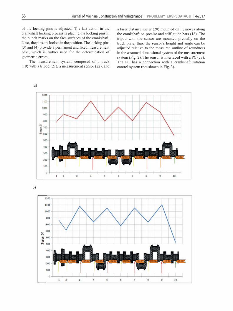
of the locking pins is adjusted. The last action in thecrankshaft locking process is placing the locking pins in thepunchmarksonthefacesurfacesofthecrankshaft.Next,thepinsarelockedintheposition.Thelockingpins(3)and(4)provideapermanentandfixedmeasurementbase, which is further used for the determination ofgeometricerrors.
The measurement system, composed of a truck(19)withatripod(21),ameasurementsensor(22),and
alaserdistancemeter(20)mountedonit,movesalongthecrankshaftonpreciseandstiffguidebars(18).Thetripod with the sensor are mounted pivotally on thetruckplate; thus, the sensor’sheight andanglecanbeadjusted relative to themeasuredoutlineof roundnessin the assumed dimensional system of the measurement system(Fig.2).ThesensorisinterfacedwithaPC(23).The PC has a connection with a crankshaft rotation controlsystem(notshowninFig.3).

Journal of Machine Construction and Maintenance | PROBLEMY EKSPLOATACJI | 4/2017 67
Fig. 3. Distribution of forces for selected angle positions of the crankshaft which ensure zero-value deflection on main journals (engine of the Buckau Wolf R8DV 136): (a) 0° turn angle; (b) 90° turn angle; (c) 180° turn angle; (d) 270°
turn angle
c)
d)
Fig. 4. Flexible support control system
The engine (12), controlled by a frequencyconverter, drives the shaft by means of a flexibleconnector (13) equipped with a crankshaft-loaddistributionmechanism.
The main pneumatic supply system includes avalve(8),amanometer(11),andabalancingtank(17).Thepressurepinthesupplycord(9)ishigherthanthepressurepiinthepneumaticactuators(10)oftheflexibleloaddistributionsupports(5).
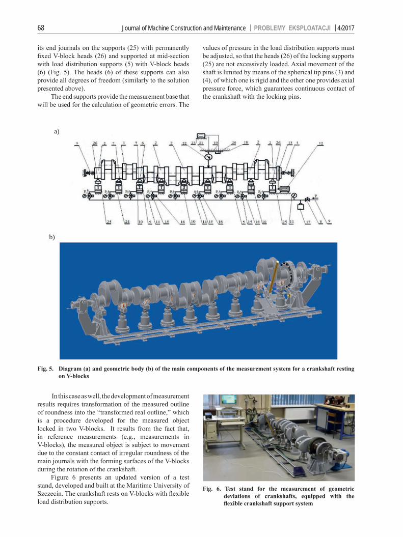
If the outer face surfaces of the crankshaft are not punch-marked, the crankshaftmust be basedwith
68 Journal of Machine Construction and Maintenance | PROBLEMY EKSPLOATACJI | 4/2017
itsendjournalsonthesupports(25)withpermanentlyfixedV-blockheads(26)andsupportedatmid-sectionwith loaddistributionsupports (5)withV-blockheads(6) (Fig. 5).The heads (6) of these supports can alsoprovidealldegreesoffreedom(similarlytothesolutionpresentedabove).
Theendsupportsprovidethemeasurementbasethatwillbeusedforthecalculationofgeometricerrors.The
valuesofpressureintheloaddistributionsupportsmustbeadjusted,sothattheheads(26)ofthelockingsupports(25)arenotexcessivelyloaded.Axialmovementoftheshaftislimitedbymeansofthesphericaltippins(3)and(4),ofwhichoneisrigidandtheotheroneprovidesaxialpressureforce,whichguaranteescontinuouscontactofthecrankshaftwiththelockingpins.
a)
b)
Fig. 5. Diagram (a) and geometric body (b) of the main components of the measurement system for a crankshaft resting on V-blocks
Inthiscaseaswell,thedevelopmentofmeasurementresults requires transformation of the measured outline ofroundnessintothe“transformedrealoutline,”whichis a procedure developed for the measured objectlocked in twoV-blocks. It results from the fact that,in reference measurements (e.g., measurements inV-blocks),themeasuredobjectissubjecttomovementdue to the constant contact of irregular roundness of the mainjournalswiththeformingsurfacesoftheV-blocksduringtherotationofthecrankshaft.
Figure 6 presents an updated version of a teststand,developedandbuiltattheMaritimeUniversityofSzczecin.ThecrankshaftrestsonV-blockswithflexibleloaddistributionsupports.
Fig. 6. Test stand for the measurement of geometric deviations of crankshafts, equipped with the flexible crankshaft support system
Journal of Machine Construction and Maintenance | PROBLEMY EKSPLOATACJI | 4/2017 69
2. Analysis of forces in the flexible support system
Theflexiblesupportsystempermitstheeliminationof the elastic deflection of crankshafts during theirmeasurements.Theprerequisitefortheproperoperationoftheflexiblesupportsystemisthecorrectselectionofthe number of supports and their distribution as well as theadjustmentofthepressureand,inconsequence,theforces provided by the supports.As shown in [9, 10],any change to the recommended support conditions results in the occurrence of the deflection of variablevalues. It results from the fact that the crankshaft isa highlyflexible component, and its cranks reactwithoneanother.
Fig. 7. Determination of the rolling resistance of load distribution support heads
Due to the high flexibility of the crankshaft, itsdeflection should be considered in both the verticaland horizontal planes. The flexible supports provideapassiveforcewhicheliminatesdeflection.Theheadsofthesupports,designedtoprovidealldegreesoffreedom,donot impedeanypossiblemovementof the journalslocked in them.Themovementmaybe causedby thefact that the centre of the cross section outline measured does not line up with the rotation axis provided bythelockingpinsorV-blocks.Asaresult, thecentreofthe cross section outline measured and the supporting headsmove eccentrically relative to the rotation axis.Themovementiscompensatedforintheverticalplanethrough changing the values of the load distributionforces.Inthehorizontalplane,themovementofjournalsis compensated for by the susceptibility to rolling of the load distribution support heads. Considering theloads carried by the flexible supports, variable forces
of rolling resistance occur at the contact surface of the supportheadguidebars,whichreactwiththecrankshaftjournals.Theforcesmayaffectthehorizontaldeflectionofthecrankshaft.
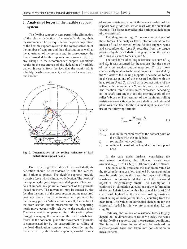
The diagram in Fig. 7 presents an analysis ofthese forces.The analysis takes into consideration theimpact of load Q carriedby theflexiblesupportheadsand circumferential force Fo resulting from the torque providedbythecrankshaftdrivingsystemonthevaluesof rolling resistance forces G1 and G2.
The total force of rolling resistance is a sum of G1 and G2.Itwasassumedfortheanalysisthatthecentreof the cross section outline measured O may moveeccentricallyrelativetotherotationaxisO1providedbytheV-blocksofthelockingsupports.Thereactionforcesin the contact points of the measured outline with the head rollers S1and S2,aswellasincontactpointsoftherollers with the guide bars N1 and N2,weredetermined.The reaction force values were expressed dependingon the shaft turn angle φ and the opening angle of the rollerV-blockφ.Theresultantofthemaximumrollingresistance force acting on the crankshaft in the horizontal plane was calculated for the assumed input data with the use of the following formula:
(1)
where:Nc max – maximum reaction force at the contact point of
therollerswiththeguidebars,ft – rollingfrictioncoefficient,r2 – radius of the roll of the load distribution support
head.
In the case under analysis, considering themeasurement conditions, the following values wereassumed: Ncmax=1234.4N,ft=0,012mm,andr2=30mm.
The calculation produced themaximum value oftheforceunderanalysislessthan0.5N.Anassumptionmay bemade that, in this case, the impact of rollingresistance on horizontal deflection of the measuredobject is insignificantly small. The assumption isconfirmedbysimulationcalculationsofthedeformationofthecrankshaftloadedwithahorizontalforceof5N(i.e.10-foldhigherthanthecalculatedrollingresistanceforce)actingonmainjournal(No.7)countingfromthegear train. The values of horizontal deflection for thecrankshaft loaded in thiswayare smaller than1.5μm(Fig.8).
Certainly, the values of resistance forces largelydependonthedimensionsofrollerV-blocks,theheads of the flexible supports, andmeasurement conditions.The impact of these forces should be analysed on a case-by-case basis and taken into consideration in measurements.
TN frc
c tmax
max=⋅
2

70 Journal of Machine Construction and Maintenance | PROBLEMY EKSPLOATACJI | 4/2017
Fig. 8. Horizontal strain of the crankshaft loaded with a horizontal force of 5 N
Summary
Theproposedflexible support systempermits theelimination of the elastic deflection of the crankshaftcaused by its weight. Regardless of whether thecrankshaft is locked in locking pins or V-blocks, theelements compensating for elastic strain of the crankshaft aretheflexiblesupportsdistributedatthemid-sectionofthe crankshaft.Thismeasurement system can be usedfor measurements taken at crankshaft manufacturing facilities, and engine mounting and engine overhaulfacilities.
References
1. NozdrzykowskiK.:Analizabłędupomiaruodchył-ki okrągłości wynikającego z nieprostopadłościpromieni zarysu kształtu przedmiotu mierzonegodostycznychwstałychpunktachpodparciapryzmustalających.2008,PomiaryAutomatykaKontrola,vol.54,No12,pp.848–850.
2. Nozdrzykowski K.: Analiza błędu pomiaru od-chyłki położenia osi spowodowanego wynikającąz tej odchyłki mimośrodowością przemieszczaniasię środka mierzonego zarysu okrągłości. 2011,Pomiary Automatyka Kontrola, vol. 57, No 3, pp.281–283.
3. Nozdrzykowski K.: Analysis of RoundnessDeviation Measurement Error Caused byDeformationsofaMeasuredObjectSetinV-Blocks.2009, Polish Journal of Environmental Studies, vol.18,No.2A,pp.165–169.
4. SadowskiA.,MiernikE.,SobolJ.:Metrologiadłu-gościikąta.WNT,Warszawa1978.
5. TomaszewskiA.:Podstawynowoczesnejmetrologii.1978,WNT,Warszawa,secondedition,amended.
6. Kuźniewski B.: Crankshaft measurement device.1978,Patentapplicationno.P137720.
7. JĕrábekK.,VondráčkováT., VoštováV.: IncreaseoftheEffectiveProductionofCrankshaftsforShipEngines.2016,NašeMore,No.63(4),pp.283–288.
8. Nozdrzykowski K.: Amethod and device for themeasurementof shapedeviationsandpositionsofaxesofcrankshaftmain journals.2015,PatentPL218653B1,patentapplicationno.P393829.
9. Nozdrzykowski K.: Metodyka pomiarów geo-metrycznych odchyłek powierzchni walcowychwielkogabarytowych elementówmaszyn na przy-kładzie wałów korbowych silników okrętowych.2013,WydawnictwoNaukoweAkademiiMorskiej wSzczecinie.
10. NozdrzykowskiK.:PreventionofElasticStrainsinFlexibleLargeSizeMachinePartswiththeUseofElasticSupport.2015,MachineDynamicsResearch,vol.39,No2,pp.11–22.