Adiabatic Systems° - BSJ
13
Adiabatic Systems° for heat exchangers and condensers
Transcript of Adiabatic Systems° - BSJ
Adiabatic Systems°for heat exchangers and condensers

Demand, idea, seriesThe adiabatic cooling system is a patented condenser system with up to two subcooling
sections. Depending on the installation location and operating conditions, a condensing temperature of 35°C can be
achieved although the liquid is actually cooled by a further 10 K. This makes it possible to supply a refrigeration machine
with liquid (for example R134a) at a maximum temperature of 25°C. In many cases this allows a refrigeration machine
one or two rating classes lower to be selected whilst still providing the same refrigeration capacity. The system has been
developed in response to customer demand and is now installed as standard.
Given the high exchanger surfaces in the adiabatic heat exchanger systems, a high hourly rate of free cooling is also
possible. With medium temperatures from 18°C to 12°C, this account for around 3000 - 4000 hours a year in many sectors
in Germany. During this period, no refrigeration machine is needed. Energy can therefore be saved hour for hour.
Adiabatic Systems°Strategic all-rounders among heat exchangers and condensers
Adiabatic heat exchangers and condensers have a pipe construction which runs underneath or to the side of the heat
exchanger with integral spray jets, allowing the intake temperature to be reduced by adiabatic means where external
temperatures are high. Water in aerosol form is sprayed into the intake air from the spray jets, with evaporative cooling
achieving a marked cooling effect.
Customised for a precisely defi ned application, they therefore extract as much as is needed in the given performance
framework and emit as little as possible in the name of effi ciency.
The CABERO product range distinguishes offers two distinct systems. Different spray patterns, droplet sizes and pre-
pressure at the jet form the basis of these decisions and are suitable for a variety of requirements. The LPSS system is
mainly defi ned by its saturation of the incoming air, whereas the HPSS produces partially hybrid operation.
LPSS - Low Pressure Spray Systemwith a system pressure of 1.5 - 2.5 bar.
HPSS - High Pressure Spray System with a system pressure of 2.0 - 4.0 bar. The additional volume of water produces a partially hybrid system for saturation
of the air.
With both systems, medium outlet temperatures are below the ambient temperature, depending on the design.
With CABERO's economic calculations, you can quickly fi nd the ideal solution for your needs. Your CABERO adviser
will be happy to show you the device and calculate your investment versus your savings in running costs.
01 02
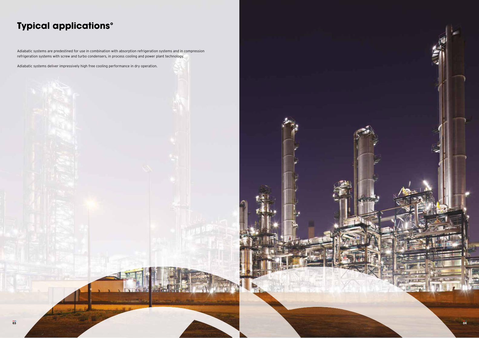
Typical applications°
Adiabatic systems are predestined for use in combination with absorption refrigeration systems and in compression
refrigeration systems with screw and turbo condensers, in process cooling and power plant technology.
Adiabatic systems deliver impressively high free cooling performance in dry operation.
03 04
Dry and adiabatic operation°
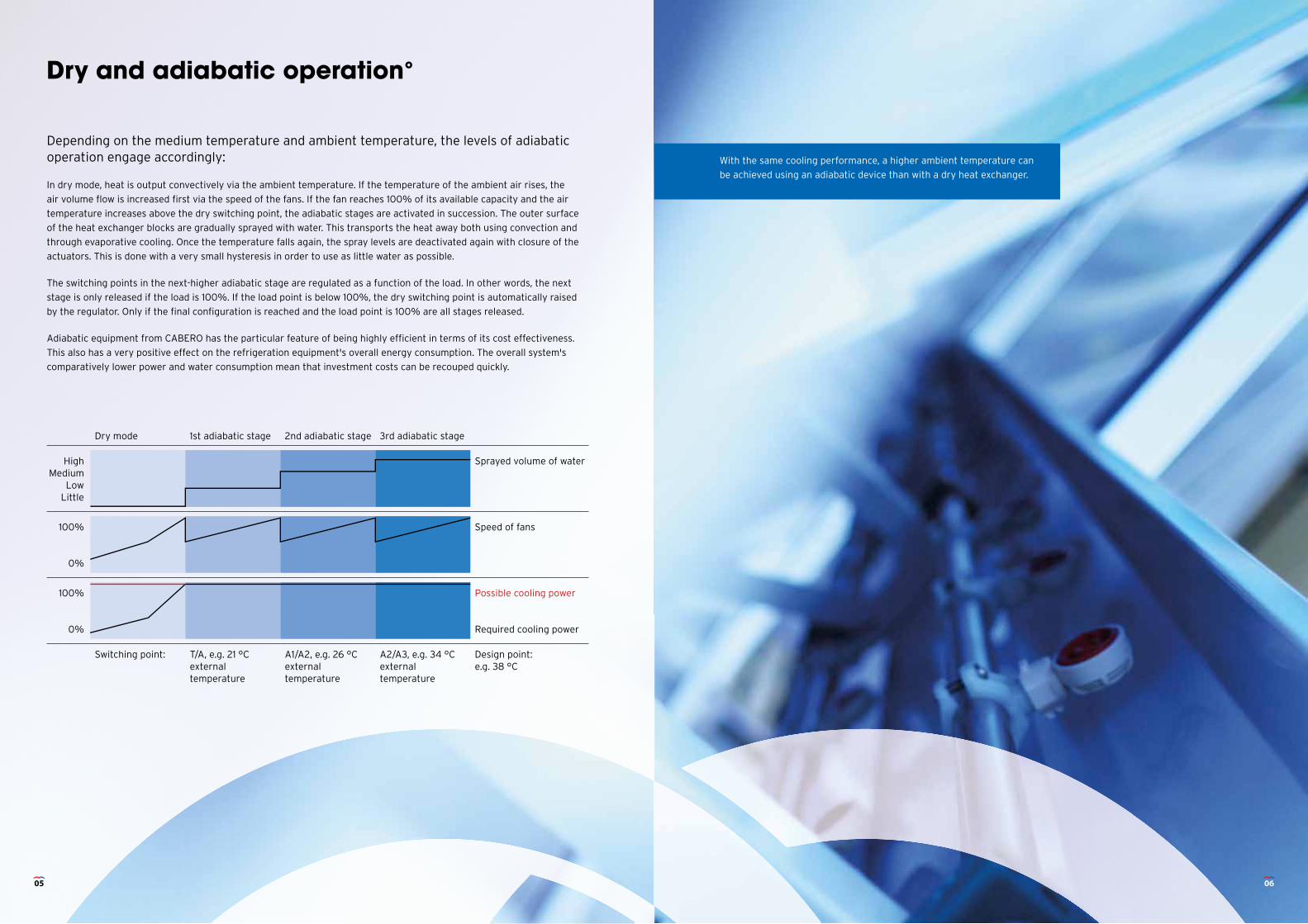
Depending on the medium temperature and ambient temperature, the levels of adiabatic operation engage accordingly:
In dry mode, heat is output convectively via the ambient temperature. If the temperature of the ambient air rises, the
air volume fl ow is increased fi rst via the speed of the fans. If the fan reaches 100% of its available capacity and the air
temperature increases above the dry switching point, the adiabatic stages are activated in succession. The outer surface
of the heat exchanger blocks are gradually sprayed with water. This transports the heat away both using convection and
through evaporative cooling. Once the temperature falls again, the spray levels are deactivated again with closure of the
actuators. This is done with a very small hysteresis in order to use as little water as possible.
The switching points in the next-higher adiabatic stage are regulated as a function of the load. In other words, the next
stage is only released if the load is 100%. If the load point is below 100%, the dry switching point is automatically raised
by the regulator. Only if the fi nal confi guration is reached and the load point is 100% are all stages released.
Adiabatic equipment from CABERO has the particular feature of being highly effi cient in terms of its cost effectiveness.
This also has a very positive effect on the refrigeration equipment's overall energy consumption. The overall system's
comparatively lower power and water consumption mean that investment costs can be recouped quickly.
With the same cooling performance, a higher ambient temperature can
be achieved using an adiabatic device than with a dry heat exchanger.
Dry mode 1st adiabatic stage 2nd adiabatic stage 3rd adiabatic stage
HighMedium
LowLittle
Sprayed volume of water
100%
0%
Speed of fans
100%
0%
Possible cooling power
Required cooling power
Switching point: T/A, e.g. 21 °Cexternal temperature
A1/A2, e.g. 26 °Cexternaltemperature
A2/A3, e.g. 34 °Cexternal temperature
Design point:e.g. 38 °C
05 06
Structure and material°
All CABERO equipment is measured by neutral testing institutions (such as DMT) before it is series-produced.
CABERO also maintains contact with many operators to continue monitoring equipment measurements and to assess the
energy consumption of different systems. This information is used for further development and optimisation purposes.
Possible constructions Tabletop equipment, V-shape, W-shape, jumbo
The carriers are made from zinc-plated, powder-coated steel and come in the standard colour RAL 9010. Any further RAL
colour can be produced as a special order.
Pipes Copper and stainless steel, depending on the application
Adiabatic system Stainless steel with plastic jets
Actuator / solenoid valve Electric ball valve, with hand switch, allowing the ball valve to be opened or closed manually in the event of a fault.
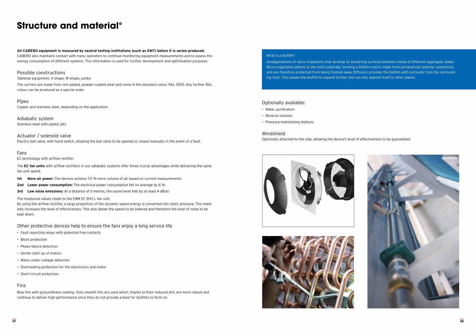
Fans EC technology with airflow rectifier
The EC fan units with airflow rectifiers in our adiabatic systems offer three crucial advantages while delivering the same
fan unit speed:
1st More air power: The devices achieve 7.5 % more volume of air based on current measurements
2nd Lower power consumption: The electrical power consumption fell on average by 6 %
3rd Low noise emissions: At a distance of 5 metres, the sound level falls by at least 4 dB(A)
The measured values relate to the EBM EC 900 L fan unit.
By using the airflow rectifier, a large proportion of the dynamic speed energy is converted into static pressure. This mark-
edly increases the level of effectiveness. This also allows the speed to be lowered and therefore the level of noise to be
kept down.
Other protective devices help to ensure the fans enjoy a long service life• Fault reporting relays with potential-free contacts
• Block protection
• Phase failure detection
• Gentle start-up of motors
• Mains under-voltage detection
• Overheating protection for the electronics and motor
• Short-circuit protection
FinsBlue fins with polyurethane coating. Only smooth fins are used which, thanks to their reduced dirt, are more robust and
continue to deliver high performance since they do not provide a base for biofilms to form on.
Optionally available: • Water purification
• Reverse osmosis
• Pressure-maintaining stations
Windshield Optionally attached to the side, allowing the device's level of effectiveness to be guaranteed.
What is a biofilm?
Amalgamations of micro-organisms that develop on bordering surfaces between media of different aggregate states.
Micro-organisms adhere to the solid substrate, forming a biofilm matrix made from extracellular polymer substances
and are therefore protected from being flushed away. Diffusion provides the biofilm with nutrients from the surround-
ing fluid. This causes the biofilm to expand further and can also deposit itself in other places.
07 08
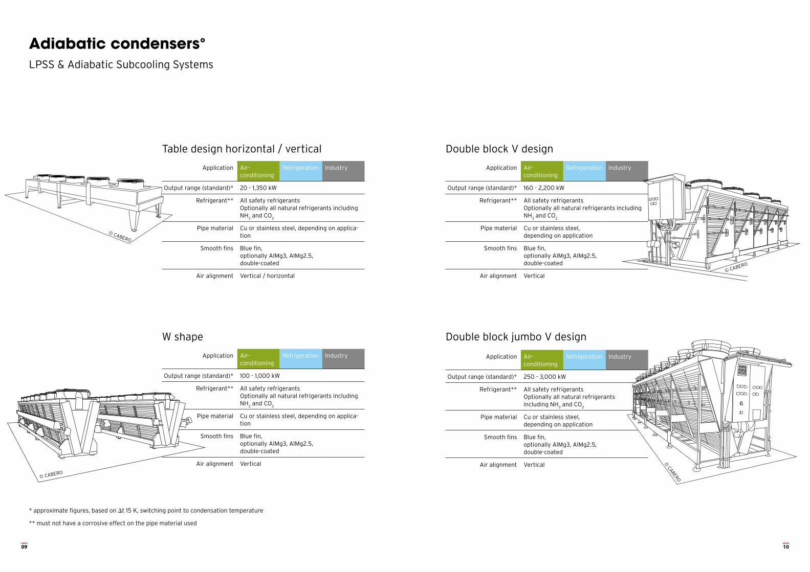
Application Air- conditioning
Refrigeration Industry
Output range (standard)* 20 - 1,350 kW
Refrigerant** All safety refrigerantsOptionally all natural refrigerants including NH
3 and CO
2
Pipe material Cu or stainless steel, depending on applica-tion
Smooth fins Blue fin, optionally AlMg3, AlMg2.5, double-coated
Air alignment Vertical / horizontal
Adiabatic condensers°LPSS & Adiabatic Subcooling Systems
Table design horizontal / vertical Double block V design
W shape Double block jumbo V design
Application Air- conditioning
Refrigeration Industry
Output range (standard)* 160 - 2,200 kW
Refrigerant** All safety refrigerantsOptionally all natural refrigerants including NH
3 and CO
2
Pipe material Cu or stainless steel, depending on application
Smooth fins Blue fin, optionally AlMg3, AlMg2.5, double-coated
Air alignment Vertical
Application Air- conditioning
Refrigeration Industry
Output range (standard)* 100 - 1,000 kW
Refrigerant** All safety refrigerantsOptionally all natural refrigerants including NH
3 and CO
2
Pipe material Cu or stainless steel, depending on applica-tion
Smooth fins Blue fin, optionally AlMg3, AlMg2.5, double-coated
Air alignment Vertical
Application Air- conditioning
Refrigeration Industry
Output range (standard)* 250 - 3,000 kW
Refrigerant** All safety refrigerantsOptionally all natural refrigerants including NH
3 and CO
2
Pipe material Cu or stainless steel, depending on application
Smooth fins Blue fin, optionally AlMg3, AlMg2.5, double-coated
Air alignment Vertical
* approximate figures, based on t 15 K, switching point to condensation temperature
** must not have a corrosive effect on the pipe material used
© CABERO
© CABERO
09 10
© CABERO
© CABERO
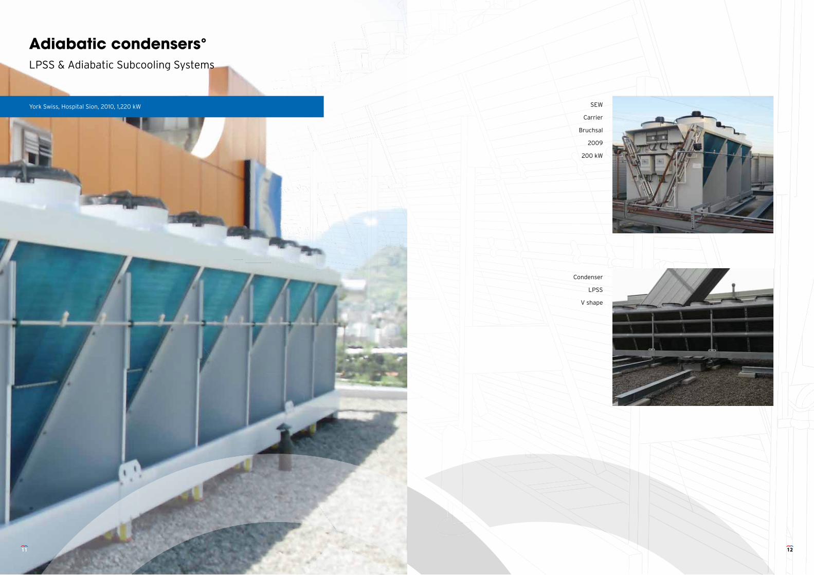
Adiabatic condensers°LPSS & Adiabatic Subcooling Systems
York Swiss, Hospital Sion, 2010, 1,220 kW SEW
Carrier
Bruchsal
2009
200 kW
Condenser
LPSS
V shape
11 12
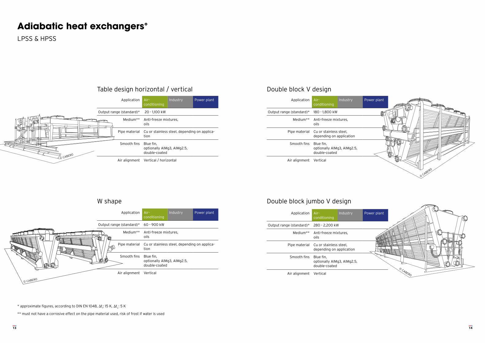
Adiabatic heat exchangers°LPSS & HPSS
Table design horizontal / vertical Double block V design
W shape Double block jumbo V design
Application Air- conditioning
Industry Power plant
Output range (standard)* 20 - 1,100 kW
Medium** Anti-freeze mixtures, oils
Pipe material Cu or stainless steel, depending on applica-tion
Smooth fins Blue fin, optionally AlMg3, AlMg2.5, double-coated
Air alignment Vertical / horizontal
Application Air- conditioning
Industry Power plant
Output range (standard)* 180 - 1,800 kW
Medium** Anti-freeze mixtures, oils
Pipe material Cu or stainless steel, depending on application
Smooth fins Blue fin, optionally AlMg3, AlMg2.5, double-coated
Air alignment Vertical
Application Air- conditioning
Industry Power plant
Output range (standard)* 60 - 900 kW
Medium** Anti-freeze mixtures, oils
Pipe material Cu or stainless steel, depending on applica-tion
Smooth fins Blue fin, optionally AlMg3, AlMg2.5, double-coated
Air alignment Vertical
Application Air- conditioning
Industry Power plant
Output range (standard)* 280 - 2,200 kW
Medium** Anti-freeze mixtures, oils
Pipe material Cu or stainless steel, depending on application
Smooth fins Blue fin, optionally AlMg3, AlMg2.5, double-coated
Air alignment Vertical
* approximate figures, according to DIN EN 1048, t1: 15 K, t
L: 5 K
** must not have a corrosive effect on the pipe material used, risk of frost if water is used
© CABERO
13 14
© CABERO
© CABERO
© CABERO
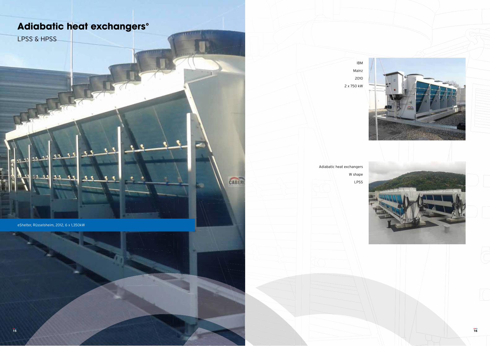
Adiabatic heat exchangers°LPSS & HPSS
eShelter, Rüsselsheim, 2012, 6 x 1,350kW
IBM
Mainz
2010
2 x 750 kW
Adiabatic heat exchangers
W shape
LPSS
15 16
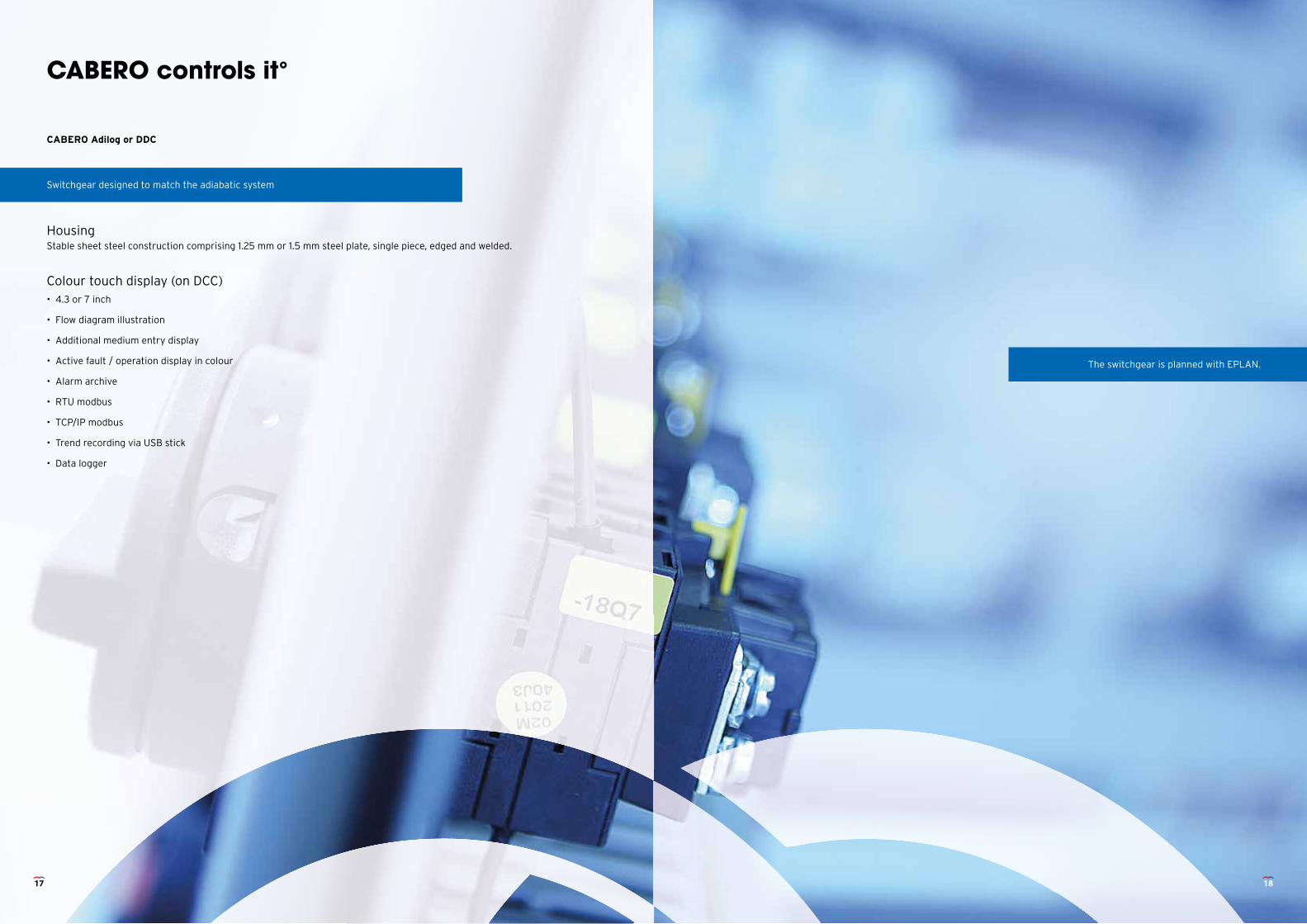
CABERO controls it°
CABERO Adilog or DDC
HousingStable sheet steel construction comprising 1.25 mm or 1.5 mm steel plate, single piece, edged and welded.
Colour touch display (on DCC)• 4.3 or 7 inch
• Flow diagram illustration
• Additional medium entry display
• Active fault / operation display in colour
• Alarm archive
• RTU modbus
• TCP/IP modbus
• Trend recording via USB stick
• Data logger
Switchgear designed to match the adiabatic system
The switchgear is planned with EPLAN.
17 18
Precisely controlled°Reliable operation thanks to the best technology and materials
Details• Central supply 400 V/3/50 Hz
• Control cabinet ventilation
• Pre-fuses for motor outlets wired to rail-mounted terminals
• Repair switch fi tted into front of control panel, wired in pairs, optionally individually
Optional special featuresEco-Boost: Function for switching off EC motors in standby in accordance with NAV (low voltage connection directive)
with dew point monitoring.
Bypass module: Allows manual control of fi eld equipment in manual mode without DDC.
Specifi cation of a 2nd working point from activation via PFC.
Control via potential-free contacts (PFC)• Regulation release
• Set point 2
• Night restriction
• Release of 2nd working point
• Manual drainage
Signals (PFC)• Operation of motors
• Adiabatic operation
• Drainage operation
• Collective fault
• Detailed individual signals via MOD BUS RTU or Ethernet TCP/IP
Switchable mains supply manual or automatic is optionally available.
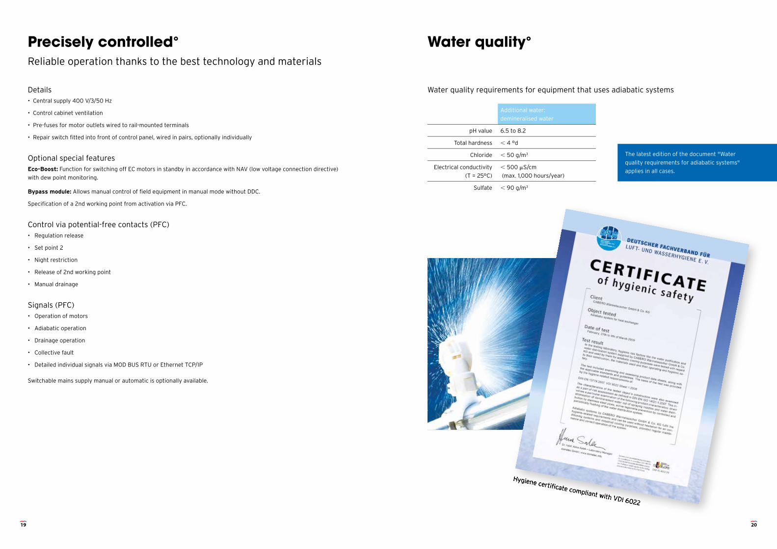
Water quality°
Water quality requirements for equipment that uses adiabatic systems
Hygiene certifi cate compliant with VDI 6022
Additional water:
demineralised water
pH value 6.5 to 8.2
Total hardness 4 °d
Chloride 50 g/m3
Electrical conductivity
(T = 25°C)
500 S/cm
(max. 1,000 hours/year)
Sulfate 90 g/m3
Hygiene certifi cate compliant with VDI 6022
The latest edition of the document "Water
quality requirements for adiabatic systems"
applies in all cases.
19 20
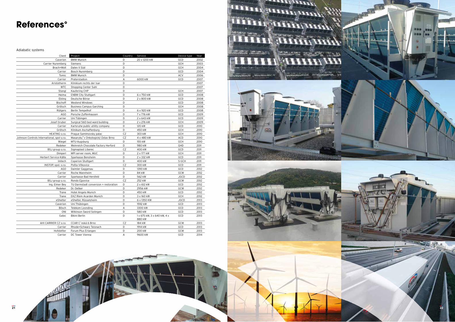
References°
Adiabatic systems
Client Project Country Service Device type Year
Caverion BMW Munich D 20 x 1200 kW GCD 2002
Carrier Nuremberg Siemens D GCH 2003
Brach+Moll Datev II Süd D GCH 2004
Carrier Bosch Nuremberg D GCD 2004
Tomic BMW Munich D ACV 2006
Carrier Praterstadion A 6000 kW GCD 2007
Aristotherm Klinikium rechts der Isar D 2007
WTC Shopping Center Suhl D 2007
Stangl Kaufering CHP D GCH 2007
Heima ENBW City Stuttgart D 6 x 750 kW GCD 2008
Ebling Deutsche Börse D 2 x 800 kW GCD 2008
Bischoff Westend Windows D GCD 2008
Grötsch Business Campus Garching D GCH 2008
Rütgers Berlin Tempelhof D 6 x 920 kW GCD 2008
AGO Porsche Zuffenhausen D 7 x 776 kW GCD 2009
Carrier Uni Tübingen D 2 x 643 kW GCD 2009
Josef Gruber Surgical 560-bed ward building D 2 x 276 kW GCH 2009
Carrier Karlsruhe public utility company D 120 kW GCD 2010
Grötsch Klinikum Aschaffenburg D 450 kW GCH 2010
HEATING s.r.o. Prague Samlmovsky palac CZ 303 kW GCH 2010
Johnson Controls International, spol s.r.o. Masaryku˚v Onkologický Ústav Brno CZ 4 x 480 kW ACD 2010
Wiegel MTU-Augsburg D 155 kW GCH 2010
Redeker Weinreich Chocolate Factory Herford D 980 kW GHD 2011
BSJ group s.r.o. Sigmaplast Liberec CZ 400 kW GCD 2011
Dimperl MPI server room, MUC D 2 x 177 kW GCH 2011
Herbert Service-Kälte Sparkasse Bensheim D 2 x 332 kW GCD 2011
Imtech Coperion Stuttgart D 400 kW S-GCH 2011
INSTOP, spol. s.r.o. Pošta Vítkovice CZ 300 kW GCD 2011
AGO Daimler Gaggenau D 1390 kW GCD 2012
Carrier Roche Mannheim D 84 kW GCW 2012
Carrier Sparkasse Bad Hersfeld D 562 kW JGCD 2012
BSJ group s.r.o. Rondo Ejpovice CZ 252 kW GCW 2012
Ing. Elmer Bey TU Darmstadt conversion + restoration D 2 x 612 kW GCD 2012
Redeker Dr. Oetker D 2956 kW GCW 2012
Trane Hotel Angelo Munich D 450 kW GCD 2012
Trane EKZ Riem Acarden Munich D 3 x 160 kW GCH 2012
eShelter eShelter, Rüsselsheim D 6 x 1350 KW JGCD 2013
Caverion Uni Thübingen D 1592 kW GCD 2013
Bösch Telekom Leonding A 3300 kW GCD 2013
ONI Wilkinson Sword Solingen D 580 kW GCD 2013
Gatec Bikini Berlin D 1 x 675 kW, 3 x 640 kW, 4 x 880 kW
GCD 2013
AHI CARRIER CZ s.r.o. CCAR Cˇeská 6 Brno CZ 184 kW GCW 2013
Carrier Rhode+Schwarz Teisnach D 1914 kW GCD 2013
Hofstetter Forum Plus Erlangen D 200 kW GCW 2013
Carrier DC Tower Vienna A 9600 kW GCD 2014
21 22
engineered to succeed
CABERO Wärmetauscher GmbH & Co.KG
Jesenwanger Str. 50 D-82284 Grafrath Germany
www.cabero.de