ADHESION OF AGGREGATE-BINDER SYSTEMS
65
MSc. Thesis Priya Darshini Cheyyar Nageswaran 2016, Delft ADHESION OF AGGREGATE-BINDER SYSTEMS
Transcript of ADHESION OF AGGREGATE-BINDER SYSTEMS

MSc. Thesis
Priya Darshini Cheyyar Nageswaran
2016, Delft
ADHESION OF AGGREGATE-BINDER SYSTEMS

ADHESION OF AGGREGATE-BINDER SYSTEMS
by
Priya Darshini Cheyyar Nageswaran
in partial fulfilment of the requirements for the degree of
Master of Science
in Structural engineering
at the Delft University of Technology,
to be defended publicly on Friday January 29, 2016 at 16:00 hrs.
Under the supervision of Graduation Committee:
Prof. dr. A. Scarpas Pavement engineering, CEG, TU Delft
Ir. A. Varveri Pavement engineering, CEG, TU Delft
Ir. L.J.M. Houben Pavement engineering, CEG, TU Delft
Ir. R. W. M. Naus Dura Vermeer
Dr. J. A. Poulis Adhesion Institute, AE, TU Delft

i
ACKNOWLEDGEMENT My sincere thanks to the members of my graduation committee, Prof. dr. A. Scarpas, ir. A.
Varveri, ir. L.J.M. Houben, ir. R. W. M. Naus, and dr. J. A. Poulis, for their continuous
support and guidance throughout my thesis work.
I would like to thank the Pavement Engineering laboratory technicians Ing. M.R. Poot and
Mr. J.W. Bientjes, without whom my graduation work would have never progressed.
I would also like to thank Mr. L.A.M. Smal and ir. S. A. Mohan from Dura Vermeer for their
insightful inputs which helped me in very many ways.
I wish to thank Mr. R.A. Penners from the Macro Mechanic laboratory and Ing. W. Verwaal
from Geoscience and engineering laboratory for their help.
It has always given me great pride to work in TU Delft with the support of Dura Vermeer for
this project.
Sincere thanks to all my friends and colleagues who has always helped me in every possible
way.
Finally, I thank my family for their unconditional love, support and encouragement.
Jai Shri Ram.
ii
ABSTRACT Adhesion is a difficult, but important phenomenon which needs to be addressed in the field of
pavement engineering. A strong adhesion between the constituents of pavement and between
the layers of the pavement is an indication of its durability. Many modern materials like
rubber, fibre, epoxy binder, adhesion promoter etc., are used as a replacement or addition to
the conventional bitumen and aggregate materials in pavement construction. The introduction
of these materials thus require a better understanding of their adhesive properties, which
influences to a great extent, the pavement performance. Since there are no standard tests
available to quantify adhesion in pavement engineering, the study aims at developing a
framework of easily implementable test procedure that can be used for the assessment of the
adhesive bond between the different materials used in pavement construction. This was
achieved by performing direct tension test on different types of aggregate-binder systems. As
the presence of moisture is a known factor that affects adhesion, in turn affecting performance
of the pavement, the study also concentrated towards this aspect. Three types of aggregates
(porphyry, diorite and sandstone), in combination with four different binders (bitumen
pen70/100, SBS polymer modified bitumen, polyurethane based binder and epoxy based
binder) and two adhesion promoters (Type a and b, with variation in curing time) were tested
in this study. They were subjected to low and high temperature and strain rates and the effect
of moisture on these materials were also investigated. It was found from this study that the
direct tension test was easily implementable, which could help the contractors and researchers
in quantifying the adhesion between the various aggregate-binder systems.
KEYWORDS: adhesion, bond strength, adhesion promoter, binder-aggregate interaction
iii
Contents ACKNOWLEDGEMENT .......................................................................................................... i
ABSTRACT ............................................................................................................................... ii
1. INTRODUCTION AND LITERATURE REVIEW .............................................................. 1
1.1 Introduction and research motivation ............................................................................... 1
1.2 Literature review .............................................................................................................. 3
1.2.1 Adhesion .................................................................................................................... 3
1.2.2 Adhesion theories ...................................................................................................... 4
1.2.3 Aggregate - bitumen adhesion ................................................................................... 6
1.2.4 Conclusion ............................................................................................................... 12
1.3 Approach and research methodology ............................................................................. 13
1.3.1 Research objectives ................................................................................................. 13
1.3.2 Research methodology ............................................................................................ 13
1.3.3 Thesis outline .......................................................................................................... 14
2. MATERIALS ....................................................................................................................... 15
2.1 Aggregates ...................................................................................................................... 15
2.1.1 Mineral composition ............................................................................................... 16
2.1.2 Moisture absorption ................................................................................................. 18
2.2 Binders ........................................................................................................................... 20
2.3 Adhesion promoters ....................................................................................................... 22
2.4 Combinations used for testing ........................................................................................ 22
3. DIRECT TENSION TEST ................................................................................................... 24
3.1 Sample preparation ......................................................................................................... 24
3.1.1 Aggregate cores preparation .................................................................................... 24
3.1.2 Assembling the stone columns and curing .............................................................. 24
3.2 Test setup and conditions ............................................................................................... 26
3.2.1. Moisture conditioning ............................................................................................ 27
iv
4. RESULTS AND ANALYSIS .............................................................................................. 27
4.1 Results from tests at dry condition ................................................................................. 28
4.1.1 Influence of aggregate type ..................................................................................... 28
4.1.2 Influence of binder type .......................................................................................... 31
4.1.3 Influence of adhesion promoters ............................................................................. 33
4.2 Results from tests after moisture conditioning ............................................................... 36
4.2.1 Influence of aggregate type ..................................................................................... 36
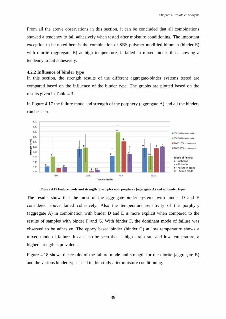
4.2.2 Influence of binder type .......................................................................................... 39
4.2.3 Influence of adhesion promoters ............................................................................. 41
4.3 Moisture susceptibility ................................................................................................... 43
4.3.1 Influence of aggregate type ..................................................................................... 44
4.3.2 Influence of binder type .......................................................................................... 46
4.3.3 Influence of adhesion promoters ............................................................................. 48
5. CONCLUSIONS AND RECOMMENDATIONS ............................................................... 50
5.1 Conclusions .................................................................................................................... 50
5.2 Recommendations .......................................................................................................... 51
REFERENCES ......................................................................................................................... 52
Chapter 1 Introduction and literature review
1
1. INTRODUCTION AND LITERATURE REVIEW
1.1 Introduction and research motivation Pavements are designed to carry the loads imposed on them due to vehicular and pedestrian
traffic. From the Roman roads to asphalt concrete, all types of pavements are a composite of
number of materials, traditionally: aggregates, bitumen, sand and fillers. The adhesion of the
pavement constituents is one of the important indicators of the durability of the pavement.
Adhesion in pavements occurs in the following levels:
• Adhesion between construction layers.
• Adhesion between traffic lanes when a discontinuous construction process is followed.
• Adhesion within the mixture between the components
Adhesive bonding is the gluing together of two different substrates through an intermediate
layer. Ideally, an adhesive bond is expected to withstand splitting, shearing, compression and
tension as wheels pass over the pavement surface. The major type of failures that occurs due
to poor adhesion between the constituents of asphalt pavements are ravelling and stripping.
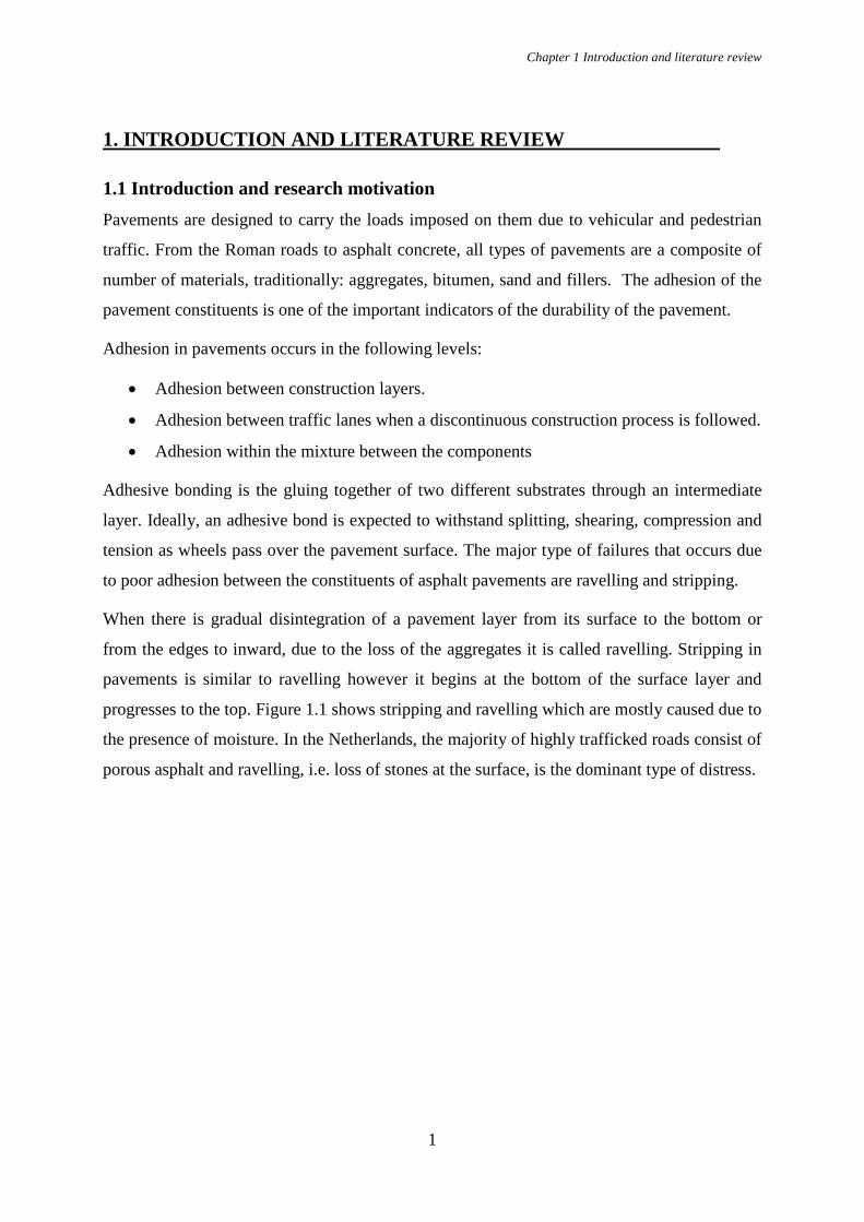
When there is gradual disintegration of a pavement layer from its surface to the bottom or
from the edges to inward, due to the loss of the aggregates it is called ravelling. Stripping in
pavements is similar to ravelling however it begins at the bottom of the surface layer and
progresses to the top. Figure 1.1 shows stripping and ravelling which are mostly caused due to
the presence of moisture. In the Netherlands, the majority of highly trafficked roads consist of
porous asphalt and ravelling, i.e. loss of stones at the surface, is the dominant type of distress.
Chapter 1 Introduction and literature review
2
Figure 1.1 Deteriorated pavements due to water induced damage: (a) ravelling caused by segregation and (b) potholes caused due to stripping Reprinted from Pavement Interactive (http://www.pavementinteractive.org/).
Apart from the durability demands, there is an increasing interest in minimizing the
environmental impact of pavement structures, mainly with respect to noise pollution. Road
traffic noise is a prominent source of noise pollution in Europe followed by aircraft and
railway noise. Exposure to high level of noise has adverse effects on human health and also
affects the economy. The major source of road traffic noise is that generated due to tyre-road
interaction. Construction of noise walls and banks are common methods used for noise
abatement. However, this is not possible at all locations due to lack of space and other
environmental constraints. Hence, during the last decade, the use of low–noise pavements has
gained a lot of attention. Generally, low-noise pavement surfaces have high porosity that
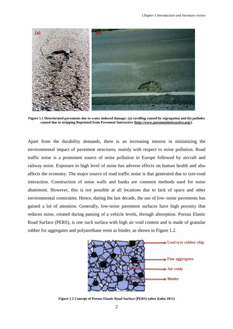
reduces noise, created during passing of a vehicle levels, through absorption. Porous Elastic
Road Surface (PERS), is one such surface with high air void content and is made of granular
rubber for aggregates and polyurethane resin as binder, as shown in Figure 1.2.
Figure 1.2 Concept of Porous Elastic Road Surface (PERS) (after Kubo 2011)
Used tyre rubber chip
Fine aggregates
Air voids
Binder
(a) (b)
Chapter 1 Introduction and literature review
3
Thus the use of unconventional materials like rubber, fiber, polyurethane etc., either as a
supplement or replacement for the conventional materials aiming at increasing strength and
durability and reducing noise, has gained a lot of importance. While the noise reduction
characteristics of PERS is very good, the major concerns arise due to the type of binder that
affects its cohesive and adhesive strength characteristics and the glues used for bonding PERS
with the base course. Introduction of these materials necessitates an understanding of their
adhesive properties and interaction with other commonly used materials, which finally affect
the performance of pavements to a great extent.
1.2 Literature review This section provides a general definition of adhesion and describes the major theories used to
explain adhesion. Following this, a literature review on aggregate-bitumen adhesion and the
effects of moisture, temperature and aging on the aggregate-binder systems is given. Finally,
ways of promoting adhesion of aggregate-binder systems are discussed and the main test
methods to evaluate adhesive bonding are described.
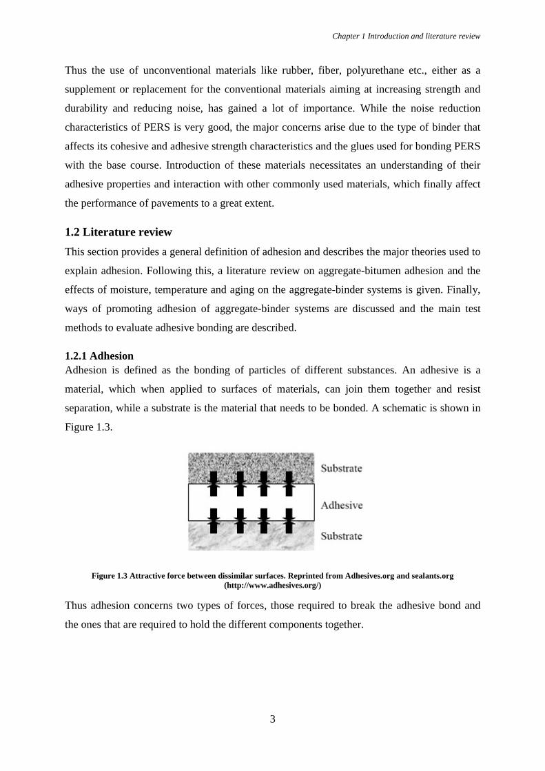
1.2.1 Adhesion Adhesion is defined as the bonding of particles of different substances. An adhesive is a
material, which when applied to surfaces of materials, can join them together and resist
separation, while a substrate is the material that needs to be bonded. A schematic is shown in
Figure 1.3.
Figure 1.3 Attractive force between dissimilar surfaces. Reprinted from Adhesives.org and sealants.org (http://www.adhesives.org/)
Thus adhesion concerns two types of forces, those required to break the adhesive bond and
the ones that are required to hold the different components together.

Chapter 1 Introduction and literature review
4
1.2.2 Adhesion theories To explain the mechanism of adhesion many theories have been postulated since the 1920s.
The main theories are explained in detail in this section.
1.2.2.1 Adsorption theory
The adsorption theory explains adhesion phenomenon based on wettability, spreading and
contact angle of the liquid drop of adhesive on the substrate. It postulates that whenever there
is contact between two materials at molecular level, there will be adhesion. The forces of
attraction between them are based on the chemical nature of surface of the materials, and
either physical adsorption (physisorption) or chemical adsorption (chemisorption) will occur
[1]. This theory addresses adhesion in terms of mere contact between substrate and adhesive.
Figure 1.4 Image showing adhesive and substrate contact angle where in (a) contact angle less than 90° and in (b)
contact angle greater than 90° (after Brewis and Mathieson 2001)
Based on this, contact angle is defined as the angle that a liquid creates with a solid surface
when both materials come in contact. Contact angle helps in quantifying the wetting of a
solid surface by a liquid. Wetting is the study of how a liquid deposited on a solid (or liquid)
substrate spreads out. If the contact angle is greater than 90°, as shown in Figure 1.4, the
wetting is said to be poor and if less than 90° it is said to be good. Spreading is said to occur
when the contact angle tends to zero. Thus if there is less roughness, wetting is reduced and
consequently the forces that form an adhesive bond are reduced, resulting in less adhesion.
1.2.2.2 Mechanical theory
This theory states that a good joint will result whenever a strong continuous film of a partly
embedded adhesive is formed in situ [1]. Here adhesion is said to occur by the penetration of
adhesives into the surface irregularities, like pores and cavities, on the surface on which it is
applied. Therefore, adhesion relies on the “mechanical interlocking” between the substrate
and adhesive, as shown in Figure 1.5, implying that rough surfaces provide higher adhesion
compared to a smooth surface.
Adhesive
Substrate
θ < 90° θ > 90° (a) (b)
Chapter 1 Introduction and literature review
5
Figure 1.5 Representation of mechanical theory of adhesion (after Mattson 2014)
It must also be noted that rough surfaces are solely not the reason for better adhesion. It might
also be due to other factors such as clean surfaces of substrate, formation of highly reactive
surface or increase in contact surface area [2].
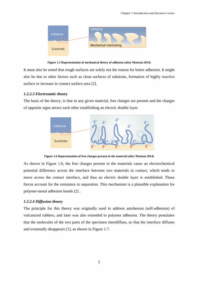
1.2.2.3 Electrostatic theory
The basis of the theory, is that in any given material, free charges are present and the charges
of opposite signs attract each other establishing an electric double layer.
Figure 1.6 Representation of free charges present in the material (after Mattson 2014)
As shown in Figure 1.6, the free charges present in the materials cause an electrochemical
potential difference across the interface between two materials in contact, which tends to
move across the contact interface, and thus an electric double layer is established. These
forces account for the resistance to separation. This mechanism is a plausible explanation for
polymer-metal adhesion bonds [2] .
1.2.2.4 Diffusion theory
The principle for this theory was originally used to address autohesion (self-adhesion) of
vulcanized rubbers, and later was also extended to polymer adhesion. The theory postulates
that the molecules of the two parts of the specimen interdiffuse, so that the interface diffuses
and eventually disappears [1], as shown in Figure 1.7.

Chapter 1 Introduction and literature review
6
Figure 1.7 Representation of diffusion theory of adhesion (after Mattson 2014)
The extent to which diffusion occurs depends on the nature of the materials and the bonding
conditions. Interdiffusion in polymers can take place only when the temperatures are above
their glass transition temperature [3]. Thermodynamic treatments of polymers, using Flory-
Huggins theory and practical studies with polymer blends, proved that mutual solubility is
rarely achieved thus restricting the applicability of theory of autohesion [1].
1.2.2.5 Weak Boundary Layer theory
A weak boundary is a cohesively weak layer in the interfacial region of an adhesive joint,
which may cause the joint itself to be weak, i.e. to fail at a low stress or with low fracture
energy [1]. In this case, even though failure seems to be in adhesion usually a cohesive break
of a weak boundary layer is the real event [4].
Figure 1.8 Representation of air bubbles and dust particles present near bonding surface. Reprinted from Research Gate (https://www.researchgate.net/)
A weak boundary layer can occur in the adhesive or adherent if any impurity is found near the
bonding surface, similar to those shown in Figure 1.8, and forms a weak attachment to the
substrate. It is this attachment that fails later. Surface treatments prior to adhesive bonding are
almost a prerequisite for success, since most of the surfaces are contaminated from the
environment exposure [1].
1.2.3 Aggregate - bitumen adhesion In asphalt mixtures, adhesive failure is considered to be one of the major characteristics that
are associated with the durability of the mixture. In asphalt mixtures, an adhesive bond is
formed when mastic (bitumen with fillers) comes in contact with the surface of the aggregate.
Dust particles
Air bubbles Substrate
Adhesive

Chapter 1 Introduction and literature review
7
Bitumen is composed of a number of functional groups which gets preferentially adsorbed on
the aggregates. The net adsorption tests performed by Curtis (1993) showed that there is a
large difference in the asphalt affinity that occurs between aggregates of different
mineralogical composition. The common trend observed is that sulfoxide and carboxylic acids
have greatest affinity for aggregates [5]. Surface energy measurements conducted by van Lent
(2013) showed that preferential adsorption of polar components on aggregate can be
explained with the help of difference in interaction energy of polar and non-polar components
present in bitumen. The adsorption of bitumen on the aggregate surface is more important
than the absorption process because, only the well adsorbed bitumen contributes to adhesion.
The absorbed bitumen locked in the pores of aggregates, is not available for forming bonds.
This absorption of bitumen to the aggregate is based on the viscosity of the bitumen and
porosity of the aggregate. In an experimental study by Mondal et al. (2012), tensile tests were
performed to determine the influence of bitumen thickness on the mode of failure at their
interface. The thickness of the bitumen film between two polished surfaces of aggregates
varied from 0.11 mm to 0.64 mm. The tensile load was applied at the rate of 1 mm/min and
the tests were carried out at 23 °C.
Figure 1.9 Dependence of cohesive or adhesive failure on bitumen film thickness (after Mondal et al. 2012)
It was observed that bitumen thickness influences adhesive failure of the bond between
aggregate and the bitumen, as shown in Figure 1.9. With the increase of the bitumen film
thickness the chances of adhesive failure also increased [6]. In a study performed by Bahia et
al. (2011), it was observed that another factor that influences the aggregate–bitumen bonding
is the stiffness of the bitumen. In this research, eight modified bitumen were prepared from
two commonly used bitumen in the United States and their iso-stiffness temperature was
determined.
Chapter 1 Introduction and literature review
8
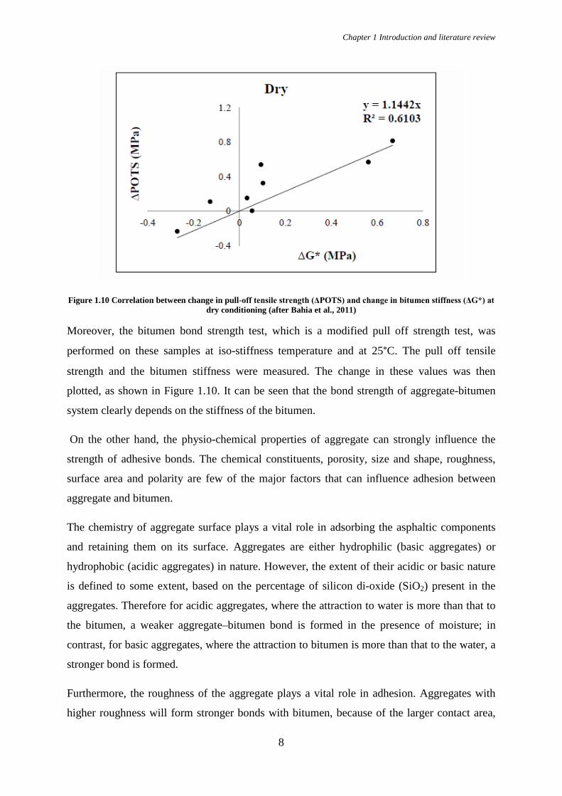
Figure 1.10 Correlation between change in pull-off tensile strength (ΔPOTS) and change in bitumen stiffness (ΔG*) at dry conditioning (after Bahia et al., 2011)
Moreover, the bitumen bond strength test, which is a modified pull off strength test, was
performed on these samples at iso-stiffness temperature and at 25°C. The pull off tensile
strength and the bitumen stiffness were measured. The change in these values was then
plotted, as shown in Figure 1.10. It can be seen that the bond strength of aggregate-bitumen
system clearly depends on the stiffness of the bitumen.
On the other hand, the physio-chemical properties of aggregate can strongly influence the
strength of adhesive bonds. The chemical constituents, porosity, size and shape, roughness,
surface area and polarity are few of the major factors that can influence adhesion between
aggregate and bitumen.
The chemistry of aggregate surface plays a vital role in adsorbing the asphaltic components
and retaining them on its surface. Aggregates are either hydrophilic (basic aggregates) or
hydrophobic (acidic aggregates) in nature. However, the extent of their acidic or basic nature
is defined to some extent, based on the percentage of silicon di-oxide (SiO2) present in the
aggregates. Therefore for acidic aggregates, where the attraction to water is more than that to
the bitumen, a weaker aggregate–bitumen bond is formed in the presence of moisture; in
contrast, for basic aggregates, where the attraction to bitumen is more than that to the water, a
stronger bond is formed.
Furthermore, the roughness of the aggregate plays a vital role in adhesion. Aggregates with
higher roughness will form stronger bonds with bitumen, because of the larger contact area,
Chapter 1 Introduction and literature review
9
that is available for bitumen to interlock. However too much of roughness will result in less
contact area for bitumen, resulting in weaker bonding. Angular aggregates are better for
proper interlocking of bitumen, but, too much angularity will provide less contact area,
resulting thus in poor bonding [7]. Also, porous aggregates lead to absorption of bitumen
(depending on its viscosity), thus facilitating adhesive bonding, since the pores that are on the
surface of the aggregates, increase their roughness and promote adhesion. Though, aggregates
with very high porosity can lead to the locking of bitumen in the pores, thus making it
unavailable for adhesion. Finally, dust particles on the aggregate surface prevent a direct
bitumen – aggregate bond, resulting thus in a weak bond formation.
1.2.3.1 Effect of moisture on adhesion
Water, in liquid or vapour form penetrates through pavement structures in various ways, such
as water seeping through cracks or porous pavements, water rising from subgrade etc. In the
presence of moisture the strength of the bond between bitumen and aggregates is
compromised and can cause stripping (loss of adhesion) related problems. Consequently, the
stiffness and the structural strength of the asphalt pavement is lost and the pavement can fail
prematurely.
Stripping can be explained through mechanisms such as detachment, displacement,
spontaneous emulsification and pore pressure. The presence of water in an asphalt mix may
lead to detachment, which is defined as the separation of an asphalt film from an aggregate
surface by a thin layer of water with no obvious break in the film [8]. Tarrer (1991) states that
when a stripping by detachment occurs there is complete loss of adhesion between bitumen
and the aggregates.
Another mechanism, by which stripping occurs is by displacement. In this case, water
replaces the bitumen from the aggregate surface. This may occur when the water penetrates
into the aggregate surface through a break in the asphalt film and is called stripping by
displacement [9]. It may also occur due to incomplete coating of the aggregate, pinholes
formed by dust in the binder or due to film rupture on the edges of the aggregate. Spontaneous
emulsification occurs when an inverted emulsion of water droplet forms in asphalt cement
[10]. Fromm (1974) states that water infiltrates into the aggregate in the form of droplets and
breaks the bond between asphalt and aggregate.
Alternative mechanism that can lead to loss of adhesive bond is pore pressure development.
Due to the loading on the pavement, the water in the air voids is compressed, thus increasing
the pressure in the asphalt films. This is known as stripping due to pore pressure. Moisture

Chapter 1 Introduction and literature review
10
cannot only cause a decrease in the bond strength, but is also capable of changing the mode of
failure from cohesive to adhesive which can be observed from the tests performed by Bahia et
al. (2011). This change in mode of failure was observed to be dependent on the conditioning
time. The various modified bitumen samples tested in this study were moisture conditioned in
tap water for 0, 6, 24, 48 and 96 hours. The effect of moisture conditioning time on the pull
off tensile strength of the aggregate–bitumen system (granite/limestone with different
bitumen) was determined, which suggested that the loss of adhesion increased with the
conditioning time.
1.2.3.2 Adhesion promoters
Adhesion promoters are chemicals that act as the interface between an organic polymer and
an inorganic substrate to enhance adhesion between the two materials [2] and produce a
strong adhesive bond structure. Adhesive promoters are applied as a pre-coat before the
application of the adhesive. In the field of pavement engineering, adhesion promoters are used
to form a strong bond between the bitumen and the aggregate, and moreover resist the
displacing effect of water. The use of adhesion promoters can also be made in combination
with additives which improve the asphalt binder characteristics. Silane-based adhesion
promoters have been successfully shown to promote adhesion between organic and inorganic
materials and to increase durability in wet environments [11]. The effectiveness of these
promoters is attributed to the fact that they act as a chemical bridge, where one part of the
molecule attaches to the substrate and another part bonds to the adhesive or polymer [3]. The
results can be consistent and reproducible when substrates are treated with silane adhesion
promotors, and if their preparation is done in a controlled manner, thus giving good bond
strength and durability. There are also amine-based adhesion promoters, which consist of long
hydrocarbon chains and amine functional groups, and are said to benefit bitumen-aggregate
systems [11]. The hydrocarbon groups react with the bitumen and the amine group with the
aggregates, thus increasing the wettability of the bitumen on the aggregate and result in strong
bond formation between them. Apart from improving the aggregate- bitumen interaction, the
amine-based adhesion promoters are also considered as an effective method for improving
water resistance.
1.2.3.3 Adhesion tests
There are a number of test methods to evaluate adhesion bond strength between two materials.
These tests can be based on thermodynamics, mechanics, spectroscopy, electrostatic and
Chapter 1 Introduction and literature review
11
electromagnetic theories etc. These tests try to investigate and explain adhesion based on the
different adhesion theories described previously.
In literature, there are a number of tests performed to investigate adhesion of binder-aggregate
systems. Considering that binder-aggregate interactions are strongly influenced by surface
chemistry of aggregate with respect to adsorption and stripping [12], Bhasin & Little (2009)
estimated the surface free energy components of aggregates using the micro calorimeter
method. They claimed that this method is a better choice compared to other methods, which
measures surface energy. The authors concluded that the heat of immersion of aggregates in
asphalt binders, at mixing temperatures, delivers a direct measure of the total energy of
adhesion between asphalt binders and aggregates.
Also, mechanical tests were employed to study adhesion in asphalt mixtures. Bitumen Bond
Strength tests were performed by Bahia et al. (2011) measured the effects of moisture
conditioning time and bond strength of bitumen-aggregate systems. In this test, the results
were classified as adhesive or cohesive failure by the assumption that when more than 50% of
the aggregate is exposed, then it is an adhesive failure else cohesive. In a study performed by
Tang et al. (2001), tensile tests were done for brittle coatings on ductile substrates (cohesive
failure of paint occurred before adhesive failure) and measured the adhesion between
polypropylene blends and paints. Furthermore, Silva et al. (2003), carried out tensile tests to
evaluate the influence of the mastic binder content on the strength of the bond between mastic
and aggregates. The study concluded that mechanical tests simulate correctly the existent
phenomenon.
Below, few of the standardized tests that are performed to determine adhesion are shown:
• Knife Test (ASTM D6677) is performed to assess the adhesion of coating films to
substrate using a knife. The cuts are made into the coating on the substrate in the form
of an X mark, and at the vertex it is attempted to remove the (or lift up) the coating.
The difficulty to remove the coating and the size of the removed coating are the
parameters considered to assess the adhesion.
• Tape Test (ASTM D3359) helps in assessing the adhesion of coating films to metallic
substances by applying and removing pressure-sensitive tape cuts made in the film.
There are two types in this test. In the first type of test an X cut is made with sharp
knife into the coating on the substrate and the tape is placed on the centre of the
intersection of the cuts and then removed rapidly. Then the cut area is now
Chapter 1 Introduction and literature review
12
investigated for removal of the coating and then rated accordingly. In the second type
of test a cross-hatch patter in made using a special cutter and then the tape is applied
on the area and pulled off. The cut area is then investigated and rated accordingly.
This method is used fir coatings with thickness less than 125 µm.
• Scrape Test (ASTM D2197) is used to determine the adhesion of organic coatings
when applied to smooth, flat panel surfaces. Adhesion is determined by pushing the
coated panels beneath a rounded stylus that is loaded in increasing amounts until the
coating is removed from the substrate using a balanced-beam scrape adhesion tester.
• Pull off test (ASTM D4541 and ISO 4624) evaluates the pull-off strength of a coating
system from a metal substrate. It can be a single or multi-coat system. In this method a
loading fixture is attached by an adhesive a coating and with a pull-off adhesion tester,
loading is increasingly applied to the surface until the loading fixture is pulled off. The
force required to pull off the fixture gives the tensile strength and failure will occur
along the weakest plane.
• Peel Test (ASTM D1876) gives information about the bond strength between the
adhesive and the substrate. A T- type specimen is made out of the adhesive and
substrate and one end of the specimen is left unbonded. This side is pulled at a
constant speed by a tensile testing machine. This test is used when a flexible material
is bonded to a rigid substrate. After the test a load versus position graph is plotted and
the force to be considered for strength calculation, is ideally, the peak force obtained
in the plot.
There tests help in evaluating the ability of a coating system to withstand the stresses of
fabrication. Other tests also exist that aim to determine adhesion between organic coatings to
plastic substances and factory-applied complex coating to steel substrates.
1.2.4 Conclusion The following conclusions were made from the literature review:
• Adhesive failure in asphalt mix can be considered as the separation of bitumen (with
fillers) from the aggregate.
• Aggregate properties are said to have more impact on the adhesion compared to the
bitumen properties.

Chapter 1 Introduction and literature review
13
• The adhesion between the bitumen-aggregate systems results from a combination of a
number of mechanisms, such as thermodynamical, mechanical and physicochemical.
There is not a single dominant mechanism through which adhesion can be defined.
• Moisture has adverse effects on the adhesion between aggregate-bitumen systems. The
choice of a hydrophobic aggregate or, the use of chemical additives in bitumen can
help in minimizing such degradation.
• Use of the right adhesion promoter, cannot only help in improving the bond strength
between the aggregate and the bitumen, but also improve the water resistance of the
bond.
• There are no standardized testing procedure for quantifying adhesion between
aggregate and bitumen. Adhesive bonds can be evaluated by studying adhesion
failures through different methods, like chemical, mechanical, thermodynamical or
electrostatic tests.
1.3 Approach and research methodology This section elaborates on the aim of this research, the methodology employed in meeting the
target set. Also, the outline of this research is briefly presented.
1.3.1 Research objectives This study aims at developing a framework of easily implementable test procedures that can be
used for the assessment and ranking of the quality of the adhesive bond between the pavement
materials, both conventional and unconventional. A second objective is to obtain
insight/develop an understanding of which and to what extent specific material properties (or
aggregate properties) affect the final bonding characteristics This information can be used by
contractors to develop boundaries in which properties of raw materials may vary in practice. It
has been acknowledged that the presence of moisture influences the adhesion between the
aggregate – bitumen system and hence this study will take into account the effects of moisture
on the adhesion between materials for a more wholesome and accurate indication of the
bonding quality.
1.3.2 Research methodology Since adhesion can be explained with the help many theories, quantifying the adhesive bond
in aggregate-binder systems through one single test method is a challenging task. However, an
easily implementable test method to quantify adhesion will definitely give an idea about the
trend in which the aggregate-binder system behaves. With the trend information on these

Chapter 1 Introduction and literature review
14
systems, it becomes easier for researchers or contractors to predict the behaviour of the
materials when used together. This in turn can also help in predicting the behaviour of the
pavement mixture consisting of tested materials.
An elaborate study on adhesion and the research carried out so far in the field of pavement
engineering on adhesion was done. It was observed that there are many ways to determine
adhesive bond strength, but no standard method to do this. Keeping in mind the goals that are
to be achieved, it was decided to perform mechanical tests on the adhesion of aggregate-
binder systems. Direct tension test on such systems were carried out at high and low
temperature and strain rates. The tests were performed on samples at dry conditions, as well
as on samples that were moisture conditioned in order to study the effect of moisture on
adhesion of aggregate-binder systems. The results from these tests were then analysed and
conclusions and recommendations were made for the enhancement of adhesion in these
systems and also for the improvement of the test method.
1.3.3 Thesis outline
This thesis consists of five chapters that are organized as follows:
Chapter 1 gives a general introduction on the topic of this thesis, an overview of adhesion
theories, and studies conducted so far on the aggregate-binder systems and the effect of
moisture on adhesion. It also gives the motivation and the objectives for this study.
Chapter 2 provides the specifics about the materials tested in this study.
Chapter 3 describes the sample preparation and testing conditions under which the direct
tension test was carried out.
In chapter 4, the results from the tests conducted are given and discussed in detail.
Finally, chapter 5 provides the conclusions that can be derived from the study and
recommendations for future research.
Chapter 2 Materials
15
2. MATERIALS In this chapter the materials used in this study namely, the aggregates, binders and adhesion
promoters are described. Below, the characteristics and the combinations of the materials are
given.
2.1 Aggregates Aggregates accounts for up to 96% of Hot Mix Asphalt (HMA), by volume. They are also
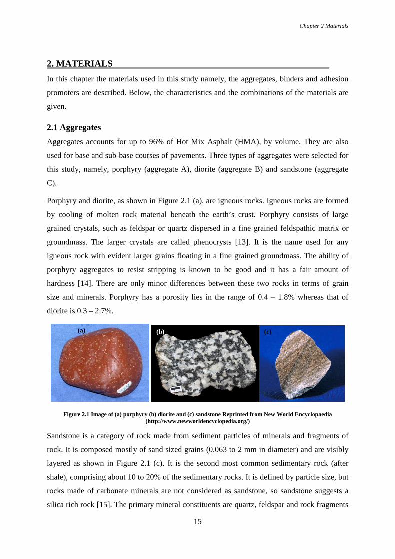
used for base and sub-base courses of pavements. Three types of aggregates were selected for
this study, namely, porphyry (aggregate A), diorite (aggregate B) and sandstone (aggregate
C).
Porphyry and diorite, as shown in Figure 2.1 (a), are igneous rocks. Igneous rocks are formed
by cooling of molten rock material beneath the earth’s crust. Porphyry consists of large
grained crystals, such as feldspar or quartz dispersed in a fine grained feldspathic matrix or
groundmass. The larger crystals are called phenocrysts [13]. It is the name used for any
igneous rock with evident larger grains floating in a fine grained groundmass. The ability of
porphyry aggregates to resist stripping is known to be good and it has a fair amount of
hardness [14]. There are only minor differences between these two rocks in terms of grain
size and minerals. Porphyry has a porosity lies in the range of 0.4 – 1.8% whereas that of
diorite is 0.3 – 2.7%.
Figure 2.1 Image of (a) porphyry (b) diorite and (c) sandstone Reprinted from New World Encyclopaedia (http://www.newworldencyclopedia.org/)
Sandstone is a category of rock made from sediment particles of minerals and fragments of
rock. It is composed mostly of sand sized grains (0.063 to 2 mm in diameter) and are visibly
layered as shown in Figure 2.1 (c). It is the second most common sedimentary rock (after
shale), comprising about 10 to 20% of the sedimentary rocks. It is defined by particle size, but
rocks made of carbonate minerals are not considered as sandstone, so sandstone suggests a
silica rich rock [15]. The primary mineral constituents are quartz, feldspar and rock fragments
(a) (b) (c)

Chapter 2 Materials
16
with a porosity of 3%. Sandstone is said to have good resistance for stripping and fair amount
of hardness in terms of its desirability in a HMA and is thus commonly used in asphalt
mixtures as aggregate [14].
2.1.1 Mineral composition The mineralogical composition of aggregates affects the surface texture and their affinity to
bond, which in turn affects the adhesion between aggregates and binder. An X- Ray
Fluorescence (XRF) analysis was carried out to determine the mineralogical composition of
the aggregates.
XRF is a non-destructive analytical technique, which uses interaction of X-rays with a
material to identify and quantify the elements and compounds present in the material. The
samples are energized by irradiation with X-rays, resulting in the emission of fluorescent X-
rays with discrete energies characteristic of the elements present. When atoms in the sample
are bombarded with X- rays, the electrons are ejected from the inner shells of the atom as
illustrated in Figure 2.2. To fill this newly created vacant position, an electron from the outer
shell drops down and makes the atom stable. When this happens, the energy produced in the
form of X-rays are emitted which is known as fluorescent radiation. Each element is said to
have a unique X-ray signature on detection of which the composition of the sample can be
known.
Figure 2.2 Representation of the principle of XRF. Reprinted from Bruker (https://www.bruker.com/)
For the measurements, the aggregates were milled to powders containing particles of size less
than 200 µm. These powders were then used in the XRF spectrometer to determine the
constituents of the aggregates. The compounds present in the aggregates, used in this study,
are given in Table 2.1.
Chapter 2 Materials
17
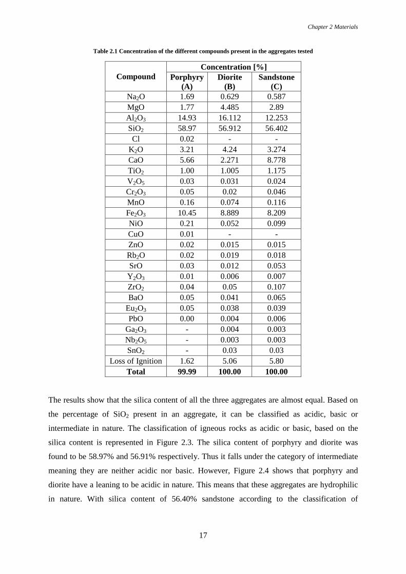
Table 2.1 Concentration of the different compounds present in the aggregates tested
Compound Concentration [%]
Porphyry (A)
Diorite (B)
Sandstone (C)
Na2O 1.69 0.629 0.587 MgO 1.77 4.485 2.89 Al2O3 14.93 16.112 12.253 SiO2 58.97 56.912 56.402 Cl 0.02 - -
K2O 3.21 4.24 3.274 CaO 5.66 2.271 8.778 TiO2 1.00 1.005 1.175 V2O5 0.03 0.031 0.024 Cr2O3 0.05 0.02 0.046 MnO 0.16 0.074 0.116 Fe2O3 10.45 8.889 8.209 NiO 0.21 0.052 0.099 CuO 0.01 - - ZnO 0.02 0.015 0.015 Rb2O 0.02 0.019 0.018 SrO 0.03 0.012 0.053 Y2O3 0.01 0.006 0.007 ZrO2 0.04 0.05 0.107 BaO 0.05 0.041 0.065
Eu2O3 0.05 0.038 0.039 PbO 0.00 0.004 0.006
Ga2O3 - 0.004 0.003 Nb2O5 - 0.003 0.003 SnO2 - 0.03 0.03
Loss of Ignition 1.62 5.06 5.80 Total 99.99 100.00 100.00
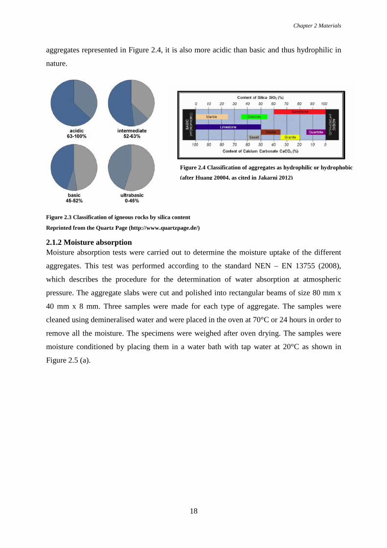
The results show that the silica content of all the three aggregates are almost equal. Based on
the percentage of SiO2 present in an aggregate, it can be classified as acidic, basic or
intermediate in nature. The classification of igneous rocks as acidic or basic, based on the
silica content is represented in Figure 2.3. The silica content of porphyry and diorite was
found to be 58.97% and 56.91% respectively. Thus it falls under the category of intermediate
meaning they are neither acidic nor basic. However, Figure 2.4 shows that porphyry and
diorite have a leaning to be acidic in nature. This means that these aggregates are hydrophilic
in nature. With silica content of 56.40% sandstone according to the classification of
Chapter 2 Materials
18
aggregates represented in Figure 2.4, it is also more acidic than basic and thus hydrophilic in
nature.
Figure 2.3 Classification of igneous rocks by silica content
Reprinted from the Quartz Page (http://www.quartzpage.de/)
2.1.2 Moisture absorption Moisture absorption tests were carried out to determine the moisture uptake of the different
aggregates. This test was performed according to the standard NEN – EN 13755 (2008),
which describes the procedure for the determination of water absorption at atmospheric
pressure. The aggregate slabs were cut and polished into rectangular beams of size 80 mm x
40 mm x 8 mm. Three samples were made for each type of aggregate. The samples were
cleaned using demineralised water and were placed in the oven at 70°C or 24 hours in order to
remove all the moisture. The specimens were weighed after oven drying. The samples were
moisture conditioned by placing them in a water bath with tap water at 20°C as shown in
Figure 2.5 (a).
Figure 2.4 Classification of aggregates as hydrophilic or hydrophobic
(after Huang 20004, as cited in Jakarni 2012)

Chapter 2 Materials
19
Figure 2.5 (a) Aggregates being conditioned in water bath at 20 °C and (b) one of the aggregates being weighed in a weighing scale
After 48 hours in the bath, the samples were taken out of the bath, quickly wiped with a damp
cloth and weighed as shown in Figure 2.5 (b), within one minute. Then, they were immersed
again in water and weighed every 24 hours until a constant weight of the specimen was
reached. The result of the last weighing was considered the weight of the saturated specimen.
The water absorption at atmospheric pressure was then calculated using the formula,
𝐴𝐴𝑏𝑏 =𝑚𝑚𝑠𝑠 − 𝑚𝑚𝑑𝑑
𝑚𝑚𝑑𝑑
(1)
, where 𝐴𝐴𝑏𝑏 is water absorption at atmospheric pressure in %
𝑚𝑚𝑠𝑠 is weight of the saturated specimen in g and
𝑚𝑚𝑑𝑑 is the weight of the dry specimen in g.
(a) (b)

Chapter 2 Materials
20
Figure 2.6 Moisture uptake over condition time for all aggregate types
The calculated moisture absorption for aggregates A, B and C is then plotted over time, as
shown in Figure 2.6. After the weight increase reached an equilibrium, the moisture
absorption values were calculated based on equation (1) are given in the Table 2.2.
Table 2.2 Moisture absorption values of the aggregates
Aggregate Moisture Absorption (%) A 0.18 B 0.36 C 0.20
It is evident from the results that diorite absorbs more moisture followed by sandstone and
porphyry.
As we observed from the results of XRF, all three aggregates has almost equal amount of
silica content. However, the discrepancy in the moisture absorption can be explained based on
the porosity. Diorite and sandstone has higher porosity range than porphyry.
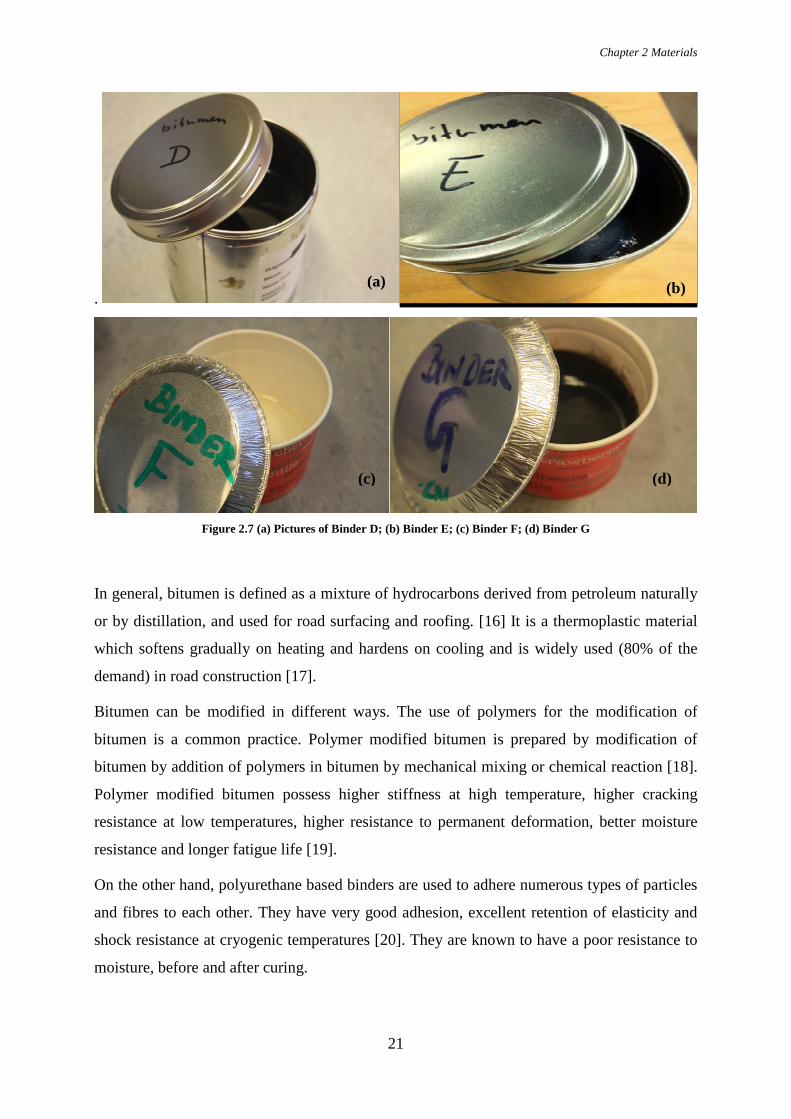
2.2 Binders In this study, four types of binders were used, namely, PEN 70/100 bitumen (binder D), SBS
polymer modified bitumen (binder E), a polyurethane based binder (binder F) and an epoxy
based binder (binder G). The binders are shown in Figure 2.7.
0,0000
0,0500
0,1000
0,1500
0,2000
0,2500
0,3000
0,3500
0,4000
0,4500
0 10 20 30 40
Moi
stur
e up
take
[%]
Time [days]
Porfier (A)
Diorite (B)
Sandstone (C)
Chapter 2 Materials
21
.
Figure 2.7 (a) Pictures of Binder D; (b) Binder E; (c) Binder F; (d) Binder G
In general, bitumen is defined as a mixture of hydrocarbons derived from petroleum naturally
or by distillation, and used for road surfacing and roofing. [16] It is a thermoplastic material
which softens gradually on heating and hardens on cooling and is widely used (80% of the
demand) in road construction [17].
Bitumen can be modified in different ways. The use of polymers for the modification of
bitumen is a common practice. Polymer modified bitumen is prepared by modification of
bitumen by addition of polymers in bitumen by mechanical mixing or chemical reaction [18].
Polymer modified bitumen possess higher stiffness at high temperature, higher cracking
resistance at low temperatures, higher resistance to permanent deformation, better moisture
resistance and longer fatigue life [19].
On the other hand, polyurethane based binders are used to adhere numerous types of particles
and fibres to each other. They have very good adhesion, excellent retention of elasticity and
shock resistance at cryogenic temperatures [20]. They are known to have a poor resistance to
moisture, before and after curing.
(b)
(c) (d)
(a)

Chapter 2 Materials
22
Similarly, epoxy based binders make excellent structural adhesives because of wide versatility
and basic adhesive qualities of epoxies [20]. They form strong bonds to most materials, in
addition to excellent chemical resistance and cohesive strength.
2.3 Adhesion promoters Adhesion promoters are used to improve the interaction between the binder and the aggregate
surface. In this study, two types of adhesion promoters were chosen namely, adhesion
promoters J and K. These adhesion promoters are a mix of two liquid components, mixed
together in a specific ratio to form the required adhesion promoter. The main difference
between the two is that adhesion promoter J is not required to dry after application to the
substrate, whereas adhesion promoter K must cure for 24 hours after application to the
substrate.
2.4 Combinations used for testing The above mentioned materials, i.e., aggregates, binders and adhesion promoters were tested
in various combinations. Table 2.3 gives the codes used for the presentation of each material,
while Table 2.4 shows the material combinations used for testing based on the aggregate type.
Table 2.3 Sample codes and their description
Sample code Type Name A Aggregate Porphyry B Aggregate Diorite C Aggregate Sandstone D Binder Bitumen (PEN 70/100) E Binder SBS Polymer modified binder F Binder Polyurethane based binder G Binder Epoxy based binder J Adhesion promoter Type a (no curing required) K Adhesion promoter Type b (requires curing)

Chapter 2 Materials
23
Table 2.4 Combinations used for testing based on aggregate type.
Aggregate A Aggregate B Aggregate C ADA BDB -
AEA BEB CEC
AFA BFB CFC
AGA BGB CGC
AJFJA BJFJB CJFJC
AKFKA BKFKB CKFKC

Chapter 3 Direct Tension Test
24
3. DIRECT TENSION TEST The direct tension test was the method used to investigate the strength between the aggregate
and the binder. In this chapter the test method, sample preparation and the environmental
conditions at which the direct tension test was carried out are explained in detail.
3.1 Sample preparation For the direct tension test, cylindrical samples were used with a diameter of 7.8 mm and a
total height of 20.015 mm, as shown in Figure 3.2. Each sample consisted of two aggregate
cores, with a height of 10 mm, glued together by the binder. The thickness of the binder was
15 µm. The detailed procedure for the sample preparation is given below.
3.1.1 Aggregate cores preparation Aggregate slabs of height 11 – 15 mm were used to obtain the aggregate cores. Each slab had
one side polished and the other sandblasted. Sandblasting was done to increase the surface
roughness of the aggregate, leading thus to a larger surface area per unit mass, resulting in
stronger adhesive bonding between the binder and the aggregate [21]. To make a cylindrical
core with a diameter of 7.8 mm, the slabs were cored using a custom made drill of 8mm
diameter (outer). Once the cores were obtained, they were polished (on the already polished
side) to obtain a uniform height of 10 mm and to make sure that the samples were straight.
3.1.2 Assembling the stone columns and curing The aggregate cores were cleaned using demineralised water to get rid of the impurities on the
surface of the aggregate and heated in the oven at 175°C for 30 minutes to remove any
remaining moisture.
Sample preparation was made by means of a Dynamic Shear Rheometer (DSR – EC Twist
502) in order to be able to accurately control the binder thickness. The aggregate cores were
first mounted on the holders available with the setup. The bottom holder was fixed, whereas
the top holder was free to move up and down in the setup. Once the aggregate cores were set
in place, the zero gap was determined using the software. It was then ensured that the
aggregate cores were straight and centred. The gap was then increased to 25 mm so as to
place a small drop of binder on the bottom stone, and the required binder thickness was
reached gradually in a number of steps (1mm - 50 µm - 25 µm - 15 µm). This ensured the
thickness of the binder was precise and that there was not much stress on the binder during
sample preparation. After having achieved the required thickness, the excess binder was

Chapter 3 Direct Tension Test
25
trimmed off, using a heated knife. The Figure 3.1 shows the clamping of aggregate cores and
their final positioning and Figure 3.2 shows the final geometry of the sample used in this
study.
Figure 3.1 (a) Aggregate cores clamped in their holders before placing binder; (b) Aggregate cores positioned to final thickness
Figure 3.2 Final stone column (Sample)
During sample preparation, the temperature in the DSR chamber varied for the different
binder types. For the bituminous binders, i.e. binder D and E, the temperature was set to 60 to
70 °C, so that the binder does not become stiff and prevent the stones from reaching the
required gap (15 µm).
For the polyurethane and epoxy based binders F and G a different approach was used. These
binders are quite viscous at room temperature and become less viscous upon cooling, thus
(a) (b)
Chapter 3 Direct Tension Test
26
making it convenient for sample preparation. So binders F and G were cooled down to 5 °C
before they were used for sample preparation.
For the samples prepared using the adhesion promoters, the promoters had to be applied on
the aggregate surface. The agents were scaled suing the sides of a knife to obtain a flat
surface. Adhesion promoter K was applied on the aggregate cores and left to dry for 24 hours
before applying the binder (according to the manufacturer’s instructions), whereas the binder
was applied directly after the application of adhesion promoter J.
The total curing time of the sample was 14 days at room temperature (20 – 25 °C), except for
the samples with binders D and E, which had to be cured at a temperature of 5 - 15°C and
hence were cured at 11°C.
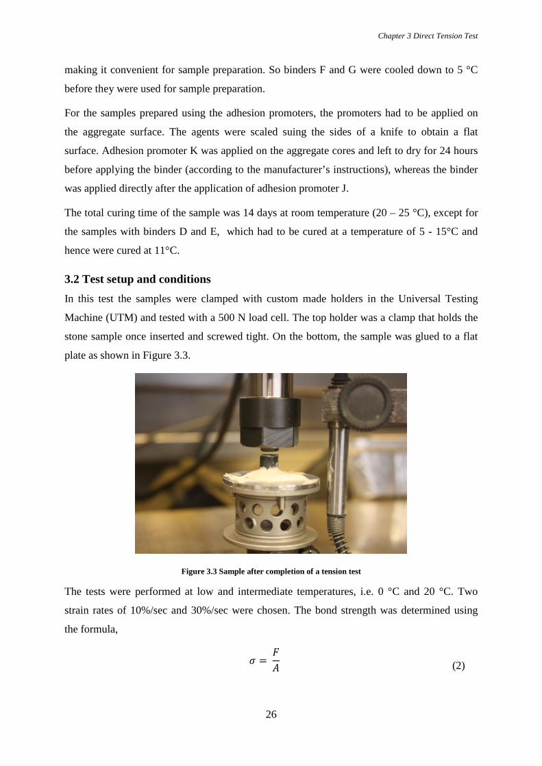
3.2 Test setup and conditions In this test the samples were clamped with custom made holders in the Universal Testing
Machine (UTM) and tested with a 500 N load cell. The top holder was a clamp that holds the
stone sample once inserted and screwed tight. On the bottom, the sample was glued to a flat
plate as shown in Figure 3.3.
Figure 3.3 Sample after completion of a tension test
The tests were performed at low and intermediate temperatures, i.e. 0 °C and 20 °C. Two
strain rates of 10%/sec and 30%/sec were chosen. The bond strength was determined using
the formula,
𝜎𝜎 = 𝐹𝐹𝐴𝐴
(2)

Chapter 3 Direct Tension Test
27
, where 𝜎𝜎 is the bond strength in N/mm2
𝐹𝐹 is the load at failure in N and
𝐴𝐴 is the surface area of the cylindrical sample in mm2
To investigate moisture susceptibility, the samples were tested at two different conditions
after the curing time of 14 days. For testing at dry conditions, the samples were kept at the
testing temperatures of 0 °C and 20 °C. For the moisture conditioned state, the samples were
exposed to moisture, as described in the following section.
3.2.1. Moisture conditioning To determine the influence of moisture on the aggregate-binder adhesion, the samples were
moisture conditioned for 72 hours in a water bath at 20°C. The samples were placed in the
water in such a way that the interface between the aggregate and the binder was at least 1 –
2mm above the water surface, as shown in Figure 3.4. This was to ensure that water can reach
the interface only through the aggregate and making the failure potentially adhesive [22].
Figure 3.4 Sample placed in water for moisture conditioning
Thus each sample was tested twice at the two different temperatures and strain rate, thus
making it four tests for one sample. Since the samples had to be tested at dry state and after
moisture conditioning, in total eight tests were performed on every combination used in this
study.

Chapter 4 Results & Analysis
27
4. RESULTS AND ANALYSIS In this chapter the results from the direct tension test will be discussed in detail. These tests
were performed at two different temperatures namely, 0 °C and 20 °C and at two different
strain rates of 10%/s and 30%/s. In addition to tests performed at dry condition, to examine
the influence of moisture, the samples were moisture conditioned for 72 hours and later tested
at the temperatures and strain rates mentioned above. The tests were performed on various
aggregate-binder combinations mentioned in Table 2.4. Specifically, in this study, three types
of aggregates namely, porphyry (aggregate A), diorite (aggregate B) and sandstone (aggregate
C) were used. These aggregates were used in combination with four types of binders i.e., pen
70/100 bitumen (binder D), polymer modified bitumen (binder E), polyurethane based binder
(binder F) and an epoxy based binder (binder G). Finally, two types of adhesion promoters
were chosen in this study namely, adhesion promoter J (type a, no curing before adding
binder) and K (type b, should be cured for 24 hours before adding binder).
To analyse the mode of failure of the samples, a digital microscope with a magnification
range of 10x to 200x with a high resolution (9.0 megapixel) was used. In this way, the two
failure modes namely, adhesive and cohesive, as shown in Figures 4.1 and 4.2 respectively,
were identified.
Figure 4.1 Adhesive mode of failure: Sample after failure as seen through the microscope (a) Top half of the sample with the binder completely adhered to the surface (b) Bottom half of the same sample with no
traces of binder on it.
(a) (b)
Sample 1 Sample 1
Chapter 4 Results & Analysis
28
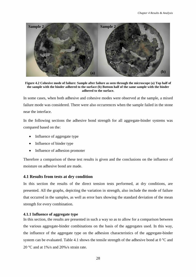
Figure 4.2 Cohesive mode of failure: Sample after failure as seen through the microscope (a) Top half of the sample with the binder adhered to the surface (b) Bottom half of the same sample with the binder
adhered to the surface.
In some cases, when both adhesive and cohesive modes were observed at the sample, a mixed
failure mode was considered. There were also occurrences when the sample failed in the stone
near the interface.
In the following sections the adhesive bond strength for all aggregate-binder systems was
compared based on the:
• Influence of aggregate type
• Influence of binder type
• Influence of adhesion promoter
Therefore a comparison of these test results is given and the conclusions on the influence of
moisture on adhesive bond are made.
4.1 Results from tests at dry condition In this section the results of the direct tension tests performed, at dry conditions, are
presented. All the graphs, depicting the variation in strength, also include the mode of failure
that occurred in the samples, as well as error bars showing the standard deviation of the mean
strength for every combination.
4.1.1 Influence of aggregate type In this section, the results are presented in such a way so as to allow for a comparison between
the various aggregate-binder combinations on the basis of the aggregates used. In this way,
the influence of the aggregate type on the adhesion characteristics of the aggregate-binder
system can be evaluated. Table 4.1 shows the tensile strength of the adhesive bond at 0 °C and
20 °C and at 1%/s and 20%/s strain rate.
(a) (b)
Sample 2 Sample 2
Chapter 4 Results & Analysis
29
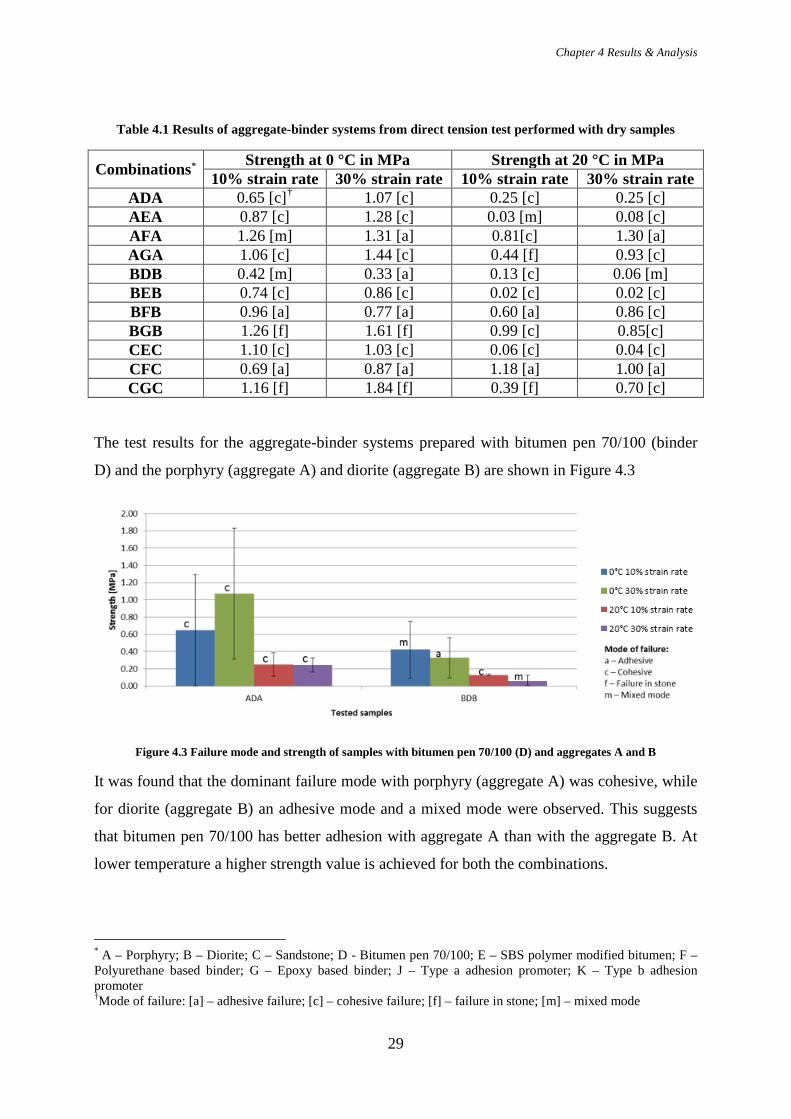
Table 4.1 Results of aggregate-binder systems from direct tension test performed with dry samples
Combinations* Strength at 0 °C in MPa Strength at 20 °C in MPa 10% strain rate 30% strain rate 10% strain rate 30% strain rate
ADA 0.65 [c]† 1.07 [c] 0.25 [c] 0.25 [c] AEA 0.87 [c] 1.28 [c] 0.03 [m] 0.08 [c] AFA 1.26 [m] 1.31 [a] 0.81[c] 1.30 [a] AGA 1.06 [c] 1.44 [c] 0.44 [f] 0.93 [c] BDB 0.42 [m] 0.33 [a] 0.13 [c] 0.06 [m] BEB 0.74 [c] 0.86 [c] 0.02 [c] 0.02 [c] BFB 0.96 [a] 0.77 [a] 0.60 [a] 0.86 [c] BGB 1.26 [f] 1.61 [f] 0.99 [c] 0.85[c] CEC 1.10 [c] 1.03 [c] 0.06 [c] 0.04 [c] CFC 0.69 [a] 0.87 [a] 1.18 [a] 1.00 [a] CGC 1.16 [f] 1.84 [f] 0.39 [f] 0.70 [c]
The test results for the aggregate-binder systems prepared with bitumen pen 70/100 (binder
D) and the porphyry (aggregate A) and diorite (aggregate B) are shown in Figure 4.3
Figure 4.3 Failure mode and strength of samples with bitumen pen 70/100 (D) and aggregates A and B
It was found that the dominant failure mode with porphyry (aggregate A) was cohesive, while
for diorite (aggregate B) an adhesive mode and a mixed mode were observed. This suggests
that bitumen pen 70/100 has better adhesion with aggregate A than with the aggregate B. At
lower temperature a higher strength value is achieved for both the combinations.
* A – Porphyry; B – Diorite; C – Sandstone; D - Bitumen pen 70/100; E – SBS polymer modified bitumen; F – Polyurethane based binder; G – Epoxy based binder; J – Type a adhesion promoter; K – Type b adhesion promoter †Mode of failure: [a] – adhesive failure; [c] – cohesive failure; [f] – failure in stone; [m] – mixed mode

Chapter 4 Results & Analysis
30
Figure 4.4 shows the failure mode and strength for the SBS polymer modified bitumen
(binder E) with all the aggregates.
Figure 4.4 Failure mode and strength of samples with SBS polymer modified bitumen (E) and all aggregate types
It can be noted that SBS polymer modified bitumen (binder E) shows good adhesion
characteristics with all the three aggregates, since the failure mode was cohesive in most
cases. It can also be seen that with binder E, extremely low strength is achieved at high
temperature when compared to that at high temperature. This shows that binder E is highly
temperature sensitive.
Figure 4.5 shows failure mode and strength results for the polyurethane based binder (binder
F) with all the aggregates.
Figure 4.5 Failure mode and strength of samples with polyurethane based binder (F) and all aggregate types
It can be observed that the main failure mode for binder F with all the aggregates was
adhesive, showing that there is an incompatibility of all aggregate types with binder F.
Finally, Figure 4.6 shows the strength and failure mode for the epoxy based binder (binder G)
with all the aggregates.
Chapter 4 Results & Analysis
31
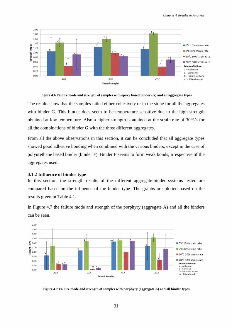
Figure 4.6 Failure mode and strength of samples with epoxy based binder (G) and all aggregate types
The results show that the samples failed either cohesively or in the stone for all the aggregates
with binder G. This binder does seem to be temperature sensitive due to the high strength
obtained at low temperature. Also a higher strength is attained at the strain rate of 30%/s for
all the combinations of binder G with the three different aggregates.
From all the above observations in this section, it can be concluded that all aggregate types
showed good adhesive bonding when combined with the various binders, except in the case of
polyurethane based binder (binder F). Binder F seems to form weak bonds, irrespective of the
aggregates used.
4.1.2 Influence of binder type In this section, the strength results of the different aggregate-binder systems tested are
compared based on the influence of the binder type. The graphs are plotted based on the
results given in Table 4.1.
In Figure 4.7 the failure mode and strength of the porphyry (aggregate A) and all the binders
can be seen.
Figure 4.7 Failure mode and strength of samples with porphyry (aggregate A) and all binder types
Chapter 4 Results & Analysis
32
The results show that the most of the aggregate-binder systems considered above failed
cohesively. An exception was observed in the case of polyurethane based binder (binder F),
where the dominant mode of failure was adhesive. This implies that the cohesive strength of
the binder was lower compared to the strength of the adhesive bond of the binder with the
aggregate. Based on this, it is expected that, the higher the cohesive binder strength, the
higher the bond strength will be. Taking this into account, it can be seen that the epoxy based
binder has a higher adhesive bond strength with the porphyry (aggregate A). While the
bitumen pen 70/100 and the polymer modified bitumen have relatively the same strength
levels. It can be seen clearly that at a higher strain rate of 30%/s, higher strength is achieved
for all combinations. It can also be noted that at lower temperature a higher strength was
obtained for almost all the aggregate-binder systems.
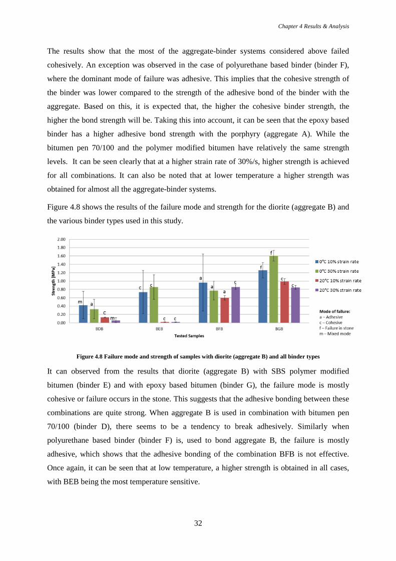
Figure 4.8 shows the results of the failure mode and strength for the diorite (aggregate B) and
the various binder types used in this study.
Figure 4.8 Failure mode and strength of samples with diorite (aggregate B) and all binder types
It can observed from the results that diorite (aggregate B) with SBS polymer modified
bitumen (binder E) and with epoxy based bitumen (binder G), the failure mode is mostly
cohesive or failure occurs in the stone. This suggests that the adhesive bonding between these
combinations are quite strong. When aggregate B is used in combination with bitumen pen
70/100 (binder D), there seems to be a tendency to break adhesively. Similarly when
polyurethane based binder (binder F) is, used to bond aggregate B, the failure is mostly
adhesive, which shows that the adhesive bonding of the combination BFB is not effective.
Once again, it can be seen that at low temperature, a higher strength is obtained in all cases,
with BEB being the most temperature sensitive.

Chapter 4 Results & Analysis
33
Finally, Figure 4.9 depicts the test results from the tension test and the failure mode of the
samples made of sandstone (aggregate C) used in combination with all the four types of
binders.
Figure 4.9 Failure mode and strength of samples with sandstone (aggregate C) and all binder types
The results show that aggregate C in combination with polyurethane based binder (binder F)
fails adhesively under all circumstances implying the formation of weak adhesive bond
between these two materials. However, SBS polymer modified bitumen (binder E) and epoxy
based binder (binder G) seems to forge a strong adhesive bond based on the consistent
cohesive failure mode observed. The combinations CEC and CGC seems to quite temperature
sensitive, based on the vast difference that can be seen in their strength values at high and low
temperature.
Lastly, it can be said that, SBS polymer modified bitumen (binder E) when used with any
aggregate (of the three), the combination becomes highly temperature sensitive. The
polyurethane based binder (binder F) in combination with sandstone (aggregate C) has the
weakest adhesive bond when compared to porphyry (aggregate A) and diorite (aggregate B).
Of the different binders used in this study, epoxy based binder seems to have the strongest
adhesive bonding to all the three types of aggregate (porphyry, diorite and sandstone).
4.1.3 Influence of adhesion promoters The addition of adhesion promoters aims to improve the adhesion of the binder to the
aggregate surface. In this study, the effect of bonding agents was investigated by using two
adhesion promoters, namely, J and K. They were applied to the aggregate-binder
combinations using the polyurethane based binder (binder F) and all the three types of
aggregates. From the previous results it can be seen that the aggregate –binder systems with F
as the binder, showed weak adhesive bonding with all the aggregates. Table 4.2 shows the
strength results of the different combinations that were subject to direct tension test.

Chapter 4 Results & Analysis
34
Table 4.2 Results of aggregate-binder systems from direct tension test performed with dry samples
Combinations‡ Strength at 0 °C [MPa] Strength at 20 °C [MPa] 10% strain rate 30% strain rate 10% strain rate 30% strain rate
AFA 1.26 [m] § 1.31 [a] 0.81 [c] 1.30 [a] AJFJA 1.48 [c] 1.17 [c] 0.40 [c] 0.49 [c]
AKFKA 1.23 [m] 0.85 [c] 1.03 [c] 0.57 [c] BFB 0.96 [a] 0.77 [a] 0.60 [a] 0.86 [c]
BJFJB 1.01 [m] 0.73 [f] 0.24 [c] 0.41 [c] BKFKB 1.00 [f] 1.19 [f] 0.53 [c] 0.82 [m]
CFC 0.69 [a] 0.87 [a] 1.18 [a] 1.00 [a] CJFJC 0.78 [c] 0.84 [c] 0.38 [c] 0.39 [c]
CKFKC 0.95 [c] 0.82 [m] 0.69 [m] 0.68 [c]
Figure 4.10 shows the test results for the porphyry (aggregate A) combined with the
polyurethane based binder (binder F), along with the addition of adhesion promoters (J and K)
to binder F.
Figure 4.10 Failure mode and strength of samples with porphyry (aggregate A) and polyurethane based binder (binder F) along with the adhesion promoters
It can be observed that the use of adhesion promoters (J and K) resulted in a change of mode
from adhesive to cohesive failure. This suggests that the use of adhesion promoters improved
the adhesive characteristics of the aggregate-binder systems. On addition of adhesion
promoter J, it can be seen that the all the failure modes are cohesive, whereas in case of K,
there is still a tendency to break adhesively, at low temperature.
‡ A – Porphyry; B – Diorite; C – Sandstone; D - Bitumen pen 70/100; E – SBS polymer modified bitumen; F – Polyurethane based binder; G – Epoxy based binder; J – Type a adhesion promoter; K – Type b adhesion promoter §Mode of failure: [a] – adhesive failure; [c] – cohesive failure; [f] – failure in stone; [m] – mixed mode

Chapter 4 Results & Analysis
35
Similarly Figure 4.11 and 4.12 shows the test results for the diorite (aggregate B) and
sandstone (aggregate C) combined with the polyurethane based binder (binder F), along with
the addition of adhesion promoters (J and K) to binder F.
Figure 4.11 Failure mode and strength of samples with diorite (aggregate B) and polyurethane based binder (binder F) along with the adhesion promoters
Figure 4.12 Failure mode and strength of samples with sandstone (aggregate C) and polyurethane based binder (binder F) along with the adhesion promoters
It can be seen from the results that the use of adhesion promoters resulted in a change of
failure mode from adhesive to cohesive, for both the aggregate types (B and C). It seems that
adhesion promoter J was more effective in promoting adhesion compared to promoter K,
because at times promoter K changed the mode of failure to a mixed mode and not cohesive.
It can be concluded that use of adhesion promoter indeed helps in improving the adhesive
bonding. However, adhesion promoter J seems more reliable than K given the tendency of the
failure mode to be a mixed mode on addition of promoter K. This might be because that there
is an incompatibility issue between the polyurethane based binder (binder F) and the adhesion

Chapter 4 Results & Analysis
36
promoter K. Thus testing the adhesion promoters, J and K with a different binder might reveal
the nature of the issue observed with the promoter K.
4.2 Results from tests after moisture conditioning Similar to the detailed analysis of results from dry tests performed in the previous section, the
results of the samples tested after the moisture conditioning for 72 hours at 20 °C are
discussed in detail in this section.
4.2.1 Influence of aggregate type In this section, the results are presented in such a way so as to allow for a comparison between
the various aggregate-binder combinations which were moisture conditioned, on the basis of
the aggregates used. Table 4.3 shows the tensile strength of the adhesive bond at 0 °C and 20
°C and at 1%/s and 20%/s strain rate after moisture conditioning.
Table 4.3 Results of aggregate-binder systems from direct tension test performed after moisture conditioning
Combinations** Strength at 0 °C [MPa] Strength at 20 °C [MPa]
10% strain rate 30% strain rate 10% strain rate 30% strain rate
ADA 0.24 [c] †† 0.62 [c] 0.17 [c] 0.20 [c] AEA 0.92 [c] 0.97 [c] 0.04 [c] 0.09 [c] AFA 0.65 [a] 1.57 [a] 1.22 [a] 0.72 [a] AGA 0.96 [m] 0.65 [m] 0.95 [c] 1.02 [c] BDB 0.25 [c] 0.60 [c] 0.20 [c] 0.22 [c] BEB 0.87 [c] 0.99 [c] 0.03 [m] 0.04 [m] BFB 0.40 [m] 0.65 [a] 0.81 [a] 0.75 [a] BGB 0.86 [m] 1.09 [m] 0.88 [m] 0.59 [m] CEC 0.70 [c] 0.83 [c] 0.04 [c] 0.04 [c] CFC 1.18 [a] 1.07 [m] 0.55 [a] 0.73 [a] CGC 0.89 [m] 0.56 [c] 0.93 [f] 1.04 [c]
** A – Porphyry; B – Diorite; C – Sandstone; D - Bitumen pen 70/100; E – SBS polymer modified bitumen; F – Polyurethane based binder; G – Epoxy based binder; J – Type a adhesion promoter; K – Type b adhesion promoter ††Mode of failure: [a] – adhesive failure; [c] – cohesive failure; [f] – failure in stone; [m] – mixed mode
Chapter 4 Results & Analysis
37
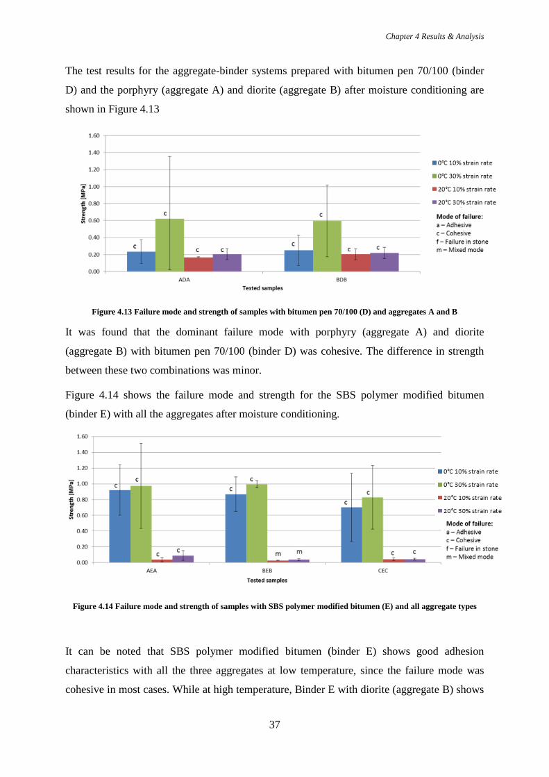
The test results for the aggregate-binder systems prepared with bitumen pen 70/100 (binder
D) and the porphyry (aggregate A) and diorite (aggregate B) after moisture conditioning are
shown in Figure 4.13
Figure 4.13 Failure mode and strength of samples with bitumen pen 70/100 (D) and aggregates A and B
It was found that the dominant failure mode with porphyry (aggregate A) and diorite
(aggregate B) with bitumen pen 70/100 (binder D) was cohesive. The difference in strength
between these two combinations was minor.
Figure 4.14 shows the failure mode and strength for the SBS polymer modified bitumen
(binder E) with all the aggregates after moisture conditioning.
Figure 4.14 Failure mode and strength of samples with SBS polymer modified bitumen (E) and all aggregate types
It can be noted that SBS polymer modified bitumen (binder E) shows good adhesion
characteristics with all the three aggregates at low temperature, since the failure mode was
cohesive in most cases. While at high temperature, Binder E with diorite (aggregate B) shows

Chapter 4 Results & Analysis
38
a mixed mode of failure. It can also be seen that with binder E, extremely low strength is
achieved at high temperature when compared to that at high temperature. This shows that
binder E is highly temperature sensitive.
Figure 4.15 shows failure mode and strength results for the polyurethane based binder (binder
F) with all the aggregates after moisture conditioning.
Figure 4.15 Failure mode and strength of samples with polyurethane based binder (F) and all aggregate types
It can be observed that the main failure mode for binder F with all the aggregates was
adhesive, showing that binder F forms a poor adhesive bond with all the aggregates.
Finally, Figure 4.16 shows strength and failure mode for the epoxy based binder (binder G)
with all the aggregates after moisture conditioning.
Figure 4.16 Failure mode and strength of samples with epoxy based binder (G) and all aggregate types
The results show that the samples failed predominantly in mixed mode. The exception for this
being, the combination of epoxy based binder (binder G) with porphyry (aggregate A) and
sandstone (aggregate C).
Chapter 4 Results & Analysis
39
From all the above observations in this section, it can be concluded that all combinations
showed a tendency to fail adhesively when tested after moisture conditioning. The important
exception to be noted here is the combination of SBS polymer modified bitumen (binder E)
with diorite (aggregate B) at high temperature, it failed in mixed mode, thus showing a
tendency to fail adhesively.
4.2.2 Influence of binder type In this section, the strength results of the different aggregate-binder systems tested are
compared based on the influence of the binder type. The graphs are plotted based on the
results given in Table 4.3.
In Figure 4.17 the failure mode and strength of the porphyry (aggregate A) and all the binders
can be seen.
Figure 4.17 Failure mode and strength of samples with porphyry (aggregate A) and all binder types
The results show that the most of the aggregate-binder systems with binder D and E
considered above failed cohesively. Also the temperature sensitivity of the porphyry
(aggregate A) in combination with binder D and E is more explicit when compared to the
results of samples with binder F and G. With binder F, the dominant mode of failure was
observed to be adhesive. The epoxy based binder (binder G) at low temperature shows a
mixed mode of failure. It can also be seen that at high strain rate and low temperature, a
higher strength is prevalent.
Figure 4.18 shows the results of the failure mode and strength for the diorite (aggregate B)
and the various binder types used in this study after moisture conditioning.

Chapter 4 Results & Analysis
40
Figure 4.18 Failure mode and strength of samples with diorite (aggregate B) and all binder types
It can observed from the results that diorite (aggregate B) with epoxy based bitumen (binder
G), showed a mixed failure mode. This suggests that there is a tendency for the sample to fail
adhesively. Also, the epoxy based binder G does not seem to be very temperature sensitive.
When aggregate B is used in combination with bitumen pen 70/100 (binder D), a cohesive
mode of failure is dominant. The use of polyurethane based binder (binder F) with aggregate
B, results to mostly adhesive failure, which shows that the adhesive bonding of the
combination BFB is not effective. Once again, it can be seen that at low temperature, a higher
strength is obtained in all cases, with BEB being the most temperature sensitive.
Finally, Figure 4.19 depicts the test results from the tension test and the failure mode of the
samples made of sandstone (aggregate C) used in combination with all the four types of
binders.
Figure 4.19 Failure mode and strength of samples with sandstone (aggregate C) and all binder types
The results show that aggregate C in combination with polyurethane based binder (binder F)
fails adhesively most of the time implying the formation of weak adhesive bond between

Chapter 4 Results & Analysis
41
these two materials. However, SBS polymer modified bitumen (binder E) and epoxy based
binder (binder G) seems to forge a strong adhesive bond based on the consistent cohesive
failure mode observed. The combination CEC seems to be quite temperature sensitive, based
on the difference that can be seen in their strength values at high and low temperature. While
CGC seems to be less temperature sensitive.
Lastly, it can be said that, SBS polymer modified bitumen (binder E) when used with any
aggregate (of the three), remains temperature sensitive. The polyurethane based binder (binder
F) in combination with porphyry (aggregate A) has the weakest adhesive bond when
compared to diorite (aggregate B) and sandstone (aggregate C) because the mode of failure in
AFA remains adhesive under all circumstances. Of the different binders used in this study,
epoxy based binder in combination with all the three types of aggregate (porphyry, diorite and
sandstone) is the least temperature susceptible
4.2.3 Influence of adhesion promoters In this section, the effect of bonding agents was investigated by using two adhesion
promoters, namely, J and K. They were applied to the aggregate-binder combinations using
the polyurethane based binder (binder F) and all the three types of aggregates. From the
previous results it can be seen that the aggregate-binder systems with F as the binder, showed
weak adhesive bonding with all the aggregates. Table 4.4 shows the strength results of the
different combinations that were subject to direct tension test after moisture conditioning.
Table 4.4 Results of aggregate-binder systems from direct tension test performed after moisture conditioning
Combinations‡‡ Strength at 0 °C [MPa] Strength at 20 °C [MPa] 10% strain rate 30% strain rate 10% strain rate 30% strain rate
AFA 0.65 [a] §§ 1.57 [a] 1.22 [a] 0.72 [a] AJFJA 0.76 [c] 1.08 [c] 0.66 [c] 0.75 [c]
AKFKA 1.11 [m] 1.17 [a] 0.59 [c] 1.00 [c] BFB 0.40 [m] 0.65 [a] 0.81 [a] 0.75 [a]
BJFJB 0.37 [m] 0.67 [m] 0.82 [c] 0.50 [c] BKFKB 0.60 [f] 1.07 [f] 0.50 [c] 0.65 [c]
CFC 1.18 [a] 1.07 [m] 0.55 [a] 0.73 [a] CJFJC 1.04 [c] 0.92 [m] 0.35 [c] 0.29 [c]
CKFKC 0.70 [c] 0.67 [c] 0.36 [m] 0.64 [c]
‡‡ A – Porphyry; B – Diorite; C – Sandstone; D - Bitumen pen 70/100; E – SBS polymer modified bitumen; F – Polyurethane based binder; G – Epoxy based binder; J – Type a adhesion promoter; K – Type b adhesion promoter §§Mode of failure: [a] – adhesive failure; [c] – cohesive failure; [f] – failure in stone; [m] – mixed mode
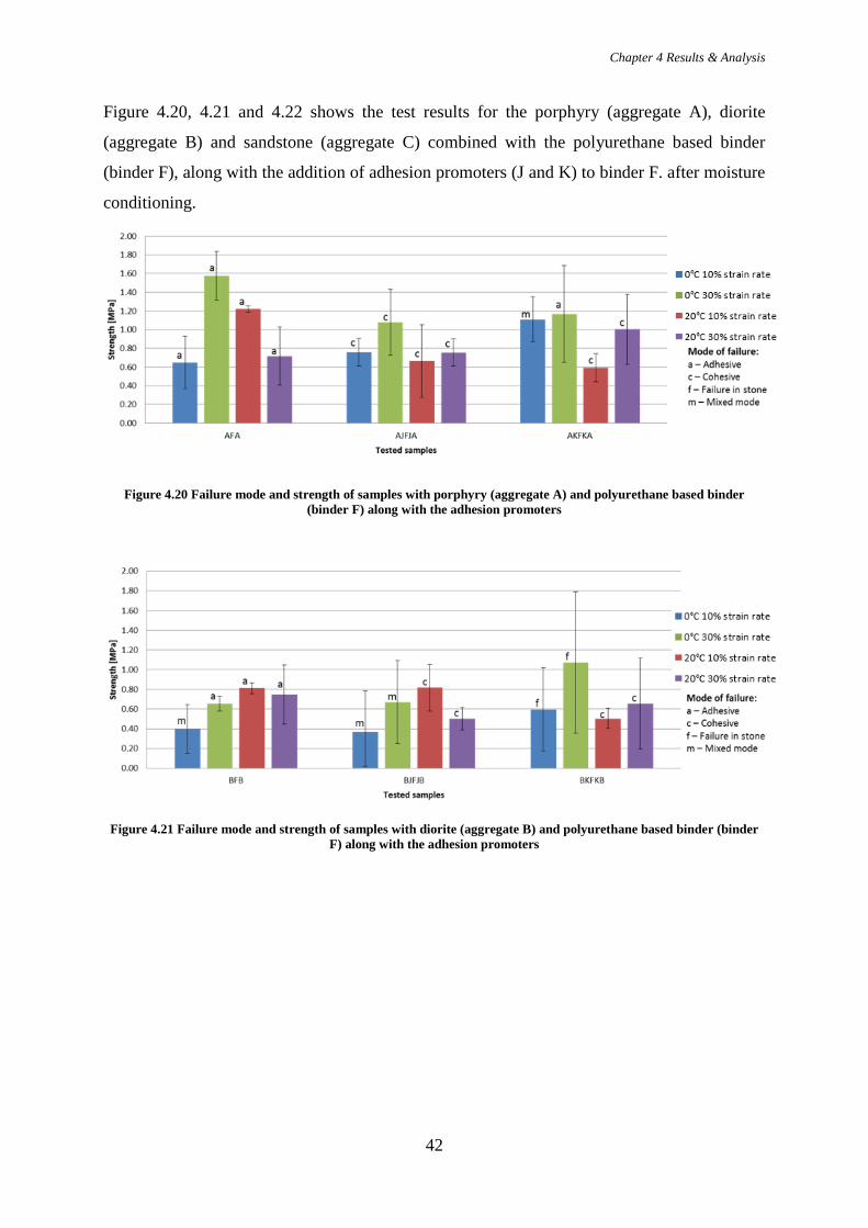
Chapter 4 Results & Analysis
42
Figure 4.20, 4.21 and 4.22 shows the test results for the porphyry (aggregate A), diorite
(aggregate B) and sandstone (aggregate C) combined with the polyurethane based binder
(binder F), along with the addition of adhesion promoters (J and K) to binder F. after moisture
conditioning.
Figure 4.20 Failure mode and strength of samples with porphyry (aggregate A) and polyurethane based binder (binder F) along with the adhesion promoters
Figure 4.21 Failure mode and strength of samples with diorite (aggregate B) and polyurethane based binder (binder F) along with the adhesion promoters
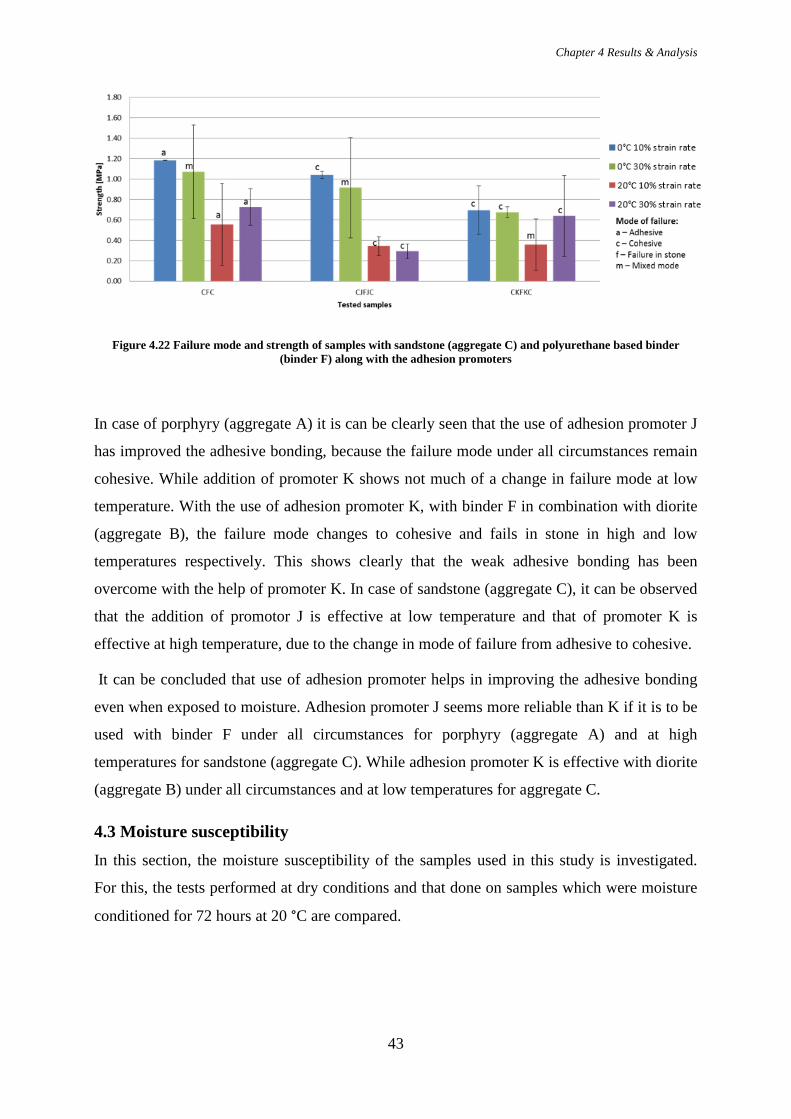
Chapter 4 Results & Analysis
43
Figure 4.22 Failure mode and strength of samples with sandstone (aggregate C) and polyurethane based binder (binder F) along with the adhesion promoters
In case of porphyry (aggregate A) it is can be clearly seen that the use of adhesion promoter J
has improved the adhesive bonding, because the failure mode under all circumstances remain
cohesive. While addition of promoter K shows not much of a change in failure mode at low
temperature. With the use of adhesion promoter K, with binder F in combination with diorite
(aggregate B), the failure mode changes to cohesive and fails in stone in high and low
temperatures respectively. This shows clearly that the weak adhesive bonding has been
overcome with the help of promoter K. In case of sandstone (aggregate C), it can be observed
that the addition of promotor J is effective at low temperature and that of promoter K is
effective at high temperature, due to the change in mode of failure from adhesive to cohesive.
It can be concluded that use of adhesion promoter helps in improving the adhesive bonding
even when exposed to moisture. Adhesion promoter J seems more reliable than K if it is to be
used with binder F under all circumstances for porphyry (aggregate A) and at high
temperatures for sandstone (aggregate C). While adhesion promoter K is effective with diorite
(aggregate B) under all circumstances and at low temperatures for aggregate C.
4.3 Moisture susceptibility In this section, the moisture susceptibility of the samples used in this study is investigated.
For this, the tests performed at dry conditions and that done on samples which were moisture
conditioned for 72 hours at 20 °C are compared.

Chapter 4 Results & Analysis
44
4.3.1 Influence of aggregate type In this section, the results are presented in such a way so as to compare between the various
aggregate-binder combinations on the basis of the aggregates tested at dry condition and after
moisture conditioning.
In Figure 4.23 the test results for the aggregate-binder systems made with bitumen pen 70/100
(binder D) and the porphyry (aggregate A) and diorite (aggregate B) at dry state and after
moisture conditioning are shown.
Figure 4.23 Failure mode and strength of samples with bitumen pen 70/100 (D) and aggregates A and B at (i) dry state and (ii) after moisture conditioning
It can be noted that there was no change in failure mode (cohesive) with porphyry (aggregate
A) with bitumen pen 70/100 (binder D) at both the dry and wet conditions. However, a
decrease in strength is consistent under all circumstances after moisture condition. Another
important observation to be made is that at low temperature, the effect of moisture on this
sample is more, which is evident from the higher difference in the strength degradation. In
case of the sample of diorite (aggregate B) with binder D, on exposure to moisture, change
can be observed in mode of failure. It seems that the adhesive bonding becomes stronger on
exposure to moisture which can be inferred from the change in mode of failure.
Figure 4.24 shows the failure mode and strength for the SBS polymer modified bitumen
(binder E) with all the aggregates at dry conditions and after moisture conditioning.
Figure 4.24 Failure mode and strength of samples with SBS polymer modified bitumen (E) and all aggregate types at (i) dry state and (ii) after moisture conditioning
(i)
(i)
(ii)
Mode of failure: a- Adhesive; c- Cohesive; f- Failure in stone; m- mixed mode
Mode of failure: a- Adhesive; c- Cohesive; f- Failure in stone; m- mixed mode
(ii)

Chapter 4 Results & Analysis
45
It can be seen that the mode of failure has remains almost consistently cohesive, before and
after moisture conditioning. However, the strength of the samples with sandstone (aggregate
C) and binder E has decreased at all testing conditions after exposure to moisture. Even
though it seems to be that the strength of the sample with diorite (aggregate B) and binder E
increases, the error bars indicate that in fact the strength might get lowered. The sample with
porphyry (aggregate A) and binder E, seems not be affected adversely by moisture, because of
the very less difference in the strength that can be seen. The temperature sensitivity of the
binder E has shown no change as well and thus it remains highly temperature sensitive based
on the high difference observed at low and high temperature.
Figure 4.25 shows failure mode and strength results for the polyurethane based binder (binder
F) with all the aggregates at dry condition and after moisture conditioning.
Figure 4.25 Failure mode and strength comparison of samples with polyurethane based binder (F) and all aggregate types at (i) dry state and (ii) after moisture conditioning
It can be observed that the main failure mode for binder F with all the aggregates was
adhesive and continues to be so after moisture conditioning, implying weak adhesive bond
formed on the use of binder F with all the aggregates.
Finally, Figure 4.26 shows comparison of strength and failure mode for the epoxy based
binder (binder G) with all the aggregates at dry and wet conditions
Figure 4.26 Failure mode and strength of samples with epoxy based binder (G) and all aggregate types at (i) dry state and (ii) after moisture conditioning
In case of the samples with the combination of epoxy based binder (binder G) and porphyry
(aggregate A), moisture affects the bonding at low temperature, which can be seen from the
Mode of failure: a- Adhesive; c- Cohesive; f- Failure in stone; m- mixed mode
(i) (ii)
(i) (ii)
Mode of failure: a- Adhesive; c- Cohesive; f- Failure in stone; m- mixed mode
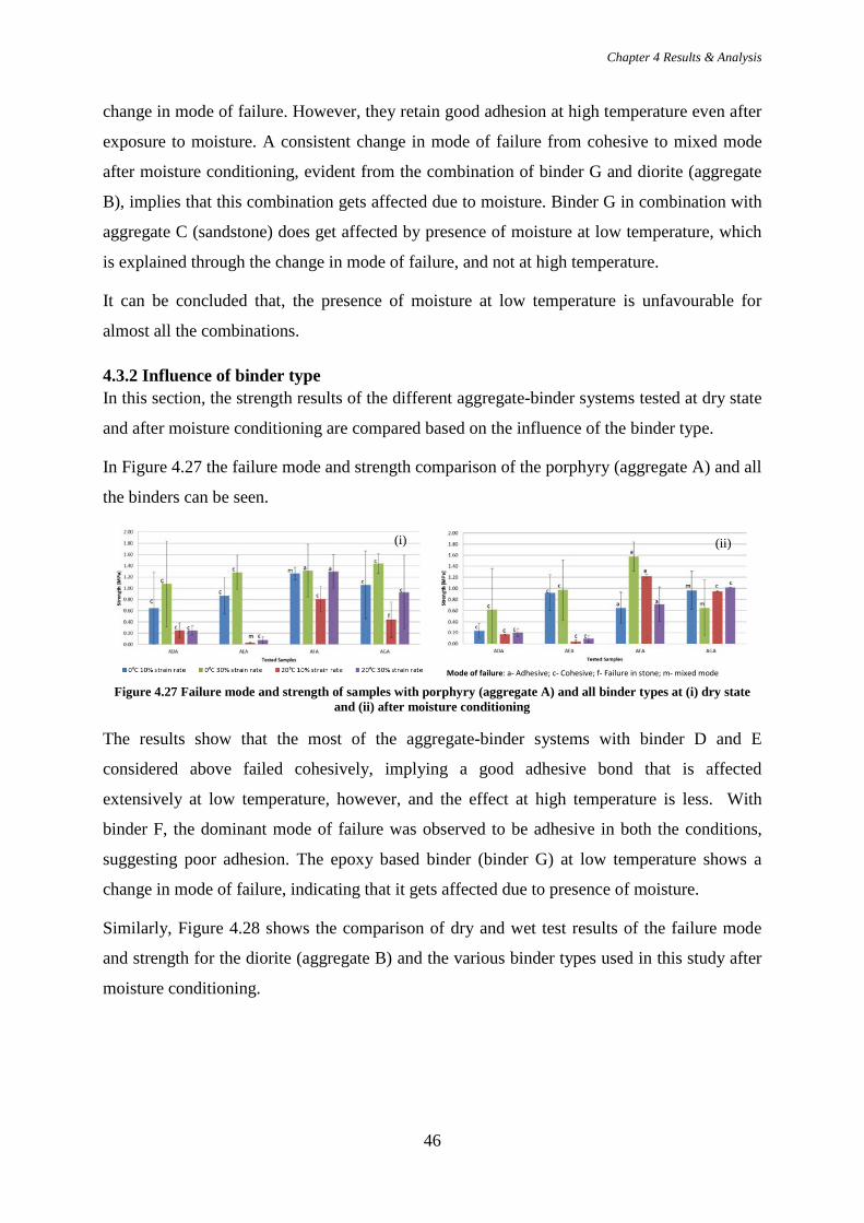
Chapter 4 Results & Analysis
46
change in mode of failure. However, they retain good adhesion at high temperature even after
exposure to moisture. A consistent change in mode of failure from cohesive to mixed mode
after moisture conditioning, evident from the combination of binder G and diorite (aggregate
B), implies that this combination gets affected due to moisture. Binder G in combination with
aggregate C (sandstone) does get affected by presence of moisture at low temperature, which
is explained through the change in mode of failure, and not at high temperature.
It can be concluded that, the presence of moisture at low temperature is unfavourable for
almost all the combinations.
4.3.2 Influence of binder type In this section, the strength results of the different aggregate-binder systems tested at dry state
and after moisture conditioning are compared based on the influence of the binder type.
In Figure 4.27 the failure mode and strength comparison of the porphyry (aggregate A) and all
the binders can be seen.
Figure 4.27 Failure mode and strength of samples with porphyry (aggregate A) and all binder types at (i) dry state and (ii) after moisture conditioning
The results show that the most of the aggregate-binder systems with binder D and E
considered above failed cohesively, implying a good adhesive bond that is affected
extensively at low temperature, however, and the effect at high temperature is less. With
binder F, the dominant mode of failure was observed to be adhesive in both the conditions,
suggesting poor adhesion. The epoxy based binder (binder G) at low temperature shows a
change in mode of failure, indicating that it gets affected due to presence of moisture.
Similarly, Figure 4.28 shows the comparison of dry and wet test results of the failure mode
and strength for the diorite (aggregate B) and the various binder types used in this study after
moisture conditioning.
Mode of failure: a- Adhesive; c- Cohesive; f- Failure in stone; m- mixed mode
(i) (ii)
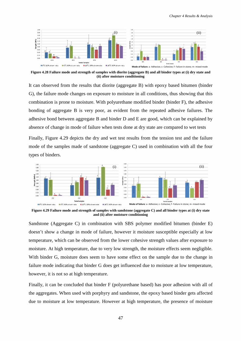
Chapter 4 Results & Analysis
47
Figure 4.28 Failure mode and strength of samples with diorite (aggregate B) and all binder types at (i) dry state and (ii) after moisture conditioning
It can observed from the results that diorite (aggregate B) with epoxy based bitumen (binder
G), the failure mode changes on exposure to moisture in all conditions, thus showing that this
combination is prone to moisture. With polyurethane modified binder (binder F), the adhesive
bonding of aggregate B is very poor, as evident from the repeated adhesive failures. The
adhesive bond between aggregate B and binder D and E are good, which can be explained by
absence of change in mode of failure when tests done at dry state are compared to wet tests
Finally, Figure 4.29 depicts the dry and wet test results from the tension test and the failure
mode of the samples made of sandstone (aggregate C) used in combination with all the four
types of binders.
Figure 4.29 Failure mode and strength of samples with sandstone (aggregate C) and all binder types at (i) dry state and (ii) after moisture conditioning
Sandstone (Aggregate C) in combination with SBS polymer modified bitumen (binder E)
doesn’t show a change in mode of failure, however it moisture susceptible especially at low
temperature, which can be observed from the lower cohesive strength values after exposure to
moisture. At high temperature, due to very low strength, the moisture effects seem negligible.
With binder G, moisture does seem to have some effect on the sample due to the change in
failure mode indicating that binder G does get influenced due to moisture at low temperature,
however, it is not so at high temperature.
Finally, it can be concluded that binder F (polyurethane based) has poor adhesion with all of
the aggregates. When used with porphyry and sandstone, the epoxy based binder gets affected
due to moisture at low temperature. However at high temperature, the presence of moisture
(i)
(i)
(ii)
Mode of failure: a- Adhesive; c- Cohesive; f- Failure in stone; m- mixed mode
(ii)
Mode of failure: a- Adhesive; c- Cohesive; f- Failure in stone; m- mixed mode
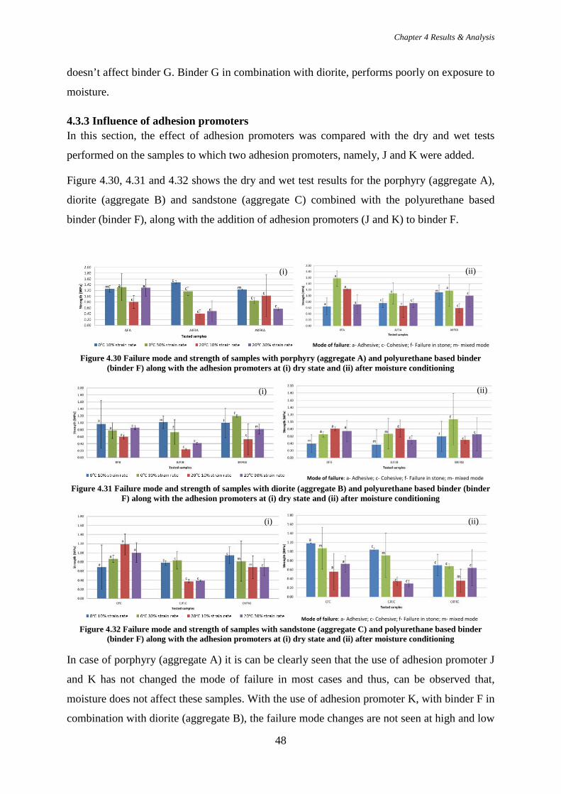
Chapter 4 Results & Analysis
48
doesn’t affect binder G. Binder G in combination with diorite, performs poorly on exposure to
moisture.
4.3.3 Influence of adhesion promoters In this section, the effect of adhesion promoters was compared with the dry and wet tests
performed on the samples to which two adhesion promoters, namely, J and K were added.
Figure 4.30, 4.31 and 4.32 shows the dry and wet test results for the porphyry (aggregate A),
diorite (aggregate B) and sandstone (aggregate C) combined with the polyurethane based
binder (binder F), along with the addition of adhesion promoters (J and K) to binder F.
Figure 4.30 Failure mode and strength of samples with porphyry (aggregate A) and polyurethane based binder (binder F) along with the adhesion promoters at (i) dry state and (ii) after moisture conditioning
Figure 4.31 Failure mode and strength of samples with diorite (aggregate B) and polyurethane based binder (binder F) along with the adhesion promoters at (i) dry state and (ii) after moisture conditioning
Figure 4.32 Failure mode and strength of samples with sandstone (aggregate C) and polyurethane based binder (binder F) along with the adhesion promoters at (i) dry state and (ii) after moisture conditioning
In case of porphyry (aggregate A) it is can be clearly seen that the use of adhesion promoter J
and K has not changed the mode of failure in most cases and thus, can be observed that,
moisture does not affect these samples. With the use of adhesion promoter K, with binder F in
combination with diorite (aggregate B), the failure mode changes are not seen at high and low
Mode of failure: a- Adhesive; c- Cohesive; f- Failure in stone; m- mixed mode
(i) (ii)
(i) (ii)
Mode of failure: a- Adhesive; c- Cohesive; f- Failure in stone; m- mixed mode
Mode of failure: a- Adhesive; c- Cohesive; f- Failure in stone; m- mixed mode
(i) (ii)

Chapter 4 Results & Analysis
49
temperatures respectively. This shows clearly that the weak adhesive bonding has overcome
with the help of promoter K and it is not affected by presence of moisture. However, in case
of the sample where aggregate B is in combination with adhesion promoter J, a change in the
failure mode at low temperature reveals the susceptibility of the promoter to moisture. In case
of sandstone (aggregate C), it was observed that the addition of promoter J is affected by
presence of moisture at low temperature, however promoter K is helps improve the adhesion.
It can be concluded that use of adhesion promoter J seems to be affected by moisture at low
temperature when used with diorite and sandstone and not with porphyry. However adhesion
promoter K gets affected by the presence of moisture only when used in combination with
porphyry.

Chapter 5 Conclusions & Recommendations
50
5. CONCLUSIONS AND RECOMMENDATIONS In this study, the adhesive bond strength of various aggregate-binder combinations was
investigated by means of direct tension tests. Three types of aggregates, namely, porphyry
(aggregate A), diorite (aggregate B) and sandstone (aggregate C) were used in combination
with four types of binders namely, bitumen pen 70/100 (binder D), SBS polymer modified
binder (binder E), polyurethane based binder (binder F) and epoxy based binder (Binder F).
Also, the use of two types of adhesion promoters (J and K) was evaluated with respect to their
ability to enhance adhesion between aggregates and binders. The various aggregate-binder
systems were subject to tensile force at two different strain rates of 10%/s and 30%/s and at
two different temperatures 0oC and 20oC. To investigate the effects of moisture, tests were
performed at dry conditions and after the samples were moisture conditioned for 72 hours at
20oC. These test results were then analysed and the following section presents the conclusions
made from these tests.
5.1 Conclusions From this study, the following conclusions can be made:
Binders
• In general, bitumen pen (70/100) (binder D) has good adhesive bonding to the
aggregates, but it does not belong to the strongest combinations in this test.
• SBS polymer modified binder (binder E) also shows good adhesion to the aggregates,
however, this is true only at low temperature. This binder is highly temperature
susceptible.
• Polyurethane based binder (binder F) has a very poor adhesion to all the types of
aggregates at both high and low temperature. It is extremely moisture susceptible.
Polyurethane based binder (binder F) cannot be used alone without the use of any kind
of adhesion promoter.
• Epoxy based binder (Binder G) forms the strongest adhesive bonding with porphyry
(aggregate C), diorite (aggregate B) and sandstone (aggregate C). However, it was
found that it was very moisture susceptible.
Adhesion promoters
• Both the adhesion promoters, J and K, improve the adhesion of the polyurethane based
binder (binder F) with the aggregates.

Chapter 5 Conclusions & Recommendations
51
• Adhesion promoter J works better with polyurethane based binder (binder F) than
promoter K.
Moisture susceptibility
• The presence of moisture in the samples at low temperatures affects the adhesion
between the aggregate-binder systems. However the effect is not so adverse at high
temperature.
• Polyurethane and epoxy based binder (F and G) are highly moisture susceptible.
• Adhesion promoter J is more moisture susceptible than promoter K at low
temperature.
The direct tension is very effective in showing the trends in which the mode of failure might
occur thus helping in quantifying adhesion. When we are able to link this to the mixture level,
this test will be very useful. The equipment and material requirements for this test are very
basic and thus can be carried out in any tensile testing machine, if the temperature
requirements can be met.
5.2 Recommendations In this section, recommendations are given so that these tests can be put to better use.
• In order to improve the reliability of the test method followed in this study, it is
recommended to use a minimum of five replicate samples for each test.
• Testing the samples at various moisture intervals could provide an indication of the
durability of the binder-aggregate systems over time.
• The adhesion promoters can be tested with other types of binders which may give an
insight into the better performing promoters.
• The use of XRF method did not seem to provide enough insights on the adhesion
characteristics of the aggregates. The use of more dedicated tests, such as X-ray
Diffraction (XRD) tests, is recommended in future studies. Moreover, the chemical
characterization of the various binders could be beneficial in understanding adhesion
of aggregate-binder systems.
• Testing the effects of ageing of the materials on their adhesive characteristics might
give very interesting results, which may even completely change the preferences.
• Testing the samples at temperatures like -5°C or -10°C will help in understanding the
adhesion behaviour of aggregate-binder at freezing conditions.

Chapter 5 Conclusions & Recommendations
52
• It also is recommended to try link the results from the material level, to the mix level.
In doing so, the work of choosing the right materials to be used in a durable pavement
mixture will become more clear.

References
52
REFERENCES
[1] L. F. d. Silva, A. Ochsner and R. D. Adams, Handbook of Adhesion Technology,
Heidelberg: Springer, 2011.
[2] S. Ebnesajjad, Handbook of Adhesives and Surface Preparation: Technology,Application
and Manufactureing, Oxford: Elsevier Inc., 2011.
[3] D. E. Packham, Handbook of Adhesion Second Edition, West Sussex, UK: John Wiley
and Sons Ltd., 2005.
[4] J. J. Bikerman, “Causes of Poor Adhesion: Weak Boundary Layers,” in Industrial
Engineering Chemistry , 1967.
[5] H. Bahia, R. Moraes and R. Velasquez, “The Effect Bitumen Stiffness on the Adhesive
Strength Measured by Bitumen Bond Strength Test,” in Transportation Research Board
Annual Meeting, Washington D.C., 2011.
[6] S. Mondal, A. Das and A. Ghatak, “Effect of Thickness of a Sandwiched Layerof
Bitumen between Two Aggregates on the Bond Strength: An Experimental Study,” in
7th RILEM International Conference on Cracking in Pavements, 2012.
[7] E. Masad, C. Zollinger, B. R., D. Little and R. Lytton, “Characterization of HMA
moisture damage using surface energy and fracture properties,” Journal of the
Association of Asphalt Paving Technologists, vol. 75, pp. 713-754, 2006.
[8] A. Tarrer and V. Wagh, “The Effect of Physical and Chemical Characteristics of thr
Aggregate on Bonding,” Strategic Highway Research Program; National research
Council, Washington D.C., 1991.
[9] S. K. Das, “Evaluation of Asphalt— Aggregate Bond and Stripping Potential,” Tubbock,
Texas, 2004.
[10] D. R. J. Dallas N. Little, “Chemical and Mechanical Processes of Moisture Damage in
Hot-Mix Asphalt Pavements,” in Moisture Sensitivity of Asphalt Pavements - A NAtional
Seminar, San Diego, 2003.
[11] S. Cui, B. R. Blackman, A. J. Kinloch and A. C. Taylorn, “Durability of asphalt

References
53
mixtures: Effect of aggregate type and adhesion promoters,” International Journal of
Adhesion and Adhesives, pp. 100-111, 2014.
[12] C. W. Curtis, “Investigation of Asphalt Aggregate Interactions in Asphalt Pavements,”
1993.
[13] New World Encyclopedia, “Porphyry (Geology),” 26 May 2015. [Online]. [Accessed 15
Decemeber 2015].
[14] Pavement Interactive, “Aggregates,” [Online]. Available:
http://www.pavementinteractive.org/article/aggregate/. [Accessed 22 January 2016].
[15] New World Encyclopedia Contributors, “Sandstone,” 18 August 2015. [Online].
Available:
http://www.newworldencyclopedia.org/p/index.php?title=Sandstone&oldid=990103.
[Accessed 15 Decemeber 2015].
[16] D. J. Read and M. D. Whiteoak, Shell Bitumen Handbook, London: Thomas Telford
Publishing, 2003.
[17] Bitumina , “What is Bitumen (Asphalt)?,” [Online]. Available:
http://www.bitumina.co.uk/whatisbitumen.html. [Accessed 15 December 2015].
[18] J. Zhu, B. Birgisson and N. Kringos, “Polymer modification of bitumen: Advances and
challenges,” European Polymer Journal, pp. 18-38, 2014.
[19] Bitumina , “Polymer Modified Bitumen,” [Online]. Available:
http://www.bitumina.co.uk/polymer-modified-bitumen.html. [Accessed 15 December
2015].
[20] S. Ebnesajjad, Adhesives Technology Handbook, New York: William Andrew Inc.,
2008.
[21] D. Q. v. Lent, “Interfacial interactions and mass transfer at the interfacial region of
bituminous hydrocarbon mixtures,” Diederik van Lent, Delft, 2013.
[22] A. K. Apeagyei, J. R. A. Grenfella and G. D. Airey, “Moisture-induced strength
degradation of aggregate–asphalt mastic bonds,” Road Materials and Pavement Design,
pp. 239-262, 2014.
References
54
[23] R. O. Ebewele, Polymer Science and Technology, Florida: CRC Press, 2000.
[24] D. L. Allara, “Aging of Polymers,” Environmental Health Perspectives Vol. 11, pp. 29-
45, 1975.
[25] R. L. Feller, Accelerated Aging - Photochemical adn Thermal Aspects, The J. Paul Getty
Trust, 1994.
[26] R. Garba, “Permanent Deformation Properties of Asphalt Concrete Mixtures,”
Department of Road end Railway Engineering Norwegian University of Science and
Technology nce and Technology NTNU, Trondheim, Norway, 2002.
[27] A. Bhasin and D. N. Little, “Application of Microcalorimeter to Characterize Adhesion
between Asphalt Binders and Aggregates,” Journal of Materials in Civil Engineering,
pp. 235-243, 2009.
[28] M. B. Evans, D. V. Nowell and M. W. Powell, “Determination of Adhesion in Bitumen
Systems by Heat of Immersion Calorimetry II. Correlation of chemical properties with
adhesion,” Journal of Thermal Analysis, Vol. 40, pp. 121-131, 1993.
[29] H. Tang, B. Foran and D. C. Martin, “Quantitative Measurement of Adhesion between
Polypropylene Blends and paints by Tensile Mechanical Testing.,” 2001.
[30] L. M. M. Huurman, “Fatigue in mortar and adhesive zones; measurements, test
interpretation and determinaion of model paramters,” Delft , 2007.
[31] D. Q. V. Lent, “Interfacial Interactions and mass transfer at the interfacial region of
bituminous hydrocarbon mixtures,” Delft, 2013.
[32] H. J. Fromm, “The Mechanisms of Asphalt Stripping from aggregate surfaces,” in AAPT,
Vol 43, , Wiiliamsburg, 1974.
[33] H. D. Silva, J. C. Pais, P. Pereira and L. Picado-Santos, “Evaluation of the bond between
mastic and coarse aggregate,” 2003.
[34] D. L. AIlara, “Aging of Polymers,” Environmental Health Perspectives, vol. 11, pp. 29-
33, 1975.
[35] E. V. Dave, W. G. Buttlar and G. H. Paulino, “Asphalt Pavement Aging and Temperature
Dependent Properties through a Functionally Graded Viscoelastic Model, Part-II:
References
55
Applications,” Materials Science Forum , Vols. 631-632, pp. 53-58, 2010.
[36] University of Virginia, “Chapter 16. Polymers. Characteristics, Applications and
Processing,” University of Virginia, [Online]. Available:
http://www.virginia.edu/bohr/mse209/chapter16.htm. [Accessed April 2015].
[37] K. Kubo, “Present Status of Porous Elastic Rubber Surface PERS) in Japan,” in
inter.noise, Osaka, 2011.
[38] D. M. Brewis and I. Mathieson, “Adhesion and bonding to polyolefins,” RAPRA
Technology Ltd, 2001.
[39] C. Mattson, “The Physics of Adhesives,” 2014. [Online]. Available: http://ffden-
2.phys.uaf.edu/webproj/212_spring_2014/Connor_Mattson/connor_mattson/index.html.
[Accessed 22 January 2016].
[40] Reserach Gate, “Figure 14 Revised scheme for weak boundary layer in wood adhesion
[151],” [Online]. Available:
https://www.researchgate.net/figure/271027812_fig14_Figure-14-Revised-scheme-for-
weak-boundary-layer-in-wood-adhesion-151. [Accessed 22 January 2016].
[41] A. Alden, “Igneous Rock Types; Porphyry,” 2007. [Online]. Available:
http://geology.about.com/od/rocks/ig/igrockindex/pocpicporphyry.htm#step-heading.
[Accessed 15 December 2015].
[42] T. E. o. E. Britannica, “Sandtone,” 2015. [Online]. Available:
http://www.britannica.com/science/sandstone. [Accessed 15 December 2015].
[43] A. Alden, “About Sandstone,” [Online]. Available:
http://geology.about.com/cs/basics_roxmin/a/aa011804c.htm. [Accessed 15 December
2015].
[44] Bruker, “X-ray Fluorescence (XRF),” [Online]. Available:
https://www.bruker.com/products/x-ray-diffraction-and-elemental-analysis/handheld-
xrf/how-xrf-works.html. [Accessed 22 January 2016].
[45] D. J. Read and M. D. Whiteoak, Shell Bitumen Handbook, London: Thomas Telford
Publishing, 2003.
References
56
[46] J. Zhu, B. Birgisson and N. Kringos, “Polymer modification of bitumen: Advances and
challenges,” European Polymer Journal, pp. 18-38, 2014.
[47] F. M. Jakarni, “Adhesion of Asphalt Mixtures,” University of Nottingham, Nottingham,
2012.