ADEPT SR-1 Development and Testing - colorado.edu · ADEPT SR-1 Flight Test: September 12th, 2018...
12
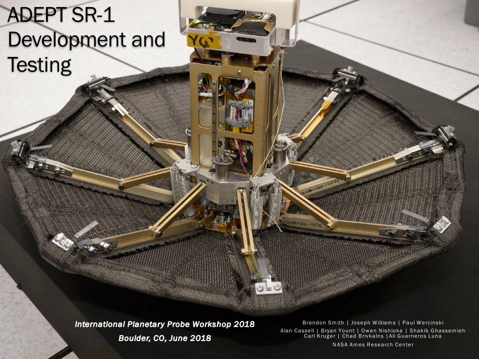
ADEPT SR-1 Development and Testing Brandon Smith | Joseph Williams | Paul Wercinski Alan Cassell | Bryan Yount | Owen Nishioka | Shakib Ghassemieh Carl Kruger | Chad Brivkalns |Ali Guarneros Luna NASA Ames Research Center International Planetary Probe Workshop 2018 Boulder, CO, June 2018
Transcript of ADEPT SR-1 Development and Testing - colorado.edu · ADEPT SR-1 Flight Test: September 12th, 2018...
ADEPT SR-1Development and Testing
Brandon Sm ith | Joseph W illiam s | Paul W ercinskiA lan Cassell | Bryan Yount | Ow en N ishioka | Shakib G hassem ieh
Carl K ruger | Chad Brivkalns |Ali G uarneros LunaN ASA Am es Research Center
International Planetary Probe Workshop 2018
Boulder, CO, June 2018
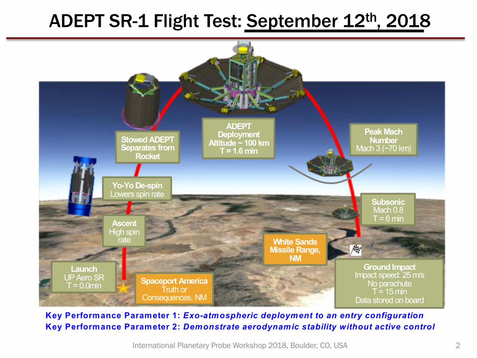
ADEPT SR-1 Flight Test: September 12th, 2018
2International Planetary Probe Workshop 2018, Boulder, CO, USA
LaunchUP Aero SRT = 0.0min Spaceport America
Truth or Consequences, NM
AscentHigh spin
rate
Yo-Yo De-spinLowers spin rate
Stowed ADEPT Separates from
Rocket
ADEPT Deployment
Altitude ~ 100 kmT = 1.6 min
Peak Mach Number
Mach 3 (~70 km)
Ground ImpactImpact speed: 25 m/s
No parachuteT = 15 min
Data stored on board
SubsonicMach 0.8T = 6 min
White Sands Missile Range,
NM
Key Performance Parameter 1: Exo-atmospheric deployment to an entry configurationKey Performance Parameter 2: Demonstrate aerodynamic stability without active control
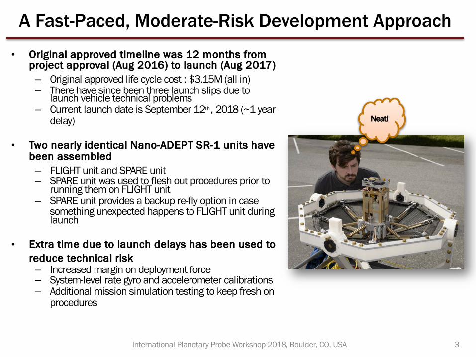
A Fast-Paced, Moderate-Risk Development Approach
• Original approved timeline was 12 months from project approval (Aug 2016) to launch (Aug 2017)– Original approved life cycle cost : $3.15M (all in)– There have since been three launch slips due to
launch vehicle technical problems– Current launch date is September 12th, 2018 (~1 year
delay)
• Two nearly identical Nano-ADEPT SR-1 units have been assembled– FLIGHT unit and SPARE unit– SPARE unit was used to flesh out procedures prior to
running them on FLIGHT unit – SPARE unit provides a backup re-fly option in case
something unexpected happens to FLIGHT unit during launch
• Extra time due to launch delays has been used to reduce technical risk– Increased margin on deployment force– System-level rate gyro and accelerometer calibrations– Additional mission simulation testing to keep fresh on
procedures
3International Planetary Probe Workshop 2018, Boulder, CO, USA
Neat!
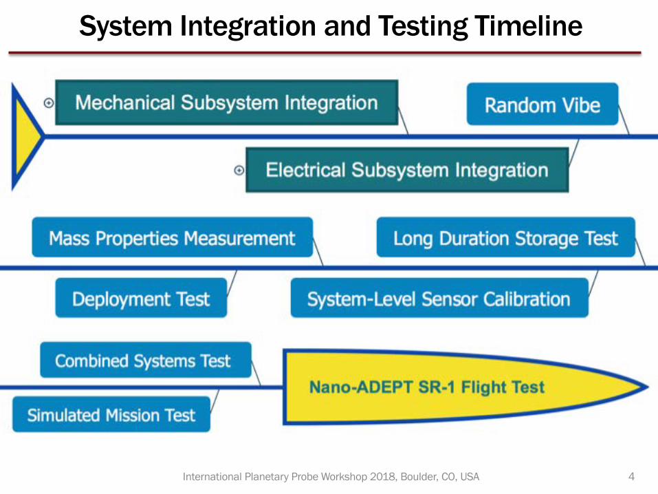
System Integration and Testing Timeline
4International Planetary Probe Workshop 2018, Boulder, CO, USA
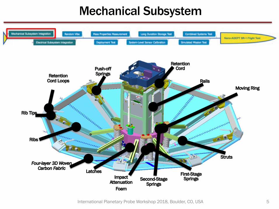
Mechanical Subsystem
5International Planetary Probe Workshop 2018, Boulder, CO, USA
Four-layer 3D Woven Carbon Fabric
Rib Tips
Retention Cord Loops
Push-off Springs
Retention Cord
Ribs
Struts
First-Stage SpringsSecond-Stage
Springs
Latches
Rails
Impact Attenuation
Foam
Moving Ring
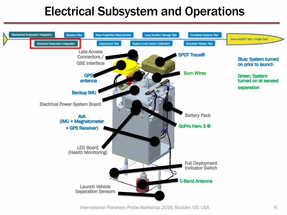
Electrical Subsystem and Operations
6International Planetary Probe Workshop 2018, Boulder, CO, USA
GPS antenna
SPOT Trace®Late Access Connectors / GSE Interface
Burn Wires
Electrical Power System Board
GoPro Hero 3 ®
LED Board (Health Monitoring)
Full Deployment Indicator Switch
C-Band AntennaLaunch Vehicle
Separation Sensors
AVA (IMU + Magnetometer
+ GPS Receiver)
Battery Pack
Backup IMU
Blue: System turned on prior to launch
Green: System turned on at sensed separation
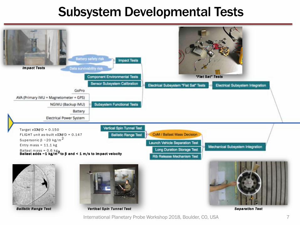
Subsystem Developmental Tests
7International Planetary Probe Workshop 2018, Boulder, CO, USA
Ballistic R ange Test Vertica l Sp in Tunnel Test Separation Test
“F lat Sat” Tests
Im pact Tests
Target xCOM/D = 0 .150FLIG HT unit as-built xCOM/D = 0 .147Supersonic b ~20 kg/m 2
Entry m ass = 11 .1 kgBallast m ass = 0 .6 kg Ballast adds ~1 kg/m 2 to b and < 1 m /s to im pact ve locity
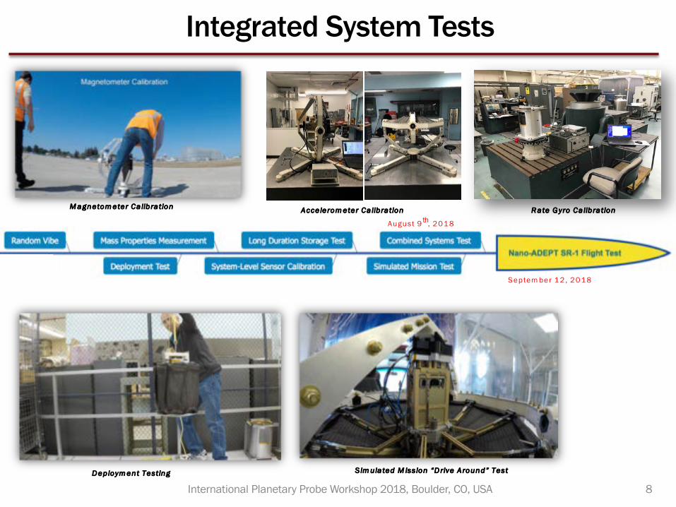
Integrated System Tests
8International Planetary Probe Workshop 2018, Boulder, CO, USAD eploym ent Testing S im ulated M ission “D rive Around” Test
M agnetom eter Ca libration Acce lerom eter Ca libration R ate G yro Ca libration
Septem ber 12 , 2018
August 9 th, 2018
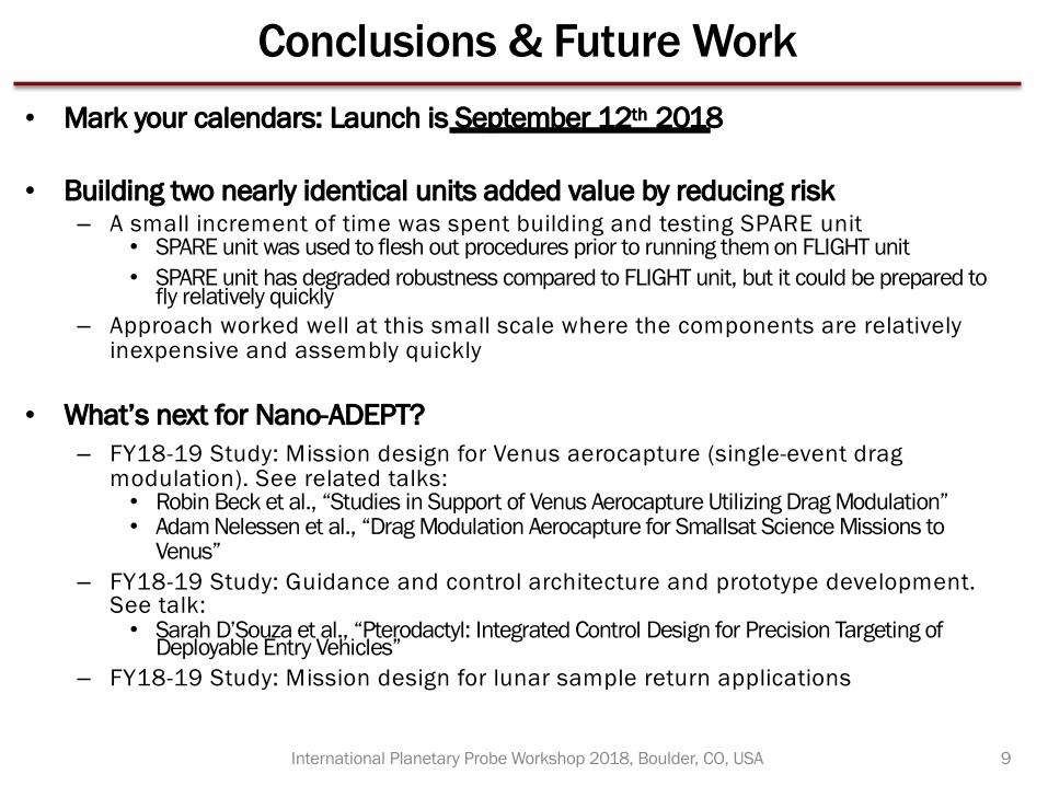
Conclusions & Future Work• Mark your calendars: Launch is September 12th 2018
• Building two nearly identical units added value by reducing risk– A small increment of time was spent building and testing SPARE unit
• SPARE unit was used to flesh out procedures prior to running them on FLIGHT unit • SPARE unit has degraded robustness compared to FLIGHT unit, but it could be prepared to
fly relatively quickly– Approach worked well at this small scale where the components are relatively
inexpensive and assembly quickly
• What’s next for Nano-ADEPT?– FY18-19 Study: Mission design for Venus aerocapture (single-event drag
modulation). See related talks:• Robin Beck et al., “Studies in Support of Venus Aerocapture Utilizing Drag Modulation”• Adam Nelessen et al., “Drag Modulation Aerocapture for Smallsat Science Missions to
Venus”– FY18-19 Study: Guidance and control architecture and prototype development.
See talk:• Sarah D’Souza et al., “Pterodactyl: Integrated Control Design for Precision Targeting of
Deployable Entry Vehicles”– FY18-19 Study: Mission design for lunar sample return applications
9International Planetary Probe Workshop 2018, Boulder, CO, USA
Backup
10International Planetary Probe Workshop 2018, Boulder, CO, USA
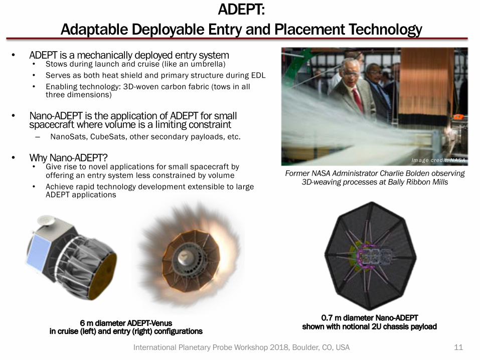
ADEPT: Adaptable Deployable Entry and Placement Technology
• ADEPT is a mechanically deployed entry system• Stows during launch and cruise (like an umbrella)• Serves as both heat shield and primary structure during EDL• Enabling technology: 3D-woven carbon fabric (tows in all
three dimensions)
• Nano-ADEPT is the application of ADEPT for small spacecraft where volume is a limiting constraint– NanoSats, CubeSats, other secondary payloads, etc.
• Why Nano-ADEPT?• Give rise to novel applications for small spacecraft by
offering an entry system less constrained by volume• Achieve rapid technology development extensible to large
ADEPT applications
6 m diameter ADEPT-Venus in cruise (left) and entry (right) configurations
0.7 m diameter Nano-ADEPT shown with notional 2U chassis payload
11
Former NASA Administrator Charlie Bolden observing 3D-weaving processes at Bally Ribbon Mills
Im age credit: NASA
International Planetary Probe Workshop 2018, Boulder, CO, USA
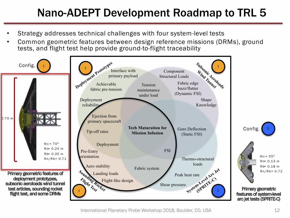
Nano-ADEPT Development Roadmap to TRL 5
Deployment Prototypes Subsonic Aeroloads
Wind Tunnel
Sounding Rocket
Flight Test System-Level A
rc Jet
(SPRITE-C)
Ejection from primary spacecraft
Deployment
Pre-Entry orientation
Peak heat rate
Thermo-structural loads
FSI
Landing loads
Aero stability
Shear pressure
Component Structural Loads
Shape Knowledge
Gore Deflection (Static FSI)
Fabric edge buzz/flutter
(Dynamic FSI)
Flight-like design
Deployment reliability
Interface with primary payload
Achievable fabric pre-tension
Tip-off rates Tech Maturation for
Mission Infusion
Tension maintenance under load
Fabric system
Primary geometric features of system-level arc jet tests (SPRITE-C)
Q c = 55ºRn= 0 .13 mRb= 0 .18 mRn/Rb= 0 .72Primary geometric features of
deployment prototypes, subsonic aeroloads wind tunnel
test articles, sounding rocket flight test, and some DRMs
0.70 m
Q c = 70ºRn= 0 .25 mRb= 0 .35 mRn/Rb= 0 .71
12
• Strategy addresses technical challenges with four system-level tests• Common geometric features between design reference missions (DRMs), ground
tests, and flight test help provide ground-to-flight traceability
1
2
2
1 1
1
Config.
Config.
International Planetary Probe Workshop 2018, Boulder, CO, USA