ADDENDUM NO. 3 TELECOMMUNICATION SYSTEMS …
33
ADDENDUM NO. 3 TELECOMMUNICATION SYSTEMS RELOCATION AT THE DELAWARE ARMY NATIONAL GUARD RIVER ROAD TRAINING FACILITY 1197 RIVER ROAD, NEW CASTLE DE 19720 DEARNG CONTRACT NO. 05-2014 FE&ES Comm.: 14-1129A Date of Issue: September 12, 2014 1.0 This Addendum, Addendum No. 3, shall be made part of the Project Manual and Drawings dated August 8, 2014 for the Telecommunication Systems Relocation at the Delaware Army National Guard River Road Training Facility. 2.0 Any provision in any of the Contract Documents which may be in conflict or be inconsistent with the contents of this Addendum shall be void to the extent of such conflicts or inconsistency. 3.0 Bid Date has not changed. Sealed bids for DEARNG Contract No. 05-2014 – Telecommunication Systems Relocation At The Delaware Army National Guard River Road Training Facility 1197 River Road, New Castle De 19720 will be received by the Delaware Army National Guard at the Security Officers desk in the Main Lobby of the Armed Forces Reserve Center located at 250 Airport Road, New Castle, Delaware, 19720-1502, until 1:00 PM local time on Thursday, September 18, 2014, at which time they will be publicly opened and read aloud in the Multipurpose Room located next to the main lobby. Valid driver’s license will be required for site access, front desk where all visitors are required to sign in at the Security Desk. Bidder bears the risk of late delivery. Any bids received after the stated time will be returned unopened. Contractors are reminded to provide ample time to gain access to this secure site. 4.0 Changes to prior Addenda 4.1. There are no Changes to prior Addenda. 5.0 Changes to Specifications 5.1 Appendix E: Add new Appendix E containing the Geotechnical Report. A geotechnical report has been prepared for this Project and is available for information only. The opinions expressed in this report are those of the geotechnical engineer and represent interpretations of subsoil conditions, tests, and results of analyses conducted by the geotechnical engineer. Owner will not be responsible for interpretations or conclusions drawn from this data. Contractor shall make additional test borings and conduct other exploratory operations necessary for dewatering. In the event of a conflict between the recommendations identified in the report and the project specifications, not clarified by Addendum, refer to Specification Section 00 73 13 Article 1.2.4. 6.0 Changes to Drawings: 6.1 There are no Changes to Drawings.
Transcript of ADDENDUM NO. 3 TELECOMMUNICATION SYSTEMS …

ADDENDUM NO. 3
TELECOMMUNICATION SYSTEMS RELOCATION AT THE
DELAWARE ARMY NATIONAL GUARD RIVER ROAD TRAINING FACILITY1197 RIVER ROAD, NEW CASTLE DE 19720
DEARNG CONTRACT NO. 05-2014 FE&ES Comm.: 14-1129A
Date of Issue: September 12, 2014
1.0 This Addendum, Addendum No. 3, shall be made part of the Project Manual and Drawings dated August 8, 2014 for the Telecommunication Systems Relocation at the Delaware Army National Guard River Road Training Facility.
2.0 Any provision in any of the Contract Documents which may be in conflict or be inconsistent with the contents of this Addendum shall be void to the extent of such conflicts or inconsistency.
3.0 Bid Date has not changed. Sealed bids for DEARNG Contract No. 05-2014 – Telecommunication Systems Relocation At The Delaware Army National Guard River Road Training Facility 1197 River Road, New Castle De 19720 will be received by the Delaware Army National Guard at the Security Officers desk in the Main Lobby of the Armed Forces Reserve Center located at 250 Airport Road, New Castle, Delaware, 19720-1502, until 1:00 PM local time on Thursday, September 18, 2014, at which time they will be publicly opened and read aloud in the Multipurpose Room located next to the main lobby. Valid driver’s license will be required for site access, front desk where all visitors are required to sign in at the Security Desk. Bidder bears the risk of late delivery. Any bids received after the stated time will be returned unopened. Contractors are reminded to provide ample time to gain access to this secure site.
4.0 Changes to prior Addenda 4.1. There are no Changes to prior Addenda.
5.0 Changes to Specifications 5.1 Appendix E: Add new Appendix E containing the Geotechnical Report.
A geotechnical report has been prepared for this Project and is available for information only. The opinions expressed in this report are those of the geotechnical engineer and represent interpretations of subsoil conditions, tests, and results of analyses conducted by the geotechnical engineer. Owner will not be responsible for interpretations or conclusions drawn from this data. Contractor shall make additional test borings and conduct other exploratory operations necessary for dewatering. In the event of a conflict between the recommendations identified in the report and the project specifications, not clarified by Addendum, refer to Specification Section 00 73 13 Article 1.2.4.
6.0 Changes to Drawings:
6.1 There are no Changes to Drawings.

Addendum No. 3 Telecommunication Systems Relocation At The Delaware Army National Guard River Road Training Facility Page 2 of 33 7.0 Questions/Clarifications
Q1: There is no work designated for Bldg.# 24A on the matrix on sheet E-6. Are we to assume that there is sufficient rack and housing space for the terminations of the copper, coax and fiber? Will the terminations be done as part of a cutover by others or shall we provide time and material for the terminations?
A1: Provide new rack and housing space for new equipment being terminated in this
Building. All terminations will be completed as part of this contract. Q2: Could you please clarify the work to be completed in Bldg. # 24a. Are there any racks,
fiber panels or copper termination protection to be installed or will new cables be terminated on existing facilities? There is no work shown on the matrix found on page E-6.
A2: Refer to Q1 above. Q3: I cannot find anything in the DTI document (Addendum A) that deals with coax 625 hard
line cable or it’s termination. A3: Refer to Addendum #2, A1. Coaxial 625 services are required by UFC-3-580-01 and can
be found on PDF Page 20 of Appendix B. All terminations must be compatible with this cable.
Q4: Per the chart on drawing E-6 the multimode fiber for the 12 strand is listed as 50/125
but there is no listing for the 72 multimode fiber. Due to the distance called out approx. 3300 feet could you please clarify what type of multi-mode is required on the run? The last page of section 27-53 33 Appendix A list the 72 strand multi-mode to be 50um 10gig@550 meters which is correct?
A4: The 12 strand and 72 strand multimode is to be of the same material, 50/125 micron to
comply with UFC-3-580-01. Q5: Will there be a location onsite for the disposal of excess soil? A5: Refer to Addendum #1. Q6: Would there be flexibility in the pipe alignment? Specifically the run from CMH 6 to
CMH 9 and CMH 9 to CMH 9A would be difficult to have concrete delivered with the pipe alignment per the plans?
A6: Conduit routing shall be as shown on the drawings.

Addendum No. 3 Telecommunication Systems Relocation At The Delaware Army National Guard River Road Training Facility Page 3 of 33
Q7: Addendum 1 states that upon completion a two year warranty is required on work and materials beginning on the date of substantial completion. For the State of Delaware Certified cabling Contractors that must be used for the fiber and cabling portions of this contract will the 25 year performance and 15 year manufacturer’s parts and labor warranty apply as it does under the State of Delaware Contract NO GSS13441-DATA-Cabling?
A7: The required warranty to be provided by the telecommunication contractor under
Contract GSS13441-DATA-Cabling will be strictly enforced. The 2 year warranty is for all work under the project. The 25/15 year warranties will commence concurrently on the date of Substantial Completion.
END OF ADDENDUM #3
Note: No further addenda will be issued unless the bid date is extended.
EF/ef 14-1129A Add No 3
cc: All Registered Plan Holders P File

Duffield Associates, Inc.5400 Limestone Road
Wilmington, DE 19808Phone: 302.239.6634
Fax: 302.239.8485duffnet.com
Enhancing our community one project at a time.
September 11, 2014
CPT. Eugene Bledsoe AFRCDEARNG/FMO 250 Airport Road New Castle, DE 19720
RE: Project No. 2487.GW Subsurface Evaluation
Telecommunication Systems RelocationRiver Road Training Facility New Castle, Delaware
Dear CPT. Bledsoe:
Duffield Associates, Inc. (Duffield Associates) has completed our subsurface evaluation for the proposed underground communication duct banks at the Delaware Army National Guard (DEARNG) River Road Training Facility (RRTF) in New Castle, Delaware. The following report summarizes the data obtained by our field program in the vicinity of the proposed communication duct banks. These services were provided in general accordance with our agreement dated June 10, 2014, revised August 28, 2014.
To assist with the preparation of this proposal, Duffield Associates was provided with a set of drawings titled “State of Delaware, Delaware Army National Guard, Telecommunication Systems Relocation at the River Road Training Facility, 1197 River Road, New Castle, Delaware 19720, DEARNG Project No.: 05-2014,” prepared by Davis, Bowen & Friedel, Inc., dated August 8, 2014. Based on the information provided and our understanding of the project, the project includes the construction of approximately 5,500 linear feet of duct bank for communication lines prior to the proposed construction of two structures. Based on recent discussions with Fayda Engineering & Engineering Solutions, LLC, we understand that several of the below-grade duct bank and manhole structures are proposed to be installed to depths of up to 12 feet below the existing ground surface. The site of the proposed development is at the RRTF, located on Route 9 in New Castle, Delaware.
I. PREVIOUS SUBSURFACE EVALUATION
Duffield Associates previously performed a Geotechnical Evaluation for the 1049th Parking Lot located to the south of the Recruiting Building, as summarized in our report titled “Geotechnical Evaluation, 1049th Parking Lot, River Road Facility,” dated June 11, 2012. A total of six test pits(TP-1 to TP-6) were performed, extending to depths of up to 10 feet below the ground surface. The previous test pit locations are indicated on the location sketch enclosed with this report. Test pit logs from the previous evaluation are also included.
Appendix "E"
Addendum No. 3 Telecommunication Systems Relocation
At The Delaware Army National Guard River Road Training Facility Page 4 of 33

II. FIELD TESTING PROGRAM
Ten test borings (TB-1 to TB-10) were performed in the general vicinity of the proposed communications duct banks at locations marked in the field by Duffield Associates’ representative, as shown on the provided test boring location sketch. Duffield Associates contacted Miss Utility for delineation of utilities in the public “right-of-way” prior to drilling.
The following table summarizes the test borings performed.
Test Boring No.
Approximate Depth of Test Boring (feet)
Approximate Groundwater Depth
During Drilling (feet)[1]
Approximate Groundwater Depth
at Completion (feet)[2]
TB-1 10 Not Observed Caved and Dry TB-2 30 Not Observed Caved and Dry TB-3 10 4.4 5.7TB-4 10 Not Observed Caved and Dry TB-5 25 Not Observed Caved and Dry[3]
TB-6 10 8.8 Caved and Dry TB-7 10 Not Observed Caved and Dry TB-8 25 Not Observed Caved and Dry[3]
TB-9 10 Not Observed Caved and Dry TB-10 30 17.8 17.2
Notes: 1. Groundwater levels during drilling were measured through the augers.
2. Groundwater levels at completion were measured after removal of the augers.
3. Boreholes for TB-5 and TB-8 were left open for approximately 20 hours, and no groundwater was observed prior to backfilling.
The test borings were performed by CGC Geoservices, LLC, an affiliate company of Duffield Associates, utilizing a truck-mounted drill rig. Duffield Associates’ representative reviewed the samples obtained by the drillers. Conditions encountered during the performance of the test borings are summarized on the enclosed test boring logs. At completion of the excavations, the test borings were backfilled with the auger cuttings. Further restoration of the test boring locations was beyond the scope of work performed for this evaluation. However, additional settlement of the materials backfilled in the test borings may occur, resulting in a depression or hole in the ground surface. Consequently, future maintenance and restoration of the site may be required.
Appendix "E"
Addendum No. 3 Telecommunication Systems Relocation
At The Delaware Army National Guard River Road Training Facility Page 5 of 33

III. SUBSURFACE CONDITIONS
Beneath a surficial layer of topsoil and fill, the underlying stratum observed in the test borings generally consisted of soft to stiff consistency silt with varying amounts of sand and organics. This layer was generally observed to depths of 3 to 10 feet below the existing ground surface (b.e.g.s.). Below the silt layer, varicolored stiff clay was observed to the extent of the borings with the exception of TB-1 to TB-3, TB-5, and TB-8. In test borings TB-1 to TB-3, an approximately 2 to 5-foot-thick medium density sand layer was observed between the silt and clay layers. In test borings TB-5 and TB-8, medium density sand with varying amounts of silt was observed beneath the silt layer and extended to the extent of the borings.
Groundwater was observed in the test borings at depths ranging from 4.4 to 17.8 feet b.e.g.s. in test borings TB-3, TB-6, and TB-10, and was not observed in the remaining test borings. The boreholes for test borings TB-5 and TB-8 were each extended to depths of up to 25 feet below the ground surface and allowed to remain open for approximately 20 hours. Groundwater was not observed in the boreholes after approximately 20 hours.
Groundwater levels at the site will be affected by seasonal and annual variations in precipitation. It is estimated that variations in groundwater levels several feet higher or lower than those observed during this evaluation could be experienced during extreme variations in precipitation. Groundwater mapping by DGS and the current State of Delaware, Department of National Resources and Environmental Control (DNREC) well permit database indicates average groundwater levels in “normal” or “dry” conditions may be in the range of approximately 3 to 20 feet b.e.g.s., and in the range of 3 to 16 feet b.e.g.s. in “wet” conditions. The reported depth to groundwater decreases closer to the Delaware River. Where groundwater was encountered in the test borings, the conditions observed generally appeared consistent with the available data under “dry” conditions. However, the conditions were variable and groundwater was not observed in seven of the ten test borings. Due to the presence of silt lenses and shallow silt soils, it is likely that localized perched on confined groundwater conditions at shallower depths than those observed may be encountered during excavations.
IV. RECOMMENDATIONS
Based on the information provided and data obtained in the field, the following recommendations are presented:
A. DESIGN
1. Subsurface Conditions. Based on the subsurface data obtained during this evaluation, it is Duffield Associates’ opinion that the site soils are generally suitable for supporting the proposed communication duct banks. Structural fill, placed over firm soils and compacted, is also considered suitable for supporting the duct bank.
Appendix "E"
Addendum No. 3 Telecommunication Systems Relocation
At The Delaware Army National Guard River Road Training Facility Page 6 of 33

2. Site Grading. Site grading should be designed to provide positive drainage away from the proposed utility excavation. Positive site drainage should be maintained throughout the construction activities.
B. CONSTRUCTION
1. Construction Review. It is recommended that all earthworks, including backfill placement and compaction, be reviewed by a qualified geotechnical engineer familiar with the recommendations of this report.
2. Trench Subgrade Review. All duct banks should be poured on firm, dry, non-frozen subgrade. Trench excavations should be reviewed by a qualified technician working under the supervision of a geotechnical engineer who is familiar with the recommendations of this report. Subgrade review should be performed prior to theplacement of the duct bank bedding material and concrete, and should verify the presence of medium density sand or stiff consistency clay or silt, and uniform load supporting conditions. If these conditions are not encountered at the proposed utilitieselevations, additional excavation should be performed until they are uniformly encountered across the base, if acceptable to the project geotechnical engineer, densified in place. Subgrade undercut areas should be backfilled with structural fill, as recommended herein.
3. Re-Use of On-Site Soils for Backfill. Based on the results of our field program, it is Duffield Associates’ opinion that on-site soils free of organic material, debris, rock fragments in excess of 1 inch in their largest dimension, and containing less than 25% by dry weight passing a No. 200 sieve may be considered suitable for use as DelDOT Type C Borrow. The shallow silt soils, sand soils containing more than 25% by dry weight passing the No. 200 sieve, and the deeper clay soils layer do not meet the specification for DelDOT Type C Borrow. Onsite soils free of organic material, debris, and rock fragments in excess of 6 inches in their longest dimension may be considered suitable for use as DelDOT Type F Common Borrow. Soils containing perched surficial water or deep soil excavated near the groundwater table may be too wet to compact and, therefore, may require some drying.
If sufficient quantities of suitable on-site soils are not available as structural fill, imported borrow consisting of predominately granular soils should be utilized. AASHTO SP 57 stone could also be utilized as structural fill where approved by the project engineer, and should be considered for localized relatively deep fills, such as undercuts or where drainage fill is required.
Appendix "E"
Addendum No. 3 Telecommunication Systems Relocation
At The Delaware Army National Guard River Road Training Facility Page 7 of 33

4. Compaction Requirements. Structural fill utilized for backfill of the trenchesexcavation should be placed in loose lifts with a maximum thickness of 8 inches. Each lift of fill, placed within the duct bank trench excavation should be compacted in accordance with the project specifications. DelDOT’s “Standard Specifications for Construction and Materials,” dated August 2001 (revised July 21, 2014), indicates fill placed in pavement areas should be compacted at least 95% of the maximum dry density and fill for utility trenches located outside of pavement areas should be compacted to at least 90% of the maximum dry density, as determined by the Standard Proctor Test, as determined by the Standard Proctor Test (ASTM D 698).
The placement and compaction of structural fill should be monitored on a full-time basis by a qualified technician under the supervision of a geotechnical engineer.
5. Groundwater Control. Groundwater was encountered in three test borings at varying depths and, in some locations, above the proposed utility invert elevations. It is recommended that groundwater be controlled during construction to maintain a groundwater level of a minimum of 2 feet below the base of the excavations. Typical groundwater control methods may include a localized sumping and well point systems. The actual method of groundwater control selected by the contractor should be established prior to excavation.
6. Protection of Subgrade Soils. If duct bank trench excavations are left open, precipitation may result in the collection of water within the excavation. Provisions for removal of water by drainage or sumping are recommended. Subgrade soils disturbed by precipitation and construction traffic should be either scarified and recompacted or undercut and replaced with structural fill, as previously discussed.
7. Excavation Safety. All utility excavations should be performed in accordance with OSHA guidelines. Typically, predominately granular soils can be characterized by OSHA CFR Part 1926 Excavation Standards as Type C soils. Silt soils can be characterized by OSHA CFR Part 1926 Excavation Standards as Type B soils. Should it be required, all temporary sheeting and shoring should be designed by a qualified engineer registered in the State of Delaware.
8. Subsurface Data. All contractors interested in bidding on phases of this work, which involve subsurface conditions, should be given full access to this report so that they can develop their own interpretations of the available data.
Appendix "E"
Addendum No. 3 Telecommunication Systems Relocation
At The Delaware Army National Guard River Road Training Facility Page 8 of 33

These observations and recommendations have been prepared according to generally accepted soil engineering standards and are based on the conditions encountered by the sampling performed at the site. It is noted that, although soil quality has been inferred from the interpolation of the sampling data, subsurface conditions beyond the sampling points are, in fact, unknown. As a result, these observations may require modifications based on the conditions encountered and exposed during further field exploration or construction. Should any conditions encountered during construction differ from those described in this report, this office should be notified immediately in order to review, and possibly modify, these observations.
We appreciate this opportunity to be of service to you. Should you have any questions concerning this evaluation, please do not hesitate to contact us.
Very truly yours,
DUFFIELD ASSOCIATES, INC.
Joseph Jakubowski, P.E., LEED AP Geotechnical Section Manager
MAE/JJ:jstWORD\2487GW.0914-DEARNG_COMMDUCTBANK.RPT
Enclosures: DEARNG Proposed 1049th Parking Lot Test Pit Location Sketch DEARNG Proposed 1049th Parking Lot Test Pit Logs (6)
Telecommunication Systems Relocation Test Boring Location Sketch Telecommunication Systems Relocation Test Boring Logs (10)General Notes
Appendix "E"
Addendum No. 3 Telecommunication Systems Relocation
At The Delaware Army National Guard River Road Training Facility Page 9 of 33

DEARNG PROPOSED 1049TH PARKING LOT TEST PIT LOCATION SKETCH
Appendix "E"
Addendum No. 3 Telecommunication Systems Relocation
At The Delaware Army National Guard River Road Training Facility Page 10 of 33

DUFFIELD
CHECKED BY:
DRAWN BY:
FILE:
DESIGNED BY:
SHEET:
PROJECT NO.
SCALE:
DATE: TEST PIT LOCATION SKETCH
DEARNG PROPOSED1049TH PARKING LOT
NEW CASTLE ~ NEW CASTLE COUNTY ~ DELAWARE
2 JUNE 2008
NTS
2487.GI
FIGURE 2
DMA
MAS
A-2487GI-02
TP-1
TP-1
TP-2TP-3
TP-4
TP-5
TP-6
NOTE:
1. THIS SKETCH ADAPTED FROM A 2002 MR. SID AERIAL IMAGE.
KEY:
APPROXIMATE TEST PIT LOCATION
PROPOSED PARKING LOT
Appendix "E"
Addendum No. 3 Telecommunication Systems Relocation
At The Delaware Army National Guard River Road Training Facility Page 11 of 33

DEARNG PROPOSED 1049TH PARKING LOT TEST PIT LOGS (6)
Appendix "E"
Addendum No. 3 Telecommunication Systems Relocation
At The Delaware Army National Guard River Road Training Facility Page 12 of 33

TEST PIT DESCRIPTIVE LOG
PROJECT: Proposed 1049th Parking Lot PROJECT NO.: 2487.GI
CLIENT: Delaware Army National Guard DATE: 05/21/08
LOGGED BY: GRM
Test Pit Depth Range (feet below No. existing ground surface) Generalized Soil Description
TP – 1 0 – 1 Dark brown, sandy TOPSOIL
1 – 6½ Brown, orange-brown, gray clayey SILT, trace fine sand, (moist), (slightly mottled throughout); USCS: ML Sample Depth = 2 feet: Percent Passing #200 Sieve: 98.6% Moisture Content: 19.2%
6½ – 8 Orange-brown, orange, gray fine to medium SAND, little to some silt, (moist); USCS” SM
8 – 9 Orange-brown, orange, gray clayey SILT, some to “and” fine sand, trace gravel (moist); USCS: ML
9 – --- Gray, purple, orange, brown silty CLAY, trace fine sand, (moist); USCS: CL
NOTES: (1) Ground surface elevation not provided. (2) Test pit excavated by rubber-tired backhoe provided and operated by Feldmann Brothers, Inc. (3) Test pit terminated approximately 10 feet below the existing ground surface (b.e.g.s.). (4) Groundwater seepage not observed. (5) Sidewall caving not observed. (6) Soil descriptions & classifications according to ASTM D2488 (Visual-Manual Procedure).
WORD\2487GI.0508-Test Pit Logs
Appendix "E"
Addendum No. 3 Telecommunication Systems Relocation
At The Delaware Army National Guard River Road Training Facility Page 13 of 33

TEST PIT DESCRIPTIVE LOG
PROJECT: Proposed 1049th Parking Lot PROJECT NO.: 2487.GI
CLIENT: Delaware Army National Guard DATE: 05/21/08
LOGGED BY: GRM
Test Pit Depth Range (feet below No. existing ground surface) Generalized Soil Description
TP – 2 0 – ¾ TOPSOIL and apparent No. 57 stone
¾ – 6 Orange-brown, brown, gray clayey SILT, trace fine sand, (moist), (slightly mottled throughout), (sandy lenses); USCS: ML Sample Depth = 2 feet: Percent Passing #200 Sieve: 98.3% Moisture Content: 20.1% Liquid Limit = 28 Plasticity Index = 5
6 – 8 Gray, purple orange, brown silty CLAY, trace fine sand, (moist);USCS: CL
8 – --- Red, brown, orange, white, black CLAY and ROCK FRAGMENTS, trace fine to coarse sand, (moist to wet), (2’ diameter boulder at 8’ b.e.g.s.); USCS: CL
NOTES: (1) Ground surface elevation not provided. (2) Test pit excavated by rubber-tired backhoe provided and operated by Feldmann Brothers, Inc. (3) Test pit terminated approximately 10 feet below the existing ground surface (b.e.g.s.). (4) Groundwater seepage observed at approximately 7 feet b.e.g.s. (5) Sidewall caving not observed. (6) Soil descriptions & classifications according to ASTM D2488 (Visual-Manual Procedure).
WORD\2487GI.0508-Test Pit Logs
Appendix "E"
Addendum No. 3 Telecommunication Systems Relocation
At The Delaware Army National Guard River Road Training Facility Page 14 of 33

TEST PIT DESCRIPTIVE LOG
PROJECT: Proposed 1049th Parking Lot PROJECT NO.: 2487.GI
CLIENT: Delaware Army National Guard DATE: 05/21/08
LOGGED BY: GRM
Test Pit Depth Range (feet below No. existing ground surface) Generalized Soil Description
TP – 3 0 – ¾ TOPSOIL and apparent crushed aggregate
¾ – 3 Orange-brown clayey SILT and fine sand, (possible fill), (moist); USCS: ML Sample Depth = 2 feet: Percent Passing #200 Sieve: 55.2% Moisture Content: 16.9%
3 – 6 Orange-brown, orange, gray clayey SILT, trace fine sand, (moist); USCS: ML
6 – --- Orange, light orange fine SAND, trace to little silt, trace gravel, (moist to wet)USCS: SM
NOTES: (1) Ground surface elevation not provided. (2) Test pit excavated by rubber-tired backhoe provided and operated by Feldmann Brothers, Inc. (3) Test pit terminated approximately 10½ feet below the existing ground surface (b.e.g.s.). (4) Groundwater seepage observed at approximately 7 feet b.e.g.s. (5) Sidewall caving observed at approximately 6 feet b.e.g.s. (6) Soil descriptions & classifications according to ASTM D2488 (Visual-Manual Procedure).
WORD\2487GI.0508-Test Pit Logs
Appendix "E"
Addendum No. 3 Telecommunication Systems Relocation
At The Delaware Army National Guard River Road Training Facility Page 15 of 33

TEST PIT DESCRIPTIVE LOG
PROJECT: Proposed 1049th Parking Lot PROJECT NO.: 2487.GI
CLIENT: Delaware Army National Guard DATE: 05/21/08
LOGGED BY: GRM
Test Pit Depth Range (feet below No. existing ground surface) Generalized Soil Description
TP – 4 0 – 1 Dark brown, sandy TOPSOIL
1 – 4 FILL: Brown, orange-brown, clayey silt, some fine sand, trace cobbles, trace debris (metal wire at approximately 2’ b.eg.s.), (moist to wet); USCS: ML Sample Depth = 2 feet: Percent Passing #200 Sieve: 77.8% Moisture Content: 23.4%
4 – 6 Red, orange, gray, brown SILT, some to “and” rock fragments, little fine to coarse sand, (moist); USCS: ML
6 – 9 Red, orange, gray, fine SAND, little to some silt, (moist); USCS: SM
9 – --- Light gray, orange silty CLAY, trace fine sand, (moist); USCS: CL
NOTES: (1) Ground surface elevation not provided. (2) Test pit excavated by rubber-tired backhoe provided and operated by Feldmann Brothers, Inc. (3) Test pit terminated approximately 10 feet below the existing ground surface (b.e.g.s.). (4) Groundwater seepage observed at approximately 9 feet b.e.g.s. (5) Sidewall caving not observed. (6) Soil descriptions & classifications according to ASTM D2488 (Visual-Manual Procedure).
WORD\2487GI.0508-Test Pit Logs
Appendix "E"
Addendum No. 3 Telecommunication Systems Relocation
At The Delaware Army National Guard River Road Training Facility Page 16 of 33

TEST PIT DESCRIPTIVE LOG
PROJECT: Proposed 1049th Parking Lot PROJECT NO.: 2487.GI
CLIENT: Delaware Army National Guard DATE: 05/21/08
LOGGED BY: GRM
Test Pit Depth Range (feet below No. existing ground surface) Generalized Soil Description
TP – 5 0 – ½ Dark brown, sandy TOPSOIL
½ – 3½ Orange-brown, orange clayey SILT, trace fine sand, (moist); USCS: ML Sample Depth = 2 feet: Percent Passing #200 Sieve: 94.5% Moisture Content: 25.5%
3½ – 6 Orange, light orange, gray, brown fine SAND, little gravel, trace to little silt, (wet); USCS: SM
6 – 7 Light gray, white fine SAND, trace silt, (wet); USCS: SP, SP-SM
7 – --- Light gray, light orange fine SAND, trace silt, (wet); USCS: SP, SP-SM
NOTES: (1) Ground surface elevation not provided. (2) Test pit excavated by rubber-tired backhoe provided and operated by Feldmann Brothers, Inc. (3) Test pit terminated approximately 10 feet below the existing ground surface (b.e.g.s.). (4) Groundwater seepage observed at approximately 4½ feet b.e.g.s. (5) Sidewall caving observed at approximately 4½ feet b.e.g.s. (6) Soil descriptions & classifications according to ASTM D2488 (Visual-Manual Procedure).
WORD\2487GI.0508-Test Pit Logs
Appendix "E"
Addendum No. 3 Telecommunication Systems Relocation
At The Delaware Army National Guard River Road Training Facility Page 17 of 33

TEST PIT DESCRIPTIVE LOG
PROJECT: Proposed 1049th Parking Lot PROJECT NO.: 2487.GI
CLIENT: Delaware Army National Guard DATE: 05/21/08
LOGGED BY: GRM
Test Pit Depth Range (feet below No. existing ground surface) Generalized Soil Description
TP – 6 0 – 1 Dark brown, sandy TOPSOIL
1 – 1½ Dark brown, black sandy TOPSOIL
1½ – 3 Brown clayey SILT, trace fine sand, (moist); USCS: ML Sample Depth = 2 feet: Percent Passing #200 Sieve: 94.7% Moisture Content: 25.8% Liquid Limit = 35 Plasticity Index = 11
3 – --- Orange-brown, gray clayey SILT, trace fine sand, (moist), (slightly mottled throughout); USCS: ML
NOTES: (1) Ground surface elevation not provided. (2) Test pit excavated by rubber-tired backhoe provided and operated by Feldmann Brothers, Inc. (3) Test pit terminated approximately 10 feet below the existing ground surface (b.e.g.s.). (4) Groundwater seepage not observed. (5) Sidewall caving not observed. (6) Soil descriptions & classifications according to ASTM D2488 (Visual-Manual Procedure).
WORD\2487GI.0508-Test Pit Logs
Appendix "E"
Addendum No. 3 Telecommunication Systems Relocation
At The Delaware Army National Guard River Road Training Facility Page 18 of 33

TELECOMMUNICATION SYSTEMS RELOCATION TEST BORING
LOCATION SKETCH
Appendix "E"
Addendum No. 3 Telecommunication Systems Relocation
At The Delaware Army National Guard River Road Training Facility Page 19 of 33

TB-1
TB-2
TB-3
TB-4
TB-5
TB-6
TB-7
TB-8
TB-9
TB-1
010
49TH
PA
RK
ING
LOT
RIV
ER
RO
AD
TEST BORING LOCATION SKETCHSUBSURFACE EVALUATION
RIVER ROAD TRAINING FACILITYNEW CASTLE ~ NEW CASTLE COUNTY ~ DELAWARE
11 S
EPT
EM
BE
R 2
014
1" =
200
'
2487
.GW
FIG
UR
E 1
JJ
MAE
JJ
B-2487GW-01
DUFFIELD
DRAWN BY:
DESIGNED BY:
CHECKED BY:
FILE:
DA
TE
:
SCA
LE
:
SHE
ET
:
PRO
JEC
T N
O.
KE
Y:
-
AP
PR
OX
IMA
TE T
ES
T B
OR
ING
LO
CA
TIO
N
NO
TE:
THIS
SK
ETC
H IS
AD
AP
TED
FR
OM
A D
RA
WIN
G T
ITLE
D "T
ELE
CO
MM
UN
ICA
TIO
N S
YS
TEM
S R
ELO
CA
TIO
N A
T TH
E D
ELA
WA
RE
NA
TIO
NA
L G
UA
RD
RIV
ER
RO
AD
TR
AIN
ING
FA
CIL
ITY
," P
RE
PA
RE
D B
Y F
AY
DA
EN
GIN
EE
RIN
G &
EN
ER
GY
SO
LUTI
ON
S, L
LC, D
ATE
D A
UG
US
T 8,
201
4.
TB-1
App
endi
x "E
"
Add
endu
m N
o. 3
Te
leco
mm
unic
atio
n S
yste
ms
Rel
ocat
ion
At T
he D
elaw
are
Arm
y N
atio
nal G
uard
Riv
er R
oad
Trai
ning
Fac
ility
P
age
20 o
f 33

TELECOMMUNICATION SYSTEMS RELOCATION TEST BORING LOGS (10)
Appendix "E"
Addendum No. 3 Telecommunication Systems Relocation
At The Delaware Army National Guard River Road Training Facility Page 21 of 33

Appendix "E"
Addendum No. 3 Telecommunication Systems Relocation
At The Delaware Army National Guard River Road Training Facility Page 22 of 33

Appendix "E"
Addendum No. 3 Telecommunication Systems Relocation
At The Delaware Army National Guard River Road Training Facility Page 23 of 33

Appendix "E"
Addendum No. 3 Telecommunication Systems Relocation
At The Delaware Army National Guard River Road Training Facility Page 24 of 33

Appendix "E"
Addendum No. 3 Telecommunication Systems Relocation
At The Delaware Army National Guard River Road Training Facility Page 25 of 33

Appendix "E"
Addendum No. 3 Telecommunication Systems Relocation
At The Delaware Army National Guard River Road Training Facility Page 26 of 33

Appendix "E"
Addendum No. 3 Telecommunication Systems Relocation
At The Delaware Army National Guard River Road Training Facility Page 27 of 33

Appendix "E"
Addendum No. 3 Telecommunication Systems Relocation
At The Delaware Army National Guard River Road Training Facility Page 28 of 33

Appendix "E"
Addendum No. 3 Telecommunication Systems Relocation
At The Delaware Army National Guard River Road Training Facility Page 29 of 33

Appendix "E"
Addendum No. 3 Telecommunication Systems Relocation
At The Delaware Army National Guard River Road Training Facility Page 30 of 33

Appendix "E"
Addendum No. 3 Telecommunication Systems Relocation
At The Delaware Army National Guard River Road Training Facility Page 31 of 33

GENERAL NOTES
Appendix "E"
Addendum No. 3 Telecommunication Systems Relocation
At The Delaware Army National Guard River Road Training Facility Page 32 of 33
Enhancing our community one project at a time.
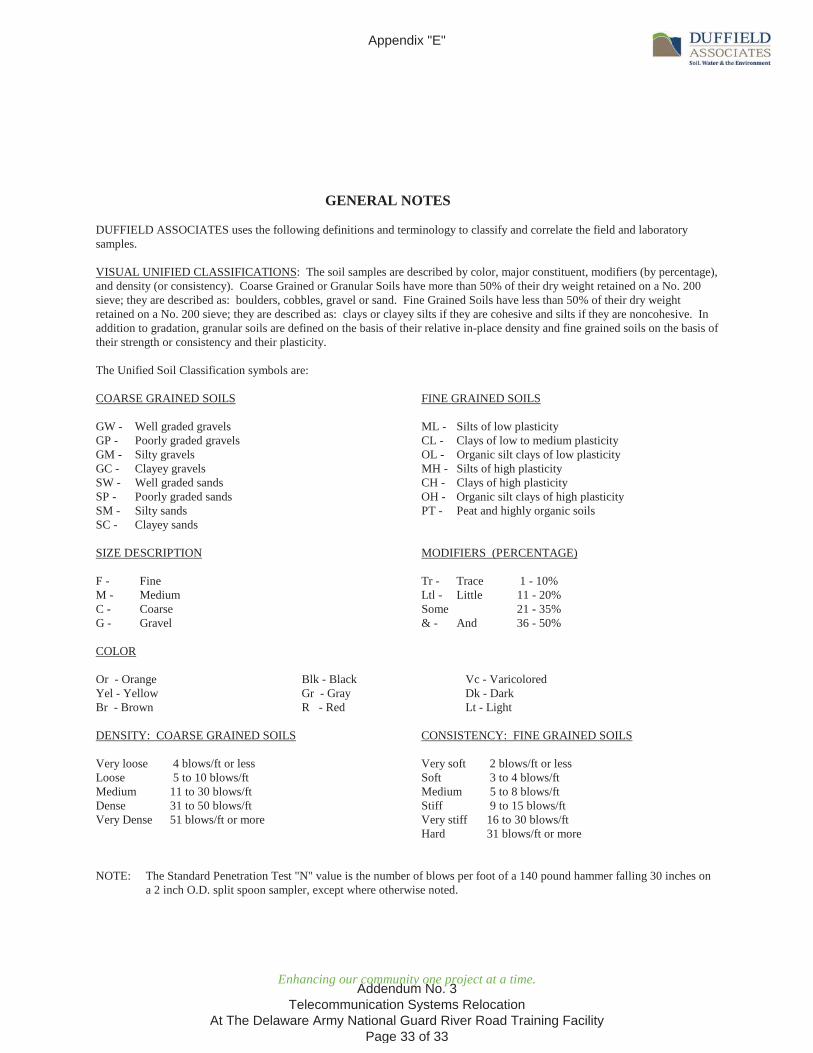
GENERAL NOTES
DUFFIELD ASSOCIATES uses the following definitions and terminology to classify and correlate the field and laboratory samples.
VISUAL UNIFIED CLASSIFICATIONS: The soil samples are described by color, major constituent, modifiers (by percentage), and density (or consistency). Coarse Grained or Granular Soils have more than 50% of their dry weight retained on a No. 200 sieve; they are described as: boulders, cobbles, gravel or sand. Fine Grained Soils have less than 50% of their dry weight retained on a No. 200 sieve; they are described as: clays or clayey silts if they are cohesive and silts if they are noncohesive. In addition to gradation, granular soils are defined on the basis of their relative in-place density and fine grained soils on the basis oftheir strength or consistency and their plasticity.
The Unified Soil Classification symbols are:
COARSE GRAINED SOILS FINE GRAINED SOILS
GW - Well graded gravels ML - Silts of low plasticity GP - Poorly graded gravels CL - Clays of low to medium plasticityGM - Silty gravels OL - Organic silt clays of low plasticityGC - Clayey gravels MH - Silts of high plasticitySW - Well graded sands CH - Clays of high plasticitySP - Poorly graded sands OH - Organic silt clays of high plasticitySM - Silty sands PT - Peat and highly organic soilsSC - Clayey sands
SIZE DESCRIPTION MODIFIERS (PERCENTAGE)
F - Fine Tr - Trace 1 - 10%M - Medium Ltl - Little 11 - 20% C - Coarse Some 21 - 35%G - Gravel & - And 36 - 50%
COLOR
Or - Orange Blk - Black Vc - VaricoloredYel - Yellow Gr - Gray Dk - DarkBr - Brown R - Red Lt - Light
DENSITY: COARSE GRAINED SOILS CONSISTENCY: FINE GRAINED SOILS
Very loose 4 blows/ft or less Very soft 2 blows/ft or lessLoose 5 to 10 blows/ft Soft 3 to 4 blows/ftMedium 11 to 30 blows/ft Medium 5 to 8 blows/ftDense 31 to 50 blows/ft Stiff 9 to 15 blows/ftVery Dense 51 blows/ft or more Very stiff 16 to 30 blows/ft
Hard 31 blows/ft or more
NOTE: The Standard Penetration Test "N" value is the number of blows per foot of a 140 pound hammer falling 30 inches on a 2 inch O.D. split spoon sampler, except where otherwise noted.
Appendix "E"
Addendum No. 3 Telecommunication Systems Relocation
At The Delaware Army National Guard River Road Training Facility Page 33 of 33


![C04 wireless telecommunication-systems[1]](https://static.fdocuments.us/doc/165x107/5581ebb4d8b42a67508b493e/c04-wireless-telecommunication-systems1.jpg)
![Introduction to telecommunication systems - Pure · -switching systems ... networks or into the upper levels (trunk network). ... Introduction to Telecommunication Systems ]99]](https://static.fdocuments.us/doc/165x107/5ad67e927f8b9a177c8e5e92/introduction-to-telecommunication-systems-pure-systems-networks-or-into-the.jpg)