Addendum - Kenya Electricity Generating Company No... · present 220 KV Overhead Lines connections...
80
Bid Document Addendum Reference Number: KGN-BDD-03-2019 _Addendum-01 PROCUREMENT OF PLANT DESIGN, SUPPLY AND INSTALLATION OF OLKARIA I UNITS 1, 2 AND 3 GEOTHERMAL POWER PLANT REHABILITATION PROJECT Subject: General Description Annex to: N/A Code: KGN-OLK01.TD.GEN.BD.002 (rev1.0) Document: “General Description" The “CIVIL CONSTRUCTION TECHNICAL SPECIFICATION SECTION A” document was erroneously duplicated in KGN-OLK01.TD.GEN.BD.002 (rev0.0). The document has now been revised to KGN-OLK01.TD.GEN.BD.002 (rev1.0) “GENERAL DESCRIPTION” KGN-OLK01.TD.GEN.BD.002 (rev1.0) supersedes KGN-OLK01.TD.GEN.BD.002 (rev0.0). Disregard KGN-OLK01.TD.GEN.BD.002 (rev0.0) in the Bid Documents. ACKNOWLEDGEMENT OF ADDENDUM NO.1 We, the undersigned hereby certify that the addendum is an integral part of the Tender Documents and the alterations set out in the addendum has been incorporated in the Tender Proposal. Signed........................................................................................................................................ Bidder........................................................................................................................................
Transcript of Addendum - Kenya Electricity Generating Company No... · present 220 KV Overhead Lines connections...
Bid Document
Addendum
Reference Number:
KGN-BDD-03-2019
_Addendum-01
PROCUREMENT OF PLANT DESIGN, SUPPLY AND INSTALLATION OF
OLKARIA I UNITS 1, 2 AND 3 GEOTHERMAL POWER PLANT REHABILITATION
PROJECT
Subject:
General Description
Annex to:
N/A
Code: KGN-OLK01.TD.GEN.BD.002 (rev1.0)
Document: “General Description"
The “CIVIL CONSTRUCTION TECHNICAL SPECIFICATION SECTION A” document
was erroneously duplicated in KGN-OLK01.TD.GEN.BD.002 (rev0.0). The document has
now been revised to KGN-OLK01.TD.GEN.BD.002 (rev1.0) “GENERAL DESCRIPTION”
KGN-OLK01.TD.GEN.BD.002 (rev1.0) supersedes KGN-OLK01.TD.GEN.BD.002
(rev0.0). Disregard KGN-OLK01.TD.GEN.BD.002 (rev0.0) in the Bid Documents.
ACKNOWLEDGEMENT OF ADDENDUM NO.1
We, the undersigned hereby certify that the addendum is an integral part of the Tender
Documents and the alterations set out in the addendum has been incorporated in the Tender
Proposal.
Signed........................................................................................................................................
Bidder........................................................................................................................................

GENERAL DESCRIPTION
EMPLOYER CODE
KGN-OLK01.TD.GEN.BD.002
Page 1 of 79
OLKARIA I UNITS 1, 2 AND 3 GEOTHERMAL
POWER PLANT REHABILITATION PROJECT
GENERAL DESCRIPTION
REV. DATE DESCRIPTION PREPARED CHECKED APPROVED
1.0 24/04/2019 Issued for Bid
R. Brogi R. Parri R. Papale
0.0 24/10/2017 Issued for Client approval
R. Brogi R. Parri R. Papale
PROJECT OLKARIA I
EMPLOYER CODE
OWNER PLANT TYPE LOT DOC PROGRESSIVE
REV.
KGN OLK01 TD GEN BD 002 0 1 . 0
CLASSIFICATION
PUBLIC COMPANY CONFIDENTIAL RESTRICTED
Total or partial reproduction and / or utilization of this document are forbidden without prior written authorization of KenGen.
GENERAL DESCRIPTION
EMPLOYER CODE
KGN-OLK01.TD.GEN.BD.002
Page 2 of 79
TABLE OF CONTENTS
1.PROJECT DESCRIPTION ...................................................................................................................... 5
1.1. BACKGROUND ....................................................................................................................................... 5
1.2. HELL'S GATE NATIONAL PARK CONTROL AND ADMINISTRATION .................................................................... 6
1.3. OPERATIONAL AREAS ............................................................................................................................. 6
2.SITE CONDITIONS .............................................................................................................................. 7
2.1. GENERAL ............................................................................................................................................. 7
2.2. SITE ACCESS ......................................................................................................................................... 7
2.3. COMMUNICATIONS ................................................................................................................................ 9
2.4. TOPOGRAPHY ....................................................................................................................................... 9
2.5. METEOROLOGY ..................................................................................................................................... 9 2.5.1. General ............................................................................................................................................. 9 2.5.2. Atmospheric Temperature .............................................................................................................. 10 2.5.3. Rain and Humidity .......................................................................................................................... 10 2.5.4. Wind distribution at Olkaria ........................................................................................................... 12 2.5.5. Air Quality ....................................................................................................................................... 13
2.6. SEISMIC FACTOR ................................................................................................................................. 14
2.7. SOIL AND GEOLOGY ............................................................................................................................. 14
3.HEALTH AND SAFETY ....................................................................................................................... 14
3.1. SAFETY OF PERSONNEL ......................................................................................................................... 14
3.2. WORK AT SITE .................................................................................................................................... 16
3.3. HEALTH AND SAFETY INDUCTION AND TRAINING ....................................................................................... 19
3.4. HAZARD MANAGEMENT ....................................................................................................................... 20
3.5. PROCEDURES FOR WORKING IN OPERATIONAL AREAS................................................................................ 20
3.6. DISPOSAL OF CONSTRUCTION WASTE ..................................................................................................... 21
3.7. REMOVAL AND DISPOSAL OF EXISTING EQUIPMENT................................................................................... 21
3.8. ELECTROMAGNETIC AND ENVIRONMENTAL COMPATIBILITY ......................................................................... 21
3.9. VIBRATIONS ........................................................................................................................................ 22
3.10. SAFETY STANDARDS AND PERSONAL PROTECTION ...................................................................................... 22
3.11. MEDICAL SERVICES AND FIRST AID .......................................................................................................... 22
3.12. EMERGENCY PROCEDURE ...................................................................................................................... 23
3.13. ACCESS AND INSPECTION STRUCTURE ...................................................................................................... 23
3.13.1. Platform, ladders and handrails ...................................................................................................... 23 3.13.2. Civil works ....................................................................................................................................... 24 3.13.3. Manholes ........................................................................................................................................ 25
3.14. SIGNS, SIGNALS AMD BARRICADES .......................................................................................................... 25
3.15. SAFETY ON PUBLIC ROADS ..................................................................................................................... 25
3.16. ILLUMINATION FOR NIGHT SHIFTS ........................................................................................................... 26
3.17. EARTHING, WET WORK AREAS, CONTROL OF ELECTRIC DISCHARGES .............................................................. 26
3.18. FIRE PRECAUTIONS ............................................................................................................................... 26
GENERAL DESCRIPTION
EMPLOYER CODE
KGN-OLK01.TD.GEN.BD.002
Page 3 of 79
3.18.1. Oil tank fire protection ................................................................................................................... 27
3.19. THERMAL INSULATION .......................................................................................................................... 27
4.QUALITY ASSURANCE ...................................................................................................................... 27
4.1. QUALITY ASSURANCE REQUIREMENTS..................................................................................................... 28
4.2. QUALITY ASSURANCE ARRANGEMENTS – QUALITY PLAN ............................................................................ 28
4.3. MONITORING BY THE EMPLOYER/PROJECT MANAGER ............................................................................... 29
4.4. CONTRACTOR QUALITY AUDITS .............................................................................................................. 29
4.5. CONTROL OF SUBCONTRACTORS ............................................................................................................ 30
4.6. INSPECTION AND TESTS ........................................................................................................................ 30
4.7. CONSTRUCTION/INSTALLATION PHASE .................................................................................................... 32
4.8. NON-CONFORMITIES ........................................................................................................................... 33
4.9. RECORDS ........................................................................................................................................... 34
4.10. METHOD STATEMENTS ......................................................................................................................... 34
4.11. QUALITY CONTROL PLAN (QCP) ............................................................................................................ 34
4.12. TESTING AND PERFORMANCE GUARANTEED ............................................................................................. 34
5.PROJECT MANAGEMENT ................................................................................................................ 35
5.1. IMPLEMENTATION SCHEDULE ................................................................................................................. 35 5.1.1. Project Schedule with Proposal ...................................................................................................... 35 5.1.2. Contract Project Schedule .............................................................................................................. 35
5.2. PROGRESS REPORT .............................................................................................................................. 36
5.2.1. Monthly Progress Report ................................................................................................................ 36 5.2.2. Weekly Summary Report ................................................................................................................ 39 5.2.3. Meetings ......................................................................................................................................... 39
5.3. WORKS COORDINATION ........................................................................................................................ 40 5.3.1. Cooperation with the Employer and other Contractors ................................................................. 40 5.3.2. Site Construction Facilities .............................................................................................................. 40
6.DESIGN AND ENGINEERING ............................................................................................................ 41
6.1. BID DOCUMENTS ................................................................................................................................ 41
6.1.1. General ........................................................................................................................................... 41 6.1.2. Documents Submission with Proposal ........................................................................................... 42
6.2. DOCUMENTS AFTER CONTRACT AWARD.................................................................................................. 45 6.2.1. General ........................................................................................................................................... 45
6.3. DOCUMENTS CHARACTERISTICS ............................................................................................................. 48 6.3.1. Size and template ........................................................................................................................... 48 6.3.2. Revision numbering ........................................................................................................................ 49 6.3.3. Tagging system ................................................................................................................................ 50 6.3.4. Symbols and Codes and Standards ................................................................................................. 50 6.3.5. Units and Scale Ratios..................................................................................................................... 50 6.3.6. Quality ............................................................................................................................................ 50 6.3.7. Language and System of Unit of Measurement ............................................................................. 51
6.4. DOCUMENT SUBMISSION SYSTEM .......................................................................................................... 51 6.4.1. Control ............................................................................................................................................ 51
GENERAL DESCRIPTION
EMPLOYER CODE
KGN-OLK01.TD.GEN.BD.002
Page 4 of 79
6.4.2. Identification .................................................................................................................................. 51 6.4.3. Verification ..................................................................................................................................... 52 6.4.4. Engineering Representative ............................................................................................................ 52 6.4.5. Documentation Schedule ............................................................................................................... 52
6.5. DESIGN REVIEW .................................................................................................................................. 53 6.5.1. Design Review Meetings ................................................................................................................. 55 6.5.2. Design Discrepancies ...................................................................................................................... 55
6.6. DOCUMENTS CONTENTS ....................................................................................................................... 56
6.7. REPORTS ............................................................................................................................................ 57
6.7.1. General ........................................................................................................................................... 57
6.8. SCHEDULE FOR DELIVERY OF DOCUMENTS ................................................................................................ 62 6.8.1. Data and Drawings to be Submitted Within One (1) Month .......................................................... 62 6.8.2. Data and Drawings to be Submitted Within Two (2) Months ......................................................... 63 6.8.3. Data and Drawings to be Submitted Within Three (3) Months ...................................................... 64 6.8.4. Data and Drawings to be Submitted Within Four (4) Months ........................................................ 64 6.8.5. Before commencement of manufacture, three (3) sets of: ............................................................ 65
6.9. REVISION OF CONTRACTOR’S DRAWINGS AT SITE ...................................................................................... 67
6.9.1. As Built Drawings ............................................................................................................................ 68
6.10. PROCEDURES ...................................................................................................................................... 68
6.10.1. Erection Procedure ......................................................................................................................... 68 6.10.2. Pre-Commissioning Procedures ...................................................................................................... 68 6.10.3. Commissioning Procedure .............................................................................................................. 69
7.ERECTION, SUPERVISION AND CHECKING OF WORK ON SITE ........................................................ 70
7.1. GENERAL ........................................................................................................................................... 70
7.2. OVERALL TIME SCHEDULE ..................................................................................................................... 71
7.3. SUBCONTRACTED PLANT, MATERIALS AND LABOUR .................................................................................. 71
7.4. ACCESS TO MANUFACTURERS' WORKS .................................................................................................... 71
7.5. TOOLS & EQUIPMENT FOR ERECTION, INSTALLATION & COMMISSIONING ..................................................... 71
7.6. CONTRACTOR’S EMPLOYEES .................................................................................................................. 71
7.7. ALCOHOLIC LIQUOR OR DRUGS .............................................................................................................. 72
8.TRAINING ........................................................................................................................................ 72
8.1. BASIC CRITERIA .................................................................................................................................... 72
8.2. OVERSEAS COURSES ............................................................................................................................. 73 8.2.1. Personnel involved ......................................................................................................................... 73 8.2.2. General subjects ............................................................................................................................. 74 8.2.3. Specific subjects ............................................................................................................................. 74 8.2.4. Costs ............................................................................................................................................... 75
8.3. ON SITE COURSES ................................................................................................................................ 75 8.3.1. Personnel involved ......................................................................................................................... 75 8.3.2. Training program ............................................................................................................................ 75 8.3.3. Costs ............................................................................................................................................... 77
8.4. HV SUBSTATION .................................................................................................................................. 77

GENERAL DESCRIPTION
EMPLOYER CODE
KGN-OLK01.TD.GEN.BD.002
Page 5 of 79
1. PROJECT DESCRIPTION
The aim of this document is to provide a general description and technical specifications for the
rehabilitation of the entire Olkaria I single flash geothermal power plant, including the steamfield and
HV substation (hereinafter called Project).
1.1. BACKGROUND
The Employer, the Kenya Electricity Generating Company Limited (KenGen), generates electricity
from the Olkaria I, II, IV, 1AU power plants, OW914 and OW37/39 Wellhead Stations, at the Greater
Olkaria Geothermal Field, located in the Rift Valley of Kenya within the Hell's Gate National Park and
approximately 120 km north-west of Nairobi.
These power plants generate a total of 605.8 MWe corresponding to:
Olkaria I (Olkaria East Field) produce 45 MWe (Mega-Watt electrical);
Olkaria II (Olkaria North-East Field) produce 105 MWe;
Olkaria IV produce 140 MWe (Olkaria Domes Field);
Olkaria 1AU produce 140 MWe ;
The OW914 Wellhead Station is a small power plant unit that concentrates other small
power plant units (914, 915 and 919) with a total generation capacity of 47.8 MWe.
The OW37/39 Wellhead Station have a total generating capacity of 20 MWe.
These Power Plants provide base load service to the Kenyan power supply network thought the
present 220 KV Overhead Lines connections to Suswa Substation.
The existing Olkaria I Geothermal Power Plant and 132 kV electrical substation, located at the Olkaria
Geothermal field in the Rift Valley, was established in 1980. The installed capacity of the Power Plant
is 45MW, with 3 units of 15 MW each. The electrical substation had, initially, two bays for generator
transformers (one transformer with double secondary, 36/18/18 MVA, to connect generator unit 1
and 2, and another single transformer, 18 MVA, for generator unit 3), and two bays for transmission
lines (to OW 37 substation and to Naivasha/Olkaria IAU substations).
The entire plant has experienced normal wear and tear over the 32 years of operation. Most
equipment of the Project (and substation) is no longer in production (obsolete) and thus the
acquisition of spare parts becomes difficult.
GENERAL DESCRIPTION
EMPLOYER CODE
KGN-OLK01.TD.GEN.BD.002
Page 6 of 79
The Employer has assessed the necessity to upgrade and rehabilitate the existing power plant, steam
field and substation and intends to structure the entire rehabilitation works into one main contract.
Site Location
PROJECT DATA
Project name OLKARIA I Units 1,2 and 3 Geothermal Power Plant
Rehabilitation Project
Employer KENGEN
Target plant start-up /COD TO BE DEFINED
Expected Net Power
(at design condition) not less than 50.7 MWe
SITE DATA
Country Kenya
County Nakuru
Location Greater Olkaria geothermal area
Coordinates 36°18'32.0"East – 0°53'3450"South
Elevation Above Sea Level 1930 m
All activities and works shall be done in agreements with the prescription done by National
Environment Management Authority (NEMA) with the environmental management and co-
ordination act environmental impact assessment license No: NEMA /EIA/PSL/558.
1.2. HELL'S GATE NATIONAL PARK CONTROL AND ADMINISTRATION
The Hell's Gate National Park is controlled and administered by the Kenya Wildlife Service (KWS). All
Works associated with this project shall comply fully with the requirements of KWS where it impacts
upon operation of the National Park.
1.3. OPERATIONAL AREAS
There are Operational Areas near the project site, these being Olkaria I geothermal power plant and
associated steamfield and transmission facilities, OW37, Naivasha/Olk IAU Substation, Transmission
GENERAL DESCRIPTION
EMPLOYER CODE
KGN-OLK01.TD.GEN.BD.002
Page 7 of 79
Lines, and other sites, that could be under the control of the Employer's other contractors. These
Operational Areas are controlled by the Employer, Kenya Power and Lighting Company Ltd (KPLC),
Kenya Wildlife Serviceor other contractors.
It is noted that part of the project works will be undertaken within Operational Areas and, at times,
require connection to, or interfacing with, existing facilities or Portions that have already been
accepted by the Employer. The Contractor shall not cause any unplanned outages or unauthorized
disruption to the operational plants.
The Operational Areas include, but are not limited to the following:
The sites of the Olkaria I Power Plant and Substation, contained within the perimeter
fences, which are under the control of the Employer and KPLC
The wellpads and process areas of the Olkaria I steamfield each within perimeter
fences, which are under control of the Employer and KPLC
The steamfield cross country steam, brine and condensate pipework with associated
access tracks etc within the general areas of the Hell's Gate National Park, which are
under control of the Employer and the KWS
The electrical transmission system within the general area of the Hell's Gate National
Park which is under control of KPLC, the Employer and the KWS
The electrical transmission system within a wayleave traversing private land from the
boundary of Hell's Gate National Park
Any Portions of the Works that have been accepted by the Employer.
2. SITE CONDITIONS
2.1. GENERAL
The technical data included in this specification such as the site location, topography, meteorological
data, soil and geology, tide level data, “as built” documentation, etc., are for the Contractor’s
information only. The Employer assumes no responsibility for accuracy of these technical data. The
Contractor shall perform independent investigations including appropriate soil investigation, route
survey, etc., as necessary to ensure accuracy of these technical data plus any additional investigation
required for the substation and lines design.
2.2. SITE ACCESS
The following information is only for reference and preliminary.
GENERAL DESCRIPTION
EMPLOYER CODE
KGN-OLK01.TD.GEN.BD.002
Page 8 of 79
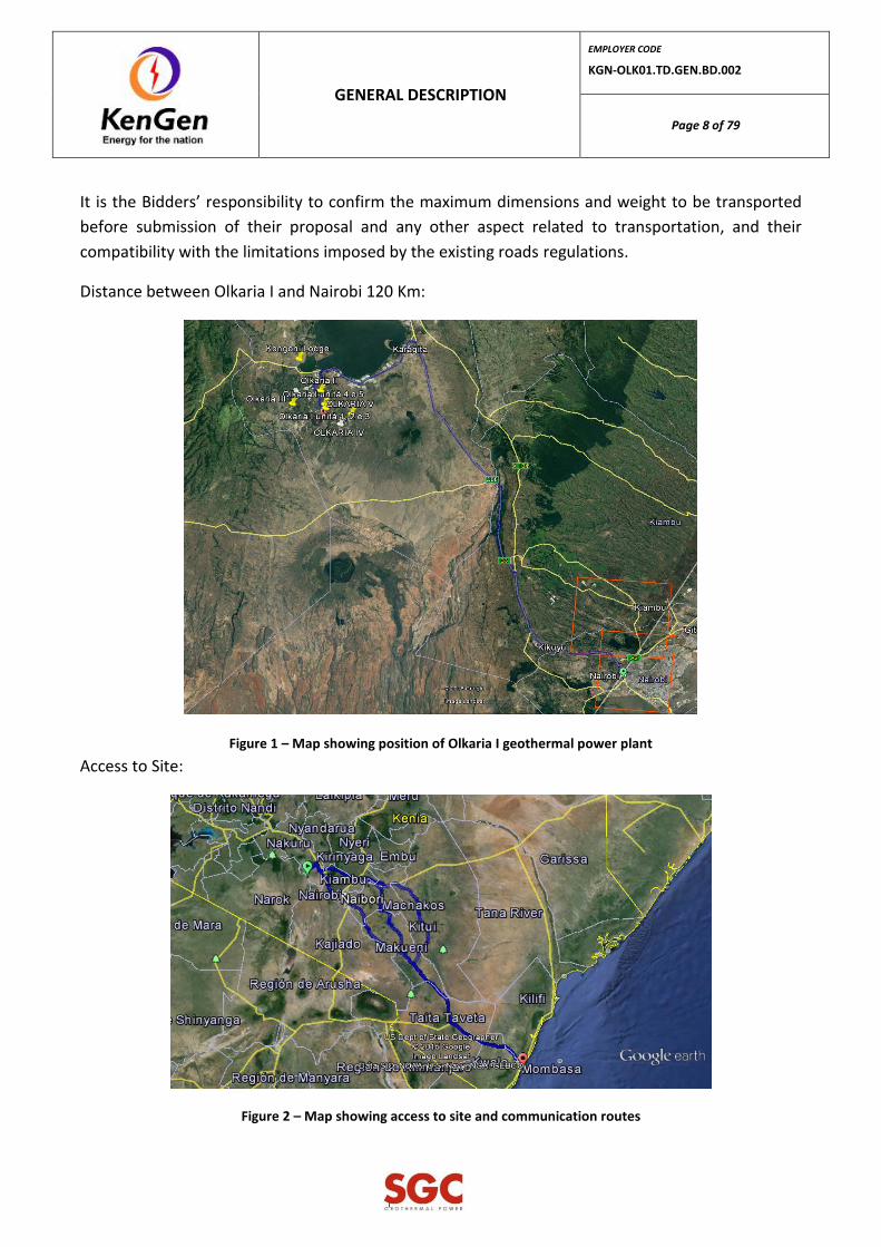
It is the Bidders’ responsibility to confirm the maximum dimensions and weight to be transported
before submission of their proposal and any other aspect related to transportation, and their
compatibility with the limitations imposed by the existing roads regulations.
Distance between Olkaria I and Nairobi 120 Km:
Figure 1 – Map showing position of Olkaria I geothermal power plant
Access to Site:
Figure 2 – Map showing access to site and communication routes

GENERAL DESCRIPTION
EMPLOYER CODE
KGN-OLK01.TD.GEN.BD.002
Page 9 of 79
Mombasa is the main commercial port in Kenya and meets international standards.
The image above shows the access roads from Mombasa port to the project site. The distance from
the Port to Project Site is approximately 600km
2.3. COMMUNICATIONS
Kenya has a progressive communications network for domestic and international telephone and fax
services. International direct dial is available in most cities and towns. For remote destinations that
do not offer these services, you may have access to mobile services or even radio links for relaying
messages as needed.
2.4. TOPOGRAPHY
A topographical survey conducted for the project site is included in the Appendix C – Topographic
Survey.
2.5. METEOROLOGY
2.5.1. General
Climate - The Project area lies within the Eco-climatic Zone IV that is described as environmentally
fragile and prone to land degradation.
The baseline climate data recorded by the Employer has been evaluated from a model known as
TAPM, and are discussed in succeeding sections below.
Ambient Conditions
Value Units
Dry Bulb Temperature
Range 1.0 – 35.0 °C
Wet Bulb Temperature
Design 18.0 °C
Range 1.0 – 28.5 °C
GENERAL DESCRIPTION
EMPLOYER CODE
KGN-OLK01.TD.GEN.BD.002
Page 10 of 79
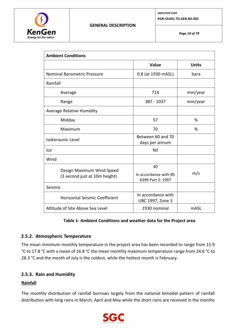
Ambient Conditions
Value Units
Nominal Barometric Pressure 0.8 (at 1930 mASL) bara
Rainfall
Average 714 mm/year
Range 387 - 1037 mm/year
Average Relative Humidity
Midday 57 %
Maximum 70 %
Isokeraunic Level Between 60 and 70
days per annum
Ice Nil
Wind
Design Maximum Wind Speed (3 second just at 10m height)
40
In accordance with BS 6399 Part 2: 1997
m/s
Seismic
Horizontal Seismic Coefficient In accordance with UBC 1997, Zone 3
Altitude of Site Above Sea Level 1930 nominal mASL
Table 1- Ambient Conditions and weather data for the Project area
2.5.2. Atmospheric Temperature
The mean minimum monthly temperature in the project area has been recorded to range from 15.9
°C to 17.8 °C with a mean of 16.8 °C the mean monthly maximum temperature range from 24.6 °C to
28.3 °C and the month of July is the coldest, while the hottest month is February.
2.5.3. Rain and Humidity
Rainfall
The monthly distribution of rainfall borrows largely from the national bimodal pattern of rainfall
distribution with long rains in March, April and May while the short rains are received in the months

GENERAL DESCRIPTION
EMPLOYER CODE
KGN-OLK01.TD.GEN.BD.002
Page 11 of 79
of October and November. Generally, the floor of the Rift Valley has lower rainfall than the flanking
highlands. This area experiences a double rain shadow effect from the west and east flanking
escarpments (Mau and Aberdare Range I Kananga respectively).
Rainfall in the project area and its environs is generally low, recording an average of 634 mm annually.
Evaporation exceeds precipitation almost throughout the year. It ranges from approximately 700 mm
per year in areas around the lake to approximately 1,000 mm per year on higher ground, with
variations from year to year.
The baseline daily rainfall is measured at four sites; X2 Campsite, Site, North East Olkaria and Lake
View. Data for the 20-year period between January 1996 and December 2016 has been analyzed to
show the mean monthly rainfall values over the last 20 years in the project area.
The X2, Site, North East Olkaria and Lake View have shown little spatial difference in the mean annual
rainfall. The mean annual rainfalls for the four sites are as follows: 21.17, 20.23, 15.88, and 19.74,
respectively (Environmental and Social Impact Assessment Study Report (ESIA), Source KenGen’s
Olkaria)
Humidity
KenGen Olkaria made the measurements of the relative humidity in between 9AM and 3PM as
indicated in the Table 3-1, below. Based on the data there is modest variation in the relative humidity
across seasons. Normally diurnal variation with higher values are observed in the cooler morning
times; while lower values in the warmer afternoon period at 3PM.
The data provided, contains ambient measured temperature and relative humidity registered at 9
am and 3 pm (9 and 15) and only in working days, not in weekends.
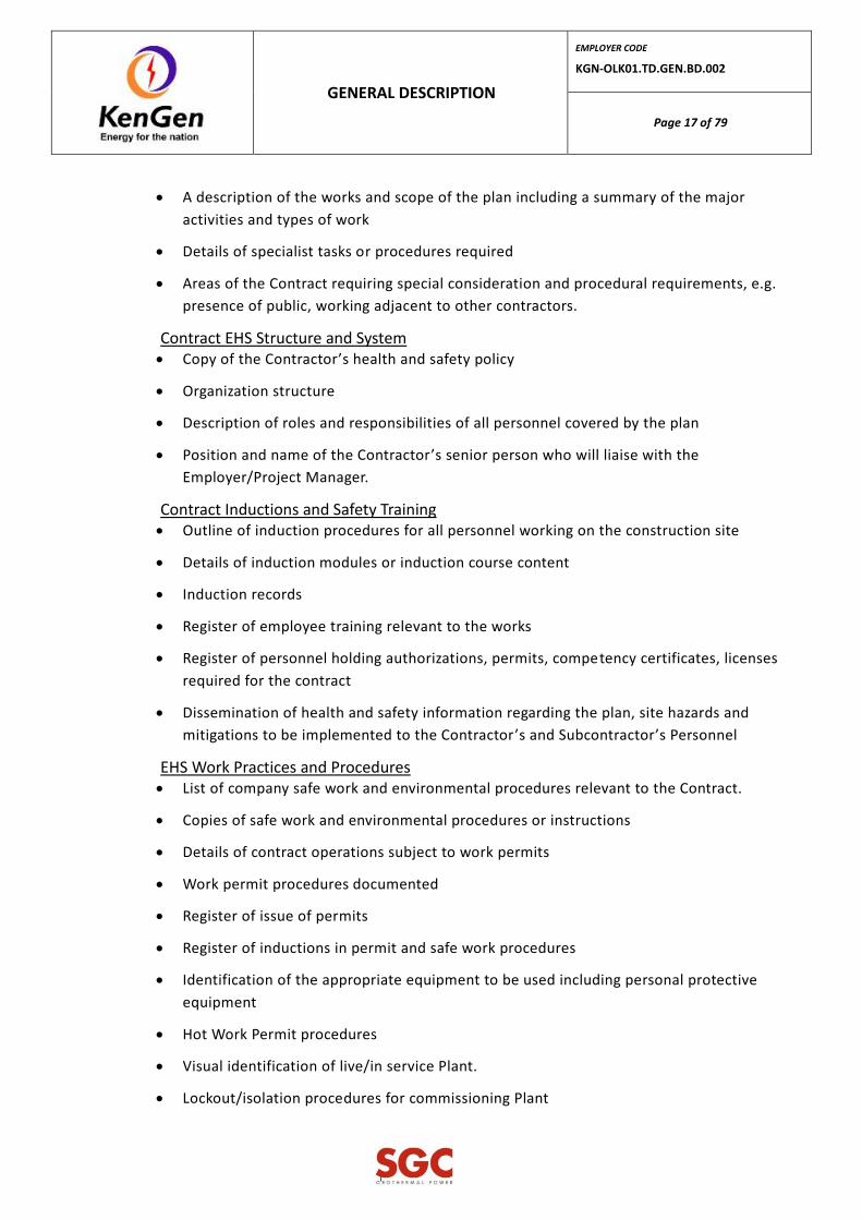
No information is registered for the night-time. Annual proportion of the year under a given wet-bulb
temperature is given in Figure 3-2.
Over half of the total days (57percent) across the year at midday has an ambient wet bulb
temperature equal or below 15°C. 85% of the days has ambient wet bulb at noon equal to or below
16°C and 94% equal to or below 17°C.
Temperature and relative humidity readings for Olkaria:
Period Relative Humidity (%)
Range Average
09.00 hrs 6 - 100 73.5
GENERAL DESCRIPTION
EMPLOYER CODE
KGN-OLK01.TD.GEN.BD.002
Page 12 of 79
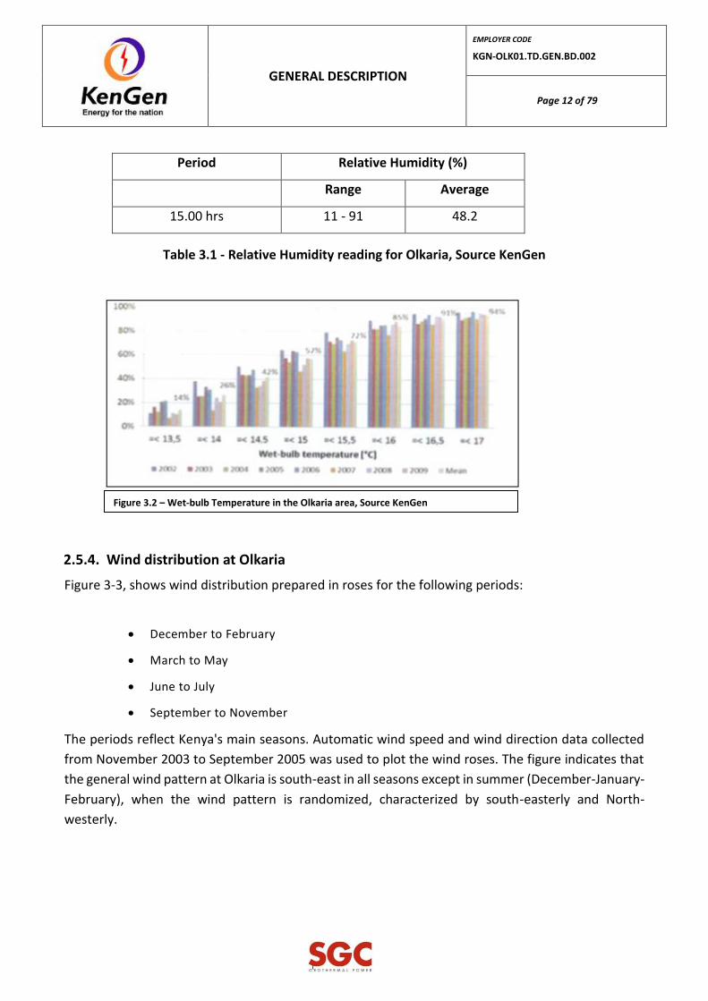
Period Relative Humidity (%)
Range Average
15.00 hrs 11 - 91 48.2
Table 3.1 - Relative Humidity reading for Olkaria, Source KenGen
2.5.4. Wind distribution at Olkaria
Figure 3-3, shows wind distribution prepared in roses for the following periods:
December to February
March to May
June to July
September to November
The periods reflect Kenya's main seasons. Automatic wind speed and wind direction data collected
from November 2003 to September 2005 was used to plot the wind roses. The figure indicates that
the general wind pattern at Olkaria is south-east in all seasons except in summer (December-January-
February), when the wind pattern is randomized, characterized by south-easterly and North-
westerly.
Figure 3.2 – Wet-bulb Temperature in the Olkaria area, Source KenGen

GENERAL DESCRIPTION
EMPLOYER CODE
KGN-OLK01.TD.GEN.BD.002
Page 13 of 79
2.5.5. Air Quality
Gas emissions from the existing KenGen Olkaria power stations predominantly consists of carbon
dioxide (95.1 %) and hydrogen sulphide (4.4%). The other gases, which include hydrogen, methane,
nitrogen and oxygen, form 0.5% (wUwt) of the total non-condensable gas fraction. Total geo-gas
forms about 2% of geothermal effluent (Sinclair Knight and partners, 1994).
This is discharged to the atmosphere.
Carbon dioxide and methane are greenhouse gases that have global climate impacts. Apart from
being a greenhouse gas, carbon dioxide combines with moisture in the air to form carbonic acid,
which is a weak acid. Depending on the amount of the acid formed, pH values of rainwater may be
lowered.
Normal precipitation has pH values between 5.6 and 5.65 due to the presence of carbon dioxide in
the atmosphere. Long exposure of high concentration of carbon dioxide has serious impact on human
beings.

GENERAL DESCRIPTION
EMPLOYER CODE
KGN-OLK01.TD.GEN.BD.002
Page 14 of 79
Studies have shown that exposure of various concentrations of carbon dioxide have effects on human
breathing (Kubo et al, 1999).
For more details about air quality see General Technical Requirement Document (code KGN-OLK01-
TDM.GEN.BD.004).
2.6. SEISMIC FACTOR
Olkaria is situated on the East African Rift Valley in a wide zone of active volcanic fault lines that
extend north-south in eastern Africa for more than 3,000 km from Ethiopia in the north to the
Zambezi river in the south.
Horizontal seismic coefficient; in accordance with UBC 1997, zone three (3).
2.7. SOIL AND GEOLOGY
The Olkaria Geothermal Field lies within the Rift Valley of Kenya. The geology is dominated near
surface by rhyolite volcanoes which include deposits of rhyolite and obsidian blocks, bedded ash and
lapilli deposits and weathered massive pumiceous deposits likely formed by pyroclastic flow.
The site has some near surface geothermal activity as can be seen from fumeroles occurring near
hobleys volcano, the area is faulted and folded with steep ridge lines and escarpments. Steep sided,
deep gullies have been eroded through pumice deposits and there are wide areas with low relief
where there has been an accumulation of windblown weathered volcanic ash (loess).
A preliminary geotechnical investigation into the subsoil conditions for the proposed Site at Olkaria I
is included in the Appendix D – Geotechnical Studies.
3. HEALTH AND SAFETY
3.1. SAFETY OF PERSONNEL
Maximum safety, consistent with good erection practice, must be afforded to personnel directly
engaged on this Contract, or who in the normal course of their occupation find it necessary to utilize
temporary works erected by the Contractor or frequent the working area. Reasonable measures shall
be taken to afford adequate protection against material falling from a higher level onto personnel
below.

GENERAL DESCRIPTION
EMPLOYER CODE
KGN-OLK01.TD.GEN.BD.002
Page 15 of 79
It is the objective of the Employer that this project be designed, constructed, started-up,
commissioned and operated without causing injury or death to any personnel (Contractor's or other
parties) or damage to equipment.
The Contractor shall be responsible for the management of health and safety on the construction site
until is handed over to the Employer/Project Manager.
The Contractor shall develop and submit within 30 days of the Commencement Date, a
comprehensive Health and Safety Plan for the execution of the Works for review by the Project
Manager. The Health and Safety Plan shall include the requirements of the Employer's Safety
Guidelines.
A copy of the Employer's Safety Guidelines is included in the Supplementary Information under
Section VI, Chapter SUPPLEMENTARY INFORMATION, Appendix I.
Particular care shall be taken during work at places where parts of the Project are operational or may
be energized, and places where part of the substation is energized. No testing or other work on
existing apparatus or that has been delivered to Site and which is liable to be electrically charged
from any source shall be permitted except under a “Permit to Work” which will be issued for the
purpose by Employer and/or Operating Project Managers. At the completion of the Contract Works
the Employer/Project Manager shall undertake an inspection to ensure the operational safety of the
substations and overhead electricity transmission lines. For this purpose, the Contractor shall jointly
undertake with the Employer/Project Manager and/or KETRACO an inspection of the Contract Works.
The cost of any re-inspection occasioned by non-compliance with the Specification by the Contractor
shall be borne by the Contractor.
Prior to any activities being undertaken outside of the Contractors home office location(s) Health and
Safety plans covering the activities shall be completed and submitted to the Project Manager for
review.
The Contractor shall ensure that all of the Contractor's and Contractor's subcontractors' personnel
comply with the requirements of the Health and Safety Plan.
In addition, the Contractor shall comply with the Kenyan health and safety legislation the health and
safety requirements of the Employer, KPLC/KETRACO and the Kenya Wildlife Service, as applicable,
for all activities and works performed in the Operational Areas.
The Contractor shall convene and chair a monthly health and safety meeting to be attended by the
Employer/Project Manager and lead health and safety personnel from the Contractor and
subcontractors engaged on site. The Contractor shall distribute minutes of these meetings within
three days.

GENERAL DESCRIPTION
EMPLOYER CODE
KGN-OLK01.TD.GEN.BD.002
Page 16 of 79
The Contractor shall participate in inspections and audits conducted by the Employer/Project
Manager and shall respond to corrective actions arising from audit and inspection findings in a timely
manner. The Contractor’s records shall be available for inspection by the Employer/Project Manager.
The Contractor shall appoint a full time dedicated health and safety professional who is appropriately
qualified and has the authority for:
Implementing and maintaining the Contractors Health and Safety Plan;
Ensuring the health and safety systems and processes are implemented, maintained and
complied with by the Contractor and Subcontractors;
Reporting on the health and safety performance of the Contractor and Subcontractors;
Hazard management and mitigation by the Contractor and Subcontractors;
Incident, accident prevention and mitigation;
Incident investigation
Maintaining records
Conducting inspections, identifying corrective actions
Ensuring compliance to the Employer’s health and safety requirements;
Ensuring compliance to the Contractors health and safety plan.
The Contractor’s lead health and safety person shall be point of contact for the
Employer/Project Manager in regard to health and safety matters.
3.2. WORK AT SITE
Before any work commences at the Site, the Contractor shall submit a Health and Safety Plan for its
employees and Subcontractors to the Project Manager for review and approval. This plan shall
incorporate the requirements of any other Governmental Authorities having legal jurisdiction in such
matters.
The Contractor shall carry out all activities in accordance with the submitted health and safety plan.
Copies of the health and safety plan(s) shall be maintained at all locations where activities related to
the Project are being undertaken.
The plan shall include in all the arrangements required to ensure the health and safety of all
Personnel undertaking and affected by the Works.
As a minimum, the Plan shall include the following:
Contract Description
GENERAL DESCRIPTION
EMPLOYER CODE
KGN-OLK01.TD.GEN.BD.002
Page 17 of 79
A description of the works and scope of the plan including a summary of the major
activities and types of work
Details of specialist tasks or procedures required
Areas of the Contract requiring special consideration and procedural requirements, e.g.
presence of public, working adjacent to other contractors.
Contract EHS Structure and System Copy of the Contractor’s health and safety policy
Organization structure
Description of roles and responsibilities of all personnel covered by the plan
Position and name of the Contractor’s senior person who will liaise with the
Employer/Project Manager.
Contract Inductions and Safety Training Outline of induction procedures for all personnel working on the construction site
Details of induction modules or induction course content
Induction records
Register of employee training relevant to the works
Register of personnel holding authorizations, permits, competency certificates, licenses
required for the contract
Dissemination of health and safety information regarding the plan, site hazards and
mitigations to be implemented to the Contractor’s and Subcontractor’s Personnel
EHS Work Practices and Procedures List of company safe work and environmental procedures relevant to the Contract.
Copies of safe work and environmental procedures or instructions
Details of contract operations subject to work permits
Work permit procedures documented
Register of issue of permits
Register of inductions in permit and safe work procedures
Identification of the appropriate equipment to be used including personal protective
equipment
Hot Work Permit procedures
Visual identification of live/in service Plant.
Lockout/isolation procedures for commissioning Plant

GENERAL DESCRIPTION
EMPLOYER CODE
KGN-OLK01.TD.GEN.BD.002
Page 18 of 79
Formal written permit to work system listing lockout points and identifying Plant to be
isolated
Copies of other relevant safe work procedures
Risk Assessment Identification and ranking of existing and potential construction hazards and risks
Procedures for the elimination, isolation or mitigation of hazards and risks
Workplace Environment, Health and Safety Inspections Procedures for monitoring and enforcing the plan including frequency of inspections,
inspection
checklists and close-out of actions arising from inspections
The maintenance of a register of hazards for the Site
Reporting of hazards
Emergency Procedures Emergency procedures including all necessary contact details for emergency and
support personnel/services
First aid procedures including contact details for all first aid staff
Fire prevention and evacuation procedures
Incident Reporting Procedure for incident (near-miss) and accident investigations and reporting including:
− Notification to the Employer/Project Manager within 1 hour of all serious harm
accidents occurring
− Notification to the Employer/Project Manager of all other incidents/accidents within
24 hrs;
− Delivery to the Employer/Project Manager fully documented reports within 48hrs.
− The report shall include the problem, root cause and corrective actions to prevent
recurrence.
Accident register
Health and Safety Performance Monitoring Procedure for review of the plan
Audit procedure
Records to be maintained on site
Register of Project and any inspection records, licenses, etc.
Material safety data sheets for all hazardous goods and chemicals brought onto the Site

GENERAL DESCRIPTION
EMPLOYER CODE
KGN-OLK01.TD.GEN.BD.002
Page 19 of 79
Reporting requirements
Contractor’s on-site health and safety committee
Other Management of visitors
Regular site toolbox meetings shall be held to ensure all Personnel are aware of the current activities
on the Site as they affect health and safety and to maintain safety and safe working practices at the
top of all Personnel’s mind.
Records shall be maintained to include licenses or certificates of competency held by personnel
appropriate to site activities, e.g. vehicle license, crane operation, rigger.
A register of plant and equipment and inspection records shall be kept. The Contractor’s attention is
drawn to the requirements of the Occupational Safety and Health Act 2007 in this regard.
3.3. HEALTH AND SAFETY INDUCTION AND TRAINING
The Contractor shall ensure that all of the Contractor's Personnel shall have participated in a site
induction training program before they commence work at Site. The induction program shall ensure
that the Personnel inducted are fully familiar with the health and safety plan and their responsibilities
under that plan.
No Personnel shall be allowed to work at the Site without prior a complete induction training taking
place. Personnel who have not successfully completed the induction training shall be escorted under
direct and continuous supervision by a person who holds the relevant and current induction and
health and safety training competences.
Health and safety and induction training records shall be maintained for all Personnel working on
Site. These records shall be made available to the Employer and/or Project Manager on request.
The Contractor shall submit the health and safety induction training package to the Employer for
review 14 days prior to the first presentation and thereafter keep the Employer informed of updates
and changes.
The Contractor shall ensure no Personnel perform a task on their own for which they are not trained
or competent, unless that person is working under the direct and continuous supervision of a person
who is trained or competent. The Contractor shall demonstrate to the Employer upon request,
evidence of any Contractor or Subcontractor Personnel training/competencies related to a work task.

GENERAL DESCRIPTION
EMPLOYER CODE
KGN-OLK01.TD.GEN.BD.002
Page 20 of 79
3.4. HAZARD MANAGEMENT
The Contractor shall maintain a comprehensive hazard management system covering all work
activities on and off the Site, in order to systematically identify, assess, and control hazards at the
site that could cause harm or serious harm.
Hazard identification shall take full account of any special requirements concerning the nature,
handling and storage of hazardous materials including fuel oils, gases and chemicals etc., and provide
plant, equipment, buildings, handling procedures, material safety data sheets and other services
accordingly.
Hazards shall be reviewed at least weekly and all updates shall be clearly communicated to all
personnel on the site.
Output from the hazard management system shall be included in the monthly report.
The hazard management system shall be made available to the Employer/Project Manager on
request in a fully auditable format.
3.5. PROCEDURES FOR WORKING IN OPERATIONAL AREAS
All work in Operational Areas shall comply with the Employer's permit to work systems.
All access to Operational Areas will be controlled by the Employer. "Access Permits" will be issued to
the Contractor's employees who require entry to Operational Areas.
Operational Areas that are controlled by KPLC, will also be controlled by "Access Permits" issued by
KPLC in addition to "Access Permits" issued by the Employer. The requirements of KPLC shall be
deemed to be the requirements of the Employer.
The Contractor's employees carrying out work in Operational Areas shall attend a one-day training
course on the Employer's permit to work system. The Contractor shall provide a schedule of
employees that will require training and a timetable for training.
All isolations required for work in Operational Areas will be carried out by the Employer and shall be
checked by the Contractor before the issue of the permit to work.
For all activities in Operational Areas the Contractor shall give a minimum 5 days advance notice.
All activities or work required for the execution of the Works that involves a "risk of trip" for the
existing plant shall be coordinated with the Employer and KPLC, where appropriate, and shall have a
minimum of 21 days advance notice.
GENERAL DESCRIPTION
EMPLOYER CODE
KGN-OLK01.TD.GEN.BD.002
Page 21 of 79
The Contractor shall co-operate with the Employer and KPLC to co-ordinate all works which require
shutdowns with any of the Employers planned shutdowns and to ensure that any other shutdowns
are kept to a minimum.
The Employer reserves the right to cancel any shutdowns for operational reasons. If a shutdown is
cancelled, the Employer will advise the Contractor of the re-scheduled planned shutdown date.
3.6. DISPOSAL OF CONSTRUCTION WASTE
Construction waste shall be disposed of in the following locations:
Scrap metal – The Contractor shall transport the scrap metal to designated areas within
Olkaria as directed by the Employer/Project Manager.
The Contractor shall transport and bury the cementitious slurry wastes to designated
areas within Olkaria as agreed with the Employer/Project Manager.
Hazardous materials shall be disposed of in strict accordance with local regulat ions.
Waste other than scrap metal, cementitious slurries and hazardous materials shall be
disposed to designated areas within Olkaria as directed by the Employer/Project
Manager.
Contractor shall follow guidance from environment disposal of construction waste.
3.7. REMOVAL AND DISPOSAL OF EXISTING EQUIPMENT
Dismantling of all equipment’s and materials, related with the Project, that will not be used after this
project, shall be properly dismantled, maintained and delivered to KENGEN in a place indicated by
KENGEN.
3.8. ELECTROMAGNETIC AND ENVIRONMENTAL COMPATIBILITY
Unless otherwise specified in the Technical Specifications the following prescriptions shall apply to
the protection, control and monitoring equipment.
Electromagnetic Compatibility Immunity requirements shall be in accordance with the latest IEC CENELEC Standard. Thermal Compatibility As for the Thermal Compatibility, the following prescriptions shall apply (IEC 68.2.1 IEC 68.2.2, IEC 68.2.3, IEC 68.2.48, IEC 68.2.56, IEC 68.5.2, etc.). Mechanical Compatibility As for the Mechanical Compatibility the following prescriptions shall apply:
Vibration (IEC 654.3, IEC 255.21.2, etc.): 5 - 8 Hz 3,5 mm d.a. 8 - 150 Hz 1g

GENERAL DESCRIPTION
EMPLOYER CODE
KGN-OLK01.TD.GEN.BD.002
Page 22 of 79
Shock (IEC 68.2.27): ± 15 g peak, 11 ms. half-sine wave
Free Fall (IEC 68.2.32): 1 m
3.9. VIBRATIONS
The Plant shall be designed and constructed to operate within the vibration standards specified
above.
3.10. SAFETY STANDARDS AND PERSONAL PROTECTION
In addition to the requirements specified herein, the Contractor shall comply with applicable safety
requirements of the following documents and/or organizations:
a) Safety regulations in force in the Republic of Kenya; b) US Bureau of Mines; c) USBR - Construction Safety Standards; d) OSHA Occupational Safety and Health Administration;
The Contractor shall provide his personnel, including his subcontractor's personnel, as well the
visitors with appropriate personal safety equipment. The use of such equipment shall be compulsory
and in accordance with the OSHA standards.
3.11. MEDICAL SERVICES AND FIRST AID
First aid services and provisions for medical care shall be made available by the Contractor for all its
staff.
The Contractor shall ensure the availability of medical personnel for advice and consultation on
matters of occupational health.
Provisions shall be made prior to commencement of the project for prompt medical attention in case
of injury.
In the absence of an infirmary, clinic, hospital, that is reasonably accessible in terms of time and
distance to the worksite, which is available for the treatment of injured employees, the Contractor
shall ensure the presence of a person who has a valid certificate in first-aid training or equivalent
training that can be verified by documentary evidence, shall be available at the worksite to render
first aid.
First-aid supplies approved by the consulting physician shall be easily accessible when required. The
first-aid kit shall consist of materials approved by the consulting physician in a weatherproof
container with individual sealed packages for each type of item. The contents of the first-aid kit shall

GENERAL DESCRIPTION
EMPLOYER CODE
KGN-OLK01.TD.GEN.BD.002
Page 23 of 79
be checked by the Contractor before being sent out on each job and at least weekly on each job to
ensure that the expended items are replaced.
The Contractor shall provide proper equipment for prompt transportation of the injured person to a
healthcare facility
Emergency telephone numbers of the Contractor’s first Aiders, healthcare facilitiesand ambulances
shall be conspicuously posted.
Where the eyes or body of any person may be exposed to injurious corrosive materials, suitable
facilities for quick drenching or flushing of the eyes and body shall be provided within the work area
for immediate emergency use.
3.12. EMERGENCY PROCEDURE
The Contractor shall develop, implement and maintain a plan for emergency procedures that will
address all expected emergency situations during construction; such plan shall be properly
coordinated with the emergency plan of the Employer and shall be submitted to the Project Manager
for approval.
The standard of service for medical and life-threatening emergencies shall not be less than that
offered by the Employer. .
The plan shall include proposals for first aid, transporting accident victims to hospital, first aid
education for employees, dealing with fires, etc. The plan shall provide for all types of weather and
working conditions that will be encountered on Site.
The Contractor will be required to demonstrate the effectiveness of the plan by carrying out trials
acceptable to the authorities.
All vehicles and movable equipment shall be marked with numbers and/or letters on both sides for
easy identification, readable at a distance of 100 m. Contractor’s staff shall wear clearly legible
identification.
The Contractor shall monitor forecasted weather conditions and shall take necessary precautionary
measures to ensure the safety of the Works at all times.
3.13. ACCESS AND INSPECTION STRUCTURE
3.13.1. Platform, ladders and handrails
GENERAL DESCRIPTION
EMPLOYER CODE
KGN-OLK01.TD.GEN.BD.002
Page 24 of 79
The Contractor shall supply, erect and test all platforms, galleries, stairways, and ladders necessary
to provide proper means of access for all operation, inspection and overhaul purpose to the various
sections of the Project being supplied under this Contract. All platforms, stairways, galleries and
ladders shall comply with the OSHA standards.
Galleries, platforms and stairways shall be designed considering a minimum load of 750 kg/m2;
platforms shall not deflect more than 1/250 of the free span length when loaded. In case an excess
load is imposed during operation or maintenance, the Contractor shall make due allowance for the
increased loads during the design phase. All necessary supports from the floors, buildings and
foundations shall be supplied under this Contract.
Platforms and galleries shall have a minimum width of 850 mm clear passageway and shall be
enclosed by hand railing on both sides.
All indoor and outdoor metal platforms, stairways, galleries, footrest and handrails shall be in
Peralluman or equivalent material (EN-AW-5000 series alloys). Suitable provisions shall be
considered to prevent corrosion at connection with parts embedded in concrete.
Working platforms for the instrument team are required to access control valves transmitters and all
instruments during maintenance and calibration. Instruments should be housed in suitable cabinets
for their protection and enhance safety in their locations.
Where equipment can be safely reached and operated from the ground level without reaching
“above shoulder height”, platforms are not required. At any rate removable access, catwalks and
platforms shall be provided to allow periodic monitoring and inspection to be done in a safe manner
where permanent platforms are not required. Any platform, bridge, gang way or passage placed at
more than 2 meters above ground level shall have handrails on either side, made of two or more
boards not less than 10 cm wide: the bottom one acting as kickboard against the platform and the
upper one located not lower than 1 m above the platform level.
Ladders shall be in good order, straight and crushproof, shall be secured at the top by means of well-
placed and knotted ropes, or other acceptable means, scissor–type ladders shall not be more than 4-
meter-high, shall have a chain between the leaves and shall be held by an assistant on the ground
when used.
3.13.2. Civil works
The Contractor shall provide permanent access to steam flow Venturies, valves and instrumentation.
Working platforms for the instrument team shall be provided to access control valves transmitters
GENERAL DESCRIPTION
EMPLOYER CODE
KGN-OLK01.TD.GEN.BD.002
Page 25 of 79
and all instruments during maintenance and calibration. Instruments shall be housed in suitable
cabinets for their protection and enhance safety in their locations.
3.13.3. Manholes
Vessels requiring internal inspections by maintenance personnel shall have at least one manhole 600
mm (24”) in diameter, with davit, as required to allow access without problems to the vessel for its
maintenance. The manhole door(s) shall be hinged where appropriate and be capable of being locked
open. Access manhole shall have a platform attachment so an external platform can be mounted.
Platforms shall be supplied by the Contractor. All access structures shall be in accordance with OSHA
requirements. 150 mm (6”) hand-holes shall also be provided for inspection and ventilation where
necessary.
3.14. SIGNS, SIGNALS AMD BARRICADES
Signs and symbols required shall be visible at all times when work is being performed, and shall be
removed or covered promptly when the hazards no longer exist. Signs and symbols include Danger
Signs, Caution Signs, Exit Signs, Safety Instruction Signs, Directional Signs, Traffic Signs and Accident
Prevention Tags. Danger signs shall be used only where an immediate hazard exists. Caution signs
shall be used only to warn against potential hazards or to caution against unsafe practices.
Construction areas shall be posted with legible traffic signs at points of hazard. Accident prevention
tags shall be used as a temporary means of warning employees of an existing hazard, such as
defective tools, equipment, etc. They shall not be used in place of, or as a substitute for, accident
prevention signs.
Barricade means an obstruction to deter the passage of persons or vehicles. Signs are the warnings
of hazard, temporarily or permanently affixed or placed, at locations where hazards exist. Signals are
moving signs, provided by workers, such as flagmen, or by devices, such as flashing lights, to warn of
possible or existing hazards. Tags are temporary signs, usually attached to a piece of equipment or
part of a structure, to warn of existing or immediate hazards.
3.15. SAFETY ON PUBLIC ROADS
The Contractor shall be responsible for the safety along the roads related to the Site, and shall take
all necessary precautions for the protection of the work and the safety of the public on the roads
affected by his activities. Where the work will be carried out at the site of, or close to an existing
road, the Contractor shall maintain the vehicular and pedestrian traffic safe at all times. If the
Contractor’s operations cause traffic hazards, he shall repair or fence or take such other measures
for ensuring safety which are satisfactory to the Project Manager.
GENERAL DESCRIPTION
EMPLOYER CODE
KGN-OLK01.TD.GEN.BD.002
Page 26 of 79
Roads subject to interference by the work shall be kept open or suitable detours shall be provided
and maintained by the Contractor, who shall provide, erect, and maintain all necessary barricades,
suitable and sufficient flashlights, flagmen, danger signals, and signs.
Roads which will be closed to traffic shall be protected by effective barricades on which acceptable
warning and detour signs shall be placed. All barricades and all lights shall be kept burning from
sunset to sunrise.
3.16. ILLUMINATION FOR NIGHT SHIFTS
Protected lighting fixtures will illuminate during the night the working places by illumination level not
less than 30 lux.
Work in proximity of Live System: when the Contractor is working in the vicinity of existing electrical
installations, he shall consider such parts as live and shall therefore take the necessary precautions.
All live areas shall be fenced and warnings declaring “Live area" shall be affixed to each trestle space
not more than 4 m far.
3.17. EARTHING, WET WORK AREAS, CONTROL OF ELECTRIC DISCHARGES
All equipment and appliances which are exposed to lightning shall be earthen electrically and the
effectiveness of such earthing shall be periodically checked by the Contractor's specialized personnel.
No equipment electrically powered by more than 24 Volts shall be operated by personnel standing
in water.
Only air, battery-powered or hydraulic tools shall be permitted in the wet areas.
Where electrical blasting will be used, equipment shall be installed to control possible electric
discharges in the ground due to storms, electrical motors, etc.
As soon as such discharges are noted, electrical blasting operations shall be suspended, unless safety
type detonators are used.
3.18. FIRE PRECAUTIONS
During the months of the dry season, the potential fire hazard in and around all areas of the Site is
extreme. The Contractor shall take all reasonable precautions to prevent fires during construction.
Details of this shall be included in the Safety Plan for review by the Project Manager.
GENERAL DESCRIPTION
EMPLOYER CODE
KGN-OLK01.TD.GEN.BD.002
Page 27 of 79
The Contractor shall organize a firefighting system, for the fighting of any fires, which could break
out on the construction sites, in temporary structures, stores, residential quarters, etc.
3.18.1. Oil tank fire protection
For each tank containing oil and other inflammable liquids, a proper monitoring and fire protection
system shall be provided.
At this regard, refer to doc. Fire Protection System (code: KGN.OLK05.TDM.LT2.BD.005).
3.19. THERMAL INSULATION
Each component which is working at a temperature over 100 °C shall be properly insulated. The
maximum temperature of any element by which O&M staff can be in contact with shall not exceed
55 °C.
4. QUALITY ASSURANCE
To ensure that the supply and services under the Scope of this Contract, whether manufactured or
performed within the Contractor’s works or at his subcontractors’ premises or at Site or at any other
place of work are in accordance with the Specification, with the Regulations and with relevant
authorized standards, the Contractor shall adopt suitable quality assurance programs and procedures
to ensure that all activities are being controlled as necessary.
The quality assurance arrangements shall conform to the relevant requirements of ISO 9001:2008.
The systems and procedures which the Contractor will use to ensure that the Works comply with the
Contract requirements shall be defined in the Contractor’s Quality Plan for the Works.
The Contractor shall operate systems that implement the following:
Hold point - “A stage in material procurement or workmanship process beyond which
work shall not proceed without the documented agreement of designated individuals or
organizations.”
The Employer/Project Manager’s written agreement is required to authorize work to
progress beyond the hold points indicated in reviewed quality plans.
Notification point – “A stage in material procurement or workmanship process for which
advance notice of the activity is required to facilitate witness.”

GENERAL DESCRIPTION
EMPLOYER CODE
KGN-OLK01.TD.GEN.BD.002
Page 28 of 79
If the Employer/Project Manager does not respond to documented notifications within the specified
period in the the agreed procedures, the Contractor will deem the notification as approved and may
proceed with the work.
4.1. QUALITY ASSURANCE REQUIREMENTS
The Contractor and subcontractors, shall, for all phases of work to be performed under the Contract,
establish and implement quality assurance arrangements which, as a minimum, meet the
requirements of ISO 9001:2015, “Quality management systems: Requirements”.
The Contractor shall ensure that all work carried out under the Contract is performed by suitably
qualified and skilled personnel and that good quality materials, which meet relevant international
standard specifications, where such exist, are used.
4.2. QUALITY ASSURANCE ARRANGEMENTS – QUALITY PLAN
The Contractor shall submit a comprehensive contract specific Quality Plan for review and comment,
within two weeks of award of Contract.
The Quality Plan shall identify as a minimum:
the Contractor’s organization and responsibilities of key management including quality
assurance personnel;
the duties and responsibilities assigned to staff ensuring quality of work for the
Contract;
the prime project documents, specifications, codes of practice, standards;
the correspondence and reporting interfaces, and liaison between the Employer/Project
Manager and the Contractor;
the procedures the Contractor intends to use to manage and control the Contract,
including:
o the duties and responsibilities assigned to staff ensuring quality of work for the
Contract;
o hold and notification points;
o submission of engineering documents required by the Specification;
o the inspection of materials and components on receipt;
o reference to the Contractor’s work procedures appropriate to each activity;
o inspection during fabrication/construction;

GENERAL DESCRIPTION
EMPLOYER CODE
KGN-OLK01.TD.GEN.BD.002
Page 29 of 79
o final inspection and test.
It is recommended that separate Quality Plans be submitted for the design/manufacture and
construction/installation phases.
The Contractor shall review, amend and re-submit quality plans as necessary during the Contract.
All tests must be witnessed and approved by the Employer.
4.3. MONITORING BY THE EMPLOYER/PROJECT MANAGER
During the course of the Contract the Employer/Project Manager reserves the right to monitor the
implementation of the Contractor’s quality assurance arrangements.
The Contractor’s compliance with equipment, documentation, drawing, delivery, construction,
installation and commissioning schedules shall be monitored by the Employer/Project Manager.
Monitoring may be by means of a program of formal audits and/or surveillance of activities at the
work locations. Where deficiencies requiring corrective actions are identified the Contractor shall
implement an agreed corrective action program. The Employer/Project Manager shall be afforded
unrestricted access at all reasonable times to review the implementation of such corrective actions.
For site work the Employer/Project Manager may monitor all aspects of the Contractor’s daily work
including that of subcontractors and assess the achievement of milestones as detailed by schedule
deliverables.
The Employer/Project Manager reserves the right to monitor the subcontractors and the Contractor
shall ensure that all subcontracts include, and subcontractors are aware of, this requirement.
4.4. CONTRACTOR QUALITY AUDITS
The Contractor shall carry out a formal program of project quality audits. These shall include audits
of the design, manufacture, assembly, erection, installation, test and commissioning functions of the
Contractor’s organization and those of its subcontractors and suppliers. The Employer/Project
Manager reserves the right to accompany the Contractor on such audits.
The Contractor shall formulate a 6-month project specific audit program, covering 6-month periods,
which shall be submitted to the Employer/Project Manager for review within 4 weeks of the Effective
Date of the Contract and thereafter every 6 months. Any revision to the audit program shall be
forwarded to the Employer/Project Manager.
GENERAL DESCRIPTION
EMPLOYER CODE
KGN-OLK01.TD.GEN.BD.002
Page 30 of 79
4.5. CONTROL OF SUBCONTRACTORS
The Contractor shall be responsible for specifying the quality assurance requirements applicable to
subcontractors and suppliers, for reviewing the implementation of subcontractors’ quality assurance
arrangements and for ensuring compliance with the requirements.
The Contractor shall ensure that all appropriate technical information is provided to subcontractors
and suppliers. The Contractor shall, for the supply of items, plant or equipment (including those
subcontracted), arrange for suitable protection for the product at all stages including delivery and
installation at the site.
The Contractor shall submit, for information, a detailed program defining the basis of control to be
applied to each subcontract or supply order.
4.6. INSPECTION AND TESTS
Inspection and test plans shall be prepared for all major items of equipment/plant, defining the
quality control and inspection activities to be performed to ensure that the manufacture and
completion of the Project complies with the specified requirements.
Inspection and test plans shall be submitted for review.
The Contractor shall submit for review, within 30 days of the Contract Award, a schedule defining the
plant/equipment/systems/services that are to be subcontracted, identifying all items for which
inspection and test plans will be submitted.
The Contractor shall review all inspection and test plans and associated control documents, of any
subcontractors and suppliers, to ensure their adequacy prior to submission.
The Contractor shall be responsible for identifying and arranging any statutory verification activities
in the country of manufacture.
Inspection and test plans may be of any form to suit the Contractor’s system, but shall as a minimum:
Indicate each inspection and test point and its relative location in the production cycle
including incoming goods, packing and site inspections.
Indicate where subcontract services will be employed (e.g. subcontractor NDT or heat
treatment).
Identify the characteristics to be inspected, examined, and tested at each point and
specify procedures, acceptance criteria to be used and the applicable verifying
document.

GENERAL DESCRIPTION
EMPLOYER CODE
KGN-OLK01.TD.GEN.BD.002
Page 31 of 79
Indicate mandatory hold points established by the Employer/Project Manager that
require verification of selected characteristics of an item of process before this work can
proceed.
Define or refer to sampling plans if proposed and where they will be used.
Where applicable, specify where lots or batches will be used.
The Contractor shall include in all orders to subcontractors, a note advising that all materials and
equipment may be subject to inspection by the Employer/Project Manager as determined by the
inspection and test plan. Copies of such purchase orders shall be forwarded to the Employer/Project
Manager.
In order to verify compliance with engineering, procurement, manufacturing requirements and
programmes, the Employer/Project Manager shall have access, at all times, to all places where
materials or equipment are being prepared or manufactured, including the works of the Contractor’s
subcontractors or supplies of raw materials.
The Contractor shall advise the Employer/Project Manager of the readiness of inspection at least 4
weeks prior to a nominated inspection/surveillance witness or hold point. Work shall not proceed
beyond a hold point without the written agreement of the Employer/Project Manager or his
nominated representative.
Inspection of the plant/equipment may be made by the Employer/Project Manager and could include
the following activities:
Periodic monitoring to confirm the effectiveness of, and the Contractor’s compliance
with, the established quality plan, system procedures and inspection and test plan.
Witnessing of inspections and tests and/or verification of inspection records to be
carried out at the Employer/Project Manager’s discretion covering:
o compliance of raw material with specified requirements
o compliance of manufactured parts, assemblies and final items with
specifications, drawings, standards and good engineering practice
o witnessing of inspection and tests
o packing for shipment including check for completeness, handling requirements,
and case markings and identification.
Raw materials, components, shop assemblies, and the installation thereof, shall be subject to
inspection and test by the Employer/Project Manager as required by the Specification and to the
extent practicable at all times and places, during the period of manufacture.
GENERAL DESCRIPTION
EMPLOYER CODE
KGN-OLK01.TD.GEN.BD.002
Page 32 of 79
The Contractor shall keep the Employer/Project Manager informed in advance of the time of starting
and of the progress of the work in its various stages so that arrangements can be made for inspection
and for test. The Contractor shall also provide, without additional charge, all reasonable facilities and
assistance for the safety and convenience of the Employer/Project Manager in the performance of
his duties. All of the required tests shall be made at the Contractor’s expense, including the cost of
all samples used.
The Contractor shall not offer, unless otherwise agreed, any item of equipment or system for
inspection to the Employer/Project Manager until all planned inspections and tests to date have been
completed to the satisfaction of the Contractor.
The Employer/Project Manager shall endeavor to schedule the performance of inspection and tests
so as to avoid undue risk of delaying the work. In the event of postponement, by the Contractor, of
tests previously scheduled, or the necessity to make additional test due to unsatisfactory results of
the original tests, or other reasons attributable to the Contractor, the Contractor shall bear all costs
for new tests and the costs incurred by the Employer/Project Manager or his nominated
representative in re-inspecting the non-conforming item or its replacement.
The inspection and tests by the Employer/Project Manager of any equipment/component or lots
thereof does not relieve the Contractor of any responsibility whatever regarding defects or other
failures which may be found before the end of the defects liability period.
The Contractor shall provide a quality release certificate confirming compliance with the Contract
requirements and a data book, comprising the inspection, test, qualification and material records
required by the pertaining specifications.
No material shall be shipped to the Site or put to work until all tests, analysis and inspections have
been made and certified copies of reports of test and analysis or Contractor’s certificates have been
accepted and released by the Employer/Project Manager or by a waiver in writing.
4.7. CONSTRUCTION/INSTALLATION PHASE
Within 30 days of mobilization of works, inspection and test plan(s), similar in form and content to
that described in the ‘Inspection and Tests’ part of this specification above, shall be submitted
defining relevant inspection and test points for all stages of construction/erection, installation and
commissioning. The inspection and test plans shall identify activities for which method statements
shall be prepared.
Method statements shall be submitted to the Employer/Project Manager for review.
GENERAL DESCRIPTION
EMPLOYER CODE
KGN-OLK01.TD.GEN.BD.002
Page 33 of 79
Programs of site construction works shall be submitted to the Employer/Project Manager, giving
notification of forthcoming test/inspections on a weekly basis.
4.8. NON-CONFORMITIES
All items or services not in accordance with the Contract technical specification, or deviating from a
previously reviewed document, shall be considered non-conforming.
All such items shall be clearly identified and isolated where practical, and reported to the
Employer/Project Manager via a non-conformance report. Information to be provided with non-
conformance notifications shall include:
identification of the item(s);
reference to relevant specification/drawings, including applicable revisions;
reference to the application inspection and test plan stage;
description of the non-conformance, with sketch where appropriate;
method by which the non-conformance was detected;
cause;
proposed corrective action, with technical justification, where necessary;
for significant non-conformances, proposed action to prevent recurrence;
applicable procedures.
The Employer/Project Manager shall have complete authority to accept or reject any equipment or
part thereof considered not to be in accordance with the specified requirements.
Approval of any concession applications is the prerogative of the Employer/Project Manager, and
approval of a particular case shall not set a precedent.
Any non-conformances identified by the Employer/Project Manager shall be notified by issue of the
Employer/Project Manager’s non-conformance report to the Contractor. Notification of re-
inspection shall not be made until the completed non-conformance report, together with any
applicable concession applications have been accepted by the Employer/Project Manager.
Acceptance or rejection of the equipment and/or components will be made as promptly as
practicable following any inspection or test involvement by the Employer/Project Manager. However,
failure to inspect and accept or reject equipment and/or components shall neither relieve the
Contractor from responsibility for such items, which may not be in accordance with the specified
requirements, nor impose liability for them on the Employer/Project Manager.

GENERAL DESCRIPTION
EMPLOYER CODE
KGN-OLK01.TD.GEN.BD.002
Page 34 of 79
4.9. RECORDS
Records packages to be delivered shall be agreed with the Employer/Project Manager prior to
setting-to-work of each phase, i.e. design, manufacture, construction, installation and
commissioning.
4.10. METHOD STATEMENTS
Prior to commencing work, the Contractor shall submit method statements setting out full details of
his methods of working. This is a hold point.
4.11. QUALITY CONTROL PLAN (QCP)
The Bidder shall submit the QCP in the bid. It must be agreed with the Project Manager.
The QCP shall contain the minimum tests required and deemed necessary for a correct control of the
materials and equipment supplied. The QCP proposed by the Bidder shall contain information about
the technical specifications, tests foreseen and the appropriate reference standards.
For each test, the Project Manager will indicate whether requires that his representatives should be
present (by notifying or mandatory convocation) or if a certification will be sufficient for the purpose.
Any notice of execution of tests (requiring or not the Project Manager and/or Employer personnel)
shall be transmitted with 10 days of advance as specified in the Order.
The Contractor shall carry out the tests required in the QCP at his own expenses, except for the
expenses concerning Employer’s representatives.
At the end of the construction the Quality Book must contain a detailed description of all the tests
carried out at Contractor’s (or subcontractors') factory. It will be submitted to the Project Manager
for approval, in order to declare the “end of manufacturing in the workshop” phase completed and
activate the payment of the relative quote.
4.12. TESTING AND PERFORMANCE GUARANTEED
About testing to be performed refer to doc. KGN-OLK01.TD.GEN.BD.006, Testing and Commissioning
Specification.
GENERAL DESCRIPTION
EMPLOYER CODE
KGN-OLK01.TD.GEN.BD.002
Page 35 of 79
5. PROJECT MANAGEMENT
5.1. IMPLEMENTATION SCHEDULE
5.1.1. Project Schedule with Proposal
The Bidder shall provide a detailed Project Schedule with his proposal.
The Proposed Schedule shall be a network form with critical path including following information:
Date for Commencement of Work
Dates for start and completion of design engineering for all disciplines.
Dates for the placing of orders for material, receipt of material, fabrication and
manufacture, factory testing.
Date for topographical survey and geotechnical investigation.
Dates showing start and completion of site construction of each activity.
Dates for delivery of major equipment.
Dates for all interfaces.
5.1.2. Contract Project Schedule
The Contractor shall submit to the Project Manager his project implementation schedule using Gantt
charts or equivalent format, and showing the critical path. Such schedule shall be an update of the
schedule proposed in the Bid, but including modifications agreed during contract discussions.
The Project Implementation Schedule (PIS) shall cover the complete period of project (design,
fabrication, erection, pre-commissioning, commissioning, acceptance tests and Operational
Acceptance).
At the request of the Project Manager, additional updates shall be issued by the Contractor when
this is considered necessary by the Project Manager.
The schedule and all related updates shall be submitted by the Contractor to the Project Manager
both in hardcopy and in electronic format.
Specialized schedules shall be prepared and submitted by the Contractor to facilitate project
monitoring and communication between the Project Manager and the Contractor.
GENERAL DESCRIPTION
EMPLOYER CODE
KGN-OLK01.TD.GEN.BD.002
Page 36 of 79
The reviewed schedule shall be submitted to the Employer as part of the Contract Document to be
signed and will become the Contract Schedule.
The Contractor shall prepare and submit within 30 days of the Commencement Date, for the
Employer/Project Manager review and approval, a detailed critical path schedule for the Works in
both Critical Path Method and Gantt chart format. The schedule shall be prepared in Primavera
computer software. Both hard (printed) and soft (native format) copies shall be submitted. A
milestone listing alone will not be acceptable.
The Contractor shall co-operate with the Employer/Project Manager in ensuring that the schedule
incorporates the effects of other work being undertaken on the Works, or the wider project, by the
Employer/Project Manager or other contractors. The schedule shall incorporate milestone dates for
each interface identified in the interface schedule.
The schedule shall be constructed to allow electronic extraction of summaries in such a way as to
enable roll up to higher levels for management reporting purposes. In particular, the schedule shall
have separate sections covering manufacture, procurement and shipping, civil/structural
construction works, erection and commissioning.
The schedule shall clearly identify the critical path for the Work and interface milestones. It shall
contain information on resource loadings, both for labor and equipment.
The schedule shall incorporate sub-schedules as required covering work by sub-contractors.
Detailed programs for all Work to be executed during the first twenty-four (24) weeks of the Contract
shall be submitted 30 days after the Effective Date of the Contract.
These programs, which shall embrace design, procurement, manufacture, testing, shipping and
erection on Site shall be based on the Contract Schedule and shall be used as target programs possibly
subject to revision.
The detailed programs shall be submitted to the Employer at twelve (12) week intervals, updated to
reflect the changes that have accrued in the previous twelve (12) weeks and to show the detailed
program of Work for the next twenty-four (24) weeks.
5.2. PROGRESS REPORT
5.2.1. Monthly Progress Report
The Contractor shall prepare and submit to the Employer within 7 days from the end of every month,
a written Monthly Progress Report summarizing the progress of the various sections of the works

GENERAL DESCRIPTION
EMPLOYER CODE
KGN-OLK01.TD.GEN.BD.002
Page 37 of 79
both in the factory and at Site. Such progress reports shall indicate accurately the status of different
activities covering design, major procurement, manufacture, factory tests, shipping, erection, testing
and commissioning and shall be related to key dates identified. The report shall also include data on
labor strength and equipment employed at the Site.
The contractor shall also submit daily progress reports. The daily report submitted shall be reviewed
and certified by the Employer.
The Monthly Report shall include the Contract Schedule indicating progress and individual
component progress made in the month.
Such schedules shall show cumulative progress towards scheduled completion (expressed as a
percentage) of all items shown in the Contract Schedule.
The report shall indicate the degree of criticality in each section of the work together with the
slippage or impending slippage on any key event and shall be directly related to the Contract Schedule
and Supporting detailed network for sections of work.
Two (2) hard copies and a soft copy of the Monthly Progress Report shall be submitted to the
Employer in English in a format approved by the Employer.
The monthly progress report shall include executive summary containing to, but not limited, as
follows:
An approved the schedule
additional written comments (also to be provided in hard and soft format) describing
the status of the Works,
the percentage completion of all activities against planned completion,
the achievements of the previous month,
activities to be undertaken during the following two months, including resource
requirements,
any impacts being experienced on the critical path and milestone dates,
actions being undertaken to maintain or recover the critical path and milestone dates,
actions required of the Employer/Project Manager
Safety report, including:
− Summary of Contractor and Sub-Contractors on site and numbers of respective
personnel;
− Safety statistics including accidents, incidents and near misses;

GENERAL DESCRIPTION
EMPLOYER CODE
KGN-OLK01.TD.GEN.BD.002
Page 38 of 79
− Commentary on significant incidents;
Comment on inductions;
− Comment on updates to Contractor’s Health and Safety Plan;
− Contractor’s safety activities;
− Details of safety meetings and toolbox talks;
− Details of site audits and inspections undertaken;
− Planning for future safety activities.
Environmental compliance
any other items of significance or interest to the Project,
colored photographs showing the progress of work on site.
Plant & equipment procurement including:
− specification number and revision, title,
− vendor,
− date purchase order placed,
− manufacturing status,
− inspection schedule,
− planned shipping date,
− actual shipped date,
− planned delivery date,
− actual delivery date and
− current physical location.
The daily works progress report shall include:
Work progress records
Labor returns
Plant and Equipment returns
Weather records
the achievements of the day,
activities to be undertaken the following day, including resource requirements,
Measurements and Test carried out
GENERAL DESCRIPTION
EMPLOYER CODE
KGN-OLK01.TD.GEN.BD.002
Page 39 of 79
Extraordinary events
Approvals obtained or rejected or denied
Records of accidents and near misses
Meetings and visitors to site
The Contractor shall submit their proposed progress report structure to the Employer/Project
Manager within 21 days of the Commencement Date for agreement.
5.2.2. Weekly Summary Report
The Contractor shall prepare and submit to e Employer two (2) hard copies and a soft copy of a weekly
summary report covering all the site activities. This report shall include projected Work activities for
at least 14 days after those being reported upon.
In addition, this report shall include a weekly site labor return giving expatriate and local labor and
each Subcontractor’s labor broken down into trades.
Constructional Plant, machinery, offices and materials and include Site and weather conditions which
may affect the progress of the Works. This weekly summary report shall also include percent
complete against planned information by discipline and bulk commodities installation information:
cubic meters of concrete, linear meters of cable, tonnes of structural steel, cable terminations, etc.
The weekly report shall include also a four (4) weeks look ahead schedule and detailed works
completed in previous two (2) weeks.
5.2.3. Meetings
Progress review meetings shall be held at least once per month. The timing shall permit informed
discussion of the most recent monthly progress report and shall normally be 7 days following the
submission of the monthly progress report. The venue of such meetings shall normally be at site, but
may be changed by mutual agreement between the Employer/Project Manager and the Contractor.
Additional meetings shall be held as required by the Employer/Project Manager. In particular, more
frequent meetings shall be held on Site to coordinate Site activities.
Minutes of all meetings will be prepared by the Employer/Project Manager. These minutes will
document the main points of discussion and any agreements reached, rather than providing a
verbatim record of the discussions. The draft minutes prepared by the Employer/Project Manager
shall be forwarded to the Contractor for review, and shall be completed and returned with comments
to the Employer/Project Manager within 5 days of receipt.

GENERAL DESCRIPTION
EMPLOYER CODE
KGN-OLK01.TD.GEN.BD.002
Page 40 of 79
The minutes thus prepared by the Employer/Project Manager and incorporating the Contractor’s
comments, shall be the official record of the meeting.
5.3. WORKS COORDINATION
5.3.1. Cooperation with the Employer and other Contractors
The Contractor shall cooperate with the Employer and the Project Manager and other Contractors
and coordinate its activities with the activities of the Employer's other Contractors under the Project
Manager's direction to ensure the proper interfacing of the equipment and the work.
5.3.2. Site Construction Facilities
The Contractor shall provide and use construction equipment capable of producing the quality and
quantity of Works required by the Contract and within the time specified in the Contract.
Before starting with execution of any portion of work at the Site, the Contractor shall provide at the
Project Manager's request relevant information and drawings of construction equipment and
facilities.
GENERAL DESCRIPTION
EMPLOYER CODE
KGN-OLK01.TD.GEN.BD.002
Page 41 of 79
6. DESIGN AND ENGINEERING
6.1. BID DOCUMENTS
6.1.1. General
Employer’s Drawings included under this Section VI, Chapter DRAWINGS, are a reference guide for
the Bidder. The Bidder shall submit its own drawings as a part of the bid documentation.
The Bidder shall fill in all the forms, as required in the Bidding Documents, and shall submit the
drawings and information specified for the various items in the relevant chapters of these Employer’s
Requirements.
The Bidder shall provide all the information needed to clarify his understanding of the present
Employer’s Requirements, making reference to similar Plants already built in the past and including
their description and technical characteristics. Particular attention shall be paid to the selection of
materials for the various parts and components.
The Bidder shall provide information to clearly show that the Project is designed in order to meet the
prescriptions of these Employer’s Requirements.
In particular, the Bidder shall provide the layout and elevation views and/or sections of the Project,
revised according to the equipment being offered, including technical literature showing the
suitability of equipment for its intended application.
The Bidder shall submit sufficient details of the equipment including overall size, materials and
weights in order to enable the general arrangement of the Project and the determination of the
process of erection and mounting.
Drawing issued with this Specification known as Bid drawings show the arrangements of Projects and
Systems required by the Employer and are intended to be a reference guide.
The Bidder is requested to bid the Works in accordance with the Employer’s arrangements (where
present).
If the arrangements of Project proposed by Bidder are different from the Employer’s arrangements,
such differences shall be fully explained and justified in the proposal.
The Bidder shall arrange the equipment, panels, lines and other system components in such a way to
give ample maintenance space.

GENERAL DESCRIPTION
EMPLOYER CODE
KGN-OLK01.TD.GEN.BD.002
Page 42 of 79
The overall plans and diagrams shown in the Bid Drawings are preliminary only. Bidder shall make all
complete optimized design to meet the requirement of standards, codes applicable and the
specifications to associated system.
6.1.2. Documents Submission with Proposal
Bidder shall submit, with his proposal, all data, information and drawings requested in Specifications,
as minimum.
A minimum expected reference list of documents is the following:
Site Organization
Method Statement covering the whole of the activities
Mobilization Schedule
Engineering, Procurement & Construction Schedule
Project Details
Quality Assurance/Quality Control Plan.
Functional Guarantees
HES Plan in compliance with the prescriptions of this Volume
Proposed Personnel
Resume of Proposed Personnel
Proposed Subcontractors for Major Items of Project and Installation Services.
List of spare parts for commissioning
Two years supply of mandatory spare parts and consumables
The prescriptions contained in the previous listed documentation shall apply to the supply. Any
deviation from the requirement has to be pointed out in the offer, and it will be evaluated if the
proposed modification is acceptable or not.
6.1.2.1. General Arrangements
Layout with elevations and sections showing the Project arrangement, principal dimensions, parts to
be assembled on Site, and shall also clearly indicate the laydown areas and major component removal
routes. The general Project arrangement drawing shall include sufficient plan and elevation views to
show the arrangement of all equipment both horizontally and vertically in relation to each other.
General arrangement of all significant items of the works to be supplied, including cross
GENERAL DESCRIPTION
EMPLOYER CODE
KGN-OLK01.TD.GEN.BD.002
Page 43 of 79
section drawings and details, for:
o Turbine, stationary and rotating parts;
o Generator and exciter; - Switchyard;
o Condenser, ejectors and inter/after condensers, liquid ring vacuum pumps and
separators;
o Cooling tower;
o Seal pit and Pumps for circulating water;
o Heat exchangers of the cooling water system;
o Steam demister;
o Overhead travelling crane.
o Olkaria I Substation;
o Olkaria I Substation Modification and Extension;
o All Interfaces
o Well pad Separators
o Well pad Silencers
o Well pad atmospheric ponds.
General arrangement of the steamfield.
General arrangement of all control panels, switchboards, HV equipment, transformers,
etc.
Proposed foundation concept (showing extent of piling), arrangement and detail
drawings for all major Project equipment and buildings structures supplied under this
Contract.
Layout of all buildings with equipment arrangement.
Layout and arrangement showing power cable, control cable, trenches and duct routes.
Layout and arrangement showing OHL and towers.
Layout and arrangement showing all buildings.
6.1.2.2. Description of All Project Equipment and Systems
Descriptions, brochures, control philosophy data sheets, characteristic operating curves for all the
main equipment above (including head, power, NPSH vs flow for the Hot Water Pumps and the
Cooling Water Pumps).
GENERAL DESCRIPTION
EMPLOYER CODE
KGN-OLK01.TD.GEN.BD.002
Page 44 of 79
6.1.2.3. Diagrams
Power Plant preliminary P&ID (at least the ones that have been included in Bid
Documents- Part II);
Steamfield preliminary P&ID (at least the ones that have been included in Bid
Documents- Part II)
Heat and Mass Balance diagrams showing the guaranteed specific mass consumption at
100% MCR and, for information, at 80% MRC and 100% with air wet bulb temperatures
at 19 °C, 21 °C, 24 °C, 27 °C; Heat and mass balance shall be made also at design wet
bulb temperature and different load conditions (50 and 75% of MCR)
Heat and Mass Balance diagrams of the steamfield
Mollier diagram showing the turbine steam expansion lines at the above loads;
Diagrams and correction curves:
Correction curves of MCR showing the effect of departures from the rated design
parameters on the measured output
Curves showing the mutual effect of design parameters, needed in order to clarify the
design and performances of the Plant
-Cooling tower performance curve (KaV/L vs L/G),
-Generator capability diagram,
Typical loop diagrams for analog and digital signals;
Block and circuit diagram showing the recommended trip scheme;
HV Electrical single line diagram of Olkaria I Substation;
HV Electrical single line diagram of Olkaria I Substation, including protection diagrams.
HV Electrical single line diagram of Olkaria I Substation, including safety interlock
diagrams.
Control Diagram of Olkaria I Substation.
Protections Diagram of Olkaria I Substation.
430/240 Vac Electrical single line diagram of Olkaria I Substation, including protection
and safety interlock diagrams.
110 Vdc Electrical single line diagram of Olkaria I Substation, including protection and
safety interlock diagrams.
Interface Diagrams and Detailed Lists organized by systems and entities.

GENERAL DESCRIPTION
EMPLOYER CODE
KGN-OLK01.TD.GEN.BD.002
Page 45 of 79
6.1.2.4. Technical Specifications
Technical specifications covering type and design of all principal systems, equipment and
components.
6.1.2.5. Technical Data Sheets
The Schedule of Technical Information indicated under this Section VI, shall be completely fulfilled
by the Bidder, for each plant and equipment.
6.1.2.6. Quality Assurance and Quality Control Data
Quality Plan for the Works, including quality assurance and quality control data.
6.1.2.7. Health and Safety
Health and Safety Plan for the Works, including induction and training program.
6.1.2.8. Proposed Construction Schedule
Proposed Schedule with all phases detailed as required and with Interfaces activities.
6.1.2.9. Statements of Design Intent for Structure, Civil and Building Works
Statements of design intent for civil works which define the extent and purpose of works to be
designed, including description of the technical solutions and materials considered.
6.2. DOCUMENTS AFTER CONTRACT AWARD
6.2.1. General
Following the award of the Contract, the Contractor shall prepare and provide to the Employer for
review and approval all documents (including but not limited to drawings, work method statements,
job safety analysis, reports, specifications, schedules and calculations) necessary to describe the
Works and for proper supervision by the Employer of the work involved and to provide a detailed
and comprehensive record of all aspect of the Contract Works.
The Contractor shall conduct a detailed inspection with KenGen of all the existing facilities before
starting the detailed design of the project. KenGen will facilitate the detailed inspection by the
Contractor by shutting down the Plant for a maximum period of forty five (45) days. The 45 days
shutdown shall not be counted as part of the project implementation time. The Contractor shall

GENERAL DESCRIPTION
EMPLOYER CODE
KGN-OLK01.TD.GEN.BD.002
Page 46 of 79
familiarize with all facilities for re-use purposes that should be incorporate in the design and later
works. For any defects omitted by detailed inspection, the contractor shall be responsible. KenGen
shall be responsible for any unforeseeable defects derived from the existing facilities.
The works methods statements shall be submitted for earthworks, piling, concrete works, erection
works, pipe support works, access platform works, drainage works, road works, pipe erection and
welding works. The extent of the submissions shall be sufficiently comprehensive to establish that all
Plant, Materials and procedures forming part of the Works comply with the requirements of the
Contract.
The Contractor shall provide to the Employer/Project Manager a schedule of documentation to be
provided, indicating the date by which each document shall be submitted both initial draft and final
within 30 days of the Commencement Date. Documents are to be submitted in a logical sequence
such that each submission shall be capable of being reviewed without having to wait for subsequent
submittals. The Project Manager shall have the right to require the Contractor to submit such
additional information as shall be reasonably required. The Contractor is responsible that documents
are submitted in sufficient time to permit re-work if required.
The Contractor shall submit to the Employer/Project Manager hard (printed) copies and soft copies
of documentation in accordance with the agreed schedule of documentation described above. All
printed documentation provided shall be of good quality, clear, legible and able to be used by the
Employer/Project Manager to produce further copies by photocopying. All soft copies shall be in a
common industry standard format (such as Microsoft Office, Adobe etc.) to be agreed with the
Employer/Project Manager. As a minimum, text documents shall be in Microsoft Word, spreadsheets
shall be in Microsoft Excel, data bases shall be in Microsoft Access, drawings shall be in AutoCad 2010
or earlier and schedules shall be in Primavera or mutually agreed equivalent.
Where the Contractor is required to specify the performance requirements for Project including, but
not limited to turbine, generators, cooling towers, cooling water pumps, control system, HV
equipment, instrumentation, transformers and power converters the data and requirements shall be
set out in the format generally attached to the relevant specification or standard. Should the relevant
standard not include specimen data sheets, the requirements shall be set out on a data sheet in a
form generally recognized as appropriate in the industry.
The Contractor shall begin to submit for Project Manager's approval, before manufacture is started,
all calculations and detailed working drawings of the Project.
Manufacture shall not begin until the corresponding documents have been approved. The drawing
details shall include the net weights of all items.
GENERAL DESCRIPTION
EMPLOYER CODE
KGN-OLK01.TD.GEN.BD.002
Page 47 of 79
As soon as manufacture has started, before the equipment is ready for shipment, the Contractor shall
deliver to the Project Manager the relevant drawings.
The Contractor shall submit to the Project Manager the appropriate calculations (calculation reports)
showing the determination of the principal sizes of the Project as well. The calculations shall include
consumption of the users (steam, air, water, heat, gases, electric energy etc., as applicable), the
forces on the equipment determining the capacity of the hooks and of the motors, the stresses on
pressure vessels and main pipes etc. Details of foundation loads and forces to be supported by the
concrete structure and the structural calculation reports for foundations, piles, reinforced concrete
structures and steel structures shall also be provided.
In case the calculation results are obtained by means of calculation codes, the calculation report shall
contain the following information as minimum requirement:
Type of analysis (e.g. static, dynamic, linear, non-linear, etc.);
Origin and characteristics of the calculation codes adopted;
Ranges of applicability of the adopted codes;
Validation of calculation codes;
Input values and constraints;
Information concerning the computations performed;
Evaluation on results reliability.
The erection drawings shall show the foundation details and the position of all rods, pockets, bolt-
holes and the provision for grouting, etc. They shall include details of parts to be built into and loads
to be transferred to the civil works, description of erection methods and details of connections if any
to any other equipment.
The Contractor shall submit for Project Manager’s approval all drawings for embedded parts in due
time to permit approval by the Project Manager prior to the dates set out in the program.
The Contractor shall prepare comprehensive Method Statements for all major activities and submit
these to the Project Manager for approval prior to the commencement of the relevant activity. The
method statements will include, but not be limited to, working methods, construction Project
utilization, temporary works, construction sequence, and security and safety arrangements.
When the Contractor prepares his Contractual Construction Program, he shall make allowance for
and indicate the dates expected for submittal and approval of drawings by the Project Manager.
GENERAL DESCRIPTION
EMPLOYER CODE
KGN-OLK01.TD.GEN.BD.002
Page 48 of 79
The Contractor will provide routine procedures for commissioning and performance and guarantee
tests, suitable for the best use of his equipment. The Contractor shall also provide a specimen form
containing procedure and calculations for converting the “as run” output to rated conditions (MCR).
When the manufacture is approaching the end, the Contractor shall submit the final procedures for
the performances and guarantee tests and the Operation and Maintenance Manuals.
During the commissioning period and the following performance and guarantee tests, the Contractor
shall record all the actions taken, the readings and calculations in a log book to be handed over to
the Project Manager.
All drawings and documents prepared by the Contractor or his Subcontractors shall bear an approved
contract reference and title and title block and Employer’s reference drawing number.
All documentation whether letters or drawings shall show the project title and number.
The Employer will not normally require to receive copies of detailed manufacturing drawings but the
Contractor shall make this available to the Employer if so requested.
All drawings shall be to scale and fully detailed and dimensioned. The material of which each part is
to be constructed shall be indicated. Each drawing shall be clearly stamped to indicate the applicable
status e.g. “For preliminary”, “For Information”, “For Review”, “For Approval”, “For Construction”,
and “As Built”.
6.3. DOCUMENTS CHARACTERISTICS
6.3.1. Size and template
With the exception of drawing and certain other forms such as certificates, all other documents shall
be size A4. The maximum sheet size for drawings shall be size A1.
Documents sized A0 are not acceptable.
Except in instances where the original drawing is size A4, drawings for inclusion in technical manuals
should be size A3, double folded to size A4. If drawings of size larger than A3 are required to, drawings
shall be folded with title visible and bounded along with the left-hand side.
All documents greater than size A3 must be capable of reduction to size A3 with no loss of symbol,
lettering legibility, etc. Such drawings shall also have a minimum left-hand margin of 25 mm at size
A3 to ensure that no information is obscured by binding.
GENERAL DESCRIPTION
EMPLOYER CODE
KGN-OLK01.TD.GEN.BD.002
Page 49 of 79
The Contractor shall provide two (2) sets of electronically versions of all documentation and
drawings.
The drawings shall have a template in the lower right-hand corner showing:
Name of Employer,
Name of the Employer’s Consultant,
Name of the Contractor,
Project title,
Contract number and title,
Title of drawing (location, item and detail),
Scale,
Date of drawing,
Revision identification,
Date of issue,
Record of the previous revisions with relevant issuance dates and description of
changes made,
Serial number in accordance with drawing classification system.
6.3.2. Revision numbering
During their development cycle, all documents shall carry a revision number and date. After the initial
issue of a document as Revision A, all revisions will be assigned the next higher alphabetic or numeric
character as noted below:
A, B, C, etc. Internal distribution or Issued For Information (IFI) to Project Manager or others as Preliminary information 0 Used to obtain client review or approval -- Issued For Review (IFR) or Issued For
Approval (IFA) 1, 2, 3, etc. Approved for Design (AFD) or Approved for Construction (AFC) Issued for Design (IFD) or Issued for Construction (IFC)
The Revision Table shall consist of the following:
Revision number/letter

GENERAL DESCRIPTION
EMPLOYER CODE
KGN-OLK01.TD.GEN.BD.002
Page 50 of 79
Reason for revision
Drawn
Checked
Approved
Date
All revisions to drawings shall be identified by a 10 mm wide revision triangle containing the revision
number and a revision cloud around changed areas. Each re-issued drawing shall have the changes
noted and described in the revision section of the drawing title block. Revision clouds and triangles
will be shown for the current revision only.
6.3.3. Tagging system
All Project and equipment identification shall correspond to numbering defined in a Tagging System
Specification approved by the Employer.
6.3.4. Symbols and Codes and Standards
Documents shall comply with relevant international standards for Construction Drawing Practice
Graphical Symbols. This includes but is not limited to the following:
ISO 128-1982 Technical Drawings - General Principal of Presentation
ISO/R 129-1959 Engineering Drawings – Dimensions
ISO 1000 The International System of Units (SI) and its Applications
6.3.5. Units and Scale Ratios
All drawings shall be supplied in SI metric units using one of the following scales 1:1, 1:2, 1:5, 1:10,
1:25, 1:50, 1:100, 1:200, 1:500, 1:1,000, or 2,500. Third angle projection shall be used throughout.
All drawings shall be provided with a scale bar.
6.3.6. Quality
Paper used for documentation shall be suitable for long term storage (minimum 80 g/m2). All
drawings shall comply with the relevant standards.
All drawings shall be stored in electronic format in CAD format.
GENERAL DESCRIPTION
EMPLOYER CODE
KGN-OLK01.TD.GEN.BD.002
Page 51 of 79
6.3.7. Language and System of Unit of Measurement
The English language shall be used in all written communications between Employer, the
Employer/Project Manager and the Contractor with respect to the services to be rendered and with
respect to all documents and drawings procured or prepared by the Contractor pertaining to the
work.
Whenever anything is required under the terms of the Contract to be marked, printed or engraved,
the English language shall be used except where otherwise provided in the Specification.
The design features of all equipment, all quantities and values which are required to be stated in the
Schedules of Technical Information and all dimensions on drawings whether prepared by the
Contractor or not shall be stated in the International System of Units (SI).
6.4. DOCUMENT SUBMISSION SYSTEM
6.4.1. Control
The Contractor shall, for all work to be performed under the Contract, establish and maintain a
comprehensive computer-based document control system ensuring that, at all phases of the work
the identification, revision, status and location of documentation is determined. The Contractor’s
system shall also provide for all Subcontractors’ and Bidders’ documents.
At the end of each reporting period the Contractor shall provide to the Employer a complete hard
and electronic record and electronic copies of all drawings, submissions, documents and
correspondence delivered in both hard and electronic form during that reporting period.
6.4.2. Identification
The Contractor shall develop and maintain an identification system for all project documentation for
permanent inclusion in the Works which shall enable the Contractor to control the documentation in
the live phase of the project and enable the employer to fully, efficiently and to the standards
required by the contract, operate and the Project by providing ready access to the system. The
Contractor shall therefore develop a method to identify documents to their specific process system
and any interfaces appertaining thereto. This philosophy shall be maintained in the assembly of the
required Engineering, Project Operations, Maintenance, Spares and Quality Records.
The Contractor’s adopted computer based system shall be transferable to standard personal
computers and transferred to the Employer at the completion of the Works as part of the
documentation.
GENERAL DESCRIPTION
EMPLOYER CODE
KGN-OLK01.TD.GEN.BD.002
Page 52 of 79
Provision shall be made by the Contractor to provide full training in the use of the identification
system by the Project Operator in readiness for hand over the system.
6.4.3. Verification
When submitting all documentation including any prepared by a Subcontractor, the Contractor shall
verify that he has fully examined such drawings and that they comply with the requirements of the
Contract.
6.4.4. Engineering Representative
If the Contractor intends to divide or subcontract any part of the work, it shall ensure that the design
is fully coordinated between all the parties involved prior to submission of relevant drawings and
documents for review and approval. For this purpose, he shall designate an individual or group of
individuals charged with the execution of this coordination work. The Contractor shall provide an
organization chart clearly indicating the interfaces involved and identifying the individual to whom
the Employer can refer as the “single point of contact” for this design coordination effort. The
Contractor shall have their engineering representative in their office in Nairobi and/or the Project
Site available to the Employer for technical discussions during the entire duration of the Project. The
subject engineering representatives shall cover mechanical, electrical, civil/structural and
instrumentation and control engineering disciplines and shall have full knowledge of the design
requirements with full authority to resolve any discrepancies and to act to implement all design
resolutions and Employer’s directives. The time required to consult the Contractor’s head office shall
be minimized.
6.4.5. Documentation Schedule
The Contractor shall provide a detailed schedule of documents to be produced during the Contract
in accordance with the Document Schedule for submission to the Employer. The schedule shall
indicate, by generic type, those supplied for approval (specifications, procedures, etc.) and those for
information. Typical documentation to be provided shall include, but not be limited to the following:
Copy of topographical and soil investigation results and interpretation
List of design codes to be followed
Detail of all loadings, both actual and assumed, incorporated into the designs. Where an
interpretation of codes of practice is necessary, e.g. for wind and seismic loading, the
assessment and conclusion shall be clearly stated.
Material data to include strength of materials and source of manufacture of all
GENERAL DESCRIPTION
EMPLOYER CODE
KGN-OLK01.TD.GEN.BD.002
Page 53 of 79
structural elements (include details with Tender)
Calculations for all structural, civil and building work
Specification of equipment
Manufacturer’s test certificates
Layout drawings
Interfaces drawings
Single-line and Multi-line drawings
Protection drawings
Equipment sizing calculation
Selectivity Studies and Protections Settings
Control diagram
Communications diagram
Others as specified in the individual specification
The schedule of documentation shall also indicate to the Employer those specific design, safety and
related elements required for third party verification and, where possible, the proposed third party.
The detailed drawing list shall comprise all drawings and documents the Contractor will produce on
which the Employer will decide which drawings or documents will have to be submitted for approval,
information or any other purpose. The list shall be reviewed and up dated from time to time in
progress of the design and construction.
6.5. DESIGN REVIEW
Within 30 days after the Commencement Date, the Contractor shall submit to the Employer/Project
Manager for review a design plan which shall include inspection plan, pertinent drawings and
document schedules and submissions. The Employer/Project Manager may, within 30 days of receipt
of the plan, and in consultation with the Contractor, select one or more submissions as a mandatory
“HOLD” point before the item concerned can be released for further design, procurement, fabrication
or construction.
Where a “HOLD” point has been identified by the Employer/Project Manager in accordance with this
section of the Employer/Project Manager’s Requirements, the Contractor shall not proceed beyond
the “HOLD” point without an instruction from the Employer/Project Manager advising that the
“HOLD” has been released. Where the item for submission is on the critical path for the completion
of the Works, the Contractor shall so advise the Employer/Project Manager of the status of the

GENERAL DESCRIPTION
EMPLOYER CODE
KGN-OLK01.TD.GEN.BD.002
Page 54 of 79
submission. The Contractor shall take account, in his programming of the work, for the time required
for the review and release of drawings and documentation, whether the documents are critical or
not.
The Employer/Project Manager reserves the right to carry out independent review and verification
of any aspect of the Contractor’s design. Where such review identifies non-compliance with the
Contract requirements, the Contractor shall make modifications to the design to ensure compliance.
Such modifications shall not be considered to be grounds for any extension of time or variation.
Documents submitted for review shall have been processed in accordance with the Contractor’s
Quality Assurance procedures and shall be certified by the Contractor as having been fully examined
by him and in compliance with the requirements of the Contract. The Contractor shall allow a period
of 28 days for The Employer/Project Manager to review and comment on each submittal of
documents.
The Employer/Project Manager will advise the Contractor of the status of all documents submitted
for review as one of the following:
“Rejected” - Non-compliant with the Contract. The Employer/Project Manager’s
Representative will identify the non-compliance. The document shall be re-submitted.
Work shall not proceed until the rejected document is revised addressing the non-
compliance and re-submitted and reviewed by the Employer/Project Manager.
“Non-Compliant as Noted” - The Employer/Project Manager will identify the non-
compliance. The document shall be re-submitted as soon as possible with the noted
amendments. Work may, however, proceed at the Contractor’s risk pending formal
release, based on the noted amendments.
“Released” - Work may proceed on the basis of a reviewed document.
“Noted for Information” – The document has been noted for information, but formal
review was deemed unnecessary by the Project Manager.
When the document is approved the word “Approved” shall be stamped on it.
After approval of drawings by the Project Manager, the Contractor shall supply to the Project
Manager one (1) set of updated copies immediately after each revision. No major revisions shall be
made after approval of a drawing without resubmitting the drawing for formal approval of the said
revision.
Any manufacture, assembly or installation of Works or portions thereof prior to the approval of
pertinent drawings shall be at the Contractor's risk.

GENERAL DESCRIPTION
EMPLOYER CODE
KGN-OLK01.TD.GEN.BD.002
Page 55 of 79
It shall be understood that approval of the drawings will not exonerate the Contractor from any
responsibility in connection with the correct execution of the Works.
All drawings/documents submitted for approval or sent to the Project Manager for any other reasons
shall be sent by registered mail.
As soon as erection of the Project is complete, the Contractor shall supply to the Project Manager
high quality printouts of all drawings and diagrams. These copies shall have been updated where
necessary to represent the as-built work as erected, and shall be marked with an "As-Built" stamp of
reasonable size.
All cost for preparation, submittal, modifications and re-submittal of all documents and information
required under this Contract shall be deemed to be included in the Contract Price.
6.5.1. Design Review Meetings
When the design has achieved sufficient progress, periodic Design Review meetings will be held
between the Contractor and the Employer and the Project Manager at the Contractors Design Office.
In order to shorten the time required for Design Review and to allow the earliest possible time for
site mobilization, it is expected that the Employer and the Project Manager will meet the Contractor’s
design staff in the Employer’s home office (or on site) on several occasions to expedite drawing/
design approval. The Bidder shall therefore allow in its bid all costs associated these meetings.
6.5.2. Design Discrepancies
The Contractor shall be responsible for the correction of incomplete design data, omissions and
design discrepancies which become apparent during construction. The Contractor shall provide the
Employer with a proposed recommendation for correcting a design error within three (3) calendar
days after notification by the Employer. The Employer will notify the Contractor of any detected non-
compliance with the foregoing requirements.
The Contractor shall take immediate corrective action after receipt of such notice. Such notice, when
delivered to the Contractor at the worksite, shall be deemed sufficient for the purpose of notification.
If the Contractor fails or refuses to comply promptly, the Employer may issue an order stopping all
part of the work until satisfactory corrective action has been taken. No part of the time lost due to
such stop orders shall be made the subject of claim for extension of time or for excess costs or
damages by the Contractor.
GENERAL DESCRIPTION
EMPLOYER CODE
KGN-OLK01.TD.GEN.BD.002
Page 56 of 79
6.6. DOCUMENTS CONTENTS
General Requirements
A scale bar shall be included to permit use following sizereduction.
All drawings which relate to another will have a reference to that drawing located in a Table placed
in a prominent position on the drawing.
All cross sections which are taken from another drawing will be cross-referenced to the parent
drawing.
Similarly, all section indications will indicate the drawing number the section appears on.
Standard sizes shall be metric A0, A1, A2, A3 and A4. Drawings shall be prepared in such a way that
photo-reduction to size A3 shall result in a legible and useable drawing. Particular attention shall be
paid in this respect to selection of fonts. When drawings larger than A3 are submitted, an A3 print
shall also be submitted.
Each drawing submitted shall clearly indicate the applicable status, e.g. Preliminary, for Information,
for Review, for Tender, for Construction, As Built.
General Assembly Drawings
Outline of all components with overall dimensions including any space requirements for
maintenance or installation access.
Locations of connection points for various services and other equipment should be
dimensioned and labelled.
Where applicable, the drawing shall show where and how the equipment is fitted or
connected to other plant equipment without infringing the space provided for other
civil, structural, mechanical and electrical equipment such foundations, steel supports,
piping ducts, cables, conduit, clear ways, valves, etc.
Cross Section Drawings
Parts and construction details shown fully dimensional and where necessary a Parts
Table showing materials and description of components shall be included in the same
drawing.
As-built drawings shall be supplied to the Employer/Project Manager in hard and soft
format. The soft format shall be suitable for importing into Microsoft Access based
database application software.
Support Load Drawings
GENERAL DESCRIPTION
EMPLOYER CODE
KGN-OLK01.TD.GEN.BD.002
Page 57 of 79
Forces and movement shall be shown in the local axis of the drawing. All loads shall be
divided into dead, live, weather related loads occasional and operating loads.
Loads shall have the following definitions:
− – Dead Load Self weight of static components.
− – Live Load Weight of moving components.
− – Occasional Load Seismic, wind, etc.
− – Operating Load Thermal centrifugal, etc. Loads which are created during normal
operation.
Schematic Diagrams
Mechanical, electrical and control schematics, process flow diagrams, and piping and
instrumentation diagrams which extend beyond a single sheet shall be logically arranged such that
sheets can be pasted together to provide a continuous diagram. All lines extending beyond one sheet
shall be clearly marked to identify the continuation line. Where other drawings are also required for
cross reference in reading the drawing, the reference and relationship of such drawings shall be
clearly stated on the drawings.
6.7. REPORTS
6.7.1. General
Each design report submitted shall include, but shall not be limited to, the following:
General description of system, philosophy, principles, methodology, etc., relevant to the
subject matter of the report.
List of codes and standards used in the report.
A list of all assumptions implicit or explicit in the report.
A summary of the results of any calculations, plus a full set of calculations where
appropriate, including when required for statutory approvals (e.g. pressure vessels).
A set of A3 drawings associated with the report, bound into the report, with sets of full
size drawings supplied separately.
All other information relevant to the subject matter of the report.
An appropriate QA certification for the report, bound into the front of the report after
the title page.
Geotechnical Report

GENERAL DESCRIPTION
EMPLOYER CODE
KGN-OLK01.TD.GEN.BD.002
Page 58 of 79
The detailed geotechnical report shall include at least the following information:
Records of all geological investigations and soil tests undertaken. Each test and
investigation shall be included as a separate appendix to the report. A brief description
shall be provided of each test, including the test equipment, along with a reference to
the applicable code or standard to which the work was undertaken.
Plans showing the location of the sites and locations of all soil sample/tests on and off
the site (i.e. test pits, bore holes, penetrometer tests etc.).
General geological description of region and its formation.
Description of soil types encountered on and off the site, referenced to borehole/test
pit logs.
Schedule of physical and derived engineering properties of soil types.
Statement on recent calibration or certification of test equipment used.
Summary of expected loads (short or long term) from the main structures/buildings.
Statement on suitability of soil types to support the expected loads.
Recommended foundation types for the different structures on the site.
Susceptibility of soils to liquefaction under earthquake or vibration from rotating
machinery
Recommended design methods and formulas for determining allowable soil pressures for shallow
and deep foundations (provide reference).
Recommended allowable soil pressures and appropriate safety factors or load factors to
be used for different load cases/combinations. Provide both Limit State stresses and
elastic design (allowable stress) stresses.
Assessment of probable settlement of foundations under short and long-term
conditions (with due reference to vibration or dynamic loads from rotating machinery).
Stability of natural, cut and filled slopes with recommended set back clearances for
buildings, roads and similar features. Identify areas with unacceptable or marginal
stability and specified remedial options.
Recommended compaction standard for fill, (optimum density, water content and
permitted variation) including field methods.
Recommended design parameters for retaining walls.
Recommended design parameters for roads and other pavements.
Civil and Structural Design Report

GENERAL DESCRIPTION
EMPLOYER CODE
KGN-OLK01.TD.GEN.BD.002
Page 59 of 79
The report shall address at least the following issues:
Adoption of solutions to issues raised in the Geotechnical Report
Expected settlements
Drainage systems
Pavement and external ground works
Foundation systems
Floor systems
Building frame, seismic and wind load resistivity systems
Seismic Design Report
A specialist seismic engineer shall, prior to manufacture and construction, certify in writing that he
has personally reviewed the calculations/drawings/test results and concepts adopted for the detailed
design of the Project (e.g. buildings, structures, and the seismic coefficients and holding down
arrangements for mechanical equipment and electrical equipment), and has found them to satisfy
the requirements of this seismic specification.
At construction documentation stage, the Contractor shall provide for the Project Manager’s
Representative review a Seismic Design Report which shall describe in detail for all aspects of the
Project the following:
The seismic design concepts, assumptions and seismic load derivations used in
satisfying the performance requirements specified. This shall include detailed
descriptions of all the matters listed below:
A description of the intended seismic design codes and associated material design
codes. This shall include a statement as to the design method (e.g. Ultimate Strength
Design, Working Stress design) and load combinations.
A description of interpretation of the specified hazard spectra for use with the
nominated seismic codes, including any adjustments for ductility, damping and risk.
categorization of the principal items of structure, plant, equipment and control systems
which identifies which items are critical to the safe shutdown of the Power Plant in the
event of the Design Earthquake (DE) occurring.
A description of the likely damage to the Power Plant if the DE occurs.
The hierarchy of failure expected with increasing levels of seismic shaking above the
Operating Basis earthquake (OBE) level up to the DE and also for earthquake shaking in
excess of DE.

GENERAL DESCRIPTION
EMPLOYER CODE
KGN-OLK01.TD.GEN.BD.002
Page 60 of 79
For brittle components, factors of safety assumed in methods of design.
Intended methods of demonstration of seismic adequacy of complex and/or proprietary
items.
The report shall also report on the geotechnical investigations in so far as they define the subsoil
category and any potential for liquefaction. Special analytical and/or physical modelling studies
undertaken to confirm that the design concepts chosen will meet the requirements.
Operation and Maintenance Manual and Commissioning Log Book
The Contractor shall provide comprehensive and coordinated manuals to enable the operators to
fully understand the aspect of design, operation and maintenance of the Power Plant. The
Commissioning and Performance Log Book shall report all the activities carried out in such a period.
The Operation and Maintenance Manuals shall be arranged in three sections:
Sectional arrangement and plot plan, main side view, PFD’s, P&ID’s, electrical
diagrams;
Procedures for operation and maintenance and related documentation;
Lists of components (equipment, pipes, valves, instrumentation, spare parts),
Manufacturer’s Data Sheets;
DCS inputs/outputs list (with set points, signal type, alarm set points, logic states, and
trip points.);
Instruments Interconnection Wiring Diagram (IWD);
Inspection and Test reports, which should state much information as possible, including
but not limited to test points, procedure used and signal injected.
Each section shall be divided into as many volumes as practical for convenient handling and
reference, in order to accommodate all plant systems, as they appear in the list of contents of these
Employer’s Requirements and in the same order in each section; for instance:
Mechanical Equipment
Liquid-Steam Separators
Atmospheric Silencers
Steam Receiving System
Turbine and auxiliaries
Condensing and gas extraction system

GENERAL DESCRIPTION
EMPLOYER CODE
KGN-OLK01.TD.GEN.BD.002
Page 61 of 79
Circulating water system
Auxiliary cooling system –cooling and closed-circuit systems
Cooling tower
Electrical Equipment
Generator and auxiliaries
Ancillary electrical equipment
Transformers
Well pad electric panel
Control System
Control and instrumentation
DCS (distributed control system)
Control function
Electric, pneumatic and hydraulic instrumentation
Metering system - Protection relays - Synchronizing and AVR system
PLC equipment
Main machine interface
Chronological events recorder
Communication system
Services
Sludge removal system
Domestic water supply system
Condensate collection and reinjection system
Water treatment system
Firefighting and monitoring plant
Gas monitoring system
Compressed air system
Power house overhead crane
Security
GENERAL DESCRIPTION
EMPLOYER CODE
KGN-OLK01.TD.GEN.BD.002
Page 62 of 79
Telephone and communications
The Contractor shall submit to the Project Manager final installation data for all Project equipment.
The final installation data shall be confirmed and signed off by Contractor’s QA/QC, the
Consultant/Project Manager’s site staff.
Comprehensive cross-references shall be included amongst the different list of contents, in order to
facilitate tracing of documents.
The format of pages shall be A4 and A3 folded to A4.
Manuals from different manufacturers shall have the same arrangement.
Manuals shall reflect the “As Built” documents. Any change that might occur after the run tests,
following the punch list, shall be included.
First submittal of the Operation and Maintenance Manuals shall be delivered in:
Four (4) printed copies;
Three (3) CDs;
Final version of the Operation and Maintenance Manuals and the Commissioning and Performances
logbook shall be delivered in:
Eight (8) printed copies;
Three (3) CDs
6.8. SCHEDULE FOR DELIVERY OF DOCUMENTS
The Contractor shall provide the following information to Project Manager for approval, in agreement
with the following time schedule, unless otherwise specified in the relevant chapters of these
Employer’s Requirements.
If not otherwise specified, deadlines start from the Effective Date.
Documents shall be always provided by the Contractor both in hardcopy and softcopy (editable
native format files are required for text documents and for drawings); where not specified, one
copy/set of document means one paper print and one CD Rom (or DVD).
6.8.1. Data and Drawings to be Submitted Within One (1) Month
Within one (1) month of the Contract Effective Date, the Contractor shall submit the following, but
not limited.

GENERAL DESCRIPTION
EMPLOYER CODE
KGN-OLK01.TD.GEN.BD.002
Page 63 of 79
General description and technical specification of all major equipment item.
Contractor’s organogram.
Overall layout and general arrangement of all major plant (including switchgear, control
and relay panels) giving foundation requirements showing locations, dimensions, loads
and details of cable trenches required.
Contract program.
One (1) copy in English of all codes and standards approved for use in this Contract.
Inspection Test Plan (ITP) and quality test procedures at factory for all equipment
supplied under this Contract.
Equipment and system identification numbers using standardized KKS (Kraftwerks
Kennzeichen System/Identification system for Power Plant) Number System.
Comprehensive Health and Safety Plan for the execution of the Works.
Contractor’s Quality Plan for the Works.
Detailed Interface List
List of drawings and technical documents to be submitted for approval and for
information,
Time schedule of first submittal, time expected for approval and re-submittal,
Report on Construction Facilities including layouts, drawings and description,
WPS (welding procedure specifications) for all welds.
6.8.2. Data and Drawings to be Submitted Within Two (2) Months
Within two (2) months of the date of the Contract Effectivity, the Contractor shall submit the
following, but not limited.
Complete equipment list of all substations and lines items and equipment to be
supplied together with the name of the manufacturer or Subcontractor, country of
origin, and FOB delivery date.
Control system architecture, functional logic diagrams for control, alarm and sequence
interlocks.
Drawing list summarizing all existing and proposed drawings of principal items intended
for submission to the Employer by the Contractor together with the submission dates.
Schedule of all AC and DC loads.
Detailed time schedule, containing design and manufacturing, delivery, erection and

GENERAL DESCRIPTION
EMPLOYER CODE
KGN-OLK01.TD.GEN.BD.002
Page 64 of 79
commissioning,
Complete equipment list of all plant items and equipment to be supplied together with
the name of the Manufacturer or Sub-Contractor, country or origin, and FOB delivery
date.
Schedule for material and equipment workshop tests.
Procedures for pre-commissioning,
Training program,
Final outline dimensions of the civil works,
Detailed general arrangement and construction drawings for all major plant items
Foundation layout, with static and dynamic loads,
Method Statements for Civil Works (prior to the commencement of the relevant
activity),
6.8.3. Data and Drawings to be Submitted Within Three (3) Months
Within three (3) months of the date of the Contract Effectivity the Contactor shall submit the
following, but not limited.
All Lines layout drawings.
Cables and Conduits routing.
Cable diagrams and diagrams of connections for all plant items, junction boxes and
control panels and itemized cable schedule.
Electrical Schematic diagrams including power, control, indication, protection and
alarms.
Detailed general arrangement and construction drawings for all major items.
Schedules of consumable items, lubricants and chemicals.
6.8.4. Data and Drawings to be Submitted Within Four (4) Months
Within four (4) months of the date of the Contract Effectivity the Contactor shall submit the following,
but not limited.
Full manufacturer’s data sheet on every type of device, equipment, or module which
the Contractor proposed to utilize in the protection and control system including
computer hardware and software.
GENERAL DESCRIPTION
EMPLOYER CODE
KGN-OLK01.TD.GEN.BD.002
Page 65 of 79
Functional group control diagrams.
Evidence of submission of plans for approval, where necessary, to local authorities.
Heat balance diagrams for of 100% load conditions,
Process Flow Diagrams and Process Instrument Diagrams, including single line loop
diagram for all control valves, for all systems,
Circuit and wiring diagrams for all circuits,
Pipes, cables and air ducts routes,
Isometric drawings for Power Plant piping,
AC and DC short circuit calculations,
Load flow calculation,
Stress analysis for main components,
Any other calculations as required in the Employer’s Requirements,
Voltage drop sizing,
Final Power Plant layout, elevations and 3D views,
DC system sizing,
Logic schematic diagrams,
Earthing and lightning calculations,
Photometric design,
I/O lists,
Instruments lists,
Pipe and valves list,
Cable list,
Schedule of paintings,
Evidence of submission of plans for approval, where necessary, to local authorities.
Electrical schematic diagrams, including power, control, protection and alarms.
Electrical measure and protection diagrams
Electrical Protection Relay Setting
6.8.5. Before commencement of manufacture, three (3) sets of:
GENERAL DESCRIPTION
EMPLOYER CODE
KGN-OLK01.TD.GEN.BD.002
Page 66 of 79
Detailed manufacturing drawings with all important dimensions, final assembly
drawings, governing and control schemes, tubing and piping schemes, cabling and
wiring diagrams and block and circuit diagrams intended to aid understanding and to
provide full information about the principles of operation,
Performance and stress calculations as the Project Manager may require,
Critical speed calculations for turbine, generator and for the coupled turbine-generator,
Stability and regulation characteristics calculations,
Protection relays setting calculations and co-ordination of the protective devices,
List of sub-orders,
Detailed information (type, make, etc.) on products used for priming and painting of all
components.
6.8.5.1. During manufacture, three (3) printed sets of:
Progress reports at monthly intervals,
Notices of tests and shop inspections,
Inspection reports,
Certificates of tests and inspections.
6.8.5.2. Not later than one calendar month before shipment, three (3) sets of:
Packing lists of each consignment,
Instructions for loading, unloading, handling, and precautions for the storage on Site.
6.8.5.3. Not later than three calendar months before commencement of erection, three (3) copies of:
Installation drawings, detailed circuit diagrams and protection study,
All erection procedures and instructions,
All approved drawings,
List indicating the special lifting devices and special tools,
Detailed erection program,
Inspection program indicating main activities of inspection, including a site test
schedule,
GENERAL DESCRIPTION
EMPLOYER CODE
KGN-OLK01.TD.GEN.BD.002
Page 67 of 79
Preliminary operation and maintenance manuals.
6.8.5.4. Not later than one calendar month before commencement of erection, three (3) copies of:
All policies of insurance related to the site work.
6.8.5.5. During erection, three (3) copies of:
Progress reports at monthly intervals,
Work log book reporting on the day to day activities.
6.8.5.6. Not later than two calendar months before commencement of Pre-commissioning, three (3) copies of:
Final program and procedures for pre-commissioning for each section, including
updated correction curves, if needed,
Operation and Maintenance Manuals.
6.8.5.7. Not later than one calendar month before commencement of Commissioning of each unit, three (3) copies of:
Final instructions, conditions and procedure of commissioning and testing.
6.8.5.8. Before Operational Acceptance of the Facilities:
"As Built Drawings", six (6) sets of paper prints (A3 size)
"As Built Drawings", six (6) sets of CD Rom or DVD
Pre-commissioning, Commissioning and performances log book, six (6) copies,
Final "Operation and Maintenance Manual", updated with data added during
commissioning and testing, six (6) paper print copies,
Final "Operation and Maintenance Manuals", updated with data added during
commissioning and testing, six (6) sets of CD Rom or DVD.
6.9. REVISION OF CONTRACTOR’S DRAWINGS AT SITE
During the erection and commissioning period it may be necessary on the approval of the Employer
to make revisions to already approved construction drawings. In such case the Contractor shall
provide to the Employer at Site without delay two (2) marked-up prints detailing any revision made.
GENERAL DESCRIPTION
EMPLOYER CODE
KGN-OLK01.TD.GEN.BD.002
Page 68 of 79
Normal revisions of these drawings shall then be made and issued to the Employer as described
earlier.
6.9.1. As Built Drawings
During execution of the Works, the Contractor shall update and maintain on file current mark-ups of
all drawings and data sheets to agree with actual work undertaken. The Contractor shall prepare as
built of the documentation to fully describe the entire Permanent Works. As-Builts shall be submitted
to the Employer/Project Manager for record purposes prior to operational acceptance.
As-Builts shall be prepared on the original drawings or data sheets. Documents shall be re-drafted as
necessary to incorporate final information. Mark-up sketch, referencing, and other field marking
techniques are not acceptable.
Contractor shall provide as-Builts which are clear and readable in both full size and A3 reduction. In
the case of any not CAD produced drawings the Contractor shall prepare new drawings if the Project
Manager judges originals to be too damaged, deteriorated, or illegible.
As-Builts shall be issued as the next sequential revision from previous releases. The revision block
shall state “Certified As-Built”.
Electronic copies of the drawings shall be in electronic format suitable for reproduction on paper
using the Employer’s preferred software packages: PDF files and the original in CAD format.
All clouds, revision diamonds, and other interim control marking shall be removed from as-built
documents.
The Contractor shall provide soft copy source files of all as-built drawings. Soft copy files shall be in
agreed formats.
6.10. PROCEDURES
6.10.1. Erection Procedure
The Contractor shall submit copies of the erection procedure for all Plant, equipment and systems to
the Employer for information prior to such erection being carried out on the Site.
6.10.2. Pre-Commissioning Procedures
The Contractor shall prepare detailed standalone pre-commissioning procedures necessary to cover
mechanical and electrical completion, testing and pre-commissioning of equipment and systems to
GENERAL DESCRIPTION
EMPLOYER CODE
KGN-OLK01.TD.GEN.BD.002
Page 69 of 79
state of readiness for start-up and operation in accordance with the procedures, test details and
criteria contained in the Conditions of Contract and the Technical Specifications. The Contractor shall
review equipment systems and provide specialist assistance as required.
Pre-commissioning shall be carried out on a system by system basis. The Contractor shall, in
accordance with the procedures, test details and criteria referred to above, prepare a separate
procedure for each system to be pre-commissioned, bound in an A4 size file. It is important that
where Contractor packages/equipment pre-commissioning procedures are written that all relevant
Contractor drawings and documentation are included in the relevant procedure file. Each system pre-
commissioning procedure shall contain:
Title and system number to which the procedure refers.
Index
Status / approval signature sheet.
Equipment test record sheets including pre-commissioning test records.
The Contractor shall submit each system pre-commissioning procedures and all documentation for
review by the Employer not later than three months before the commencement of pre-
commissioning of that system. Each System pre-commissioning procedure shall contain all interfaces
tables necessary for the pre-commissioning and testing of that system.
6.10.3. Commissioning Procedure
The Contractor shall submit copies of the Procedure for Commissioning to the Employer for review
not later than three (3) months prior to the Commissioning.

GENERAL DESCRIPTION
EMPLOYER CODE
KGN-OLK01.TD.GEN.BD.002
Page 70 of 79
7. ERECTION, SUPERVISION AND CHECKING OF WORK ON SITE
7.1. GENERAL
The carrying out of all work on the Site included in this Contract shall be supervised throughout by a
sufficient number of qualified representatives of the Contractor who have had thorough experience
of the erection and commissioning of similar Works.
Contractor shall employ local unskilled and semi-skilled personnel in modality and quantity to be later
defined and shall properly provide training to the personnel.
The Contractor shall ascertain from time to time what portions of the work on the Site the
Employer/Project Manager desires to check, but such checking shall not relieve the Contractor from
the liability to complete the Works in accordance with the Contract or exonerate him from any of his
guarantees.
If at any time it appears to the Employer/Project Manager that the Contractor will be unable to
complete any Section of the Works in the time stipulated, then the Contractor shall, if required by
the Employer/Project Manager, carry on such work outside normal working hours and shall not make
any claims for any extra expense thereby incurred unless, in the opinion of the Employer/Project
Manager, the delay is due to causes for which the Contractor would be entitled to an extension of
time under the Conditions of Contract.
The Contractor shall satisfy himself as to the correctness of all connections made between the
apparatus supplied under the Works and apparatus supplied under any other contract before any of
the former is put into operation.
If the Employer/Project Manager shall certify that defects have been identified in the Works, the
Contractor shall, for the purpose of the maintenance after the completion of the Works provided for
by the Conditions of Contract, keep on Site supervisory staff of such numbers and for such periods as
the Employer/Project Manager may require.
The Contractor is to keep the site, on which he erects or stores plant, reasonably clean removing all
waste material resulting from the Works as it accumulates and as reasonably directed. On completion
of the Works the Site is to be left clean and tidy to the satisfaction of the Employer/Project Manager.
Any damage done to buildings, structures and plant or property belonging to Employer’s is to be
made good at the Contractor's expense.
GENERAL DESCRIPTION
EMPLOYER CODE
KGN-OLK01.TD.GEN.BD.002
Page 71 of 79
7.2. OVERALL TIME SCHEDULE
Proposed sequence for stop of the existing Units should be the following:
1. Unit 1
2. Unit 2
3. Unit 3
The rehabilitation of the Substation should follow the Units rehabilitation adopted sequence solution
in order to ensure a minimal interruption period for the units and power lines.
7.3. SUBCONTRACTED PLANT, MATERIALS AND LABOUR
The Contractor shall also provide to the Employer/Project Manager names and details of local
subcontractors FOR APPROVAL before such subcontracts are placed. Employer’s reserves the right to
withdraw its consent to local subcontract arrangements if such are considered unsuitable, but
consent will not be unreasonably withheld.
7.4. ACCESS TO MANUFACTURERS' WORKS
Access to the Contractor's and Subcontractors’ works shall be granted to the representatives of the
Employer/Project Manager for the purpose of inspection, testing and ascertaining progress.
7.5. TOOLS & EQUIPMENT FOR ERECTION, INSTALLATION & COMMISSIONING
The Contractor shall provide all special and standard tools and special equipment required to erect,
install and commission all systems and equipment of the plant to be supplied under this Contract.
7.6. CONTRACTOR’S EMPLOYEES
The Contractor shall fulfil all his obligations in respect of accommodation, feeding and medical
facilities for all personnel in his employ, in accordance with the responsibilities imposed on him by
the Specification or as necessary to ensure satisfactory execution of the Contract. He is also to comply
with the requirements of all local Statutory Employment Regulations.
The Contractor shall be responsible for all its personnel on site.
GENERAL DESCRIPTION
EMPLOYER CODE
KGN-OLK01.TD.GEN.BD.002
Page 72 of 79
7.7. ALCOHOLIC LIQUOR OR DRUGS
The Contractor shall not, otherwise than in accordance with the Laws of the Country, import, sell,
give, barter or otherwise dispose of any alcoholic liquor or drugs, or permit or allow importation,
sale, gift, barter or disposal by the Contractor’s Personnel.
8. TRAINING
The Contractor shall include the training of the Employer’s personnel to operate and maintain all
equipment efficiently and safely. There shall be no constraints on the number and category of
Employer’s staff to be trained on site.
The implementation of a structured training program for Employer’s operation and maintenance
employees constitutes a contractual obligation of the Contractor.
Courses shall concern the following areas:
Process,
Mechanical,
Electrical,
Instrumentation and control,
Civil structural,
HSE,
Project management,
At the end of the training courses each trainee will be interviewed by a professional expert in the
specific discipline to evaluate their degree of learning.
8.1. BASIC CRITERIA
The training shall be implemented through two different types of courses, namely:
Overseas Courses to provide the personnel at managerial level, with the basic
knowledge regarding the equipment, its technical characteristics and functionality, the
organization and management of the Power Plant and transmission system operation
and maintenance.
On Site Courses to prepare Project Managers, technicians and local operators about
power generation systems on all operational aspects such as:
o Equipment functionality,
GENERAL DESCRIPTION
EMPLOYER CODE
KGN-OLK01.TD.GEN.BD.002
Page 73 of 79
o Operation philosophy of the Power Plant systems,
o Maintenance (overhaul, predictive, preventive) and relevant procedures and
actions),
o Management activity.
Trainings are to be organized overseas in a country of the bidder’s choice and not necessarily home
country of the Consultant Engineer; preferably the manufacturer’s home country for turbine
manufacturer related training.
With reference to maintenance activity, particular importance shall be given to the problem-solving
approach and to the rules of the use of specific equipment and appliances.
Courses shall be held in English language.
Training activities shall be coordinated by a training specialist who shall monitor the implementation
of the training according to the program agreed.
All the trainees should assist to the tests planned for the commissioning.
8.2. OVERSEAS COURSES
8.2.1. Personnel involved
The training course shall be carried out for a period of not less than four weeks. The number of
trainees for each category is as follows:
Process - 3 trainees
Mechanical - 3 trainees
Electrical – 3 trainees
Instrumentation and supervision – 2 trainees
Civil structural – 2 trainees
HSE – 2 trainees
Project management – 2 trainees
The Contractor at the beginning of its activity shall prepare and submit to the Project Manager for
approval a detailed training program articulated according to the indicative scheme described in
details in the following paragraphs.

GENERAL DESCRIPTION
EMPLOYER CODE
KGN-OLK01.TD.GEN.BD.002
Page 74 of 79
8.2.2. General subjects
The first two weeks shall be devoted to lectures on subject related to general aspects of Plant
operation and maintenance such as:
Organization of operation and maintenance in order to achieve the maximum efficiency
and reliability of the Power Plant,
Power Plant operation and maintenance planning and management to maximize its
utilization factor,
Mechanical and electrical equipment characteristics and functions,
Control and instrumentation (DCS) theory,
Expected Plant performances,
Power Plant heat and mass balance,
HSE (Health Safety and Environment),
All the trainees participating to overseas courses will attend these lectures.
8.2.3. Specific subjects
During the last two weeks, the trainees shall be divided into groups on the basis of their specific
professional qualification to attend the courses on the following disciplines and the relevant specific
topics specified below:
• Electrical, Instrumentation, Mechanical and Process engineers: turbo generator operation and maintenance activity; cooling tower maintenance, pump motor servicing; compressed air system servicing; heat exchangers servicing; ejectors and gas extraction servicing; water treatment; chemical laboratory activity; corrosion protection; visual inspection of Power Plant machinery at Contractor's factory; systematic control of Power Plant performances, plant interlocks and logics, Turbine supervisory Instruments, Steam field control and communication system, DEHC, DCS. Visual inspection of Power Plant Instrumentation at Contractor’s factory, Turbine Supervisory instruments testing and simulation training.
• Civil and HSE engineers: process safety management, construction methodologies and procedures; quality control of construction site; technology of construction materials; environmental modelling; environmental impact assessment according to international standard procedures; seminar on latest environmental issues (Kyoto protocol and international conferences); monitoring systems for environmental protection; fire fighting system.

GENERAL DESCRIPTION
EMPLOYER CODE
KGN-OLK01.TD.GEN.BD.002
Page 75 of 79
• Project Staff: will attend the above mentioned courses for the part of their competence; training on the latest project management tools (i.e. Primavera, Microsoft Project software) for the planning and monitoring of the works implementation. Disaster management and internal procedures for organization, documents control
administration, communications, etc.
8.2.4. Costs
The Contractor shall bear the costs for training and for the supply of the documentation for all
trainees, in addition to the following items:
• air fare from/to Nairobi for each of the trainees, • suitable accommodation for each of the trainees,
8.3. ON SITE COURSES
8.3.1. Personnel involved
The course shall last at least five (5) weeks and shall involve about 8 engineers or technicians and 20
operators assigned to plant operation and maintenance activity.
The Contractor at the beginning of its activity shall prepare and submit to the Engineer for approval
a detailed training program according to the tentative scheme indicated in details in the following
paragraphs.
8.3.2. Training program
The program shall be articulated in two periods of three weeks and two weeks respectively:
During the first period courses, attended by all trainees, shall include:
o Tools and instrumentation use for predictive maintenance.
o Use of main tools for maintenance activities.
o Laboratory analysis methods and operation of laboratory equipment for
corrosion rate measurement and calculation, specimens preparing and
exposure to fluids, chemical treatments, chemical control after Power
Plant starting, failure analysis.
o Electrical maneuvers and procedure to change auxiliary service and to put in
GENERAL DESCRIPTION
EMPLOYER CODE
KGN-OLK01.TD.GEN.BD.002
Page 76 of 79
operation and to feed the MV and LV auxiliary services board by means of the
diesel generator; switchyard possible service; electrical protection
function.
o Firefighting system.
o DCS hardware and software.
o DCS and DEHC operation and maintenance.
o Training on the use of special tools and testing/calibration equipment.
During the second period the trainees, subdivided in the following groups, will attend
their courses according to the following scheme:
o Operators and Engineers:
o DCS operation;
o MMI management;
o RCE (record control event) management;
o Procedure for Power Plant operation in the following different conditions:
cold start, island operation, hot start, normal operation, emergency shut down, fault condition and actions;
o Procedures to put in safety conditions the equipment and to protect the
environment;
o Personal safety equipment;
o Procedures and methods to minimize the unavailability;
o Social and environmental monitoring;
o Disaster management;
o Maintenance Personnel and Engineers:
o Methods and instrumentation for physical measurements;
o Methods and instrumentation for actuators valve calibration;
o Electrical protection;
o Dosing pumps maintenance;
o Regulating devices;
o Procedures to put in safety conditions the equipment and to protect the
environment;
o Personal safety equipment;

GENERAL DESCRIPTION
EMPLOYER CODE
KGN-OLK01.TD.GEN.BD.002
Page 77 of 79
o Materials and procedures for repairing and replacing;
o Use of the workshop tools;
o Use of chemical laboratory equipment;
o Procedures and methods for disassembly and assembly of all equipment and
replacement of damaged components.
8.3.3. Costs
The Contractor shall bear the costs for training and didactical material for all trainees and shall supply
all on-site facilities including, but not limited to, documentation, meals, accommodation, etc.
8.4. HV SUBSTATION
HV Substation Design (4 Engineers at least for 2 weeks)
Overview of the properties of transmission and generation power systems;
Explain the power system dynamic and stable behavior including the transitions
between the different power system states;
Components and general behavior of the power system for generation and
transmission;
Basic power flow concepts and system analysis based on some system examples;
Power system modelling and analysis;
Learn computation techniques for fault calculations;
NOTE: All above mentioned points shall include this specific project as example/case study.
Protection and Control for Electrical Power Systems (4 Engineers at least for 2 weeks)
Introduction to a large electrical power system and overview on the general
requirements and objectives of transmission line protection;
Overview of the power system structure and behavior;
Different configurations of substations and their components and typical substation
automation system structures;
Interfacing the primary system (switchgear) with the substation automation system;
Understanding the most common protection schemes and basic requirements for
protection systems and the role of protection and station automation in power systems;
Protection philosophies, principles, typical application arrangements and tripping
GENERAL DESCRIPTION
EMPLOYER CODE
KGN-OLK01.TD.GEN.BD.002
Page 78 of 79
methodologies for different power devices. Study protection principles and evaluate the
appropriate protection concepts;
Principles and calculation rules for instrument transformers and describe the influence
of CT saturation;
Design protection schemes for transmission lines and select important protection
functions;
Coordinate different protection and establish selective and graded schemes;
Calculate the settings of several protection functions;
Specify and verify instrument transformers for use with line protection;
Design protection schemes for busbars, circuit breakers and transformers and select
important protection functions;
Prepare a protection coordination study Work intensively with advanced protective
relay applications. The goal is to familiarize technical personnel with the area of
numerical protection devices;
Role of substation automation in the power system management;
Describe the control, monitoring and protection functions in substations in some detail;
NOTE: All above mentioned points shall include this specific project as an example/case study.
Substation Automation (4 Engineers at least for 2 weeks)
Requirements of the signal data flow for utilities and the properties of the signal data
flow in a substation from the power process level (switchyard) through the bay and
station level up to the network level;
System Architecture Design for Substation Automation with IEC61850 – Application &
System Design;
Principles for SCADA and changing parameters such as database objects, signal texts,
measurement scaling and others;
Create graphic displays in SCADA e.g. single line diagrams, overview pictures, system
overview picture with new SA-LIB (new graphical user interface with zoom, panning and
decluttering functionality);
NOTE: All above mentioned points shall include this specific project as an example/case study.
Telecommunication (4 Engineers at least for 2 weeks)
Introduction in IEC61850 standard structure - used protocol elements.
Need for a communication standard for substation automation and an overview of the

GENERAL DESCRIPTION
EMPLOYER CODE
KGN-OLK01.TD.GEN.BD.002
Page 79 of 79
communication in power systems and basics of communication and of functions in
substation automation systems including protection and the approach of IEC 61850
Summarize the concepts of data communication, protocols and standards
Features of the most common standardized protocol used in communication systems of
power utilities and especially in substations
List and compare the essential features of all these protocols and explain the use of all
these protocols
Configure NCC communication protocols IEC 60870-5-101,104 and configuration of
device hardware CPU and interfaces (Ethernet, GPS ...).
NOTE: All above mentioned points shall include this specific project as an example/case study.
HV Switchgear (4 Engineers at least for 2 weeks)
Design criteria and operational considerations,
Switchyard arrangement;
Safety considerations;
Steel structure design and detailing;
Use of relevant software in design;
Substation Building;
NOTE: All above mentioned points shall include this specific project as an example/case study.
All overseas trainings shall be performed at manufacturers’ home country.
The Contractor shall be responsible for the following costs; :
Training venue
Trainers
Economy class return air ticket for the Employer’s staff
Local transportation
Meals during the training
Full board Hotel accommodation