Adaptive Golf Device
57
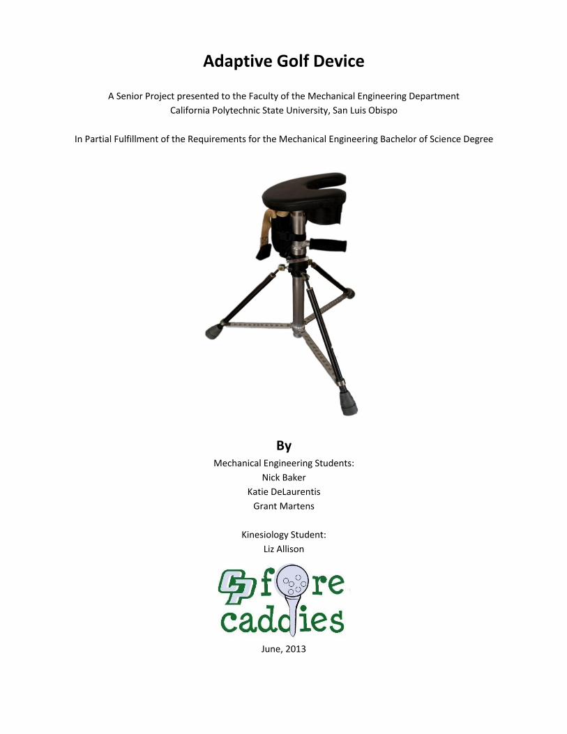
Adaptive Golf Device A Senior Project presented to the Faculty of the Mechanical Engineering Department California Polytechnic State University, San Luis Obispo In Partial Fulfillment of the Requirements for the Mechanical Engineering Bachelor of Science Degree By Mechanical Engineering Students: Nick Baker Katie DeLaurentis Grant Martens Kinesiology Student: Liz Allison June, 2013
Transcript of Adaptive Golf Device
Adaptive Golf Device
A Senior Project presented to the Faculty of the Mechanical Engineering Department
California Polytechnic State University, San Luis Obispo
In Partial Fulfillment of the Requirements for the Mechanical Engineering Bachelor of Science Degree
By Mechanical Engineering Students:
Nick Baker
Katie DeLaurentis
Grant Martens
Kinesiology Student:
Liz Allison
June, 2013
1
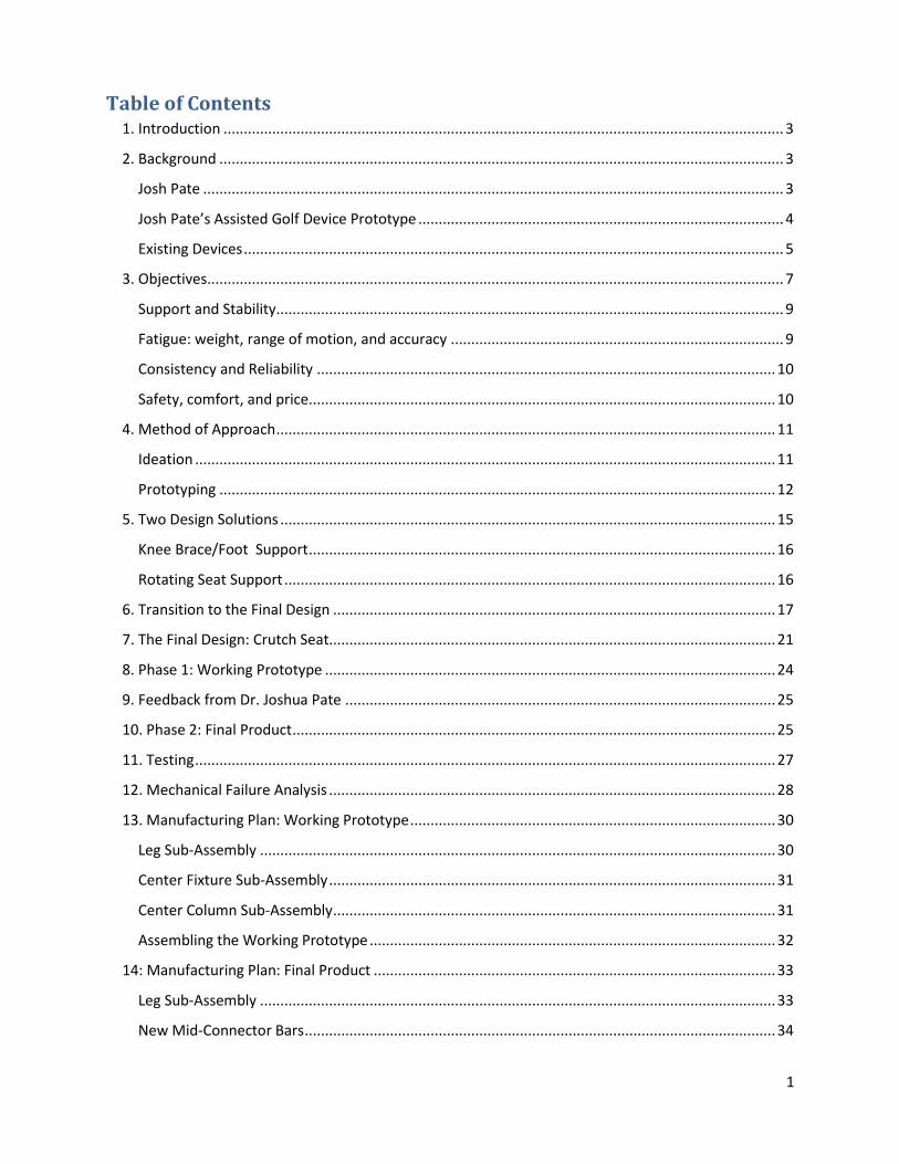
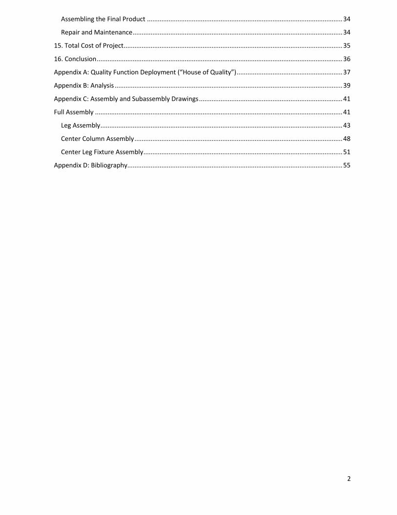
Table of Contents
1. Introduction .......................................................................................................................................... 3
2. Background ........................................................................................................................................... 3
Josh Pate ............................................................................................................................................... 3
Josh Pate’s Assisted Golf Device Prototype .......................................................................................... 4
Existing Devices ..................................................................................................................................... 5
3. Objectives .............................................................................................................................................. 7
Support and Stability ............................................................................................................................. 9
Fatigue: weight, range of motion, and accuracy .................................................................................. 9
Consistency and Reliability ................................................................................................................. 10
Safety, comfort, and price................................................................................................................... 10
4. Method of Approach ........................................................................................................................... 11
Ideation ............................................................................................................................................... 11
Prototyping ......................................................................................................................................... 12
5. Two Design Solutions .......................................................................................................................... 15
Knee Brace/Foot Support ................................................................................................................... 16
Rotating Seat Support ......................................................................................................................... 16
6. Transition to the Final Design ............................................................................................................. 17
7. The Final Design: Crutch Seat.............................................................................................................. 21
8. Phase 1: Working Prototype ............................................................................................................... 24
9. Feedback from Dr. Joshua Pate .......................................................................................................... 25
10. Phase 2: Final Product ....................................................................................................................... 25
11. Testing ............................................................................................................................................... 27
12. Mechanical Failure Analysis .............................................................................................................. 28
13. Manufacturing Plan: Working Prototype .......................................................................................... 30
Leg Sub-Assembly ............................................................................................................................... 30
Center Fixture Sub-Assembly .............................................................................................................. 31
Center Column Sub-Assembly ............................................................................................................. 31
Assembling the Working Prototype .................................................................................................... 32
14: Manufacturing Plan: Final Product ................................................................................................... 33
Leg Sub-Assembly ............................................................................................................................... 33
New Mid-Connector Bars .................................................................................................................... 34
2
Assembling the Final Product ............................................................................................................. 34
Repair and Maintenance ..................................................................................................................... 34
15. Total Cost of Project .......................................................................................................................... 35
16. Conclusion ......................................................................................................................................... 36
Appendix A: Quality Function Deployment (“House of Quality”) ........................................................... 37
Appendix B: Analysis ............................................................................................................................... 39
Appendix C: Assembly and Subassembly Drawings ................................................................................ 41
Full Assembly .......................................................................................................................................... 41
Leg Assembly ....................................................................................................................................... 43
Center Column Assembly .................................................................................................................... 48
Center Leg Fixture Assembly ............................................................................................................... 51
Appendix D: Bibliography........................................................................................................................ 55

3
1. Introduction
Our primary objective was to design a golf device that enables its user, who has limited leg movement
and control, to be able to produce a balanced golf swing. Ultimately, the device maximizes the golfer's
independence, and increases the accuracy of and power behind each shot. Specifically, the device was
designed around the needs and requirements of Dr. Joshua Pate, Professor of Adapted Recreation at
James Madison University. Dr. Pate has cerebral palsy limiting his lower body mobility and making it
difficult for him to produce a balanced golf swing.
This project was funded through a generous grant from the National Science Foundation’s Research to
Aid People with Disabilities (RAPD) Program. The RAPD program supports the development of device
and software technologies for persons with disabilities. California Polytechnic State University
supported this effort through the Mechanical Engineering and the Kinesiology Departments and our
team was composed of three mechanical engineering students, Grant Martens, Nick Baker, and Katie
DeLaurentis, and a kinesiology student, Liz Allison. Mechanical Engineering Professor Sarah Harding was
our senior project faculty advisor, and Dr. Kevin Taylor, Chair of the Kinesiology Department, was
instrumental in obtaining the funding and offering guidance. Our team was also in contact with Tony
Bennett, Director of Education for the Professional Golf Association (PGA) of Europe. Mr. Bennett was
uniquely qualified to contribute to this project because of his knowledge of the game and his experience
working with golfers who have disabilities.
This report focuses on how the final design meets these criteria. Also included are the specifics of the
process used to develop our final design, including analysis, manufacturing, making a working prototype,
and feedback from this prototype.
2. Background
As background for this project, our team has been able to interview and draw on the experiences of Dr.
Pate as well as review existing products to develop preliminary specifications.
Josh Pate
Josh Pate started golfing in 8th grade, and immediately developed a method of swinging with his left
hand while using a crutch in his right to stabilize himself. Throughout high school Dr. Pate used this
technique to compete, but stopped playing because of the fatigue associated with a round of golf.
Recently he has resumed playing the sport, shooting around 10-12 shots on par 5 holes, and 4-5 shots
on par 3 holes. This tendency to exceed par by a greater percentage on longer holes illustrates his
concern about distance; hitting the ball further and with more accuracy would result in fewer swings
each round, thus decreasing his fatigue while out on the course.
4
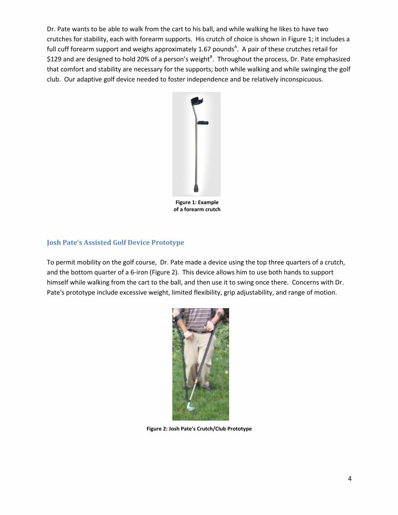
Dr. Pate wants to be able to walk from the cart to his ball, and while walking he likes to have two
crutches for stability, each with forearm supports. His crutch of choice is shown in Figure 1; it includes a
full cuff forearm support and weighs approximately 1.67 poundsA. A pair of these crutches retail for
$129 and are designed to hold 20% of a person’s weightB. Throughout the process, Dr. Pate emphasized
that comfort and stability are necessary for the supports; both while walking and while swinging the golf
club. Our adaptive golf device needed to foster independence and be relatively inconspicuous.
Josh Pate’s Assisted Golf Device Prototype
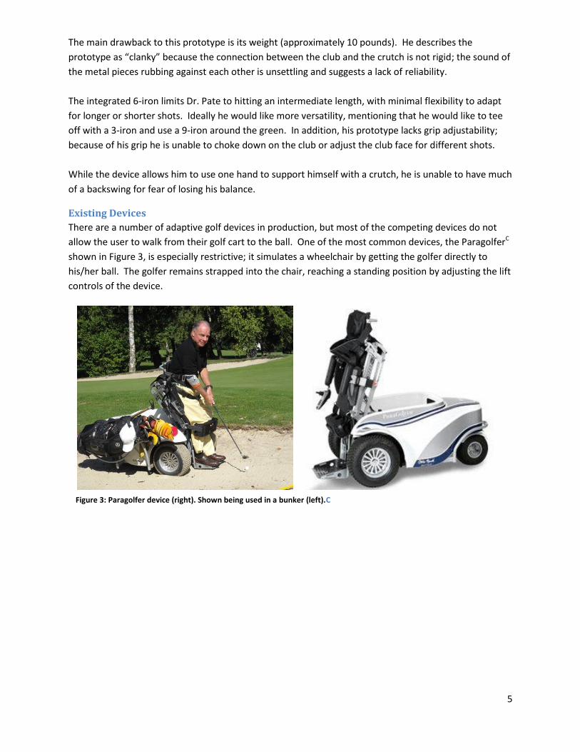
To permit mobility on the golf course, Dr. Pate made a device using the top three quarters of a crutch,
and the bottom quarter of a 6-iron (Figure 2). This device allows him to use both hands to support
himself while walking from the cart to the ball, and then use it to swing once there. Concerns with Dr.
Pate's prototype include excessive weight, limited flexibility, grip adjustability, and range of motion.
Figure 2: Josh Pate's Crutch/Club Prototype
Figure 1: Example of a forearm crutch
5
The main drawback to this prototype is its weight (approximately 10 pounds). He describes the
prototype as “clanky” because the connection between the club and the crutch is not rigid; the sound of
the metal pieces rubbing against each other is unsettling and suggests a lack of reliability.
The integrated 6-iron limits Dr. Pate to hitting an intermediate length, with minimal flexibility to adapt
for longer or shorter shots. Ideally he would like more versatility, mentioning that he would like to tee
off with a 3-iron and use a 9-iron around the green. In addition, his prototype lacks grip adjustability;
because of his grip he is unable to choke down on the club or adjust the club face for different shots.
While the device allows him to use one hand to support himself with a crutch, he is unable to have much
of a backswing for fear of losing his balance.
Existing Devices
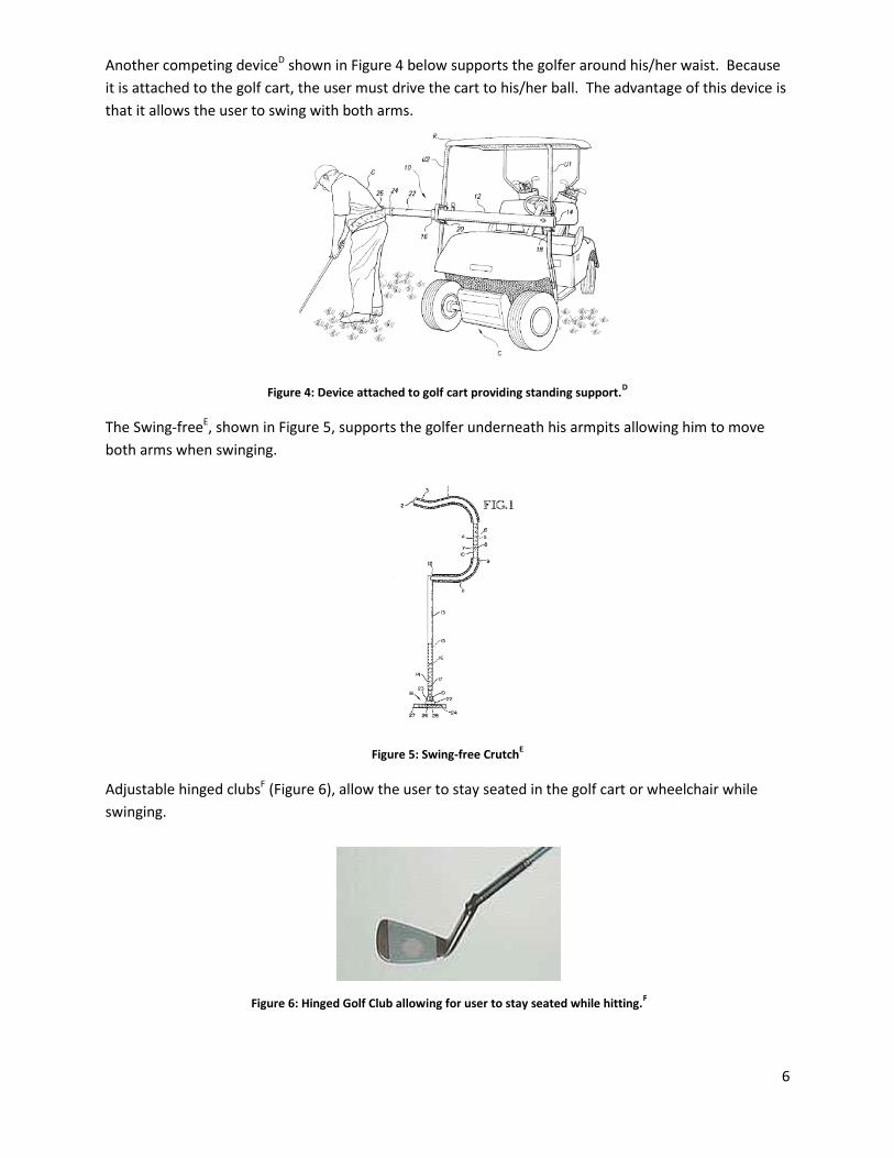
There are a number of adaptive golf devices in production, but most of the competing devices do not
allow the user to walk from their golf cart to the ball. One of the most common devices, the ParagolferC
shown in Figure 3, is especially restrictive; it simulates a wheelchair by getting the golfer directly to
his/her ball. The golfer remains strapped into the chair, reaching a standing position by adjusting the lift
controls of the device.
Figure 3: Paragolfer device (right). Shown being used in a bunker (left).C
6
Another competing deviceD shown in Figure 4 below supports the golfer around his/her waist. Because
it is attached to the golf cart, the user must drive the cart to his/her ball. The advantage of this device is
that it allows the user to swing with both arms.
Figure 4: Device attached to golf cart providing standing support.D
The Swing-freeE, shown in Figure 5, supports the golfer underneath his armpits allowing him to move
both arms when swinging.
Figure 5: Swing-free CrutchE
Adjustable hinged clubsF (Figure 6), allow the user to stay seated in the golf cart or wheelchair while
swinging.
Figure 6: Hinged Golf Club allowing for user to stay seated while hitting.F
7
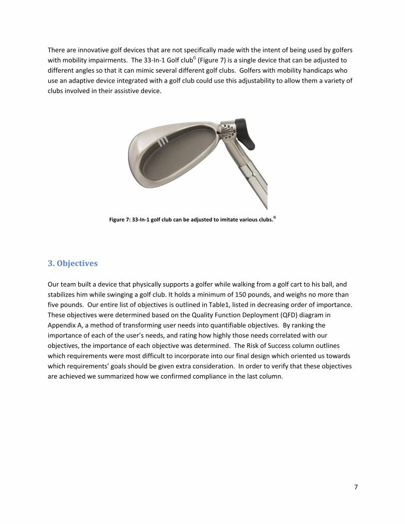
There are innovative golf devices that are not specifically made with the intent of being used by golfers
with mobility impairments. The 33-In-1 Golf clubG (Figure 7) is a single device that can be adjusted to
different angles so that it can mimic several different golf clubs. Golfers with mobility handicaps who
use an adaptive device integrated with a golf club could use this adjustability to allow them a variety of
clubs involved in their assistive device.
3. Objectives
Our team built a device that physically supports a golfer while walking from a golf cart to his ball, and
stabilizes him while swinging a golf club. It holds a minimum of 150 pounds, and weighs no more than
five pounds. Our entire list of objectives is outlined in Table1, listed in decreasing order of importance.
These objectives were determined based on the Quality Function Deployment (QFD) diagram in
Appendix A, a method of transforming user needs into quantifiable objectives. By ranking the
importance of each of the user’s needs, and rating how highly those needs correlated with our
objectives, the importance of each objective was determined. The Risk of Success column outlines
which requirements were most difficult to incorporate into our final design which oriented us towards
which requirements’ goals should be given extra consideration. In order to verify that these objectives
are achieved we summarized how we confirmed compliance in the last column.
Figure 7: 33-In-1 golf club can be adjusted to imitate various clubs.G
8
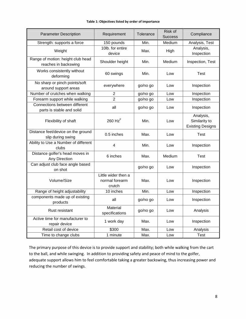
Table 1: Objectives listed by order of importance
Parameter Description Requirement Tolerance Risk of
Success Compliance
Strength: supports a force 150 pounds Min. Medium Analysis, Test
Weight 10lb. for entire
device Max. High
Analysis,
Inspection
Range of motion: height club head
reaches in backswing Shoulder height Min. Medium Inspection, Test
Works consistently without
deforming 60 swings Min. Low Test
No sharp or pinch points/soft
around support areas everywhere go/no go Low Inspection
Number of crutches when walking 2 go/no go Low Inspection
Forearm support while walking 2 go/no go Low Inspection
Connections between different
parts is stable and solid all go/no go Low Inspection
Flexibility of shaft 260 HzF
Min. Low
Analysis,
Similarity to
Existing Designs
Distance feet/device on the ground
slip during swing 0.5 inches Max. Low Test
Ability to Use a Number of different
clubs 4 Min. Low Inspection
Distance golfer's head moves in
Any Direction 6 inches Max. Medium Test
Can adjust club face angle based
on shot go/no go Low Inspection
Volume/Size
Little wider then a
normal forearm
crutch
Max. Low Inspection
Range of height adjustability 10 inches Min. Low Inspection
components made up of existing
products all go/no go Low Inspection
Rust resistant Material
specifications go/no go Low Analysis
Active time for manufacturer to
repair device 1 work day Max. Low Inspection
Retail cost of device $300 Max. Low Analysis
Time to change clubs 1 minute Max. Low Test
The primary purpose of this device is to provide support and stability; both while walking from the cart
to the ball, and while swinging. In addition to providing safety and peace of mind to the golfer,
adequate support allows him to feel comfortable taking a greater backswing, thus increasing power and
reducing the number of swings.
9
Support and Stability
Our objective was to make a device that will not yield when 200 pounds is applied to it and can support
20% of a person's weight while walking. Based on Dr. Pate's requirements, our design needed to
support both sides of his body for weight distribution and provide forearm support.
To measure the device's ability to stabilize the golfer when swinging, our team looked at how a golfer
moves throughout the swing. For example, a golfer's feet slipping more than half an inch during a swing
might cause him/her to lose balance. Similarly, stability of the upper body can be measured by looking
at head movement; ideally, his/her head would move no more than 6 inches, a reasonable amount for a
balanced golf swing.
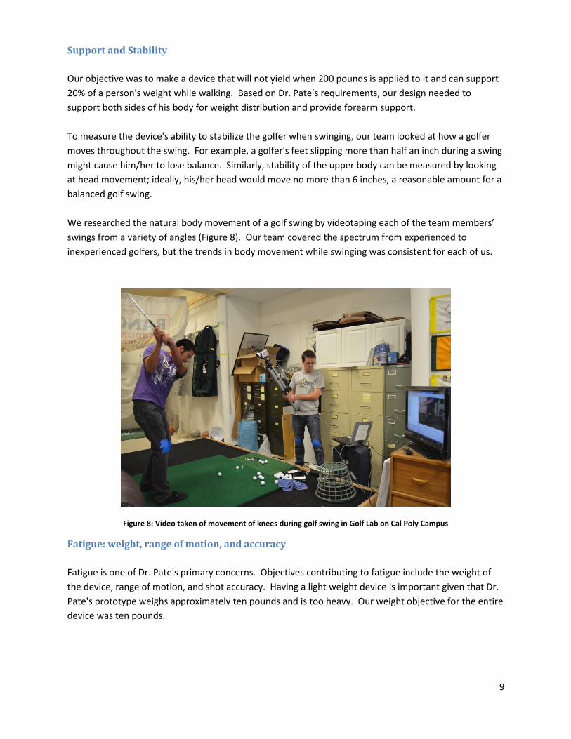
We researched the natural body movement of a golf swing by videotaping each of the team members’
swings from a variety of angles (Figure 8). Our team covered the spectrum from experienced to
inexperienced golfers, but the trends in body movement while swinging was consistent for each of us.
Figure 8: Video taken of movement of knees during golf swing in Golf Lab on Cal Poly Campus
Fatigue: weight, range of motion, and accuracy
Fatigue is one of Dr. Pate's primary concerns. Objectives contributing to fatigue include the weight of
the device, range of motion, and shot accuracy. Having a light weight device is important given that Dr.
Pate's prototype weighs approximately ten pounds and is too heavy. Our weight objective for the entire
device was ten pounds.
10
Fatigue would also be greatly decreased if the golfer swings fewer times in a round. There is a direct
correlation between range of motion and how far the golfer hits the ball; our objective is to enable the
golfer to bring the club head up to at least shoulder height in his/her back swing. This is not a full swing,
but it doubles the range of motion in Dr. Pate’s current technique.
Increasing accuracy reduces the number of swings. Our device facilitates accuracy by being versatile. If
the golfer has an option of using a range of different clubs, he/she can pick the club best suited to each
shot. Dr. Pate mentioned that he would like to be able to use the range of clubs from 3-iron to 9-iron,
thus incorporating the versatility of at least four clubs (3-iron, 5-iron, 7-iron, 9-iron) fulfills this objective.
The golfer also obtains accuracy by having control over how he grips the club, choking down on it or
changing club head angle based on his prospective shot. For example, this gives the golfer the ability to
open the club face when hitting out of bunkers.
Consistency and Reliability
It was important to test the consistency and reliability of the device because it should work 100 percent
of the time and last for years. To ensure it works consistently, all parts needed to be connected to each
other rigidly. We also wanted to confirm that it could withstand an average round of golf, or 60 full
swings. Considering inclement weather conditions, all parts needed to be manufactured from rust
resistant materials.
Safety, comfort, and price
In addition to providing adequate support, the device needed to be free of any sharp or pinch points,
guaranteeing safety. To increase the comfort of the golfer, all support areas needed to be soft. The
device also needed to be adjustable for people of different heights. Based on the common range of
heights, our team determined that it should be adjustable to a range of at least ten inches.
On the business side, our goal was that the retail cost of the device should be no more than $300; this
was in line with the price range of other golf and crutch devices on the market. To make the device
easier to manufacture, many of its components are commercial, off-the-shelf parts.
In summary, based on our customers’ requirements we developed a variety of objective specifications
that the device meets, paying particular attention to the weight of the device, the strength it can
withstand, and the range of motion it allows.
11
4. Method of Approach
We approached this problem by initially performing background research on the type of devices and
equipment on the market. Our research was geared toward learning about the various types of
crutches currently available, golf equipment presently in existence, and other various golf devices that
are aimed at aiding a person with a disability. After this initial research, we refined our questions to
efficiently communicate with Josh Pate at a status meeting. This information was then used to hone our
requirements. A Quality Function Deployment (QFD) diagram was created to translate the client’s needs
into quantifiable engineering specifications (See Appendix A). This provided an outline to test our
designs and establish parameters to ensure that we were solving the intended problem. After the QFD
was created, we presented a project proposal to determine if the problem was accurately addressed. If
another iteration was required, we would have conducted more research and possibly re-interviewed
the sponsor and client resulting in forming another QFD and another design presentation. This iterative
process continued until the specifications were correctly addressed.
Ideation
Once we had a complete understanding of the problem, we began generating concepts. In order to
generate concepts, a variety of brainstorming methods were used including the 6-3-5 method, the menu
matrix and the SCAMPER method.
The 6-3-5 method has each group member independently draw three sketches of possible ideas within a
five minute period. The reason for this independent effort is to eliminate the blocking or criticism of
one’s ideas and fostering an environment of creative freedom.
The menu matrix method has members create a suite of attribute columns with alternative solutions
listed underneath each attribute. Once all ideas are generated, the team randomly connects a word
from every column to create an idea.
The SCAMPER method is used to highlight alternative solutions. SCAMPER is an acronym standing for
Substitute, Combine, Adapt, Modify, Put to other uses, Eliminate, Rearrange/Reverse. The team then
proceeds to create an answer for every category. After ideas are brainstormed and possible concepts
generated, these concepts are then evaluated. In order to evaluate all design concepts, a quick mock-up
prototype is built and tested. If building a quick mock-up is not possible then data is gathered on the
design components first and a decision on the design is made from this accumulated information.
In a brainstorming session in which we incorporated the above listed idea generation methods, we were
able to create a multitude of possible ideas using the 6-3-5 method. After brainstorming for fifteen
minutes we then shared our ideas with each other and taped sketches to the wall for everyone to see.
We iterated this process, using each other’s ideas as a springboard for new ones.
12
Using these ideas as a basis, we were then able to set up a menu matrix to help us create more ideas.
The categories we used for our menu matrix were “ways to hit the ball”, “various locations that could be
used to support the person”, “different devices that could be used to support the person”, “how to
incorporate a variety of clubs”, and lastly “modes of transportation from golf cart to ball.” As a team
we then performed the SCAMPER method where we eliminated ways of doing things under each
category until we had narrowed it down to the few methods of accomplishing each category that we
thought worked the best. From these new refined categories, we then proceeded to connect words
from each category which provided us with a plethora of ideas.
Prototyping
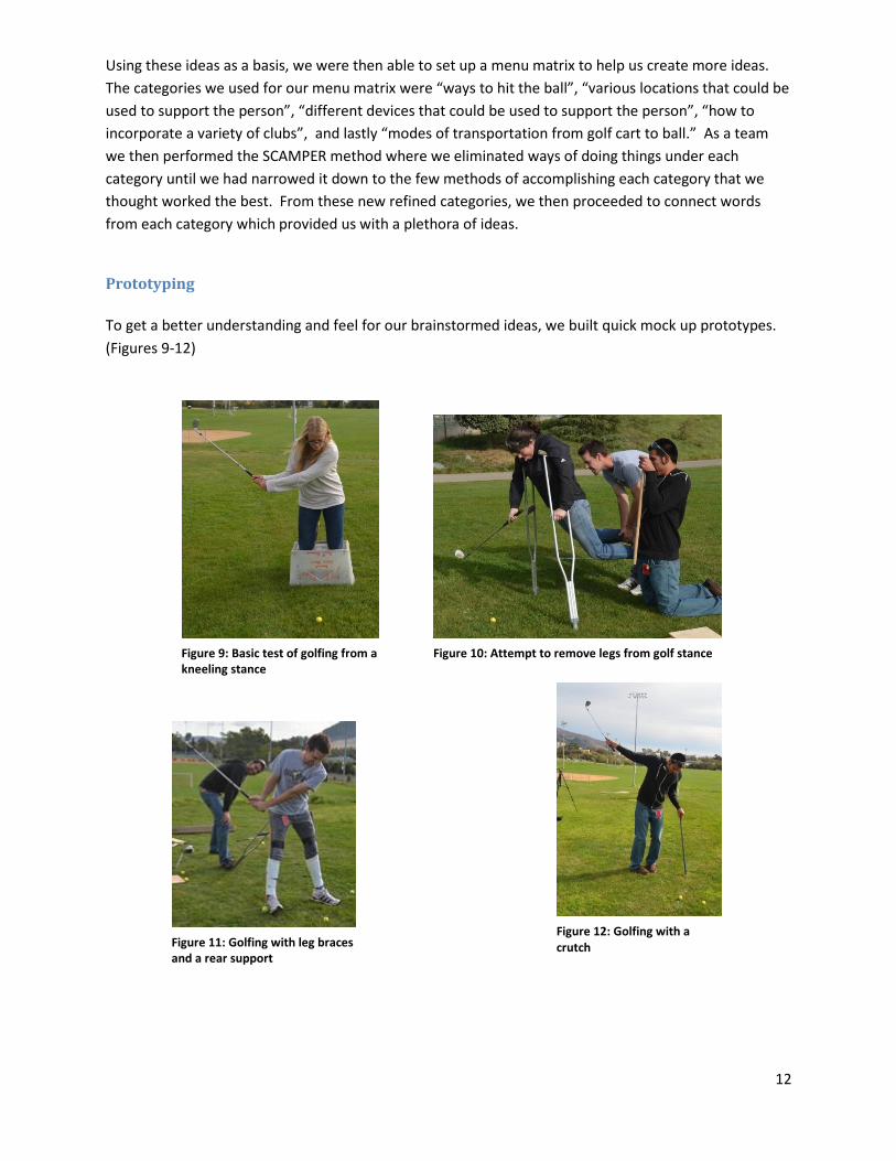
To get a better understanding and feel for our brainstormed ideas, we built quick mock up prototypes.
(Figures 9-12)
Figure 9: Basic test of golfing from a kneeling stance
Figure 10: Attempt to remove legs from golf stance
Figure 11: Golfing with leg braces and a rear support
Figure 12: Golfing with a crutch
13
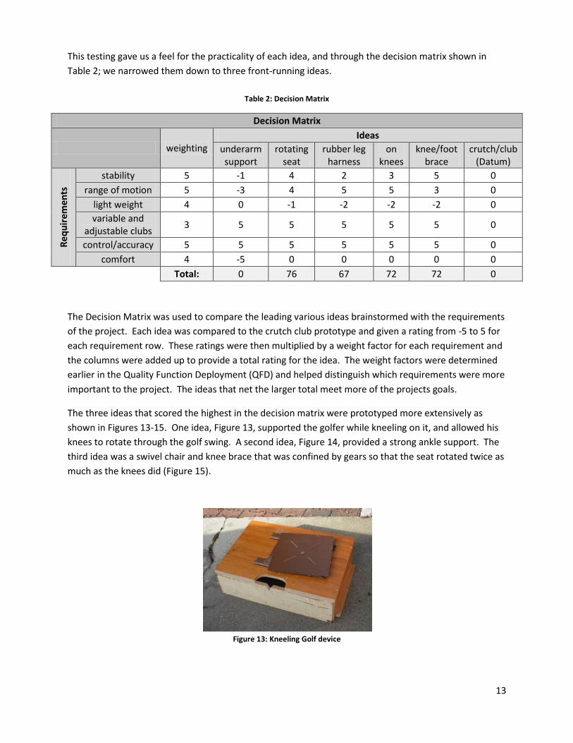
This testing gave us a feel for the practicality of each idea, and through the decision matrix shown in
Table 2; we narrowed them down to three front-running ideas.
Table 2: Decision Matrix
Decision Matrix
weighting Ideas
underarm support
rotating seat
rubber leg harness
on knees
knee/foot brace
crutch/club (Datum)
Re
qu
irem
en
ts
stability 5 -1 4 2 3 5 0
range of motion 5 -3 4 5 5 3 0
light weight 4 0 -1 -2 -2 -2 0
variable and adjustable clubs
3 5 5 5 5 5 0
control/accuracy 5 5 5 5 5 5 0
comfort 4 -5 0 0 0 0 0
Total: 0 76 67 72 72 0
The Decision Matrix was used to compare the leading various ideas brainstormed with the requirements
of the project. Each idea was compared to the crutch club prototype and given a rating from -5 to 5 for
each requirement row. These ratings were then multiplied by a weight factor for each requirement and
the columns were added up to provide a total rating for the idea. The weight factors were determined
earlier in the Quality Function Deployment (QFD) and helped distinguish which requirements were more
important to the project. The ideas that net the larger total meet more of the projects goals.
The three ideas that scored the highest in the decision matrix were prototyped more extensively as
shown in Figures 13-15. One idea, Figure 13, supported the golfer while kneeling on it, and allowed his
knees to rotate through the golf swing. A second idea, Figure 14, provided a strong ankle support. The
third idea was a swivel chair and knee brace that was confined by gears so that the seat rotated twice as
much as the knees did (Figure 15).
Figure 13: Kneeling Golf device

14
Figure 14: Knee/Foot Brace Support
After building the prototypes, it became apparent that the kneeling idea was not going to work because
it felt uncomfortable and adequate balance could not be provided. We also determined that the knee
support was not necessary for the swivel chair idea. To compare these three ideas we refined our
decision matrix as shown in Table 3.
Figure 15: Rotating Seat Prototype

15
Table 3: Refined Decision Matrix
Refined Decision Matrix
weighting Ideas
rotating seat on knees knee/foot brace crutch/club (datum)
Re
qu
irem
en
ts
stability (while swinging) 5 4 1 5 0
stability (from cart to ball) 5 0 -1 0 0
range of motion 5 5 5 4 0
light weight 4 -1 -2 -2 0
variable and adjustable clubs 3 5 5 5 0
control/accuracy 5 5 2 5 0
Comfort 4 0 -1 0 0
not bulky 4 -1 -2 -2 0
manufacturability 3 0 0 0 0
Safety 5 5 5 5 0
relatively inconspicuous 3 -2 -3 -1 0
Total: 96 46 91 0
The previous decision matrix determined that the best solutions for the project were either a rotating
seat, on knees device or knee/foot brace. After many prototyping sessions, a new decision matrix was
made, which consisted of a few added requirements and the ratings were again done on a scale from -5
to 5, with the information gained from the testing. This resulted in some requirement ratings being
changed and adjusted. Again, all requirement ratings were multiplied by the corresponding weight
factor in their row and then all of these values in the column were summed resulting in the total rating
of the idea. The refined decision matrix clearly showed that there are two leading solutions for the
project, which are the rotating seat concept and the knee/foot brace idea.
5. Two Design Solutions
After brainstorming, prototyping, and testing a myriad of ideas, we narrowed our possible solutions to
two ideas. Both ideas are centered on enabling the user to stand while providing balance assistance and
allowing the use of both arms in the performance of the golf swing. The two concepts explained below
are titled “Knee Brace/Foot Support”, and “Rotating Seat Support”. Ultimately, the rotating seat
support led to the final crutch seat design which is discussed in Section 7.
16
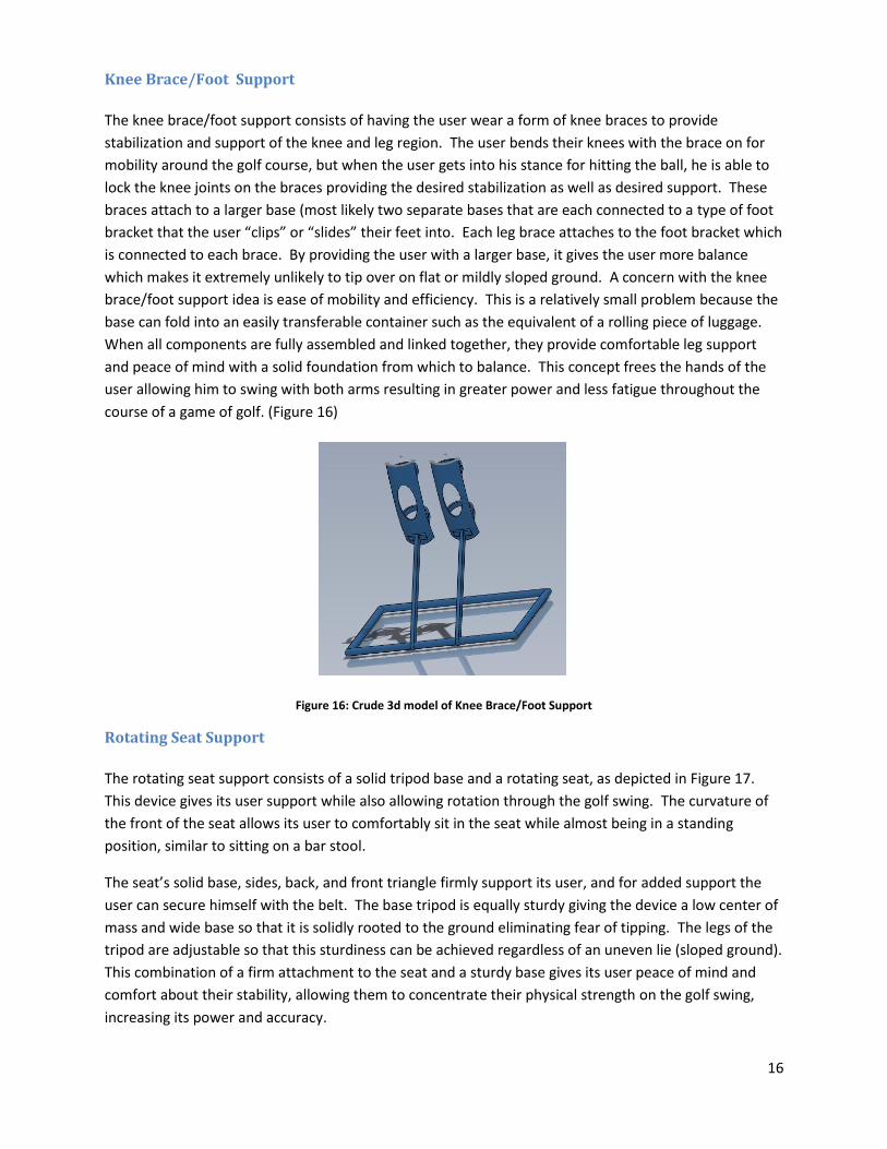
Knee Brace/Foot Support
The knee brace/foot support consists of having the user wear a form of knee braces to provide
stabilization and support of the knee and leg region. The user bends their knees with the brace on for
mobility around the golf course, but when the user gets into his stance for hitting the ball, he is able to
lock the knee joints on the braces providing the desired stabilization as well as desired support. These
braces attach to a larger base (most likely two separate bases that are each connected to a type of foot
bracket that the user “clips” or “slides” their feet into. Each leg brace attaches to the foot bracket which
is connected to each brace. By providing the user with a larger base, it gives the user more balance
which makes it extremely unlikely to tip over on flat or mildly sloped ground. A concern with the knee
brace/foot support idea is ease of mobility and efficiency. This is a relatively small problem because the
base can fold into an easily transferable container such as the equivalent of a rolling piece of luggage.
When all components are fully assembled and linked together, they provide comfortable leg support
and peace of mind with a solid foundation from which to balance. This concept frees the hands of the
user allowing him to swing with both arms resulting in greater power and less fatigue throughout the
course of a game of golf. (Figure 16)
Figure 16: Crude 3d model of Knee Brace/Foot Support
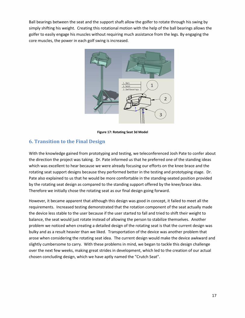
Rotating Seat Support
The rotating seat support consists of a solid tripod base and a rotating seat, as depicted in Figure 17.
This device gives its user support while also allowing rotation through the golf swing. The curvature of
the front of the seat allows its user to comfortably sit in the seat while almost being in a standing
position, similar to sitting on a bar stool.
The seat’s solid base, sides, back, and front triangle firmly support its user, and for added support the
user can secure himself with the belt. The base tripod is equally sturdy giving the device a low center of
mass and wide base so that it is solidly rooted to the ground eliminating fear of tipping. The legs of the
tripod are adjustable so that this sturdiness can be achieved regardless of an uneven lie (sloped ground).
This combination of a firm attachment to the seat and a sturdy base gives its user peace of mind and
comfort about their stability, allowing them to concentrate their physical strength on the golf swing,
increasing its power and accuracy.
17
Ball bearings between the seat and the support shaft allow the golfer to rotate through his swing by
simply shifting his weight. Creating this rotational motion with the help of the ball bearings allows the
golfer to easily engage his muscles without requiring much assistance from the legs. By engaging the
core muscles, the power in each golf swing is increased.
Figure 17: Rotating Seat 3d Model
6. Transition to the Final Design With the knowledge gained from prototyping and testing, we teleconferenced Josh Pate to confer about
the direction the project was taking. Dr. Pate informed us that he preferred one of the standing ideas
which was excellent to hear because we were already focusing our efforts on the knee brace and the
rotating seat support designs because they performed better in the testing and prototyping stage. Dr.
Pate also explained to us that he would be more comfortable in the standing-seated position provided
by the rotating seat design as compared to the standing support offered by the knee/brace idea.
Therefore we initially chose the rotating seat as our final design going forward.
However, it became apparent that although this design was good in concept, it failed to meet all the
requirements. Increased testing demonstrated that the rotation component of the seat actually made
the device less stable to the user because if the user started to fall and tried to shift their weight to
balance, the seat would just rotate instead of allowing the person to stabilize themselves. Another
problem we noticed when creating a detailed design of the rotating seat is that the current design was
bulky and as a result heavier than we liked. Transportation of the device was another problem that
arose when considering the rotating seat idea. The current design would make the device awkward and
slightly cumbersome to carry. With these problems in mind, we began to tackle this design challenge
over the next few weeks, making great strides in development, which led to the creation of our actual
chosen concluding design, which we have aptly named the "Crutch Seat".
18
Before the "Crutch Seat" is explained in great detail, it is necessary to outline the brainstorming and
development that occurred over the first couple of weeks of winter quarter leading to the final design in
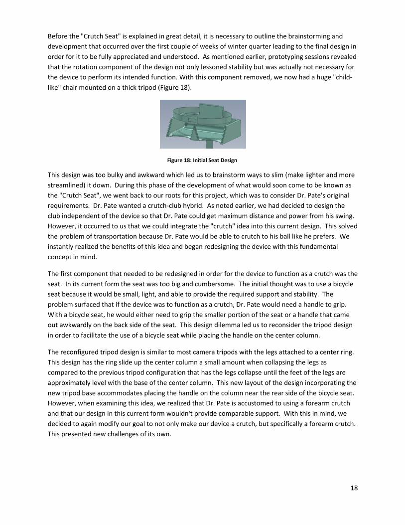
order for it to be fully appreciated and understood. As mentioned earlier, prototyping sessions revealed
that the rotation component of the design not only lessoned stability but was actually not necessary for
the device to perform its intended function. With this component removed, we now had a huge "child-
like" chair mounted on a thick tripod (Figure 18).
Figure 18: Initial Seat Design
This design was too bulky and awkward which led us to brainstorm ways to slim (make lighter and more
streamlined) it down. During this phase of the development of what would soon come to be known as
the "Crutch Seat", we went back to our roots for this project, which was to consider Dr. Pate's original
requirements. Dr. Pate wanted a crutch-club hybrid. As noted earlier, we had decided to design the
club independent of the device so that Dr. Pate could get maximum distance and power from his swing.
However, it occurred to us that we could integrate the "crutch" idea into this current design. This solved
the problem of transportation because Dr. Pate would be able to crutch to his ball like he prefers. We
instantly realized the benefits of this idea and began redesigning the device with this fundamental
concept in mind.
The first component that needed to be redesigned in order for the device to function as a crutch was the
seat. In its current form the seat was too big and cumbersome. The initial thought was to use a bicycle
seat because it would be small, light, and able to provide the required support and stability. The
problem surfaced that if the device was to function as a crutch, Dr. Pate would need a handle to grip.
With a bicycle seat, he would either need to grip the smaller portion of the seat or a handle that came
out awkwardly on the back side of the seat. This design dilemma led us to reconsider the tripod design
in order to facilitate the use of a bicycle seat while placing the handle on the center column.
The reconfigured tripod design is similar to most camera tripods with the legs attached to a center ring.
This design has the ring slide up the center column a small amount when collapsing the legs as
compared to the previous tripod configuration that has the legs collapse until the feet of the legs are
approximately level with the base of the center column. This new layout of the design incorporating the
new tripod base accommodates placing the handle on the column near the rear side of the bicycle seat.
However, when examining this idea, we realized that Dr. Pate is accustomed to using a forearm crutch
and that our design in this current form wouldn't provide comparable support. With this in mind, we
decided to again modify our goal to not only make our device a crutch, but specifically a forearm crutch.
This presented new challenges of its own.

19
Making the switch from "crutch" to" forearm crutch" design provided us with two choices. We
determined that the previously selected tripod continued to meet the requirements of the design and
could be retained. Therefore the reconfigurations would need to be to the seat and upper center
column in order to make the device both a sitting-standing support and a forearm crutch when
collapsed. One choice was to preserve the bicycle seat, and attach a forearm cuff to the back of the seat
with a handle attached to the center column. The second choice was to design a new seat with a hole in
its center large enough for an arm to go through and grip a handle. The forearm cuff would be on a pole
that attached to the seat and could swing down when using the device as a golfing support and swing up
when using the device as a crutch. The first choice seemed uncomfortable to walk with and overall, we
believed it wasn't the best solution to the problem. Therefore we chose to proceed forward with option
two.
This new redesign incorporated a tripod base connected to a center column consisting of a seat and a
handle. The seat was designed to have a hole in its center large enough for a hand to go through, so that
the user can grab the handle located just below the seat. Attached to the seat would be a pole with the
forearm cuff on a swivel enabling it to swivel up when the device is in "crutch" form and swivel down
and out of the way when using it as a golf support device. When presenting this new design to our
faculty advisor Professor Sarah Harding, we mentioned our reservations about the swivel cuff. She
agreed and we immediately began bouncing ideas off of each other. One suggestion eventually stood
out among the rest; integrating the cuff part into the seat, in other words, to make the seat the forearm
cuff.
Figure 19: Final Seat Design

20
We immediately began a complete redesign creating a hybrid design of the seat and the support cuff.
The newly designed seat is horseshoe shaped allowing plenty of area to sit on when using the device for
support while golfing, and allows for the seat to also act as a forearm cuff when the device is collapsed
and performing as a crutch (Figure 19). The handle location remains on the center column and the
tripod was retained. Seat belts were added to the design for extra support and stability. Dimensions
were altered in order to accommodate for the newly designed seat and its multipurpose function. This
was our last major overhaul of the chosen design and at this point in its career it has been coined the
"Crutch Seat" (Figure 20).
Figure 20: Chosen Final Design
21
7. The Final Design: Crutch Seat
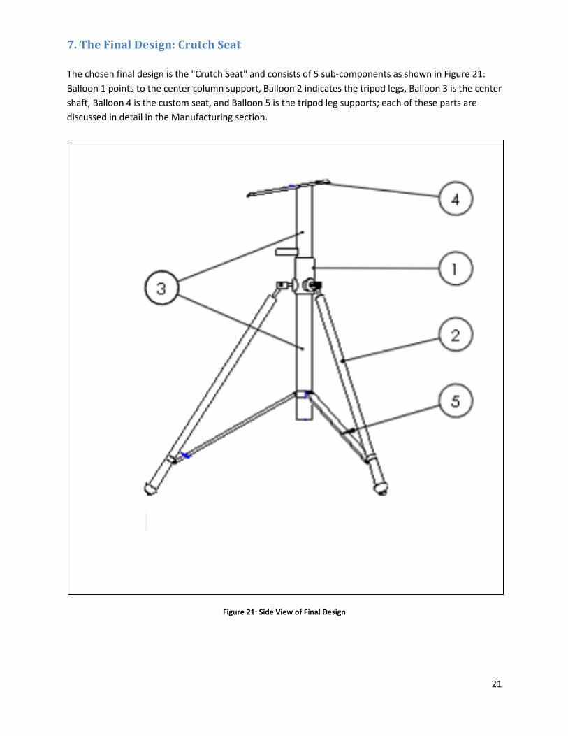
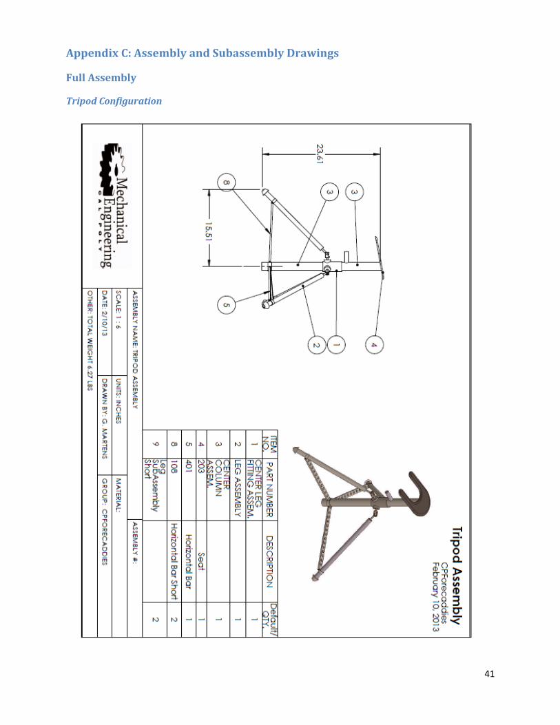
The chosen final design is the "Crutch Seat" and consists of 5 sub-components as shown in Figure 21:
Balloon 1 points to the center column support, Balloon 2 indicates the tripod legs, Balloon 3 is the center
shaft, Balloon 4 is the custom seat, and Balloon 5 is the tripod leg supports; each of these parts are
discussed in detail in the Manufacturing section.
Figure 21: Side View of Final Design
22
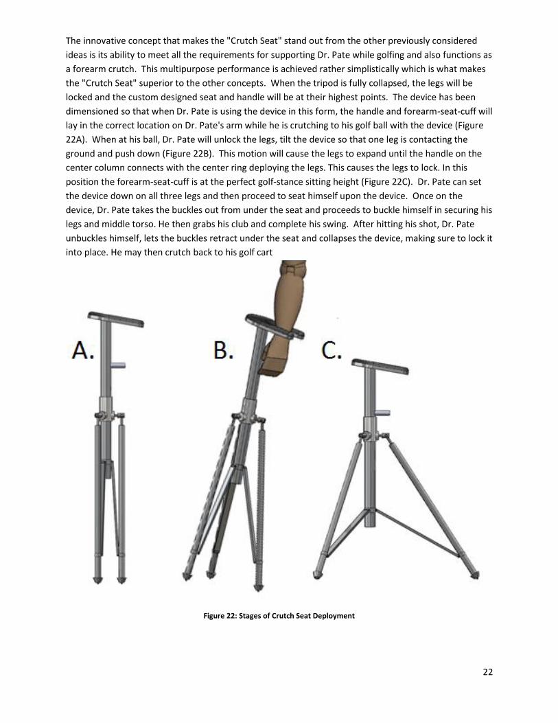
The innovative concept that makes the "Crutch Seat" stand out from the other previously considered
ideas is its ability to meet all the requirements for supporting Dr. Pate while golfing and also functions as
a forearm crutch. This multipurpose performance is achieved rather simplistically which is what makes
the "Crutch Seat" superior to the other concepts. When the tripod is fully collapsed, the legs will be
locked and the custom designed seat and handle will be at their highest points. The device has been
dimensioned so that when Dr. Pate is using the device in this form, the handle and forearm-seat-cuff will
lay in the correct location on Dr. Pate's arm while he is crutching to his golf ball with the device (Figure
22A). When at his ball, Dr. Pate will unlock the legs, tilt the device so that one leg is contacting the
ground and push down (Figure 22B). This motion will cause the legs to expand until the handle on the
center column connects with the center ring deploying the legs. This causes the legs to lock. In this
position the forearm-seat-cuff is at the perfect golf-stance sitting height (Figure 22C). Dr. Pate can set
the device down on all three legs and then proceed to seat himself upon the device. Once on the
device, Dr. Pate takes the buckles out from under the seat and proceeds to buckle himself in securing his
legs and middle torso. He then grabs his club and complete his swing. After hitting his shot, Dr. Pate
unbuckles himself, lets the buckles retract under the seat and collapses the device, making sure to lock it
into place. He may then crutch back to his golf cart
Figure 22: Stages of Crutch Seat Deployment

23
Ultimately this chosen final design is the perfect merging of engineering and ergonomics. A key
requirement of our project was to provide Dr. Pate with support and stability while golfing. This design
meets and exceeds this. When the device is deployed, it provides support through the seat support and
the supplied buckling system. Stability is added to the whole device through the tripod base which
eliminates the possibility of tipping for flat and small angled surfaces. The provided belts add stability by
allowing Dr. Pate to correct himself should he begin to fall by pushing his weight into the belts to shift
himself the other direction. The final design of the "Crutch Seat" also provides support and stability in
its collapsed form. This feature really makes it stand out from the other considered concepts. Support
is provided in the form of a forearm crutch. The seat provides support and stability to the forearm while
acting as a cuff and the whole device provides support and stability to Dr. Pate when he is using it as a
forearm crutch. An added benefit of making the device a forearm crutch, Dr. Pate is in his comfort zone
since a forearm crutch is his common mode of transportation.
Another requirement of the project was comfort. As noted earlier, it is comfortable to Dr. Pate in its
collapsed form because he is accustomed to using forearm crutches and therefore, our device is routine
for him. The device is comfortable to Dr. Pate in its expanded form as well. This is because the seat
support gives him the third point of support providing him with the three point stance he currently
achieves by using one of his crutches to provide a third point for added stability and support. The
"Crutch Seat" design provides this point which keeps Dr. Pate relatively in his comfort zone. Also, the
upholstered seat adds some extra comfort.
Another goal of this project was to make a design that was portable and lightweight. Lightweight is
defined as being approximately 5 pounds and able to be lifted with one arm. This requirement pertains
to the transportation of the device; therefore we only analyzed the design in its collapsed form when
determining if it meets this requirement. Since the entire idea was designed to be a crutch, the device is
by definition portable. By functioning as a crutch it allows Dr. Pate to transport it in an easy and
comfortable fashion, which also meets the lightweight requirement because he can lift it with one arm.
After designing the device in Solidworks, the weight was approximated to be just over 6 pounds, which
was close to the set goal of 5 pound.
Lastly, the "Crutch Seat" design meets the final requirement of providing increased power. When the
device is fully deployed and supporting Dr. Pate, he is able to swing a club with both hands allowing him
increased range of motion resulting in increased power and improved distance.
The "Crutch Seat" was built in two phases. Phase one consisted of building a working prototype. Phase
two began after Dr. Pate tested the device. Based on his input, we made necessary reconfigurations and
refinements.
24
8. Phase 1: Working Prototype
We decided to custom build the tripod using aluminum tubing because commercial, off-the-shelf tripods
could not support the required weight. Therefore, the legs were initially made with 3/8’’ thick aluminum
tubing. Since the legs were made out of aluminum instead of steel, the weight of the device could be
kept under 10 pounds.
For the prototype design, the seat was also custom made out of an aluminum base and upholstered for
comfort. The seat belt was attached to the underside of the seat to provide extra support when
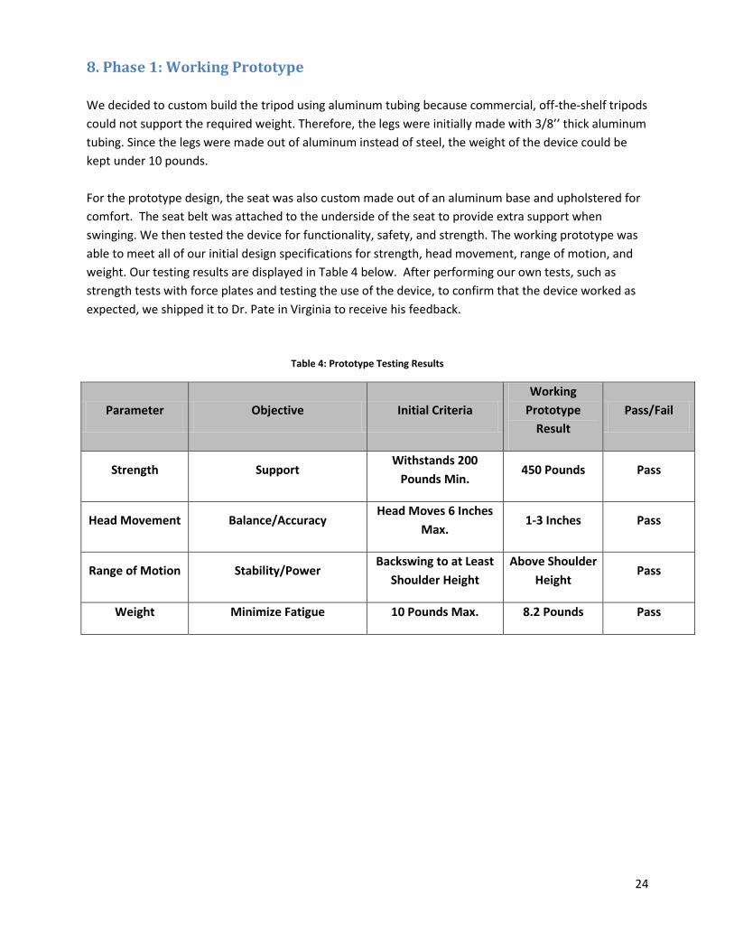
swinging. We then tested the device for functionality, safety, and strength. The working prototype was
able to meet all of our initial design specifications for strength, head movement, range of motion, and
weight. Our testing results are displayed in Table 4 below. After performing our own tests, such as
strength tests with force plates and testing the use of the device, to confirm that the device worked as
expected, we shipped it to Dr. Pate in Virginia to receive his feedback.
Table 4: Prototype Testing Results
Parameter Objective Initial Criteria
Working
Prototype
Result
Pass/Fail
Strength Support Withstands 200
Pounds Min. 450 Pounds Pass
Head Movement Balance/Accuracy Head Moves 6 Inches
Max. 1-3 Inches Pass
Range of Motion Stability/Power Backswing to at Least
Shoulder Height
Above Shoulder
Height Pass
Weight Minimize Fatigue 10 Pounds Max. 8.2 Pounds Pass

25
9. Feedback from Dr. Joshua Pate
Once the device was sent to Dr. Pate, we asked him to test it for functionality, ease of use, weight, and
comfort to make sure that our design met his specific needs. Dr. Pate’s feedback on our design was that
it was a little too heavy, too tall, and too difficult to walk around as a crutch because of the three equal
length legs. He suggested to make the device lighter, 6 inches shorter, and to make one of the legs
longer to make it easier to use as a crutch.
Therefore, for the final product, the legs were to be made out of carbon fiber to reduce the weight of
the device without compensating for the overall strength, and made shorter to fit Dr. Pate’s desired
height for the seat. One leg was also made longer to make it easier to use as a crutch.
10. Phase 2: Final Product The final product incorporates the changes requested by Dr. Pate after he tested the working prototype.
The center column assembly was retained from the working prototype because it was a great fit for Dr.
Pate. The major changes were to the legs. The legs were shortened and one of the three legs was cut to
about an inch longer than the others to facilitate using the device as a crutch. We recalculated the
geometry to provide for a longer leg when used as a crutch, but when the device is fully deployed, the
device lays flat.
In addition to making the legs shorter, carbon fiber was substituted for the aluminum to reduce the total
weight of the device.
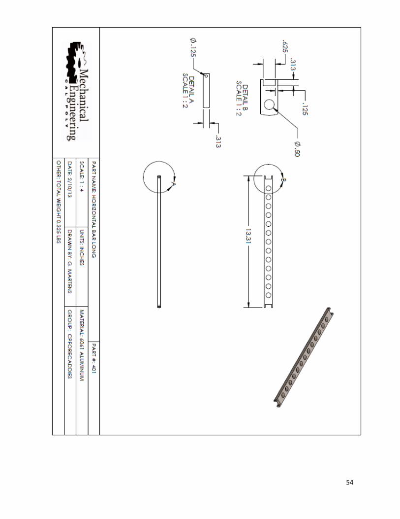
The shortening of the legs also required making new mid-connecting bars. These were made out of
aluminum like in the working prototype, but instead of cutting a slot in the center to reduce the weight,
1/2 inch holes were drilled. These holes reduced the weight of the bar while maintaining the bar's
strength.
In addition to carbon fiber legs and new mid-connecting bars, new crutch feet were added to the final
design. We purchased Tornado brand crutch feet based on Dr. Pate's advice and experience using
Tornado feet. These Tornado feet are gel filled providing shock absorption resulting in maximum
comfort and joint protection for the user.

26
The result is a final product device that weighs 7 pounds, which is 1.2 pounds lighter than its
predecessor, the working prototype. The total sitting height is dropped by 2 inches from the prototype.
(Figure 23)
Figure 23: Final Product

27
11. Testing We conducted initial testing on the working prototype to verify that the design achieved our objectives.
To ensure that the strength of the final design would be adequate, we determined the loading
conditions using the working prototype. To ensure the stability and range of motion of the design we
watched Dr. Pate swing while being supported by the device, and we weighed the device to confirm that
it was below the objective weight. The table below summarizes the results of our prototype testing.
Table 5: Final Product Testing Results
Parameter Objective Initial Criteria
Working
Prototype
Result
Criteria After
Dr. Pate’s
Feedback
Final
Product
Result
Pass/Fail
Strength Support
Withstands
200 Pounds
Min.
450
Pounds
Withstands
200 Pounds
Min.
300
Pounds Pass
Head
Movement Balance/Accuracy
Head Moves 6
Inches Max. 1-3 Inches
Head Moves 6
Inches Max. 1-3 Inches Pass
Range of
Motion Stability/Power
Backswing to
at Least
Shoulder
Height
Above
Shoulder
Height
Backswing to
at Least
Shoulder
Height
Above
Shoulder
Height
Pass
Weight Minimize Fatigue 10 Pounds
Max.
8.2
Pounds
7.5 Pounds
Max.
7.0
Pounds Pass
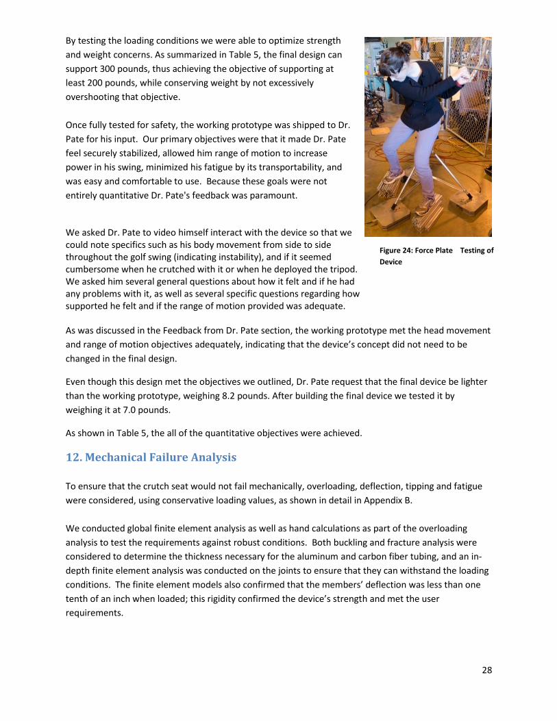
We needed to determine the loading conditions to analyze the strength of the device. As shown in
Figure 24, force plates were placed under the device and used to examine the loading conditions on it
throughout the golf swing. By stabilizing ourselves with the tripod seat as we swung, we were able to
determine the forces that will be applied to the tripod in its daily use.
As discussed in more detail in the Mechanical Failure Analysis section, having a better understanding of
the loading conditions allowed us to more accurately assess the device’s strength. The working
prototype's tube thickness was determined based on a conservative loading condition assumption.
Having a better approximation for the actual loading condition allowed us to determine that our
working prototype withstands 450 pounds, far surpassing the necessary 200 pounds. Overdesigning the
working prototype ensured its strength, but made it unnecessarily heavy.
28
By testing the loading conditions we were able to optimize strength
and weight concerns. As summarized in Table 5, the final design can
support 300 pounds, thus achieving the objective of supporting at
least 200 pounds, while conserving weight by not excessively
overshooting that objective.
Once fully tested for safety, the working prototype was shipped to Dr.
Pate for his input. Our primary objectives were that it made Dr. Pate
feel securely stabilized, allowed him range of motion to increase
power in his swing, minimized his fatigue by its transportability, and
was easy and comfortable to use. Because these goals were not
entirely quantitative Dr. Pate's feedback was paramount.
We asked Dr. Pate to video himself interact with the device so that we could note specifics such as his body movement from side to side throughout the golf swing (indicating instability), and if it seemed cumbersome when he crutched with it or when he deployed the tripod. We asked him several general questions about how it felt and if he had any problems with it, as well as several specific questions regarding how supported he felt and if the range of motion provided was adequate. As was discussed in the Feedback from Dr. Pate section, the working prototype met the head movement
and range of motion objectives adequately, indicating that the device’s concept did not need to be
changed in the final design.
Even though this design met the objectives we outlined, Dr. Pate request that the final device be lighter
than the working prototype, weighing 8.2 pounds. After building the final device we tested it by
weighing it at 7.0 pounds.
As shown in Table 5, the all of the quantitative objectives were achieved.
12. Mechanical Failure Analysis
To ensure that the crutch seat would not fail mechanically, overloading, deflection, tipping and fatigue
were considered, using conservative loading values, as shown in detail in Appendix B.
We conducted global finite element analysis as well as hand calculations as part of the overloading
analysis to test the requirements against robust conditions. Both buckling and fracture analysis were
considered to determine the thickness necessary for the aluminum and carbon fiber tubing, and an in-
depth finite element analysis was conducted on the joints to ensure that they can withstand the loading
conditions. The finite element models also confirmed that the members’ deflection was less than one
tenth of an inch when loaded; this rigidity confirmed the device’s strength and met the user
requirements.
Figure 24: Force Plate Testing of
Device
29
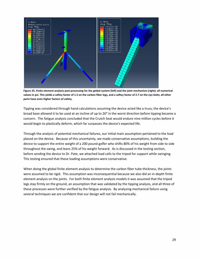
Figure 25. Finite element analysis post processing for the global system (left) and the joint mechanism (right); all numerical
values in psi. This yields a saftey factor of 1.5 on the carbon fiber legs, and a saftey factor of 2.7 on the eye bolts; all other
parts have even higher factors of safety.
Tipping was considered through hand calculations assuming the device acted like a truss; the device’s
broad base allowed it to be used at an incline of up to 26° in the worst direction before tipping became a
concern. The fatigue analysis concluded that the Crutch Seat would endure nine million cycles before it
would begin to plastically deform, which far surpasses the device's expected life.
Through the analysis of potential mechanical failures, our initial main assumption pertained to the load
placed on the device. Because of this uncertainty, we made conservative assumptions, building the
device to support the entire weight of a 200 pound golfer who shifts 80% of his weight from side to side
throughout the swing, and leans 25% of his weight forward. As is discussed in the testing section,
before sending the device to Dr. Pate, we attached load cells to the tripod for support while swinging.
This testing ensured that these loading assumptions were conservative.
When doing the global finite element analysis to determine the carbon fiber tube thickness, the joints
were assumed to be rigid. This assumption was inconsequential because we also did an in-depth finite
element analysis on the joints. For both finite element analysis models it was assumed that the tripod
legs stay firmly on the ground, an assumption that was validated by the tipping analysis, and all three of
these processes were further verified by the fatigue analysis. By analyzing mechanical failure using
several techniques we are confident that our design will not fail mechanically.

30
13. Manufacturing Plan: Working Prototype
The manufacturing of our device was fairly simple. Most of the parts were purchased directly from local suppliers or online. The parts that needed to be customized were within our range of experience. The final design consisted of three separate sub assemblies; leg assembly, center fixture assembly, and center column assembly. The leg assembly was manufactured first, then the center column assembly, and finally the center fixture assembly. For a detailed view of all parts and assemblies, see Appendix C .
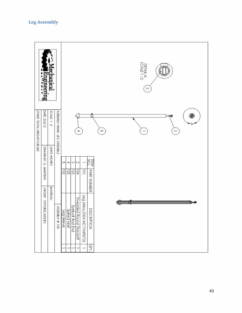
Leg Sub-Assembly
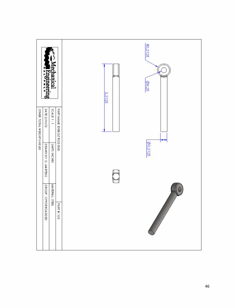
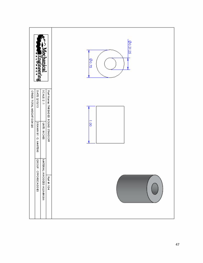
The leg sub-assembly is comprised of the aluminum shaft, foot, custom made sleeve, threaded round standoff, and threaded eyebolt. The aluminum shaft was made of higher strength 2024 aluminum tubing to ensure it could withstand the stresses associated with someone sitting on the tripod. Since the aluminum tubing comes in standard lengths of three feet, it was sized down using a saw and the ends sanded to remove any sharp edges. After the aluminum tubing was sized, a threaded round standoff made of alloy steel, was welded to the inside of one of the ends. To do this, 4 small holes were drilled into the aluminum tube a distance of 0.5 inches from the end. Then the standoff was placed inside the tube flush with the top edge and welded in place through the small holes. By using this technique, the finish was much cleaner than if welded on the top edge. The next step was to attach the custom made sleeve. The sleeve consisted of two parts: the aluminum tube and a 5/8in X 5/8in aluminum block. The sleeve was cut out of aluminum tubing with the inner diameter being the same dimension as the outer diameter of the leg shaft. The aluminum block was cut out of aluminum stock and then rounded on one side to be flush with the side of the sleeve. This block was then welded to the outside of the sleeve and a through hole drilled so that it could be attached to the middle connection bar. After the sleeve was attached, the last step was to attach the foot and screw in the threaded eyebolt. The foot was purchased online and fit to the leg with a tightening screw. The threaded eyebolt was screwed into the threaded standoff for the full length of the thread on the eyebolt. This process was repeated until all three legs are assembled.
Figure 26. 3D Model of
the Leg Assembly
31
Figure 28. 3D Model of the
Center Column Assembly
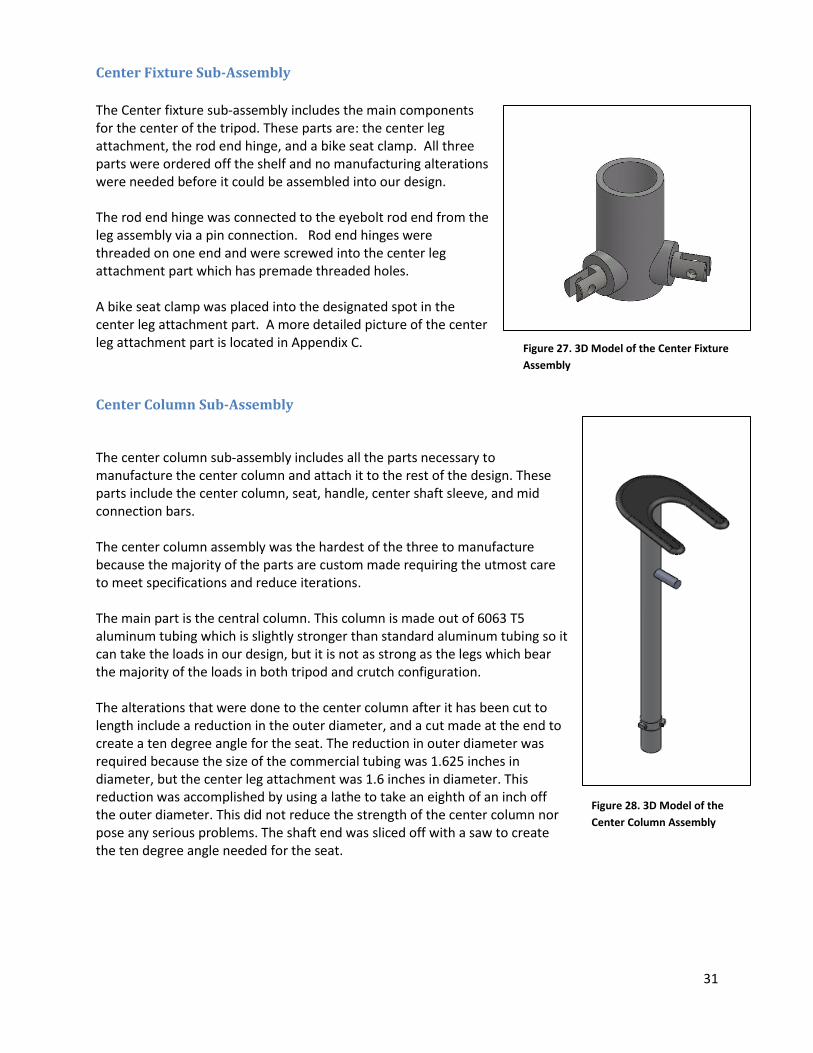
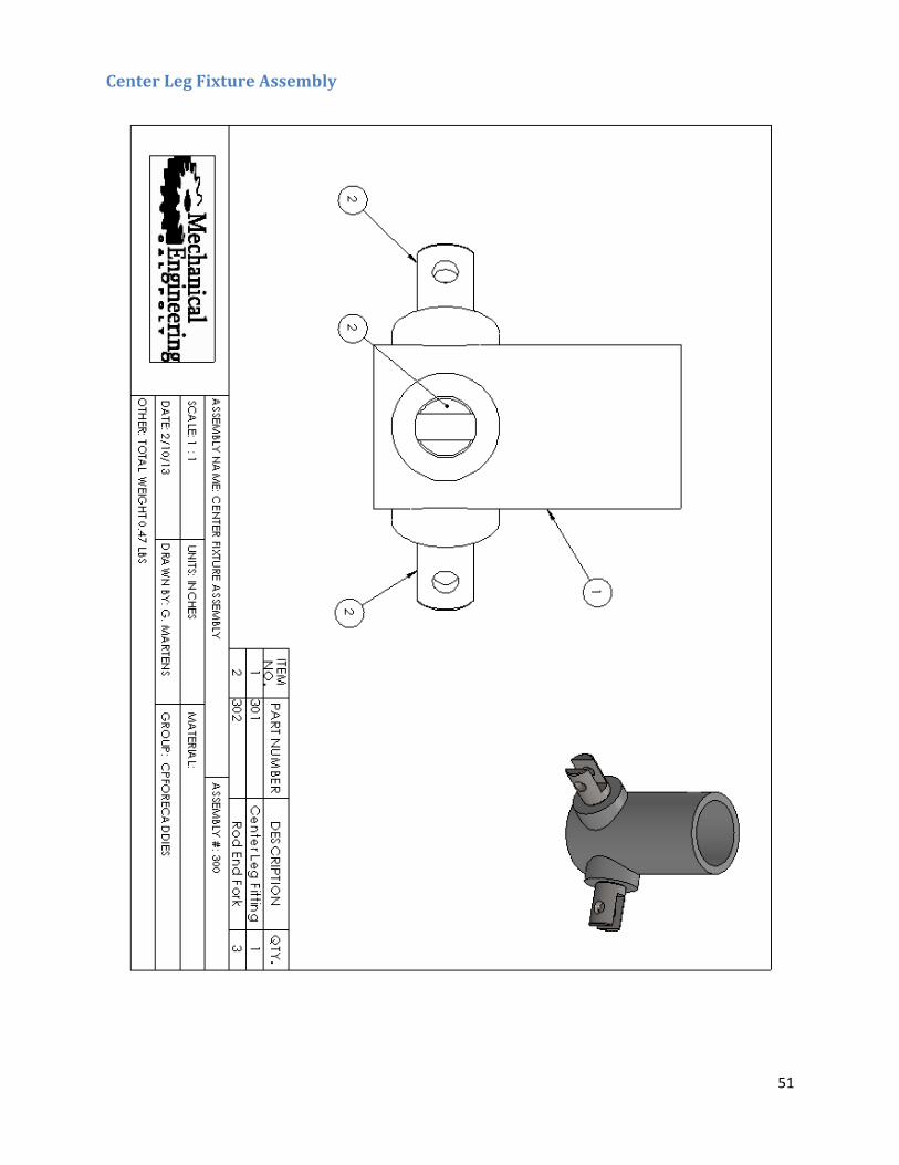
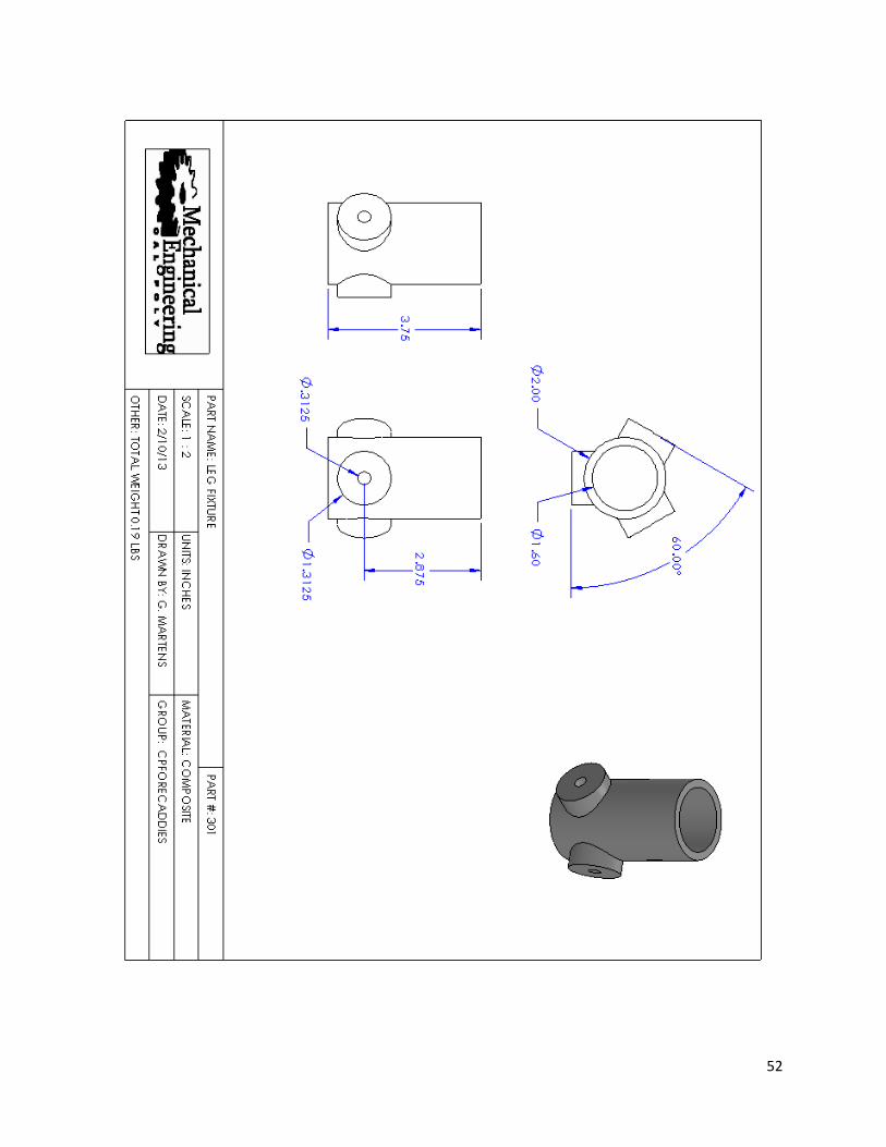
Center Fixture Sub-Assembly
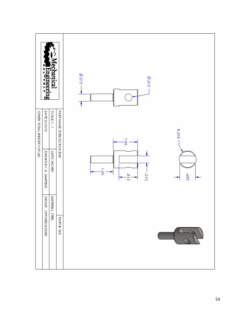
The Center fixture sub-assembly includes the main components for the center of the tripod. These parts are: the center leg attachment, the rod end hinge, and a bike seat clamp. All three parts were ordered off the shelf and no manufacturing alterations were needed before it could be assembled into our design. The rod end hinge was connected to the eyebolt rod end from the leg assembly via a pin connection. Rod end hinges were threaded on one end and were screwed into the center leg attachment part which has premade threaded holes. A bike seat clamp was placed into the designated spot in the center leg attachment part. A more detailed picture of the center leg attachment part is located in Appendix C.
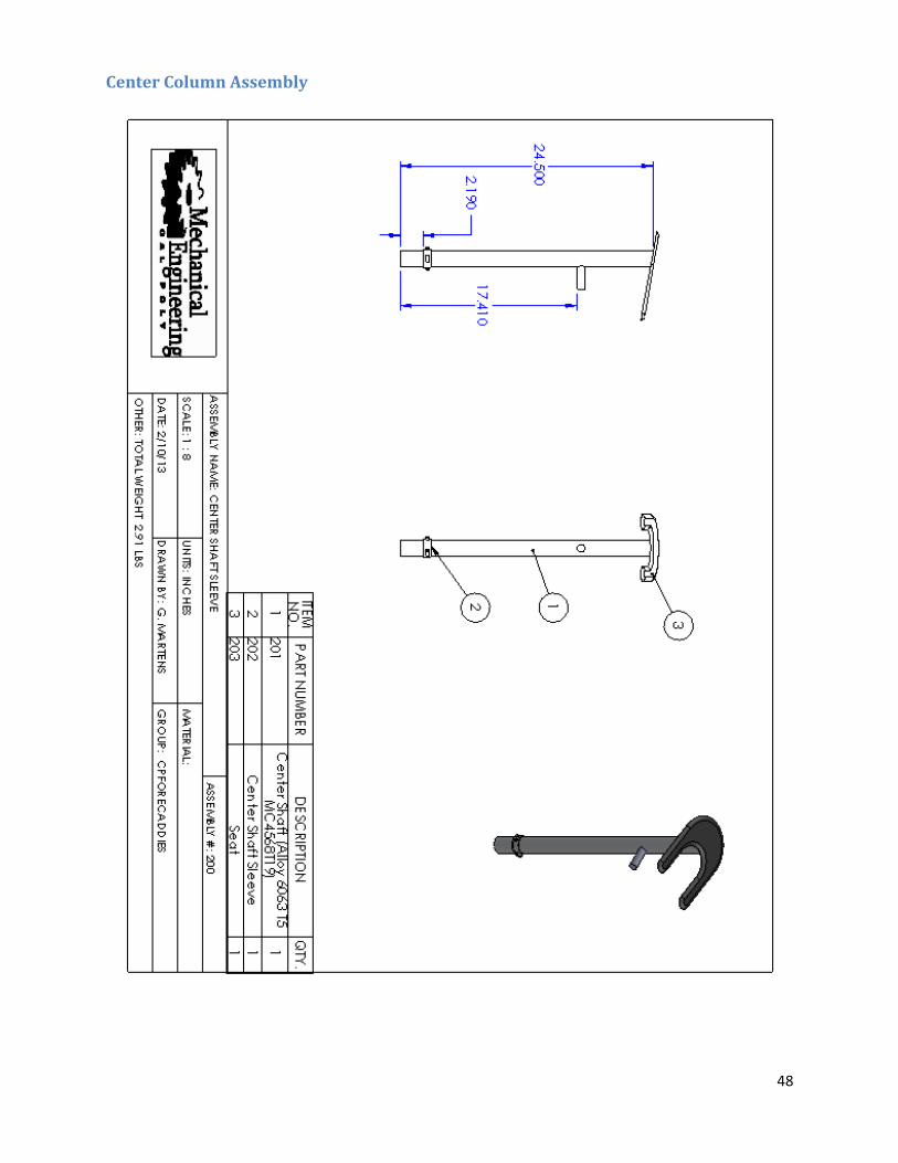
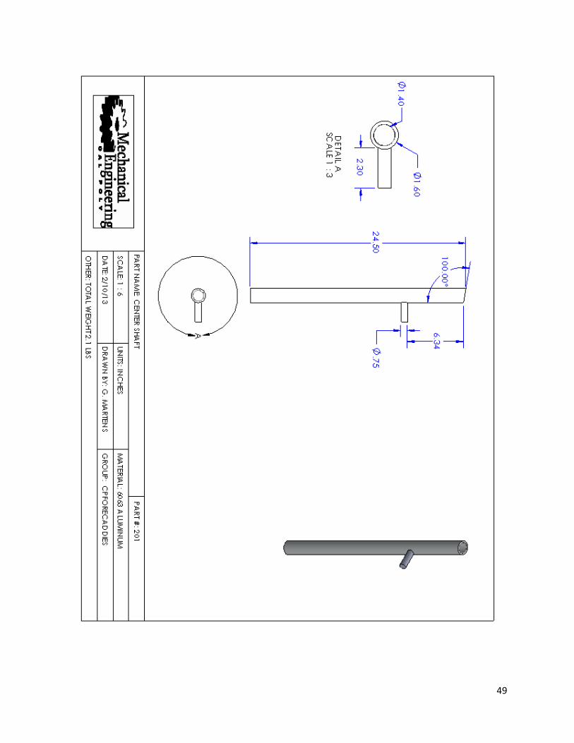
Center Column Sub-Assembly The center column sub-assembly includes all the parts necessary to manufacture the center column and attach it to the rest of the design. These parts include the center column, seat, handle, center shaft sleeve, and mid connection bars. The center column assembly was the hardest of the three to manufacture because the majority of the parts are custom made requiring the utmost care to meet specifications and reduce iterations. The main part is the central column. This column is made out of 6063 T5 aluminum tubing which is slightly stronger than standard aluminum tubing so it can take the loads in our design, but it is not as strong as the legs which bear the majority of the loads in both tripod and crutch configuration. The alterations that were done to the center column after it has been cut to length include a reduction in the outer diameter, and a cut made at the end to create a ten degree angle for the seat. The reduction in outer diameter was required because the size of the commercial tubing was 1.625 inches in diameter, but the center leg attachment was 1.6 inches in diameter. This reduction was accomplished by using a lathe to take an eighth of an inch off the outer diameter. This did not reduce the strength of the center column nor pose any serious problems. The shaft end was sliced off with a saw to create the ten degree angle needed for the seat.
Figure 27. 3D Model of the Center Fixture
Assembly

32
The initial plan for the seat was to cut the desired shape out of quarter-inch aluminum sheet and then have it upholstered by a local shop. The seat was then attached by welding it on the angled end of the center column so that the seat is angled towards the ground. The inner curved surface of the seat was placed as close to the outer surface of the center column as possible to evenly distribute the load on the seat. Because the seat must be comfortable enough to sit on, and also strong enough to support the forearm when used as a crutch, there were multiple iterations of the design before a final one was chosen. Instead of manufacturing it out of aluminum, the final seat was manufactured from carbon fiber. By using carbon fiber, the design is more ergonomic and yet maintains the lightweight quality of aluminum. Just like in the manufacturing of the leg shaft sleeve, the center column sleeve was made using the same process. An aluminum tube was cut down to the appropriate height for the sleeve part and three aluminum blocks that had been curved on one end were welded to this sleeve. Holes were drilled in the aluminum block so that they could be connected to the mid connection bars via pins. The mid connection bars were cut to length out of 7/2 x 5/8 inch stock aluminum bar. Each bar has two slots cut out on each end and a through hole drilled perpendicular to the slot. The middle connection bars were then mated to the sleeves on the leg shaft and the center column to allow for the center column to pull up or release the legs when switching between crutch and tripod configuration. The final part for the center column assembly is the handle. The handle was cut to length out of stock aluminum rod with a half-inch diameter. This was then welded to the center column seven inches below the surface of the seat.
Assembling the Working Prototype
Once all sub-assemblies had been manufactured, the final design was put together. The first step was to attach the three leg assemblies. To do this, each eyebolt rod end of the leg assemblies was pinned to the rod end hinges of the center leg fixture assembly. After the three legs were attached, the center column assembly was put in place. The center column slides down into the opening in the leg fixture until the handle rests on the top surface. To fix it in place, the bike seat clamp was tightened. This was to make sure that when attaching the mid connector bars, the center column was fixed. The final part to attach was the mid connector bars. These were pinned in place on the center column sleeve first, and then the leg sleeve. After these were attached, the final design was assembled. The center column slides easily through the leg fixture, pulling the legs up to a vertical position, and slides down extending the legs into the tripod configuration. For a more detailed look at the assembly of the final design see Appendix C.
33
14: Manufacturing Plan: Final Product After feedback was gathered from Dr. Joshua Pate, the working prototype was updated to further
customize the product to meet Dr. Pate's requirements. The device with these updates became our final
product. The entire center column sub-assembly was retained from the working prototype enabling the
team to focus on creating a new leg sub-assembly and new mid-connection bars. Changes to these
components would allow for the device to meet Dr. Pate's specifications.
Leg Sub-Assembly
Because the aluminum legs were dense, added a lot of unnecessary weight and were too long, we
decided to remake the entire leg sub-assembly.
Instead of using aluminum for the legs, we switched to carbon fiber because it was stronger and lighter
than aluminum. We purchased a 6 foot tube of carbon fiber with an outer diameter of 0.84 inches and
cut it into 3 pieces. Two pieces were cut to 15-9/16 inches and the third leg was cut to 16-7/16 inches.
The lengths were predetermined analytically based on of Dr. Pate's desired heights for both crutching
and sitting.
Based on carbon fiber research and discussions with Dr. Mello, Mechanical Engineering, we realized that
it is very difficult to glue aluminum to carbon fiber. The best metal to adhere to carbon fiber is steel, and
for our purposes, we decided to utilize stainless steel in an effort to prevent rust. To achieve this we
machined all new leg sleeves and standoffs.
The stainless steel standoffs were designed with a lip to provide extra support and strength since the
standoff was going to be glued into the carbon fiber leg. Our raw material was a foot long stainless steel
type 304/304L rod with an outer diameter of 7/8 inch. This was the smallest length of rod available on
the market. The rod was placed in a lathe and the ends were turned down about an inch in length to a
diameter of about 0.82 inches. These ends were cut off with a cut saw leaving about a 1/3 inch lip. A
hole was drilled down the center of each of these standoffs and then the holes were threaded.
Next, we made the stainless steel sleeves. Our raw material was a stainless steel type 304/304L rod with
an outer diameter of 1-3/16 inches. A hole was drilled to a diameter of 0.85 inches in the rod on the
lathe and then three cuts were made, using a cut saw to produce three sleeves. It is important to note
that when drilling the hole in the rod, multiple drill bits had to be used and stepped up from a smaller
size bit to a larger one in order to drill a hole of the magnitude needed in the hard stainless steel.
Following the manufacturing of the sleeves, the connection point for the mid-connector bars to the new
sleeves was manufactured. Our raw material was a one foot stainless steel type 304/304L bar stock
with a thickness of 5/16 inches and a width of an inch. Three 3/4 inch sections were cut off of this bar
stock and then holes were drilled widthwise through each of these pieces before welding them to our
stainless steel sleeves.
34
Next, the sleeves and the standoffs were glued to the carbon fiber legs. We used a 3M adhesive
cartridge, DP460NS high strength epoxy for vertical surfaces with the glue gun from the materials
engineering lab. To provide a better surface for the glue to adhere, each leg was sanded where the piece
was going to be attached. We also sanded and applied acetone to remove and dust or oil from all of the
stainless steel pieces. The glue was then applied to the parts and they were then inserted into place the
manufactured legs. All glued surfaces were duct taped to maintain pressure while the glue hardened.
The glue adhesive was allowed to dry for approximately two days. The duct tape was removed and we
added Tornado brand feet to the three carbon fiber legs.
New Mid-Connector Bars
To accommodate the new geometry for differing leg heights, new mid connector bars were
manufactured. Our raw material was a 6 foot multipurpose aluminum alloy 6061 bar with a thickness of
5/16 inches and a width of an inch. We cut the bar into three pieces; two pieces were cut to a length of
10-1/4 inches and a third piece was cut to 13-5/16 inches. Slots were cut into each end of the bars
about 1.2 inches deep and holes were drilled through the slot ends hanging out. This was to allow for a
seamless connection to the sleeves and center column assembly.
In order to reduce weight and add some character to the design, 1/2 inch holes were drilled into the
center part of the mid-connectors. These holes were spaced an inch apart from center to center.
Assembling the Final Product
The legs were screwed into the threaded eyebolts that were already attached to the center column
assembly. Then the mid connectors were screwed into the center column assembly and the sleeves on
the legs. The product was then tested to ensure that it functioned properly.
Repair and Maintenance
Since the assembly of the final design was simple and made of only three sub assemblies, it will be easy
to replace a part if one breaks or replace a sub assembly with a new one. For all the parts of the leg
assembly, the only parts that would require a full replacement if broken are the sleeve and the threaded
round standoff. These were welded permanently to the leg shaft and, in the case of the sleeve, custom
made. If the leg shaft itself fractures, the leg must be completely replaced. Because of the leg
assembly’s simplistic design, it can be manufactured in a small amount of time and installation only
requires the eyebolt rod end to be pinned to the rod end hinge.
Since all the parts in the center fixture assembly are readily available commercially, they can easily be
replaced if one breaks. However, some disassembly is required to remove the broken parts since the
other assemblies all connect to the center fixture. The disassembly would include unpinning the mid
connector bars from the legs and center column, removing all three legs, and then sliding the center
column out of the leg fixture. Once disassembled, it becomes very easy to replace any broken parts in
the center fixture assembly.
35
The repair of any part in the center column assembly requires a full replacement of the assembly. This is
because all the parts in this assembly are custom made and welded to the center column. If one breaks,
a new center column assembly must be manufactured and shipped to the user. On the other hand,
installation of the replacement is simple and only requires the mid connector bars to be disconnected,
and then reconnected once the center column is in place.
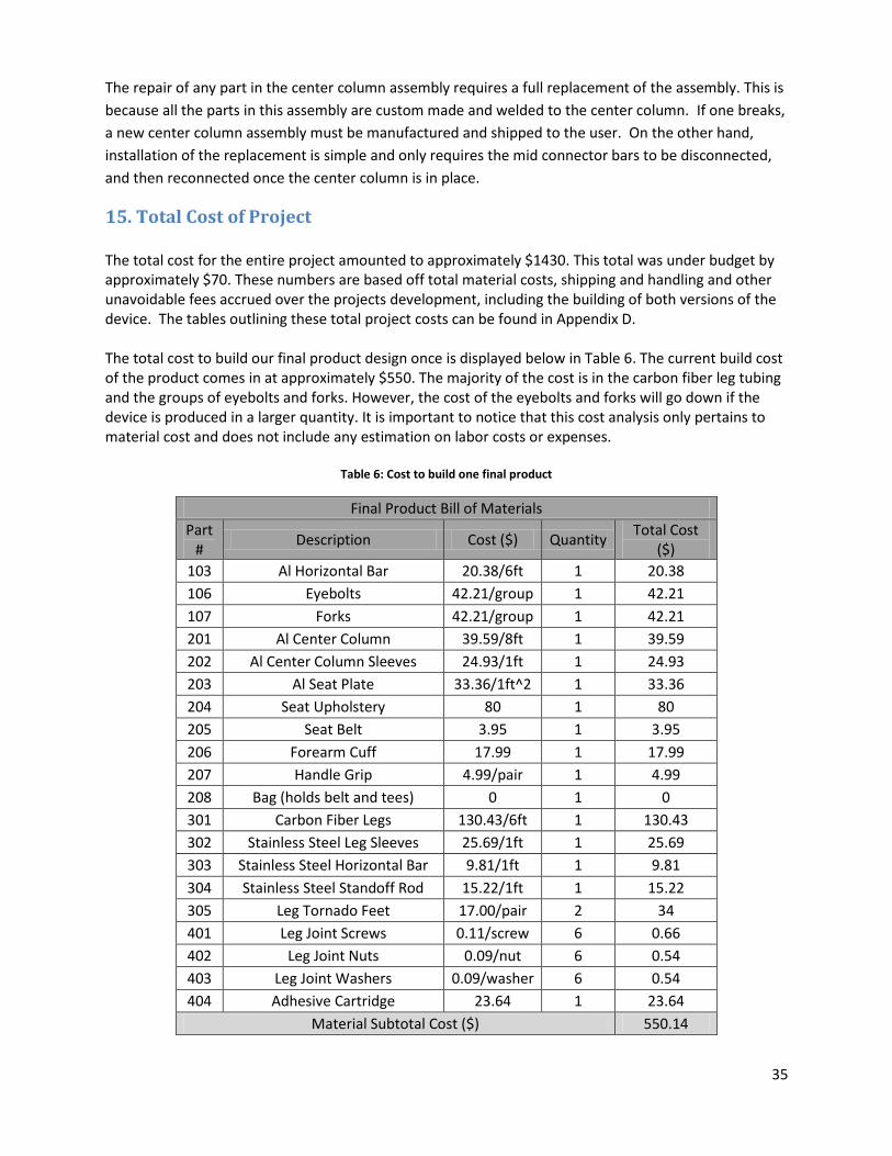
15. Total Cost of Project The total cost for the entire project amounted to approximately $1430. This total was under budget by approximately $70. These numbers are based off total material costs, shipping and handling and other unavoidable fees accrued over the projects development, including the building of both versions of the device. The tables outlining these total project costs can be found in Appendix D. The total cost to build our final product design once is displayed below in Table 6. The current build cost of the product comes in at approximately $550. The majority of the cost is in the carbon fiber leg tubing and the groups of eyebolts and forks. However, the cost of the eyebolts and forks will go down if the device is produced in a larger quantity. It is important to notice that this cost analysis only pertains to material cost and does not include any estimation on labor costs or expenses.
Table 6: Cost to build one final product
Final Product Bill of Materials
Part #
Description Cost ($) Quantity Total Cost
($)
103 Al Horizontal Bar 20.38/6ft 1 20.38
106 Eyebolts 42.21/group 1 42.21
107 Forks 42.21/group 1 42.21
201 Al Center Column 39.59/8ft 1 39.59
202 Al Center Column Sleeves 24.93/1ft 1 24.93
203 Al Seat Plate 33.36/1ft^2 1 33.36
204 Seat Upholstery 80 1 80
205 Seat Belt 3.95 1 3.95
206 Forearm Cuff 17.99 1 17.99
207 Handle Grip 4.99/pair 1 4.99
208 Bag (holds belt and tees) 0 1 0
301 Carbon Fiber Legs 130.43/6ft 1 130.43
302 Stainless Steel Leg Sleeves 25.69/1ft 1 25.69
303 Stainless Steel Horizontal Bar 9.81/1ft 1 9.81
304 Stainless Steel Standoff Rod 15.22/1ft 1 15.22
305 Leg Tornado Feet 17.00/pair 2 34
401 Leg Joint Screws 0.11/screw 6 0.66
402 Leg Joint Nuts 0.09/nut 6 0.54
403 Leg Joint Washers 0.09/washer 6 0.54
404 Adhesive Cartridge 23.64 1 23.64
Material Subtotal Cost ($) 550.14
36
16. Conclusion The result of this project is a fully functioning crutch seat ready for Dr. Pate to use on the golf course.
The crutch seat is lightweight and portable, weighs 7lbs and allows Dr. Pate to swing commercial golf
clubs. It provides the required support and stability that Dr. Pate requires, and will not damage the golf
course in any manner. The device supports a weight of 300lbs without yielding and can work
consistently for an 18-hole round of golf. This golf crutch seat design is ideal for Josh Pate because it acts
as a forearm crutch allowing him to transport himself in the manner he is accustomed to and when
deployed provides enough support and stability for him to free his hands and swing with both arms to
achieve increased power and distance in his golf game.
Through the help of a generous grant from the National Science Foundation and help and guidance from
Dr. Kevin Taylor, Chair of the Kinesiology Department, and Professor Sarah Harding from the
Mechanical Engineering Department, we were able to design and build a device to help Dr. Josh Pate
better enjoy playing the game of golf. Hopefully the success of this project will encourage others with
similar difficulties to pick up the game and start playing.

37
Appendix A: Quality Function Deployment (“House of Quality”)
38
The Quality Function Deployment (QFD) diagram summarizes customer requirements and target
objectives noting the correlation and the importance of each item. It also considers competing devices
and how well they meet our requirements. Customers' (Josh Pate and Tony Bennett) requirements are
listed based on the importance to them on a scale of 1-5 with 5 being most important. The intersection
of the specifications and the customer requirements are weighted on a scale of 1-9 with 9 having the
highest correlation. Only weights 1, 3, and 9 were used. Four competing devices and their correlations
are listed on the right side of the matrix and immediately below the correlation matrix. The bottom
section of the diagram represents our target goals. Our team calculated the importance of each item in
reaching our goal and that is reflected in the bottom two rows.
39
Appendix B: Analysis
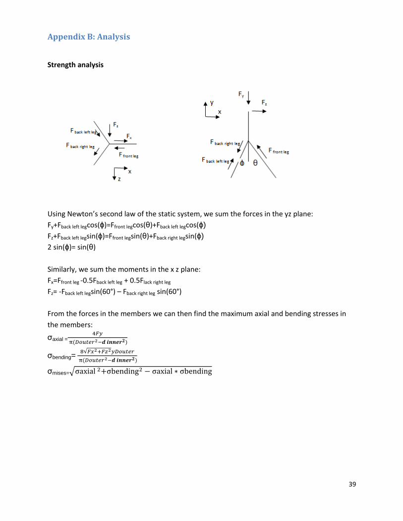
Strength analysis
Using Newton’s second law of the static system, we sum the forces in the yz plane:
Fy+Fback left legcos(ϕ)=Ffront legcos(θ)+Fback left legcos(ϕ)
Fz+Fback left legsin(ϕ)=Ffront legsin(θ)+Fback right legsin(ϕ)
2 sin(ϕ)= sin(θ)
Similarly, we sum the moments in the x z plane:
Fx=Ffront leg -0.5Fback left leg + 0.5Flack right leg
Fz= -Fback left legsin(60°) – Fback right leg sin(60°)
From the forces in the members we can then find the maximum axial and bending stresses in
the members:
σaxial =
σbending=
σmises=
40
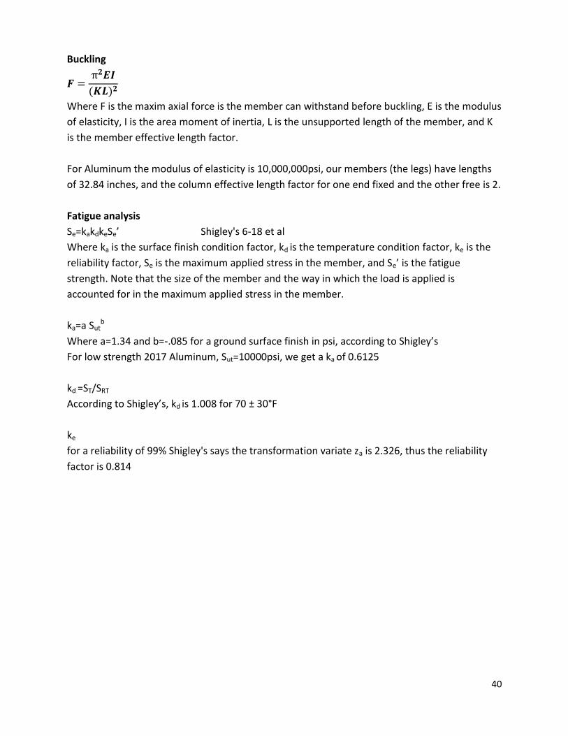
Buckling
Where F is the maxim axial force is the member can withstand before buckling, E is the modulus
of elasticity, I is the area moment of inertia, L is the unsupported length of the member, and K
is the member effective length factor.
For Aluminum the modulus of elasticity is 10,000,000psi, our members (the legs) have lengths
of 32.84 inches, and the column effective length factor for one end fixed and the other free is 2.
Fatigue analysis
Se=kakdkeSe’ Shigley's 6-18 et al
Where ka is the surface finish condition factor, kd is the temperature condition factor, ke is the
reliability factor, Se is the maximum applied stress in the member, and Se’ is the fatigue
strength. Note that the size of the member and the way in which the load is applied is
accounted for in the maximum applied stress in the member.
ka=a Sutb
Where a=1.34 and b=-.085 for a ground surface finish in psi, according to Shigley’s
For low strength 2017 Aluminum, Sut=10000psi, we get a ka of 0.6125
kd =ST/SRT
According to Shigley’s, kd is 1.008 for 70 ± 30°F
ke
for a reliability of 99% Shigley's says the transformation variate za is 2.326, thus the reliability
factor is 0.814
41
Appendix C: Assembly and Subassembly Drawings
Full Assembly
Tripod Configuration

42
Crutch Configuration
43
Leg Assembly

44

45
46
47
48
Center Column Assembly
49

50
51
Center Leg Fixture Assembly
52
53
54

55
Appendix D: Total Project Cost
Total Bill of Materials
Part # Description Cost ($) Quantity Total Cost ($)
101 Al Legs 34.53/8ft 3 103.59
102 Al Leg Sleeves 11.74/1ft 2 23.48
103 Al Horizontal Bar 20.38/6ft 2 40.76
104 Al Round Standoff 12.93/1 4 51.72
105 Leg Rubber Feet 3.95/1 3 11.85
106 Eyebolts 42.21/group 1 42.21
107 Forks 42.21/group 1 42.21
201 Al Center Column 39.59/8ft 1 39.59
202 Al Center Column Sleeves 24.93/1ft 2 49.86
203 Al Seat Plate 33.36/1ft^2 1 33.36
204 Seat Upholstery 80.00 1 80.00
205 Seat Belt 3.95 1 3.95
206 Forearm Cuff 17.99 1 17.99
207 Handle Grip 4.99/pair 1 4.99
208 Bag (holds belt and tees) 0.00 1 0.00
301 Carbon Fiber Legs 130.43/6ft 1 130.43
302 Stainless Steel Leg Sleeves 25.69/1ft 1 25.69
303 Stainless Steel Horizontal Bar 9.81/1ft 1 9.81
304 Stainless Steel Standoff Rod 15.22/1ft 1 15.22
305 Leg Tornado Feet 17.00/pair 2 34.00
401 Fasteners 33.06 1 33.06
402 Adhesive Cartridge 23.64 1 23.64
Material Subtotal Cost ($) 817.41
Additional Costs
Description Cost ($) Quantity Total Cost
($)
Welding 17.00/hr 10 170.00
Shipping of Device 80.00 3 240.00
Shipping & Handling 160.67 - 160.67
Poster Board 5.64 1 5.64
Stainless Steel Filler Rod 28.37 1 28.37
Additional Subtotal Cost ($) 604.68
CpForecaddie Total Project Cost
Material Cost ($) 817.41
Additional Cost ($) 604.68
Project Total ($) 1422.09
Remaining Budget ($) 77.91

56
Appendix D: Bibliography A WalkEasy Inc. "Model 495" Product Description. Information retrieved October 13, 2012.
http://www.walkeasy.com/shop/product_details.asp?ProductCode=495
B Mayo clinic. “Tips for choosing and using canes” Information retrieved October 13, 2012.
<http://www.mayoclinic.com/health/canes/HA00064>
C Ottobock. "ParaGolfer" Product Description. Information retrieved September 29, 2012.
<http://www.ottobockus.com/cps/rde/xchg/ob_us_en/hs.xsl/46173.html>
D Kraeft, Sr. “Support for a Disabled Golfer” Patent 6,564,802. May 20, 2003.
<http://www.google.com/patents/US6564802?pg=PA10&dq=apparatus+for+swinging+a+golf+club+disa
bility&hl=en&sa=X&ei=4rxxULiWKqO6iwKrnYDIBw&ved=0CEcQ6AEwCA#v=onepage&q=apparatus%20fo
r%20swinging%20a%20golf%20club%20disability&f=false>
E Zimmerman, Dennis. “Swingfree Crutch” Patent 5,318,058. June 7, 1994. http://www.google.com/patents?id=53J8AAAAEBAJ&printsec=abstract&zoom=4#v=onepage&q&f=false F Golf Country “Specially Fit Golf Clubs” http://www.golf-country.com/adaptive_golf/ G . Hammarcher Schlemmer. "The 33-In-1 Golf Club" Product Description”. Information retrieved
September 29, 2012.
<http://www.hammacher.com/product/81021?source=PRODSEM&cm_ven=HS&cm_cat=ProductSEM&
cm_pla=AdWords&cm_ite=81021>
HBudynas, Richard G. and J. Keith Nisbett. Shigley's Mechanical Engineering Design Ninth Edition.
McGraw-Hill Companies, Inc. New York, NY. 2008.


![Object-oriented programming of adaptive finite element …jinnliu/proj/Device/1996OOP.pdf · Object-oriented programming of adaptive finite element and ... adaptive analysis ... [36]](https://static.fdocuments.us/doc/165x107/5b14d55b7f8b9af15d8c1bb0/object-oriented-programming-of-adaptive-finite-element-jinnliuprojdevice-.jpg)