Adaptive Escape Routing - inotec-licht.de · Explanatory Leaflet Adaptive Escape Routing Publisher:...
52
Safety & Security Division ZVEI I EXPLANATORY LEAFLET Advancement of technical building evacuation: From dynamic to adaptive escape routing Adaptive Escape Routing 33013:2017-01
-
Upload
vuongtuyen -
Category
Documents
-
view
224 -
download
0
Transcript of Adaptive Escape Routing - inotec-licht.de · Explanatory Leaflet Adaptive Escape Routing Publisher:...

Safety & Security Division
ZVEI I EXPLANATORYLEAFLET
Advancement of technical building evacuation: From dynamic to adaptive escape routing
Adaptive Escape Routing
33013:2017-01
2
Despite the utmost care, ZVEI assumes no liability for the content. All rights, in particular those relating to the storage, reproduction, distribution and translation, are reserved.
Impressum
Explanatory LeafletAdaptive Escape Routing
Publisher:German Electrical and Electronic Manufacturers’ AssociationSafety & Security DivisionLyoner Straße 960528 Frankfurt am Main
Telephone: +49 69 6302-272Fax: +49 69 6302-322E-mail: [email protected]
Responsible:Peter KrappSafety & Security Division
January 2017
Authors
Bernd Ammelung Markus BrüneDr. Sebastian FestagProf. Dr. Roland GoertzReiner HitzemannUlrich HöferKarl-Olaf KaiserPeter KrappNorbert KüsterHans KupferFriedrich MünzBastian NagelMarco PlaßLance RütimannDr. Henning SaliéMichael SigesmundRené TepaßNorbert VogelGünter Wagner-Gittel
Ing.-Büro Ammelung, Security ConsultingRuhr-Universität BochumHekatron Vertriebs GmbHBergische Universität WuppertalABB Kaufel GmbHInotec Sicherheitstechnik GmbHBPK GmbH und Kaiser-BrandschutzseminareZVEI - FV SicherheitRechtsanwaltSiemens AGSiemens AG Hekatron Vertriebs GmbHUniversität PaderbornSiemens Schweiz AG rhs technik kommunizierenInternational Security Academy e.V.Novar GmbHBosch Sicherheitssysteme GmbHCEAG Notlichtsysteme GmbH
1112 left12 middle12 right1416 top16 down192030303131323333353637383940414243
Size
HekatronAlona_S/Fotolia
Freepik.comVirtua73/Fotolia
HekatronHekatronHekatronHekatronHekatron
InotecInotecInotecInotecInotecInotecInotecInotecInotecInotec
Kempen Krause Hartmann Ingenieure GmbHKempen Krause Hartmann Ingenieure GmbH
InotecInotec
Smuay/FotoliaUniversität Paderborn/C.I.K.
Pictures
3
Contents
5
6
8
9
11
11
12
13
13
15
19
23
23
23
24
25
26
27
28
28
29
30
35
44
45
48
Preface
Introduction
Objective and scope of application
Legal framework
Adaptive escape routing
4.1 General distinction of elements
4.2 Optical marking and signalling
4.3 Acoustic signalling
4.4 Concepts for escape routing
4.5 Classification and conceptual definition
Risk scenarios
Benefits of adaptive escape routing
6.1 Safety enhancement
6.2 Gaining time
6.3 Utilization of escape routes adapted to the situation
6.4 Avoidance of panicky behaviour
6.5 Emergency rescue service
6.6 Consideration of particular groups via the 2-senses principle
6.7 Probability of default and flexibility
6.8 Compensations
6.9 Economic efficiency
The concept of adaptive escape routing
Application examples of escape routing
Future advancement and need for action
List of references
Appendix
1.
2.
3.
4.
5.
6.
7.
8.
9.

4

5
Preface
For a few years now, the ZVEI Safety & Security Division works on the contribution that systems engineering can support to building evacu-ation. The outcome of these works can be found in a brochure entitled “Effective building evacuation” [Effektive Gebäudeevakuierung] (EffGeb-EvMSyst, 1/2012) and an appendix with technical details (AnEffGebEvM-Syst, 8/2011). This explanatory leaflet complements these documents.
It shows how different technical systems can be developed into an adaptive systems engineering technology by intelligent links between hazard identification, alerting and evacuation. Thus, adaptive systems engineering technology allows the adaptation of “escape routing” by taking into consideration changing developments of a hazardous situation, in particular fire development.
Discussion on this topic is not only fostered by technological development. Particularly vulnerable individuals like the growing number of elderly often suffering from reduced mobility, pregnant women, children and disabled persons as well as larger and more complex building structures generate new requirements for solutions that are up-to-date and secure in case of demand. The development and market availability of novel systems that allow to cover risks, that beforehand were not or only difficult to manage at reaso-nable costs, lead to further need for action.
There is an obvious trend to use adaptive escape routing with intelligent readjustment of the safety system technology to the development of a hazardous situation. The pre-sent explanatory leaflet describes the concept of adaptive escape routing and is intended to make a future-oriented contribution to optimize the evacuation of buildings. We have embarked upon a development that can increase our security level – at the same time potentially occurring, new hazards have to be analysed and integrated into further deve-lopments. The primary objective is the enhancement of safety. The aim of this explanato-ry leaflet is to inform about basic technological opportunities and to point out needs for action within the fields of technology, science, standardisation and application.
Frankfurt am Main, 26th January 2017
Dr. Sebastian Festag Chairman of the Working Group Adaptive escape routing

6
1.
Today technological measures which support the evacuation of buildings are mainly used as a compensation, if safety regulations cannot be reached by usual means due to building specific conditions. However, technological measures enable a flexible design and help circumvent dilemmas (especially with regard to existing buildings). The achievement of the required safety level is the most important measure of all. Technology, however, only obtains a high level of acceptance if it is economically ef-ficient. This can be obtained by individually tailored strategies in which technological measures are integrated.
The risk spectrum from which requirements for the design of buildings emerge is lar-ge. Hence, there is a range of factors influencing building evacuation. All individuals that are within a building in an emergency have to leave the building unharmed and be able to safely reach the outside or rescue themselves into a safe area without the help of a third party. Therefore, requirements for planners and operators of buildings are high with regard to an evacuation in the event of an emergency.
Within the field of fire protection, the term systems engineering has become common for technological measures; it is referring to systems engineering measures. Tech-nological measures are not reduced to fire protection only. They offer optimization potential to achieve a targeted level of safety and help to increase this level. The integration of the 2-senses principle serves as a good example as this principle addresses at least two senses for issuing a warning notice and to support evacuati-on in case of an emergency. Individuals who are disadvantaged in the perception of surrounding stimuli are often neglected to some extent, although this shall be prevented by the so-called German Equal Opportunities for People with Disabilities Act (BGG v. 27.4.2002, recently changed by Art. 12 G v. 19.12.2007, BGBl. 2007 I 3024). This equal treatment also applies to and is especially important for the evacuation of buildings, as in this case, a limited perceptive faculty and hence, a delayed self-rescue in an emergency may result in serious consequences. Furthermore, the needs of individuals with multiple disabilities have to be taken into account in the planning stage of the evacuation of a building. Only an individually targeted combination of constructional, organisational and (systems) technological measures can be taken into consideration that depend on local operating and spatial conditions. For example, spe-cifically trained or instructed personnel can be employed for supporting self-rescue of other individuals. Especially in complex buildings or buildings with many visitors who are unfamiliar to the area, those measures quickly reach their limits. In work places (cf. ASR 2.3, 2014), necessary measures have to be individually defined for each particularly vulnerable employee, in order to ensure their self-rescue in the event of an emergency.
Introduction
The 2-senses principle: All information from the environment
is perceived by human beings via senses.If one sense fails, the perception of the
information by another sense is essential.Information therefore has to be accessible
for at least two of the three senses “hearing, seeing, touching” with the help
of the two-senses principle (e. g. optical and acoustic alerting at the same time)
(cf. ASR V3a.2, 2012, DIN 18040-1, 2010 and DIN 18040-2, 2011).

7
Systems engineering measures can reduce the number of people who are in need of organisational support in the event of an evacuation and hence, lower staff require-ments and therefore costs. Available auxiliary personnel can focus on those persons who are not able to rescue themselves as well as on injured people.
Groups of people who may potentially be restricted in their self-rescue abilities like children, elderly, disabled persons and pregnant women are especially in need of protection. On the one hand, the demographic change increases the share of elderly within our society. Furthermore, life expectancy increases which generally results in a reduction of mobility. Moreover, the number of obese people increases (Spitzer, 2015, P. 32 ff.). A steady urbanization (formation of metropolitan areas), in turn, leads to larger and more complex building structures.
On the other hand, opportunities for assistance and aided rescue have always been and will always be limited due to external conditions. For fire dynamic reasons how-ever, it is unacceptable to await the arrival of rescue teams before starting with the rescue of people. The securing of possibilities for sufficient self-rescue is hence indis-pensable under all circumstances and is given highest priority. In order to successfully support the self-rescue of the building users, hazard identification at an early stage is a mandatory prerequisite. The added value of the concept of adaptive escape routing results from the combination of different technological systems which flexibly react to the development of a hazardous situation.
The security and the achievement of the protection objective is improved mainly by supporting the routing of people via accessible escape routes and by reducing the risk of disorientation and undesired (e.g. panicky) behaviour.

8
2. Objective and scope of application
This explanatory leaflet primarily addresses architects, specialised planners, public authorities and fire brigades which are involved in planning, creation, approval and acceptance of evacuation concepts, as well as operators of structural works who are responsible for the safety of their building’s users.
The explanatory leaflet illustrates the current state of debate on escape routing and outlines the development of active and dynamic to adaptive escape routing, a concept which is based on a “dynamic control loop with a feedback loop“. It links measures of different fields whereas constructional, technological, organisational and defensive measures are interlocked. This concept represents an advancement of dynamic escape routing.
The concept’s objective is to optimize secure self-rescue. Escaping people shall be guided out of the building or into secure areas within the building with the help of technological measures that consider spatial and time-related conditions and the development of the hazardous situation. However, a secure evacuation is not neces-sarily linked to a short evacuation time. Therefore, the circumvention of hazards by avoiding threats for human life and health is decisive.
Taking into consideration the 2-senses-principle and new technological elements, the concept of adaptive escape routing goes beyond today’s common practice.
The shortest escape route is not always the most secure one.

9
3. Legal framework
The assurance of building users’ self-rescue in the event of an emergency (e.g. in the event of fire, amok or terror attacks or other hazardous situations) is a primary protec-tion objective for developers, building operators and planners. This follows already – independent of fire prevention objectives of Sub-Federal Building Regulations – from the German Constitution which defines the protection of human life and health as highest legal value second only to the assurance of human dignity (German Constitu-tion, Art. 2 Abs. 1 GG). This is followed by the right to property (Art. 14 GG) and the protection of established and exercised business (Art. 12 GG).
This leads to a legal obligation for developers or building operators to plan, construct and operate their buildings in a way that all people present in the building remain unharmed in a hazardous situation at any time. Individuals have to be able to leave the building or escape into a secure part of the building on their own as quickly as possible. Protection concepts, especially fire protection concepts, are to be designed in such a way that in the event of fire the building is fully evacuated without the supportive intervention of the fire brigade. The developer/operator must not base his/her planning on the support of the fire brigade or other external assistance for the rescuing of his/her building’s users.
For this reason, the highest construction supervision authorities of the Federal States pointed out in their “Policy paper smoke extraction“ [Grundsatzpapier Entrauchung] (Famers & Messerer, 2008) that fire protection planning of a building has to ensure the completion of self-rescue at the point of arrival of the fire brigade as the fire bri-gade cannot ensure the rescue of persons in special buildings with many people. Upon arrival, the fire brigades efforts rely on persons having mostly left the building or being safe in a secure area of the building. The planning of buildings therefore has to consider the environment and conditions of the local fire brigades like response times and external rescue capacities.
In addition to the public service obligations of the respective Sub-Federal Building Regulations that at least have to be met by developers have the duty to maintain safety according to the general liability law (§ 823 Abp.1 BGB). Hereafter, all risks that can occur to persons being (in the future) in touch with the planned building have to be at least commanded by the developer or building operator. The duty to maintain safety is a key element of a contract between architects and planners and the developer as the Federal Supreme Court judges in established legal precedents (cf. e.g. BGH judgement v. 11.10.1990, Az.: VII ZR 120/89 in: NJW 1991, 562/563 m. further examples of established precedents; Palandt-Sprau aaO Rn. 46, 188, 198).
In order to prevent this liability and to be able to exonerate oneself from a potential claim, the Federal Supreme Court, following the engineering approach, developed the principle that the developer or building operator needs to consider all risks that are objectively identifiable with objective justification, measures that are available at the market and economically reasonable and under which risks can be best eliminated, but at least commanded (cf. Sprau, 2015). This requires a risk-oriented approach in the planning and realization process of a building. „Objectively identifiable” means what a court-appointed expert depicts in damage proceedings in front of court as “identifiable” with regard to the relevant point in time – often years back –; subjective considerations of involved parties do not matter.
Generally, the protection of human life and health of all human beings has priority
and applies not only to federal institutions but also to every private person.
It is applicable on all occasions, thus, also for planning, realization and operation of properties
of all types and with regard to every type and source of hazards

10
The requirement according to which a solution that is available on the market matters for liability reasons, leads to a dynamic element. What has been technologically unfeasible or not realizable due to unreasonable costs and thus, could not be deman-ded legally, today is economically feasible due to technological developments. As a result, there is a legal obligation to think through and realize identifiable risks anew with regard to a technologically feasible and economically reasonable solution.
There are many technical regulations that are associated with elements of escape rou-ting. An exemplary list can be found in annex A2. All building operators are requested to review their object-related risk exposure. Legal protection of existing buildings does not exempt in this case due to liability reasons. Furthermore, economic adequacy can be regarded as a relative variable which has to be measured according to the signifi-cance of the object of legal protection. If however, the protection of human life and health is at issue, jurisdiction always expects high expenses from the obliged person which are “still reasonable” (cf. generally MK/Wagner aaO Rn. 338 mwN).
For the fire protection planning of a building, this legally results in a concrete task and obligation – which is pre-set by building authorities and highly recommended due to liability avoidance. The developer and employed architects and specialist planners need to plan a combination of measures of constructional, systems engineering and organizational fire protection in order to ensure the protection objective: All indivi-duals that are inside a building in the event of fire and are able to escape, have to be able to leave the building without being harmed and to rescue themselves without external help to the outside or into a safe area inside the building.
Technological innovation leads to new legal duties that result in liabilities
in case they are not fulfilled.
11
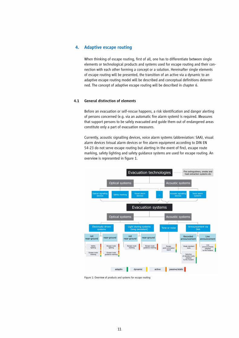
When thinking of escape routing, first of all, one has to differentiate between single elements or technological products and systems used for escape routing and their con-nection with each other forming a concept or a solution. Hereinafter single elements of escape routing will be presented, the transition of an active via a dynamic to an adaptive escape routing model will be described and conceptual definitions determi-ned. The concept of adaptive escape routing will be described in chapter 6.
General distinction of elements
Before an evacuation or self-rescue happens, a risk identification and danger alerting of persons concerned (e.g. via an automatic fire alarm system) is required. Measures that support persons to be safely evacuated and guide them out of endangered areas constitute only a part of evacuation measures.
Currently, acoustic signalling devices, voice alarm systems (abbreviation: SAA), visual alarm devices (visual alarm devices or fire alarm equipment according to DIN EN 54-23 do not serve escape routing but alerting in the event of fire), escape route marking, safety lighting and safety guidance systems are used for escape routing. An overview is represented in figure 1.
4.1
4. Adaptive escape routing
Figure 1: Overview of products and systems for escape routing
Evacuation technologies
Evacuation systems
Optical systems
Acoustic signalling devices
Visual alarm devices ...Safety markingOptical signalling
devices
Light storing systems (long persistent)
Announcement via SAA
Electrically driven systems
Recorded announcementnear-ground
passive/staticactivedynamicadaptiv
near-groundnot
near-ground
Safety lighting
Escape route marking
Escape route guidance marking
Escape point orientation
signal
Single standard texts
Live announcements
adapted to the incident
Selection of standard texts
adapted to the incident
Escape route lighting
Escape route guidance marking
Escape route marking
not near-ground
Live announcement
Tone or noise
Voice alarm systems
Fire extinguishers, smoke and heat extraction systems etc
Optical systems
Acoustic systems
Acoustic systems

12
Optical marking and signalling
Escape route markings guide to escape routes in their original form as signs. In this form they are still used today. They mark escape and evacuation routes; however, they do not react to the environment or to a hazardous event. They do not change their markings and are integrated as passive or static products into evacuation concepts. Next to markings, illuminated or backlit escape route markings in maintained mode or non-maintained mode are used. They are powered by an automatically starting power supply due to security purposes so that functionality is maintained or they can be activated in case of a power outage.
Optical signalling for escape routing has been realized since a few years for a safe evacuation in the event of fire. Therefore, usually luminaires positioned at ground level as well as escape sign luminaires are used which can indicate different escape directions. Escape route markings can therefore illustrate closed escape routes e.g. by showing red crosses. In case of an incident, signalling devices are activated, e.g. by a fire alarm system. Information on the hazard present is analysed. Conse-quently, based on these data, escape routes are determined and escape directions are shown by signalling devices.
As figure 2 shows, there is acoustic signalling next to optical signalling
4.2
Figure 2: Escape sign luminaires with variable direction indicator and blocking function (left), floor luminaires with direction indicator and chaser function (mid) and supplement acoustic signalling

13
Acoustic signalling
Acoustic signalling is used for alerting in case of a hazardous situation. Increasingly, loudspeaker announcements are used via voice alarm systems (SAA). They have advan-tages over simple acoustic signalling devices like horns or bells, e.g. they shorten the response time especially in buildings with locally unfamiliar visitors and hence, the necessary evacuation time (cf. EffGebEvMSyst, 1/2012).
Loudspeaker announcements of a speech alarm system can be used not only for inter-nal alerting but also for escape routing if the spoken text determines e.g. a building level direction “upstairs” or “downstairs”. The same applies for the call to contain-ment. In case of more complex, more variable announcements, currently, comprehen-sibility reaches its limits depending on spatial arrangements.
Moreover, escape route orientation signals with different impulse intervals and modu-lations are available for the acoustic signalling of escape route directions. Therefore, a single addressable loudspeaker system with cable surveillance and loudspeaker surveillance is used. For a time-adjustable usage of signalling devices individually addressable loudspeakers are needed.
By the use of speech alerting, persons inside the building can get situation-specific instructions like to close the windows for example or to avoid certain areas within a building.
Concepts for escape routing
There are different types of escape routing depending on concepts and elements that are used. First of all, there is static/ passive signalling or marking which are installed within a building and point to escape and emergency routes.
To support evacuation, optical and acoustic products are used that go beyond static signalling or marking. They are used in a way that they become active or are switched on only in case of demand like e.g. safety lighting (illuminated or backlit), electrically powered safety guidance systems or the playing of a recorded announcement by a speech alarm system. Such products enable to react to hazardous situations whereas they do not allow a change with regard to their status display. Dynamic escape routing builds upon this, but also goes beyond the system. It allows a one-off variable direction marking at the beginning of an evacuation (e.g. markings point upstairs/ downstairs, to the right/left or routes are approved/closed).
4.3
4.4

14
Figure 3 shows the functional principle of adaptive escape routing by illustrating the event of fire. With the help of the figure, it can be seen that available fire detectors, generally used for quick hazard identification, are not suitable for the surveillance of escape routes. Fire detectors usually installed on the ceiling as this is where they can most quickly identify smoke or gases. Escape route surveillance with regard to accessi-bility needs to be below 2.20 m where escaping persons are being.
Accessibility of escape routes can be limited by the hazard itself, e.g. in case of fire by smoke or toxic gases. Furthermore, accessibility depends also on current capacities. For example, congestions can occur as a consequence of an overuse by too many esca-ping persons, by local construction sites or inadmissible parking of items as well as by injured or panicky persons.
In order to assess the accessibility of escape routes, different technologies and pro-ducts can be integrated into a holistic concept (e.g. fire detector, escape route device, video cameras , (optical, acoustic, tactile) signalling devices, elevators, landlines and mobile phones, messengers, and building control systems. With the help of deter-mined information on the accessibility of escape routes signals pointing the way can be addressed and the most secure escape route can be displayed. The blocking and closing down of escape routes therefore is possible.
Examples for technical assessment of acces-sibility in case of fire are optical smoke density,
temperature and substance concentration of typical gases. In the event of an amok,
the location or movement patterns of the perpetrator can be surveyed by video images or
information of entrance control systems.
Figure 3: Possible functional principle of adaptive escape routing
Surveillance of escape and emergency routes’ accessibility
Fire alarm control panel
Layer of smoke
Fire detectors
e.g. Surveillance area
15
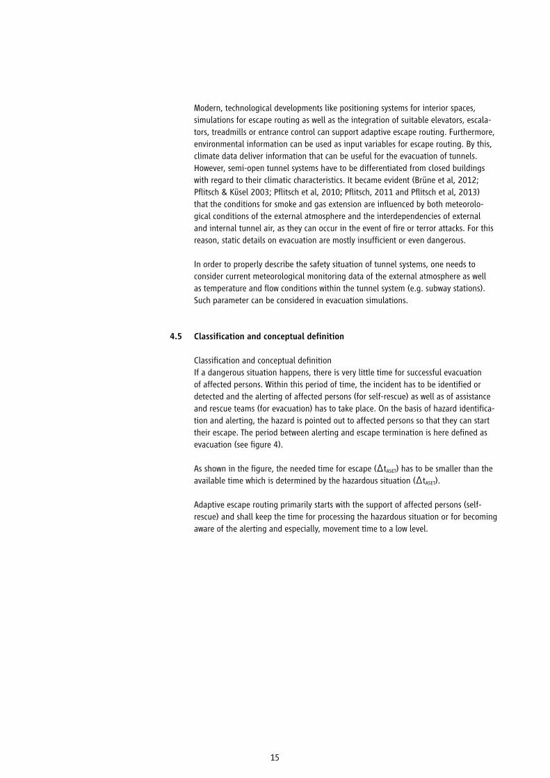
Modern, technological developments like positioning systems for interior spaces, simulations for escape routing as well as the integration of suitable elevators, escala-tors, treadmills or entrance control can support adaptive escape routing. Furthermore, environmental information can be used as input variables for escape routing. By this, climate data deliver information that can be useful for the evacuation of tunnels. However, semi-open tunnel systems have to be differentiated from closed buildings with regard to their climatic characteristics. It became evident (Brüne et al, 2012; Pflitsch & Küsel 2003; Pflitsch et al, 2010; Pflitsch, 2011 and Pflitsch et al, 2013) that the conditions for smoke and gas extension are influenced by both meteorolo-gical conditions of the external atmosphere and the interdependencies of external and internal tunnel air, as they can occur in the event of fire or terror attacks. For this reason, static details on evacuation are mostly insufficient or even dangerous.
In order to properly describe the safety situation of tunnel systems, one needs to consider current meteorological monitoring data of the external atmosphere as well as temperature and flow conditions within the tunnel system (e.g. subway stations). Such parameter can be considered in evacuation simulations.
Classification and conceptual definition
Classification and conceptual definition If a dangerous situation happens, there is very little time for successful evacuation of affected persons. Within this period of time, the incident has to be identified or detected and the alerting of affected persons (for self-rescue) as well as of assistance and rescue teams (for evacuation) has to take place. On the basis of hazard identifica-tion and alerting, the hazard is pointed out to affected persons so that they can start their escape. The period between alerting and escape termination is here defined as evacuation (see figure 4).
As shown in the figure, the needed time for escape (ΔtASET) has to be smaller than the available time which is determined by the hazardous situation (ΔtASET).
Adaptive escape routing primarily starts with the support of affected persons (self-rescue) and shall keep the time for processing the hazardous situation or for becoming aware of the alerting and especially, movement time to a low level.
4.5

16
Figure 4: Periods of time for evacuation (escape) (cf. Albrecht, 2011, p. 86)
Figure 5: Differentiation between concepts of escape routing (from passive/static via active and dynamic to adaptive systems)
The development of the hazardous situation over time and technological process im-plies a differentiation between today’s already used active and dynamic escape routing and adaptive escape routing which is described here.
The terms active and dynamic often are used synonymously. To a certain extent, these concepts are based on the same elements. Active concepts or systems are installed within a building and turned on in case of demand. They are becoming active. Dyna-mic concepts or systems are an advancement of active concepts. In case of demand, they are not only becoming active or are turned on, but they can further direct to different escape directions whereas the direction in case of an incident is defined once and remains until the end of evacuation. Adaptive concepts or systems represent a further stage of development. They are becoming active in case of demand, are able to point out different escape directions and can adapt to the development of a hazar-dous situation in contrast to active and dynamic systems. Hence, they can adjust the escape direction flexibly during evacuation. Therefore, adaptive concepts imply the surveillance of escape routes with regard to their accessibility. Figure 5 illustrates the differences between the diverse escape route concepts.
End of incidentBeginning of incident Detection
Detection
WarningAwareness
Movement
Identification
Inte
rpre
tatio
n
Act
ion
EscapeEvacuation
Alarm
End of Escape
Advancement

17
Definition 1: Active escape routing
Active escape routing describes the (partly automatic) support of escaping persons through technological measures targeting a safe evacuation with starting or acti-vating the signalling of escape routes in case of demand (e.g. ON/OFF).• The hazardous situation is pre-determined in location and time.• The (engineering systems’) technological measures are time-variably adjustable.• The signalling of escape routes is turned on from the beginning to the end of evacuation.
Definition 2: Dynamic escape routing
Dynamic escape routing describes the (partly automatic) support of escaping per-sons through technological measures targeting a safe evacuation whereas in case of demand, the signalling of escape routes is activated (e.g. ON/OFF) one-off variably (e.g. RIGHT/LEFT).• The hazardous situation is pre-determined in location and time.• The (engineering systems’) technological measures are time-variably adjustable.• The signalling of escape routes is one-off variably (pointing the way) adapted to the hazardous situation at the beginning of evacuation.
Definition 3: Adaptive escape routing
Adaptive escape routing describes the (fully automatic) support of escaping persons through technological measures targeting a safe evacuation whereas the signalling of escape routes is activated in case of demand (e.g. ON/OFF) and continuously variably (e.g. RIGHT/LEFT) adjusted.• The hazardous situation is pre-determined in location and time.• The (engineering systems’) technological measures are time-variably and direction-variably adjustable.• The signalling of escape routes is continuously adjusted (pointing the way) to the development of the hazardous situation from the beginning to the end of evacuation.• The surveillance of escape and emergency routes with regard to their hazard-free accessibility is essential
18
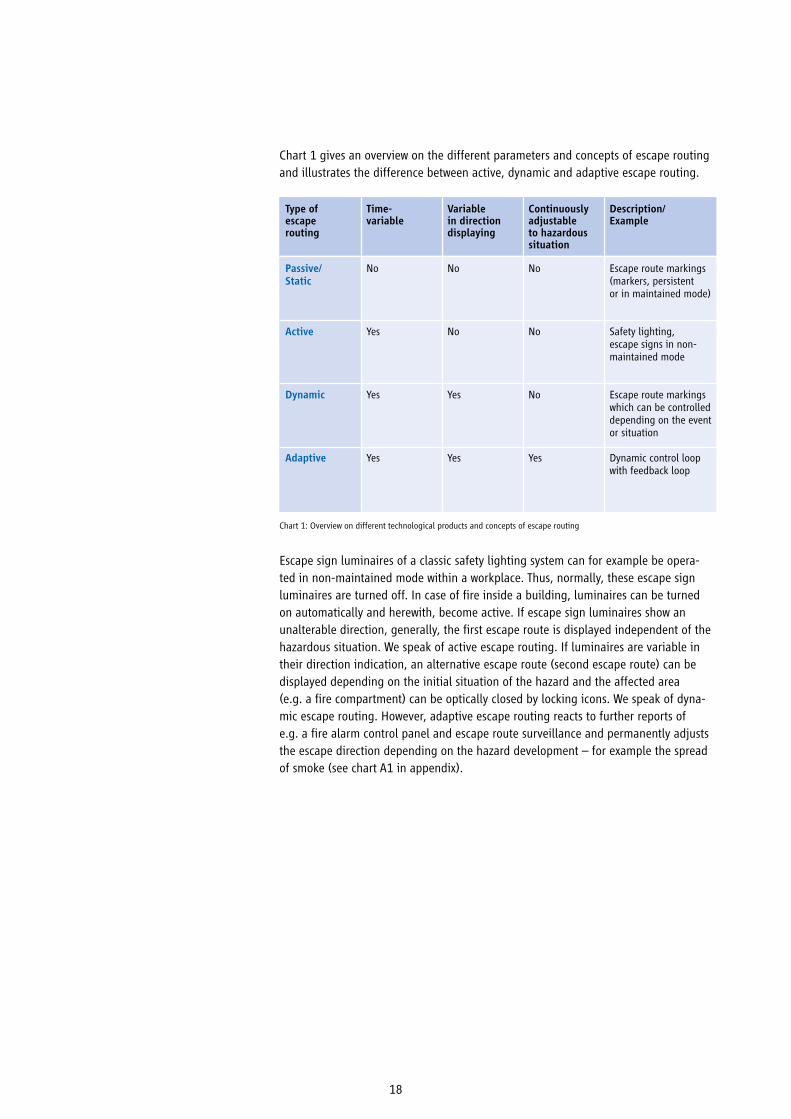
Chart 1 gives an overview on the different parameters and concepts of escape routing and illustrates the difference between active, dynamic and adaptive escape routing.
Type of escape routing
Time-variable
Variable in direction displaying
Continuously adjustable to hazardous situation
Description/Example
Passive/Static
Active
Dynamic
Adaptive
No
Yes
Yes
Yes
No
No
Yes
Yes
No
No
No
Yes
Escape route markings (markers, persistent or in maintained mode)
Safety lighting, escape signs in non-maintained mode
Escape route markings which can be controlled depending on the event or situation
Dynamic control loop with feedback loop
Chart 1: Overview on different technological products and concepts of escape routing
Escape sign luminaires of a classic safety lighting system can for example be opera-ted in non-maintained mode within a workplace. Thus, normally, these escape sign luminaires are turned off. In case of fire inside a building, luminaires can be turned on automatically and herewith, become active. If escape sign luminaires show an unalterable direction, generally, the first escape route is displayed independent of the hazardous situation. We speak of active escape routing. If luminaires are variable in their direction indication, an alternative escape route (second escape route) can be displayed depending on the initial situation of the hazard and the affected area (e.g. a fire compartment) can be optically closed by locking icons. We speak of dyna-mic escape routing. However, adaptive escape routing reacts to further reports of e.g. a fire alarm control panel and escape route surveillance and permanently adjusts the escape direction depending on the hazard development – for example the spread of smoke (see chart A1 in appendix).

19
Next to danger by fire hazards, numerous other types of dangers exist, like for example bomb threats, accidents including leakage and spills of dangerous substan-ces, natural hazards (e.g. earthquakes, flooding, storms) or the event of terror or amok. These dangers can be transferred into two possible reaction scenarios from a building evacuation point of view: the immediate escape out of a building or into safe building areas (see figure 6, left; e. g. in case of fire) or the locking down (see figure 6, right; e. g. in the event of amok). For further understanding the adaptive escape routing concept, the consideration of these two cases – triggering opposing reactions – is sufficient.
Possible combinations of hazardous situations like e. g. an assassin running amok causing one or multiple fires require opposed measures for human protection (escape vs locking down) whereby an automatic system may reach its limits. Prioritizing de-pends on specific circumstances of cases and therefore, cannot happen automatically. Regulations on details have to be undertaken within the framework of internal and external planning of hazards.
5. Risk scenarios
“Virtually any time, the emergence of a fire must be anticipated. The fact that no fire breaks out
for decades in many buildings does not prove that there is no danger existing but rather represents
a stroke of luck for affected persons which should be expected to end at any time.“
(Upper Administrative Court (OVG) Münster Judgement of 11.12.1987 AZ: 10A363/86;
since then established legal precedent)
Figure 6: Main scenarios of building evacuation
Escape into a safe locking down area Locking down
outside of the building
inside the building
Building evacuation

20
Figure 7: Time curve of fires (cf. Festag, Staimer & Münz, 09/2012, p. 6)
Example: Fire
In case of fire, only very short periods of time are available for building evacuation. Usually, after fire detection, less than ten minutes are available to alert persons in danger and to complete self-rescue (cf. EffGebEvMSyst, 2012). Within the building areas directly affected by fire, affected building users only have two to three minutes calculated from the start of alerting where they can leave a directly affected hazardous area without being harmed as figure 7 shows.
Initial fire
Tem
pera
ture
/C
Hyp
othe
tical
cou
rse
of d
amag
e
Fully developed fire
„Natural room fire“„Natural property fire“
Start of fireFlash-over
Time / t
Time / t
Fire fightingEscape
Warning Movement
Processing
Detection Alarm Rea
ctio
n
Self-rescue Rescue bythird parties
Identification Interpretation Action
Fire fighting(fire brigade)

21
Firstly, smoke and gases gather underneath ceilings for thermal reasons and from there on, spread over the place. Visibility is limited by smoke. Gases contain toxic substances (e.g. carbon monoxide, hydrocyanic acid) and substances that irritatemucous membranes (e.g. carbon dioxide) and which are harmful for human beings and affect their perception. Thereby, orientation of escaping persons is hindered. Besides the harmful effect on human beings, fire can impede available protection measures. For example, identification of references and emergency markings which may be installed high, but also illumination, can be significantly hampered. Furthermore, the display of escape routes can lead to its overuse under unfavourable conditions. On the other hand, some characteristic features of fire as e.g. visibility, temperature and concentration of substances can be used for detection, triggering of fire protection and fire-fighting measures as well as for surveillance of escape routes’ accessibility.
Example: Another hazardous situation
Another hazardous situation which requires immediate building evacuation can be imposed by a bomb threat. Although time is also a critical factor here, in contrast to the case of fire, this hazardous situation does not impede self-rescue in case the threatened action has not happened. Usually, all emergency exits are available and an adaptive routing is only required in case of an overuse of single escape routes.
As described in previous scenarios, certain hazardous situations do require the escape from directly affected areas but not the escaping out of the building. And there are types of hazards requiring the locking down of a place as long as no persons are directly within the hazardous area.
Characteristic for a hazardous situation requiring a lock down is for example the event of amok. In the event of an amok, it is key to keep the assassin, who usually planned the crime beforehand and disposes of local knowledge on the environment away from persons being inside the building and to hinder the assassin in his/her progressing and ideally, to isolate him/her in an empty part of the building. The detection of the hazard and essential assessment of the situation demand high requirements due to the high dynamic and brutality in such a situation (cf. Görtz, 27.01.2016). Only very short periods of time are available to warn persons who are inside a building and to move them to lock themselves down or to move into safe areas as well as to alert rescue teams (the alerting should be hidden from the perpetrator). Rescue teams need information to better assess the situation. Technological measures can support damage limitation at various points.

22
Present systems can be interconnected and used for an overarching hazard prevention and for the event of amok (see ZVEI 82010, 06/2011, p. 32). It has to be considered that with an overarching system, alerting and signalling of escape routes should be marked differently for different hazardous situations so that one can distinguish bet-ween the event of fire and the event of an amok. Furthermore, current discussions are about the question if automatic fire detection is to be suspended in the event of amok (and vice versa) in order to avoid opposing information. However, this prioritizing approach is not without difficulties.
Currently, with the development of VDE V 0827-1 “Emergency and danger response systems – Part 1: Basic requirements, duties, responsibilities and activities” and VDE V 0827-2 “Emergency and danger response systems – Part 2: Additional requirements for Emergency- and Hazard-Intercom“ two standards work on the planning, creation, commissioning, handover, operation and maintenance of a system as well as technical processes and responsibilities for the support of all processes from detection of an emergency to final procession.
Another hazardous situation which first of all requires the locking down of bystanders is expressed in an environmental alert. Included are for example dangers by hazardous substances which can penetrate a building from the outside. Although immediate action is required (closing of doors and windows), such a situation is not necessarily linked to an immediate escape.
In case of simultaneously happening dangerous hazards even sophisticated protection concepts can possibly reach their limits.

23
There are diverse requirements for escape routes that can vary in building planning according to building type and usage. Due to legal requirements for fire protection reasons for example, a safe area has to be reached in less than 35 meters via escape routes. Thereby, it is assumed that (according to building authorities):
• the shortest escape route is decisive,• the escape route is accessible in case of demand,• the situation does not change in case of demand,• building users behave according to plan even if becoming stressed.
In practice, this is not always the case. Beyond there are risks, especially with regard to liability duties from the duty to ensure public safety, that have to be considered as well (see chapter 3). Adaptive escape routing therefore can help to cover non-conside-red residual risks.
Safety enhancement
Contrary to static, active and dynamic escape routing, in the event of a hazardous situation, adaptive escape routing offers the advantage of changing the routing of affected persons according to the development of the hazardous situation. With fire development, escape routes and staircases that may have been safe, can become inaccessible in no time. In this case, escaping persons have to be rerouted to alter-native escape routes or staircases and diverted around newly developed hazardous areas [Diversion].
With a facilitated orientation which is enabled for building users by adaptive escape routing, a secure and reliable self-rescue out of the hazardous area is targeted [Rou-ting out].
Gaining time
Adaptive escape routing happens automatically. Hence, persons can quickly be routed out of the hazardous area. With the help of clear optical and/ or acoustic support for orientation during escape, time is gained for self-rescue of affected persons.
Reference: In case of demand, a manual control of adaptive escape routing by the rescue team should be possible at any time.
Adaptive escape routing can reduce the duration of evacuation if groups of persons can be routed via safe escape routes and if congestions as well as aberrations can be avoided.
When routing out of a building, a higher walking speed can be reached by measures for adaptive escape routing which help avoiding stagnations and delays at suddenly occurring hazardous areas.
6. Benefits of adaptive escape routing
6.1
6.2
Adaptive escape routing can lead to a gain in safety although the duration
of evacuation may be higher due to a longer – but more safe – escape route
Over all, by supporting self-rescue, evacuation can be
completed more quickly.

24
Utilization of escape routes adapted to the situation
On the one hand, escape routes can be blocked by the source of danger and on the other hand, they can be overused by persons. With adaptive escape routing, the capa-city of escape routes can be adapted to the situation by considering the accessibility of escape routes at the time of signalling.
Example: Shopping mall
In a shopping mall, health-harming gases are released due to a technical defect in a supermarket area. With the help of targeted escape routing and it being adjusted to the situation, persons can be routed out of the hazardous area without the forma-tion of bottlenecks on the way and overuse of assembly points. Often, well-known routes and main routes are used for escape which may result in overuse. Bottlenecks like exits, staircases or doors are areas that are prone to congestion where panicky behaviour can occur. Furthermore, in case of overuse, assembly points are extended to streets and a further danger for persons is revealed by traffic. Moreover, persons that are within a shopping arcade on their way to the supermarket, can be routed to safe areas in time.
6.3

25
Avoidance of panicky behaviour
There are different types of panic – which are seldom – and there is panicky behaviour – which happens more often (cf. Ungerer & Morgenroth, 1999, p. 79).When speaking of panic, an affected person’s behaviour is without self-control or control of third parties. It occurs, „if there is a danger and it avoidance cannot be guaranteed nor by an individual nor by a collective group anymore“ (Ungerer & Mor-genroth, 2001, p. 51). „Psycho-vegetative, emotional and informative control loops “ do not obey „standardizations of survival strategies “ (Ungerer & Morgenroth, 2001, p. 50). These processes are not as extremely escalated as it is the case for panic when seeking of panicky behaviour. Through adaptive escape routing part of external control is taken care of. Thereby, panicky behaviour shall be reduced. It has to be considered that personality as well as social and cultural environment influence human beings’ behaviour. Schneider & Kirchberger (2007) refer to studies and follow the facilitated classification of human behaviour patterns in case of fire with regard to the following three groups (cf. also Leach, 2004):
Group 1: Human beings react very rational to incidents. There are no indications for emerging hectic rush and the overview is maintained. With their clear acting these persons usually have the role of important leadership functions during evacuation or eviction.
Group 2: Human beings (the majority) are stunned by the occurring situation but are rather calm. After the first shock phase they react with active behaviour, usually with assistance. This group can be positively influenced by clear instructions, e.g. by adaptive escape routing with its optical and acoustic indications. Reaction times are shortened and the evacuation accelerated.
Group 3: Human beings react unpredictable in critical situations, mainly with solidi-fication, panic or flight. Panic is usually revealed by useless action, disorientation and loss of reality.
6.4
26
Emergency rescue service
If for example a reduction of walking speed on an escape route is detected, but also present persons identified, this points to an incident that possibly needs further support. Hence, persons could fall or not be able to rescue themselves due to acute health problems and need further help.
According to general building requirements and its usage, the area at direct fire risk should be always empty and persons in direct danger should have moved to a safe area before the arrival of the fire brigade. Single Federal State building regulations require further fire protection arrangements for structural installations and rooms of a special type or usage which usually are then key to the respective fire protection concept. Such fire protection concepts should regularly contain a chapter on „organizational fire protection“ with statements on evacuation. In business areas, the workplace regulation (ASR 2.2) which is established for the realization of the Occupati-on Health and Safety Act [Arbeitsschutzgesetz] (ArbSchG) and the workplace regulation [Arbeitsstättenverordnung] (ArbStättV) require the determination of fire protection assistants. Next to first firefighting of a developing fire, the fire protection assistant has to initiate a fast evacuation of his/her area of responsibility in the event of a hazard and help persons that are unfamiliar to the location or limited in their mobili-ty. Adaptive escape routing can reduce the group of persons that need organizational support for evacuation. Available assistants can focus on those persons that are not able to rescue themselves like for example injured ones.
6.5

27
Consideration of particular groups via the 2-senses principle
The 2-senses principle (also referred to as two-channel principle) forms the basis of barrier-free creation of public buildings or assembly areas/ accommodations. In these buildings, one cannot expect a building-specific knowledge of the persons inside the building. With the consideration of the two-senses principle, the chance for self-rescue shall be improved for building users with sensory limitations.
The standardizations DIN 18040 part 1 (“Construction of accessible buildings: Publicly accessible buildings“) and part 2 (“Construction of accessible buildings: Dwellings“) are introduced in all countries as “Technical Building Regulations“ by building autho-rities. However, in many countries with special requirements or deviations (an overview on the references of the respective countries’ current announcements of introduced technical building regulations is published regularly by the German Institute for Cons-truction Technology, DIBt).
According to the two-senses principle information is simultaneously accessible for two of the three human senses – seeing, haring, touching:
• instead of seeing: hearing and touching/ feeling• instead of hearing: seeing and touching/ feeling
According to the two-senses principle, the initiation of the alert and escape routing are triggered by at least two ways. Which senses are addresses depends on the specific situation whereas optical and acoustic solutions currently dominate. Thus, the Model Ordinance Governing Accommodation Establishments (MBeVO, 2014) states in §9 (1) that […] „the initiation of the alert has to be clear and identifiable optically and acoustically“.
85 percent of information is usually digested via „seeing“, about 10 percent via „hearing“, the rest via „touching/feeling“ (cf. Rau, 2011, p. 37 ff. in Harder, 2012, p. 26). Also for human beings without disabilities, the two-senses principle is a facilitator and already today, it is used in daily life, e. g. mobile phones (ringing tone and at the same time vibration alert) or pedestrian traffic lights (red/green signal and acoustic tone).
The inclusion of the two-senses principle offers further advantages for adaptive escape routing:• Increase in safety for specific groups of persons• Easier orientation also for persons without disabilities• Barrier-free usage of buildings, facilities and assembly points• Reduced effort needed for organizational measures• Quick evacuation of the building even without building specific knowledge
6.6
To a certain group of persons, special attention is to be given in the alerting and evacuation concept.
Included are elderly, children as well as groups of persons with motoric or sensory
limitations in particular.
28
6.8
Probability of default and flexibility
As experience shows, failure or probability of default of building and systems enginee-ring measures are low provided their construction being conform to standardization, operation and respective maintenance. This is difficult to guarantee for organizational measures as they depend on the presence and correct reaction of certain persons at an essential point of time.
Building measures have the advantage that they are constantly present but at the same time they have the disadvantage of being rigid and inflexible. The adaptation to new allocations of surfaces and the reutilization of rooms often is only possible after expensive and long-lasting reconstruction measures. Systems engineering measures also are constantly present and have a high reliability due to many requirements and tests. However, they have the advantage of being relatively easy, fast and therefore cost-effectively adaptable – as one rarely has to engage in the building substance.
Compensations
Often, building measures being standard requirements in statutory building regula-tions can be compensated by systems engineering solutions. This is true especially for reconstructions and renovations of existing stock, in particular of listed buildings where subsequent building solutions according to the requirements of today’s building regulation often are not realizable.
Example: Renovation of historic buildings
Statutory building regulations for fire protection requirements are only very difficult to meet or are not feasible in case of the renovation of historical buildings. While maintaining the singularity of these building, solutions have to be found which are compatible with today’s fire protection requirements and historic preservation. Often, statutory building regulations cannot literally be fulfilled due to special requirements of historic preservation. In these cases, compensation measures have to be found in order to reach the protection target of a safe self-rescue of persons. Therefore, systems engineering fire protection measures are suitable due to their flexibility.
When it comes to new constructions and changes of use, developers, architects and specialist planners are limited in their creativity by legal requirements. Architectonic interests of a building like transparency, functionality and aesthetics shall be con-sidered for construction which is often only possible to a certain extent due to strict implementation of legal regulations. Via a compensation by systems engineering mea-sures, a realization of the building draft can be reached (cf. EffGebEvMSyst, 2012).
6.7
29
Economic efficiency
The protection of health and human life has priority and is seldom too expensive for legal reasons. Considering economic efficiency, the degree of target reaching of mea-sures is becoming dependent on the effort required. Legally speaking, it is imperative to bring evidence that the legally determined protection targets are achieved in the event of an emergency. It is legally irrelevant by which measures and methodologies the protection objectives are ensured. This often is taken care of by protection con-cepts, an expert report or a specialist planning of a specialized or maybe even a state-approved engineer.
In order to reach protection objectives, constructional, systems engineering and organizational measures are available and are interconnected with each other. What may not be possible by one way or may be too expensive, can be realized by another way. Only with the interaction of measures from all three areas, the reaching of fire protection targets can be ensured.
Even if flexible modification of a building for its change of use over the entire period of building operation may not be of special interest for the developer/ operator, the integration of systems engineering technology will be economically efficient, not least when looking at liability risks, in case risks can be covered by systems engineering that are not considered by the building regulation’s requirements. Liability risks of a developer/ operator against building users, passers-by, neighbours etc. can arise from a potential infringement of protection laws (§ 823 Abp. 2 BGB) on the one hand and from the infringement of the duty to ensure public safety (§ 823 Abp. 1 BGB) on the other hand. Protection from such liability risks is never part of general building autho-rities’ inspection, approvals and requirements as the building regulation does not aim to protect the developer from liability but the public from the developer. The building regulation however, does not hinder a developer either to seize measures for his/her own protection from utilization of liability suits. However, this issue is left exclusively to the developer’s or building operator’s own considerations and decisions.
6.9
“Economic efficiency” of fire protection measures plays a minor role from a building regulations point
of view as well as from a liability point of view.
In order to reach protection objectives constructional, systems engineering and organizational
measures – being equivalent – are available.

30
Static or passive elements of escape routing are always in an identical state inde-pendent of the event of a hazard. Examples are markings or illuminated or backlit escape route markings in maintained mode. In active escape routing, elements for escape routing are turned on in case of demand. The direction display is not variable. Dynamic escape routing goes beyond and reacts to the hazardous situation at the beginning of evacuation and respectively variably sets orientation signals. Orientation signals are not continuously adapted to the hazard’s development and there is no surveillance of escape routes for accessibility reasons.
7. The concept of adaptive escape routing
Figure 8: Schematic building sketch with passive escape route marking (e.g. non-illuminated pictograms)
Figure 9: Passive escape route marking does not react to a hazard

31
Figure 8 shows a schematic building sketch. The illustrated floor is spatially divided into four segments. Marking is realized by passive elements. As figure 9 shows, passive elements do not react to a hazard. In figure 10, using active escape routing, signal-ling devices pointing to the escape route are turned on independent of a hazardous situation in case of a hazard. Included are for example escape route markings in non-maintained mode and recorded announcements of a speech alarm system. Furthermore, a near-ground safety guidance system can be included which is shown in figure 11 as floor marking.
Figure 10: Schematic building sketch with active escape routing (active escape sign luminaires as well as voice alarms) independent of the hazardous situation
Figure 11: Schematic building sketch with active escape routing (active escape sign luminaires and near-ground guidance markings as well as voice alarms) independent of the hazardous situation
32
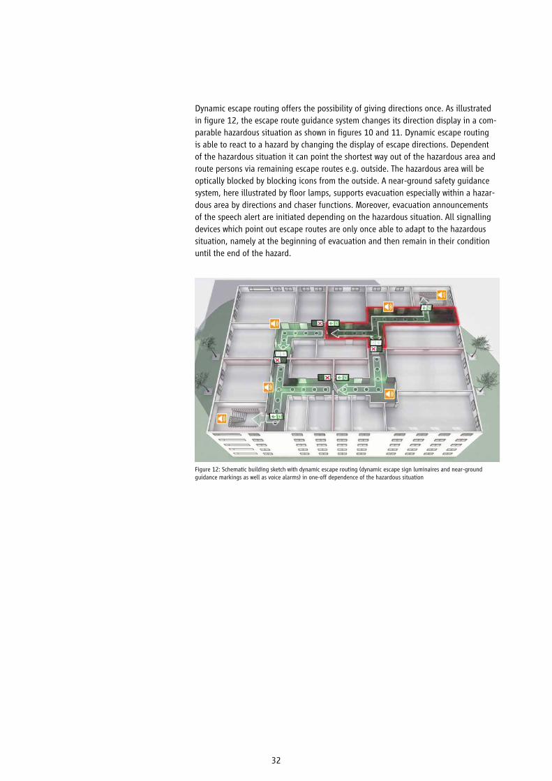
Dynamic escape routing offers the possibility of giving directions once. As illustrated in figure 12, the escape route guidance system changes its direction display in a com-parable hazardous situation as shown in figures 10 and 11. Dynamic escape routing is able to react to a hazard by changing the display of escape directions. Dependent of the hazardous situation it can point the shortest way out of the hazardous area and route persons via remaining escape routes e.g. outside. The hazardous area will be optically blocked by blocking icons from the outside. A near-ground safety guidance system, here illustrated by floor lamps, supports evacuation especially within a hazar-dous area by directions and chaser functions. Moreover, evacuation announcements of the speech alert are initiated depending on the hazardous situation. All signalling devices which point out escape routes are only once able to adapt to the hazardous situation, namely at the beginning of evacuation and then remain in their condition until the end of the hazard.
Figure 12: Schematic building sketch with dynamic escape routing (dynamic escape sign luminaires and near-ground guidance markings as well as voice alarms) in one-off dependence of the hazardous situation

33
Using dynamic escape routing makes sense if the building room considered is a closed area, e.g. a fire compartment, and the spreading of the hazard beyond this area can be excluded at least for a defined period of time, e.g. 90 minutes.
Adaptive escape routing offers the possibility to re-route escaping persons based on a continuous surveillance of escape routes and considering a possible change of the hazardous situation, i.e. it permanently follows the hazard’s development. Both, hazard detection as well as escape routing signals in such a system have to react to temporal changes and react depending on the hazardous situation. Figure 13 illustrates the beginning of the hazardous situation. Optical and acoustic signalling devices close the affected area. Figure 14 shows that the hazard has spread to another building segment (downstairs). Both, speech alert and optical elements of the adaptive escape routing react to this hazardous situation.
Figure 13: Schematic building sketch with adaptive escape routing (adaptive escape sign luminaires and near-ground guidance markings as well as voice alarms) depending on the hazardous situation (point in time t1)
Figure 14: Schematic building sketch with adaptive escape routing depending on the hazardous situation (point in time t2; the hazardous situation changed)

34
If systems are adaptive or dynamic, generally depends on the conceptual integrati-on of its elements including the surveillance of escape route accessibility and is not dependent of the single products and systems themselves. Signs for escape route marking are passive whereas backlit markings and general evacuation announcements of a speech alarm system which are turned on in the event of a hazard are classified as active. In case of a one-off adaptation of the escape direction to a hazardous situation (e.g. right/left, up/down, approval/closing), it is classified as dynamic. If the signalling of escape routes is permanently adapted to environmental conditions according to the hazard’s development, it is determined to be adaptive. This is true for optical guidance systems as well as for loudspeaker announcements of a speech alerting or tactile systems.
In adaptive escape routing, escape routes are permanently monitored to prove their accessibility. The adaptive system recognizes if an escape route is not accessible any more (e.g. smoke, gases, obstacles) and automatically reroutes the security guidance system by optical and acoustic display of safe escape routes.
Interaction of optical and acoustic signalling
The core of adaptive escape routing is the control of escape route signalling through constant assessing of the hazardous situation. Incoming information on hazards (e.g. fire detectors) is continuously evaluated by a central fire alarm system and passed on to signalling devices and further measures if necessary. At the same time, information on the accessibility of escape and evacuation routes (e.g. escape route detectors) are analysed and included into the evaluation.
In adaptive escape routing, the existing system including different elements is key which enables
a continuous adjustment of signalling escape routes to the hazard’s development

35
Already today, systems for escape routing are used in numerous properties. Currently, however, there is no constant surveillance of escape routes’ accessibility. The following examples shall give impetuses for cases where escape routing is useful. The examples mentioned here partly draw on fire protection concepts of the respective properties.
Example: New construction of a medical centre
Architectonical interests of a clinical building shall be realized in the same way as open designs. Not all staircases are connected to a direct exit to the outside and are accessed by corridor sections that are maximum 10 m long. Staircases do not dispose of a fume protection pressure device.
CompensationTwo evacuation levels are planned by which escaping persons can be safely routed to the outside with the help of a comprehensive escape route guidance system (com-prising of dynamic safety escape sign luminaire and recessed floor luminaires with chaser function). In case one of the two evacuation levels is filled with smoke, persons are routed respectively into the other smoke-free level with the help of the dynamic escape route guidance system. Automation and control is triggered by a (comprehen-sive) fire alarm system.
On the left side, figure 15 shows a situation within a clinic where the escape route guides through a staircase. The staircase’s entrance is optically closed by a red cross with flashing function. Within the right figure, floor luminaires with direction displays and chaser function as well as dynamic escape sign luminaires within the course of the corridor can be seen.
8. Application examples of escape routing
Figure 15: Staircase entrance (left) and corridor situation in a medical centre (right)

36
Example: Renovation of a listed town hall
This example describes the renovation of a listed town hall. There is an open connec-tion between the entrance area on the ground floor and the third floor. Between the first and the second floor as well as between the second and the third floor a compart-mentalization is planned. This constructional separation is arranged on the intermedi-ate landings in the course of the stairs. Between the ground floor and the first floor there is no constructional separation between the floors implemented because these areas are listed. Furthermore, the corridor of the “central area” within the first floor (see figure 16) has a length of more than 30 m without the formation of smoke con-trol sections.
CompensationCompensatory measures have to be implemented which particularly have to ensure the protection objective of the persons’ self-rescue. Due to the open connection between ground floor and first floor, the danger of smoke generation exists within the first floor in the event of a fire originating from the ground floor.In order to nevertheless ensure a self-rescue of persons that are within the halls of the first floor, escape routing by backlit markings is installed to route persons to the out-side and around potential sources of danger.
Figure 16: Listed central area within the first floor with open staircase area to the ground floor

37
In the event of smoke generation in the central area, hall users or users of the library are routed through connecting doors of the halls and adjacent offices to the east wing of the building which is separated from the central area from a fire protection point of view. Then, they are further routed via external stairs to the outside (see figure 17). The halls’ accesses to the central area are optically closed by a flashing, red cross.
Figure 17: Sketch of first floor with central area, halls and offices with illustrated dynamic escape sign luminaires
Building element east, first floor
Council hall
Central area
Courtyard
East wing
West wing
Building element
west
Dynamic safety markingluminaire
HallLibrary
Hall Hall
Office
Office
Office

38
Example: Tunnel
In a town, the construction of a pedestrian tunnel is planned including an elevator as access to a castle. The entrance building with the subsequent tunnel is accessed by a public traffic area. The tunnel is a gallery of a length of about 100 m. Visitors can reach the castle via an elevator located at the end of the tunnel.
In normal operation, the tunnel can be accessed by an upstream entrance building. In order to establish an escape route out of the tunnel and access routes for the fire brigade independent of the entrance building (see figure 18) a bypass was planned which is arranged between the entrance building and the tunnel and which immedia-tely leads to the outside. With a length of about 100 m, the tunnel exceeds the length of an escape route allowed by the building regulation which is determined to be no more than 35 m. Furthermore, the building does not have a second escape route.
Figure 18: Floor plan of the entrance building on the ground floor
Fire protection sliding gate
Beginning of tunnel
Entrance
Bypass

39
CompensationIn order to compensate these deviations, the tunnel inter alia has been provided with fire compartments, the elevator designed as fire brigade elevator and dynamic escape routing was used.
In case the fire protection sliding gate is closed at the beginning of the tunnel, persons are routed via the bypass to the outside with the help of the dynamic escape route guidance system.
In figure 19, the fire protection sliding gate and the bypass exit can be found on the left side. The tunnel is divided by two fire compartments into three sections and is isolated from the elevator vestibule by a lock. The fire brigade elevator enables the entering of the fire brigade into the tunnel in the event of a hazard. In order to ensure the fire brigade elevator’s functionality, a smoke protection pressure device was provided for the elevator shaft and its vestibule. Dynamic escape routing consists of dynamic safety escape sign luminaires installed high and dynamic direction arrows installed low. Signalling devices indicate the escape route to be used whereas the attention is increased by a flashing function. The automation and control of the dyna-mic escape routing is triggered by a (comprehensively installed) fire alarm system.
Figure 19: Floor plan of the tunnel
Bypass
Fire protection sliding gate
Fire protection doors
Elevator vestibule
Lock with fire protection doors
comprehensive
40
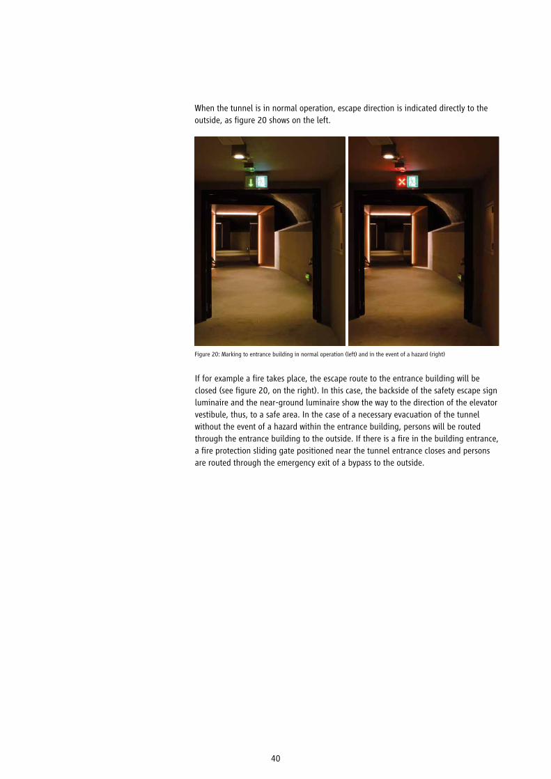
When the tunnel is in normal operation, escape direction is indicated directly to the outside, as figure 20 shows on the left.
Figure 20: Marking to entrance building in normal operation (left) and in the event of a hazard (right)
If for example a fire takes place, the escape route to the entrance building will be closed (see figure 20, on the right). In this case, the backside of the safety escape sign luminaire and the near-ground luminaire show the way to the direction of the elevator vestibule, thus, to a safe area. In the case of a necessary evacuation of the tunnel without the event of a hazard within the entrance building, persons will be routed through the entrance building to the outside. If there is a fire in the building entrance, a fire protection sliding gate positioned near the tunnel entrance closes and persons are routed through the emergency exit of a bypass to the outside.

41
In case of fire within one of the three fire compartments of the tunnel, persons are routed out of the affected area using the shortest way, both, via the entrance building or the bypass to the outside and also through the lock into the elevator vestibule. The elevator vestibule (see Figure 21) represents a safe area due to the separation from the tunnel according to fire protection standards and smoke protection pressure de-vices. Persons who have been routed to this area by dynamic escape routing can wait here for the fire brigade to be rescued via the elevator.
Usually, the escape route through the tunnel in the direction of the entrance building is displayed in normal operation. In the event of a fire within the tunnel, doors close automatically and the escape route through the tunnel is optically blocked.
Figure 21: Elevator vestibule with lock

42
Example: Interchange station of subways
In spacious, complex building structures like subway stations fire protection require-ments with regard to keeping escape routes smoke-free during self-rescue are often difficult to achieve. Major challenges to the achievement of fire protection are addres-sed by long and unclear escape routes and a large number of potentially affected persons. One has to expect up to 4000 persons being in an interchange station (cf. EBA-formula by the German Federal Railway Authority [Eisenbahn-Bundesamt] 2011, p. 10f.). Moreover, escape routes from a train platform to the outside usually cover a length of 100-200m. In order to be able to react to these conditions, infor-mation is needed that is adapted to the situation.
The research project „OrGaMIR“(cf. Koch & Plaß, 2009) integrated variable environ-mental information of a subway station into its evacuation (Figure 22 shows an escala-tor filled with smoke inside the subway station). Therefore, the interchange station was provided with wind sensors and devices for the identification of hazardous substances and thus obtained information is transmitted to an IT-system for analyzation and visualization.
It has been shown that the accessibility of escape routes depends on environmental conditions. Based on the same spatial conditions, an escape route’s accessibility can quickly change depending on wind direction and direction of flow.
Figure 22: Escalator inside a subway station filled with smoke

43
With the help of environmental information, not only the spreading of a hazard can be identified but the location of the hazard’s emergence can be determined via measured concentration of toxic substances. This again can be used for assessing further deve-lopment of the hazard and derivation of measures. Environmental information can be integrated into simulations. Figure 23 shows an exemplary extract, where all secure or fast escape routes are shown to the control centre employees in a 2D-view of the sub-way station. In order to display the optimal escape routes for single sections, chasing lights have been integrated inside the station. Activation of dynamic escape routing is carried out by responsible persons determined by the subway operator visually who are reviewing the situation with the help of video connection.
From the report of a sensor for hazardous substances to the activation of chasing lights and thus to the targeted dynamic escape routing via accessible areas to the out-side, the IT-system needs about 15 seconds for calculation and processing.
The entire system’s functionality consisting of sensor technology, calculation and orga-nizational integration has been verified in a field test during running subway opera-tion. After the release of odour- and colourless test gases, the system identified the substance and properly predicted hazard spreading as well as safe escape routes and activated escape routing.
Figure 23: Control centre view of dynamic routing
44
Adaptive escape routing is an advancement of active and dynamic escape routing. The concept aims to enable the determination of a safe escape route also conside-ring a hazard’s development. Therefore, the surveillance of escape and emergency routes’ accessibility is essential. Adaptive escape routing emerged from the field of fire protection. However, it is possible to realize overarching concepts that also consider further hazards.
For further pursuing the concept of adaptive escape routing in the future, the follow-ing fields of action have to be worked on:
First of all, (further) development of products and systems is needed that allow adap-tive use. Such products already exist to a certain extent (optical, acoustic and tactile products). Action is needed especially for certified products and systems for the sur-veillance of escape and emergency routes’ accessibility.
A fire alarm system could be used as a control device for adaptive escape routing by using the respective products. A number of possible scenarios reveals a big challenge due to complexity.
For security products, which are being addressed here, determinations and standards are needed in order to guarantee high reliability of elements and entire systems. Due to this reason, at the same time, the development of standards which define rules for product requirements (product standards) but also specify requirements regarding their application (application standards) is essential next to the development of tech-nological products.
Moreover, research activities are required which ensure the interaction of different elements to a functional system resulting in adaptive escape routing. Required research projects also need to focus on the measure’s effectiveness besides techno-logical functionality. Therefore, empirical studies from the monitoring of examples inter alia are useful. Diverse influential factors on persons’ behaviour in the event of a dangerous hazard also have to be analysed and how their escape can be suppor-ted effectively and adaptively.
Furthermore, it is important to inform architects, planners, operators, authorities and fire brigades who are involved in planning, construction and approval of evacuation concepts about possibilities and chances of adaptive escape routing so that it can be applied and receive acceptance within the market.
9. Future advancement and need for action

45
List of references
Albrecht, C. (09/2011). Grundlagen und Sicherheitskonzept für den Nachweis der Entfluchtung im Brandfall [Basics and security concept for the certificate of evacuation in the event of fire]. Dietmar Hosser (Ed.): 25. Fachtagung Brandschutz – Forschung und Praxis. Braunschweiger Brand-schutz-Tage 2011, Braunschweig 27.-28.09.2011, p. 83 - 100.
AnEffGebEvMSyst (8/2011). Anlage zur Broschüre „Effektive Gebäudeevakuierung mit System: Techni-sche Maßnahmen im Brandfall und bei sonstigen Gefahrenlagen“ [Appendix to brochure “Systematic Effective Building Evacuation: Technical measures in the event of fire and in case of further hazardous situations”]. ZVEI – German Electrical and Electronic Manufacturers’ Association, Safety/ Security and Defence Division, Frankfurt am Main.
ArbSchG (1996). Arbeitsschutzgesetz – Gesetz über die Durchführung von Maßnahmen des Arbeits-schutzes zur Verbesserung der Sicherheit und des Gesundheitsschutzes der Beschäftigten bei der Arbeit [Working Conditions Act – law on the implementation of measures under the Working Condi-tions Act for security and health protection improvement of employees during work].
ASR 2.2 (2012). Maßnahmen gegen Brände. Technische Regeln für Arbeitsstätten [Measures against fires. Technical guidelines for working places], Ausschuss für Arbeitsstätten (ASTA). BAuA.
ASR 2.3 (2014). Fluchtwege und Notausgänge, Flucht-und Rettungsplan. Technische Regeln für Arbeitsstätten [Escape routes and emergency exits, escape and emergency plan. Technical guidelines for working places], Ausschuss für Arbeitsstätten (ASTA). BAuA.
ASR V3a.2 (2012). Barrierefreie Gestaltung von Arbeitsstätten. Technische Regeln für Arbeitsstätten [Barrier-free design of working places. Technical guidelines for working places], Ausschuss für Arbeits-stätten (ASTA). BAuA.
BGG (2002). Gesetz zur Gleichstellung behinderter Menschen (Behindertengleichstellungsgesetz) [Act on the Equal Treatment of Disabled People] of 27th April 2002 (BGBl. I p. 1467, 1468), which recently was changed by article 12 of the respective law of 19th December 2007 (BGBl. I P. 3024).
BGH, Judgement of 11.10.1990, VII ZR 120/89, NJW 1991, p. 562 f.
Brüne, M., Pflitsch, A., Agnew, B., Spiegel, J. (2012). Dynamics of natural air flow inside subway tunnels. In: Proceedings from the fifth International Symposium on Tunnel Safety and Security, New York. 14 - 16 March 2012.SP Technical Research Institute of Sweden, Borås, Sweden, 329-337.
Deutsches Wörterbuch (1983). Deutsches Wörterbuch von Jacob Grimm und Wilhelm Grimm [German dictionary by Jacob Grimm and Wilhelm Grimm]. 1. Band, Leipzig: p. Hirzel Verlag.
DIN 18040-1 (2010). Barrierefreies Bauen - Planungsgrundlagen. Teil 1: Öffentlich zugängliche Gebäude [Construction of accessible buildings - Design principles. Part 1: Publicly accessible buil-dings]. Deutsches Institut für Normung e.V., Berlin: Beuth.
DIN 18040-2 (2011). Barrierefreies Bauen - Planungsgrundlagen. Teil 2: Wohnungen [Construction of accessible buildings - Design principles. Part 1: Dwellings]. Deutsches Institut für Normung e.V., Berlin: Beuth.
Drodowksi, G. et al. (1989). Duden: Etymologie – Herkunftswörterbuch der deutschen Sprache [Etymology – Etymological dictionary of the German language]. Mannheim: Dudenverlag.
EffGebEvMSyst (1/2012). Effektive Gebäudeevakuierung mit System: Technische Maßnahmen im Brandfall und bei sonstigen Gefahrenlagen [Systematic Effective Building Evacuation: Technical measures in the event of fire and in case of further hazardous situations]. ZVEI – German Electrical and Electronic Manufacturers’ Association, Safety/ Security and Defence Division, Frankfurt am Main.
Eisenbahn-Bundesamt (2011): Leitfaden für den Brandschutz in Personenverkehrsanlagen der Eisenbahnen des Bundes [Guideline for fire protection within passenger transport systems of federal railways]. Referat 21. Status: 01.03.2011.
Famers, G. & Messerer, J. (2008). „Rettung von Personen“ und „wirksame Löscharbeiten“ – bauord-nungsrechtliche Schutzziele mit Blick auf die Entrauchung. Ein Grundsatzpapier der Fachkommission Bauaufsicht [“Rescuing of persons” and “effective fire-fighting operations” – protection objectives according to building authorities with regard to smoke extraction. A policy paper by by the Building Control Committee].

46
Festag, P. & Herbster, H. (2012). Anlagentechnische Beiträge zur Unterstützung der Evakuierung von Gebäuden im Brandfall [Systems engineering contribution to support evacuation of building in the event of fire]. Dietmar Hosser (Ed): 26. Fachtagung Brandschutz – Forschung und Praxis. Braunschweiger Brandschutz-Tage 2012, Braunschweig 19.- 20.09.2012, p. 41- 60.
GG (2014). Grundgesetz für die Bundesrepublik Deutschland [German Constitutional Law] published in the corrected version in part III of the Federal Law Gazette, outline number 100 – 1, recently chan-ged in article 1 of the law on 23rd December 2014.
Görtz, R. (27.01.2016). Räumen oder Verbleiben? Amokschutz und Brandschutz – konkurrierende Schutzziele? [Evacuate or remain? Amok protection and fire protection – two competitive protection objective?] Presentation at ZVEI – German Electrical and Electronic Manufacturers’ Association, Safety/ Security and Defence Division, Frankfurt am Main.
Harder, J. (2012). Mit anderen Augen sehen [Seeing with different eyes]. Bachelor thesis, Course of study: Urban planning, HafenCity Universität Hamburg.
Koch, R. & Plaß, M. (2009): Optimising Rescue Operations in Subways: the OrGaMIR Project (Organi-sationsübergreifende Gefahrenabwehr zum Schutz von Menschen und kritischen Infrastrukturen durch optimierte Prävention und Reaktion). In: Peter Elsner (Ed.): Future Security. 4th Security Research Conference Karlsruhe. Fraunhofer-Verbund Verteidigungs- und Sicherheitsforschung VVP. Stuttgart: Fraunhofer Verlag,p. 11-16.
Leach, J. (2004): Why People ‘Freeze’ in an Emergency:Temporal and Cognitive Constraints on Survival Responses, Aviat Space Environ Med, 75:539-42.
Mark, R. (1/2001). Das Fluchtverhalten von Menschen in Extremsituationen [Escape behaviour of human beings in extreme situations]. Brandverhütung 1/2001, p. 7-10.
MBeVO (2014). Muster-Beherbergungsstättenverordnung [Model Ordinance Governing Accommodati-on Establishments].OVG Münster Judgement of 11.12.1987 AZ: 10A363/86; ever since settled case law.
Pfeifer, W. (1993). Etymologisches Wörterbuch des Deutschen [Etmymological dictionary of the German language]. Berlin: Akademie Verlag. 2nd edition.
Pflitsch, A., (2011). Im Rahmen des BMBF-Verbundvorhabens: Organisationsübergreifende Gefahren-abwehr zum Schutz von Menschen und kritischen Infrastrukturen durch optimierte Prävention und Reaktion (ORGAMIR) [Within the framework of the BMBF-joint project: Institutional overarching hazard prevention to protect human beings and critical infrastructures by optimized prevention and response]. sub-project 6. Geographical Institute, Ruhr-Uni Bochum, Technische Informationsbibliothek u. Universitätsbibliothek.
Pflitsch, A., Brüne, M., Killing-Heinze, M., Ringeis, J., Agnew, B., & Steiling, B. (2013). Natural venti-lation as a factor controlling the dispersal of airborne toxins in subway systems in a disaster situation. Journal of Transportation Safety & Security, 5 (1), p. 78-92.
Pflitsch, A., Brüne, M., Ringeis, J., Killing-Heinze, M. (2010). ORGAMIR: Development of a safety system for reaction of an event with emission of hazardous airborne substances - like a terror attack or fire - based on subway climatology. In: Proceedings from the fourth International Symposium on Tunnel Safety and Security, Frankfurt am Main. 17-19 March 2010.SP Technical Research Institute of Sweden, Borås, Sweden, 451-462.
Pflitsch, A. & Küsel, H. (2003). Subway-Climatology - New research field for the management of possible catastrophes in subway systems. In: Pyka, J.L., Dubicka, M., Szczepankiewicz-Szmyrka, A., Sobik, M., Blas (Edp.): Man and Climate in the 20th Century, vol. 75, 384-394., Studia Geograficzne 75, University of Wroclaw, Poland.
Ploog, D. & Clausen, L. (1997). Katastrophenmedizin. Leitfaden für die ärztliche Versorgung im Katastrophenfall [Disaster medicine. Guildeline for medical care in the event of a catastrophe]. Bonn: Bundesamt für Zivilschutz (Ed.), 4th revised edition.
Rau, U. (2011). Barrierefrei bauen für die Zukunft [Barrier-free construction for the future]. Berlin: Bauwerk Verlag GmbH. 2nd edition.
Schneider, U. & Kirchberger, H. (2007). Evakuierungsberechnungen bei Brandereignissen mittels Ingenieurmethoden [Calculations on evacuation for fire incidents with the help of engineering methods]. Vorbeugender Brandschutz 2007, p. 62 -75.

47
Seebold, E. (2011). Kluge - Etymologisches Wörterbuch der deutschen Sprache [Etymological dic-tionary of the German language]. Berlin: Walter de Gruyter Verlag. 25th edition.
Spitzer, M. (2015). Cyberkrank!: Wie das digitalisierte Leben unsere Gesundheit ruiniert [Sick due to cyber!: How digital life ruins our health]. Heidelberg: Droemer.
Sprau, H. (2015). Kommentierung von § 823 BGB [Comments on §823 German Civil Code]. Palandt, Bürgerliches Gesetzbuch. München: C.H. Beck. 74th edition.
Staimer, A., Festag, P. & Münz, F. (8/2012). Verfügbarkeit von Brandmeldeanlagen – Wie sicher sind Brandmeldeanlagen? [Availability of fire alarm systems – how safe are fire alarm systems?] ZVEI-Explanatory leaflet 33009:2012- 08. Frankfurt am Main: ZVEI – German Electrical and Electronic Manufacturers’ Association, Safety/ Security and Defence Division, Frankfurt am Main.
Ungerer, D. & Morgenroth, U. (2001). „Analyse des menschlichen Fehlverhaltens in Gefahrensituati-onen - Empfehlungen für die Ausbildung.“ [“Analysis of human misbehaviour in dangerous situations – recommendations for training.”] Bonn: Zivilschutz-Forschung. Publication series of the protection commission of the German Ministry of the Interior, edited by the Federal administration – Central Bureau for Civil Protection. On behalf of the German Ministry of the Interior. New series volume 43.
VDI 6010-3 (2013). Sicherheitstechnische Einrichtungen für Gebäude. Blatt 3: Sicherheitstechnik - Vollprobetest für Gebäude [Safety-related facilities for buildings. Page 3: Safety technology – Authen-tic test for buildings]. Düsseldorf: Verein Deutscher Ingenieure e.V.
Wagner, G. (2013). Kommentierung zu § 823 BGB [Comments on §823 German Civil Code] in: Münchener Kommentar zum BGB 6th ex., volume 5, München: Verlag C.H. Beck.
ZVEI-Explanatory leaflet 82010:2011-06. Amok- und Gefahren-Reaktionssysteme: Sicherheit durch Alarmieren, Informieren, Reagieren am Beispiel Schulen [Amok and hazard-response systems: Safety through alerting, informing, reacting illustrated by the example of schools]. Frankfurt am Main: ZVEI – German Electrical and Electronic Manufacturers’ Association, Installers’ and Planners’ Consortium.

48
Appendix
Adjective Etymology
adaptive
dynamic
active
static
passive
From adaptatio (lat. Adaptare = adapt). Means adaptation i) […] of the organism to its changing environment, ii) […] single organs to specific stimuli (referring to seeing adaptation describes the broadening and narrowing of the pupil in chan-ging light intensity), iii) [...] is referred to the ear’s characteristic during a musical hearing process to fatigue from a continuous tone so that the volume pressure becomes lower although sound intensity remains the same, iv) […] psychological effort to re-arrange and adapt to new living conditions, v) […] applied to tech-nical systems since 1976, the highest level of adaptation is reached by so called self-organized systems that are able to change their inner structure when it comes to essential environmental changes, vi) […] capability of self-regulating systems to maintain their inner milieu under the conditions of environmental impacts (cf. Deutsches Wörterbuch, 1983).
The term is traced back to the 18th century. Out of the Greek term dynasthai (can, be able to) the term dynamikós was formed for able, effective, powerful, strong, firm, effectual (cf. Seebold, 2011) to dýnamis (power, ability). Since the 2nd half of the 18th century, the adjective means in German lively, be full of inner driving force (cf. Pfeifer, 1993).
The adjective was overtaken from āctīvus to agere (āctum) in the 16th century and means as much as energetic, active, mobilize, drive, take action (cf. Seebold, 2011, Pfeifer, 1993 or Drodowksi et al., 1989). Since the 17th century, the term is understood as antonym to passive in Latin. In more recent language understan-dings as busy, target-oriented (Pfeifer, 1993) develop.The adjective has different meanings in different areas. Thus, in chemistry, it is spoken of active elements (in the meaning of strongly responsive), e.g. radio-active for radiating beams. In medicine on the other side, one speaks of active (progressive) tuberculosis or of organically active insulin which means effectual in a special way (Pfeifer, 1993).
Since about the 19th century, the adjective is used in the sense of a balance of forces, referring to static, in equilibrium, being in neutral position, stagnant. In the first half of the 17th century, the adjective leans on the Latin word statica and the Greek statikē (téchnē) for doctrine, art of weighting, of balance and the term statikós as a subject for placing, make standing, weighting to histánai for placing(cf. Seebold, 2011 und Pfeifer, 1993).
In the 17th century, the adjective borrows from passivum (suffering way of acting) to Germanization via patī (bearing, containing oneself, acquiesce, accept, sustain) (Pfeifer, 1993). Since the 18th century, the adjective means inactive, accepting, being apathetic, maybe under the influence of the French passif (Pfeifer, 1993) and since the end of the 18th century to be understood as antonym to active.
Chart A1: Interpretation of terms – adaptive, dynamic, active, static and passive

49
Chart A2: List of regulations and technical guidelines
This list shall give an overview on regulations and technical guidelines which are linked to the topic “escape routing“. The list is not intended to be exhaustive.
Emergency and safety lighting
ASR A2.3:2007-08 + Änd 2011-04 + Änd 2011-11 + Änd 2013-08 + Änd 2014-04.Technische Regeln für Arbeitsstätten - Fluchtwege und Notausgänge, Flucht- und Rettungsplan [Technical rules for working places – escape routes and emergency exits, escape and emergency plan].
ASR A3.4/3:2009-05 + Änd 2011-04 + Änd 2014-04.Technische Regeln für Arbeitsstätten – Sicherheitsbeleuchtung, optische Sicherheitsleitsysteme [Technical rules for working places – security lighting, optical security guidance systems].
DIN ISO 3864-1:2012-06 Graphische Symbole - Sicherheitsfarben und Sicherheitszeichen Teil 1: Gestaltungsgrundlagen für Sicherheitszeichen und Sicherheitsmarkierungen (ISO 3864-1:2011) [Graphical symbols - Safety colours and safety signs - Part 1: Design principles for safety signs and safety markings]. Berlin: Beuth Verlag.
DIN EN ISO 7010:2012-10 Graphische Symbole - Sicherheitsfarben und Sicherheitszeichen - Registrierte Sicherheitszeichen (ISO 7010:2011) [Graphical symbols - Safety colours and safety signs - Registered safety signs]; German version. EN ISO 7010:2012. Berlin: Beuth Verlag.
DIN EN 1838:2013-10. Angewandte Lichttechnik – Notbeleuchtung [Lighting applications - Emergency lighting]; German version EN 1838:2013. Berlin: Beuth Verlag.
DIN EN 50171; VDE 0558-508:2001-11. Zentrale Stromversorgungssysteme [Central safety power supply systems]; German version EN 50171:2001 + Corrigendum:2001-08. Berlin: Beuth Verlag.
DIN EN 50172; VDE 0108-100:2005-01. Sicherheitsbeleuchtungsanlagen [Emergency escape lighting systems]; German version EN 50172:2004. Berlin: Beuth Verlag.
DIN EN 50272-2:2001-12. Sicherheitsanforderungen an Batterien und Batterieanlagen - Teil 2: Stationäre Batterien [Safety requirements for secondary batteries and battery installations - Part 2: Stationary batteries];German version EN 50272-2:2001. Berlin: Beuth Verlag.
DIN EN 60598-2-22:2015-06. Leuchten - Teil 2-22: Besondere Anforderungen - Leuchten für Not-beleuchtung (IEC 60598-2-22:2014) [Luminaires - Part 2-22: Particular requirements - Luminaires for emergency lighting]; German version EN 60598-2-22:2014. Berlin: Beuth Verlag.
DIN 4844-1:2012-06. Graphische Symbole - Sicherheitsfarben und Sicherheitszeichen Teil 1: Er-kennungsweiten und farb- und photometrische Anforderungen [Graphical symbols - Safety colours and safety signs - Part 1: Observation distances and colorimetric and photometric requirements]. Berlin: Beuth Verlag.
DIN 4844-2: 2012-12. Graphische Symbole - Sicherheitsfarben und Sicherheitszeichen Teil 2: Registrierte Sicherheitszeichen [Graphical symbols - Safety colours and safety signs - Part 2: Regis-tered safety signs]. Berlin: Beuth Verlag.
DIN VDE 0100-560; VDE 0100-560:2013-10. Errichten von Niederspannungsanlagen - Teil 5-56: Auswahl und Errichtung elektrischer Betriebsmittel – Einrichtungen für Sicherheitszwecke(IEC 60364-5-56:2009, modifiziert) [Low-voltage electrical installations - Part 5-56: Selection and erection of electrical equipment - Safety services (IEC 60364-5-56:2009, modified)]; German implementation HD 60364-5-56:2010 + A1:2011. Berlin: Beuth Verlag.
DIN V VDE V 0108-100; VDE V 0108-100:2010-08. Sicherheitsbeleuchtungsanlagen [Emergency escape lighting systems]. Berlin: Beuth Verlag.

50
Optical alarm devices
DIN EN 54-23:2010.Brandmeldeanlagen – Teil 23: Feueralarmeinrichtungen - Optische Signalgeber [Fire detection and fire alarm systems - Part 23: Fire alarm devices - Visual alarm devices]. Berlin: Beuth Verlag.
Acoustic alarm devices
DIN EN 54. Brandmeldeanlagen [Fire detection and fire alarm systems] –- Teil 3:2001 + A1:2002 + A2:2006. Feueralarmeinrichtungen - Akustische Signalgeber [Fire alarm devices - Sounders].- Teil 16:2008. Sprachalarmzentralen [Voice alarm control and indicating equipment].- Teil 24:2008. Komponenten für Sprachalarmierungssysteme – Lautsprecher [Components of voice alarm systems - Loudspeakers].
DIN VDE 0833-4; VDE 0833-4:2007-09. Gefahrenmeldeanlagen für Brand, Einbruch und Überfall [Alarm systems for fire, intrusion and hold-up[]Teil 4 – Festlegungen für Anlagen zur Sprachalarmierung im Brandfall [Part 4: Requirements for voice alarm systems in case of fire]. Berlin: Beuth Verlag
Fire alarm systems
DIN EN 54 Brandmeldeanlagen [Fire detection and fire alarm systems]´–- Teil 1:2011. Einleitung. Berlin: Beuth Verlag [Part 1: Introduction].- Teil 2:1997 + A1:2006. Brandmelderzentralen [Part 2: Control and indicating equipment].- Teil 4:1997 + A1:2002 + A2:2006. Energieversorgungseinrichtungen [Part 4: Power supply equipment].- Teil 5:2000 + A1:2002. Wärmemelder – Punktförmige Melder [Part 5: Heat detectors - Point detectors].- Teil 7:2000 + A1:2002. + A2:2006. Rauchmelder – Punktförmige Melder nach dem Streulicht-, Durchlicht- oder Ionisationsprinzip [Part 7: Smoke detectors - Point detectors using scattered light, transmitted light or ionization].- Teil 10:2002 + A1:2005. Flammenmelder – Punktförmige Melder [Part 10: Flame detectors; Point detectors].- Teil 11:2001 + A1:2005. Handfeuermelder [Part 11: Manual call points].- Teil 12:2002. Rauchmelder – Linienförmiger Melder nach dem Durchlichtprinzip [12: Smoke detectors; Line detectors using an optical light beam].- Teil 13:2005. Bewertung der Kompatibilität von Systembestandteilen [Part 13: Compatibility assessment of system components].- Teil 17:2005. Kurzschlussisolatoren [Part 17: Short-circuit isolators].- Teil 18:2005/AC:2007. Eingangs-/Ausgangsgeräte [Part 18: Input/output devices].- Teil 20:2006/AC:2008. Ansaugrauchmelder [Part 20: Aspirating smoke detectors].- Teil 21:2006. Übertragungseinrichtungen für Brand- und Störungsmeldungen [Part 21: Alarm transmission and fault warning routing equipment].- Teil 22:2015. Rücksetzbare linienförmige Wärmemelder [Part 22: Resettable line-type heat detectors].- Teil 25:2008/AC:2012. Bestandteile, die Hochfrequenz-Verbindungen nutzen [Part 25: Components using radio links].- Teil 26:2015. Kohlenmonoxidmelder - Punktförmige Melder [Part 26: Carbon monoxide detectors - Point detectors].- Teil 27:2015. Rauchmelder für die Überwachung von Lüftungsleitungen [Part 27: Duct smoke detectors].- Teil 29:2015. Mehrfachsensor-Firemelder - Punktförmige Melder mit kombinierten Rauch- und Wärmesensoren [Part 29: Multi-sensor fire detectors - Point detectors using a combination of smoke and heat sensors].- Teil 30:2015. Mehrfachsensor-Firemelder - Punktförmige Melder mit kombinierten CO- und Wärmesensoren [Part 30: Multi-sensor fire detectors - Point detectors using a combination of carbon monoxide and heat sensors].- Teil 31:2014. Mehrfachsensor-Firemelder - Punktförmige Melder mit kombinierten Rauch-, CO- und optionalen Wärmesensoren [Part 31: Multi-sensor fire detectors - Point detectors using a combination of smoke, carbon monoxide and optionally heat sensors].
DIN 14674:2010-09. Brandmeldeanlagen - Anlagenübergreifende Vernetzung [Fire detection and fire alarm systems - System interconnection].Berlin: Beuth Verlag.
DIN 14675:2012-04. Brandmeldeanlagen - Aufbau und Betrieb [Fire detection and fire alarm systems - Design and operation]. Berlin: Beuth Verlag.
DIN VDE 0833-1; VDE 0833-1:2009-09. Gefahrenmeldeanlagen für Brand, Einbruch und Überfall Teil 1: Allgemeine Festlegungen [Alarm systems for fire, intrusion and hold-up - Part 1: General requirements]. Berlin: Beuth Verlag.
DIN VDE 0833-2; VDE 0833-2:2009-06 + Berichtigung 1:2010-05 Gefahrenmeldeanlagen für Brand, Einbruch und Überfall –Teil 2: Festlegungen für Brandmeldeanlagen [Alarm systems for fire, intrusion and hold up - Part 2: Requirements for fire alarm systems]. Berlin: Beuth Verlag.
VdS 2878:2004-06. VdS Schadenverhütung – Merkblatt zur Vernetzung (Zusammenschaltung) von Brandmelde-Alt- und Neuanlagen [Explanatory leaflet for connection (interconnecting) of existing and new fire alarm systems]. Köln: VdS-Verlag.
VdS 3531:2008-02. VdS-Richtlinien für automatische Brandmeldeanlagen – Anlagenübergreifende Vernetzung [Guidelines for automatic fire alarm systems – system overarching connection]. Köln: VdS-Verlag.
VdS 2095:2010-05 Automatische Brandmeldeanlagen, Planung und Einbau [Automatic fire alarm systems, planning and installation]. Köln: VdS-Verlag.

51
Further relevant standards and regulations
BS 8456:2005 – Code of practice for design and installation of directional sounder evacuation systems. BSI.
Loss Prevention Code of Practice CoP 0001 Issue 1.0 – Code of Practice for visual alarm devices used for fire warning. BRE Global Ltd 2012 with Fire Industry Association.
Further relevant regulations and technical guidelines
BauO Bauordnungen der Bundesländer [Building regulations of the Federal States]
Sonderbauverordnungen der Bundesländer [Special building regulations of the Federal States]
ArbStättV:2004-08-12. Verordnung über Arbeitsstätten [Regulations on work places] (Arbeitsstättenverordnung - ArbStättV).
ASR A1.3:2013-02 Technische Regeln für Arbeitsstätten - Sicherheits- und Gesundheitsschutzkennzeichnung [Technical rules for work places – security and health protection marking].
ASR 2.2 (2012). Maßnahmen gegen Brände. Technische Regeln für Arbeitsstätten [Measures against fires. Technical rules for work places], Ausschuss für Arbeitsstätten (ASTA). BAuA.
DIN VDE 0100-710:2012-10. Errichten von Niederspannungsanlagen - Teil 7-710: Anforderungen für Betriebsstätten, Räume und Anlagen besonderer Art - Medizinisch genutzte Bereiche (IEC 60364-7-710:2002, modifiziert) [Low-voltage electrical installations - Part 7-710: Requirements for special installations or locations - Medical locations]; German implementation HD 60364-7-710:2012. Berlin: Beuth Verlag.
VDI 4062:2014-08 VDI-Richtlinie – Evakuierung [Evacuation]. Berlin: Beuth Verlag.
VDI 6010-1: 2005-09 Sicherheitstechnische Einrichtungen; Systemübergreifende Funktionen [Technical safety installations - System overlapping communi-cation]. Berlin: Beuth Verlag.
VDI 6010-2: 2011-05. Sicherheitstechnische Einrichtungen – Ansteuerung von automatischen Brandschutzeinrichtungen [Technical safety installations - Automation and control of fire protective services]. Berlin: Beuth Verlag.
VDI 6010-3: 2015-01. Sicherheitstechnische Einrichtungen – Vollprobetest und Wirkprinzipprüfung [Technical safety installations for buildings - Integrated system test and system interaction test]. Berlin: Beuth Verlag.
VDI 3819-1:2015-11 Brandschutz in der Gebäudetechnik - Grundlagen - Begriffe, Gesetze, Verordnungen, Technische Regeln [Fire protection in building services - Fundamentals - Terminology, acts, ordinances, technical rules]. Berlin: Beuth Verlag.
VDI 3819-2:2013-07 Brandschutz in der Gebäudetechnik - Funktionen und Wechselwirkungen [Fire protection building services - Functions and correla-tions]. Berlin: Beuth Verlag.
VDI 3819-3:2009-01. Brandschutz in der Gebäudetechnik - Brandschutzplanung und -einweisung - Pflichten, Inhalt und Dokumentation [Fire protection building services – Obligations, contents and documentation]. Berlin: Beuth Verlag.
vfdb-Richtlinie 01/01:2008-04 (02): Brandschutzkonzept [fire protection concept]. Vereinigung zur Förderung des Deutschen Brandschutzes e. V., Köln: VdS Schadenverhütung GmbH.
vfdb-Richtlinie 01/01-s1:2012-11: Ergänzung S 1 zur vfdb-Richtlinie 01/01: Brandschutzkonzept [Supplement P 1 to vfdb regulation 01/01: fire protection concept]. Vereinigung zur Förderung des Deutschen Brandschutzes e. V., Köln: VdS Schadenverhütung GmbH.
vfdb-Richtlinie 01/02:2004-04 (01): Beschreibung der baurechtlichen Bestimmungen zu Rettungswegen [Description of building regulatory definitions for escape routes]. Vereinigung zur Förderung des Deutschen Brandschutzes e. V., Köln: VdS Schadenverhütung GmbH.
vfdb-Richtlinie 12/09-01:2014-11: Bestellung, Aufgaben, Qualifikation und Ausbildung von Brandschutzbeauftragten [Determination, tasks, qualification and training of fire protection responsibles]. Vereinigung zur Förderung des Deutschen Brandschutzes e. V., Köln: VdS Schadenverhütung GmbH.

German Electrical and Electronic Manufacturers’ Association.Lyoner Straße 960528 Frankfurt am Main
Telephone: +49 69 6302-0Fax: +49 69 6302-317E-mail: [email protected]