Adaptive control system_for_turning
4
Adaptive Control System for Turning Oren Masory, Yoram Koren, Technion-Israel Institute of Technology - Submitted by Roland Weill (1) Summa ry: An adaptive control (AC) system is described for turning on a lathe. In this system, a p ro grammed cu tt ing force is compared with the actual cutting force; the difference provides correction to t he feed. It is demonstrated that the effective AC loop gain depends on both depth -of-cu t and spindle speed and thereby influence system stability. A method to maiRtain a constant system gain is proposed. Introduc tion The adaptive control (AC) of machining processes is a logical extension of the computerized numerical control (CNC) systems. In CNC systems, the cutting speed and feed are prescri bed by the part programmer and consequently depend on his experience and knowledge. By contrast, the main idea in adaptive control is the control of the cutting process by on-line calculation and setting of the optimal operating parameters [1] subject to machining constraints. Such adaptive control systems have been previously developed for milling with constrained normal force [2] or cutter deflection [3] . In the present paper, an adaptive control system is described for turning on a lathe with a con- stant cutting force constraint. AC Control System The AC system shown in Fig. l is basically a feedback loop where the feed f adapts itself to the actual cutting force Fe' and varies accordingly to changes in work conditions as cut- ting proceeds . The AC loop functions in a sampled-data mode . The actual power force Fe is sampled every T seconds (typical ly T = 0.1 sec.) and is innnediately compared in the computer with predetermined allowable reference force F • The difference between the F and F , which is the forcererror E (E•F - F ) is used as the iaput tocthe AC controller which sends a cbrreEtion signal to the feed-rate routine contained in the CNC control program. A positive difference increases the progranuned feed- rate and consequently increases the actual force, thereby de- creasing the error E, and vice-versa. Controller Policy The simplest policy for an AC controller is to provide feed- rate corrections proportional to the force error E. The basic software structure for such a controller is as follows: The force error is where the index (i) indicates the i -th sampling. The command signal U from the controller is where Kc is the controller gain and u 0 is a reference value. The resulting computer feed-rate command Vf to the servo loops at the i-th samplinr, (or to the interpolator in a multi-axial mode) is given by: (3) Where Kf is a constant associated wi th the feed-rate routine . The feed-ra te value K u may be preselected so as to avoid tool breakage when the toof i mpacts the workpiece at the start of the cutting. Bot h Kc and Kf are integral parts of the overall open loop gain K. Due to stability con siderations, K should be kept very small (e.g., we have found O.ls that K>3 causes instability) . However, since the steady-state force error E is inversely pro- portional to K, it is clear that this error becomes very large for small K's, so that the desired force cannot be achieved. Therefore, the policy given by Eq. (2) is not suitable for AC systems for machine tools. In order to completely eliminate the force error, the controlle r command u should be proportional to the time integral of the force error. As long as there is an error, there will always be feed-rate variat ions in a direction to correct this error. At the steady-state, however, the error in the for ce is zero . The simplest structure for such an integral policy can be written: U(i) U(i -1 ) + KcE(i) (4} In this case the controller gain Kc is proportional to the sampling period T. The feed -rate command vf due to the con- troller command u is given by Eq . (3). It known from con- trol theory that the lower the gain K , the greater the tend- ency for stability. Although a smallcgain causes a sluggish response, the steady- state error always becomes zero. Experimental Results This integral policy has been implemented on a high power CNC lathe. A typical result for K 0.5 is shown in Fig. 2. The feed before engagement was as 0 .5 mm/rev. At the start of cutting, the feed is immediately reduced to approxi - mately 0.25 mm/rev. The depth-of-cut is increased by incre- ments of 2 mm, and each time, after a small transient, the force reaches the preselected reference value of Fr= l500N The corresponding feed is decreased. t-lhen increasing the controller gain to Kc:::o: 0.625, an unexpected instability phenomenon · was encountered. As seen in Fig. 3, the system is stable as long as the depth-of-cut does not exceed 4 mm. But at 6 mm, the system becomes unstable with oscilla- tions of approximately 2 Hz. This is the natural frequency of the servo loop and is not caus ed by chatter. Furthermore, when running the system with different spindle speeds and con- stant depth-of-cut, the same phenomenon occurred. With a slower spindle speed, the system became more unstable, as shown in Fig. 4. The big influence of the spindle speed and depth-of - cut on the sy s tem stability prompted a more detailed study of the AC loop. Model of the CNC/AC System The CNC system of the lathe is based on t he reference pulse method [4], whereby the reference signals from the computer are transmitted as a sequence of pulses for each axis-of-motion, each pulse generating a motion of one basic length-unit (BLU). The accumulated number of pulses represent position, and the pulse frequency is proportional to the axis velocity. In the present system, l BLU 0.01 mm. By assuming that the servo loops can be modelled as a second order system, the transfer function can be written: (BLU) "'n2 (5) The relationship between machining feed f and the axis velocity V f is given by: f a 60 v;n (6) where n is the spindle speed in rpm. The force F can be assum- ed to be propor t ional to the feed and depth-of-cut, a: (7) where K 5 is the specific force coefficient which depends on the workpiece and tool material. A block diagram representation of the CNC/AC system is shown in Fig. 5. The feedback gain H in Fig. 5 represents the force sen- sor electronics and ADC gains. The overall open-loop gain K is
-
Upload
nakul-surana -
Category
Documents
-
view
34 -
download
1
Transcript of Adaptive control system_for_turning

Adaptive Control System for Turning
Oren Masory, Yoram Koren, Technion-Israel Institute of Technology - Submitted by Roland Weill (1)
Summary: An adaptive control (AC) system is described for turning on a lathe. In this system, a programmed cutt ing force is compared with the actual cutting force; the difference provides correction to t he feed. I t is demonstrated that the effective AC loop gain depends on both depth-of-cut and spindle speed and thereby influence system stability. A method to maiRtain a constant system gain is proposed.
Introduction
The adaptive control (AC) of machining processes is a logical extension of the computerized numerical control (CNC) systems. In CNC systems, the cutting speed and feed are prescribed by the part programmer and consequently depend on his experience and knowledge. By contrast, the main idea in adaptive control is the control of the cutting process by on-line calculation and setting of the optimal operating parameters [1] subject to machining constraints. Such adaptive control systems have been previously developed for milling with constrained normal force [2] or cutter deflection [3] . In the present paper, an adaptive control system is described for turning on a lathe with a constant cutting force constraint.
AC Control System
The AC system shown in Fig. l is basically a feedback loop where the feed f adapts itself to the actual cutting force Fe' and varies accordingly to changes in work conditions as cutting proceeds . The AC loop functions in a sampled-data mode . The actual power force Fe is sampled every T seconds (typicall y T = 0.1 sec.) and is innnediately compared in the computer with predetermined allowable reference force F • The difference between the F and F , which is the forcererror E (E•F - F ) is used as the iaput tocthe AC controller which sends a cbrreEtion signal to the feed-rate routine contained in the CNC control program. A positive difference increases the progranuned feedrate and consequently increases the actual force, thereby decreasing the error E, and vice-versa.
Controller Policy
The simplest policy for an AC controller is to provide feedrate corrections proportional to the force error E. The basic software structure for such a controller is as follows:
The force error is
where the index (i) indicates the i -th sampling. The command signal U from the controller is
where Kc is the controller gain and u 0
is a reference value. The resulting computer feed-rate command Vf to the servo loops at the i-th samplinr, (or to the interpolator in a multi-axial mode) is given by:
(3)
Where Kf is a constant associated wit h the feed-rate routine . The feed-ra t e value K u may be preselected so as to avoid tool breakage when the toof ~nitially i mpacts the workpiece at the start of the cutting.
Both Kc and Kf are integral parts of the overall open loop gain K. Due to stability considerations, K should be kept very small (e.g., we have found forT~ O.ls that K>3 causes instability) . However, since the steady-state force error E is inversely proportional to K, it is clear that this error becomes very large for small K's, so that the desired force cannot be achieved. Therefore, the policy given by Eq. (2) is not suitable for AC systems for machine tools.
In order to completely eliminate the force error, the controller command u should be proportional to the time integral of the force error. As long as there is an error, there will always be feed-rate variat ions in a direction to correct this error. At the steady-state, however, the error in the force is zero .
The simplest structure for such an integral policy can be written:
U(i) ~ U(i-1) + KcE(i) (4}
In this case the controller gain Kc is proportional to the sampling period T. The feed -rate command vf due to the controller command u is given by Eq . (3). It ~• known from control theory that the lower the gain K , the greater the tendency for stability. Although a smallcgain causes a sluggish response, the steady- state error always becomes zero.
Experimental Results
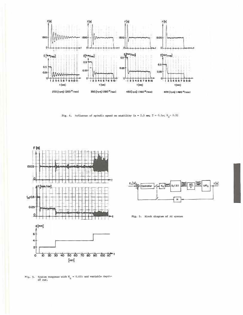
This integral policy has been implemented on a high power CNC lathe. A typical result for K ~ 0.5 is shown in Fig. 2. The feed before engagement was sel~cted as 0 .5 mm/rev. At the start of cutting, the feed is immediately reduced to approximately 0.25 mm/rev. The depth-of-cut is increased by increments of 2 mm, and each time, after a small transient, the force reaches the preselected reference value of Fr= l500N The corresponding feed is decreased. t-lhen increasing the controller gain to Kc:::o: 0.625, an unexpected instability phenomenon ·was encountered. As seen in Fig. 3, the system is stable as long as the depth-of-cut does not exceed 4 mm. But at 6 mm, the system becomes unstable with oscillations of approximately 2 Hz. This is the natural frequency of the servo loop and is not caused by chatter. Furthermore, when running the system with different spindle speeds and constant depth-of-cut, the same phenomenon occurred. With a slower spindle speed, the system became more unstable, as shown in Fig. 4. The big influence of the spindle speed and depth-ofcut on the sys tem stability prompted a more detailed study of the AC loop.
Model of the CNC/AC System
The CNC system of the lathe is based on t he reference pulse method [4], whereby the reference signals from the computer are transmitted as a sequence of pulses for each axis-of-motion, each pulse generating a motion of one basic length-unit (BLU). The accumulated number of pulses represent position, and the pulse frequency is proportional to the axis velocity. In the present system, l BLU ~ 0.01 mm. By assuming that the servo loops can be modelled as a second order system, the transfer function can be written:
(BLU) "'n2 (5)
The relationship between machining feed f and the axis velocity V f is given by:
f a 60 v;n (6)
where n is the spindle speed in rpm. The force F can be assumed to be propor t ional to the feed and depth-of-cut, a:
(7)
where K5
is the specific force coefficient which depends on the workpiece and tool material.
A block diagram representation of the CNC/AC system is shown in Fig. 5. The feedback gain H in Fig. 5 represents the force sensor electronics and ADC gains. The overall open-loop gain K is
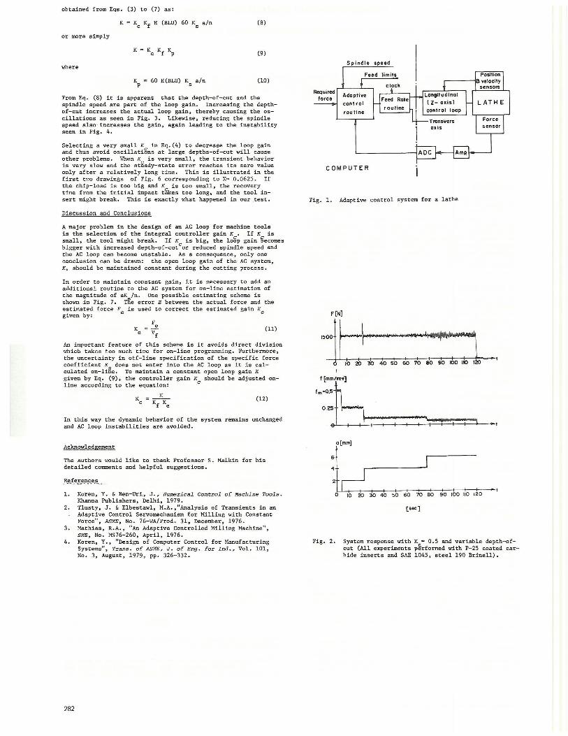
obtained from Eqs. (3) to (7) as:
K = Kc Kf H (BLU) 60 Ks a/n (8)
or more simply
K (9)
where
Kp c 60 H(BLU) Ks a/n (10)
From Eq. (8) it is apparent that the depth-of-cut and the spindle speed are part of the loop gain. Increasing the depthof-cut increases the actual loop gain, thereby causing the oscillations as seen in Fig. 3. Likewise, reducing the spindle speed also· increases the gain, again leading to the instability seen in Fig. 4.
Selecting a very small Kc in Eq.(4) to decrease the loop gain and thus avoid oscillations at large depths-of-cut will cause other problems. tfuen K is very small, the transient behavior is very slow and the stgady- state error reaches its zero value only after a relatively long time. This is illustrated in the f i rst tl·JO drawings of Fig. 6 corresponding to Kc 0 .0625. If the chip-load is too big and Kc is too small, the recovery time from the initial impact takes too long, and the tool insert might break. This is exactly what happened in our .test .
Discussion and Conclusions
A major problem in the design of an AC loop for machine tools is the selection of the integral controller gain K • If K is small, the tool might break. If K is big, the logp gain Eecomes bi gger with increased depth-of- cutcor reduced spindle speed and the AC loop can become unstable. As a consequence, only one conclusion can be drawn: the open loop gain of the AC system, K, should be maintained constant during the cutting process.
In order to maintain constant gain, it is necessary to add an additional routine to the AC system for on-line estimation of the magnitude of aK /n. One possible estimating scheme is shown in Fig. 7. T~e error E between the actual force and the estimated force F is used to correct the estimated gain K ~-n~: e e
K Fe e = vf
(11)
An important featu-re of this scheme is it avoids direct division which takes too much time for on-line programmi ng. Furthermore, the uncertainty in otf- line specification of the specific force coefficient K
5 does not enter into the AC loop as it is cal
culated on-line. To maintain a constant open loop gain K given by Eq. (9), the controller gain Kc should be adjusted online according to the equation:
(12)
In this way the dynamic behavior of the system remains unchanged and AC loop instabilities are avoided.
Acknowledgement
The authors would like to thank Professor S. Malkin for his detailed comments and helpful suggestions.
References
1. Koren, Y. & Ben-Uri, J., Numerica l Control of Machine Tools. Khanna Publishers, Delhi, 1979.
2. Tlusty, J. & Elbestawl, M.A., 11 Analysis of Transients in an Adaptive Control Servomechanism for Milling with Constant Force", ASME, No. 76-WA/Prod. 31, December, 1976.
3. Mathias, R.A., "An Adaptive Controlled Milling Machine", SME, No. MS76-260, April, 1976.
4. Koren, Y., "Design of Computer Control for Manufacturing Systems", Trans. of ASME, J. of Eng. for Ind., Vol. 101, No. 3, August, 1979 , pp. 326- 332.
282
Required force
COMPUTER
Fig. 1. Adaptive control system for a lathe
F(N)
1500
10 20 30 40 so so ro eo 90 100 no 120 I
.~~=6 0.25
e 'T l I
:j~r-3-,0-40-,--so-1 _s_b_ ro_'__.ab ~o 1bo 1lo 1~0 (sec)
• t
Fig. 2. System response with Kc• 0.5 and variable depth- ofcut (All experiments performed with P- 25 coated carbide inserts and SAE 1045, steel 190 Brinell).
F(NJ F[NJ F[NJ F(N]
f(m111/r-']
1 (sec) t[secJ t(sec]
250 (rpm] (200 m/min) 350 [rpm) (280m /min) 450[rpni) ( 360 111/min) 600 [rpfTil ( 480 111/min)
Fig. 4 . Influence of spindb speed on statility (a= 2 .5 nun; T = O. ls ; Kc= 0.5)
F[N] - - --
f·-· r-- 1-- - c--- r- --
- c- '- !--I - - ,- -1--l r-
'""' --- I- -I-
ro 1--- 1·- [-,--
! ·- L__ I -'--
1Hm lm 'nvl ___
J --1- - 1-1- 1-1- -
- -1-
0.25- I; 1-c- -c 1--t - ~ "'-1
·-0
o[mm]
6
I - '-'[ ~. , .. , , ·f 1 ~ - ~
• . .II t ..
~-= ~
- I I L -' 1 I I
1- 1 .1 I I
'
. - i I
. ~
1- ·- 1----
L__~ C....L__
50 60 70 80 90 100 110 t
[sec]
Fig. 3. System response with Kc ~ 0 . 625 and variable de pthof cut.
Fig. 5. Block diagram of AC system

f (N)
t ~ 1500 t ,: '--
oll_________ ____ ~~--~------~~----
('t!M'lNG INST.R'l' !, nooxr. r
f (mm/revl
• t
r-· JJ===I-~ 010 20 30 4050
D~. 01020 30 40
C . 0 10 20
Fip,. 7 . . Ident ification scheme of AC system
[sec]
Fig . 6. System response with Kc~ 0 .0625
284