AD-AI05 724 UNCLASSIFIED mhhlllllllI~rllu BAKER J … PEEKSKILL DAM PUTNAM COUNTY, NEW YORK L...
92
AD-AI05 724 BAKER (MICHAEL) J INC BAVER PA F/6 13/13 NATIONAL DAM SAFETY PROGAM. LAKE PEE S ILL DAM (INVENTORY NUMB--ETClU) AUG LSI E KESTER DACWS1-81-C-O01 UNCLASSIFIED N mhhlllllllI~rllu mhhhhhhhhhhIhl -B-mIIIIIIIII EIEEIIIIIIIEEE IIIIIIIIIIIIIl E-Ellllllllll *IIIIIIIw
Transcript of AD-AI05 724 UNCLASSIFIED mhhlllllllI~rllu BAKER J … PEEKSKILL DAM PUTNAM COUNTY, NEW YORK L...
AD-AI05 724 BAKER (MICHAEL) J INC BAVER PA F/6 13/13NATIONAL DAM SAFETY PROGAM. LAKE PEE S ILL DAM (INVENTORY NUMB--ETClU)AUG LSI E KESTER DACWS1-81-C-O01
UNCLASSIFIED NmhhlllllllI~rllu
mhhhhhhhhhhIhl-B-mIIIIIIIIIEIEEIIIIIIIEEEIIIIIIIIIIIIIlE-Ellllllllll*IIIIIIIw

LAKE PEEKSKILL DAM
PUTNAM COUNTY, NEW YORK L
INVENTORY NO. N.Y. 87
PHASE I INSPECTION REPORTNATIONAL DAM SAFETY PROGRAM
APPROVED Fo,- PUBLIC RELEASE;DISTRIBUTION UNLIMITED DTIC
S~ELECTE
OCT 19 1981
.NEW YORK DISTRICT CORPS OF ENGINEERS
AUGUST 1981
,i(.,., r. •,

SEC U RIT Y C L A SSIFIC AT 10 4 O :
T H IS P G _ (W . -1- 1 ,t.p-. d)
REPORT DOCUMENTATION PAGE BEFORE CO TI UC'rIOR _COP-T' FORM4
1. REPORT UPOPEM . lGOVT ACCES51IO 3L. PECIPIz.T'S CAT AtL-G MU b
4. TITLE (And 5.-beitle) TYPE OP R-PORfT &q P'tOD COVERED
Phase I Inspection Report Phase I Inspection ReportLake Peekskill Dam ,National Dam Safety ProgramLower Hudson River Basin, Putnam County, NY 6. PoGo.R pORTHU'Inventory_1f. 87..-
AUTHO ( 7 CONTRACT OR GR^HlT NUAMi3ZR-Y.
.RANVILL .ESTER R DACW5181-C-000
3. PERPORMIMG ORGaNIZATION NAME AND ADDRESS * 10. pRO,_pAwN tuEeNT. POJ-3CT. TASK.IMichael *Baker, Jr. Inc. ARZA & oR,( ukar 4ureaRs
4301 Dutch Ridge RoadPox 280 - I
Beaver, PA 15009 .r 1. COiKTROjLItNGoi;ICE NAME ANO ADDPESS Q;-
Department of the Army ,14 AugaMWI81
26 Federal Plaza New York Dis-:rict, CofE S Numaeo OW ...r.
New York, New York 10287 II . moN.ITORtiG AGENCY NAMIE & AOORESS(II dl.,er.nt trom CQvfrol0lM Ol1C.)Department of the Army26 Federal Plaza New York " i ;CLSSIFIED
New YorkE ANY 10287PSo.IORIDNew ork ~NY1027 (SCHEDULE
16. DISTFAlBUTION STATE.4ENT (of tisl Repo
Approved for public release; Distribution unlimited.
National Dam Safety Progra.. Lake .4
17. tISTRISUTI.O .r Peekskill Dam (Inventory Number NY. 87)Lower Hudson River Basin, Putnam CountyNew York. Phase I Inspection Report
Il. SUPPLEMENTARY NOTES-
Is. Ky QROS (ComI on s'..eI d. im=e.esm7 .d Identi y by blok n...) " ,.
Dan Safety Lake Peekskill Dam
National Dam Safety Program Putnam CountyVisual Inspection- Lower Hudson River BasinHydrology, S=---ctural Stability
This rep. p:ovides information a-td analysis on h-- 'i-sical cond:iaet oLa :0'inspectib.- the dam by the perF-~.),ing organization. '-
. Examination of available documents and a visual inspec-u;on of the dam and appurtenant structures did not reveal:.ditions which constitute an immediate hazard to human:if* or property.
"I 9tO cornm r Nov em IS ORS-3LX? CLrIE*IO PT#PG~(~..StCU~h4 Csmrcneo wi act

SKCURITY CLASSIFICATI3,1 OF THIS FAGE(W ?h., D*$1. 1Entor.d)
Using the Corps of Engineers' screening criteria, it.as been determined that the dam would be overtopped for all
orms exceeding approximately 77 percent of the Probable':.ximum Flood (PMF). Therefore, the spillway is adjudgedinadequate."
Structural stability analyses based on available i orma-'Iton, indicate that the factors of safety against overturning
:e generally low, and the locations of the resultants fall.tside the middle 1/3 (except for analyses of the normalol loading conditions). When the dam is subjected to.'ere loading conditions such as an ice load or a PMF
-.et, the factors of safety fall to critical levels...-erefore, it is recommended that further analyses of the':uctural stability be performed within three months of'.er notification. These analyses will determine the
• *;'ProDriate remedial measures required.
Formal inspection and maintenance procedures should beSe'cped with records maintained for future reference.
A formal warning system and emergency action plan-..1d be developed and put into operation as soon as possible.
The seeps should be monitored at regular intervals for•.:ity and increase in flow.
Accssi on ForNTIS GRA&IDTIC TABUnannounced [ ELECT.-I3ustificatior_ _O!T 19 1
_ _ _ _ S9 1981JByDistribution/Availability Codes
Avail and/or
Dist. Special
- 4
SECURITY CLAS!;'ICA.;:ON OF THIS PAF.( ' e. g!d F.r.rtpd)
I LIIF1 : -- ,l: . Z : Z i I II II

7i _
PREFACE
This report is prepared under guidance contained in theRecommended Guidelines for Safety Inspection of Dams, forPhase I Investigations. Copies of these guidelines may beobtained from the Office of Chief of Engineers, Washington,D.C. 20314. The purpose of a Phase I Investigation is toidentify expeditiously those dams which may pose hazards tohuman life or property. The assessment of the generalcondition of the dam is based upon available data and visualinspections. Detailed investigation and analyses involvingtopographic mapping, subsurface investigations, testing, anddetailed computational evaluations are beyond the scope of aPhase I Investigation; however, the investigation is intendedto identify any need for such studies.
In reviewing this report, it should be realized that thereported condition of the dam is based on observations of fieldconditions at the time of inspection along with data availableto the inspection team. In cases where the reservoir waslowered or drained prior to inspection, such action, whileimproving the stability and safety of the dam, removes thenormal load on the structure and may obscure certain conditionswhich might otherwise be detectable if inspected under thenormal operating environment of the structure.
It is important to note that the condition of a damdepends on numerous and constantly changing internal andexternal conditions, and is evolutionary in nature. It wouldbe incorrect to assume that the present condition of the damwill continue to represent the condition of the dam at somepoint in the future. Only through frequent inspections canunsafe conditions be detected and only through continued careand maintenance can these conditions be prevented orcorrected.
Phase I inspections are not intended to provide detailedhydrologic and hydraulic analyses. In accordance with theestablished Guidelines, the Spillway Test flood is based on theestimated "Probable Maximum Flood" for the region (greatestreasonably possible storm runoff), or fractions thereof.Because of the magnitude and rarity of such a storm event, afinding that a spillway will not pass the test flood should notbe interpreted as necessarily posing a highly inadequatecondition. The test flood provides a measure of relativespillway capacity and serves as an aide in determining the needfor more detailed hydrologic and hydraulic studies,considering the size of the dam, its general condition and thedownstream damage potential.
PHASE I INSPECTION REPORTNATIONAL DAM SAFETY PROGRAM
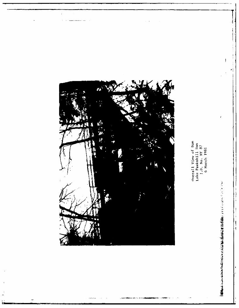
LAKE PEEKSKILL DAMI.D. No. NY 87
DEC DAM No. 213C-814 LOWER HUDSON RIVER BASINPUTNAM COUNTY, NEW YORK
TABLE OF CONTENTS
PAGE NO.
ASSESSMENT
OVERVIEW PHOTOGRAPH
PROJECT INFORMATION 1
1.1 GENERAL 11.2 DESCRIPTION OF PROJECT 11.3 PERTINENT DATA 2
2 ENGINEERING DATA 5
2.1 GEOLOGY 52.2 SUBSURFACE INVESTIGATION 52.3 DAM AND APPURTENANT STRUCTURES 62.4 CONSTRUCTION RECORDS 62.5 OPERATION RECORDS 62.6 EVALUATION OF DATA 6
3 VISUAL INSPECTION 7
3.1 FINDINGS 73.2 EVALUATION 8
4 OPERATION AND MAINTENANCE PROCEDURES 9
4.1 PROCEDURES 94.2 MAINTENANCE OF THE DAM 94.3 WARNING SYSTEM 94.4 EVALUATION 9
5 HYDRAULIC/HYDROLOGIC 11
5.1 DRAINAGE AREA CHARACTERISTICS 115.2 ANALYSIS CRITERIA 115.3 SPILLWAY CAPACITY 115.4 RESERVOIR CAPACITY 115.5 FLOODS OF RECORD 125.6 OVERTOPPING POTENTIAL 125.7 RESERVOIR EMPTYING POTENTIAL 125.8 EVALUATION 12
PAGE NO.
6 STRUCTURAL STABILITY 13
6.1 EVALUATION OF STRUCTURAL STABILITY 136.2 STABILITY ANALYSIS 146.3 SEISMIC STABILITY 15
7 ASSESSMENT/RECOMMENDATIONS 17
7.1 ASSESSMENT 177.2 RECOMMENDED MEASURES 17
APPENDIX
A. PHOTOGRAPHS
B. VISUAL INSPECTION CHECKLIST
C. HYDROLOGIC/HYDRAULIC DATA AND COMPUTATIONS
D. REFERENCES
E. DRAWINGS
F. BACKGROUND DOCUMENTS
G. STABILITY COMPUTATIONS
I,II

PHASE I INSPECTION REPORTNATIONAL DAM SAFETY PROGRAM
Name of Dam: Lake Peekskill Dam (I.D. No. NY 87)
State: New York
County: Putnam
Stream: Unnamed Tributary of Peekskill HollowBrook
Date of Inspection: 6 March 1981
ASSESSMENT
Examination of available documents and a visual inspec-tion of the dam and appurtenant structures did not revealconditions which constitute an immediate hazard to humanlife or property.
Using the Corps of Engineers' screening criteria, ithas been determined that the dam would be overtopped for allstorms exceeding approximately 77 percent of the ProbableMaximum Flood (PMF). Therefore, the spillway is adjudged"inadequate."
Structural stability analyses based on available informa-tion, indicate that the factors of safety against overturningare generally low, and the locations of the resultants falloutside the middle 1/3 (except for analyses of the normalpool loading conditions). When the dam is subjected tosevere loading conditions such as an ice load or a PMFevent, the factors of safety fall to critical levels.Therefore, it is recommended that further analyses of thestructural stability be performed within three months ofowner notification. These analyses will determine theappropriate remedial measures required.
Formal inspection and maintenance procedures should bedeveloped with records maintained for future reference.
A formal warning system and emergency action planshould be developed and put into operation as soon as possible.
The seeps should be monitored at regular intervals forturbidity and increase in flow.
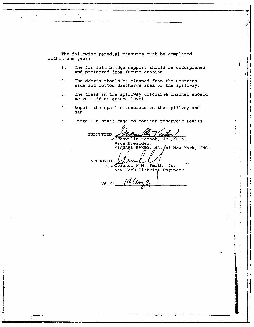
The following remedial measures must be completedwithin one year:
1. The far left bridge support should be underpinnedand protected from future erosion.
2. The debris should be cleaned from the upstreamside and bottom discharge area of the spillway.
3. The trees in the spillway discharge channel shouldbe cut off at ground level.
4. Repair the spalled concrete on the spillway anddam.
5. Install a staff gage to monitor reservoir levels.
SUBMITTEs , .
Vice, residentMIC L BAK, R. of New York, INC.
APPROVED: o.onel W.M. Smi h, Jr.
New York District Engineer
DATE:
* ..4i i
0 C
-4
'-4 M~ 0 Li>-14 z w
a) cc-wu*
PHASE I INSPECTION REPORTNATIONAL DAM SAFETY PROGRAM
LAKE PEEKSKILL DAMI.D. No. NY 87
DEC DAM No. 213C-814LOWER HUDSON RIVER BASIN 'I
PUTNAM COUNTY, NEW YORK
SECTION 1: PROJECT INFORMATION
1.1 GENERAL
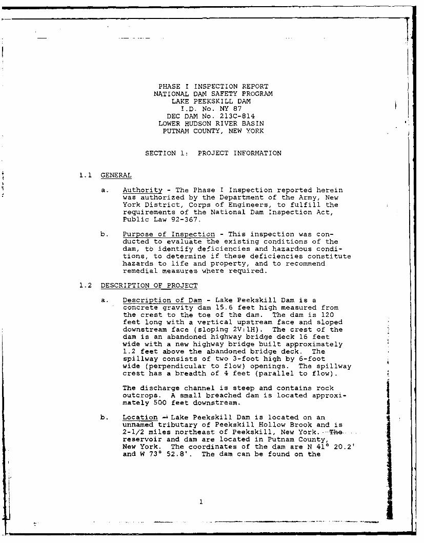
a. Authority - The Phase I Inspection reported hereinwas authorized by the Department of the Army, NewYork District, Corps of Engineers, to fulfill therequirements of the National Dam Inspection Act,Public Law 92-367.
b. Purpose of Inspection - This inspection was con-ducted to evaluate the existing conditions of thedam, to identify deficiencies and hazardous condi-tions, to determine if these deficiencies constitutehazards to life and property, and to recommendremedial measures where required.
1.2 DESCRIPTION OF PROJECT
a. Description of Dam - Lake Peekskill Dam is aconcrete gravity dam 15.6 feet high measured fromthe crest to the toe of the dam. The dam is 120feet long with a vertical upstream face and slopeddownstream face (sloping 2V:lH). The crest of thedam is an abandoned highway bridge deck 16 feetwide with a new highway bridge built approximately1.2 feet above the abandoned bridge deck. Thespillway consists of two 3-foot high by 6-footwide (perpendicular to flow) openings. The spillwaycrest has a breadth of 4 feet (parallel to flow).
The discharge channel is steep and contains rockoutcrops. A small breached dam is located approxi-mately 500 feet downstream. j
b. Location -- Lake Peekskill Dam is located on anunnamed tributary of Peekskill Hollow Brook and is2-1/2 miles northeast of Peekskill, New York.--T4e.reservoir and dam are located in Putnam County,New York. The coordinates of the dam are N 410 20.2'and W 730 52.8'. The dam can be found on the
!1
Peekskill, New York, USGS 7.5 minute topographicquadrangle. A Location Map is shown in Appendix E.
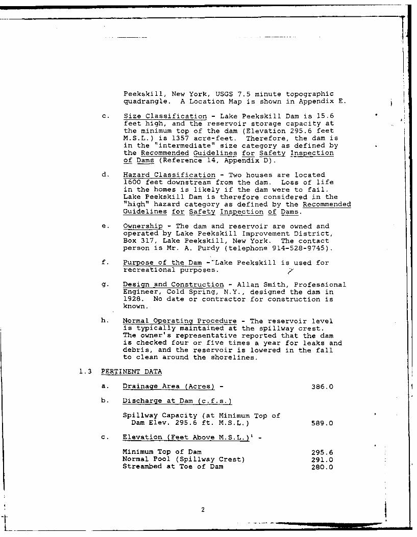
C. Size Classification - Lake Peekskill Dam is 15.6feet high, and the reservoir storage capacity atthe minimum top of the dam (Elevation 295.6 feetM.S.L.) is 1357 acre-feet. Therefore, the dam isin the "intermediate size category as defined bythe Recommended Guidelines for Safety Inspectionof Dams (Reference 14, Appendix D).
d. Hazard Classification - Two houses are located1600 feet downstream from the dam. Loss of lifein the homes is likely if the dam were to fail.Lake Peekskill Dam is therefore considered in the"high" hazard category as defined by the RecommendedGuidelines for Safety Inspection of Dams.
e. Ownership - The dam and reservoir are owned andoperated by Lake Peekskill Improvement District,Box 317, Lake Peekskill, New York. The contactperson is Mr. A. Purdy (telephone 914-528-9745).
f. Purpose of the Dam --Lake Peekskill is used forrecreational purposes.
g. Design and Construction - Allan Smith, ProfessionalEngineer, Cold Spring, N.Y., designed the dam in1928. No date or contractor for construction isknown.
h. Normal Operating Procedure - The reservoir levelis typically maintained at the spillway crest.The owner's representative reported that the damis checked four or five times a year for leaks anddebris, and the reservoir is lowered in the fallto clean around the shorelines.
1.3 PERTINENT DATA
a. Drainage Area (Acres) - 386.0
b. Discharge at Dam (c.f.s.)
Spillway Capacity (at Minimum Top ofDam Elev. 295.6 ft. M.S.L.) 589.0
C. Elevation (Feet Above M.S.L.)' -
Minimum Top of Dam 295.6Normal Pool (Spillway Crest) 291.0Streambed at Toe of Dam 280.0
2

d. Reservoir Surface (Acres) -
Top of Dam (Elev. 295.6 ft. M.S.L.) 67.0Spillway Crest (Elev. 291.0 ft. M.S.L.) 52.0
e. Reservoir Storage Capacity (Acre-Feet) -
Top of Dam (Elev. 295.6 ft. M.S.L.) 1357.0Spillway Crest (Elev. 291.0 ft. M.S.L.) 1074.0
f. Dam -
Type: Concrete gravityLength (Feet) 120.0Height (Feet) 15.6Top Width (Feet) 16.0Side Slopes - Upstream Vertical
Downstream 2V:lHg. Spillway -
Type: Two 3-ft. x 6-ft. openings.Crest Length Perpendicular to Flow (Feet) 12.0Crest Width Parallel to Flow (Feet) 4.0Crest Elevation (Feet M.S.L.) 291.0
h. Reservoir Drain -
The original 24-inch outlet pipe was plugged withconcrete in 1948. Therefore, the outlet pipe isnot operable.
2
*1
'All elevations are referenced to the spillway crest, Elev.291.0 ft. M.S.L., estimated from the USGS 7.5 minute topo-graphic quadrangle, Peekskill, NY.
3 1
SECTION 2: ENGINEERING DATA
2.1 GEOLOGY
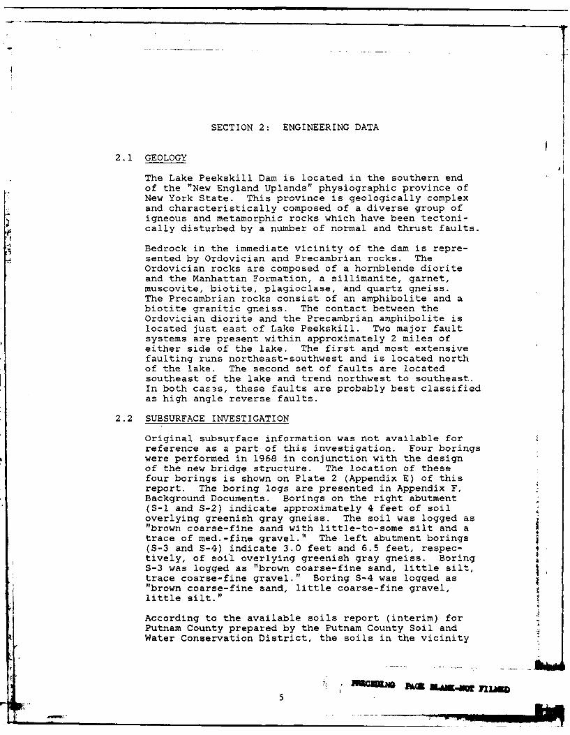
The Lake Peekskill Dam is located in the southern endof the "New England Uplands" physiographic province ofNew York State. This province is geologically complexand characteristically composed of a diverse group ofigneous and metamorphic rocks which have been tectoni-cally disturbed by a number of normal and thrust faults.
Bedrock in the immediate vicinity of the dam is repre-sented by Ordovician and Precambrian rocks. TheOrdovician rocks are composed of a hornblende dioriteand the Manhattan Formation, a sillimanite, garnet,muscovite, biotite, plagioclase, and quartz gneiss.The Precambrian rocks consist of an amphibolite and abiotite granitic gneiss. The contact between theOrdovician diorite and the Precambrian amphibolite islocated just east of Lake Peekskill. Two major faultsystems are present within approximately 2 miles ofeither side of the lake. The first and most extensivefaulting runs northeast-southwest and is located northof the lake. The second set of faults are locatedsoutheast of the lake and trend northwest to southeast.In both casas, these faults are probably best classifiedas high angle reverse faults.
2.2 SUBSURFACE INVESTIGATION
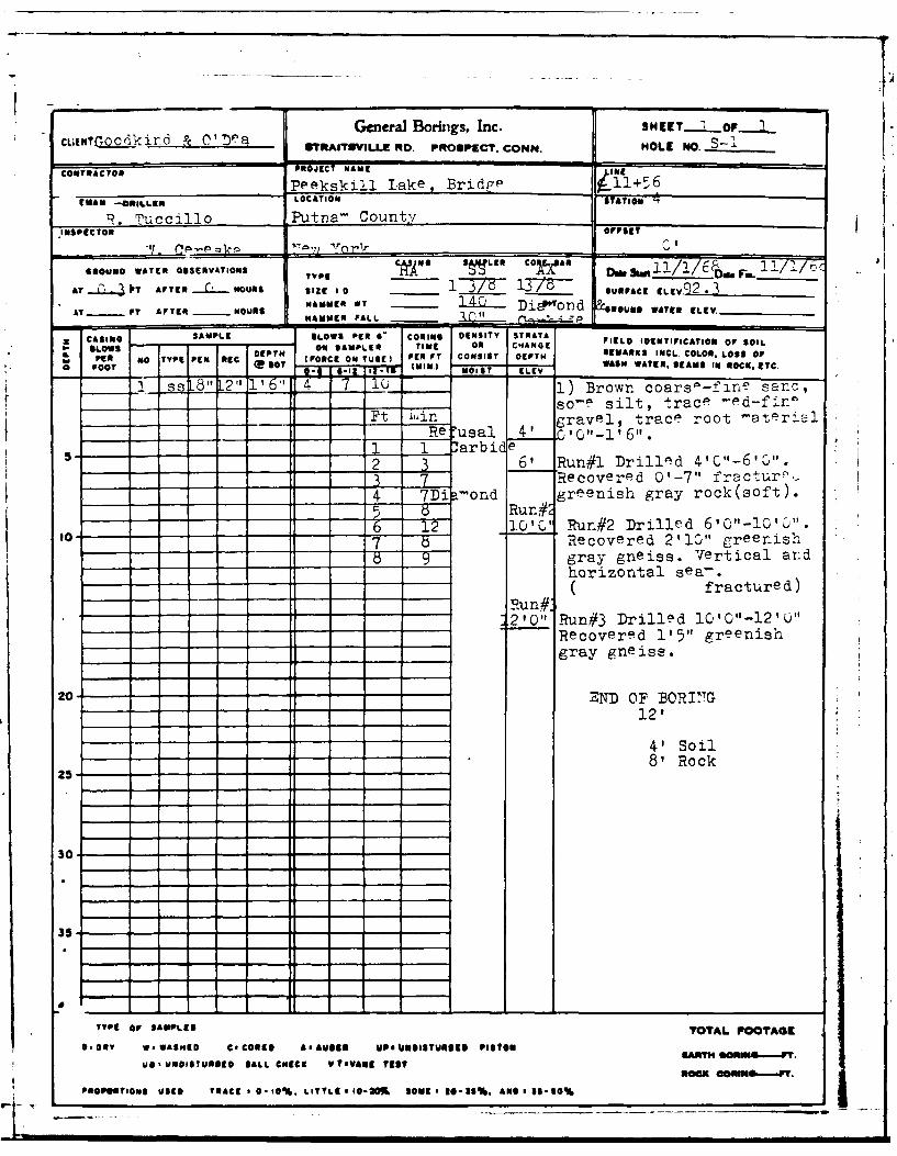
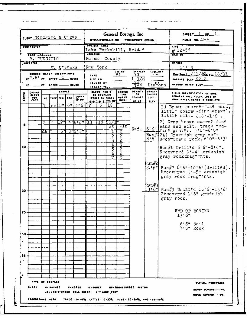
Original subsurface information was not available forreference as a part of this investigation. Four boringswere performed in 1968 in conjunction with the designof the new bridge structure. The location of thesefour borings is shown on Plate 2 (Appendix E) of thisreport. The boring logs are presented in Appendix F,Background Documents. Borings on the right abutment(S-1 and S-2) indicate approximately 4 feet of soiloverlying greenish gray gneiss. The soil was logged as"brown coarse-fine sand with little-to-some silt and atrace of med.-fine gravel." The left abutment borings(S-3 and S-4) indicate 3.0 feet and 6.5 feet, respec-tively, of soil overlying greenish gray gneiss. BoringS-3 was logged as "brown coarse-fine sand, little silt,trace coarse-fine gravel." Boring S-4 was logged as"brown coarse-fine sand, little coarse-fine gravel,little silt."
According to the available soils report (interim) forPutnam County prepared by the Putnam County Soil andWater Conservation District, the soils in the vicinity
5

of the dam are of the Hollis-Charlton Association.These soils are described as "shallow, excessively-to-well drained, sandy loam soils and deep, well-drainedstony, sandy loam soils that have a permeable subsoiland substratum."
2.3 DAM AND APPURTENANT STRUCTURES
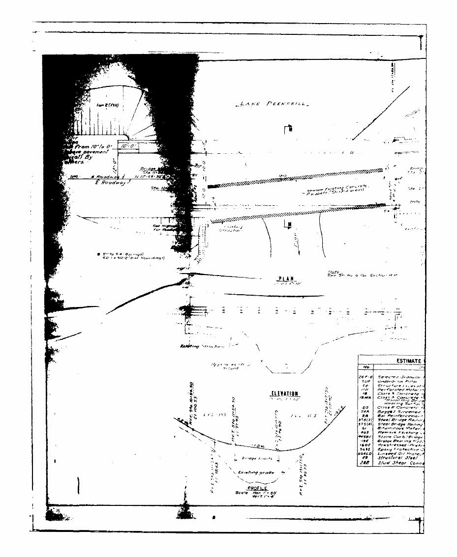
Plans for the dam and original bridge prepared by AllanSmith, P.E., Cold Spring, New York, circa 1928, wereobtained from Mr. Ron Kobbe, Putnam County HighwayDepartment, 351 Fair Street, Carmel, New York 10512.Design drawings for the new bridge, circa 1969, werealso obtained from Mr. Kobbe.
The dam is a concrete semi-gravity dam with a verticalupstream face, crest width of 16 feet and a slopeddownstream face (sloping 2V:IH). The spillway consistsof two 3-foot high by 6-foot wide openings. A highwaybridge has been built above the dam.
2.4 CONSTRUCTION RECORDS
No construction records were available for thisinvestigation.
2.5 OPERATION RECORDS
Formal operation records are not maintained by theowner. The dam is checked four or five times annuallyfor leaks and debris, and the reservoir is lowered inthe fall to clean around the shorelines.
2.6 EVALUATION OF DATA
The background information collected during this investi-gation was obtained primarily from the New York StateDepartment of Environmental Conservation files. Supple-mentary information was acquired through conversationswith Mr. A. Purdy, representing the Lake PeekskillImprovement District. Design drawings were obtainedthrough Mr. Kobbe of the Putnam County Highway Department.The available data are considered adequate and reliablefor Phase I Inspection purposes.
6
i •
SECTION 3: VISUAL INSPECTION
3.1 FINDINGS
a. General - The inspection was performed on 6 March1981. The weather was sunny with a temperature of30'F. One to two inches of snow had fallen twodays previously, but the dam and structures werenot covered during the inspection. The watersurface was 0.5 feet above the crest. Deficienciesfound during the inspection will require remedialtreatment. A Field Sketch of conditions foundduring the inspection is included in Appendix E.The complete Visual Inspection Checklist is pre-sented as Appendix B.
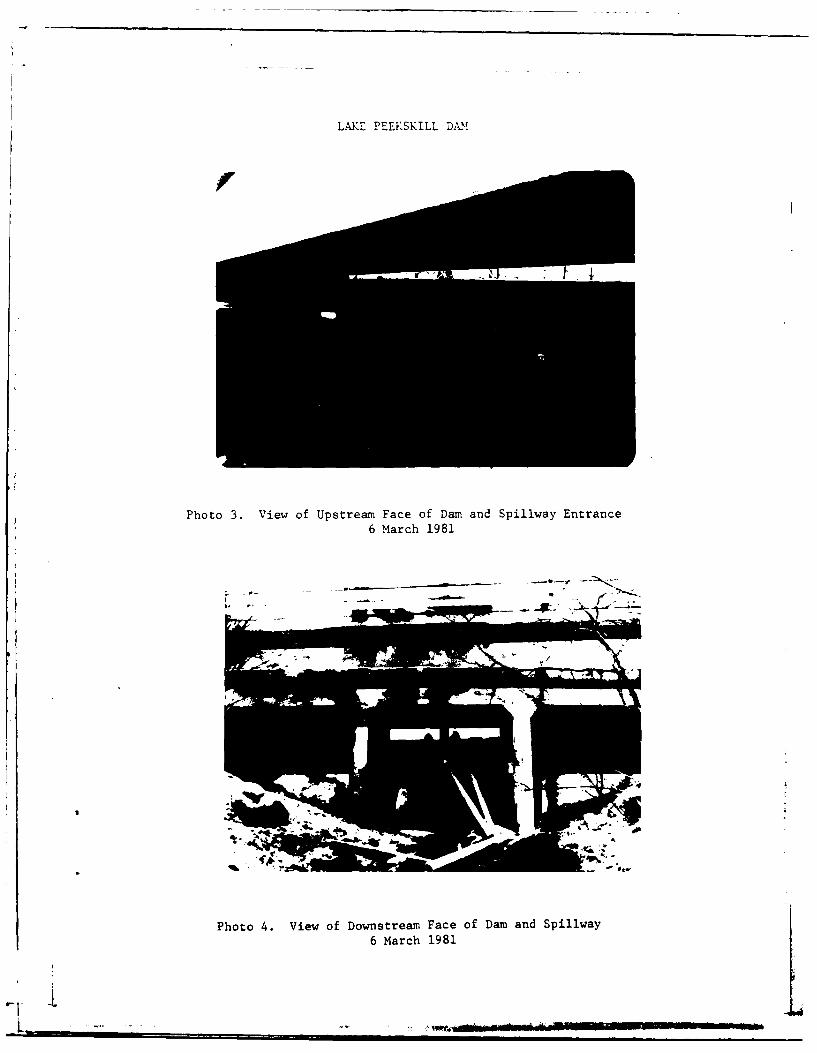
b. Spillway - The spillway consists of two 3-foot x6-foot openings and is located 25 feet from theleft abutment. The two openings were 4 feet wide.
Debris was located on the upstream side of thespillway and where the spillway junctions with thedischarge channel.
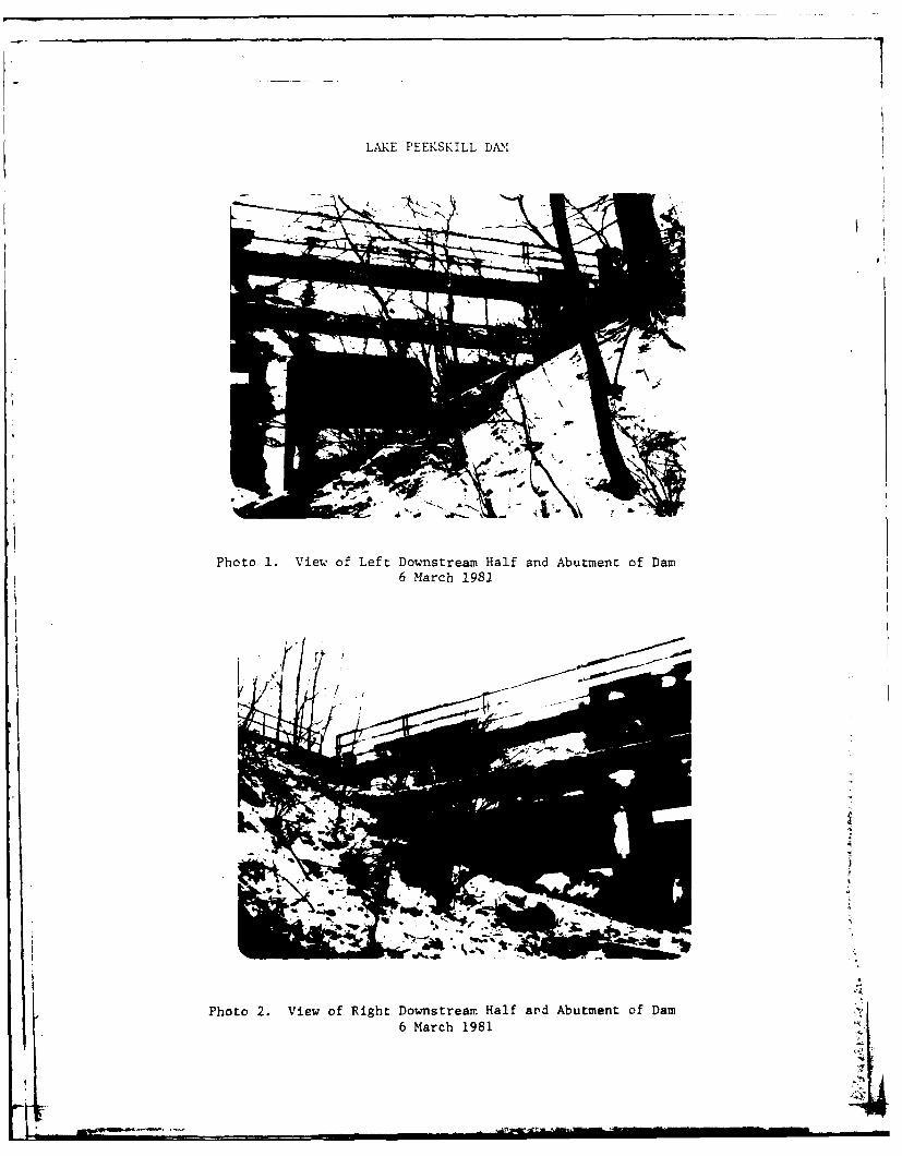
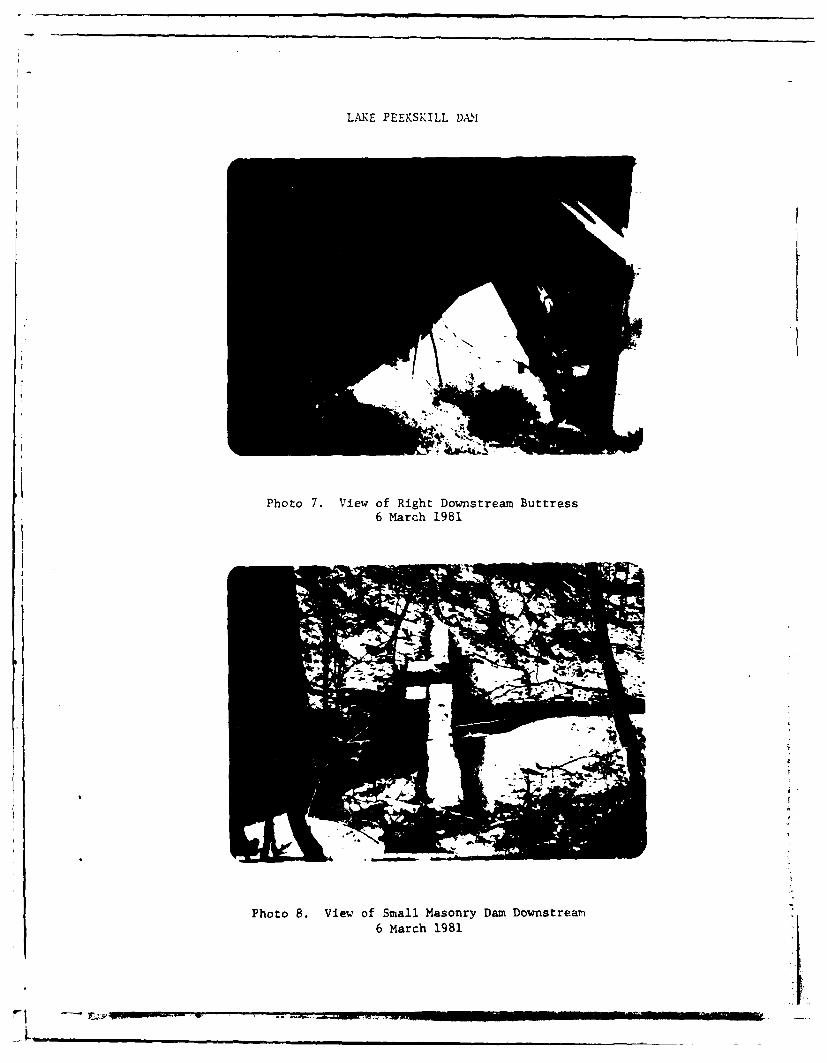
c. Dam - The dam is a concrete structure 120 feetlong with a height of 15.6 feet. An abandonedbridge deck is the top of the dam, and a newbridge is located 1.2 feet above this structure.Seepage was observed exiting from the right down-stream buttress near the spillway. This concretebuttress is also spalled and partially deteriorated.Seepage was also observed 2 feet from the leftbridge column of the abandoned bridge. The owner'srepresentative reported seeing seepage exitingfrom the right toe of the dam near the spillway.The inspection team was unable to locate thisseepage because of the debris present at thislocation. The abandoned bridge deck is spalled.The far left downstream (abandoned) bridge supporthas been undermined. No major cracking of the damwas observed.
d. Outlet Works - The outlet works for the dam are nolonger operable, as they are filled with concrete.The only means of lowering the reservoir level isby two 6-inch PVC pipes (used as siphons) placedover the spillway crest.
e. Downstream Channel - The downstream channel issteep and contains rock outcrops. Trees arelocated in the channel.
7

A small breached dam structure is located approxi-mately 500 feet downstream. This dam is currentlynon-impounding but would impound water if excessivelyheavy flows in the creek were greater than thecapacity of the breached portion. This structureis of masonry construction and is in need ofrepair.
Two houses and a road are located 1600 feet down-stream from the dam. The stream flows through a48-inch diameter culvert under the road.
f. Reservoir - The slopes of the reservoir are moderateand covered by homes and vegetation. There wereno signs of instability, and sedimentation was notreported to be a problem.
3.2 EVALUATION
- The visual inspection revealed several deficiencies inthis structure. The following items were noted:
l.' Seepage was observed exiting the right downstreambuttress near the spillway,
2. Seepage was observed exiting near the downstreamleft bridge column of the abandoned bridge.
3. Seepage was observed at the right toe of the dam.
4. The far left bridge support has been undermined.
5. Debris was located on the upstream side of thespillway
6. Debris was located at toe of the spillway dischargearea.
7. The outlet works have been sealed and are no
longer operable)
8. Trees are located in the discharge channel,, ,,
9. The spillway and dam have minor spalling on itsconcrete surfaces,
/
8
SECTION 4: OPERATION AND MAINTENANCE PROCEDURES
4.1 PROCEDURES
There are no formal written instructions for operatingthe reservoir. The normal water surface elevation isat the spillway crest, but because of recent precipita-tion, the water surface was 0.5 feet above the crest atthe time of the inspection. The reservoir is used forrecreation. Two 6-inch PVC pipes (used as siphons) wereon the spillway crest.
4.2 MAINTENANCE OF THE DAM
Maintenance of the dam is the responsibility of theLake Peekskill Improvement District. The maintenanceforeman checks the dam four or five times a year. Hevisually inspects it for cracks and seepage. Maintenanceis performed when funds are available.
4.3 WARNING SYSTEM
At the time of the inspection, there was no warningsystem or emergency action plan in operation.
4.4 EVALUATION
Past maintenance of the dam and operating facilitiesappears to have been adequate, but the past activitieshave gone undocumented. A checklist should be compiledby the owner's representative to document the findingsmade during the periodic inspections and the maintenanceitems completed. A warning system and emergency actionplan should be developed and put into operation.
9
SECTION 5: HYDRAULIC/HYDROLOGY
5.1 DRAINAGE AREA CHARACTERISTICS
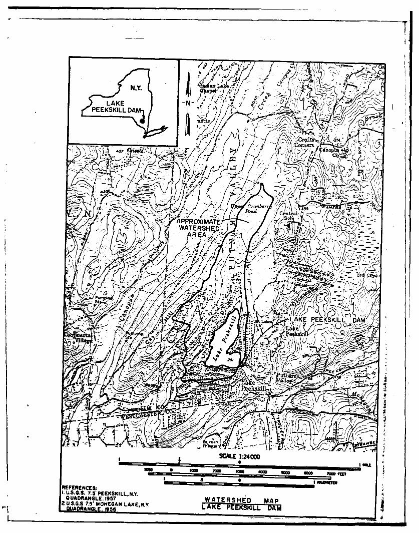
Delineation of the watershed of Lake Peekskill Dam wasmade using the USGS quadrangle for Peekskill, New York.The drainage basin has steep slopes near the reservoirwith extensive lakeside development in the 386-acredrainage area. No storage exists upstream of thereservoir.
5.2 ANALYSIS CRITERIA
A hydrologic analysis of the watershed and hydraulicanalysis of the dam was conducted using the U.S. ArmyCorps of Engineers' Flood Hydrograph Package HEC-l DBcomputer program (Reference 12, Appendix D). The unithydrograph was defined using the Snyder's Unit HydrographMethod. Estimates of Snyder's hydrograph coefficientswere developed from average coefficients from theHydrologic Flood Routing Model for Lower Hudson RiverBasin (Reference 16, Appendix E). Precipitation datawas taken from Hydrometeorological Report No. 33 (Refer-ence 8, Appendix D). Rainfall losses were estimated atan initial loss of 1.0 inch and a constant loss rate of0.1 inch per hour thereafter. The hydraulic capacityof the dam, reservoir and spillway was determined byincorporating the Modified Puls Routing Method. Allflood routings were begun with the reservoir at normalpool level. Outlet discharge capacity was computed byhand. The Probable Maximum Flood (PMF) and 1/2 ProbableMaximum Flood (1/2 PMF) were developed and routedthrough the reservoir.
5.3 SPILLWAY CAPACITY
The spillway consists of two 3-foot by 6-foot openingsnear the center of the dam. The spillway has a capacityof 589 cubic feet per second (c.f.s.) at the top of thedam. There is no auxiliary or emergency spillway at LakePeekskill Dam.
5.4 RESERVOIR CAPACITY
The storage capacity of Lake Peekskill Dam at normal
pool is 1074 acre-feet. The storage capacity of thereservoir at the minimum top of dam is 1357 acre-feet.Therefore, flood control storage of the reservoirbetween the spillway crest and top of dam is 283 acre-feet. This volume represents a total of 8.80 inches ofrunoff from the watershed.
WMM i WJWm 12UM11
Pb.. -.

5.5 FLOODS OF RECORD
No information concerning the effects of significantfloods on the dam is available.
5.6 OVERTOPPING POTENTIAL
The maximum capacity of the spillway is 589 c.f.s.before overtopping would occur. The peak outflows ofthe PMF and 1/2 PMF are 693 c.f.s. and 316 c.f.s.,respectively. Therefore, the spillways are capable ofpassing 77 percent of the PMF before overtopping wouldoccur.
5.7 RESERVOIR EMPTYING POTENTIAL
The reservoir can be drawn down by two 6-inch P.V.C.siphon pipes. The maintenance foreman stated that ittakes one month to lower the reservoir 4 to 5 feet.
5.8 EVALUATION
Lake Peekskill Dam is an "intermediate" size - "high"hazard dam requiring the spillway to pass the PMF. ThePMF and 1/2 PMF were routed through the watershed anddam. It was determined that the spillway is capable ofpassing 77 percent of the PMF before overtopping thedam. Therefore, the spillway is judged "inadequate."
Conclusions pertain to present conditions and theeffect of future development on the hydrology has notbeen considered.
- . 12

SECTION 6: STRUCTURAL STABILITY
6.1 EVALUATION OF STRUCTURAL STABILITY
a. Visual Observations - No signs of instability wereobserved during the field inspection. Minorproblems observed which may affect the stabilityof the structure include:
1. Clear seepage was observed exiting the rightdownstream buttress near the spillway.
2. Clear seepage was observed exiting near theleft downstream bridge column of the abandonedbridge.
3. The spillway and dam have minor spalling,especially at the point of seepage exiting onthe right downstream buttress, on its concretesurfaces. No major cracks were observed.
4. The owner's representative reported seepageexiting at the right toe of the spillway.However, this seepage was not observed due tothe amount of debris present at this location.
5. The left downstream abandoned bridge columnfooting is partially undermined.
b.' Design and Construction Data - Design informationregarding the stability of the structure isunavailable.
c. Operating Records - Operating records are unavail-able. The reservoir is typically at the sameelevation as the spillway crest, except during the1 October to 31 December period when the reservoiris drawn down 4 to 5 feet to facilitate shorelineand dock maintenance.
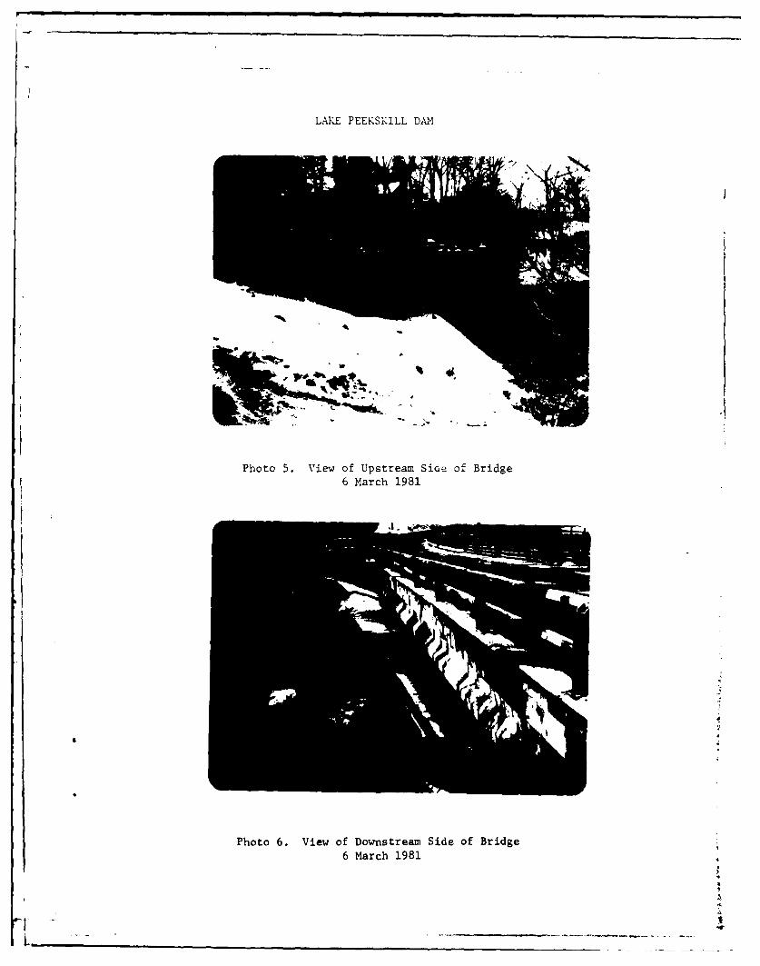
d. Post Construction Changes - The structure wasbuilt circa 1928. The outlet drain pipe wasplugged with concrete in 1948. Around 1970, a newbridge was installed spanning over the dam toreplace the existing bridge deck founded on thecrest of the dam. The previous bridge deck wasthen left in place and abandoned.
ii. 13________ * ,.SWL'__________________

t
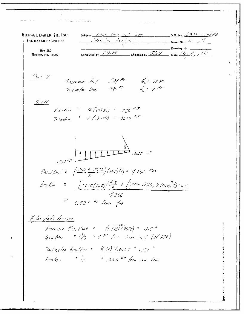
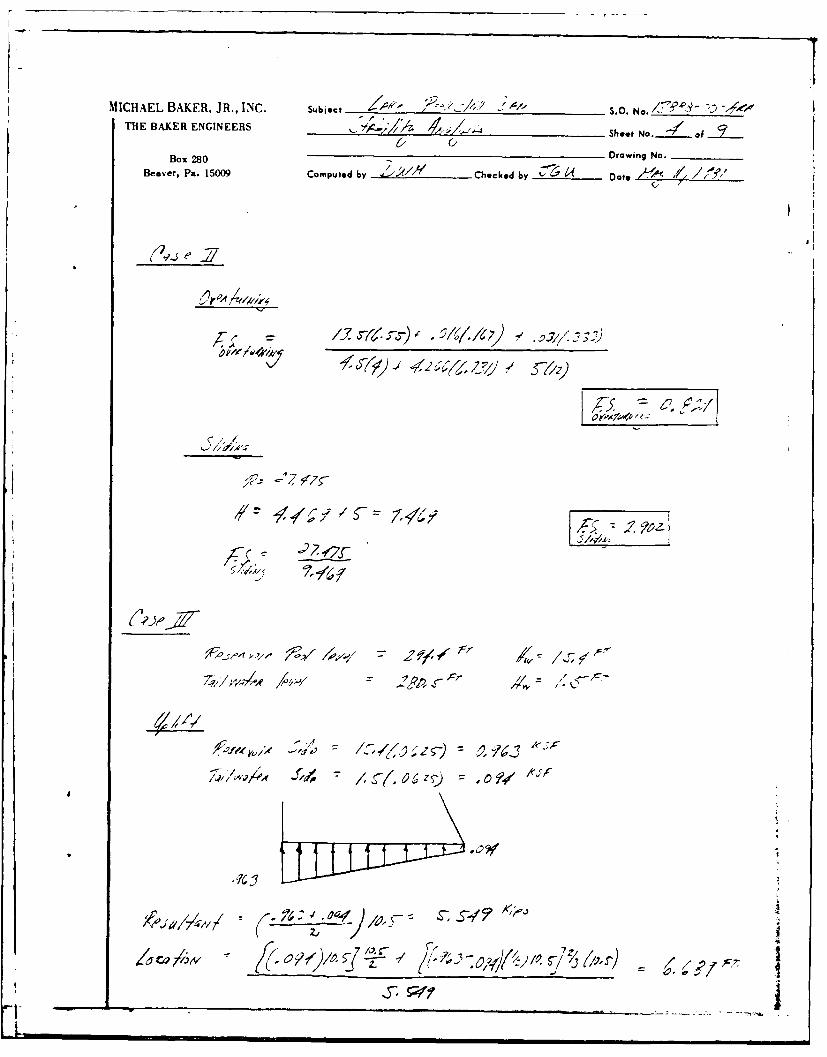
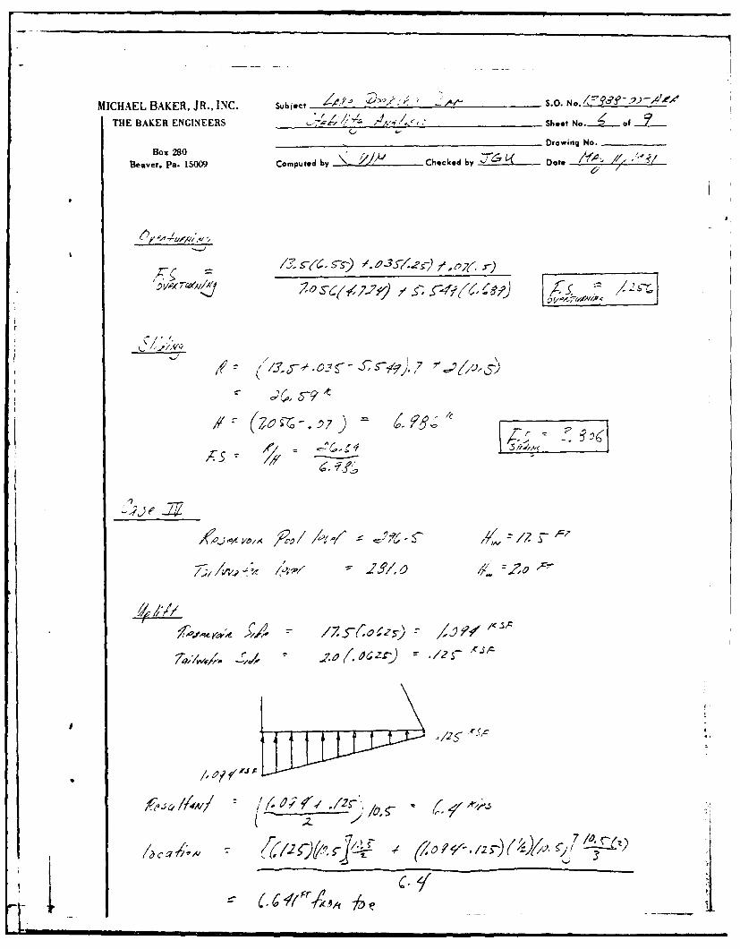
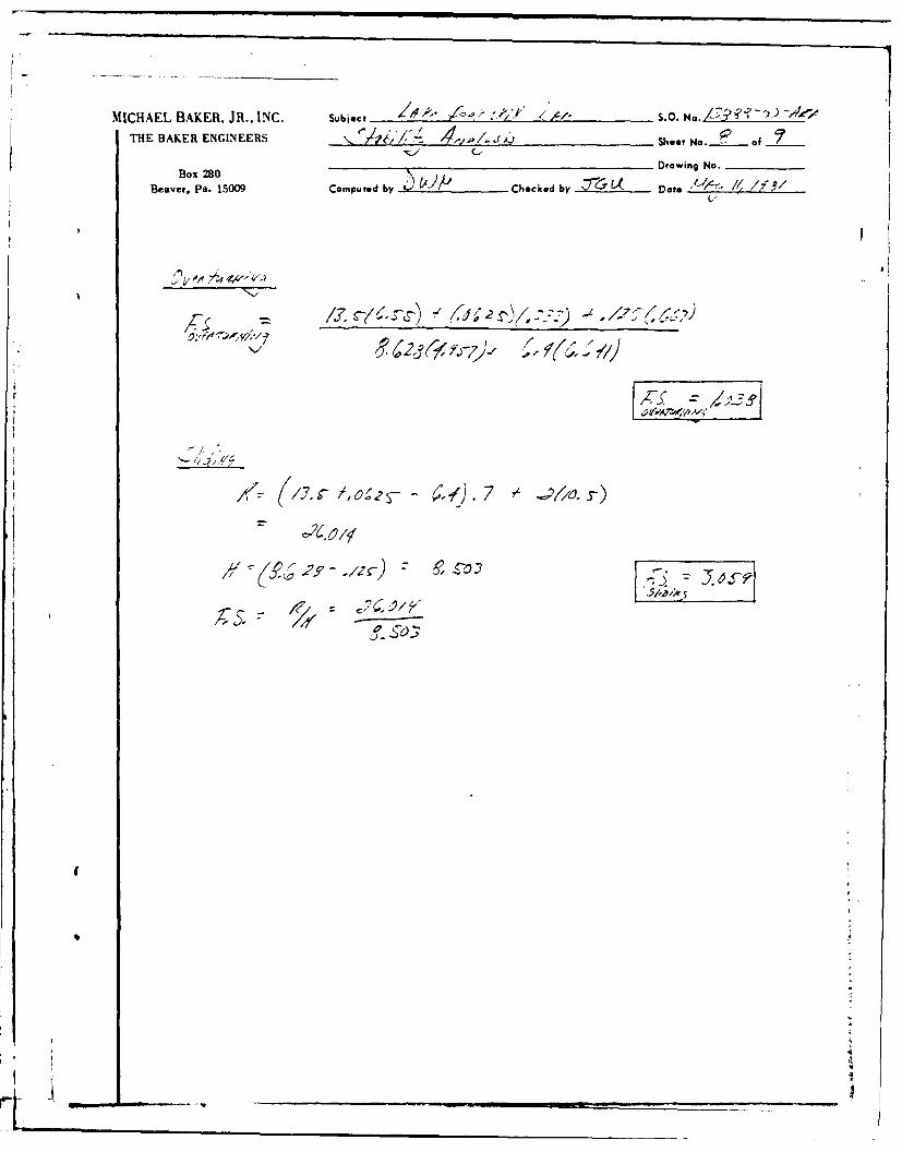
6.2 STABILITY ANALYSIS
The results of any previous stability analyses wereunavailable for reference during this evaluation. Astructural stability analysis was conducted at thespillway location which coincides with the maximumsection of the dam. The cases analyzed and respectiveresults are as follows:
Case Description of Loading Conditions
1 Normal operating conditions with the reservoirat the spillway crest (Elev. 291 ft. M.S.L.),full uplift, and with a tailwater of 1.0 foot.
2 Same as Case 1 with additional ice loading of5000 pounds per lineal foot at normal poollevel.
3 Reservoir level during the 1/2 PMF (Elev.294.4 ft. M.S.L.), full uplift, with atailwater of 1.5 feet.
4 Reservoir level during the PMF (Elev. 296.5ft. M.S.L.), full uplift, with a tailwater of2.0 feet.
LocationFactor of Safety of Resultant
Case Overturning Sliding from Toe (ft.)
1 1.89 6.15 4.51
2 0.83 2.90 -1.98
3 1.26 3.81 2.26
4 1.04 3.06 0.46
Notes: Location of middle 1/3 is 7.0 to 3.5 feet fromthe downstream toe.
A negative (-) above indicates that the locationof the resultant is downstream from the toe.
A value of 2 ksf was used as a conservativeapproximation of the shear strength of weatheredrock.
14F.
In all cases analyzed, the factors of safety againstsliding are near or exceed a recommended value ofthree. The factors of safety against overturning arelow, and the locations of the resultants (except Case 1)fall outside of the middle 1/3. Therefore, the dam isconsidered unsafe against overturning. However, thestructure has withstood normal loading conditions inthe past without apparent damage, and the analyses maynot indicate the true field conditions or proper loadingconditions. Because overturning during the SDF wouldresult in a probable loss of life downstream of thedam, a detailed stability analysis of the dam should beperformed by a qualified engineering firm within threemonths of owner notification.
6.3 SEISMIC STABILITY
Lake Peekskill Dam is located in Seismic Zone 1 whichpresents no hazard from earthquakes according to theRecommended Guidelines for Safety Inspection of Dams bythe Department of the Army, Office of the Chief ofEngineers. This determination is contingent on therequirements that static stability conditions aresatisfactory, and conventional safety margins exist.As presented in Paragraph 6.2, conventional safetymargins against overturning were not indicated by theanalyses. If the detailed stability analysis indicatesconventional safety margins, then there should be nohazard due to potential earthquakes. However, if thedetailed stability analysis indicates low factors ofsafety against overturning, then a seismic stabilityevaluation should be performed as a part of the detailedstability analysis.
I
4
15
SECTION 7: ASSESSMENT/RECOMMENDATIONS
7.1 ASSESSMENT
a. Safety - Examination of available documents andvisual inspections of Lake Peekskill Dam did notreveal any conditions which are considered to behazardous.
Using the Corps of Engineers' screening criteriafor review of spillway adequacy, it has beendetermined that the dam would be overtopped forall storms exceeding approximately 77 percent ofthe PMF. The overtopping of the dam could resultin dam failure, increasing the hazard to loss oflife downstream. Therefore, the spillway isadjudged "inadequate."
The stability analyses of the dam performed forthis investigation indicate that the factors ofsafety against overturning may be inadequate.
b. Adequacy of Information - The information availableand the observations and measurements made duringthe visual inspection are considered sufficientfor this Phase I Inspection Report.
c. Need for Additional Investigation - A detailedstability analysis of the dam is considered neces-sary to determine actual stability conditions.
d. Urgency - The stability analyses must be initiatedwithin three months of notification to the owner.Within one year, remedial measures resulting fromthese investigations must be initiated, withcompletion of these measures during the followingyear. In the interi', a detailed emergency actionplan must be developed and implemented duringperiods of unusually heavy precipitation. Around-the-clock surveillance must also be providedduring these periods. The problem areas listedbelow must be corrected within one year ofnotification.
7.2 RECOMMENDED MEASURES
The regular inspections and maintenance procedures
presently conducted by the owner's representativeappear to be adequate, although some form of documenta-tion is needed. A thorough checklist should be compiledby the owner's representative and completed during each
17OUh uEMagIZU. . .. . . . ...W .. .H
inspection. Maintenance items should be completedannually. Monitoring of the reservoir level should beexpanded to include reservoir levels above normal pool.
A formal warning system and emergency action planshould be developed and put into operation as soon aspossible. Monitor the seeps at regular intervals forturbidity and increase in flow. If increased flow fromthe seep area or turbidity is noted, a qualified geo-technical engineering firm should be retained to recom-mend remedial measures.
The following remedial measures must be completedwithin one year:
1. The far left bridge support must be underpinnedand protected from future erosion.
2. The debris must be cleaned from the upstream sideof the spillway.
3. The trees in the spillway discharge channel mustbe cut off at ground level.
4. Repair the spalled concrete on the spillway anddam.
5. Install a staff gage to monitor reservoir levels.
____ ___ ____ _ 1 ___ ___ ____ ___ ____ ___ ____ ___ ___
APPENDIX A
PHOTOGRAPHS
CONTENTS
Photo 1: View of Left Downstream Half and Abutment of Dam
Photo 2: View of Right Downstream Half and Abutment of Dam
Photo 3: View of Upstream Face of Dam and Spillway Entrance
Photo 4: View of Downstream Face of Dam and Spillway
Photo 5: View of Upstream Side of Bridge
Photo 6: View of Downstream Side of Bridge
Photo 7: View of Right Downstream Buttress
Photo 8: View of Small Masonry Dam Downstream
Note: Photographs were taken on 6 March 1981
3
LAKE PEEKSKILL DAPO
Photo 1. View of Left Downstream Half and Abutment of Dam6 March 1981
rMir
Photo 2. View of Right Downstream Half ard Abutment of Dam6 March 1981
: l I "" -'-"'
LAKE PEEKSKILL DAN
Photo 3. View of Upstream Face of Dam and Spillway Entrance
6 March 1981
Photo 4. View of Downstream Face of Dam and Spillway
6 March 1981
e-[.. . ." ... I" - n i
LAKE PEEKSKILL DAIM
Photo 5. View of Upstream Siae of Bridge
6 March 1981
S1
Photo 6. View of Downstream Side of Bridge
6 March 1981
LAKE PEEKSKILL DAM
Photo 7. View of Right Downstream Buttress6 March 1981
Photo 8. View of Small Masonry Damn Downstream6 March 1981

r)
APPENDIX B
VISUAL INSPECTION CHECKLIST
itt
K~ --I
VISUAL INSPECTION CHECKLIST
1) Basic Data
a. General
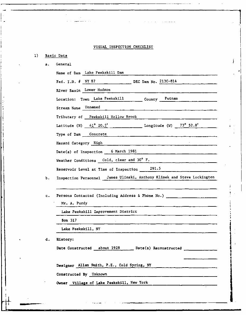
Name of Dam Lake Peekskill Dam 'I
Fed. I.D. # NY 87 DEC Dam No. 213C-814
River Basin Lower Hudson
Location: Town Lake Peekskill County Putnam
Stream Name Unnamed
Tributary of Peekskill Hollow Brook
Latitude (N) 410 20.2' Longitude (W) 730 52.8'
Type of Dam Concrete
Hazard Category High
Date(s) of Inspection 6 March 1981
Weather Conditions Cold, clear and 300 F.
Reservoir Level at Time of Inspection 291.5
b. Inspection Personnel James Ulinski, Anthony Klimek and Steve Lockington
c. Persons Contacted (Including Address & Phone No.)
Mr. A. Purdy
Lake Peekskill Improvement District
Box 317
Lake Peekskill, NY
d. History:
Date Constructed about 1928 Date(s) Reconstructed
Designer Allan Smith, P.E., Cold Spring, NY
Constructed By Unknown
Owner Village of Lake Peekskill, New York
2) Embankment -Not Applicable
a. Characteristics
(1) Embankment Material _________________________
(2) Cutoff Type _____________________________
(3) Impervious Core ___________________________
(4) Internal Drainage System__________ _____________
(5) Miscellaneous ____________________________
b. Crest
(1) Vertical Alignment_________________ __________
(2) Horizontal Alignment______________ ___________
(3) Surface Cracks____________________ ________
(4) Miscellaneous ___________________________
C. Upstream Slope
() Slope (Estimate) (V:H) __________________________I
(2) Undesirable Growth or Debris, Animal Burrows____________
(3) Sloughing, Subsidence, or Depressions _
(4) Slope Protection
(5) Surface Cracks or Movement at Toe
d. Downstream Slope
(1) Slope (Estimate - V:H)
(2) Undesirable Growth or Debris, Animal Burrows
(3) Sloughing, Subsidence or Depressions
(4) Surface Cracks or Movement at Toe
(5) Seepage
(6) External Drainage System (Ditches, Trenches, Blanket)
(7) Condition Around Outlet Structure
_ • I I i •I
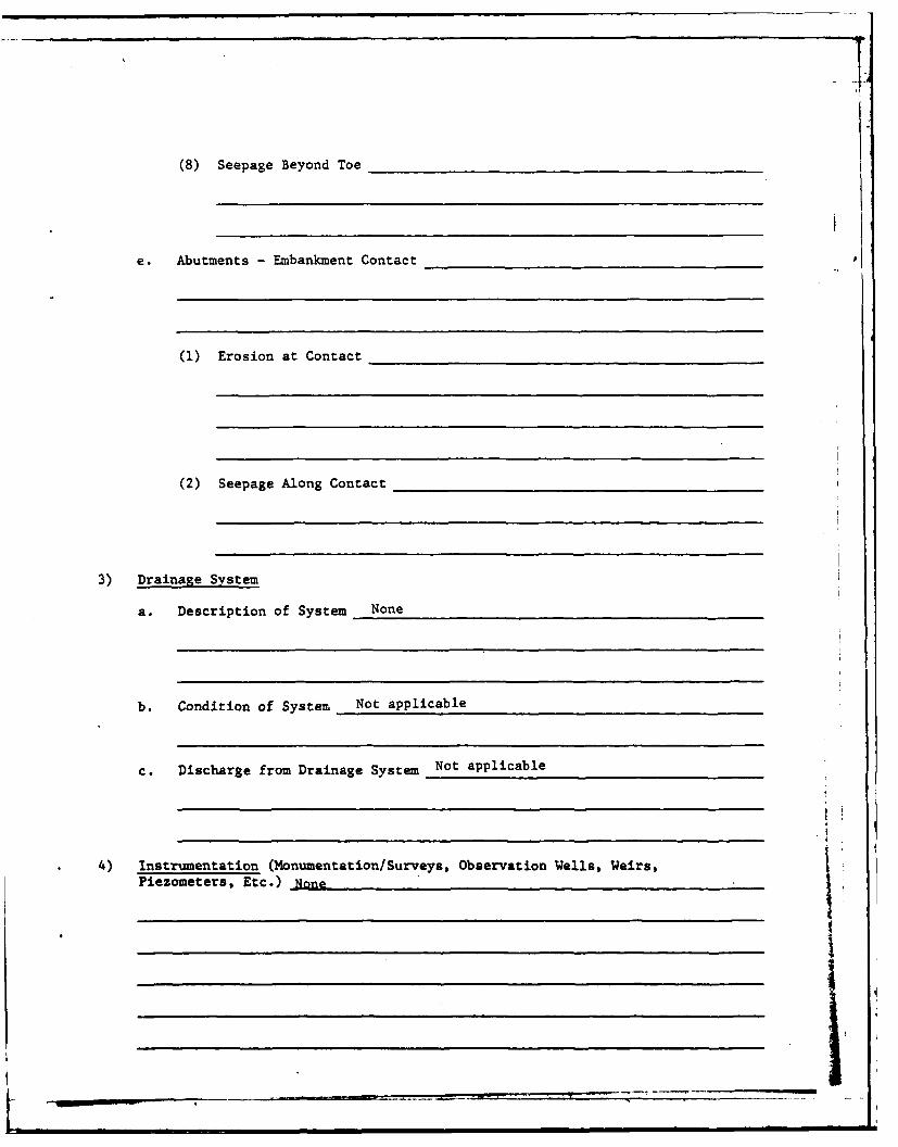
(8) Seepage Beyond Toe
e. Abutments - Embankment Contact
(1) Erosion at Contact
(2) Seepage Along Contact
3) Drainage System
a. Description of System None
b. Condition of System Not applicable
c. Discharge from Drainage System Not applicable
4) Instrumentation (Monumentation/Surveys, Observation Wells, Weirs,Piezometers, Etc.) None II
_______________________________

5) Reservoir
a. Slopes Slopes at reservoir are moderate and developed.
b. Sedimentation Sedimentation is not reported to be a problem.
c. Unusual Conditions Which Affect Dam None observed.
6) Area Downstream of Dam
a. Downstream Hazard (No. of Homes, Highways, etc.) Two homes and a road are
located 1600 ft. downstream. Loss of life in homes is likely if the dam
were to fail.
b. Seepage, Unusual Growth No unusual growth was observed. Seepage near right
downstream buttress near spillway (0.5 gpm, estimated), seep (0.5 gpm) 2 ft.
from far left bridge column support, small seeps on right side bottom.
Erosion from storm sewer downstream of right abutment.
c. Evidence of Movement Beyond Toe of Dam None observed.
d. Condition of Downstream Channel The channel is narrow and steep with rock
outcrops. Structure (8 ft. high and 51 ft. long) is 50 ft. downstream
and is currently breached (non-imvounding).
7) Spillway(s) (Including Discharge Conveyance Channel)
I _ _ _ _ _ _ _ _ _

a. General The spillway consists of two 3 ft. high x 6 ft. wide (perpendicular
to flow) openings which are 4 ft. wide (parallel to flow).
b. Condition of Service Spillway Spillway is in fair condition. Debris found
at the spillway entrance and spillway bottom. Two 6 in. PVC pipes over
spillway are used to siphon water from the lake. Spillway has minor
spalling, -way up face.
c. Condition of Auxiliary Spillway None
d. Condition of Discharge Conveyance Channel Rock outcrops extend the
length of the discharge channel. Debris and trees are located in the
discharge channel.
8) Reservoir Drain/Outlet
Type: Pipe 2 Conduit Other
Material: Concrete Metal Other PVC
Size: 6 inches Length
Invert Elevations: Entrance Unknown
Exit Unknown
Physical Condition (Describe): Unobservable _
_______________________________________________________- I . . i '_-wl: I I I I
rr . .. . _.2 '-I. -- . .._ _-__ _ _• - al

Material: PVC
Joints: Alignment
Structural Integrity: _
Hydraulic Capability:
Means of Control: Gate Valve Uncontrolled
Operation: Operable X Inoperable Other
Present Condition (Describe): Used to syphon water from the
reservoir in fall. Takes one month to lower the reservoir 5 ft.
Broken in places. A 24 in. outlet pipe was plugged with concrete in
1948.
9) Structural
a. Concrete Surfaces Abandoned bridge deck (top of dam) is spalled. Right
downstream buttress is seeping through deteriorated concrete. Far
left downstream bridge (abandoned) support is undermined.
b. Structural Cracking No major cracking.
c. Movement - Horizontal & Vertical Alignment (Settlement) None observed.
d. Junctions with Abutments or Embankments No problems observed.
i

e. Drains - Foundation, Joint, Face None observed.
f. Water Passages, Conduits, Sluices None observed.
g. Seepage or Leakage Seepage exists near right downstream buttress near
spillway and 2 ft. from far left bridge column. The seepage is estimated
at 0.5 gpm. The owner's representative reported seeing seepage exiting
the right toe area near the spillway. The inspection team did not observe
this seepage because of the amount of debris at this location.
h. Joints - Construction, etc. No problems observed.
i. Foundation The dam is estimated to be founded on tight, high RQD
gneissic rock.
J. Abutments No problems observed.
k. Control Gates None A
1. Approach & Outlet Channels Good Condition
m. Energy Dissipators (Plunge Pool, etc.) None
n. Intake Structures None
o. Stability No signs of instability were noted during the visual inspection.
p. Miscellaneous
10) Appurtenant Structures (Power House, Lock, Gatehouse, Other)
a. Description and Condition None
4P-I
APPENDIX C
HYDROLOGIC/HYDRAULIC DATA AND COMPUTATIONS
I
i ....

MICH-AEL BAKER, JR., INC. subSect __0_'F 12F , DAH s.o. No.
TIlE BAKER ENGINEERS APPJF,, X Sheet No.- of
Drawing No.Box 280
Beaver, Pa. 15009 Computed by Checked by Dote
CNAEcX 7"5 FAPA 5.-
H~oluA-ee) AC(htYOV4 JLC 0,47-
TOP OF OAM Pe0,P; Y9
:rP/4CA ,-- 5APC7-11AVAJ
AP.4T/NC- 10A O~ef6 /J.
Arqc- c )ev
"
I
S---_ _--

CHECK LIST FOR DAMSHYDROLOGIC AND HYDRAULIC
ENGINEERING DATA
AREA-CAPACITY DATA:
Elevation Surface Area Storage Capacity(ft.) (acres) (acre-ft.)
1) Top of Dam 295.6 67 1,357
2) Design High Water(Max. Design Pool) Unknown ....
3) Auxiliary SpillwayCrest None ....
4) Pool Level withFlashboards N/A ....
5) Service SpillwayCrest N/A -- 1,074
DISCHARGES
Volume(cfs)
1) Average Daily Unknown
2) Spillway @ Maximum High Water - Top of Dam - 589
3) Spillway @ Design High Water Unknown
4) Spillway @ Auxiliary Spillway Crest Elevation N/A
5) Low Level Outlet N/A
6) Total (of all facilities) @ Maximum High Water 589
7) Maximum Known Flood Unknown
8) At Time of Inspection 15
II

CREST: ELEVATION: 295.6 ft.
Type: Concrete (two 3' X 6' openings)
Width: 16 ft. (abandoned bridge deck) Length: 120 ft.
Spillover Broad-crested weir
Location Spillway is located 25 ft. from left abutment
SPILLWAY:
SERVICE AUXILIARY
291.0 Elevation None
Two broad-crested weirs Type --
4 ft. ea. Width --
Type of Control
Uncontrolled Uncontrolled --
Controlled:
-- Type _-(Flashboards; gate)
-- Number --
-- Size/Length --
Invert Material
Anticipated Lengthof Operating Service
Approximately 12 ft. Chute Length --
11 ft. Height Between Spillway Crest --
& Approach Channel Invert(Weir Flow)
II
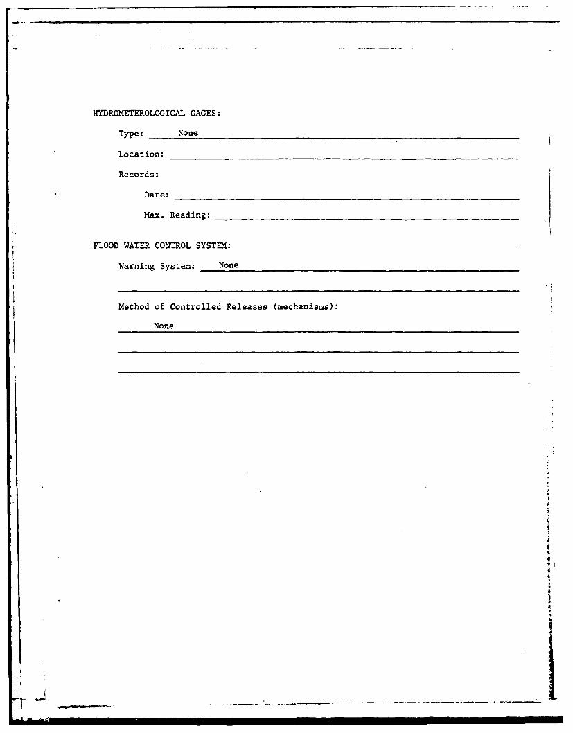
HYDROMETEROLOGICAL GAGES:
Type: None
Location:
Records:
Date:
Max. Reading:
FLOOD WATER CONTROL SYSTEM:
Warning System: None
Method of Controlled Releases (mechanisms):
None
4
a
4
£
LI
, -" II i I I I

DRAINAGE AREA: 0.60 sq. ml. (386 acres)
DRAINAGE BASIN RUNOFF CHARACTERISTICS:
Land Use - Type: Forests and lake development
Terrain - Relief: Moderate slopes
Surface - Soil: Well-drained
Runoff Potential (existing or planned extensive alterations to existingsurface or subsurface conditions)
No known plans to change runoff patterns at time of inspection.
Potential Sedimentation problem areas (natural or man-made; present or future)
No problem areas observed. Slopes were developed or well vegetated.
Potential Backwater problem areas for levels at maximum storage capacityincluding surcharge storage:
Flooding of homes on the lake shoreline could occur.
Dikes - Floodwalls (overflow & non-overflow) - Low reaches along theReservoir perimeter:
Location: None
Elevation:
Reservoir:
Length @ Maximum Pool 3,400 ft.
Length of Shoreline (@ Spillway Crest) 8,800 ft. (1.67 mi.)
|Y
: i i i i •i •I I IIII| II I I
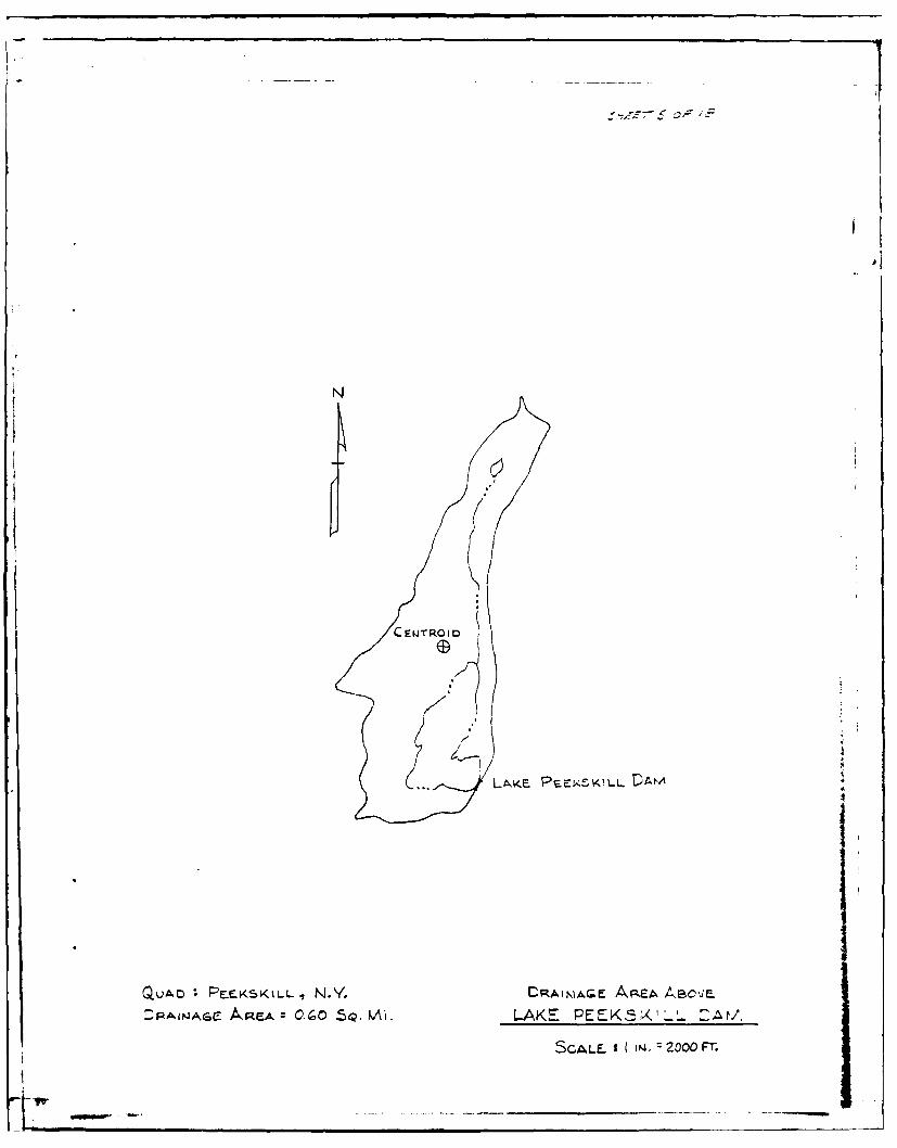
LAE-P EKKI-
QuAD PELFKSKLL,.Y CqAiriAr-e A9pFA 4BC'JF-
D:RAIWAGC kA& CR O SQAI LAK PEEK5X-' :At/,-
SCALE. 1 200 14 Z Fr

MICHAEL BAKER, JR., INC. Subiect IIA') , S.O.-No. . __0. N __.
THE BAKER ENGINEERS Zv. , - , ', Shoot No. 6 of _"_
Drowing No.
Box 280 ~Beaver, Pa. 15009 Computed by - Checked by Date
-- a 5A / = //2' & 34)0 c'= c-7o , . Q ~ ,.
* _ e_4,4 7e ~7c,
z7
1*Pe O,1Z_ /a'- 7?.
.
r (! XZc )o
4L3C Z.o 1 ._3( .7:')
7 -z.i4 /,,

MICHAEL BAKER, JR., INC. Subject Al-r PFE'. _ A2P, S.0. No.
THE BAKER ENGINEERS Sheet No.Z of
Box 280 Drawing No.
Beaver, Pa. 15009 Computed by ..15 / Checked by Dote
ejA~Q)LA~E)7'ce, r=899cl o-
AVE4,eA c- -F E.,E VO/F *i, .2 - C .-e ,/AJ M; 0 gcfr - -'"AA1)
RAo4'5 R077-0o- ,. )- .. ,Qe--OjR
I
II
N
_ I

MICHAEL BAKER. JR., INC. Subject /, ) ~~S. 0. Noa. _____
THE BAK:R ENGINEERS /jW,:_ (k -¢_'"L ,,77 Shet No. '17.of
Drawing No. _
Box 280 Copue byBeaver. Pa. 15009 Computed by Checked by Date ,
77-
Ar

MICHAEL BAKER. JR., INC. Subject k~'f?-kkJ1~S.O. No. ______
THE BAKER ENGINEERS -4 ~Sheot No.2of.40
Box '280 Drawing No. ______
Beaver. Pa. 15009 Computed by -5A'Checked by Dote_____._____
100
:Zj
oak
.C1
rXN

MICHAEL BAKER, JR., INC. Subiect , P'$L, DAP' S.0. No.THE BAKER ENGINEERS CPs.5 c r,'p J A7 1r,. /Z247 Sheet No. /0 of J,
Box 280 Drawing No.
Beaver,. Pa. 15009 Computed by 2Y,, Checked by . Date ZZ&<Z . .
3,05 -
I."Np
44
*4
_ 7,- .o ,9 --

MICHAEL BAKER, JR., INC. Subject Z~PP.~A ? S.D. No. ______
THE BAKER ENGINEERS LIP5TQA/l61 PORYJA.' Sheet No. //of J
Drawing No.__ _____
Box 280Beaver, Pa. 15009 Computed by -Checked by Dote Z/ /
Ci (3
MICHLAEL BAKER. JR., INC. Subject -Atif LAM S.O0. No._______
THlE BAKER ENGINEERS 'P'.Jj II6'~// .7A~~SetN.J f2Ai 4)-Z :L4 rawingSee No. __2__of__/2
Box 280DrwnNo
Beaver, Pa. 15009 Computed by '~ Choecked by ' C" r Dote 2 L.
7,14 7',-1. -'; W_7 ~ej 7 ~ ~ ~~ J
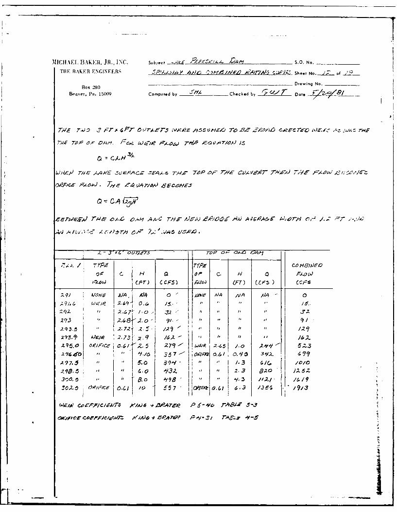
* jFc ; O A4,J . 40 4rlo =~AOW 74.S OVAI.J)
7',14.-- O VTAZ .0,4 AA) AUWY4&'1)Y0-04C"
o'~ C. H Q o C- Ili~e
(F___I~ JT) 6CCP5) )WW (FT) (CF.5 )~ r
;z 9J AIA, ZS9.& f *- 1 A~o- M IV
2% 2,. 8}1.2.0; 9-' " " a
.293. .272 2.S f /,29 -"
293.1' A JE-e 2.73 " z. q 14.- "/ Z
oZ//.4Oz J~FC 2 79 - O 2-6d .5 /.0) A''1 51-3.zlc eo 1~.1 57- ~04M 0,6C) / 0 39Z e
A 97,,5 5.0~ 391 1 /3 4/c, /0/0
6.0 A93. a 3 820
wwEa ~ CoP//W. j& zA47lAR R~ 6-yo rA30-4 , -j
Iw~- cc ,ooAr*3wn 1/3A~e .*-+&7 PA -Z'ir,3

MICHAEL. BAKER, JR., INC. Subject '-A*e- /k/.,- P, S.O. No.
THE BAKER ENGINEERS 5Pi1,/A ,,P,4T ).,, Y,/ Sheet No.Z.Lof
Box 280 Drawing No.
Beaver. Pa. 15009 Computed by 5IA Checked by Date 29--..
77% P"1
75
II.50/
4 ToP oiF /Zfr?
.z5 / I
0 I,1.3 2 9.5 .7 z7
CAVr 1 -OoV ifpr.,
4
II
It|
.- ,..',-.,--,-.
I I
I I IIi
'I
I II * I,.-~
I I
I; jI, I
-'I -
I, I i I II
I~I .L)L;~~,NI~I ii
-II* I
liz: i~~ -~ N 'I
~ e N ~ NP~
I '~ ~ ~5 I
I I - :i-~--~-, Li. I I -~
- .3-' - *-, S., .3
* nt~* NI I V~I 4!NN
* j~, 4 . ' ~1* NI
4
.~.2, 4
*=-*-i*~- 4
* *)ajT~4 I.:ii. *~. )* C- 4* ~ S A ~4 - 94- * It S t C - NJ C It S -. 43~ C - N - .9 it C ~
" ~-------------NNNNNN* ~*~JT**~.4 4~ 4
~ - .
L
I
* I
.
I I
I ' .)
I z: .
... .I"!
... .1-,
i = **
IIi~.
,.J .
I. ... o
_
_ll2-;'J
.. ....
;it.
f
•
-
-
-
" m
i I n m

-i ' '
~I- i
' I -0
S SJ
l--
-I• I I *
-- I '4
• ,I ,, !
"4 I- IJ A4
-,
L-I ' J-I I 'I III I - I I
r I | '2!
I LI F
I I
r I I I
-! F
F I
" 1 :
"- ' '!F
'' F i
- . ,
F -'* Ft

- I
I I j- .JJ
~c I.1'~I i ii
-:
' I
- I J~;
~I~? ~
1 .i...,. I
ZI~2'Z I
~I I
4 I I -
,- ~
-) ~I
T-I ~4*~~3
* I;,
I I
*~.,eI. *~r~L )*..c
I I
* Ii - I* * I I ~. .,*... I I I II
* I
*a.
APPENDIX D
REFERENCES

REFERENCES
1. University of the State of New York, Geology of New York,Education Leaflet 20, 1966.
2. Broughton, John G. and others, "Geologic Map of New York -
Lower Hudson Sheet," New York State Museum and ScienceService, Map and Chart Series No. 15, 1970.
3. Dunbar, Carl 0. and Waage, Karl M., Historical Geology,John Wiley and Sons, Inc., New York, 1969.
4. Putnam County Soil and Water Conservation District,Interim Soils Report Including Inventory and Use Inter-pretations - Putnam County, New York, U.S. Department ofAgriculture, Soil Conservation Service, March 1972.
5. Bureau of Reclamation, U.S. Dept. of the Interior, Designof Small Dams, A Water Resources Technical Publication,1977.
6. Chow, Ven Te, Handbook of Applied Hydrology, McGraw - HillBook Company, New York, 1964.
7. Chow, Ven Te, Open Channel Hydraulics, McGraw - Hill BookCompany, New York, First Edition, 1959.
8. HMR 33, "Seasonal Variations of Probable MaximumPrecipitation, East of the 105th Meridian for Areas 10 to1000 Square Miles and Durations of 6 to 48 Hours," (1956).
9. King, Horace Williams and Brater, Ernest F., Handbook ofHydraulics, Fifth Edition, McGraw - Hill Book Company,New York, 1963.
10. Soil Conservation Service, "National EngineeringHandbook - Section 4, Hydrology," U.S. Department ofAgriculture, 1964.
11. Soil Conservation Service, "National EngineeringHandbook - Section 5, Hydraulics," U.S. Department ofAgriculture.
12. U.S. Army, Hydrological Engineering Center, "FloodHydrograph Package (HEC-1), Dam Safety Investigations,Users Manual," Corps of Engineers, Davis, California,September 1978.
13. U.S. Army, "Inventory of United States Dams," Corps ofEngineers, 9 September 1978.
ii m _ _ __m_ _ _.
14. U.S. Army, Office of the Chief of Engineers, "Appendix D,Recommended Guidelines for Safety Inspection of Dams,"National Program of Inspection of Dams, Volume 1, Corps ofEngineers, Washington, D.C., May 1975.
15. George, Thomas S. and Taylor, Robert S., Hydrologic FloodRouting Model For Lower Hudson River Basin, WaterResources Engineers, Inc., 8001 Forbes Place, Suite 312,Springfield, Virginia, January 1977.
16. U.S. Army, Office of the Chief of Engineers, EngineeringCircular EC-I110-2-163 (Draft Engineering Manual),"Spillway and Freeboard Requirements for Dams,Appendix C, Hydrometeorological Criteria and HyetographEstimates," (August 1975).
17. U.S. Army, Office of the Chief of Engineers, EngineeringCircular EC-1110-2-188, "Engineering and Design,National Program of Inspection of Non-Federal Dams,"Corps of Engineers, Washington, D.C., 30 December 1977.
18. U.S. Army, Office of the Chief of Engineers, EngineerTechnical Letter No. ETL 1110-2-234, "Engineering andDesign, National Program of Inspection of Non-FederalDams, Review of Spillway Adequacy," Corps of Engineers,Washington, D.C., 10 May 1978.
4
II
l a I4

I-I
APPENDIX E
DRAW INGS
I

CONTENTS
Location Plan
Watershed Map
Plate 1: Field Sketch
Plate 2: General Plan from Replacement Bridge Design Drawings
Plate 3: Original Dam Design Profile and Section
4
S
II

LAKE APESILDAMS (Imis IF
.578%7
NN
N/r
~\ I4-
AkP SKL
'A.
SCALE 12400
.0
REFERENCES; OLII. U.S.G.S. 7.5 PEEKSKILL,N.Y.LOAONP N
QUAORANqLE. 1957 LOCATION_____PLAN_1U.3.047.5 MONEGANLAKE,NIC..LK E KL A
QUADRANG0LE. 1956 LK EKKL A
N~t am
LAKE -N- 0PEEKSKILL DAM~,
-ancis
I-! >-e
iA I' ,
-, j4~~I ?'~/~ az~I~v
Cri
(~ I-
-~~~~ At I Z '' ~ -
Dr A
4,, - -
REFERENcEs:I- U.S.G.S. 7.5' PEEXSKILL,N.Y. WAERHE AQUADRANGLE. 1957 WAESEIAZU.S.G.S 7.5'MOHEGAM LAKE,N.Y AEPEKKL AIQUADRANGLE. 19 56 LAK P-KL

4~. 1
L'I
N
-4
Liji
-- 7777,
kc
Road i aw if /V
5U 'Y/
rye. ESTIMATE
* a C41~ 870cf
ta .6a,
It 3~~~~75(4) 5fr ~qvMa'
Ld :A' JhA- Crn
0r.
Ho~eNr t" * .

1 Prej e1 sea' .4
r, ieam4,4S110-r o eF2,,em'60,1
4'.
jee J 2#y .'Va. . AL SECTION-ALTERN
AA t'i
,Y- 10'4w>
Edo____ETMT FQANIIS/en0s£
_____________~~~~ ___ob;1 6 /M.' 'mw
14 C-" IVA-. ". *I v/ A/O P/Lb'- /he A?0 ,;-AO ieca~*EWc rsde . 140 10 TOP 44A
F 500 0
Jf~C/.'. JtY L, - 92 O$fud b.pe Co,700to ovc.-fo I
/qoS"4.2/0 7

- -. IN.
-, rr- --- ,
I ii
N ~1 4 - - -
t --
'7(N 77N ~ 7
-I?--
p ~
77~7-
5~c 7/ON qT .5F'/L 4LW/,'r
F,
- -- .~.. - - - i

T' 4 SOONt
4
_ - VO
- -- -- 'URA
* AC2Wo 6,w V's -L
APPENDIX F
BACKGROUND DOCUMENTS

I
GENERAL BORING'S, INC. STRAITSVILLE RD., PROSPECT, CONN.
ISOILS CLASSIFICATION SYSTEM
DESCRIPTION FROM TO
BOULDERS 8" +
COBBLES 2-1/2 8"
COARSE GRAVEL 1" 2-1/2
MEDIUM GRAVEL 318" 1"
FINE GRAVEL 2mm 318"
COARSE SAND 0.5mm 2mm
MEDIUM SAND 0.25mm 0.5mm
FINE SAND .125 0.25mm
VERY FINE SAND 0.62 .125
SILT &.CLAY Less than 0.62mm
Proportions Used -
Trace 0 to 10% Little 10 to 20% Some 20 to 35% and 35 to 50%
EXAMPLES -
"Brown fine sand ) Equal amounts of sandMedium gravel" ) and gravel
)"Brown medium to ) Sample predominantly sand
fine sand and gravel ) with 35 to 50% gravel)
Some silt ) 20 to 35% silt
Boulders" ) Various percentages -

, NERAL BORING'S, INC. STRAITSVILLE RD., PROSPECT, CONN.
CORRELATION CHART
PENETRATION RESISTANCE & SOIL PROPERTIES, I
Predominant sand and gravel I Predominant slit and clay
COHESIONLESS SOILS II COHESIVE SOILS COMPRESSIVEIIBlows per foot Relative Density Blows per foot Consistency Strength (qu*)
0 to 4 very loose 0 to 2 very soft below .254 to 10 loose 2 to 4 soft .25 to .50
10 to 30 medium 4 to 8 medium .50 to 1.030 to 50 dense 8 to 15 stiff 1 to 2over 50 very dense I 15 to 30 very stiff 2 to 4
over 30 hard over 4I I
NOTES:Above based on 2" 0. D. sampler x 1-3/8" i.d. 140# Wt. x 30" Fall (qu*) =Tons per Square Foot
STATE OF CONNECTICUT BASIC BUILDING CODE
TABLE 15. PRESUMPTIVE SURFACE BEARING VALUES OF FOUNDATION MATERIALS
Tons perCLASS OF MATERIAL Square Foot
1 Massive crystalline bed rock including granite, diorite, gneiss, trap rock hard
limestone and dolomite. 100
2 Foliated rock including bedded limestone, ,chist and slate in sound condition. 40
3 Sedimentary rock including hardshales, sandstones, and thoroughly cemented conglomerates. 25
4 Soft or broken bed rock (excluding shale) and soft limestone. 10
5 Compacted, partially cemented graveis, sand and hardpan overlying rock. 10
6 Gravel and sand-gravel mixtures. 6
7 Loose gravel, hard dry clay, compact coarse sand, and soft shales. 4
8 Loose, coarse sand and sind-gravel mixtures and compact fine sand (confined). 3
9 Loose medium sand t-ofined), stiff clay. 2
10 Soft broken shale, soft clay. 1.5
- . .- ... ..I

General Borings, Inc. Sheet__ of__
STRAITSVILLE ROAD PROSPECT. CONN. iC712
REPORT OF AUGER BORINGS AND PIPE AND BAR PROBINGS
TOWN -2utna" 'Jalley LINE 3,,?1io 14+C,6
PROJECTNAME r-c-kskill lalke Eridive PROJECT NO- ',-
FOREMAN R. Tucil DATE WORK DONEK
DISPECTOR W. C' Ireska FOR Goodkind & C'DnaCONTRACTING ENGINEER
Offset (Ft.) Depth Soil Strata (Inc lude: Groundwater depth, Size of)
Station From From Probed inAuger Holes Remarks (Auger used, Description of Soil in)B C (Ft.) Frm To (Auger Holes, D~epth of Auger Samples)L L (Ft.)(F.
SOUTDING
______Drove rod 6'7"
Gmeral Borings, Inc. SMERT__!_. OF_7...CLINr ocakL"U0 &'~Z~ . ?'-aI RAITMVILLE RD. PROSPECT. CONN. MOLE 00 S-.
COT O - PROJECT NAME 101
_Ppekskill Lake, BridpP _11+__ _6
[MAN -DRILLER LOCATION STATION
R. Tuccillo Putna- County__INSPECTOR
'. 1< =v r"! __________________
GROUND WATER OSSERVATIONS ,.., TA"Nco CO..L ,,,lzl/l/E%., F./1/6 //AT L AFTER---"ouas SiZE 1.0 i_ _ $UNP3ACK 9Lv92 .I
AT- FT AFTER HOURS HAMMR :T 140 Did'ond &@UN wATt, EL-v.ASIN ,T - -T- -. DEPTH AMMER FALL 3&.casing SAMPLE tOWS PER 6, CONINS DENSITy STRATA
0 SLOWS ON SAMPLER TIME OR CHANGE FIELD 10ENTIFICATION Of SOIL
PER No. TYPE PEN ftc DEPTH (FORCE ON TUIE) PER FT CONSIST DEPTH REMARKI INCL. COLOR. LOSS OFo FOOT L ICy |MOS.L WASH WATER, SEAMS IN ROCR. ETC.q)'t~0 I*| UIST ILCv
s 2"I 7 ) Brown coarsP-fine sanr,
so-e silt, trace-ed-finFt usain gravel, trace root -aterialRef'usal 41 L,011 6"1.
1 'arbide2 3 61 Run#l Drillld 4'C"-60".-- 7 Recovered Q'-7" fracturn-4 7Di -ond greenish gray rock(soft).
5 1 b Rur.#6 -12 I'C' Rur#2 Drilled 6'0I iI.
,o7 - .....--.. Recovered 2'1I0" greenish- -- 9gray gneiss. Vertical and
horizontal sea-.(-- - fractured)
Run#'_2 ' 0_Run#3 Drilled 10'0"-12 1
Recovered 1'5" greenishgray gneiss.
- -END OF BORING
12'
- 4' Soil
25-- 8' Rock
30--
35-
TYPE OF SAMPLES TOTAL POOTASE
D R W. WASDN C CORE A AIee n Vpsy IS V 4iTUA5iE t PT AtOl OO TAGE
@A1U.O1.URO SAL CHECO V18VA&E TESTROCK cOm"41-mT.
PRO@OI41O6s USED TRACE * 10%. LITTLE I IO-2WO SOME * 50-55%, ANS* a -s0%
IL I

General Borings, Inc. sM[[T .. L__oF. LCLiENT:..0c oo _.. d C " STRAITSVILLE MO. PROSPECT. CONN. HOLE NO..2,--
CONTRACTOR -OJCT N" E L I
Lake Feekskill, Bridge QlMAX -OILLER LOCATION ITATION
Putnar Count,! 11+76INSPECTOR OFFSET
'Y. Cre s' New Vork _, __,
AROUNo WATER OSEVATIONS TYpE AL.9 o . _FT AFTER HOURS SIZE I.. __ 3 SURFACE gLEV.9 2 • 4
.A.MER WT ____ Diamrond &,"AMMER WYALL7 ViaYon & $BOUND WATER £tLgV.AT- -T AFTER NOUN$ "AMMR FALL it -
CASING SAMPLE SLOWS PER 6" CORING DENSITY STRATA FIlLS IDENTIFICATION OF SOILSLOWS - EPTN ON SAMPLER TIME OR CHANGEPERN NO. TYPE PEN DEC * I FO1CE ON TUBE) PIER FT CONSIST DEPTH NEMARKS INCL COLOR. LOSS OF
- o .-OT (MIN.) WASH WATE0, SEAS IN ROCKE, ETC.o OT4 O - P -* 11, 0I CLEV
i__ 1 ss '61II' 6 T 1.2 ' 1) Brown coarse-fino sarn,
Ft. Lin, little silt, trace -Ad-F.-1 -4.11 fine gravel.1 4 _ _2 4 Run#] Rurn#l Drillod 3'7"-7,'7"3 5 5 1 7" Recovered 0.7' greenish4 6 gray rock(fractured).5 6
6 4 1 Run#' Run#2 Drilled 5'7"ll".
10 7 6 1-l'l" Recovered 11" greenish9 6 gray soft rock.
_____ 9 8___
Lo I0 Run#3 Lost water at 7'6".L1 10 13'7" Seam 8'ii"-9,6".2 4
"3 4 Run#4 Run#3 Drilled 10'l"-13'7".L4 5 14'7 Recovered 2'4" greenish- 6 Run# gray gneiss.
20 -- 18'7" Water returned at 1017".20
Run#4 Drilled 13'7"-147".Recovered 0'-5" sea-yfractured greenish gray
2 --- gneiss.
Run#5 Drilled 14'7"-18'7".Recoverod 2.0' greenishgray gneiss.
30- -- -D CF BCRING• - 181'7"1
3171 Soil151011 Rock35-
TYPE OF SA~MLIS TOTAL FOOTAGIE
OR W WASH S CCOnS A AUv c UP umarnISTU* E ls PIetON
UsUNOISlIIrOE SILL CHECK VT1VANE TESTmRROOC GOIN0 LS0 . 0.
pePeoriOns Use* TRACC - O0- 10%, LITTLE 1 10-o0 $o111C ao O- 3e$%. Aloe 35 - 60%

cuwrG.fkird CI- c' General Borings, Inc. S3EET .. OF. Io
I IrRAITSVILLE RD. PROSIPECT. CONN. HOLE -S-3
COMYRACTO P JECT NAME L,,CIakP Peekskill, Bridge d 12+56
MAN -ORILLER LOCATION TATI0ON
R. Tuccillo Putna- Count;1INSlPCTOR XT f %iIk P, o l OFFST 18 1
CASING SAMPLER CORE SAN$NOUNS, WAVIER OSERVATIONIS VgqA qAX Ds-iLL-D.- 13162T _ , o. ____,,oums ,.e ..AL__ .. .g.JC/31 .. FI-O/3l/.
AT A _ _ " R oil I SURFACE ELEV. 90.0iT..-.. F....4..__ T AFTER - H : * Dia ond GROUND WATER CLEV
HT_ IT &T' _ 1OURS HAMMERN FALL ________________
Z-ASN SAMPLC SLOWS pERt 4" CORING DENSIT" STRATA FIELD ISEMITIFICATION OP $OILSLOWS 00 SAMPLIE1 TIME on CHANG
C:f* NO TYPEPN * C I FORCE ON TUICI PER FT CONSIST ORPTH REMARKS INCL. COLOR, LOSS OF
a-6 1-I l-IT MOIST LOTV WASH WATER, SCAMS jiU NOK. Trc.
1 ss It"12" 3 6 11 1) Brown coarse -1n7 sa.d ,Ft_ _-in little silt, trace coarse-
Refusal 3' fine gravel. 0t6-15".
2 2 Run#1 Run#I Drilled 3 01-61 C"3 2 61 Recovered 0 '-2" greenh4 2 - gray rock (soft).5 2 Run#2
6 2 9' Run#2 Drilled 601-9101.!1 7 2 Recovered i7"1 greenish
gray rock--soft-fracturedand sea-y.
__un#3 Run#3 Drilled 9'1-1113".
_11_ Recovered C'-lC" quartz wi, ___greenish gray sea-s.
_END OF BORING
0 -o_ 3' Soil
81 Rock
25
30-
35-
TYPE Of SAMPLitS TOTAL FOOTAGE
. o v A SHO CC Ono AAUV I0 UPSo NDMISTU48E PIston ARTH in INwi rG- ".
,US URSlSTUNDiS @ALL CHECK vToVARK fat
-PRli TIlORIS Uses TRACE a OIO%. LITTLE e 10-201 SOME IO'0l55% Als, 555so%
C t.odkird CDea General Borings, Inc. sWEET _.._1 OF 1-n STRAITIMLLE RD. PROSPECT. CONN. HOLE NO. -
CONTRACTOR PROJECT NAME LINelake Peekskill, Brid-Pe 0 12+56
EMAm -DORILLER LOCATION STAT IO
R. "UCCILIC Putna- County_!NSPECTOR OFFSET
W. Cereska New York 14'"CASINO SAMPLER C LAR
2GRONDWTE OBEVAIN SIPE IDm ______qi.F. 1AT2.. 61' F, AFTER C_ "_URLa SIZE ..oL SURFACE ELEV. 02.AT - T AFTER - HOURS__ HOU SMER FALL D ial "'nd SISU N WATER ELEV
CASING SAMPLE BLOWS PER I" COsINO DENSITY STRAT- F19LO IDENTIFICATION Of SOIL1 SLOW$ Of SAMPLES Time on C04ANGE ~ IETFCTO ~SI
DEPTH REMARKS INCL. COLOR. LOSS OFS PER . Type PEN NEC 1Om(cg ON TUBE) PER FT CONSIST OEfo.NSFOOT I 1 O - - (MIN.) - - WASH WATER SEAMS IN ROCK, ETC.
1 1__ 61 ~ 2'... 1) Brown coarse-fine sand,____ -- - -little coarse-fine gravel,
little silt. O.C'-1'6".2 1" 4"-'C" 13 3T 311" 2) Gray-brown coarse-fin"5-- F t .,,in 161" sand and silt, trace -ed-
_ A 1 3_ 311 1' 1 2 -fine gravel. 51011-61011
2 2 Run#1 2A) Greenish gray soft
3- 3 86" deco-posed rock. 6'0"-6'3"
5 2 Run#l Drilled 6'6"-5'6".
6 2 Recovered 0'-4" greenish7 3 gray rockfrag-ents.
Run#21- 1 -0-'6" Run#2 8'6"I-lOI6"I(drilled).
RPcovered C'-5" greenish
gray rock fragMents.
- -- -- -un#3
20 !I'6" Run#3 Drilled i0'6"-13'6"Recovered i'6" greenishgray rock.
25 - SEIM OF BCRING
13'6"
6'6" Soil
7'0" Rock30--
35--
TYPE OF SAMPLES TOTAL POOTAGE
. 9Y W.W IAINS Co COR SO aa & v eO R MP aUSY ISTUROEO PIsto n S I SUIMN4h-- .
US UNOISTURBOED ALL CNECI V TIVAN TIST
PROOTIONS USED TRACE - O-O%, LITTLEo IO1 O SOME tO*30- %. ANOV *-0
II
APPENDIX G
STABILITY COMPUTATIONS
I
71-.

MICHAEL BAKER, JR., INC. Subject Z4 e '" - s.0. No./ ' : ) -/61THE BAKER ENGINEERS ,-___ ,! ___"-____,___,____Shoot No._ .._ of
Box 280 Drawing No.
Beaver, Pa. 1S009 Computed by -Checked by s'L &( O /ate / //I:x
r(
___________ _ __ s/ I /~
-I7I
/,< 0 I
I "
Zlf. 7,,ff- /jp"' 710(-_ _ _ _ _ _ _ ,! - - Z
112 /0_27
1/
a / b1-' I7
7 1; '' 4' / /-*- y -:.'"-.''$ ¢ ... - . . - ,,
77 !kF*A
MICHAEL BAKER, JR., INC. Subject 4A/o " . S.O. No. )
THE BAKER ENGINEERS Shot No. of
Box 280 Drawing No.
Beaver, Pa. 15009 Computed by ' Checked by "Date '
J/... I'
21
'2 7-
S "/,- /A Z

/'
MICHAEL BAKER, JR., INC. Subject S" /0. N a.
THE BAKER ENGINEERS .Shot No.-O-ef.
Drawing No.
Box 0-80Beaver, Pa. 15009 Compute.d by Y!/ .< by J' Date /1, //Co/dy
(nii<..--
-7-7
73.
IC;
/.as- At),
ir-A
-V -
MICHAEL BAKER, JR., INC. Subject 4*S,?", /, ,.o. No. ' - . -,2,J'_THE BAKER ENGINEERS 4/".~., ~ ~ ,N.___o
- Soo No -/Box 280 Drawing No.
Beaver,. Pa. 15009 Computed by Z Chocked by Date * /4 /74"
7ZI
-
7- -w 7. 7f
kk
6&//0I I /S7/?'
_ _ _ _ _ _ _ _ _ _ _ _ _ _ _ __z_5_ _ _ _
X~lyp

MICHAEL BAKER, JR., INC. Subject /. -' S.O. No./(' 9 . - - 6t
THE BAKER ENGINEERS 0-A'/ ho N.__ f.~
Box 280 Drawing No.
Beaver, Pa. 15009 Computed by Checked by D~ ate /~/~
"t ' . _ . , -.,,/! J,"'
/ o "____ 7,6,,..> /,'o
2. •
i,. //t- , /. ) /,/ oY: ±: .~ (/ / -*
7-Y
-7 -- ~ .<r 4 r
~.07
1is Ff
MICHAEL BAKER, JR., INC. Subijct : S.o. N __, ______-
THE BAKER ENGINEERS hoo ,t N.t.,, of
__ ___Drawing No.Box 280
Beaver, Pa. 15009 Computed by 6 ih. Checked by " Date " " / //
-._ =/2 s- S-) ,. 33 2s/ ,.o71( X-)
VA/ Tllell*) / ;7,9- $) 7
if/
'-I
1 s- --.
., /,'It
2..
---j c..JI #"
X) I i.. .

MICHAEL BAKER, JR., INC. Subject ''. " ' ,. No.THE BAKER ENGINEERS of-. / r
';/ J Sheet NO. 7 of
Box 280 Drawing No.
Beaver, Pa. 15009 Computed by _)dI/ Checked by 0'2"/i Date //A/, // ',C/
l"2
C-,
" '" - '7' (9K-.3Y )Aw ' -
/ , 2 i , /,'2
Jc .; " $7 1,el
• .' " : , () &.K zs,) : :,¢.
--L5
' '-- -q- - - ".. . .-....AM =a:-. . .... . . . .. . .
MICHAEL BAKER, JR., INC. Subject ' ,. . P"" 0/ /, S.C. No./ - .'9i 0 -) -g&"
THE BAKER ENGINEERS F ,, __o __
Drawing No.Box, 280 c\ljj JN
Beave, Pa. 15009 Comput, by %,/ Checf.,/ by Dole - 4/ 1 /
'-/
744
w ? - = /_.__ -____.__ _ ._ _ _._, _ ___) -1 ._/_ _ , _,<,_
. ,, .:,~~~2S,-, , ,;J
. , //47;
/. (/ . -~o: - :. ). ')17".1?

\lICIxIV BAKER. JR.. INC. Subject S. 0 . . -Til. XkE ENGINEERS , /'/ ,;/- Sheet No.-? of
Ilo \ 28! Drawing No.
H.a' .r. Pa. 1500OQ Computed by Checked by Dote 'A4 c'12___
SJ
/7 /
Co7 CoT
-. -/,97F: r
ei
-/cl -, /5y(C /s- t.'-s'zro )' t,67) Iz - &:',<7 (/,-r,7) -(c'/( '.9):
I .o -/, -~ s.1 "
$E7'
f r7)
-- /2.W(-Sn Ozb " s-,&, "'4 ~ -i:
_ _ _ _ _ _
.1i

DAT
FILMEI
ISI