AD-A124 THE PERFORMANCE MEASUREMENT OF A RELATIONAL ... · AD-A124 919 THE PERFORMANCE MEASUREMENT...
149
AD-A124 919 THE PERFORMANCE MEASUREMENT OF A RELATIONAL DATABASE 1/2 SYSTEM USING MONITOR..(U) AIR FORCE INST OF TECH WRIGHT-PATERSON AFB OH SCHOOL OF ENGI.. G L SNYDER UNCLASSIFIED 15 DEC 82 AFIT/GCS/EE/233 F/G 912 .NIL Emmmmhmmmmmm IIIIIEIIIIEEI EIIIIIIIIEIIEE
Transcript of AD-A124 THE PERFORMANCE MEASUREMENT OF A RELATIONAL ... · AD-A124 919 THE PERFORMANCE MEASUREMENT...

AD-A124 919 THE PERFORMANCE MEASUREMENT OF A RELATIONAL DATABASE 1/2SYSTEM USING MONITOR..(U) AIR FORCE INST OF TECHWRIGHT-PATERSON AFB OH SCHOOL OF ENGI.. G L SNYDER
UNCLASSIFIED 15 DEC 82 AFIT/GCS/EE/233 F/G 912 .NIL
EmmmmhmmmmmmIIIIIEIIIIEEIEIIIIIIIIEIIEE
1.0
1.1.
$ MICROCOPY RESOLUTION TEST CHART
NATION4AL BUREAU OF STANDARDS- 1963-A

3b®r

AFIT/GCS/EE/82-33
Aossolen For
stis am*&Ioun.ed 0Justifioation
Distribution/ OfAvailability Codes *&Dfo'
jkvail and/orlot Special
THE PERFORMANCE MEASUREMENT OF A
RELATIONAL DATABASE SYSTEM USING
MONITORING AND MODELING TECHNIQUES
THESIS
AFIT/GCS/EE/82 Gary L. SnyderCapt USAF
Approved for public release; distribution unlimited.
..... ..

AFIT/GCS/EE/82D-33
THE PERFORMANCE MEASUREMENT OF A RELATIONAL DATABASE SYSTEM
USING MONITORING AND MODELING TECHNIQUES
THESIS
Presented to the Faculty of the School of Engineering
of the Air Force Institute of Technology
Air University (ATC)
In Partial Fulfillment of the
Requirements of the Degree of
Master of Science
by
Gary L. Snyder
Capt USAF
Graduate Information Systems
15 December 1982
K!

PREFACE
Relational databases are steadily moving toward the
forefront of the management information arena. These
databases carry with them many advantages over their
existing predecessors, but one criticism seems to be
continually associated with them - the excessive amount of
time required to perform data retrieval.
Studies have been conducted to attempt to decrease
the amount of time required by a relational database to
perform a given retrieval. One of the more notable ones was
undertaken by Dr. John Miles Smith while a faculty member
at the University of Utah. Smith proposed several
optimization techniques which, when applied to an existing
parse tree of relational algebra operators, would
theoretically decrease the amount of time required to
perform the original query.
Shortly after these techniques were published, an Air
Force Institute of Technology student, Lt. Mark Roth,
began the development of a microprocessor-based pedagogical
relational database, centering much of his effort on
incorporating the Smith optimization techniques within his
system design. This course of action was noteworthy,
because while the optimization methods seemed productive,
they had never actually been implemented in an operational
database.
ii

Dr. Thomas Hartrumv faculty member of the
Electrical Engineering Department, suggested that
the design and implementation of a software monitor which
would analyze the effectiveness of these optimization
techniques be undertaken as a master's degree thesis topic.
I accepted this challenger fully intending to complete the
monitor and provide conclusive and informative results.
However, due to the status of the actual implementation of
the Roth database and insurmountable storage limitations
encountered, experimental results were not obtainable.
Instead, it was agreed that the monitor would be designed,
coded, and tested, and that modeling the system using a
high order simulation language would be explored as an
alternative means of analysis.
This thesis effort has provided an exceptional
learning opportunity for me. I have gained great insight
into the fields of relational databases, microprocessors,
and relational algebra query optimization techniques alike.
Sincere gratitude goes forth to my advisor, Dr. Hartrum, as
well as to my committee members, Dr. Henry Potoczny of the
AFIT Mathematics Department and Major Michael Varrieur of
the Engineering Department. Thanks also must be given to
the AFIT/ENE technicians, especially Mr. Dan Zambon, for
keeping the LSI-11 systems operational. Finally, deepest
appreciation goes to my wife Linda and to my two
children Chris and Kelly for their undying support.

4 CONTENTS
PREFACE . . . . . .. .. .. .. .. .. ... .. ..... ii
LIST OF FIGURES. ............. . . . . ... . vi
ABSTRACT . .. .. .. .. .. .. .. .. ... .... . vii
I. INTRODUCTION .. ........... ... ... 1
BACKGROUND.................... 1STATEMENT OF PROBLEM .. ............ 8GENERAL APPROACH .................. 8SCOPE.......................10SEQUENCE OF PRESENTATION. ............. 11
II. OVERVIEW OF THE ROTH OPTIMIZATION LOGIC . . . . . 13
BACKGROUND . .. .. .. .. .. .... . . . . . 13OPTIMIZATION MODULES. ............... 16SUMMARY......................22
III. RELATIONAL DBMS PERFORMANCE ANALYSIS: REQUIREMENTS 214
OVERVIEW ...................... 24PERFORMANCE MEASUREMENT. .. ............ 26MONITORING VS MODELING. .............. 36SUMMARY. ...................... 39
IV. PERFORMANCE MONITOR. ................. 40
SYSTEM OVERVIEW .................... 40EXTERNAL SUBROUTINE. ................. 42CALLING THE MONITOR. ................ 49HOST-SUBROUTINE INTERFACE . . . . .. .. .. .... 51PROCESSING THE MONITOR RESULTS ........... 54MONITOR OVERHEAD....... ... .. .. .. .. .. . 56DATA REDUCTION AND VERIFICATION .. . . . . . . . 60
V. MODELING THE ROTH OPTIMIZATION LOGIC .. ......... 65
BACKGROUND .......................... .. .65
PURPOSE OF THE ROTH*MODEL......... ....... 69SYSTEM BOUNDARIES. .. ....... .. ..... 70LEVELS OF MODELING DETAIL.... . .. .. .. .. 70
LEVEL I . . .. .. .. .. .. ...... . 71LEVEL II . .. .. .. .. .. . .. .. . .73ISYSTEM PERFORMANCE MEASURES .......... 77
DEFINE ALTERNATIVES, EXPERIMENT, AND IMPLEMENT 78jSUMMARY . . . . . . . . . . . . . .. .. .. .... 79
~wi iv
M- -.---

soft"---- ..
VI. CONCLUSION . . ......... . . . . . . . . 80
SUMMARY ........... 80~~RECOMMENDATIONS[ . . . .. . . . 84
FINAL COMMENT....... . . . . . . . . . . . 85
BIBLIOGRAPHY ........ .................... . . 86
APPENDIX A : ROTH OPTIMIZATION LOGIC MODEL -SLAM NETWORK DIAGRAMS ........... . 88
APPENDIX B : BENCHMARK QUERIES . . . . . . . . . . . . . 102
OVERVIEW . . . . . . . . . . . . . .. . . . . . 102QUERIES .................... . 102
APPENDIX C : CONSTRUCTING THE MONITOR SYSTEM ...... . 107
OVERVIEW. . ................... 107COMPILATION ................... 107LIBRARIAN. ................... 108BUILDING THE SYSTEM ..............LINKER ......... .................. . . . 114
APPENDIX D : DATA REDUCTION PROGRAM - PROGRAM ANALYZE,. 119
APPENDIX E PUBLISHABLE APPENDIX ............... .. 122
I

List of Figures
1. Roth Relational Database Design . . . . . . . . . . . 162. Roth Optimization Modules . . . . . . .. .. .. ... 173. Squiral Optimization Modules. .. .......... 184. Perfomance Measurement Level I. .. ......... 315. Performance Measurement Level II . .. .. .. .. .. 336. External Subroutine . . . . .. .. .. .. . .. . .*47. Calling the Monitor. .. .. ....... . .. . .. 508. Unit Common .. .. ................. . 529. Procedure PRINTMON. .. ............... 5510. Calling PRINTMON . . . .. .. .. .. .. .. .. . 5711. Monitor Results . . . . .. .. .. .. .. .. ... 5712. Monitor Overhead .. .. .......... ..... 5913. The Modeling Process ..... . . . . . . . . . . 67
*14. Level I Overview. .. .............. .. 72
vi

ABSTRACT
An investigation was conducted to provide a
productive means of measuring the effectiveness of a
collection of untested relational algebra query
optimization techniques which are integrated within an
existing microprocessor-resident relational database.
As a result of this research, two methods of
performance measurement were proposed. A software monitor
was designed, coded, and tested specifically to determine
if the employed optimization methods actually decrease the
amount of processing time required to execute a given
query. Additionally, a baseline simulation model was
designed and presented as an alternative means of analyzing
the performance of this optimization logic.
vii
,,- .ia':: .......... . . . . . . . . . . . . . . .

II
THE PERFORMANCE MEASUREMENT OF A RELATIONAL DATABASE SYSTEM
USING MONITORING AND MODELING TECHNIQUES
I INTRODUCTION
BACKGROUND
The computerized Management Information System (MIS)
has evolved into an integral part of contemporary life;
its effect on society as we know it is simply astounding.
Nearly everyone is touched in one way or another by
- automated data management systems..Until recently, a typical database was one of two
types: either a "hierarchical" database or a "network"
database, each drawing its name from the information
structures and the means of data management employed. Then,
in the late 1960's, E. F. Codd began working with a
relatively new form of mathematics called "relational
mathematics", consisting of "relational algebra" and
"relational calculus". Relational mathematics permitted
transactions on interrelated data by introducing a unique
group of relational operators which could be used to
manipulate these sets of information.
In the mid-1970's, a third type of computerized
Sdatabase was subsequently developed based on the
databse baed th

principles of relational mathematics, appropriately called
the "relational database". Relational databases
characteristically provide more simplicity, data
independence, and human-friendliness than hierarchical or
network databases. For these reasons, relational databases
are often heralded as the "information systems of the
future".
Although the relational database offers several
advantages over hierarchical and network models, the
management information community has expressed disapproval
over one of its traits: current implementations of
relational databases using existing architectures are slow
and inefficient. Because data retrieval and manipulation
is, after all, the underlying function of an information
system, the speed and efficiency with which this iata is
managed is of utmost concern; thus the criticism of
inefficiency levied on the relational database is a notable
one,
In 1979, an Air Force Institute of Technology
graduate student named Lt. Mark Roth set out to design,
code, and implement a pedagogical relational database on a
microcomputer system in the AFIT Digital Engineering
Laboratory. Roth placed great emphasis on maxirizing the
data handling efficiency of his manipulation language;
accordingly, he decided to incorporate two techniques in an
attempt to improve data management performance. The first
technique was inspired by a paper written by Theo Haerder
2.
Sr

(Ref. 4). Haerder suggests combining a link structure which
relates tuples of one relation to tuples of another to
provide efficient retrieval with an image structure which
gives ordering and associative access by attributes to
provide efficient updates. Roth went on to discover that an
image can be implemented and maintained through the use of
a multipaged index structure containing pointers to the
relation tuples. Furthermore, the pages of one of these
indexes could be organized into a balanced structure using
the concept of B*-trees (pronounced B-star).
The second technique Roth embodied in his database,
and the one directly addressed by this thesis, may be
described as an "automatic query optimizer interface",
which logically resides between a user's set of relational
algebra query commands and the data residing in the system.
This interface, inspired by an article written by Dr. John
Miles Smith and Philip Yen-Tang Chang in the 1975
Communications of the ACM (Ref. IL, hereafter referred to
as the Smith & Chang article), takes any set of relational
algebra commands entered by a database user, and optimizes
them, such that no matter how inefficiently the original
commands were constructed, they would be executed using the
least amount of processing time possible. Consequently, it
was hoped, even the most inexperienced database user would
see results in the minimum required time.
Because of time constraints, much of the logic
responsible for query optimization in the Roth database is
3

not yet operational. In addition, correspondence with Dr.
John Miles Smith, the author of the paper upon which
Roth's optimization techniques were based, ;Yidicates that
these methods were only attempted in one other Data Base
Management System, and that project was subsequently
abandoned. Consequently, it appears, this specific effort
at improving the underlying problem of relational database
inefficiency is still largely conceptual.
Due to the untested nature of these optimization
ideas, a fundamental question immediately arises. I is
not known if these optimization techniques really
optimize. It is conceivable that more overhead is required
to optimize than would have been required to execute
certain types of initial command files; i.e., obvious
situations may exist (characterized by specific command
file size, operator type mix, relation sizes, number of
relations involved, etc.) for which the execution of
optimization logic is counterproductive. Because of the
interest currently placed on relational databases,I attempts at improving execution speed will become
increasingly important. Query optimization at the
conceptual level is a strong contender as a primary means
of achieving this improvement; thus answers to the
questions raised against the Roth database could prove
beneficial to database designers for years to come.
As the Roth database system approaches completion,
there are two apparent means of determining how
4

successfully it is performing; i.e., determining whether
* the optimization techniques are of merit and whether there
are any other possible areas of inefficiency which could be
improved. One method of evaluation would be to model the
execution of the Data Manipulation Language. By using a
system modeling technique, one could represent the Roth
optimization logic as an operational data manipulation
system. Various parametric changes could subsequently point
out the effect that different structures, e.g., command
file size, operator mix, etc., have on overall execution
time. By employing existing simulation language
capabilities, the time duration of key PASCAL procedures
could be modeled as functions of critical Roth database
characteristics.
A system model can either be a simulation model or an
analytic model. A simulation model reproduces the behavior
of the system, in turn establishing a correspondence
between the model and the system itself. Simulation models
are characterized by states, or the values of given system
parameters at a specified time, t, and transitions, the
variations of parameter values from state to state. These
state transitions are commonly referred to as events, and a
system which evolves from predominantly discontinuous
events is called a discrete event system. While a system
can be simulated using any computer language, including
PASCAL, numerous simulation languages specifically designed
to model system events currently exist, such as SLAM,
5
SLAMII, QGERT, and SCERT. SLAMII, developed by Pritsker and
Associates (Ref. 13) and supported by AFIT resources,
provides an excellent capability for modeling the Roth
optimization logic.
In addition to simulation models, a system may be
represented as a series of mathematical equations. Such a
model is called an analytic model. An analytic model may be
one of two types, depending on the characteristics of its
parameters. If all system variables are predetermined, the
model is deterministic; if at least one system variable is
random, the model is probabilistic. Probabalistic models
are commonly either queueing models, in which a system is
represented as queues and activities fed by these queues,
or Markov models, which specifies statistical relationships
between states in the form of a transition-probability
matrix. Analytic techniques are sometimes combined with
simulation methods to provide a hybrid model.
In addition to modeling, a second means of
determining how efficiently the Roth database is performing
involves physical monitoring which actually measures
execution times. Transactions may be measured by using one
of three types of measurement tools: hardware tools,
software tools, or firmware tools. In addition, a system
may be monitored by using a combination of hardware and
software called a hybrid tool (Ref. 2, p. 31). A hardware
monitor detects transactions by detecting pulse changes or
bit patterns at the machine level. A firmware monitor, on
6

the other hand, relies on microcode added to the system
firmware todetect specific branch conditions, use of
predtermnedopcodes, etc.
Unlike the hardware or firmware monitors, the
software monitor consists of additional logic integrated
into existing operating system or applications routines
which detects transactions as they occur. Incorporation of
a software monitor within the Roth optimization logic
would assist a user in identifying logical deficiencies
which may seriously hamper data manipulation efficiency. A
software monitor would provide a means of determining the
amount of time required to optimize queries, as well as
the amount of time needed to execute a command file. Once
the monitor is installed, experimentation with various
types of queries could provide valuable information
indicating what kinds of queries are enhanced by
optimization logic, and what kinds are not. Additionally,
the monitor could be extended to other areas of the
database logic in order to disclose additional user-
required information which would depict candidate erroneous
or inefficient code.
Lite. -ure review indicates that few relational
information systems contain the facilities to collect
performance data; however, in the mid-1970's two employees
of the General Motors Corporation , N. Oliver and J.
Joyce, implemented a software performance monitor in their
REGIS relational database (Ref. 12). Oliver and Joyce
7

F Point out that the function of the monitor was to collectdata pertaining to the usefulness of the command language,
monitor performance improvements following system
enhancements, and make performance predictions based on
past runs. They employed existing modules within the
package to gather and store data, producing standard output
tables which contained their results. Oliver and Joyce
contend that REGIS users gained nearly an order of
magnitude improvement as a result of correcting some of the
problems discovered by using the performance monitor.
STATEMENT OF PROBLEM
The purpose of thisc thesis is to survey computer
performance techniques applicable to database management
systems and to develop and implement practical methods which
will permit the and~.ysis of the performance efficiency of
the Roth Relational Database optimization modules. The
Roth database DML is written in PASCAL, and the database
itself currently resides on the LSI-11 microcomputer
system located in the Air Force Institute of Technology
Digital Laboratory. The performance analysis specifically
focuses on the merit and applicability of the query
optimization techniques of the Roth logic.
GENERAL APPROACH
The first step of this effort consisted of an
extensive literature review which focused on three areas.
The first was information on existing database performance
monitors, specifically any implemented on relational
databases. The second area of literary interest was an in-
depth study of the Roth thesis and a thorough examination
of the Smith & Chang paper upon which the Roth
optimization techniques were based. The third area of
research centered around a study of the SLAMII simulation
language developed by Pritsger and Pegden, subsequently
used to model the Roth database logic.
Realizing that performance evaluation was the
underlying goal of the project, the next step was to
determine how to make the evaluation. The development of a
performance monitor seemed to be a viable means of system
evaluation. A significant drawback of this method,
however, was the fact that the Roth logic was not yet and
may not soon be totally operational. In addition, severe
system resource limitations were causing operational
difficulties. As a result, the design and coding of a
,,monitor seemed practical within the timeframe allowed to
complete this thesis; total implementation, howevever, was
doubtful. Consequently, a second means of evaluation, which
would not require that the Roth database be fully
operational, appeared to be worth investigating; i.e.,
model the Roth manipulation language in order to make
performance predictions based on variable system
parameters. It was further determined that the most
effective means of modeling the system would be a

Isimulation model, since a simulation allows system behavior
observation over time, under stimuli generated to represent
system inputs, yielding numerical results which may be used
in system analysis. In addition, SLAMII was chosen as the
simulation language representing the system because of its
discrete event/network capabilities, its user-function
capabilities which would permit execution durations to be
easily represented as functions of system parameters, and
the availability of SLAMII support at AFIT.
SCOPE
The development of a completely detailed modeling
network which would successfully evaluate system
performance would be a highly formidable task. Similarly,
the design, coding, and implementation of a software
performance monitor which could be integrated with the
existing Roth database manipulation language, would also
be a considerable assignment within the tinre constraints
allowed for this thesis effort. As a result, the goal of
this thesis is to completely design and code the software
performance monitor and implement the design as much as
possible depending on the operational status of the
database itself at the time the monitor is ready to be
incorporated. In addition, a baseline model of the Roth
query optimization logic which will address the structure
and parameters required to experimentally simulate the
Roth logic will be designed and discussed in detail.
10
SEQUENCE OF PRESENTATION
The remainder of this thesis consists of six
chapters. Chapter II is an overview and analysis of the
Roth database, primarily focusing on the optimization
techniques utilized to attempt to minimize the time
required to perform user queries. Chapter II also
summarizes the techniques discussed in the Smith & Chang
paper, and addresses the similarities and differences
between the two works. It also briefly reviews the
optimization techniques used to represent tuple index pages
as nodes of B*-trees.
Chapter III is a requirements description chapter
which addresses those criteria which must be evaluated. It
primarily depicts the relative advantages of monitoring
vs. modeling, and what information needs to be captured
from the Roth database logic in order to provide an
effective performance evaluation.
The goals and design of the actual performance
monitor are presented in Chapter IV. The overall purpose
and general approach toward accomplishing the software
monitor objectives are expounded upon.
In contrast, Chapter V describes the methodology
behind modeling the optimization logic of the Roth DML. An
overview of simulation modeling using the SLAMII modeling
language is provided. A baseline SLAMII diagram depicting
the Roth optimization logic is included as Appendix A of
11

the thesis.
Finally, Chapter VI summarizes the thesis effort and
provides recommendations for follow-on tasking.
12
....

II OVERVIEW OF THE ROTH OPTIMIZATION LOGIC
BACKGROUND
The Roth relational database was created to sptisfy
the need for a good pedagogical tool in the relational
database area. Roth initially hoped to have the system
completely operational at. the conclusion of his effort. As
he got further into his work, however, he became aware of
the emphasis which needed to be placed on query efficiency,
both in terms of time and space; as a result, Roth was only
able to create the front end of the system.
The Roth relational database was designed to achieve
as near optimal behavior as possible, while being
implemented as a general purpose system to be used as a
pedagogical tool for teaching database management and
manipulation. The system was designed using a top-down
structured approach, and consists of four basic modules:
SETUP initialization/logon
DDL PROCESSOR domain/relation definition
DML PROCESSOR data manipulation/retrieval
SHUTDOWN definition/relation storage
13

The Roth Database design places great emphasis on
query optimization at the conceptual level, and was
strongly influenced by the Smith & Chang article, which
addressed the design of an automatic interface capable of
optimizing a given set of user relational algebra query
commands. In agreement with the article, Roth makes the
following points concerning query optimization:
1. Relational database systems provide users with
tabular views of data. Consequently, users often create
highly inefficient queries. Roth contends that "the burden
of efficiency, since effectively removed from the user,
must be assumed by the interface to the database".
2. Very significant optimization can be done at
higher levels of interpretation where the global structure
of a query is known.
3. Relational algebra was used to develop the
interface because "a relational algebra treats and
manipulates whole relations as single objects... a
relational algebra may be considered at a higher level of
abstraction than other interface systems, and thus offer
more scope for high level optimization" and "if a
relational algebra is conducive to smart optimization, it
might provide a practical implementation level for other
query languages."
The Roth optimization logic attempts to optimize a
14
given user relational algebra command file in two ways.
First, it builds an operator parse tree in which each node
corresponds to a single operator of the command file.
After the tree is. built, it is physically rearranged to
decrease the time required to perform subsequent
retrievals. Second, the partially optimized command tree
is analyzed in terms of temporary relations which are to
be created. The tuples of these relations are then
preordered to enhance any searching activity required to
actually process the data.
Roth's query optimizer appears in the EXECUTE logic
of the RETRIEVE module, a subset of the DATA MANIPULATION
PROCESSOR(Ref. Figure 1). The optimization code itself is
further divided into four submodules: TREE, SPLITUP,
OPTIMIZE, and RUN. Together, these four modules perform six
basic functions which transform a user command file into an
optimized set of coordinated concurrent tasks. Briefly
stated, these six functions are:
1. Apply transformations to the original packet.
2. Achieve maximum concurrency.3. Determine interface conventions.
4. Implement each task.
5. Evaluate decision effects.
6. Implement new task generations.
15

EXECUTIVE
SETUP DDL DML SHUTDOWNPROCESSOR PROCESSOR
EDIT ATTACH RETRIEVE INVENTORY
GET SAVE EDIT EXECUTE DISPLAYCOMMAND COMMAND COMMAND
FILE FILE FILE
TREE SPLITUP OPTIMIZE RUN
Figure 1. Roth Relational Database
System Design
OPTIMIZATION MODULES
The Roth optimization logic begins with TREE and
terminates with RUN. Graphically, the execution is
represented in Figure 2.
16. ... .. 4
I .. . .I. . .. . . .... .4 I ".. ]

TREE Creates parse tree from command. file* Checks for syntax errors
* operator* tree
SPLITUP Splits operator tree into non-shared* subtrees* Orders subtrees; formerly shared* executed first
* split* trees -
OPTIMIZE Moves unary operators down tree* Creates compound restricts from* boolean trees
* optimized• tree
RUN Optimizes entire packetOrders temporary relationsPerforms retrieval
Figure 2. Roth Optimization Modules
These modules closely parallel those presented in
the Smith & Chang design (called SQUIRAL) depicted in
Figure 3.
17

SYNTAX Constructs operator parse tree* Checks for syntax errors
* operator• tree
TREE Uses transformations to optimizeTRANSFORMER tree
* optimized* tree
COORDINATING Optimizes treeOPERATOR Sorts temporary relationsCONSTRUCTOR Creates tasks
. cooperating* tasks
CONCURRENT Database machine excutes tasksDATABASEMACHINE
Figure 3. SQUIRAL Optimization Modules
After TREE examines the user command file and creates
an operator tree, SPLITUP begins dealing directly with
18
- -*~~

optimization; specifically, it serves as a prelude to
'OPTIMIZE by taking a network of shared subtrees created by
TREE, splitting this network into a series of non-shared
subtrees, then chaining these individual trees together,
ordering them from most-used to least-used. The result is a
series of trees, some of which were formerly shared
subtrees, ordered such that an intermediate relation is
created before its results are required by subsequent
subtrees. This results in a formerly shared subtree being
executed only once, and works for shared subtrees which
occurred in different queries as well as the same query.
The OPTIMIZE module, as the name implies, is
responsible for the bulk of the query optimization
performed by the Roth database DML. OPTIMIZE evaluates and
modifies the chain of individual trees output by SPLITUP
using three basic types of correctness preserving tree
transformations. These transformations are performed by the
following three logic modules:
1. COMBOOL. The function of COMBOOL is to convert a
specific type of operator subtree, called a "boolean tree",
into a single operation having a single compound boolean
predicate. Direct boolean tree implementation requires
that a single input relation be read multiple times. The
transformation of a boolean tree into a single operation
permits the same transaction to take place, with the input
relation being read only once.
19
I2. SELDOWN/PROJDOWN. These two algorithms are
responsible for "pushing" SELECT and PROJECT nodes down
the operator tree. It is especially productive to push
SELECTS as far down the tree as possible, because the
further down the SELECT operator resides, the greater the
number of unused tuples which can be eliminated from the
temporary input relations. It is also advantageous to move
PROJECT operators down the tree, since they decrease the
width of tuples and can lead to the elimination of tuples
from relations. Some consideration must be given to the
location of PROJECT operators, however, because the
implementation of PROJECT operators does not make use of
directories, and pushing a PROJECT past an operator which
can, such as a JOIN, eliminates the capability of using
directory access.
3. SIMSEL. The SIMSEL module is responsible for
transforming a compound boolean predicate on a SELECT
operator into conjunctive normal form, and simplifying the
result.
The final optimizing module of the Roth database is
the RUN module. The RUN module employs an algorithm
implemented by another AFIT student, Lt. Peter Raeth,
called CORC, the Coordinating Operator Constructor (Ref.
18). Once the operator trees have been built(TREE) and
optimized(OPTIMIZE), the nodes must be executed in order to
perform the retrieval operation. The CORC logic considers
20
I

the fact that prior to execution of an operator tree,
execution speed would improve if attention were paid to the
order of tuples within a relation before that relation is
passed up the tree for subsequent processing. Restated,
operators can perform more optimally if the relations upon
which they are acting are presorted on the attributes which
that particular operation is interested in. This tuple
sorting is accomplished by the CORC logic using three
passes through the tree:
1. PASS 1 (up). Domain fields resulting from the node's
operator are attached to the node. The sort
order of base relations is attached to the
applicable nodes.
2. PASS 2 (up). Each node is labelled to indicate what
preferred sort orders (PSO's) are available
from the node below.
3. PASS 3 (down). One of (possibly) many PS0's are chosen
from the node below and compared to the
sort order subsequently required, to
effectively determine the implementation
of that node.
It is obvious that the activity resulting from the
14three CORC passes is based on a series of logical
21

decisions dictating which particular sort order is
preferred and what operator implementation is to be used
for a given situation. These decisions are made based on a
table (Ref. 17, p. 41-42 and Ref. 18, p. 574-575) of UP-
rules and DOWN-rules introduced in the Smith & Chang
article which dictate which domain should be sorted to
enhance subsequent processing as well as what specific type
of implementation each operator should adhere to (Ref. 17,
Appendix C and Ref. 18, p. 577-579).
SUMMARY
The Roth optimization logic strongly resembles the
SQUIRAL design presented in the Smith & Chang article,
although some significant variation is noticeable. SQUIRAL
strictly addresses single queries; i.e., the user
formulates a single query and expects a single relation as
a result. Roth's database not only considers single
queries, but extends these concepts to provide simultaneous
optimization of a set of queries. Roth further contends
that this may be done by the "exploitation of shared
subtrees not only within a single query but also among
different queries, and in the execution order of the
various queries." It was because of this enhancement that
the SPLITUP module was added to the Roth design.
Because of the untested nature of SQUIRAL and the non-
operational status of the Roth data manipulation language,
the merit of the optimization logic is still questionable.
22
It is conceivable that the Roth optimization modules do
not optimize at all, or, more likely, there may be
instances in which the optimizer overhead exceeds the time
and resources required to execute the original command
file. Smith & Chang conclude their article by commenting,
"There is of course time overhead associated with
automatic programming. However, since a complex query over
a large database might take several hours to produce an
answer, the time spent in analyzing a small operator tree
is insignificant." It is reasonable to assume from this
statement that if the optimization techniques work at all,
they are geared toward complex queries, and may not
significantly improve retrieval efficiency for the
majority of applications.
23

I
III RELATIONAL DBMS PERFORMANCE ANALYSIS:
REQUIREMENTS
OVERVIEW
Performance evaluation is essential to all areas of
engineering. Before any new system is marketable, it must
adhere to certain preassigned performance specifications.
In addition, evaluation techniques can often be applied to
existing systems, either to provide decision making
criteria such as whether to purchase the system, or to
indicate existing substandard areas requiring improvement.
Two things are generally considered when determining
system performance. First, a given system must perform its
functions correctly. Second, the system must perforrn its
functions efficiently; it must complete its defined tasks
within user- prescribed time and space restrictions.
Performance analysis is especially concerned with the
second consideration, how efficiently the system carries
out its predetermined tasks.
Assuming the management system correctly manipulates
data, the amount of time and storage space required to do
so become the two critical database management performance
issues. Since the underlying purpose of a database
management system is to store and retrieve data, it
naturally becomes important just how quickly this
24

information can actually be manipulated. Similarly, much
interest exists in adapting management sjstems to
microprocessors, in turn creating a need for more efficient
use of primary and secondary storage capabilities.
As summarized in Chapter II, the Roth DBMS focuses on
execution time optimization by invoking certain relational
algebra query techniques which could be of interest to the
entire relational database community. More and more
emphasis is being placed on decreasing the amnount of time
required to retrieve data from a relational system. The
underlying problem with the optimization concepts Roth
employs is that they are virtually untested. Even assuming
that these methods do not interfere with the correctness of
execution of the retrieval function of the data
manipulation language, it is still questionable how much
retrieval time is saved by using these optimization
principles.
The purpose of this thesis effort is to analyze the
impact of the optimization techniques employed by the Roth
database system upon the overall execution time required to
process a relational algebra query. The following questions
need to be addressed:
1. Do the relational algebra optimization techniques
employed by the Roth data manipulation logic actually
decrease processing time while preserving correctness?
25

2. Assuming these methods do improve execution time
in some instances, are they effective for all cases? Are
there certain system characteristics which could easily be
identified for which the overhead inherent within the
techniques outweighs the advantages of optimizing?
Examples of these parameters are:
Command file size
Command file mix
Number of temporary relations created
Size of relations
3. Assuming that the Roth optimization techniques are
beneficial in some instances but not in others, are there
obvious suggested modifications to the system which could
take advantage of these observations in an attempt to
achieve further optimality?
PERFORMANCE MEASUREMENT
The overall goal of this thesis and any follow- on to
this effort is to evaluate the efficiency of the Roth data
manipulation language by comparing the execution times of
both optimized and non-optimized data manipulation
language. In order to accomplish this task, two things must
be considered. First, an experimental set of benchmark
26

command files must be created which would provide a
representative cross-section of requirements to be placed
ontesystem. The second consideration is determining at
whtpoints to take the measurements in order to reflect
teamount of execution time required to process the
In order to measure the effectiveness of the Roth
optimization techniques, a set of benchmark queries and
test relations must be created designed specifically to
determine whether the optimization modules are satisfying
their objectives. Five benchmark queries have been
developed which test the optimization techniques employed
by the Roth data manipulation language. These queries are
pesented in Appendix B along with a table of relations
constituting a test data base against which these commaiid
files may be run.
In his thesis (Ref. 17, p. 55), Roth points out that
"Previous attempts at optimization have considered only
single expressions. That is the user formulates a single
query and expects a single relation as a result. This
thesis has expanded this viewpoint to include multiple
queries for which the user expects several relations as
the result. Thus the opportunity exists for simultaneous
optimization of a set of queries. These opportunities
occur in two areas: in the exploitation of shared subtrees
4 not only within a query but also among different queries,
and in the execution order of the various queries. These
27
ideas are embodied in the module SPLITUP."
Query 1 has been designed to exercise the SPLITUP
logic. Query 1 actually consists of three command files
which employ shared subtrees while attempting to provide
three unique results. As addressed later in this chapter,
the SPLITUP optimization techniques could be evaluated by
measuring overall system execution time while running this
multiple query with and without executing the SPLITUP
module.
A second optimization technique employed by the Roth
logic (specifically the SELDOWN and PROJDOWN algorithms)
involves moving SELECT and PROJECT operators as far down
the operator tree as feasible in order to eliminate
needless data as early during processing as possible (Ref.
17, p.62). If a query consisted exclusively of SELECT and
PROJECT operators, it would seem unnecessary to execute
the SELDOWN and PROJDOWN algorithms, since SELECT and
PROJECT operators would already be at the bottom of the
tree.
Query 2 is an example of a query which consists
solely of SELECT and PROJECT operators. A good test of the
SELDOWN and PROJDOWN techniques would be to measure the
total system time required to process this command file
with and without executing these two algorithms.
Probably more common than a query which consists
entirely of SELECTS and PROJECTS, is a query which could
also eliminate the need for the SELDOWN and PROJDOWN
28

I]
algorithms by naturally placing SELECT and PROJECT
operators at the beginning of the file, effectively
inserting them at the bottom of the corresponding operator
tree. Query 3 is an example of this type of command file.
Another optimization technique employed by the Roth
database is implemented in the COMBOOL algorithm (Ref. 17,
p. 58). COMBOOL works on the principle that improved
efficiency may be obtained by transforming certain
operator trees, or subsets of operator trees called
"boolean subtrees" which read a given relation from
diskette more than one time, into a single operator which
reads the relation only one time. Query 4 is an example of
a command file which when directly implemented provides an
operator tree identical to the example appearing in the
Roth thesis (Ref. 17, Fig. 12); i.e, the operator tree
corresponding to the existing command file already
contains a boolean subtree. An interesting test of the
COMBOOL optimization technique would therefore be to
measure the execution time of this file using the existing
Roth logic, and then to measure the execution time of the
same query while bypassing the COMBOOL procedure.
Query 5 is designed to analyze the efficiency of the
Roth logic attempting to optimize an already optimal
command file. Within the EXECUTE procedure, which serves
as a driver during the optimization processing, a copy of
the optimized operator tree is printed to the terminal
using the PRINTEE procedure. A valid test of execution
29
• _____________, _______________

time efficiency would be to measure the processing of
Query 5, a highly inefficient command file, from beginning
of execution through completion of the RUN module, and
then, using the PRINTREE output, to measure the same
processing interval using the optimized version of the
query. This test would reveal what consideration is given
to an already optimal command file.
Operationally, the user action required to exercise a
query against the Roth database begins with the DDL
processor, at which time the domain and relation
definitions are created. Once this task has been
accomplished, the DML processor is used to enter the
RETRIEVE module of the logic. The user is required to GET
the command text file which contains the database query,
and EXECUTE it. Upon the completion of the EXECUTE
module, the results of the query are DISPLAYed.
Except for the EXECUTE logic, the efficiency of
processing within the Roth database is dependent upon user
if keyboard interaction; as a result, measuring execution
speed would be inconclusive. In addition, the optimization
techniques reviewed in Chapter II appear within the
EXECUTE module. For these reasons, measurement of the time
required by EXECUTE to process a query is the critical
performance analysis requirement.
The points of performance measurement within the
EXECUTE module may effectively be represented
hierarchically. Figure 4 examines the first level of
30
L

measurement to be taken. Case I, which utilizes the
optimization logic, performs measurements within the
EXECUTE driver, immediately prior to the call to tree and
immediately following the call to RUN. Conversely, case II
CASE 1 CASE II
TREE TREE
SPLITUP . SPLITUP
OPTIMIZE . OPTIMIZE
RUN . CORC (RUN)* RUN
S- time measurement
Figure 4. Performance MeasurementLevel 1
31

shows bypassing the SPLITUP and OPTIMIZE modules along
with the optimization portion of the RUN module, while
t~aking a measurement before the TREE module and after the
execution of the RUN module. By exercising the database
using the benchmark set of queries, it may be determined
for which types of queries the optimization techniques are
productive.
After the overall execution times of the optimized
and non- optimized logic have been analyzed, it would be
interesting to measure the execution times of individual
areas of logic. if, for example, it was determined that
optimization was counter- productive for a query which
contained a large percentage of SELECT operators, the
amount of processing time required within individual
optimization modules could provide insight into overall
system execution. Measurement Level II, depicted in
Figure 5, permits time measurement of individual
optimization modules. Measurements are taken upon
entering TREE, exiting TREE, entering SPLITUP, exiting
SPLITUP, entering OPTIMIZE, exiting OPTIMIZE, enterin~g
RUN, exiting the CORC algorithm of RUN, and exiting the
RUN module itself.
The optimization methods which appear within the
Coordinating operator Constructor of the RUN module
32

TREE
*
SPLITUP
OPTIMIZE
CORC (RUN)
RUN
* - time measurement
Figure 5. Performance measurementLEVEL II
provide the area of interest addressed by Level III
of the performance measurement hierarchy. As presented in
Chapter II, the CORC logic takes the relational algebra
operator tree and implements each node using a set of basic
procedures such that the sort orders of intermediate
relations are optimally coordinated. At this point in time,
33

the rules applied to coordinate these sort orders are
purely heuristic and untested. Level III offers an
opportunity to experimentally validate the basic procedures
employed by the CORC logic.
The most straightforward means of measuring the
effectiveness of the choice of coordinating procedures
used by RUN is to simply determine the amount of time
required to process RUN while methodically altering the
techniques used to sort the relations and choose various
operator implementations. For instance, using an example
from the Roth thesis (Ref. 17, p73-74), the statement is
made, "The UP-rule for JOIN (R[C=D]S), where one operand
(R) is at a leaf and the other (S) is internal, indicates
that if S is unary and a directory exists for the joining
domain (C) of R then the preferred output sort order is
dR. In this case dR = S and C = S#, and so the output of
JOIN is labeled with {S#)." In this example, dR and C are
equal, but if C had some other value, say P# (part
number) , the fact that the JOIN output would still have
been labeled with {S#} would have been significant. By
measuring the execution time of RUN while changing the
output of JOIN to {P#1 could provide an indication of the
correctness of this particular UP- rule. Similar
experiments should be performed to demonstrate the
validity of the CORC sort order and implementation rules.
Another area of performance within the Roth database
system which requires analysis appears outside of the query
34

optimization logic. Roth proposed a data access structure
to retrieve and modify stored data which was based on a
structure introduced by Theo Haerder (Ref, 4). Haerder's
structure allows immediate information retrieval without
examining unwanted data in the process. It combines the
advantages of pointer chain and multilevel indexing
techniques by using a B*-tree general access structure,
with a B*-tree constructed for each domain.
The initial Roth design called for the addition of a
B*- tree pointer to each domain and having each B*-tree
structure reside in main memory. When the system was non-
operational, all of this information was disk resident,
and when the database was executed, the data was
automatically read into memory and dynamically
constructed using Pascal pointers and data structures.
Unfortunately, this proposal became impractical due to
memory constraints. As a result, the current
implementation stores each B*-tree structure on disk, and
swaps the structures or parts of the structures in and
out of memory as required.
The current access structure implementation raises
two performance questions which must be answered. The
first question was brought out in a follow-on to the Roth
effort written by Lt. James D. Mau (Ref. 8, p. 62). Mau
decided that "Each level of the B*-tree will be limited
to three non-leaf nodes and the height of the B*-tree
will be limitless. The best choice of these parameters is
35
* 7.-.........

a performance tradeoff that will require further study.".
The issue here is to determine which structure will permit
the fastest retrieval while still remaining within primary
memory constraints, a tree with large nodes but few levels
or a tree with small nodes but many levels. A performance
measurement from the time an access is initiated to the
time data is made available would assist in answering this
question.
The second performance question involving data
structures arises when a leaf node becomes full. When a
B*-tree leaf node becomes full, a reorganization of the
tree is required in order to accomodate the next entry to
be placed into that node. in addition, there are several
methods of tree reorganization from which to choose, in
turn raising the question of optimality. Effective use of
performance measurements could once again assist in
dctermining which of these insettion techniq.,ues should be
employed.
MONITORING vs MODELING
In order to evaluate the performance of any kind of
system, pertinent information has to be gathered. To
effectively evaluate the performance of the Roth database
data manipulation language, this performance measurement
data may be collected in one of two ways: from the system
itself (monitoring), or from a model of the actual system
(modeling).
36
.
Performance measurement through the use of a software
monitor provides the capability of actually observing the
times required to execute the optimization modules of the
Roth database. The most straightforward means of
implementing a software monitor is through the insertion
of software probes, providing a trace of those instances a
given subset of logic is entered. There are notable
advantages to monitoring the Roth DML:
1. Accuracy. A monitor measures the performance of
actual code. Since this process is somewhat mechanical,
the evaluator can be confident that the true optimization
process is being analyzed.
2. Easy to interpret. Since monitoring provides the
capability of observing execution, evaluation may be
performed simply by analyzing a trace to determine how
much time was required to perform a given module of code.
In general terms, software monitors are specialized
sets of code which collect information about activities
caused by the execution of particular programis or sets of
programs. Software monitors were probably the first tools
developed to examine the performance of computer logic,
and because they are themselves computer programs, they
appeal to most performance evaluators because of their
37
understandability and ease of use.
In contrast to monitoring the optimization logic, the
development of an experimental simulation model to analyze
the techniques could also provide useful results. The Roth
logic could be modeled in a top-down, modular fashion using
the SLAMII simulation language. The entire execution module
could first be represented as a simple SLAM network at
Level 1, with subsequent levels of networking developed
which could simulate the most detailed PASCAL procedures.
Performance criteria could then be evaluated simply by
making parametric changes to the networks to simulate
command file size, relation size, and other system features
which may influence the behavior of the logic. Advantages
to modeling the system are:
1. Non-operational code can be modeled. Because the
system is being simulated, questions of performance can be
answered even before the manipulation language has been
completed, a strong consideration when viewing the Roth
database.
2. Flexibility. Command files and relations do not
have to be recreated in order to perform experimentationi;
* I rather, system behavior may be observed under varying
conditions simply by making straightforward parametric
changes to the SLAMII network.
38

SUMMARY
The goal of this thesis is to provide two effective
means of evaluating the performance of the Roth database
data manipulation language; or, more specifically, the
efficiency of execution time required to process a
relational algebra query and return the results to the
user. In order to achieve this goal, four specific areas of
performance measurement are recomrnendcd.
Three types of measurement, each directed at
evaluating the effectiveness of the Roth query
optimization logic, are presented in a top-down,
hierarchical fashion, beginning with measuring the overall
system and ending with measuring the validity of the set
of pre-defined rules useci to coordinate sort orders and
implement the actual operations. Conversely, the fourth
type of measurement addressed deals with the optimality of
employing a B*--tree technique to index the stored relations
used by the system.
Two means of measuring the effectiveness of the
database language, monitoring and modeling, provide the
method of evaluation. Monitoring has the advantage of
being easy to interpret and accurate, but modeling is more
flexible and may be used to evaluate non-operational code.
39

IV PERFORMANCE MONITOR
SYSTEM OVERVIEW
The original implementation of the Roth database was
begun on an Intel 8080 system. Due to limited resources,
however, further work on the 8080 became impractical. As a
result, development was continued on the LSI-11/2
microcomputer system manutactured by the Digital
Electronics Corporation (DEC). This 64K-byte sys em
features a 16-bit architecture and has eight general
purpose registers, with registers 6 and 7 reserved as the
system Stack Pointer and Program Counter respectively.
There are currently five LSI-11/2 microcomputers, labeled
Systems A through E, resident in the AFIT Digital
Engineering Laboratory.
The LSI-11/2 supports the UCSD PASCAL operating
system and applications programming language, which Roth
used to implement his relational database definition and
manipulation logic. Furthermore, in order to preclude
potential resource limitation difficulties on the L-I-1I/2,
certain special features of UCSD PASCAL were employed. One
such feature, the segmentation feature, permits the
compilation of large UCSD PASCAL source files by breaking
these files into smaller sectors. The code and data
associated with each of these sectors, called Segment
40

Procedures, reside in memory only while there is an active
invocation of that procedure; i.e., the segments are
physically swapped in and out of an overlay area in memory,
in turn increasing available memory space. Segmentation is
accomplished by separately compiling Units and Segment
Procedures, linking each procedure to the unit it uses, and
then linking all Segment Procedures into one executable
program by using the Librarian utility. The Roth database
code uses a unit called COMMON, which contains all global
variables and structure definitions. A complete explanation
of the UCSD PASCAL capabilities appears in the Mau thesis
(Ref. 8, pp. 9-26).
In order to set up a software monitor to measure
execution times of the optimization modules, three
modifications must be made to the existing Roth system.
First, a procedure must be written to permit the reading of
the KWv11-A real-time clock, in turn indicating the amount
of time required to process a given area of logic. The
KWV11-A is a programmable clock/counter that provides
various means for determining time intervals or counting
events. The clock counter is a 16-bit register which can be
operated in any of four programmable modes. Because the
printed circuit board housing the KwrVll-A is a quad board,
however, the clock can only be used on System A in the
Digital Engineering Lab.
The second modification required to permit systemt
monitoring is the insertion of software "hooks" within the
41

existing PASCAL code to initiate the reading of the KWV-"l1A
clock. Third, logic must be provided to allow proper
communication and interface between the clock reading
procedure and the PASCAL host. This objective is
accomplished by first storing the clock/counter time in a
global PASCAL variable and subsequently placing this value
along with an integer value identifying the source of the
call into an array to be used during data analysis. These
three tasks are developed in detail in the remainder of
this chapter.
EXTERNAL SUBROUTINE
The first consideration in implementing the software
monitor is designing and coding a subroutine external to
the main PASCAL logic which may be called upon to read the
real-tiile clock and store its contents at a location
accessible to the host program. Because UCSD PASCAL does
not have the capability of reading this low-level real-
time clock, the subroutine must be written at the assembly
language level.
As previously mentioned, the real-time clock provided
with the LSI-11/2 system is the KWVll-A. The KWV11-A has
the following features which affect the implementation of
the software monitor:
4 1. 16 bit resolution
2. driven by an external input
42
3. four programmable modes
The clock can generate interrupts to the processor at
given intervals and can run at one of the following five
programmable frequencies: 100Hz, 1kHz, 10kHz, 100kHz, or
1MHz. The clock also includes a Schmitt trigger which
permits clock initiation as well as program interrupt
initiation in response to external events.
The KWVIl-A uses two LSI-11l/2 system registers, the
Control/Status Register (CSR) and the Buffer/Preset
Register (BPR). The CSR allows the processor to control
the operation of the clock as well as monitor its
activities. By using the CSR, the user can enable
interrupts, select a mode of operation, start the counter,
and monitor trigger events. The BPR, on the other hand, is
a 16-bit register that can be loaded from the counter,
thus providing the user the ability to measure processing
time from event to event.
The external assembly language subroutine uses the
LSI-11 instruction repertoire, and is shown in Figure 6.
Because the routine is written in assembly language, it
must be constructed as an external procedure, beginning
with a .PROC statement and ending with a .END. The
objective of the subroutine is to read the value of the
-. 9 clock/counter and place it in the PASCAL global variable
THYME each time the subroutine is called; additionally, if
the time interval between two monitoring events is large
43

.PROC CLOCKREAD
.PUBLIC THYME ; GLOBAL PASCAL VARIABLE
.PUBLIC COUNT ; GLOBAL PASCAL VARIABLEFREQI .EQU 61146 ; CSR - FREQ = 1 KHZFREQ2 .EQU 61136 FREQ = 10 KHZFREQ3 .EQU 61156 FREQ = 100 HZKWBPR .EQU 170462 ; BPR REG AT 170462KWCSR .EQU 170460 ; CSR REG AT 170460OFLVEC .EQU 440 ; OFLO VECTOR AT 440ST2VEC .EQU 444 ; SCHMITT TRIG VECTOR AT 444
MOV #ST2SRV,@#ST2VEC ; ST2SRV INTERRUPT ADDRESSMOV #OFLSRV,@#OFLVEC ; OFLO INTERRUPT ADDRESS
CLKGO: NOV #61146,@#KWCSR ; LOAD CSR REGISTER WITH -INTERRUPT ST2 (14)ST2 INITIATES GO (13)SIMULATE ST2 (9)INTERRUPT OFLO (6)
; CLOCK RATE OF 10KHzMODE 3 (2&1)
RTS PC ; RETURN TO PASCAL HOSTST2SRV: BIT #100000,@#KWBPR ; TEST MOST SIG BIT OF BPR
BEQ BPRMOV ; IF MSB NOT SET, BRANCHINC @#COUNT ; INCREMENT OVFLO COUNTER
BPRMOV: MOV @#KWBPR,@#THYRE ; INTERRUPT ADDRESS -MOVE CONTENTS OF BPR TO THYME
BIC #100000,@#THYE ; RESET MSB (SUBTRACT HALF)RTI ; RETURN FROM INTERRUPT
CFLSRV: INC @#COUNT ; INCREMENT OFLO COUNTERINC @WCOUNT ; TWICEBIC #200,@#KWCSR ; CLEAR BIT 7 OF CSRRTI ; RETURN FROM INTERRUPT.END
Ficjure 6. External Subroutine
enough to cause the clock to overflow, an overflow counter
is maintained and stored in global variable COUNT to be
used during data reduction.
The logic flow of the external subroutine consists of
an initialization portion and two interrupt service
44
r
routines. The memory locations of the CSR and BPR are
identified through the use of equate statements. The
locations of the Schmitt Trigger and Overflow vectors are
also defined. The address of the interrupt service routine
(located at ST2SRV) is placed into the ST2 vector location
and the address of the counter overflow service routine
(located at OFLSRV) into the OVFLO vector location. The CSR
is then initialized with the value 61146, which sets the
appropriate CSR bits to institute the following action:
1. Every time the Schmitt Trigger is fired (i.e.,
each time the subroutine is entered). an interrupt is
generated, passing control to the ST2 interrupt service
routine. (Bit 14)
2. Every time the Schmitt Trigger is fired, a bit
called the GO bit is set which initiates the clock. (Bit
13)
3. Maint ST2 is set which simulates the firing of the
Schmitt Trigger. (Bit 9)
4. Every time the clock overflows, an interrupt is
generated , passing control to the overflow interrupt
service routine which subsequently increments the overflow
counter. (Bit 6)
5. The clock frequency is set to 1 KHz to perform the
monitoring function (Bits 5,4, and 3). To increase the
frequency of the monitoring clock/counter to 10 KHz, the
CSR may be loaded with - e value equated to FREQ2. If a
45

slower frequency is desired, FREQ3 may be employed. A
frequency greater than 10 KHz causes problems, however,
because overflow conditions may occur during the processing
of the external subroutine itself. Considering the fact
that the monitor could eventually be employed to time
executions requiring more than an hour of execution time, a
1 KHz frequency seems most appropriate.
6. The clock is set to Mode 3, which causes the clock
to be reinitialized to 0 every time the Schmitt Trigger
fires (i.e., every time the monitor is called). (Bits 1 and
2)
Control is then returned to the PASCAL host.
The KWV11-A internal clock/counter is capable of
storing an octal value of 65535. A problem arises, however,
when a value of this magnitude is moved into a UCSD PASCAL
integer type variable. Any positive number exceeding an
octal value of 32767 is considered a negative number when
stored as a PASCAL integer. To preclude potential
confusion, the overflow counter (COUNT) is incremented each
time the clock exceeds 32767. When the ST2 interrupt
service routine is called at ST2SRV, the BPR has just been
loaded with the contents of the clock/counter. The clock
value must subsequently be transferred to the PASCAL
variable THYME. First, however, it must be determined if
the BPR contents exceed 32767 (octal). If this is the case,
46
[l

the most significant bit (t4SB) if the BPR will be set, and
the overflow counter is incremented by one. In either case,
the BPR contents are moved into the variable THYME, and the
MSB is cleared. Note that the MSB of the BPR was not
cleared before the transfer was made, because during this
processing the GO bit is set, and the BPR is not capable of
being modified while the GO bit is in this status. In
effect, the preceeding logic divides the contents of the
BPR by 32767 (octal) , increments the overflow counter by
the value of the quotient, and restores the variable THYME
with the remainder. Control is then returned from the
service routine.
When the overflow service routine is called, the
overflow counter is incremented twice, indicating that
32767 (octal) has been exceeded two times. Bit 7 of the
CSR, the overflow flag, is reset to permit subsequent
overflow interrupts to occur.
The algorithm used to perform the monitoring function
requires the PASCAL host to call an externally assembled
procedure which in turn causes the generation of an
interrupt. Upon the occurrence of this Schmitt Trigger 2
interrupt, the Buffer/Preset Register is loaded with the
contents of the clock/counter, and may be subsequently read
* by the program. This procedure may seem awkward; it would
K be more straightforward to simply read the clock duringprocessing. Unfortunately, however, the KWV11-A
clock/counter is strictly an internal register, capable of
N 47
g 7

being read only indirectly via the BPR.
To further illustrate the logic flow of the
procedure, let us assume that two calls to the monitor have
been inserted into the PASCAL host program. Let us further
assume that the time interval between the two calls causes
an overflow of the KWVIl- A clock. The processing would
occur as follows:
1. The monitor subroutine would be entered initially.
The ST2 vector would be initialized with the address of the
ST2 service routine and the OVFLO vector with the overflow
service routine address.
2. The CSR would be loaded and control returned to
the PASCAL host program.
3. The Schmitt trigger would be fired. The clock
value (0) would be placed in the BPR. Control would pass to
the ST2 service routine, where the BPR value would be
loaded into the variable THYME. The MSB of variable THYME
would be reset, and control would pass back to the PASCAL
host program.
4. During the processing of the PASCAL host, the
clock counter would overflow. An interrupt would be
generated which would cause the execution of the overflow
service routine. The overflow counter would be incremented
twice. The overflow bit of the CSR which had been set at
the time of the overflow would be reset to 0. Control would
return to the PASCAL host.
48
*

5. When the monitor is called the second time from
the PASCAL host, the CSR is again loaded. The ST2 service
routine is called and moves the adjusted contents of the
BPRI which now contains the elapsed time since the clock
overflow, into THYME. If the MSB of the BPR is set, the
overflow counter is incremented and the MSB of the updated
variable THYME is reset.
Two things are now evident. First, the clock was
forced to exceed 32767 (octal) by the number of times
indicated in the PASCAL variable COUNT. Second, a value of
elapsed time since the last overflow occurred resides in
THYME.
CALLING THE MONITOR
Calling the software monitor from the Roth database
system is a straightforward task. Because the assembly
procedure is set up as a UCSD PASCAL external procedure, it
may be called from its host routine just as any PASCAL
procedure would be; i.e., by exercising a call to procedure
MONITOR. The one consideration when calling the monitor is
the identification of the location from which the monitor
is being initiated. This identification is made by passing
an integer parameter from the PASCAL host to the interface
logic which subsequently allows the user to know from where
each call was made. Figure 7 illustrates the insertion of
three monitor calls into the EXECUTE segment of the host
49
...... .........

code.
IF COMFILE = NIL THENBEGIN
WRITELN(' NO FILE TO EXECUTE....);EXIT (EXECUTE)
END;MONITOR (1) ;TREE (RELLIST,COMFILE,ERROR,CHAIN);MONITOR (2) ;
BEGININSUPS; PRINTTREE;MONITOR(3);
Figure 7. Calling the Monitor
Because of the ease of calling the monitor, system
requirements may be satisfied by inserting calls into
appropriate locations within the PASCAL host. Every time
new monitor calls are inserted, the appropriate segment
must be recompiled and reinserted into the existing
50

operational code file using the LIBRARY utility.
HOST-SUBROUTINE INTERFACE
Having created the subroutine CLOCKREAD which is
responsible for manipulating the KWV-1A clock, as well as
having inserted "hooks" into the PASCAL host to initiate
the monitoring procedure, the only task remaining before
the monitor may be implemented is to establish the
interface between the two. Permitting communications
between external subroutine and PASCAL host is accomplished
largely through the use of the COMMON unit.
The COMMON unit, like all UCSD PASCAL Units, consists
of two sections, the interface section and the
implementation section. The COMMON unit is written
exclusively in PASCAL, but by using the UCSD PASCAL
EXTERNAL declaration feature, a small PASCAL procedure
resident in COMMON may be called from the host, in turn
calling the assembly CLOCKREAD subroutine, thus serving as
a "stepping stone" from host to subroutine. This technique
is required, because when using segmented PASCAL code, it
is imperative that any call to an external procedure or
function be made from the same segment which defines that
procedure or function.
Figure 8 illustrates the modifications made to the
COMMON unit to establish the subroutine-host interface. The
host calls the monitor simply by making a PASCAL procedure
call using a unique integer parameter to identify the call
51
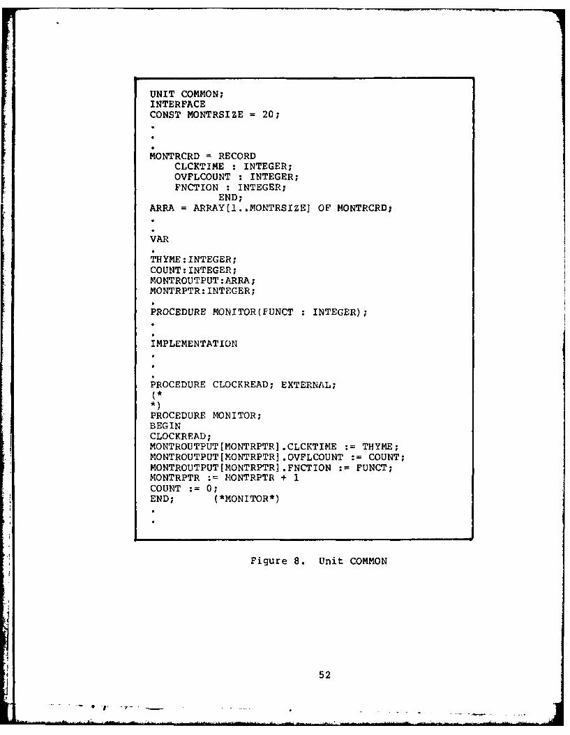
UNIT COMMON;INTERFACECONST MONTRSIZE =20;
MONTRCRD = RECORDCLCKTIME :INTEGER;OVFLCOUNT :INTEGER;PNCTION : INTEGER;
END;ARRA = ARRAY(1..MONTRSIZEI OF MONTRCRD;
VAR
THYME: INTEGER;COUNT: INTEGER;MONTROUTPUT:ARRA;MONTRPTR: INTEGER;
PROCEDURE MONITOR(FUNCT : INTEGER);
IMPLEMENTATION
PROCEDURE CLOCKREAD; EXTERNAL;
PROCEDURE MONITOR;BEGINCLOCKREAD;MONTROUTPUT[MONTRPTR] .CLCKTIME :=THYME;MONTROUTPUT[MONTRPTR] .OVFLCOUNT := COUNT;MONTROUTPUT [MONTRPTRI .FNCTION :=FUNCT;MONTRPTR := MONTRPTR + 1COUNT 0;END; (*MONITOR*)
Figure 8. Unit COMMON
52

(e.g., MONITOR(3f). Because MONITOR is identified in the
INTERFACE section of COMMON, a call to this PASCAL
procedure may be made from any segment of the Roth code
which uses UNIT COMMON. In addition to being identified in
the INTERFACE section, the PASCAL pocedure MONITOR is coded
in the IMPLEMENTATION section of COMMON. Also appearing in
the IMPLEMENTATION section is a PASCAL statement declaring
CLOCKREAD as an external assembly language procedure.
The logic flow of procedure MONITOR is
straightforward. The procedure first calls CLOCKREAD, the
external subroutine, which transfers the clock time from
the BPR to THYME and moves the number of clock overflows to
COUNT. Additionally, the integer parameter passed when
MONITOR was called resides in FUNCT. These three values are
placed in the record element of an array called ARRA, and
the array pointer is incremented by one to point to the
next record for subsequent processing. Control is then
returned to the calling program. The final result of a
series of monitor calls is an array of records, each
containing a clock value, a number of overflows, and an
identifier indicating from where the monitor was called.
The array is then written to diskette by the COMMON
resident PASCAL procedure PRINTMON to permit offline data
analysis.
In addition to modifying COMMON to allow proper host-
subroutine interface, the rcchanics used to rebuild the
Roth system are also unique. Appendix C outlines the
53
procedures required to build the system to permit execution
of the monitor.
PROCESSING THE MONITOR RESULTS
Once all monitoring has been completed, and the array
of clock values has been constructed, the array must be
written to diskette to be used by an offline data reduction
program which will analyze the results of the monitoring
effort. This task is accomplished by the procedure
PRINTMON, which, like MONITOR, resides in the
implementation area of COMMON. PRINTMON is listed in Figure
9, requires no parameter passing, and may be invoked from
any segment which uses UNIT COMMON.
It is worthy to note that either one of two
techniques could have been employed to write the monitor
results to diskette. Either a PASCAL array could have been
created during processing, with the entire array written
to diskette, or the result of each monitor invocation
could have been written on an individual basis as the
results became avzailable. The major disadvantage of
writing the entire array is that the array requires
notable memory resources in an already restricted
environment; conversely, the disadvantage of writing the
individual results is that this action would add
significant overhead to execution times. The first option
was chosen to be implemented, largely because the size of
the monitor data array is "adjustable"; by modifying the
54

UNIT COMMON;INTERFACE
PROCEDURE PRINTMON;
IMPLEMENTATION
PROCEDURE PRINTMON;VAR CNT : INTEGER;
M : INTERACTIVE;BEGIN
REWRITE(M, #5:MONFIL.TEXT');WRITELN(M,' MONITOR RESULTSWRITELN(M);WRITELN(M,' FUNCTION TIME COUNT');WRITELN(M);FOR CNT := 1 TO (MONTRPTR - 1) DOWRITELN(M,' ',MONTROUTPUT[CNT] .FNCTION,'
MONTROUTPUT[CNTI .CLCKTIME,'MONTROUTPUTICNTI.OVFLCOUNT);
CLOSE(M,LOCK)END; (* PRINTMON *)
Figure 9. Procedure PRINTMON
value assigned to the constant MONTRSIZE in the
COMMON UNIT, the corresponding array becomes just large
enough to accommodate the number of monitor calls made. The
PRINTMON procedure makes use of three UCSD PASCAL features
55

iI i
which enhance the capability of writing the file to
diskette. First, the variable M is declared an interactive
type variable. Next, the REWRITE statement is used to open
and create a new file on Logical Unit 5, to be listed in the
disk directory as MONFIL.TEXT. The normal PASCAL WRITELN
statements are then used to write the required information,
with the variable M used to indicate that the data is to be
written to diskette. Finally, the file is closed using the
LOCK option, which permanently places the file name in the
disk directory. Upon completion of the database processing,
the file MONFIL.TEXT may be used to analyze the monitoring
effort. Figure 10 displays a call to PRINTMON after TREE and
subsequent procedures have been monitored and Figure 11
shows the listing of the resulting file MONFIL.TEXT.
MONITOR OVERHEAD
An issue which must be dealt with is the problem of
monitor overhead, i.e., the time required to execute the
monitor. Since an attempt is being made to time the
execution of a set of logic, it does indeed seem vital that
the amount of processor time "wasted" during the actual
measurement be accounted for. Monitor overhead may be
measured in one of two ways: either analytically or
empirically. An analytic measurement would require
determining the execution times of each instruction and
summing them together to reveal the total overhead
56
^I L ' .. . r . . ,, .... .. . . & "I °: i . . ' ,L . ... ... ... ":. .. . . . . .

BEGIN (* EXECUTE *
MONITOR(1) ;TREE (RELLIST,COMFILE,ERROR,CHAIN);MONITOR(2);
BEGININSU PS; PRINTTREE;MONITOR93);PRINTMON;
Figure 10. Calling PRINTMON
MONITOR RESULTS
FUNCTION TIME COUNT
1 0 02 1537 03 1408 0
Figure 11. Monitor Results
57

processing time. An empirical measurement could be
performed by executing a series of monitor calls which
actually monitor themselves, thereby revealing a good
indication of the processing time of each call. A third
alternative would be to combine analytic and empirical
measurement, in turn determining the execution times of
each portion of the monitor logic.
The execution of the monitor is graphically displayed
in Figure 12. The PASCAL host places a call to the
assembly procedure, passing control to the monitor. After
performing some initialization, the procedure loads the
CSR which causes the firing of the Schmitt Trigger and
initiation of the clock. Control then returns to the host
until the Schmitt Trigger interrupt returns control to the
interrupt address. The interrupt routine executes,
returning control to the host until either a clock/counter
overflow occurs, causirng the overflow routine to process,
or until another monitor call is made.
Executing ten successive monitor calls reveals that
the average time required to execute a single call without
overflow is 4200 microseconds (4.2 milliseconds) , as
depicted in Figure 12. Furthermore, analytic measurement
V using Appendix C of the Digital Microcomputers and Memories
Manual (Ref. 9), shows that the actual time required to
execute the monitor instructions without overflow
58

SET CSRFIRE ST2LOAD BPRREINITIATE CLOCK
MONITOR .ST2SRV OFLSRVCALL
* .RTI .RTI
* . RTS* * PC
ASSEMBLY .
PROCEDURE
INTERFACE
PASCALHOST
x. .12.60... .x x26.95xx225.
x ........... 4200.00............... x
*note: all measurements in microseconds
Figure 12. Monitor overhea~d
59

(initialization plus ST2 service routine) is 39.55
microseconds. The processing time required by the overflow
service routine is 22.75 microseconds. As one would expect,
these figures indicate that the large majority of monitor
overhead time (4160.45 microseconds) is consumed by the
UCSD PASCAL monitor interface resident in the COMMON
module. Mathematically, the monitor overhead time may be
represented as follows:
ASSEMBLY SUBROUTINE INITIALIZATION TIME +
ASSEMBLY SUBROUTINE ST2 INTERRUPT SERVICE ROUTINE TIME +
COMMON RESIDENT INTERFACE LOGIC EXECUTION TIME +
(# OVERFLOWS * ASSEMBLY SUBROUTINE OVPL SERVICE ROUTINE TIME)
TOTAL MONITOR OVERHEAD TIME (1)
or,
4200 microseconds +
(# OVERFLOWS * 22.75 microseconds)
TOTAL MONITOR OVERHEAD TIME (2)
DATA REDUCTION AND VERIFICATION
The two remaining objectives required to complete the
development of the Roth Database monitor are the creation
of an offline data reduction program and a test of an
instrumented system which will verify that the monitor will
60

rcollect data and handle overflow conditions properly.
Appendix D is a listing of program ANALYZE, a PASCAL
routine which takes the data recorded in file MONFIL.TEXT
and reduces it to yield overall system execution times.
ANALYZE basically consists of two parts, the reading of
MONFIL.TEXT and the creation of a second disk file,
ANALFIL.TEXT which contains the reduced information. After
it resets the input file, ANALYZE spaces past the first
four header lines and reads the tabular data (Ref. Figure
11) into an array called ANALARRA. An 1*1 is written to the
console screen for every line read from MONFIL.TEXT.
After the array ANALARRA has been created, the data
it contains is transformed into the final monitoring
results and written to diskette file ANALFIL.TEXT, with an
"*" printed to the screen corresponding to every line
written to disk. The first step of this process is to
determine the number of times the actual KWVlI-A
clock/counter overflowed (OVFLTOT), in addition to the
value recorded in the array (ANALARRA[INCR].OVFLCOUNT). The
total overhead is then calculated using Equation 1, where
OVHEAD is equated to the sum of the initialization time,
ST2 service time, and PASCAL overhead time. The total
processing time is then calculated using the following
formula:
(OVERFLOW COUNT * 32767) +
CLOCKTIME -
61

TOTAL OVERHEAD =
TOTAL PROCESSING TIME (3)
Two techniques were employed during this calculation
to permit accurate results. First, variable FINALVAL was
declared as a UCSD "long" integer, capable of storing a
signed decimal value twenty digits in length (Ref. 19, p.
155). Had this procedure not been used, a maximum value of
only 32767 could have been stored in FINALVAL. Second, the
value of TOTOVHED had to be rounded off to ensure
compatability within the mathematical expression.
Before any meaningful results can be drawn from
monitoring the Roth Database optimization logic, a test of
the monitor needs to be performed to verify the following
capabilities:
1. Absence of obvious run-time errors.2. Proper advancement of the clock/counter.
3. Resetting of the BPR to zero each time the trigger is
fired.
4. Proper advancement of the overflow counter.
5. Accurate data reduction and presentation.
These capabilities were indeed verified using the
following techniques:
1. Run-t-ime errors were corrected during normal
62

system execution.
2. Analysis of the results written to disk file
IONFIL.TEXT show that the BPR values placed into the file
contained different values for different procedures
monitored. Additionally, these values appeared to be
commensurate with the time these procedures should require
to process relative to one another. These two observations
supported the supposition that the clock/counter was being
properly advanced.
3. Resetting the BPR at the firing of the trigger was
verified by the fact that the CLCKTIME results stored in
MONFIL.TEXT are obviously not cumulative.
4. In order to verify the advancement of the overflow
counter, two dummy PASCAL FOR .. DO loops were inserted
into the Roth DML code and monitored successively. The
first test, which consisted of an outer FOR .. DO loop of
twenty iterations and an inner FOR .. DO loop of 3200
iterations, caused a value of 9 to be placed in the
overflow counter, and a value of 17562 placed in the
CLCI(TIME variable. Reduction of these values yielded a
processing time of 312474 milliseconds. The outer loop then
was modified from twenty iterations to forty iterations. It
would intuitively seem that the total operating time of the
test logic should also approximately double. In fact, the
overflow counter Went from a value of 9 to 19 and CLCKTIME
changed to 3057, yielding a total value of 625649, almost
j exactly double the first calculated result. Additional
63

modifications further confirmed that the overflow counter
was incremented properly, all the way up to a value of 57.
5. By processing the values appearing in MONFIL.TEXT
using a calculator, the offline reduction program ANALYZE
was verified as correct.
64
64I

V MODELING THE ROTH OPTIMIZATION LOGIC
BACKGROUND
Monitoring the performance of the Roth database
optimization logic is a straightforward means of measuring
the effectiveness of these modules. Unfortunately, however,
successful monitoring is based on the premise that the code
being measured is operational; it is not feasible that
monitor hooks be placed in software that does not achieve
its intended objectives. This limitation to monitoring
makes evident one of the advantages to modeling the
performance of a system - design, not code is the actual
object of the model.
A system may be thought of as a collection of
interacting elements affected by outside forces; converscly,
a model is anh abstraction of this system. In order to
effectively create this abstraction, two things must be
established immediately: the purpose for modeling the system
and the elements of the system which must be included in the
model to provide an accurate representation. The modeling
process may be depicted as:
1. Define the purpose of the model.
2. Establish the boundaries of the system to be modeled.
3. Determine the level (or levels) of detail to be
65

represented.
4. Establish system performance measures.
5. Define design alternatives (parametric and structural)
which, if implemented, could lead to improved performance.
6. Assess results, experiment with alternatives, and
implement the most effective model.
A pictorial representation of this process appears in
Figure 13.
The purpose of this chapter is to address, in detail,
the six steps of the modeling process as it applies to the
Roth database optimization design. Since a model may be
thought of as a laboratory version of a system, the
overriding objective motivating this modeling effort is to
measure the effectiveness of the theories included in the
optimization design and, if required, suggest improvements
to the system which could enhance processing efficiency.
A simulation model which represents a system is
classified as one of two types: discrete change or
continuous change. In most simulation models, including a
model of a database system, time serves as the model's
independent variable. The means by which the dependent
variables fluctuate as a function of time, i.e., at discrete
time intervals or continuously over the time spectrum,
determines the classification of the model. It is noteworthy
that these classifications identify models, not systems, and
66
.1I

SYSTEM
PURPOSE LEVEL OF DETAIL BOUNDARIES
P71FORMANCE DESIGNMEASURES ALTERNATIVES
MO DEL
ANALYS IS
IMPLEMENTATION
Figure 13. The Modeling Process
67
that a single system could possibly be represented by
either a discrete model or a continuous model (or a
combination of the two, called a combined model).
SLAM, the Simulation Language for Alternative
Modeling, is a high order modeling language which permits
simulation in any of the three modes: discrete, continuous,
or combined. SLAM employs a network structure which
consists of symbols called nodes and branches. These
symbols, which depict such items of interest as queues,
servers, and decision points, are combined into a single
network which represents the system being modeled. Entities
are then created and allowed to flow through this pictorial
representation, while statistics are simultaneously being
generated which consequently provide insight into the
capabilities of the system. In addition to the standard
capabilities provided with SLAM, the optional use of
FORTRAN user-written subroutines expands the potential for
the model to provide a realistic representation of the
subj e ct.
Before addressing the model of the Roth logic, a
A brief description of the key SLAM capabilitiLes is
appropriate. The CREATE node is used to generate entites
within the system and permits user specification of
interarrival time, maximum number of entities created, and
number of emanating activiti.es. The QUEUE node permits the
delay of entities at a specified location of the network
until the appropriate server becomes available. The service
68

activity represents actual processing in the system and
either emanates from a queue or is chosen from other
qualified servers by a SELECT node. The GOON node provides
a routing capability to another point in the network with
every entering entity passing directly through the node.
The COLLECT node is used to collect statistics related to
either the time an entity arrives at a node or a variable
at the entity arrival time.
PURPOSE OF THE ROTH MODEL
The purpose of a model of the Roth database
optimization logic is to provide an accurate
representation of data flow beginning with the initial
execution of a command file through the completion of the
execution of the RUN module. SLAM generated statistics
provide an excellent indication of the processing time
required by each logic module, ranging from entire segment
to small procedure. Each entity flowing through the system
represents a relational algebra command, a multi- command
query, an operator tree, or a network of trees depending on
the specific application and location within the system,
with attributes assigned to these entities characterizing
their complexity, type, and anomalies. By modifying these
parameters along with the structure of the network,
potential optimization logic bottlenecks and areas
requiring improvement can be identified.
69
SYSTEM BOUNDARIES
In many modeling applications, establishing system
boundaries is a difficult task which is even sometimes
overlooked. one of the keys to a successful, meaningful
model is clearly defining what it is that needs to be
modeled. If only a portion of an operational activity is to
be analyzed, for example, it is usually not necessary to
model the entire organization. It is absolutely crucial
that a clear beginning point and terminal point be
established before the modeling effort can proceed.
The goals set forth in the requirements chapter of
this thesis dictate that the Roth database system model
should pertain to the optimization logic contained within
the data manipulation language (D?4L), thus establishing the
system boundaries to be modeled. Due to the modular design
of the Roth system, the four optimization modules (TREE,
* SPLITUP, OPTIMIZE and RUN) are all controlled by a central
driver, the EXECUTE procedure. It is noteworthy that the
top-down, modular construction of the database permits a
very straightforward interpretation of optimization logic
boundaries.
LEVELS OF MODELING DETAIL
Due to the complexity of the Roth optimization logic,
the best technique used to model the system is also a top-
down, hierarchical approach, beginning with a simplistic
model of the modules as a whole, and ending with detail
70

which depicts individual PASCAL procedures. The major
advantage to this approach is its vivid representation of
the system. Appendix A contains SLAMII network diagrams
which depict the first two levels of representation of the
Roth optimization modules. Each of these diagrams will be
described in detail.
LEVEL I
The first SLAM diagram, a LEVEL I representation,
serves as a simplistic model of the Roth optimization
modules. A simulation of the Roth logic at this overview
level of detail functions as an introduction to the
processing flow of the modules. At this level of
representation, a single entity corresponds to a given
relational algebra command file, because an overall view of
the optimization logic evaluates the effectiveness of
processing entire command files rather than individual
relational algebra commands. Figure 14 depicts the data flow
represented by the LEVEL I model.
Simplistically stated, a command file is presented as
input to the optimization logic. This transaction is
represented by the creation of an entity in the LEVEL I
model. A total of five entities are created, each
corresponding to one of the benchmark queries provided in
_____ _____ ____71
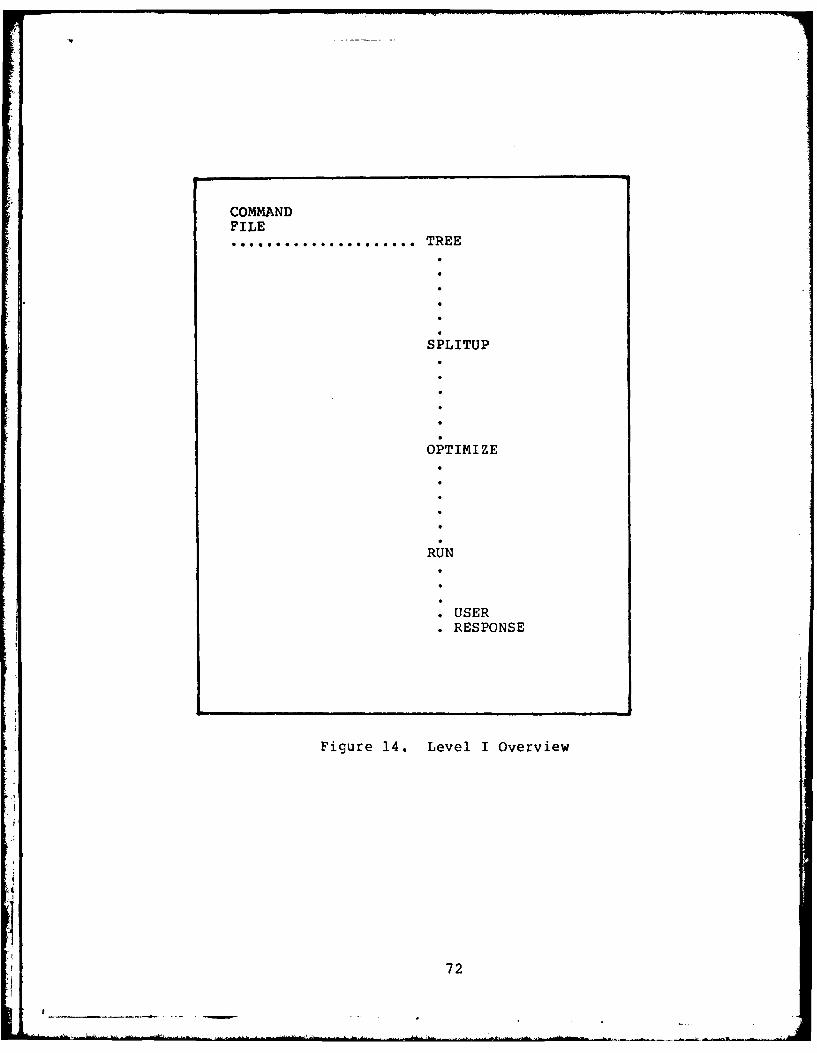
COMMANDFILE
..... TREE
SPLITUP
OPTIMIZE
RUN
* USERRESPONSE
Figure 14. Level I Overview
72

Appendix B. The Roth system completely processes a
given command file before accepting another as input. The
LEVEL I model simulates this by forcing an entity to wait at
the beginning of the simulation flow until the previous
entity is completely through the system. The four
optimization modules are then encountered in order and the
entity terminates as a response to the user. Upon
termination, the succeeding simulated command file is
permitted to begin processing through the optimization
logic.
LEVEL II
The LEVEL II diagrams appearing in Appendix A provide
a more detailed representation of the same logic modeled in
the LEVEL I design. In this instance, each optimization
module is represented by a single SLAM diagram; however, as
an entity exits one module it becomes the input to the
next. This process ties the modules together and provides a
single, stand-alone representation of the Roth optimization
logic at a second level of detail. Unlike the LEVEL I miodel
which simulates the processing of a set of queries, the
LEVEL II model simulates the in-line processing of
individual command files, each consisting of relational
algebra commands.
The first LEVEL II SLAM diagram represents the TREE
optimization procedure. A given command file, which
73

constitutes the input to the TREE module, is simulated by
creating the number of entities corresponding to the number
of commands in the file. These entities then pass through
the TOKEN procedure of the Roth code which returns the type
of command being examined. The remainder of the TREE module
processes these commands individually; thus, after the
execution of the TOKEN procedure, each command is detained
until the preceeding command is allowed to complete TREE
processing. The remaining TREE processing is merely a call
to one of five procedures: DUIP, SELECT, JOIN, PROJECT, or
DIVIDE. In the actual system, these procedures are
responsible for creating the corresponding node of the
operator tree. The specific call depends upon the type of
relational algebra command being executed. At the
completion of this procedure, the subsequent entity is
permitted to proceed. All entities completing the TREE
processing are discarded except the last one, which now
simulates the network of operator trees used as input to
the SPLITUP module.
The next LEVEL II diagram represents the second
optimization module, SPLITUP. At this level of detail,
SPLITUP is straightforward to model, consisting of five
submodules: FINDHEADS, LONGTREE, FIXFIELD, DIVORCE, and
REVCHAIN. SPLITUP receives a single entity, the network of
shared trees provided by TREE. The entity first passes
through activity FINDHEADS, which represents the linking of
the network root nodes. Next, procedure LONGTREE sorts this
74
A-
chain of root nodes, placing the root of the tree with the
greatest number of shared subtrees first, and the root of
the tree with the least number of shared subtrees last. The
next simulated procedure is FIXFIELD, which initializes each
node's attribute field. The entity next encounters the
DIVORCE activity, which separates the shared subtrees from
each tree of the network. Finally, REVCHAIN is encountered.
REVCHAIN reverses the order of the root nodes to permit the
formerly shared subtrees to be executed before the results
of these operator subtrees are utilized. The model of
procedure SPLITUP terminates with the creation of multiple
entities, each representing an individual tree containing no
shared subtrees. These individual trees condstitute the
input to the OPTIMIZE module.
The third SLAM diagram represents the OPTIMIZE module
o ;he Roth optimization logic. As was the case with the
TREE simulation, entities are only permitted to process
individually because the actual OPTIMIZE logic processes a
single tree at a time, As in the system itself, this
portion of the LEVEL II model depicts OPTIMIZE as a sum of
five sub-procedures: COMBOOL, SELDOWN, SIMSEL, PROJDOWN,
and ELIMDUPROJ.
COMBOOL, the first procedure simulated, is
responsible for transforming a unique tree structure called
a "boolean subtree" into a single operator having a single
compound predicate. The algorithm employed by COMBOOL is a
direct implementation of one of the optimization techniques
75
I ~ -- -

under investigation; thus, the experimental modeling of
this procedure at more detailed levels will be significant.
The SELDOWN procedure, executed next by the OPTIMIZE
module, moves SELECT operators down the operator tree. The
tree entity next encounters the SIMSEL activity, which
simplifies the boolean predicates of the SELECT operators.
The next simulated activity encountered is the PROJDOWN
procedure, which moves PROJECT operators down the operator
tree. Finally, the entity traverses the ELIMDUPROJ
procedure, which eliminates duplicate PROJECT operators.
After these five activities have been traversed, the
succeeding entity is permitted to enter the OPTIMIZE logic.
The input to OPTIMIZE was a series of individual trees
created by SPLITUP. The result of OPTIMIZE is a series of
optimized versions of these trees.
The final LEVEL II SLAM diagram depicts the RUN
module of the Roth Database optimization logic. The
baseline design of this procedure was presented in the Roth
Thesis (Ref. 17, p. 77) and partially coded as an
independent study by Lt. Peter Raeth. The module implements
the technique presented in the Smith & Chang paper (Ref.
18), called the Coordinating Operator Constructor. The
model shows that the single entity, representing the
optimized operator tree produced by OPTIMIZE, first flows
through activity INSUPS. INSUPS serves as a prelude to the
actual algorithm which links the opeLator nodes. The entity
then simulates being processed by the activities UPTREE and
76-i- 7 .

DOWNTREE, two submodules which actually perform the RUN
optimization algorithm. Finally, a procedure tentatively
called EXEC is simulated. EXEC will be responsibl.e for
executing the procedure calls created by DOWNTREE. All
entities which complete EXEC processing, except the last
one, are discarded. The last entity exits the system
representing the result of the query being returned to the
user.
Models of the Roth query optimization logic have now
been designed at the first two levels of detail. While it
is beyond the scope of this thesis effort to represent the
system at any further detail level, it is noteworthy that
these two baseline models do provide an excellent overview
of the Roth database optimization modules and an essential
beginning point for future Roth logic modeling.
SYSTEM PERFORMANCE MEASURES
The next step in the modeling process is the
establishment of system performance parameters; i.e., what
values should be used to accurately portray
the roth system processing times, what modifications should
be made to these parameters to correctly reflect different
query operating characteristics, and what SLAM statistics
should be Used to evaluate the outcome of theseK modifications?Because the majority of time devoted to this thesis
was spent developing the software monitor and the design ot
77

a portion of the optimization logic has not yet been
completed, the detailed development of these performance
measurements was not determined to be within the scope of
this effort.
It is noteworthy, however, that determining activity
durations which represent the execution time of sets of
optimization logic is the first step required to
parametrically depict the Roth system. The development of
these values may be performed in one of two ways:
empirically or analytically. Empirical parameter formulation
implies that duration values would be assigned based on
observation. Since the Roth database system is not yet
operational for complex queries, empirical assignment of
parameter values is currently impractical.
Analytic calculation of activity duration times,
then, is the next task required to continue this modeling
effort. Analytically determining these execution times will
be a non-trivial task requiring the analysis of the number
of lines of executed code as well as the number of I/O
transactions performed during the processing of a given
relational algebra query.
DEFINE ALTERNATIVES, EXPERIMENT, AND IMPLEMENT
The final two steps in the modeling process are to
analyze the results ol the simulation effort and attempt to
detect possible weaknesses in the optimization logic which,
if corrected, could further decrease the amount of execution
78
required to perform a given user query. Having uncovered
these potential deficiencies in the system, either
parametric or structural changes to the model can be made,
and the model can be executed again, revealing if these
revisions are beneficial. Based on the observations provided
by the modifications to the model, permanent design and
implementation changes can be made to the Roth system which
will improve the processing efficiency of the data retrieval
function.
SUMMARY
Due to the complex nature of the Roth optimization
modules and the time constraints imposed on the completion
of this project, coding and implementing the model was not
accomplished. Instead, the purpose of the Roth logic model
was defined and the boundaries of the system to be simulated
were established in conjunction with the requirements set
forth in Chapter 3 of this thesis. In addition, the first
two levels of detail were established and represented in the
form of SLAM network diagrams. The next logical step of this
task would be to continue model development to the third,
fourth, and even fifth levels of detail. In concert with
this activity, critical system parameters have to be
-' established. Finally, the diagrams need to be converted to
SLAM code, implemented, analyzed, and modified to provide
experimntal results.
79

VI CONCLUSION
SUMMARY
There were three objectives pursued as the goal of
this thesis. The first objective was to develop an
understanding of state of the art methods used to measure
the performance of database management systems. This
objective was satisfied as a result of the literature
searching accomplished during the initial stage of the
effort.
The second objective of this endeavor was to develop
a practical method of measuring the efficiency of a set of
relational algebra query optimization techniques integrated
within the data manipulation language of the Roth
Pedagogical Relational Database. Research indicated that
not one, but two methods could be used to perform this
measurement. Monitoring the execution of the optimization
logic would clearly display the amount of time required by
individual modules to process a set of benchmark queries
designed to test the system'& capabilities. As an
alternative to monitoring, modeling the Roth optimization
system would provide the capability of evaluating
peformance even before system implementation.
A performance monitor was developed using a
combination of tJCSD PASCAL and assembly level programming
designed to measure the execution time of the Roth
.so

database query optimization modules. Although the monitor
was initially designed strictly for this purpose, it is
noteworthy that use of this software tool is equally
applicable to any UCSD PASCAL program implemented on the
LSI-11/2 Microcomputer. The monitor may be initiated at any
point in PASCAL logic by merely calling PASCAL procedure
MONITOR.
A model of the Roth optimization logic was also
initiated as part of this thesis effort. It was determined
that effective modeling of the Roth system should be
approached in a hierarchical manner, beginning with a
LEVEL I overview of the modules to be simulated.
Subsequent models of the system could then be developed,
each with increased detail which would eventually lead to
an experimental indication of the merit of the optimization
techniques.
The third objective of the project was the
implementation of the optimization logic monitor followed
by as much implementation of the model as permitted during
the time allotted to complete this effort. This objective
was only partially satisfied.
As expected, the greatest liability encountered when
attempting to implement a relational database on a
microprocesser is resource limitation. At the time the
monitor development was nearing completion, and execution
of the Roth manipulation logic using the benchmark queries
in Appendix B was beginning, memory limitation problems
81

became apparent. As a result, only minimal relational
algebra queries, consisting of two commands, could be used
to test the system. While these small queries were
sufficient to validate the monitor, they were unfortunately
not large enough to provide conclusions pertaining to the
effectiveness of the optimization logic. The model of the
system, designed through the second level of detail,
provides an excellent overview of the optimization logic as
well as a beginning point for further development, but
will not provide results until the coding and
implementation stages of more detailed models have been
completed. Two noteworthy areas of difficulty were
uncovered during this thesis effort. They are:
1. Available documentation describing the Version II
UCSD PASCAL System is weak. This difficulty was especially
evidenced during the early implementation of the monitor.
According to the Version II manual, implementing the
external assembly language procedure should be a
straightforward task, simply consisting of declaring the
* external procedure and calling it as any other PASCAL
procedure would be called. What is not documented, however,
is that when attempting to use this technique within
segmented code, a unique problem arises.
Due to the segmentation of the Roth data manipulation
language, applications procedures from which monitor calls
are made reside within one of these PASCAL segments. In
82

order to consolidate all global variables and common
utility procedures, Roth dedicated a PASCAL unit as a
depository for these common elements. It initially seemed
appropriate to declare the external assembly program in
the COMMON unit, and simply call it from one of the
segments of code. The manual implied that this procedure
was legal and would provide predictable results.
The implementation of this technique, however,
resulted in an execution error. Much time and effort was
devoted to attempting to correct this error, including
correspondence with the SOFTECH Corporation, the APPLE
Computer company (which has a similar segmented UCSD PASCAL
system), and the University of California at San Diego
microprocessor laboratory, all to no avail. Finally, at
the suggestion of my thesis advisor, Dr. Hartrum, another
technique was attempted. Rather than call the procedure
from a segment of code, the PASCAL procedure which
actually calls the monitor was inserted into the COMMON
unit. This procedure is then called from the segment of
PASCAL code, effectively ceating a "stepping stone"
affect. The implementation of this technique executed
properly, indicating that an external assembly procedure
can only be called from the segment (or unit) i;which
declares it.
2. A secord technical area of difficulty arose during
the actual testing of the monitor. The Microcomputer
83

Interfaces Handbook published by the Digital Corporation
(Ref. 10), provided the documentation describing the KWV1l-
A clock. While this documentation was generally acceptable,
it did not specifically indicate how the Schmitt Trigger
was fired; i.e., how to initiate the loading of the BPR
with the contents of the counter. With the assistance of
Mr. Dan Zambon, AFIT DEL Engineer, and a call to the local
DEC repesentative, it was learned that setting bit 9 of the
CSR simulates the firing of the Schmitt Trigger.
Operationally, then, every time the monitor is called, the
CSR is loaded with a value which sets bit 9, in turn firing
the trigger and loading the BPR with the clock value.
RECOMMENDATIONS
The recommendations for follow-on effort to this
thesis are as follows:
1. Discover a means of overcoming the LSI-11/2 memory
limitation problem which disallows the execution of complex
queries; once this dilemma has been corrected, monitor the
execution of the optimization logic in accordance with the
requirements set forth on this thesis to determine the
affect these modules have on overall system performance.
2. cdomplete the design, coding, and implementation of
the RUN module to incorporate the Coordinating Operator
Constructor techniques presented in the Smith &Chang paper
(Ref. 18); monitor these techniques as part of the overall
84

optimization logic.
3. Investigate the possibility of extending the model
of the optimization modules to a model of the entire Roth
system, at least at an an overview level of detail to
provide a more concrete view of the interaction of the
data manipulation language.
4. Further develop the baseline model presented in
this thesis by carrying it to the fifth or sixth level of
detail; introduce parametric and structural changes to the
model based on experimental results, in turn leading to
more productive enhancements of the optimization techniques
employed.
FINAL COMMENT
Relational databases provide the wave of the future
in the sea of management information systeits. Additionally,
as hardware miniaturization becomes more prevelent in the
area of data processing, increasing emphasis is being
placed on the improved capabilities of microprocessors.
Accordingly, more and more work is going to be performed in
an attempt to implement relational databases on
microprocessing systems. Two areas of difficulty are going
to surface repeatedly during this implementation:
optimization of retrieval time and efficient use of storage
resources. Hopefully, through efforts such as this one,
microprocessor resident relational databases will become
practical and serve the needs of a variety of users.
85
, 1 '. .'
-. . . ., -.. .... .- ... '>

BIBLIOGRAPHY
1. Date, C.J., An Introduction to Database Systems(Second Edition). Reading: Addison-Wesley, 1977.
2. Ferrari, Domenico, Computer Systems PerformanceEvaluation. Englewood Cliffs: Prentiss-Hall, Inc., 1978.
3. Fonden, Robert W. Design and Implementation of aBackend Multiple- Processor Relational Database ComputerSystem, AFIT Thesis, 1981.
4. Haerder, Theo "A Generalized Access PathStructure," ACM Transactions on Database Systems,3 (3):285-298 (September 1978).
5. Hall, P A V "Optimisation of a Single RelationalExpression in a Relational Data Base System," IBM Journalof Research and Development, 20 (3) : 244-257 (1976)
6. Hawthorn, Paula, & Stonebraker, Michael,"Performance Analysis of a Relational Database ManagementSystem," ACM, 1979.
7. Kambayashi, Yahiko, Database, A Bibliography. USA:Computer Science Press, 1982.
8. Mau, James D. Implementation of a PedagogicalRelational Database System on the LSI-11 Microcomputer,AFIT Thesis, 1981.
9. Microcomputers and Memories. Digital EquipmentCorporation Handbook. Digital Products Marketing, 1981.
10. Microcomputer Interfaces Handbook. DigitalEquipment Corporation Handbook. Digital Products Marketing,1981.
11. Morris, Michael F. & Roth, Paul F., ComputerPerformance Evaluation for Effective Analysis. New York:Van Nostrand Reinhold Co., 1982.
12. Oliver, N.N., & Joyce, John, "Performance Monitorfor a Relational Information System," Proceedings of theAnnual Conference of the ACM, Houston (October, 1976).
13. Pritsker, A. A. B. & Pegden, C. D., Introductionto Simulation and SLAM. West Lafayette: Systems PublishingCorporation, 1979.
86

14. Rodgers, Linda, The Continued Design and Implementation ofa Relational Database System, Masters Thesis, Air ForceInstitute of Technology, Dayton, Ohio, 1982.
15. Rosenberg, Arnold L., and Snyder, Lawrence,"Time- and Space- Optimality in B-Trees," ACM Transactionson Database Systems, 6 (1): 174-193 (March 1981).
16. Ross, Douglas T., "Structured Analysis(SA): ALanguage for Communicating Ideas," IEEE Transactions onSoftware Engineering, SE-3 (1): 16-34 (January 1977).
17. Roth, Mark A., The Design and Implementation of aPedagogical Relational Database System, Masters Thesis, AirForce Institute of Technology, Dayton, Ohio, 1979.
18. Smith, John Miles, and Chang, Philip Yen-Tang,"Optimizing the Performance of a Relational AlgebraDatabase Interface," Communications of the ACM, 18 (10):568-579 (October 1975).
19. UCSD (Mini-Micro Computer) PASCAL, Version II.0,Institute for Information Systems, University ofCalifornia, San Diego (March 1979). (Available throughAFIT/ENE).
20. Yao, S. Binq, "Optimization of Query EvaluationAlgorithms," ACM Transactions on Database Systems, 4 (2):133-155 (June, 1979).
87
*ei

-24 99 [HE PERORMANC ME HREMEN OF A RELA ONA D ATAAE 2/2SSEM USNGMONTOH .UJ AIR FORCE I FTC
WRIGHT-A HERON AB OTSHOOL 0F ENGI L SNYDR
EEEEEEEhEE
11-
II1.25 11.4 1.
4 MICROCOPY RESOLUTION TEST CHARTMA71ON4AL OURfEAU Of S1ANOARI)-193-A

APPENDIX A
ROTH OPTIMIZATION LOGIC MODEL -
SLAM NETWORK DIAGRAMS
This appendix is a collection of SLAM network
diagrams which depict the Roth database system at the
first and second levels of detail.
The first SLAM diagram serves as an overview of the
Roth optimization logic and is designed at detail LEVEL I.
At this level, an entity in the system represents an entire
relational algebra query. For this baseline model, five
queries are created by the CREATE node, each corresponding
to one of the benchmark queries appearing in Appendix B.
The creation of the queries begins at system time zero, and
the entities are created at an inter-creation time of 1
time unit. One time unit was nominally chosen as a
value for this parameter because the inter-arrival rate is
insignificant; after all entities are created, only one is
allowed to proceed through the logic at a time. After
creation, an entity first encounters an AWAIT node which
monitors the status of the SLAM RESOURCE Optimize. The
purpose of this technique is to preclude an entity from
processing through the optimization logic until the
preceeding entity has completed executing. This is done to
simulate the fact that the Roth logic processes a single
88
f ___ - ...............-

command file at a time. If the RESOURCE is free, the entity
seizes its services and proceeds. The simulated command
file encounters four successive activities, corresponding
to the four Roth optimization modules: TREE, SPLITUP,
OPTIMIZE, and RUN. After completing the RUN activity, the
entity frees the Optimize RESOURCE, in turn permitting
processing of the subsequent command file. Finally, the
entity terminates, simulating a response to the user.
89
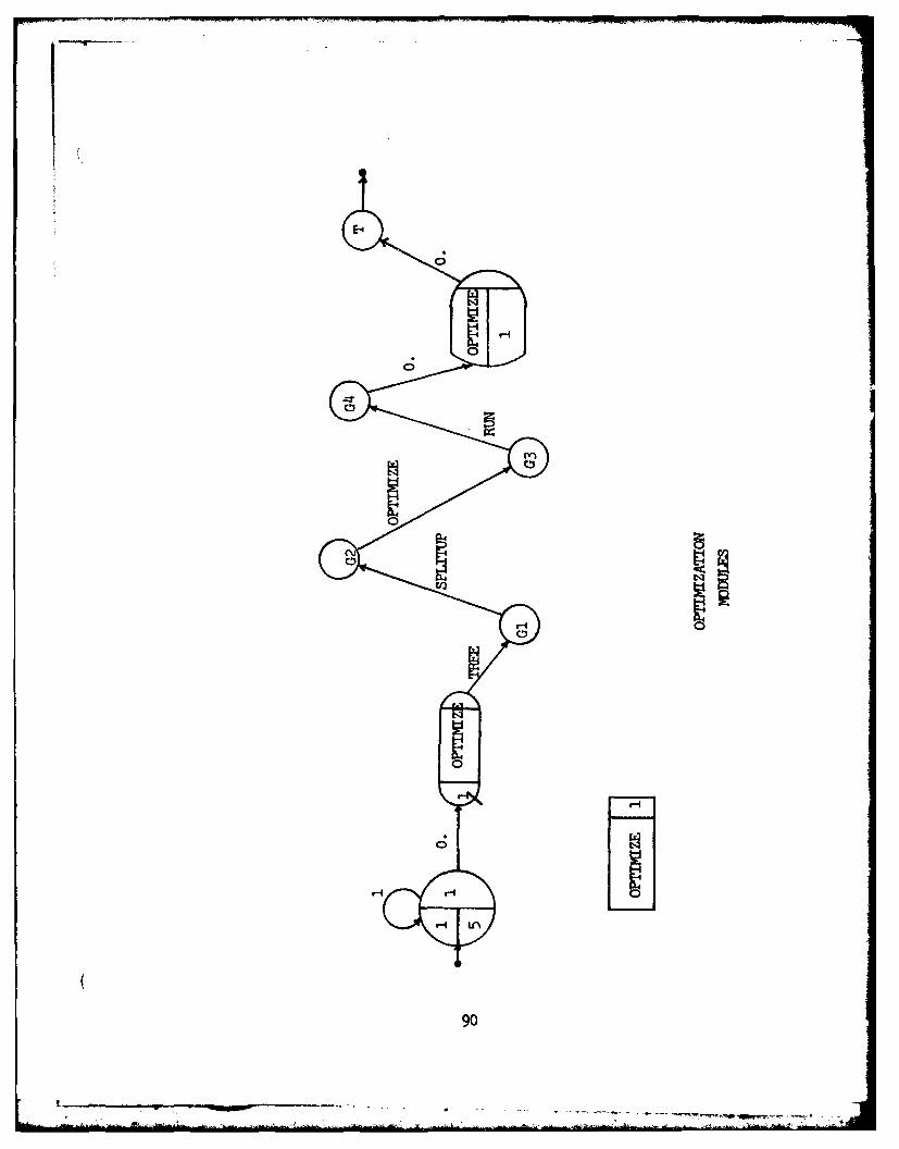
E-HE
90
The LEVEL II representation in Appendix A presents
the model of the Roth optimization logic at the next level
of detail. LEVEL II actually consists of four individual
diagrams, each corresponding to one of the optimization
modules. Each diagram is related to the other three in that
as is the case with the logic represented, the result of
one optimization module becomes the input to the next.
The first LEVEL II diagram represents the TREE
optimization module. At the CREATE node, a set of n
entities, each representing a relational algebra command,
is created. Because TREE is the first of the four
optimization modules, creating this command file simulates
the input of a command file to the TREE procedure in the
actual system. The number of commands created depends upon
the size of the query being experimented with. Each entity
generated is then assigned an integer value which
corresponds to one of the eight possible relational algebra
command types used by the Roth database system. The integer
designations are:
1 - UNION
2 - DIFFERENCE
3 - INTERSECT
4 - PRODUCT
5 - SELECT
91
.. 7 w!. I ~ - - - - - . - -

6 - JOIN
7 - PROJECT
8 - DIVIDE
After the entity is assigned its type representation,
it passes through a SLAM service activity which simulates
the TOKEN procedure. In the actual system, TOKEN returns
the type name of the command being processed. At this
point, the entities are queued, allowing them to be
individually processed by the remainder of the TREE
procedure. The actual TREE processing is a call to one of
five sub-procedures: DUIP, SELECT, JOIN, PROJECT, or
DIVIDE. The specific call being made depends upon the type
of command being processed; i.e., the function name
returned by TOKEN. This processing capability is treated as
a resource in the model, with each entity in the queue
individually seizing control of processing and subsequently
freeing the resource when it has completed, in turn
permitting the next entity to process. The type of
processing chosen is based on the integer command type
representation acquired at the assign node. After
processing is completed, the entity increments a counter
kept in variable XX(ll) and either exits the model at
terminal node T or continues through GOON node GOSPLIT,
depending on whether it was the last entity createdi i.e.,
the last command in the query. When the last entity passes
through the GOON node, it represents a single network of
92
L 1iI7 '~'~ - -

operator trees created by procedure TREE which also serves
as input to the SPLITUP module.
I
I

1-4 -4 - C4
I-I
04:
.1o
*.1.
914
I
The second LEVEL II diagram represents the second
optimization module, SPLITUP. The model of SPLITUP
basically consists of five service activities, each
corresponding to one of the actual module's five
subprocedures. SPLITUP receives a single entity as input,
representing the network of shared operator trees provided
by TREE. The entity must first be assigned parameter values
repesenting characteristics of the network. Attribute 1
(A(1)) is assigned the current clocktime. A(2), represented
by m in the diagram, obtains the number of nodes in the
network. Finally, A(3) s set equal to the number of root
nodes in the network of shared trees.
The entity next passes through the activity
FINDHEADS, which in the actual system links the root nodes
of the network. The next activity encountered is LONGTREE.
In Roth's logic, LONGTREE sorts the input chain of root
nodes, placing the root of the tree with the greatest
number of shared subtrees first, and the root of the tree
with the least number of shared subtrees last. The next
simulated procedure is FIXFIELD, which initializes each
node's attribute field. The entity then encounters the
DIVORCE activity, which separates the shared subtrees from
each tree of the network. Finally, REVCHAIN is encountered.
REVCHAIN reverses the order of the root nodes to permit the
formerly shared subtrees to be executed before the results
of these operator trees are utilized. Following REVCHAIN
95

processing, the entity passes through a GOON node labeled
G, which splits the entity into a finite number of
entities, each representing an individual tree containing
no shared subtrees. These individual trees are then queued,
passing on to GOON node GOOPT, and in turn providing input
to the OPTIMIZE module.
96

U- ~

The third LEVEL II diagram represents the next
optimization module, OPTIMIZE. Like the TREE procedure,
OPTIMIZE can only process a single entity at a time. Like
SPLITUP, OPTIMIZE may be represented as a collection of
service activities, each corresponding to a sub-procedure
of OPTIMIZE itself.
As each entity enters OPTIMIZE, it must first obtain
RESOURCE PROCESS before it may proceed with execution. The
first activity encountered is COMBOOL. In the actual
system, COMBOOL is responsible for converting unique data
structures called "boolean subtrees" into single
operators. After COMBOOL processing, the entity enters
procedure SELDOWN, responsible for further optimizing
the parse tree by moving SELECT operators down the operator
tree. The SIMSEL activity then represents the logic which
is responsible for simplifying complex SELECT operator
boolean predicates. PROJDOWN then pushes PROJECT operators
down the tree. Finally, duplicate PROJECT operators are
eliminated by the ELIMDUPROJ algorithm.
After ELIMDUPROJ has been traversed, the entity frees
the PROCESS RESOURCE, permitting the subsequent tree to
begin execution. The entity then goes through GOON node
GORUN as input to module RUN.
98
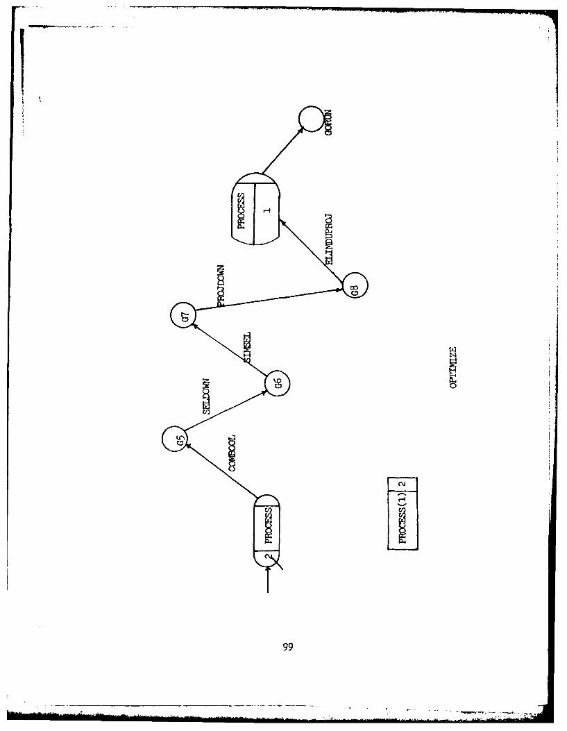
0
PL(V
99

IThe final LEVEL II SLAM diagram depicts the RUN
module of the Roth database optimization logic. The model
shows that the single entity, representing the optimized
operator tree produced by OPTIMIZE, first flows through
activity INSUPS. The procedure INSUPS serves as a prelude
to the actual algorithm which links the operator nodes. The
entity then simulates processing by the activities UPTREE
and DOWNTREE, two submodules which actually perform the RUN
optimization algorithm. Finally, a procedure tentatively
called EXEC is simulated. EXEC is responsible for executing
the procedure calls created by DOWNTREE. Each time an
entity completes EXEC processing, SLAM variable XX(12) is
incremented. When the value of XX(12) reaches q, the number
of trees output by OPTIMIZE, a single entity exits the
system at terminal node TERM, representing the result of
the command file being returned to the user.
100

V-4
4
C,~
10
Ma\
APPENDIX B
BENCHMARK QUERIES
OVERVIEW
In order to measure the effectiveness of the
optimization techniques employed by the Roth database
logic, a set of benchmark queries, along with a set of
test relations must be created. These queries and
relations should be designed specifically to verify the
Roth optimization techniques; i.e., to determine whether
the optimization modules are successfully satisfying their
objectives.
The scenario forming a basis for the benchmark
queries was chosen from a paper by P. A. V. Hall which
documents relational database research performed at the IBM
UK Scientific Centre at Peterlee, England (Ref. 5). TheAI
scenario deals with automating the functions of a library
using a relational database. The appropriate information
required to support this library is stored in eleven
specific relations, each of which is pictured in Table I.
QUERIES
4 The first benchmark command file is designed to
exercise the SPLITUP logic, and actually consists of three
queries which utilize shared subtrees.
102

(Qi) JOIN ACQ, LON WHERE ACQNO = ACQNO GIVING Ti
JOIN T1, BRW WHERE BRWNO =BRWNO GIVING T2
SELECT ALL FROM T2 WHERE PRICE > 10.00 GIVING T3
JOIN T3, STS WHERE STAT = STAT GIVING T4
SELECT ALL FROM T4 WHERE (STAT = A AND PRICE > 10.00)
GIVING T5
PROJECT T5 OVER TITL, PRICE, NUMB GIVING RESULT
JOIN ACQ, LON WHERE ACQNO = ACQNO GIVING TI
JOIN Ti, BRW WHERE BRWNO = BRWNO GIVING T2
PROJECT T2 OVER ACQNO GIVING RESULT
JOIN ACQ, LON WHERE ACQNO = ACQNO GIVING Ti
JOIN TI, BRW WHERE BRWNO = BRWNO GIVING T2
SELECT ALL FROM T2 WHERE PRICE > 10.00 GIVING T3
PROJECT T3 OVER ACQNO GIVING RESULT
Query 2 is designed to test the SELDOWN and PROJDOWN
algorithmr nd consists solely of SELECT and PROJECT
operators.
(Q2) PROJECT ACQ OVER ACQNO, AUTH, TITL, PUBLYEAR, PRICE
GIVING Ti
PROJECT TI OVER ACQNO, AUTH, TITL, PUBL, YEAR GIVING T2
SELECT ALL FROM T2 WHERE (PUBL = MCGRAW HILL) GIVING Si
PROJECT Si OVER ACQNO, AUTH, TITL, PUBL GIVING T3
103
...... ........

PROJECT T3 OVER ACQNO, AUTH, TITL GIVING T4
PROJECT T4 OVER ACQNO, AUTH GIVING T5
SELECT ALL FROM T5 WHERE (ACQNO < 100) GIVING S2
PROJECT S2 OVER ACQNO GIVING RESULT
Query 3 also tests the SELDOWN and PROJDOWN
algorithms, this time by naturally placing the SELECT and
PROJECT operators at the bottom of the operator tree.
(03) SELECT ALL FROM ACQ WHERE (AUTH = HAWTHORNE) GIVING Ti
PROJECT Ti OVER ACQNO GIVING T2
JOIN T2, LON WHERE ACQNO = ACQNO GIVING T3
JOIN T3, BR; 9ERE BRWNO = BRWNO GIVING RESULT
Query 5 tests the COMBOOL algorithm employed by the
RUN module of the Roth logic. COMBOOL works on the
principle that improved efficiency can be obtained by
transforming "boolean subtrees" into single operators which
read storage-resident relations only once instead of
multiple times. Query 5, when directly implemented,
provides an operator tree identical to the one appearing in
the Roth thesis (Ref. 17, Figure 12).
(Q4) SELECT ALL FROM ACQ WHERE ACQNO < 200 GIVING Ti
SELECT ALL FROM ACQ WHERE ACQNO > 500 GIVING T2
104
.--J-0- ----- ~----- ----- -

i UNION TI, T2 GIVING T3
SELECT ALL FROM T3 WHERE AUTH = HAWTHORNE GIVING T4
SELECT ALL FROM ACQ WHERE (ACQNO < 50 AND ACONO > 650)
GIVING T5
INTERSECT T4, T5 GIVING RESULT
Within the EXECUTE procedure, which serves as a
driver during the optimization processing, a copy of the
optimized operator tree is printed to the terminal using
the PRINTTREE procedure. An interesting test of execution
time efficiency would be to measure Query 5 from beginning
of execution through completion of the RUN module, and
then, using the PRINTTREE output, to measure the same
processing interval using the optimized version of the same
query.
(05) UNION LON, LTD GIVING Ti
PROJECT HIST OVER ACQNO, BRWNO, DATOUT GIVING T2
INTERSECT Ti, T2 GIVING T3 DIFFERENCE T3, LON GIVING T4
PRODUCT T4, BRW GIVING T5
SELECT ALL FROM T5 WHERE BRWNO = BRWNO GIVING T6
PROJECT T6 OVER ACQNO, DATOUTBRNAM GIVING T7
JOIN T7, HIST WHERE ACQNO = ACQNO GIVING T8
PROJECT T8 OVER ACQNO, DATOUT, DATIN GIVING RESULT
105

RELATION COMPONENTS
1 2 3 4 5 6 7
ACQ ACQNO AUTH TITL PUBL YEAR PRICE CODE
NACQ ACQNO AUTH TITL PUBL YEAR PRICE CODE
LACQ ACQNO AUTH TITL PUBL YEAR PRICE CODE
PACQ ACQNO AUTH TITL PUBL YEAR PRICE CODE
DDC CODE SUBJ
BRW BRWNO BRWNAM ADD STAT
STS STAT NUMB PERD
LON ACQNO BRWINO DATOIJT
LTD ACQNO BRWNO DATOUT
RTD ACQNO DATIN
HIST ACQNO BRWNO DATOUT DATIN
Table I. Test Relations of the Library Data Base14
I 106

APPENDIX C
CONSTRUCTING THE MONITOR SYSTEM
OVERVIEW
The Roth database system is written using the UCSD
PASCAL language. Because of its length, however, the
entire system could not be placed in a single source file.
As a result, the code had to be segmented using the UCSD
PASCAL segmentation feature. Each segment is individually
compiled with the compiled segments then pieced together
using the LIBRARIAN utility. Finally, the resulting
library is linked together using the system LINKER, with
the external assembly subroutine copied into the COMMON
Unit where it was declared. A description of this process
follows:
COMPILATION
Each segment, along with the COMMON Unit, must be
individually compiled. It is imperative that the compiler
directive (*$S+*) appear as the first line of code in each
segment to place the compiler in swapping mode, in turn
eliminating the danger of exceeding system resources. The
COMMON Unit must be compiled first, so that it may be
placed into the system library to be used during the
subsequent compilation of the remaining segments.
107

LIBRARIAN
As the name implies, the LIBRARIAN is a system
utility which is used to create a library. During the
creation of the monitor system, the LIBRARIAN is used in
two instances.
Once the COMMON unit has been compiled and placed in
its own file (COMMON.CODE), it must be added to the
existing system library so it is accessible during the
compilation of the remaining segments. Appendix A of the
Rodgers thesis (Ref. 19) outlines this procedure. After
the system library is modified to include the newly
compiled COMMON Unit, each remaining segment of Roth
source code must be recompiled and placed in its own .CODE
file.
BUILDING THE SYSTEM
After each segment has been recompiled using the new
system library, LIBRARIAN must once again be used to build
the segmented Roth system. For the purposes of this
example, it is assumed that a segmented system .CODE file,
called LIBRY.CODE, is already available, thus requiring
that the existing segments be replaced with the newly
compiled .CODE files. The sequence is as follows:
The user types an "X" at the system level.
108
! ~- - v

The system responds with:
EXECUTE WHAT CODE FILE --- >
The user enters "LIBRARY".
The system responds:
OUTPUT CODE FILE --
At the point, the user needs to enter the name of the
file which will contain the new library. For our example,
the user enters LIBRY.CODE.
The system then prompts:
LINK CODE FILE --- >
The user is now being requested to provide the name
of the existing library; i. e., the library which needs to
be modified. In our example, the link file is the same as
the output file, so the user enters LIBRY.CODE.
'~1 The system then presents a library map which
identifies what currently exists in each segment of the
link code file. A typical example of the existing Roth
system would appear as follows:
109

0- 0 4- 0 8- 0 12-INVENTOR 1888
1-DB 8140 5- 0 9- 0 13-EXECUTE 12848
2-PASCALIO 1824 6- 0 10-COMMON 936 14-TREE 9132
3-DECOPS 2092 7- 0 11-DEFINE 5382 15-RUN 8936
The user's task is to replace those segments existing
in the current file with the newly compiled segments which
were recompiled using the modified COMMON. Segments 2 and
3 of this example contain PASCAL library system segments
which were not compiled using COMMON. For this reason, the
first step is to merely copy these two segments into the
output code file. The system prompt is:
Segment # to link and <space>, N)ew file, Q)uit, A)bort
The user responds:
2 (space)
The system prompts:
Seg to link into?
The user responds:
2 (space)
110
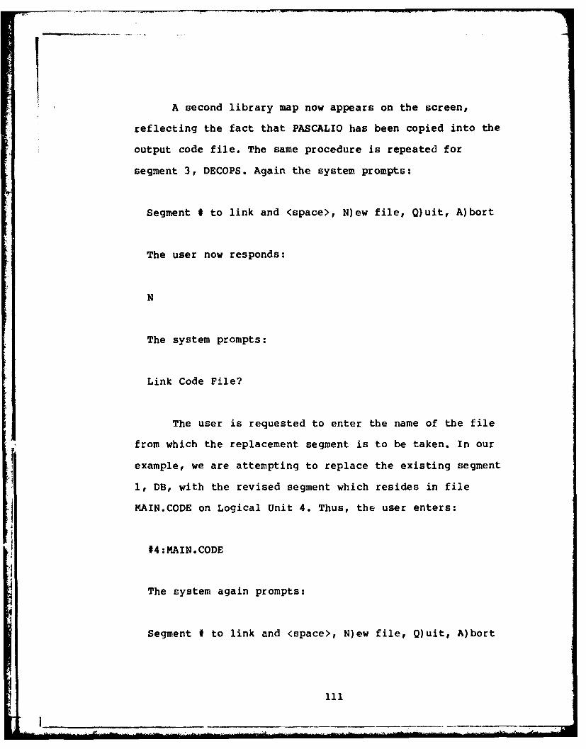
II
A second library map now appears on the screen,
reflecting the fact that PASCALIO has been copied into the
output code file. The same procedure is repeated for
segment 3, DECOPS. Again the system prompts:
Segment # to link and <space>, N)ew file, Q)uit, A)bort
The user now responds:
N
The system prompts:
Link Code File?
The user is requested to enter the name of the file
from which the replacement segment is to be taken. In our
example, we are attempting to replace the existing segment
1, DB, with the revised segment which resides in file
MAIN.CODE on Logical Unit 4. Thus, the user enters:
#4:MAIN.CODE
The system again prompts:
Segment # to link and <space>, N)ew file, Q)uit, A)bort
111
1I~~
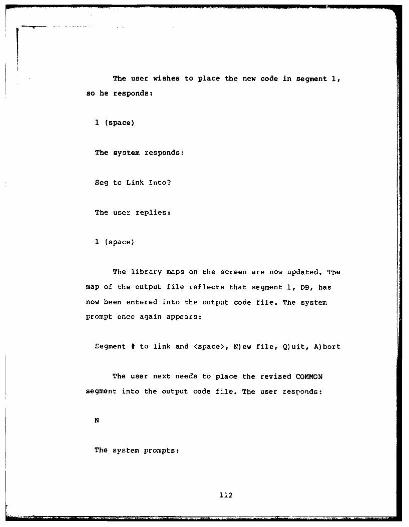
IThe user wishes to place the new code in segment 1,
so he responds:
I (space)
The system responds:
Seg to Link Into?
The user replies:
1 (space)
The library maps on the screen are now updated. The
map of the output file reflects that segment 1, DB, has
now been entered into the output code file. The system
prompt once again appears:
Segment # to link and <space>, N)ew file, Q)uit, A)bort
The user next needs to place the revised COMMON
segment into the output code file. The user responds:
N
The system prompts:
112
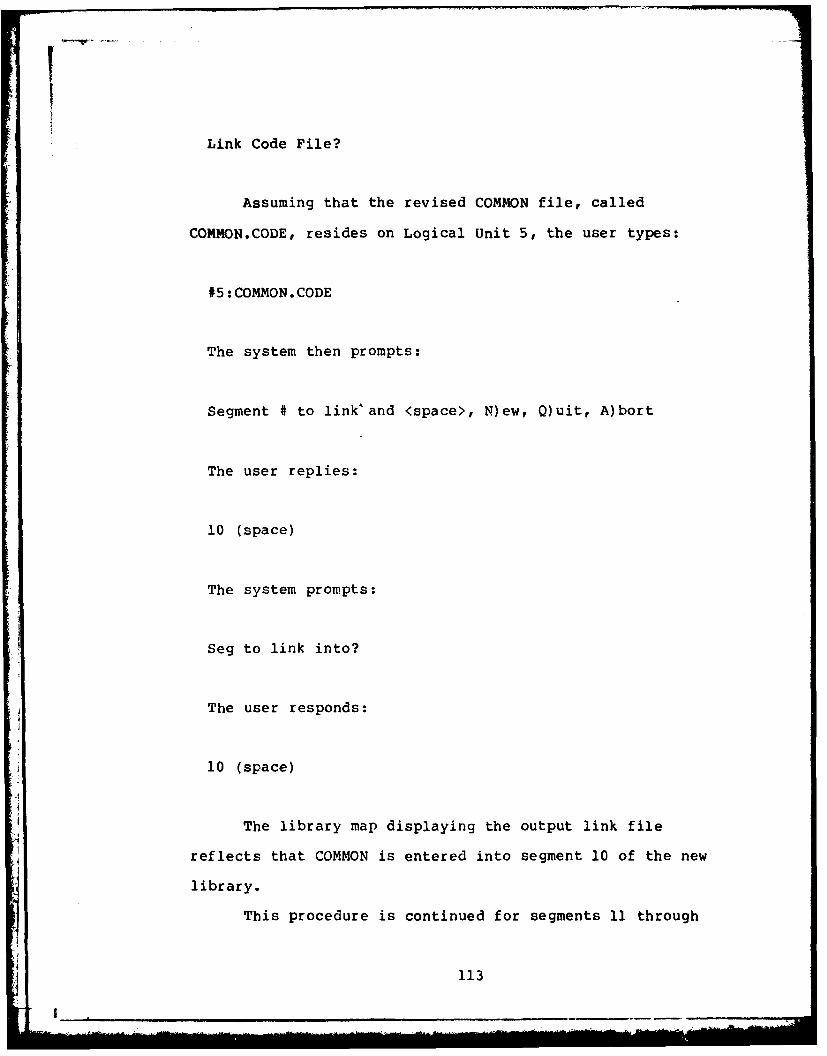
ILink Code File?
Assuming that the revised COMMON file, called
COMMON.CODE, resides on Logical Unit 5, the user types:
#5:COMMON.CODE
The system then prompts:
Segment # to link'and <space>, N)ew, Q)uit, A)bort
The user replies:
10 (space)
The system prompts:
Seg to link into?
The user responds:
10 (space)
The library map displaying the output link file
reflects that COMMON is entered into segment 10 of the new
library.
This procedure is continued for segments 11 through
113

T
15. After replacing segment 15, the system once again
prompts:
Segment # to link and <space>, N)ew, Q)uit, A)bort
The user now enters:
Q
The system replies:
notice?
The user enters a carriage return.
The system has now been reconstructed using the
LIBRARIAN utility, and must now be processed through the
LINKER before being executed. A description of the
LIBRARIAN intrinsics may be found in Section 4.2 of the
UCSD PASCAL Version II.0 Manual (Ref. 19).
LINKER
The linker serves two functions during the creation
of the Roth executable system. First, it links the newly
constructed PASCAL library which consists of the segments
containing the Roth code. Second, it permits the assembly
file CLOCKREAD to be copied into the system so that it may
114
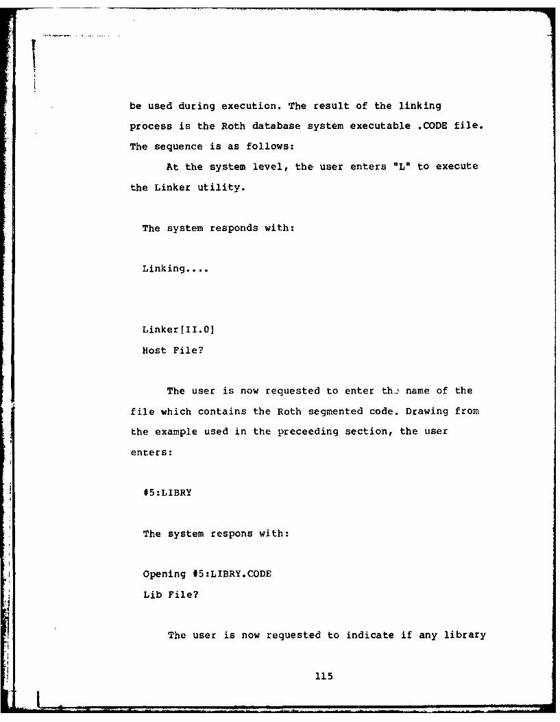
be used during execution. The result of the linking
process is the Roth database system executable .CODE file.
The sequence is as follows:
At the system level, the user enters "L* to execute
the Linker utility.
The system responds with:
Linking....
Linker[II.01
Host File?
The user is now requested to enter th- name of the
file which contains the Roth segmented code. Drawing from
the example used in the preceeding section, the user
enters:
#5:LIBRY
The system respons with:
Opening #5:LIBRY.CODE
Lib File?
The user is now requested to indicate if any library
115
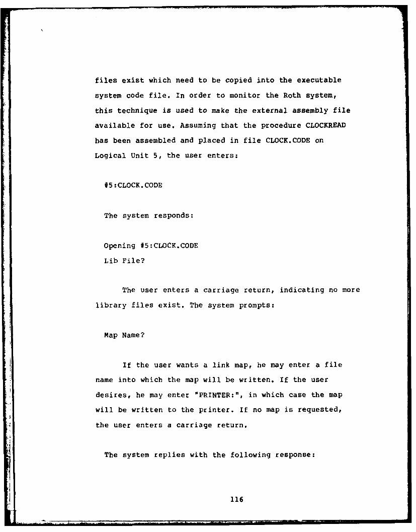
files exist which need to be copied into the executable
system code file. In order to monitor the Roth system,
this technique is used to make the external assembly file
available for use. Assuming that the procedure CLOCKREAD
has been assembled and placed in file CLOCK.CODE on
Logical Unit 5, the user enters:
#5:CLOCK.CODE
The system responds:
Opening #5:CLOCK.CODE
Lib File?
The user enters a carriage return, indicating no more
library files exist. The system prompts:
Map Name?
If the user wants a link map, he may enter a file
name into which the map will be written. If the user
desires, he may enter "PRINTER:", in which case the map
will be written to the printer. If no map is requested,
the user enters a carriage return.
The system replies with the following response:
116
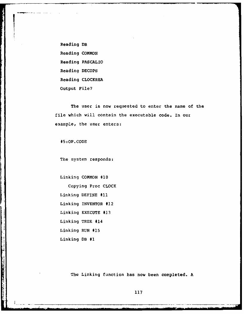
Reading DB
Reading COMMON
Reading PASCALIO
Reading DECOPS
Reading CLOCKREA
Output File?
The user is now requested to enter the name of the
file which will contain the executable code. In our
example, the user enters:
#5:OP.CODE
The system responds:
Linking COMMON #10
Copying Proc CLOCK
Linking DEFINE #11
Linking INVENTOR #12
Linking EXECUTE #13
Linking TREE #14
Linking RUN #15
Linking DB #1
The Linking function has now been completed. A
117

detailed description of the Linker utility appears in
Section 1.8 of the UCSD PASCAL Version II.0 Manual (Ref.
19).
The executable version of the Roth logic, including
the assembled copy of the external procedure CLOCKREAD now
resides in file OP.CODE.
118
! _____________________ - - - - - - - - - - - -

APPENDIX D
PROGRAM ANALYZE
DATE: 8 OCT 82VERSION: 1
NAME: ANALYZEMODULE NUM: N/A
FUNCTION: The function of this offline program is toread the data contained in disk fileMONFIL.TEXT and convert it to total monitoringtime. The finalized output is then written todisk file ANALFIL.TEXT.
INPUTS: NoneOUTPUTS: None
GBL VAR USED: NoneGBL VAR CHNGD: NoneGBL TBL USED: None
GBL TBL CHNGD: NoneFILES READ: Disk file MONFIL.TEXT
FILES WRITTEN: Disk file ANALFIL.TEXTMODULES CALLED: NoneCALLING MODULES: None
AUTHOR: Capt Gary L. SnyderGCS - 82D
- ---------------------------------------------------------------
PROGRAM ANALYZE;CONST
ANALSIZE = 20;OVHEAD = 4.200;OFLOHEAD = 2.275E-2;HALFBUFF = 32767;
TYPEANALRCRD = RECORD
CLCKTIME : INTEGER;OVFLCOUNT : INTEGER;FNCTION : INTEGER;
END;ARRA = ARRAY[I..ANALSIZE] OF ANALRCRD;
VARCNTINCRARRACNT : INTEGER;M,A : INTERACTIVE;
119

ANALARRA :ARRA;FINALVAL :INTEGER[2OI;TOTOVHED :REAL;OVFLTOT :INTEGER;
BEGIN
READ EXISTING DATA OFF FILE MONFIL.TEXTAND CREATE DATA ARRAY ANALARRA
RESET(M,15:MONFIL.TEXT');WRITELN(' PROGRAM ANALYZE');WRITELN( 'READING MONFIL.TEXT FROM DISKETTE');CNT := 0;
FOR INCR := 1 TO 4 DOBEGINREADLN(M);WRITELN('*');END;
WHILE NOT EOF(M) DOBEGINCNT := CNT + 1;READLN (M,ANALARRA ICNT . FNCTION,
ANALARRA [CNT] .CLCKTIME,ANALARRA[CNT] .OVFLCOUNT);
WRITELN('*');END;
DERIVE FINAL MONITOR TIMEAND PLACE IN VARIABLE FINALVAL
REWRITE(A,'#5:ANALFIL.TEXT');WRITELN('WRITING TO FILE ANALFIL.TEXT');WRITELN(A, 'ROTH DATABASE MONITOR RESULTS');WRITELN(A);FOR 114CR := 2 TO CNT-1 DO
BEGINOVFLTOT :ANALARRA[INCR].OVFLCOUNT DIV 2;TOTOVHED :OVHEAD + (OVFLTOT * OFLOHEAD);FINALVAL :HALFBUFF;FINALVAL :-ANALARRA[INCRI .OVFLCOUNT * FINALVAL;FINALVAL :=FINALVAL + ANALARRA[INCR].CLCKTIME;FINALVAL :FINALVAL - ROUND(TOTOVHED);WRITELN (A,' TOTAL EXECUTION TIME OF FUNCTION
ANALARRA[INCR].FNCTIONti IS ',
120
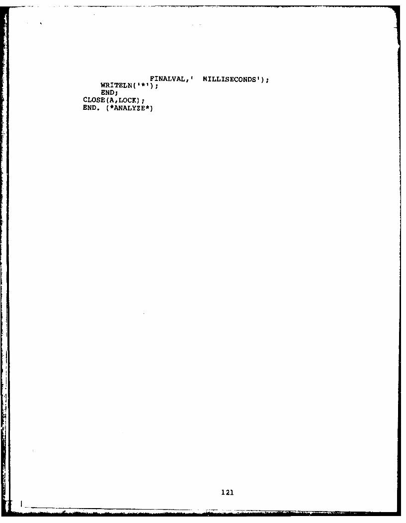
FINALVAL,' MILLISECONDS');WRITELN( 1*1);
END;CLOSE (A,LOCK);END. (*ANALYZE*)
121

APPENDIX E
PAPER
THE PERFORMANCE MEASUREMENT OF A
RELATIONAL DATABASE SYSTEM
USING MONITORING AND MODELING TECHNIQUES
Gary L. Snyder
Capt, USAF
Air Force Institute
of
Technology
ABSTRACT
An investigation was conducted intended to uncover a
productive means of measuring the effectiveness of a
collection of untested relational algebra query
optimization techniques integrated within an existing
microprocessor-resident relational database.
As a result of this research, two methods of
performance measurement were proposed. A software monitor
was designed, coded, and tested specifically to determine
if the employed optimization methods actually decrease the
122

'l
amount of processing time required to execute a given
query. Additionally, a baseline simulation model was
designed and presented as an alternative means of analyzing
the performance of this optimization logic.
INTRODUCTION
In the mid-1970's a new kind of management
information system was devised based on relational
mathematics appropriately called the "relational database".
While this type of database is often heralded as the
information system of the future, it has also been
criticized as being slow and inefficient.
In 1979, an Air Force Lieutenant named Mark Roth set
out to design, code, and implement a pedagogical relational
database on a commercially available microcomputer. Roth
placed emphasis on the data handling efficiency of his data
manipulation language by employing two data performance
techniques. The first technique, inspired by Theo Haerder
(Ref. 4), relates tuples of one relation to tuples of
another yielding ordering and associative access by
attributes to provide efficient updates.
The second technique, inspired by an article by Dr.
John Miles Smith and Philip Yen-Tang Chang (Ref. 18), may
be referred to as an "automatic query optimizer interface"
which logically resides between a user's set of query
commands and the data residing in the system. This
optimization logic modifies any set of commands such that
123
no matter how inefficiently the original query was
constructed, it would be executed using the least amount of
processing time possible.
Research indicates that the Roth system is the first
attempt to operationally incorporate these query
optimization techniques within an actual relational
database. The potential benefits and untested status of
this automatic programmer suggest the purpose of this
paper: investigate techniques to measure the execution time
of complex relational algebra queries in an attempt to
verify the correctness and merit of the optimization
methods utilized.
STATEMENT OF PROBLEM
The purpose of this paper is to address performance
measurement techniques applicable to database management
systems and propose practical methods which will permit the
performance analysis of the Roth relational database
optimization modules. The Roth system is written using the
UCSD PASCAL programming language and resides on the LSI-
11/2 microcomputer.
OVERVIEW OF THE OPTIMIZATION LOGIC
The Roth database was designed to achieve as near
optimal behavior as possible by emphasizing query
optimization at the conceptual level. It was felt that
relational database systems provide users with tabular
124

views of data and consequently highly inefficient queries
are often created. The burden of efficiency should be
transferred from the user to the automatic optimization
interface.
The interface logic attempts to optimize a given
command file in two ways. First, an operator parse tree is
built with each node corresponding to one of the relational
algebra commands in the file. The tree is then rearranged
with the intent of decreasing the time required to perform
the subsequent retrieval. Second, this partially optimized
tree is analyzed in terms of temporary relations to be
created. The tuples of these relations are then preordered
to enhance any searching required to process the data.
The Roth optimization interface appears in the
EXECUTE module of the overall data manipulation language.
The interface itself consists of four PASCAL procedures
designed modularly using a top-down structured approach.
The TREE procedure creates the operator tree and performs
syntax checking. SPLITUP then transforms this single
operator tree into a network of non-shared subtrees.
OPTIM4IZE then exercises algorithms designed to manipulate
the tree to provide a more optimally constructed structure.
Finally, RUN orders the temporary relations created and
performs the actual retrieval. A comparison of these
procedures to the design proposed in the Smith & Chang
paper (Ref. 18) points out the similarity of the two
suggested automatic interfaces.
125

REQUIREMENTS
Because the goal of this research is to address
viable means of database performance analysis, specific
measurement requirements must next be discussed. Three
measurement procedures have been identified to provide the
information necessary to make an assessment of the
optimization techniques using a set of predefined benchmark
queries designed to test the automatic interface. These
procedures are:
1. Measure the execution time required to process a
query using the existing logic, then measure the time
required to process the same query bypassing the SPLITUP
and OPTIMIZE modules as well as that portion of the RUN
module responsible for sort ordering.
2. If procedure 1 indicates that optimization was
counter-productive for a given query, measure the execution
times of the individual optimization procedures searching
for specific processing bottlenecks.
3. The Coordinating Operator Constructor employed by
the RUN module implements each node of the existing
operator tree using a set of basic procedures which
provides optimal coordination of intermediate
relations(Ref. 17, p. 70). These procedures are heuristic
and untested in nature. A third requirement, then, is to
measure the time required to process the RUN module while
126

methodically altering the techniques used to sort the
relations and choose various operator implementations.
Software monitoring and simulation modeling were
determined to be two credible means of measuring the
efficiency of the database language. Monitoring has the
advantage of being easy to interpret and empirically
accurate, but modeling is more flexible and may be applied
to non-operational code.
PERFORMANCE MONITORThe Roth database system uses the UCSD PASCAL
segmentation feature, which permits the compilation of
large source files by breaking these files into smaller
sectors. The code and data associated with these sectors
(called Segment Procedures) are memory resident only while
there is an active invocation of that procedure.
Additionally, one of these segments, called COMMON,
contains all global variables and utility procedures used
by the system.
In order to monitor the optimization modules, three
modifications must be made to the existing system. First, a
procedure must be written capable of reading some type of
clock in order to maintain the amount of time expired
during testing. Second, software "hooks" must be inserted
into the system to perform measurements commensurate with
127
* . . .. ... . ... ..w -. . : " - ' "
.. . . . . . . . . . . . M

the established requirements. Third, interface logic must
be established providing proper communications between the
clock reading procedure and the PASCAL host.
The real-time clock provided with the LSI-11/2 is the
KWIll-A. This programmable clock/counter features:
1. 16 bit resolution
2. external input capability
3. four programmable modes
The clock uses two system registers which permit the
user to control its operations and monitor its activities.
The procedure used to manipulate the real-time clock
is written at the assembly language level and is external
to the PASCAL host. Initiation of this routine forces an
interrupt which resets the clock immediately after loading
a register with its contents.
Calling the monitor from the host logic is a
straightforward task. Because the assembly procedure is set
up as a UCSD PASCAL external procedure, it may be called
just like any other PASCAL procedure. An individual call is
identified by passing a unique integer parameter which
subsequently gets stored along with the clock value
associated with that call.
The remaining task in the development of the monitor
is the establishment of a software interface between the
external assembly procedure and the "hooks" in the host
128

logic. This interface resides in the COMMON unit of the
segmented code and consists of a call to the external
subroutine, thus providing a "stepping stone" from host to
monitor. This process is necessary, because an external
assembly language procedure may only be called from the
segment which declares it, in this case the COMMON Unit.
MODELING THE OPTIMIZATION LOGIC
While monitoring the performance of the Roth
optimization modules is straightforward, it does carry with
it one notable drawback - the code being monitored must be
operational. It is not feasible that software hooks be
placed in code that does not run. This is a significant
issue when addressing the Roth database code because much
of the RUN module has not yet been designed and due to
resource constraints complex queries can not yet be
processed. This limitation to monitoring makes evident one
of the advantages to an alternate means of performance
measurement. Simulation modeling of performance can
evaluate design alone and does not require the existence of
operational code.
The optimization modules of the Roth logic could be
modeled using a high order simulation language in order to
provide insight into the merit of their execution. As with
any modeling effort, the process may be broken into six
logical steps. The task of modeling the Roth query
optimization logic may be addressed in terms of these six
129
-
- ,

steps:
1. PURPOSE. The purpose of a model of the Roth
optimization logic is to provide an accurate representation
of data flow beginning with the initial execution of a
command file through the completion of the execution of the
RUN module. Each entity flowing through the system
represents a relational algebra command, a multi-command
query, an operator tree, or a network of trees depending on
the specific application and location within the system,
with attributes assigned to these entities characterizing
their complexity, type, and anomalies. By modifying these
parameters along with the structure of the network,
potential logic bottlenecks and areas requiring improvement
can be identified.
2. SYSTEM ENVIRONMENT. One of the keys to a
successful, meaningful model is is clearly defining exactly
what needs to be represented. A model of the Roth
optimization logic is specifically confined to the four
PASCAL procedures TREE, SPLITUP, OPTIMIZE, and RUN. It is
noteworthy that the top-down, structured design of the
database permits an unambiguous interpretation of model
boundaries.
3. LEVELS OF MODELING DETAIL. Just as code is
designed in a top-down manner, so should the levels of
detail of the Roth model. Accordingly, the first
level of detail provides a representation which is an
130

overview of the entire optimization interface. The second
level model is an expansion of this overview. Models could
subsequently provide detail down to the fifth or sixth
level, in turn offering great insight into the performance
of the optimization techniques.
4. SYSTEM PERFORMANCE MEASURES. The next step in the
modeling process is the establishment of system performance
parameters; i.e., what values should be used to accurately
portray the Roth system processing times, what
modifications should be made to these parameters to
correctly reflect different query operating
characteristics, and what statistics should be used to
evaluate the outcome of these modifications?
5. DEFINE ALTERNATIVES, EXPERIMENT, AND IMPLEMENT.
The final two steps in the modeling process are to analyze
the results of the simulation effort and attempt to detect
possible weaknesses in the optimization logic which, if
corrected, could further decrease the amount of execution
required to perform a given user query. Having uncovered
these potential deficiencies in the system, either
parametric or structural changes to the model can be made,
and the model can be executed again, revealing if these
revisions are beneficial. Based on the observations
provided by the modifications to the model, permanent
design and implementation changes can be made to the Roth
system which will improve the processing efficiency of the
data retrieval function.
131

To date, simulation models of the-Roth database
optimization logic have been designed through the second
level of detail using the Simulation Language for
Alternative Modeling (SLAM).
SUMMARY
The objective of this paper was to present a
practical method of measuring the efficiency of a set of
relational algebra query optimization techniques integrated
within the data manipulation language of a pedagogical
relational database. Research indicated that not one? but
two methods could be used to perform this measurement.
Monitoring the logic would clearly display the amount of
time required by individual modules to process a set of
queries designed to test the system's capabilities. As an
alternative to monitoring, modeling the system would
provide the capability of evaluating performance even
before system implementation.
A performance monitor was developed using a
combination of UCSD PASCAL and assembly level programming
designed to measure the execution time of the optimization
modules in question. It is noteworthy that use of this
software tool is equally applicable to any UCSD PASCAL
program implemented on the LSI-11/2 Microcomputer. A model
of this logic was also initiated, using the SLAM simulation
language. It was determined that effective modeling of the
system should be approached in a hierarchical manner,
132

beginning with a LEVEL I overview of the modules to be
simulated. Subsequent models could then be developed, each
with increased detail which would eventually lead to an
experimental indication of the merit of the optimization
techniques.
133
VITA
Gary L. Snyder was born September 15, 1948 inHershey, Pennsylvania. He attended MS Hershey Jr./Sr. HighSchool, graduating June 1966. He then attended theUniversity of Arizona, graduating in February 1971 with aBachelor of Science Degree in Secondary Education /Mathematics. He enlisted in the United States Air Force inApril 1971 and subsequently received his commission inNovember 1974.
His first commissioned tour took place at the AirForce Communications Computer Programming Center, TinkerAFB, Oklahoma, where he participated in the AFAMPE datacommunications office. He then became a member of Det 1,AFCC/1815 Test Squadron, Ft. Huachuca, Az., where hetook part in the testing of prototype tacticalcomunications equipment. Capt. Snyder was admitted to theAir Force Institute of Technology in June 1981.
Permanent Address: 165 Governor RoadHershey, Pa. 17033
<I

SECURITY CLAS$*Oi'.ATON OF TNIN D4E (Who, /)ta Ented)
REPORT DOCUMENTATION PAGE BEFRD C T ORI. REPORT UMOER " 2 GOVT ACC'SSION NO. 3. PEC"Io"
0F1PTCATALOG NUMBER
AFIT/GCS/EE/82D-33 AD ", , I4. TITLE (and Subtitle) S. YE rF EPCIVrT a PERIOD COVERED
T1IE PERFOMANCE MEASUREMENT OF A MS ThesisRELATIONAL DATABASE SYSTE1 USINGmONITORINC AND MODELING TECHNIQUES s. PERFORMING ORO. REPORT NUMBER
7. AUTNoR(s) It&. CONI RACT OR GRANT NUMBER(a)
Gary L. SnyderCaps USAF
S. PER.ORMING ORGANIZATION NAME AND AODRESS to PPOGV i--LEMENT PROJECT. TASK
AkPa A WORK UNIT NUMBERS
Air Force Institute of Technology (AFIT-EN)Wright-Patterson AFB, Ohio 45433
11. CONTROLLING OFFICE NAME AND ADDRESS 12. REPORT DATE
DEMI E 1982IS. NUMBER OF PAGES
14. MONITORING AGENCY NAME & ADORESS(i dllferet from Controlling Office) IS. SECURITY CLASS. (of thle report)
UNCLASSIFIEDIII. DECLASSIFICATION/DOWNGRAOING
SCH EDU LE
14 IS. OISTRIBUTION STATEMENT (of this Report) ""
Approved for public release; distribution unlimited.
17. DISTRIBUTION STATEMENT (of the abstrect entered in Block 20. It different from Report)
I. SUPPL EMENTARY NOTES a w .AW A M IM11
Approved for public release; IAW AFR 190-17 b.-eohvdPInoa]e I eecit€ and Proje ssl as D l opisol
Relational Algebra Query OptimizationSoftware MonitorSimulation model
20. ABSTRACT (Coni,inue an re.erse ide If necesary and Identify by block nh.br)
An investigation was conducted to provide a productive means of measuringthe effectiveness of a collection of untested relational algebra queryoptimization techniques which are integrated within an existing microprocessorresident relational database.
•V As a result of this research, two methods of performance measurement were
proposed. A software monitor was designed, coded, and tested specifically to
DD, jAR 1473 EoITlON oF I Nov6 is OSSOLTESECURITY CLASSIFICATION OF THIS PAGE (When Do& at#

* SZCURITY CLASSIFICATION OF THIS PAGE(Whenm Date Mntemd)
-2)determine if the employed optimization methods actually decrease the amount* __ cf-fprocessing time required to execute a given query. Additionally, a
baseline simulation model was destgned and presented as an alternativemeans of analyzing the performance of this optimization logic.
;CURT jLSIIAINO HS A2fe aa"*


![Data Page Layouts for Relational Databases on Deep Memory ...the performance of relational query processing [31]. The dominant data placement model in relational database systems is](https://static.fdocuments.us/doc/165x107/5e8e72131a326c73e614772a/data-page-layouts-for-relational-databases-on-deep-memory-the-performance-of.jpg)