AD-A094 725 NAVAL OCEAN SYSTEMS CENTER SAN DIEGO CA …
57
AD-A094 725 NAVAL OCEAN SYSTEMS CENTER SAN DIEGO CA FIG 13/10.1 REMOTE UNMANNED WORK SYSTEM VEHICLE TETHER CABLE TERMINATION AN--ETC (LI I DEC 80 R S STARK UNCLASSIFIED NOSC/TD-394 N ~ nuuuu7i
Transcript of AD-A094 725 NAVAL OCEAN SYSTEMS CENTER SAN DIEGO CA …

AD-A094 725 NAVAL OCEAN SYSTEMS CENTER SAN DIEGO CA FIG 13/10.1REMOTE UNMANNED WORK SYSTEM VEHICLE TETHER CABLE TERMINATION AN--ETC (LI
I DEC 80 R S STARKUNCLASSIFIED NOSC/TD-394 N
~ nuuuu7i
I- ,=1
z
Technical Document 394
REMOTE UNMANNED WORK SYSTEMVEHICLE TETHER CABLE TERMINATION
AND POTTING PROCEDURESRobert S. Stark
December 1980
Final Report: 1978-1980
Prepared forNaval Sea Systems Command
Approved for public release; distribution unlimited
NAVAL OCEAN SYSTEMS CENTERSAN DIEGO, CALIFORNIA 92152
81 2 09 003r o .
NAVAL OCEAN SYSTEMS CENTER,SAN DIEGO, CA 92152
AN ACTIVITY OF THE NAVAL MATERIAL COMMAND
SL GUILLE, CAPT, USN HLBLOODCommander Technical Director
ADMINISTRATIVE INFORMATION
This document presents information concerning the methods and materialsconsidered most effective in field termination and potting of the tether cable for the RemoteUnmanned Work System (RUWS). It is based on an earlier document, NUC TN 1681, by H.L. Mummery and G. A. Wilkins, and reflects refinements of the procedures reported in thatdocument. NOSC (formerly NUC) TNs are informal documents intended chiefly for internaluse. This document is intended to assist those individuals who will be working with the cableat sea and in the field.
This work was performed at the Naval Ocean Systems Center Hawaii Laboratory asa part of the Deep Ocean Technology (DOT) program.
Released by By authority ofJK KATAYAMA, Head JD HIGHTOWER, HeadOcean Systems Division Environmental Sciences Department
' . .. wr 1'_n ow.. ..

- LJ~~NCLASSIFIE:D(1 ! /-SECU:AITY CLASSIFICATION OF THIS PAGE (Who.n D ered) /\j / '
REPOT DCUMETATON PGE'READ INSTRUCTIONSREPOT DCUMNTATON AGEBEFORE COMPLETING FORMi REPORT NUMBER 12.GOVT ACCESSION No. 3. RECIPIENT'S CATALOG NUMBER
NOSC Technical D~ocumelnt 39)4 14 TITLE (and Subtite) 5. TYPE OF REPORT & PERIOD COVERED
' , EMOTE I4NMANN E L',WORK,$YSTEM Y,,tHICLL TETiLR BLE IFinalA 1978 198,6
1i~MINTIO AN P~TIN PRCEDRES6. PERFORMING ORG. REPORT NUMBER
7. AU 0. CONTRACT OR GRANT NUMBER(*)
R. S.! k,&
9. PERFORMING ORGANIZATION 0&~N ADDRESS 10. PRO"AM ELEM NT. PROJECT, TASKNaval Ocean Systems CenFC,-ai UboRErat NT UMERP. 0.rBox 99 63712N(S0397 SLf14669; 533MS67
11 CONTROLLING OFFi ENAMX *D MbDRESS I., REPORT DATE
Naval Sea Systems Command D3. NMR OPAGES
Department lof the NavyNUBROPAEWashington, D. C. 20360 52
1-4, MONITORING A-SENCY NAME &ADDRESS(iI different from, Controlling Office) IS. SECURITY CLASS. (of this report)
Unclassified
15.DECL ASSI FICATI ON DOWN GRADINGSCHEDULE
16. DISTRIBUTION STATEMENT (of this Report)
Approved for public release; distribution unlimited.
17. DISTRIBUTION STATEMENT (of the abstract entered In Block 20. ft different from Report)
I8. SUPPLEMENTARY NOTES
19. KEY WORDS (Continue on reverse side if necessary aind Identify by block number)
Electromechanical cablePotting compoundsPotting proceduresTerminat ion
20 ABSTRACT (Continue ,~n reverse side ft necessary and Identify by block number)
The procedures for potting and terminating the strength and electrical portions of the tether cable of theRemote U~nmanned Work System (RUWS) arc described. Also included are lists of tools and materials to be usedin the process.
DD I JAN 73 1473 EDITION OF 1 NOV 65 IS OBSOLETE UNCLASSIFIEDSIN 0102-LF-014-6601 ________________________
SECURITY CLASSIFICATION Of' T 4IS PAGE (When Data Entered)

UNCLASSIFIEDSECURITY CLASSIFICATION OF TIlS PAGE (111%on Does Eait erd)
UNCLASSIFIED
SECURITY CLASSIFICATION OF THIS PAGE(ftoin Date Entered)

r1
CONTENTS
INTRODUCTION ..... 5
DESCRIPTION .... 5REMOTE UNMANNED WORK SYSTEM ..... 5VEHICLE TETHER ..... 6KEVLAR ..... 6ELECTRICAL COMPONENTS ..... 7
Coaxial Line ..... 7Center Conductor ..... 7Dielectric ..... 7Outer Conductor ..... 7
Power Conductors ..... 7Conductors ..... 7Insulation Jacket ...... 8
TETHER CABLE TERMINATIONS ..... 8PROCEDURES ..... 10
MATING PROD AND STRAIN RELIEF ASSEMBLY ..... 10Preparation ..... 10
Potting Procedure ..... IITERMINATION CONES AND HOUSING ..... 14VEHICLE END ..... 15
Tether Strength Termination ..... 15Assembling the Termination Potting Fixture ..... 16Strength Member Termination ..... 16Pouring, Degassing and Curing Epoxy ..... 27Potting the Termination Cone and Housing ..... 28
Tether Electrical Termination ..... 32PCT END ..... 38
Tether Strength Termination ..... 38 A- ceIS~ o ForI " ' 1
Tether Electrical Termination . . .. 39 DTI &TA
REFERENCES ..... 42 Un tuna mead -TI
APPENDIC~ES Ju;t i I'>.C ,t on_ __
cI
A: TERMINATION PARTS ..... 43 ....
B: LIST OF MATERIALS ..... 44 By. -
: L1ST OF FIXTURES AND TOOLS ..... De:str nto/
fi t.-
' LA
cc
tl I

D): SOLVENTS AND)THEIR USES .. 47E. URETHANE METAL PRIMEIR MIXING INSTRUCTIONS......48F. USE OF NONMETALLIC PRIMFR ...... 49G. EPOXY MIXING, DEGASSING AND CURE C'YCLE ...... 50Hi. URETHANE MIXING, DEGASSING AND CURE CYCLE ....... 51
2

ILLUSTRATIONS
1. The Remote Unmanned Work System concept ..... 52. Cross section of the RUWS tether cable ..... 63. Completed terminations on the RUWS tether cable ..... 84. Mechanical view of the tether cable mated to the RUWS Vehicle ..... 95. Vehicle/PCT mating prod and strain relief .... 10
6. Masking and sandblasting the mating latch assembly ..... 117. Strain relief mold ..... 128. Strain relief potting assembly ..... 12
9. Chocking the mold for pouring ..... 1310. Strength termination cones and housing ..... 141 I. Masking and sandblasting the strength termination cone and housing for the
vehicle end ..... 16
12. Assembly of the termination potting fixture ..... 17
13. Fixture top plate ..... 1714. Strength member element separator ring ..... 1815. Taping the conductors along the cable ..... 19
16. Cleaning the strength member elements ..... 20
17. Isolation of the elements ..... 2118. Dividing the elements ..... 22
19. Sealing the termination cone and cable ..... 22
20. Installing the cable in the base plate ..... 24
I1. Stringing the conductors ..... 25
22. Rubber hand attachnent to the element ..... 2523. Positioning tile elcient separator rings ..... 26
24. Fixture evacuation ..... 28-5. Term ination housing and cone ..... .2926. The potting setup ..... 30
27. Injection tube and gun ..... 3128. Electrical terniin.ition parts ..... 332). Power contact ..... .34
30. Stripping the coaxial conductor...... 34
31. Coaxial contact assembly ..... 3532. Valox connector insulator plug putting ...... 37
33. Cable connected to the PCT .... .. 3834. Completed termination, P(T end ..... 3935. Power connector terminfation at the PCT end ..... 40
3(0. Illustrated breakdown oftermination at PCT end ..... 41
63r

r7
INTROI)UCTION
This document describes tilie procedures for potti ng and tcrminat ing the strengthand electrical portions of the vehicle tether cable of the Remote Unmanned Work System(RUWS). Also included are lists of tools and materials to be Used in the process (reference I.
DESCRIPTIONS
REMOTE UNMANNED WORK SYSTEM
The RUWS is a major element of the Navy's Deep Ocean Technology project. Anunmanned, cable-tethered work system, RUWS is designed to perform a variety of engineer-in- and scientific tasks at ocean depths to 6,100 metres (20,000 'et). It was designed for airtransport and operation from specified ships of opportunity. The system includes advancedcapabilities for high-accuracy, deep-ocean navigation and local-area bottom search.
Missions that can be accomplished with the basic RUWS include limited search, in-spection. recovery, repair, emplantment. documentation and data gathering. Spare COnimli-nication channels and power are provided in the initial system configuration to facilitatefuture expansion.
RUWS equipment on the support ship consists of a control/navigation (CON/NAV)center, power generation units, and the motion compensating deck handling system(MCDIS). Submerged elements include the primary cable termination (PCT), the remotevehicle, and deep-ocean transponders for navigation. A cable system, consisting of the pri-mary cable between the surface ship and the PCT, and a buoyant vehicle tether from thePCT to the vehicle, completes the major RUWS elements (references 2, 3, 4, 5 and 0).
All signals and power are multiplexed on the single coaxial core of the primary cable.Figure I illustrates the system.
MOTION - COMPENSATED WINCH
SUPPORT SHIP
PRIMARY CABLE
TETHER CABLE
VEHICLE
OCEAN BOTTOM
Figure 1. The Remote Unmanned Work System concept.
54
I t sWIW A

VEHICLE TETHER
The RUWS cable system is advancing the state of the art in electromechanical cableand handling gear. The tether for the RUWS vehicle, shown as figure 2, is a multiple-conductorcable with a Kevlar strength member, and is designed to be positively buoyant at 6,100inetre, (2,000 feet). This 2.2-cm (0.86-inch) diameter cable has a breaking strength of7.020 kg (15.000 pottnds).
The tether cable is 260 metres (850 feet) long and permits free movement by the\ehicle (reference I
THERMOPLASTICRUBBER JACKET(TPR - 2000)
CHASE S - 217 TAPE
KEVLAR -49OUTER STRENGTH MEMBER
KEVLAR -49INNER STRENGTH MEMBER
CHASE S - 217 TAPE
THERMOPLASTIC RUBBERFILLER#14 AWG COPPER CLADALUMINUM
NYLON MONOFILAMENTCORE .86
RG - 58 COAX
Figure 2. Cross section of the RUWS tether cable.
KEVLAR
Kevlar-49, formerly known as PRD-49, is a recent development of duPont. This newsynthetic, high strength/weight material is used as the strength member for the tether cable.The basic fiber is supplied in a multiple filament yarn and is twisted in a polyurethanematrix into strength members which correspond to the individual steel wires in a conven-tional electromechanical cable.
6
-.----

These new strength members have shown outstanding resistance to flexure fatigue,load cycling and pressurization. Samples have been submitted to over 2,000,000 flexurecycles (20-percent loading) without degradation of tensile strength. Other samples have beensoaked and pressure cycled to 10,000 psi (703 kg/cm 2 ) hydrostatic pressure in salt waterwithout loss of strength, and with no measurable water absorption. The material showedlittle or no degradation during 12 months of ocean exposure.
ELECTRICAL COMPONENTS
The electrical portion of the tether cable contains three conductors: one a coaxialline, and two power conductors.
COAXIAL LINE
The coaxial line consists of a center conductor, dielectric, and an outer conductorand is similar in size to RG-58.
Center Conductor
Around a nylon monofilan et axial wirc are wrapped six strands of copper alloywire served on with a 15-degree left hand lay, resulting in a lay length of 0.167 inch. Finally.twelve strands of copper alloy wire are served on with a 15-degree right hand lay, resultingin a lay length of 0.333 inch. The stranding is void-filled with Vistanex polyisobutylene.
Dielectric
The dielectric is submarine cable grade solid high-density polyethylene (HDPE).
Outer Conductor
The outer conductor consists of a single braid of 112 copper-clad aluminum wireswhich are 12 percent copper by volume. The braid has eight carriers for each lay direction,with seven wires per carrier. The braid is void-filled with Vistanex polyisobutylene.
POWER CONDUCTORS
The two power conductors each consist of a conductor surrounded by an insulationjacket.
Conductors
Around a nylon monofilament axial line are wrapped six strands of copper-cladaluminum wire, 12 percent copper by volume, served on with a 15-degree left hand lay.resulting in a lay length of 0.333 inch. Next are 12 strands of copper-clad aluminum wire,12 percent copper by volume, served on with a right hand lay, resulting in a lay length of0.667 inch. Voids are filled with Vistanex polyisobutylene.
7
Inisulat ionl Jacket
I hle jnsiil:iI ion jackct\, tIm (Ilk onductors le \tliiiiarilic c:ablc i.!ade solid hii'h-dcnlsil%
pol\ettl'eileic OWNI
hLTHUR CTABLE. [Ii R1IINA1 IONS
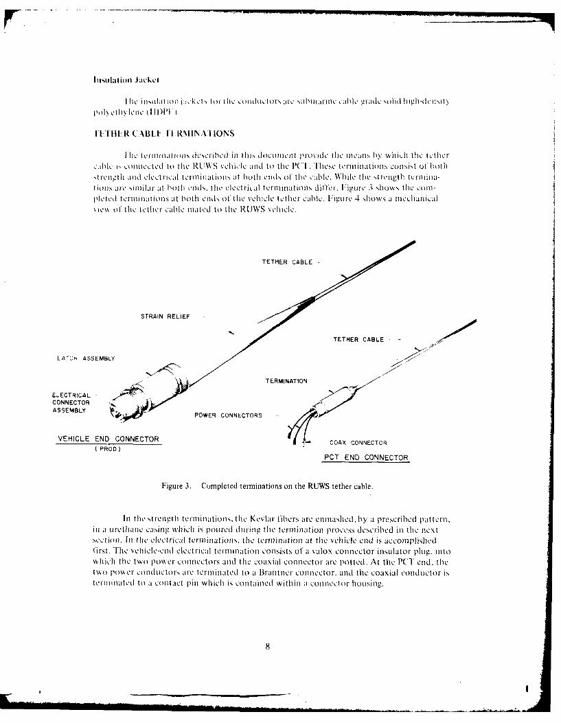
I hi. teriniationis described ill this tLOCIIII)Icnt provide& the iiiCJilm by Which thle tethercablc k~ conlilected ito the Rl.\\S vehicle an1d to thle KAl. "I'es terinalltion, COnlSiSt 01' bothstrcne,-th and elctric-al termlinations at both enids of the ca-,ble. While the strength tcrinia-tiolis ,jIL shiir at both endsI', thle e-lectrical terminations differ. Figure 3 shows. the cornl-plc ted term in ations at both ends OfI the vehlicle tether cablec. Figuiire 4 shows a mechanicalic\k. of t ie tethert I cablec mated (to thle RUWS veI cc.
STRAIN RELtEF
LATCH ASSEMBLY
TERMINATION
E-ECTRICAL-CONNECTORASSEMBLY POWER CONNECTORS
VEHICLE END CONNECTOR - CACONTO(PROD)
CA ONCO
PCT END CONNECTOR
Figure 3. Completed terminations on the RUJWS tether cable.
InI thle strei'-th terminations, the Kevlar fibers are enmiashied. byv a prescribed pattern.in a tire tha ne casing whlichi is potired dutring- the termination process described inl the necxsect ion. Inl the electrical terminations, the termination at thle vehicle end is accomplishedfirst. The vehicle-end electrical termination consists of a valox connector inlIator plu, intowhichi thle two pow&er connellctors and thle coaxial connector are potted. At thle PCT end, thetwo power conduLctor-s are- terminated to a Brantoner connector, and thle coaxial conductor istermiinatedl to a contalct pinl which is contalined Within a1 conne1ctor houLsing.11
8

4 III
ILC)
rc
zF
0
ZZ 2Z

PROCEDURES
This section contains a step-by-step description of the procedures to be followed inthe strength and electrical connector termination and potting of the RUWS vehicle tethercable. These procedures result in four terminations. As was stated earlier, each end of thevehicle tether cable has a strength, as well as an electrical terminatiom. All four terminationsare essential.
Refer to appendices A through H for parts, materials, tools and the preparation anduse of chemical mixtures.
MATING PROD AND STRAIN RELIEF ASSEMBLY
Before the actual terminations are begun, the mating prod (the male connector atthe vehicle end of the tether cable) and strain relief assembly must be prepared (see figure 5).This operation, performed on the vehicle end of the tether cable, consists of molding thestrain relief to the hi assembly. First, the latch and prod must be cleaned and sandblasted,after which the appropriate surfaces are primed. The strain relief mold is cleaned and pre-pared. The prod is then assembled into the mold, and urethane is mixed and poured, formingthe strain relief. The instructions for this procedure follow.
URETHANE STRAIN RELIEF
VEHICLE / PCT LATCH ASSEMBLY
Figure 5. Vehicle/PCT mating prod and strain relief.
PREPARATION
I. Mask all areas not to be potted, as illustrated in figure 6.
2. Sandblast all the exposed surfaces (see figure 6).
3. Using Freon TE-35 or trichloroethylene as a solvent, thoroughly clean theassembly to remove all grease, oil and dirt. (Refer to appendix D.)
10
0/

- - - MASK
SANDBLAST- -
iiMASK
VEHICLE / PCTMATING LATCHASSEMBLY
Figure 6. Masking and sandblasting the mating latch assembly.
POTTING PROCEDURE
I . Mix the primer required to bond the urethane to the metal prod, in accordancewith the instructions in appendix E.
2. Apply primer to the sandblasted surfaces.
3. The strain relief mold is shown in figure 7. Separate the two halves of the moldand clean the inside surface with a solvent in accordance with appendix D.
4. Wipe the inside of the strain relief mold with silicone grease as a mold release.
5. Grease the polypropylene tubing and insert it approximately 2 inches into themating latch assembly from the sandblasted end, as shown in figure 8.
CAUTION
Do not allow grease to get onprimed surfaces.
III
fV

URETHANE INLET SLOTS
Figure 7. Strain relief mold.
URETHANE INLET POLYPROPYLENE TUBINGSLOTS - T WITH HANDLE ....
,i4
MOLD-'j -_- SEAL WITH AUTOMOTIVE
CALKSTRIPVEHICLE / PCT MATING LATCH ASSEMBLY
Figure 8. Strain relief potting assembly.
6. Assemble the prod and strain reliet nold, placing the prod groove in the mold(see figure 8)
7. Install six heating elements, connecting them to the temperature control.
8. Set the temperature control for 150 degrees F.
9. Place one fire brick under each on, of the mold, as shown in figure 9, to
reduce heat loss .
12

STRAIN RELIEF MOLD-
(a)FIRE B3RICK
*2"
(b)WOOD w_ -~_JKN
Figure 9. (Chocking the mold ii oi rigOIJ
10. Raise the miold end opplosite tile prod appi oxin mately two inches. as shlown it)fionre- (). chocking it with a wedlge. This will prevenlt anl lir trap forminge within thle mlold.
I I. mix approxiniatcly 05() 1ml ol' P(-1 590 tirelhiane inl accordance with the inl-strttt ills i appenCldix HI.
12. lDerzs the urethane inl a vacuuni ar.
13. While thle Urethane is heing, deiaSsed, 0.-1 torC teMold heater onl. This will prehecatthle mold and( make fillingz easier.
14. Begin p101-1iris Urethane inito tilie slot hiole at the prod end of' the mold. Watchtlie urethane level tliroughl thle hiole aspotirimns P rogresesgd i :l owenring tile molI toalevel posit ion so as to avoid spilli op' UretIILHI anet yetsil preveniting an air pocket formning. atthle prod end~ of the miold. Fill the mold with urethiane to the top of thQ slot holes. At tilee rd I Olthe p)ouring. tilie 1o101d shoulId he level.
15S. CureC thle Mold for1 approx 0\iniattely eight htoars at 1 50 degrees 1F.
16. To fa,,cilitaite remova. demnold the fixture while it is still tiot.
1 7. Trimi as ncessa rv.
13

18. Remove the polypropylene tubing from tile fixture. To accomplish this. firstseparate the urethane fIrom the tubing by holding the handle and twisting tile urethane backand forth. Then, while holding the prod, simultaneously twist and pull the tubing from theprod.
19. Visually inspect the strain relief. Eliminate any voids or large bubbles with asyringe and needle. No curing process is required.
TERMINATION CONES AND HOUSING
Each end of the tether must be terminated. At the vehicle end, the strength termina-tion cone, when completed, is inserted into the termination cone housing. At the PCT endthere is no housing. The two strength termination cones and the termination cone housingfor the vehicle end are shown in figure 10.
p STRENGTH TERMINATION CONE(STAINLESS STEEL)
( VEHICLE END)STRENGTH TERMINATION CONEO(STAINLESS STEEL)
(VEHICLE END)
TERMINATION CONE HOUSING(STAINLESS STEEL)
(VEHICLE END)
Figure 10. Strength termination cones and housing.
14
VEHICLE ENID
Thiis sectlonl p resellt ts list rILICt ionS for the strength te rmnat ion at thK vehicle enad o1the te ther cable. It should be noted. however. t hat the st rengthI terinat ioni at thle j)( end
oii tile vehicle tether cable is identical to thuat for the vehicle end, It will he simpler in theheld to performi both the st ren-t iil anid electrical term inaat ions Onl thle veil e end fi rst t1heniproceed to the PCT end.
The coneC aind ki aLIig are cleanied aind sandblasted, and tile terminaat ion potting fix-tore is assembled. The cable is stripped back and thle streng,,th members separated. Thlestrength members are cleaned and dried: then wrapped to protect themn while thle cable. con-dUCtor-s and Streaig thl meambers are fed into the termnaation cone. Thle cable and cone arethean installed inl tile termination fiXt Lre aaid thle streaigth elements separated aaid Secured illthle fixture top plate. Epoxy then is pouared inito thle conle. deggassed aaid cured. Finally, thleterminaation cone is removed fromn thle fixture.
Pott ing of, tihe termni nation conie and h1ousing is thle final step in this portionl of' tilep~rocess. The cone anid housing are cleaned and primed, and the cone is installed ill thle boos-inig. The housing is then istalled in the mold. anid Urethane is poured into the mold. AfterdegaSSing land curing, thle last step is to fill ally voids which have developed durinig tile process.
The inistructions for this entire procedure are listed below.
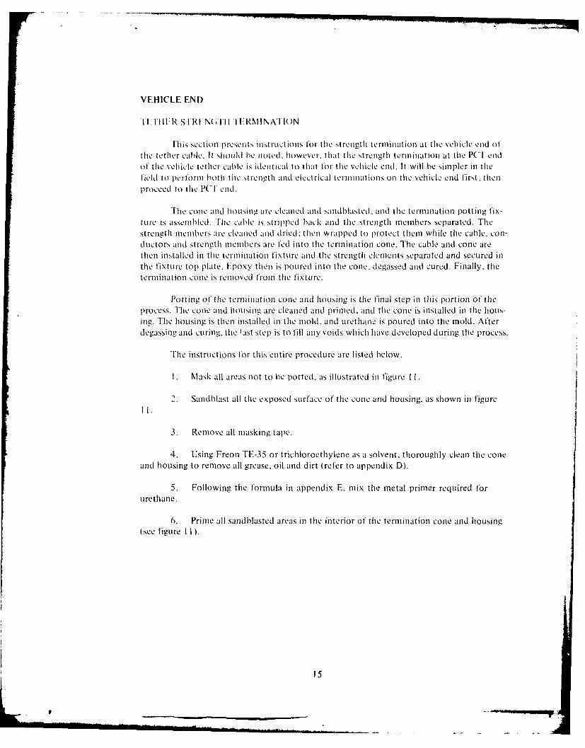
I. Mask all areas not to he potted, as illustrated ill figure I f
2. Sandblast all thle exposed Surface of' thle coine anld h1ousing, as Shown inl figUre
3. Remove all masking tape.
4. Usinig Freon TE-35 or trichloroethylene as a solvent, thoroughly clean thle conleaald housing to remove all grease, oil and dirt (refer to appenldix D).
5. Following thle formula in appendix E, mix tile metal primer reqJuared forUrethane,
6. Primle all sandblasted areas in the interior of' thle termfirnationl cone amid h1ousirg(see figure I I.
Is

SANDBLAST-I
t SANDBLAST-+ -
Ii $-MASK
SANDBAST ASK ASKH
Iiur 11 Makn an adlsigtesrnt enia ncn n osn o h
FIt . 11.c Masin anod onts ableri the stgth th termination n n housing. h
CAUTION
Be certain not to damage the
prod or termination h1ousingduring- the procedures whichfollow.
16

TO VACUUM PUMP
4 VACUUM CHAMBER LID
VACUUM CHAMBER
1 - TOP PLATE
1 -FIXTURE
C CLAMPI, FIBER HANGER FRAME- (HEIGHTS ADJUSTABLE)
- WORK BENCH 10.25 TO 15.50
FIXTURE BASE PLATE
SPLIT CASLE CLAMP
Figure 12. Assembly of the termination potting,_ fixtuji-.
6 EA. EQUALLY SPACED rN2 6 FILLISTER HEADMACHINE SCREW W1
00
0 0
SPCD0p-O LT
12~ EA (lULL SEQACED
CONDUCTOR PASSAGE HOLE
Figure 13. Fixture top plate.
17

- 300 TYP
0 .0 9 3 " - -
-_ 2.3 MM
600 TYP -0.937"0.093" 23 MM
0.750" - -- 1250"19 MM F 31 MM
- M M-"" S P L IT
0.2 5 o ' 0.500 0.750"6.35 MM 12.7 MM 19 MM
MATERIAL: 0.12" THICK ALUMINUM
Figure 14. Strength member element separator ring.
2. Thread the prod and termination housing down the cable approximately 15
feet for easy handling of the cable during termination.
NOTE
Plant pruning shears are recomnmended forthe next step because, unlike normal shears,they have only one cutting blade. The secondis a flat surface against which the materialbeing cut is forced. For this application,such shears have been found to he ideal, notonly because they are usually sharper, butbecause they provide more leverage.
3. Cut off the damaged end of the cable, using a turning motion around the cableto cut all layers evenly rather than attempting to make a single cut through the layers.
4. Measure 10 inches from the end of the cable: then make a mark around thecable at that point using a tubing cuitter with slight pressure.
5. Bend the cable slightly at the mark to improve visibility of the work area: thenremove the outer jacket with a razor, being careful not to cut thc inner elements.
6 . Unwind, cut and remove the chase tape 0.250 inch from the outer jacket.
18
, __.___ ..
7. Unwind the strength member carefully.
8. Unwind, cut and remove the inner chase tape as was done in step 0.
9. Cut and remove the thermoplastic rubber fillers and nylon monofilament core(see figure 2).
CAUTION
Do not nick the conductor insulation.
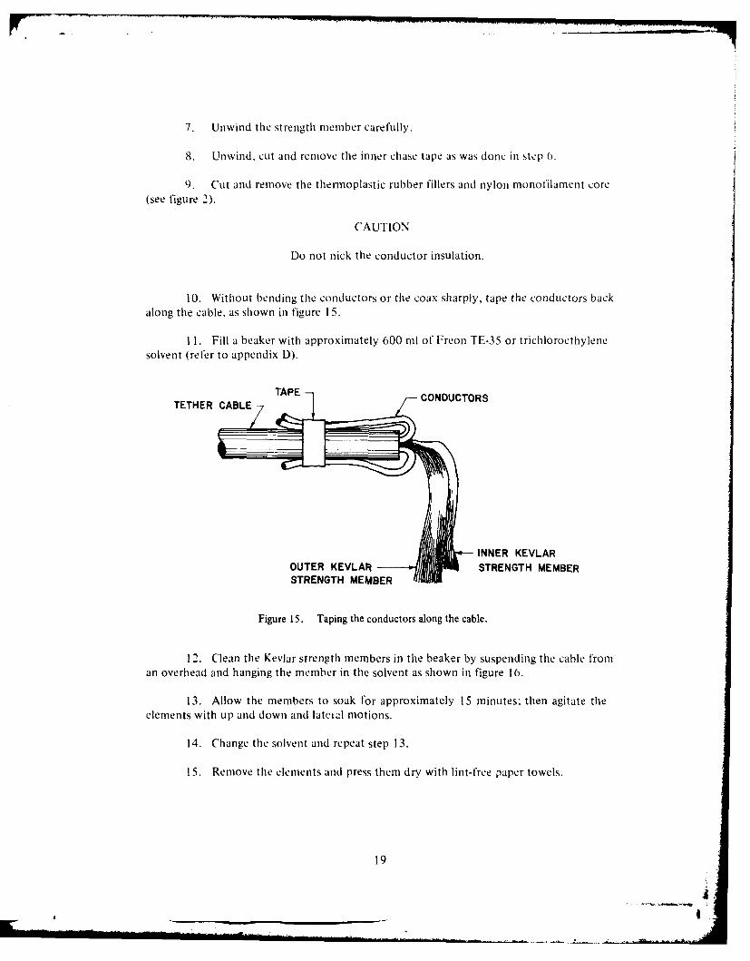
10. Without bending the conductors or the coax sharply, tape the conductors backalong the cable, as shown in figure 15.
11. Fill a beaker with approximately 600 ml of Freon TE-35 or trichloroethylenesolvent (refer to appendix D).
TAPE CONDUCTORSTETHER CABLE/
INNER KEVLAROUTER KEVLAR STRENGTH MEMBERSTRENGTH MEMBER
Figure 15. Taping the conductors along the cable.
12. Clean the Kevlar strength members in the beaker by suspending the cable froman overhead and hanging the member in the solvent as shown in figure 16.
13. Allow the members to soak for approximately 15 minutes: then agitate theelements with up and down and lateil motions.
14. Change the solvent and repeat step 13.
15. Remove the elements and press them dry with lint-free paper towels.
19
.... • . . . . ,., _' [i i i l ._ _ J .. . in ........ . . i nmlu iI~ i . . . . , . ... I

ETHER CABLE
-TAPED CONDUCTORS
-4 -FREON TE -35
KEVLAR STRENGTH MEMBER
BEAKER
Figur 16.11e g the strength member efernents.
10 Allow tile elmnstai d r utinimuini o! two hours.
( *A L UlON
Protect tile elements trout contiminl't onduringt air dryinL.
i7 . lIn further protect tile outer strenetli nietu1her- eleiiieiltt 1101in01 .otaill atoll,wrap themi with an 8-'x I I -shieet of' paper. as shown in tlcur 17.
18 ChIteck t he fiber wrap coomingi out t'rom the side of- the cable. Avoiding a possi-bie cross. d i~de thle f"ibrs as shownin ;1 Cii re I 8.
P). Dijvide 1he iner fiber into three (L1 qual , 1part 1 then trther 1% ide ech,~ Of' thlethlrie parts inll I11. so that there is atotal of, six equal parts.

- CONDUCTORS
ISOLATED OUTERFIBER ELEMENTS
CELLOPHANE TAPE INNER FIBER ELEMENTS
8"X I1" PAPER- -.
Figure 17. Isolation of the elements.
20. Wrap the end of each part with small gauge soldering lead.
21. Using cellophane tape, number the six parts 1-1 through 1-6.
22. To protect the inner strength member elements from contamination, wrapthem with an 8-x II " sheet of paper as shown in figure 17.
23. Remove the paper wrapping from the outer elements: then divide them into 12c(ual parts. as was done for the inner elements in step 19.
24. Wrap the end of each part with ,small gauge soldering lead.
25. Using cellophane tape, number the 12 parts 0-1 through 0-12.
26. To protect the outer strength member elements from contamination. wrapthem with an 8"x II" sheet of paper, as shown in figure 17.
27. Remove the conductors from the cable.
28. Pass the conductors. elements and cable into the strength termination code, asshown in figure 19.
21

p TETHER CABLE
-ISOLATED OUTER FIBERINNER FIBER--CHECK FIBER WRAP
FOR CROSS OVER(a)
INNER
DIVIDE FIBER INTO -6THREE EQUAL
PARTS GROUP
b) WIND THE END OFt FIBER WITH SMALL
DIVIDE EACH OF111 GAUGE SOLDERING
THREE PARTS 5JflL II LEADINTO HALVES
(c)
INNER FIBER: SIX (6) EQUAL PARTSOUTER FIBER: TWELVE (12) EQUAL PARTS
Figure 18. Dividing the elements.
. O". 500 I
CONDUCTORS AND
FIBER ELEMENTS TETHER CABLE
ELECTRO SEAL
STRENGTH TERMINATION CONE
Figure 19. Sealing the termination cone and cable.
22

2) Apply a 0. 50-inch-widc bandl e clectro mcal aru the cabic jacket at tielocation between 0.250 inch and 0.50 inch 'loiii the cud of tle jacket (see figure 19).
30. Pull the cable back into the strcngth terminlation conte until approximately 0.50inch of' the cable jacket portion remains ill the conc. Apply a twisting motion between thecone and tile cable to achic a good seal.
3 I . Wipe excess electro "Cal ftrom the portion of cable jacket which is outside thestrelgth termination colc.
CAUTION
I landlk tle cable with extreme caution
d lurilI- the following steps. The cahle endill the strength termination cone is easilydaniageI t this point in the operation.
32. Pass the strengthIi termination cone and cable end Up th IIrough the base plate ofthe termination fixture assembly
33. Install half of the split clamp on the underside of the square hole in the baseplate.
34. Place the cable in the split clamp and install tihe other halt of the split clanp,leavin g approximately I inci between tihe bottom 01 the cone and tile split clamp.
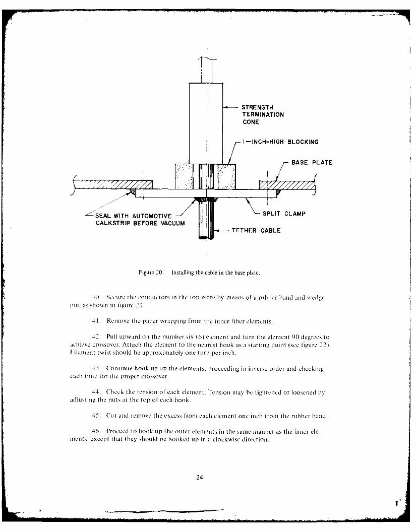
35. Insert two pieces of I -inch blocking material between the strength terminationcone and the split clamp, one ont each side of the cable, as Sholwn in figure 20.
36. Recheck the strength termination cone and cable, especially the outside deal.to be certain they have not been loosened.
37. Tighten the split clamp.
38. Bind the three conductors together with three rubber bands. One band shouldbe placed just above the top of the strength termination cone: one at a point halfway be-tween the strength termination cone and tile top plate: and the third just below the topplate (see figure 21).
3). Pass the conductors through the center hole of the top plate.
23
STRENGTHTERMINATIONCONE
I I-INCH-HIGH BLOCKING
BASE PLATE
'I >I.**
_: SEAL WITH AUTOMOTIVE -\ SPLIT CLAMPCALKSTRIP BEFORE VACUUM TETHER CABLE
Figure 20. Installing the cable in the base plate.
40. Secure the conductors in the top plate by means of a rubber band and wedgepin,. as shown in figure 21.
41. Remove the paper wrapping from the inner fiber elements.
42. Pull upward on the number six (6) element anrd turn the element 90 degrees toachieve crossover. Attach the element to the nearest hook as a starting point (see figure 22).FilamCnt twist should be approximately one turn per inch.
43. Continue hooking up the elements, proceeding in inverse order and checkingeach time for the proper crossover.
44. Check the tension of each element. Tension may be tightened or loosened byadjusting the nuts at the top of teach hook.
45. Cut and remove the excess from each element one inch from the rubber band.
46. Proceed to hook up the outer elements in the same manner as the inner ele-ments. except that they should ne hooked up in a clockwise direction.
24

CONDUCTORS
TOP PLATE-
______________RUBBER BAND
WEDGE PIN
ISOLATED FIBER ELEMENTS
TERMINATION CONE
Figure 21. Stringing the conductors.
RUBBER BAND
/ FIBER ELEMENTS
(a) (b)(c
Figure 22. Rubber band attachmient to the element.
25

47. Install the inner strength nember element separator ring, opening the split sec-tion of the ring, passing it through the conductors to the center of the ring, and then bendingthe ring back to its original state. Place the elements in the separator grooves, as shown infigure 23.
48. Again check the elements for proper crossover.
49. Install tile outer strength member element separator ring, as was done for theinner ring in step 47.
50. Position tile separator rings so that the elements have the proper angle withintile separator cone.
-CONDUCTORS
OUTER ELEMENTSSEPARATOR RING
INNER ELEMENTSSEPARATOR RING
OUTER ELEMENTS0.0625" AWAY FROMCONE INNER WALL
INNER ELEMENTS
0.125" AWAY FROMCONE INNER WALL
TERMINATION CONE
TETHER CABLE
Figure 23. Positioning the element separator rings.
26
e • "7,

Pouring. )egassing and Curing Epoxy
I. Using automotive calkstrip, seal all joints in the split plates, cubic, cable clam p
and any thru-lolt links (see figure 20).
2. Iix 100 ml ofepoxy and degas it as described ill appendix (.
3. C'arefully pour the epoxy into the termination cone. filling it to a point just be-low the edge of, the slots in the side o the cone.
4. Place the plastic vacuuLm chamber over the fixLi re, applying silicone grease to
lie sealinlg surfaces, as shown in figure 1 2.
5. Attach a vacuum line from the Pump to the chamber.
0. Begin evacuating the fixture, watching for bubbles in the epoxy. If bubhles be-come excessive, causing the epoxy to spill, release the vacuun.
7. Check for leakage at the cone and cable; then cycle the vacuum several times.
holding at a vacuum of 28.5 in/hg (724 mil/hg) for approximately five minutes in eachcycle.
CAUTION
The vacuum may pull tle cable into thefixture and loosen tile elements. If thisoccurs. release the vacuum, loosen the
cable claip, and pull the cable back toits original position. To prevent suchpulling and loosening. attach a weight(20 pounds maximum) to tile cable,
as shown in figure 24.
8. Remove the vacuum Lchamber and check the level of the epoxy to be certain
the cone is full. It tile cone is not full, add more epoxy.
(). Allow the epoxy to set for approximately two hours belore applying heat.
10. Install two infrared lamps on either side of the fixture, 18 inches (46 cml Iroill
the epoxy-filled cone. The heat may be controlled by augmenting the lamps with reflectors:then moving the lamps and reflectors as needed.
1 I. Place the tip of a dial thermometer on the surface of the epoxy so that it is justtouching the surface.
27

TO VACUUM PUMP
VACUUM CHAMBER LID
VACUUM CHAMBER
FIXTURE
b--
TETHER CABLE
0.250" NYLON LINE
20 POUND ANCHOR WEIGHT
Figure 24. Fixture evacuation.
12. Tape the thermometer to the fixture.
CAUTION
Never exceed 175 degrees F (80 degrees C).The conductor insulation jacket will softenif it is overheated during the cure cycle.Refer to appendix G for cure cycle instructions.
13. Re,:'ove the termination cone from the fixture.
14. Using caution not to damage the conductors, cut off all the elements at the tot)surface of the epoxy.
Potting the Termination Cone and Housing
. Clean the cone. cable and conductors with Freon TF-35 trichloroethvlenc sol-vent. This is considered to he the most suitable solvent, since it will not damage the insulation.
28
e II

2. Mixnmetal primier. as, described in appendix F.
Prime all exter-ior stirtfaces Of tile teri11llion C011C CXcCept the channel oroovc.
4. Prune the nose of' the termination housinii.
~.Usinug Freon 41>35 or trichioroethylene solvent, clean thle cable for a distanceot' three inches from thle Cone.
0. Prime the cable with nonnmet allic primer, as described in appendix F.
7. Allow all primied surf'aCcS to air dry.
S. (lean the termination houLSill- potting mold, applying siliconie grease as a nioldrelease auent.
9). ( enlt]V puLsh thle ter'minion1 Cone inlto thle ho0Using.
10. VOrce a small amount o1f electro seal into tile space between the Cable and thlenose of' thle houLsinlg to prevent leakage throu~gh to thle termination cone (ee figureC 25 I
TETHER CABLE
NONMETALLIC PRIMER3 INCHES FROM THE CONE
URETHANE PASSAGE HOLE
TERMINATION HOUSING
TERMINATION CONE
-- OIL FILL AND BLEED PORT
CONDUCTORS
Figure 25. Termination housing amid cone.
29

1 . Install the housing in the mold, aligning one of the small int::ke holes with the
conle channel slot.
1 2. rihten the mold bolts and install the bridge clamp over the top of the hlousing.
13. Seal the mold and the housing joint with automotive calkstrip.
14. Tighten the bridge clamp evenly to fore the hoursing to the bot tom of therecess in the mold and keep it in place.
15. Suspend the mold from an overhead at a comfortable working height (seefigure 26).
0.250 - INCH NYLON LINE
- CONDUCTORS
- BRIDGE CLAMP
--- TERMINATION HOUSING
0.250" DIA. THREADEDSTUD AND NUT
MOLD
- URETHANE INJECTION HOLE
WITH PLUG SCREW
-- AUTOMOTIVE CALKSTRIP SEAL
-.-- -- TETHER CABLE
Figure 26. The potting setup.
30
I.
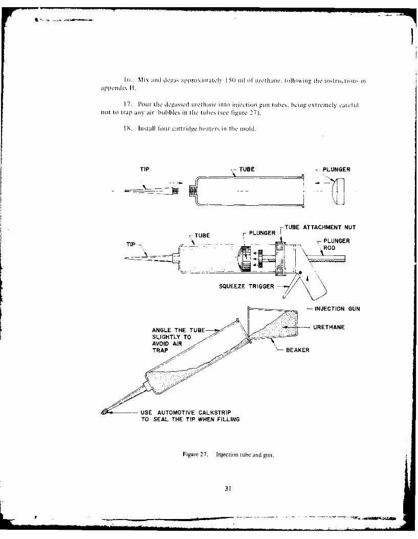
apen 0 ~. MIix aiull degas approximiatelv 15 1(1 of' ol rethanle. t'ollowing thle instr1Ict nN iII
I17. PuLr tilie degaZSSed urethane1 inlto inljeCt iOn gunll ILuheS. being ext remnely caref ulnot to trap any' air huh bbleS in thle t iibeS (See tigure 27).
18. In1Stall 101,11 CMari(II de heatrS in thle mo10d.
TIP TUBE ~-PLUNGER
7-TUE PLNGER TUBE ATTACHMENT NUT
TIP~ -- - PLUNGER
0
SQUEEZE TRIGGER
LINJECTION GUN
ANGLE THE TUBE-- URETHANE
USE AUTOMOTIVE CALKSTRIPTO SEAL THE TIP WHEN FILLING
Figure 27. Injection tube and gun.
31

1 1). 1 Istall thle Controller senlsor ad lhook 11tite Wires ill p~aralle-l ilil.!- "~ ireC iilts,.
N). NN 111le th~ ieth1-Ie)I is beineL Lleasscd. turn 1 tile heater conitrol onl and set it forI Mt) ileuees I , t( deuerees C)I. This wvill preheA tile 1o0Ld and IMIke tile tilling" eaSie .
I1. Inljct tile Urliaiie11 through11 time imieetion hole located in the miold. Fll slowlyuntil thle uLiam1111e tiows trout11 tile ehamimell eroove%' A tile streiigtli teruimiation eoneC. Ensurethat the conec is 1lull to the top.
22 Check ftor leakac around thle cable aind 11old.
3.Whenl thle mold is full and free 01' bulelIS, install a ,erew as a pil" ill thle injee-tioli hole.
24. Inurn thle con tlm0le r (ill and reuIiove tilie sensor and heaters.
2.Remlove tile eompIIletCd tem niat ion assembly while the mold is still warm.
'0. Remove tile biuCelamii p.
27. Remove thle mold hol ts and inlst all t hem inl the four thIireaded jacking holes.
28. Turn achi Jacki ng bolt 1 /2 turn at a timle until the mold separates, into twohalves.
2 9. Work thle Cable anmd 11ousill- ni.nt v uint il they conic free of' thle mold.
30. Inlspect thle eomple11ted assembly11 for voids or bubbles.
31I. Mix approximately 25 1ml Of Urethane, inl accordance with the instruct ions inlappendix [f.
32. Add 10 percent IEIK ( mnethylethylketone): then degas thle mliXture.
33. Check the mlixture to see if' it is thill enoug1h11 to be used in a small syringe with alarge needle. If' it is too thick. add more NILK in sinall amoun111ts until it reaches thle desiredcoinsi stenitcy.
34. Fill the syringe with thle mlixture, install thle largest needle, and puncture eachbubble, filling the void with thle urethane mixture. A temperature cttre is not required.
TETHER ELECTRICAL TERMINATION
This section presents instruictions for the electrical termination at the vehicle end of'thle tether cable. Thle operation is begun by cleaning the conductor cavity. Thle conductorsthen are cut back, thle insulation stripped, shrinkable tubing irtstalled. and power socketscrimped in place on the conductors. Thle center conductor is then inserted into thle crimp
32

bhtrlel. Tihe critlp support sleeve is installed ol .I(10wcd by tile split tcl lon grolilillict I. Ili cr-
niinatcd incr Contact asscmnibly is then inserted into tlic crimp support slcvc and ilic s-cCcis crimipcd. I lie slirinkable ttibiliic Is Shrlunk inlto pla.c. Mnd t lic connciors are iinstalled inl
tilc VAlX coiiiicc-tor inlator ptlug L11w l inl"1ator Str-ipS airc inllZ1Cd inl tile houLSingc anld nr-than11c is poiircd in ((Itilc p)lug1. dIcgaZSCdI and curcd. T'he p)lug is tile]) in1StalIcd ill tilec hou1singL.Fi-allv . tilie trillonationl Iimtiis1,I'S. is sciiihlcd to (lie prod. Thc inlstruc.tilo (Jrhis ciitir-cp roccdn ~rc ar-c listedc hclow.
I . RCHIioC any urcthlanc drlip)s i1- spills.
2. (Ican tilc conduLctor cavity thorougl1y W ith Frcon -11,-35 or tricholorocthy Icuctak ing carc to io0\e tilic cond Lctor-s as litl U s p)osSihic.
Se. 11c1-li.1rC 28 for an1 illuIstratcd hr-cakdown of' clcctrical tcrmination parts.
POWER SOCKET (FEMALE)DEUTSCH No. 800-12/30-3
VALOX CONNECTORINSULATOR PLUG
OIL PASAGECOX SOCKET (MALE)OLEPSAG DEUTSCH No.0107-001-000
Figure 28. Electrical terminaion parts.
4. Mcasurinii, from tilc sUnrfacc 0 th)c tcrmlinaionl hlousing. cult thc powcer and co-axiA conductors to a lcngthi of, 1 .250 inchics (25.4 cii).
5. Using a k nife. cut aroi nd tilic ilnso ait ion oft hC power onlduictor.
0. Strip tile inIsulationl triii- tie conduILctor. Icaiu a mmiiinlll ot 0. 1875 inch anda maximum ol 0.1 288 inch of ex posed wire. as shown inl figurc 29.
7. USiiie tice BuIchIaan crim 1)0o1 2 225 20/1 -0) 1 WithI t hc 02 turrct sct f -or si/ce I-2'cllOW100 hoicad tilc Wirc eauHL'C dial sct for ; 14 AWG. install tilec shrinkable tubing oii thc
~o\%c r coid iic.t()r.
33

0.1875TO 0.288--- DEUTSCH No. 800 -12/30 -30.187 TO ~K -- FEMALE POWER SOCKET
SHRINKABLE 14AWTUBE
Figure 29. Power contact.
8. Insert thle DeUtSCh #800- ),1 /30-3 fentiale power socket into the tool andi crimpllit Onto thle power conduILctor.
(). Using a knife. cut around thle inlIationl o1 thle coaxial cond uctOr.
10. Strip thle in1sulationl from11 the coaxial conduIctor in) accor-dance withi figuLre 30.
0.1250" TO 0.1562" - O P5 " T .1 5
DEUTSCH No. 0107 - 001 - 000COAX SOCKET
RG-5 COA CABE <CENTER CONDUCTORSHIELD AND DIELECTRIC-
Figure 30. Stripping thle coaxial conductor.
1 1 . InstAl the shrinkable tubing onl the coaxial conductor
12. Insert thre D~eutsch m=107-00 1-000 male coaxial socket into thle tool anld crim pit on to thle coaXial conduILctor.
1 3. Place thle inner cotitact pin in the D~aniels, crimp) tool YI 1-800. Set the tool at,,elect [oil 1nmber .
34

14. Insert the center conductor into the contact crimp barrel, enCsuring that nowires remain outside the crimp harrel. The dielectric will be against the end of the contdat.The inner conductor will be visible in the contact inspection hole if the cable preparationand termination are properly done.
15. Place the crimp support sleeve over the dielectric and tinder the outer shieldbraid, as shown in figure 3 1
16. Separate the two halves of the split teflon grommet.
17. Install one half of the grommet into the support sleeve bore, pushing the grom-met half into the bore Until it snaps behind the contact shoulder.
CONTACT SHOULDER
F-CRIMP SUPPORT SLEEVESHIELD
~CRIMPING SLEEVE
INNER CONTACT
*DIELECTRIC
- SPLIT TEFLON GROMMET
~APARATE
Figure 31. Coaxial contact assembly.
35

\Ic boh rolilillict l~lC ICntil
[1iC ,ol l I0L1dCl' niti',,t liC fIll\ CX ll),sC(l
q* i 1-, )4 opciiveid %vrcnch: to hloldl IlW suppor)01t 'I1CCC. inSert tile tcr-liitedinnicr conitact assellibl\ Into tilec kCr-111p 1,uppor01t sIVC\ C to I 0-inchI-p)ould nila\ii])lltl tor'(LuC.
CA.U\I ON
I)o not turnl t he cri iip support ,Icc\C
oil tile CJbiC durIingL this Ass1C]IIlblv.
,0. ('silu [liC Bultim~lan i i-o~nago l cimnp tool M2291I0'7-1 with dic inlilllCr
MS226 1( T-1 '. pushl tilec rillpingL SICCXC OVCl tile C~lp0Cd oLtVI- Nhicid braid and bUtt it
- lsVrt thC 1,iseibIV inlto tCi upp~r (li C"B" at thecCrimp s5ICCV and crimp it.
Trim enIlCxcess fronm th hie11i~d braid wVires. it' nccessm- I. Tile shhid b raid \\ lie',
1,111,ld nlot C~teild on1tO tiW ShoLildCr' 01*tfl h' oItCr bodV.
23 I idV tile sh ninkab IC t ubil"Im oCr- t IW I CC\ C o I'Ili oiW C tactI. ( For t I I power COnII-
taict. slidC thC tubhing Over tlhC Crimp barrel. I
'4. ('aretuLllk shrink tile tubingi inl piaCC.
2.install the coliiICCtol's inl thlC valox cojneCtor insulator p)lugI, pusingil tICI inl
u n1til tllesna inlto plaICC. Tjhey Shoutld he HuIsh onl til hr aCC side. as sh~ownl inl figurIC 2 8.
26.Istalll tile ilISuilator strips inl tile houIsing. Ih~ should fit snIII gly ad not1 pr-trrudC ZaboVC tile nulaktor SIC p.
7. aupn 1 ~ula o iuin r n m0' vrhicad. as shown in fiiurc 32
,8. Mix approximfately 25 l 01 o tirCiluC fillowing t1W instruCtions ii appenldix 11.
2 POur tile degaSSCd ur11tltauC intO0 tile XaIox C01nuCCtor- inIsulator p)lug, using a mlix-n.- rod or SCreWd rjver to transh'Cr tilhC tlWthaC to tiC le g a)L11 little at a tinlIC.
30. Install two inflrared lamlps oil ci tlivcr sidC oh, thC valox Connctor plug. approxi-
inately 18 i nChis (40 m in t romt thi r.1CI ha1C-lil led plug. (ontIrol th lire1Cmpcrat urc by movingtile lamps ais necessary.
36

CONDUCTORS
01
1
TETHERCABLE
URETHANE FILLED
-VALOX CONNECTORINSULATOR PLUG
OILPASAGEHOLETERMINATION HOUSING
CONDUCTORSVALOX CONNECTORINSULATOR PLUG
Figure 32. Valox connector insul~lator plug potting.
31. Install the valox connector inlator- p~lug ill tile houlsin2.
32. Rotate thle insuilator aid condulctor 3U 00 l erl-CeS whllile insert ing t lic il i the
CAUTION
D~o not use excessive force. The tl uruling
shoul-d 1t01r1i thle conductors inlto a Serviceioop behind thle insulator inl thle cavit\y.FMnsure that tie inSullator seats Onl thlealipitnmen t pinl ill tile hotising.
33. Inlstall thle rtainlie nariig
37

34. Slide the termination houtsing into the prod and rotate it until the threaded fillport is visible through the access hole.
35, Install tile sealing screw. File termination must he filled with oil when it is in-stalled oil the vehicle.
PCT END
When the termination is complete at the PCT end, the tether cable connector is in-serted through a holddown clamp and secured to the reel by means of the transition tubing,as shown in figure 33. The specific termination instructions are contained in the followingparagraphs.
COMMUTATOR CABLE
-- ELECTRICAL CONNECTORSTRANSITION TUBING(OIL FILLED)
WINCHPCT END CONNECTOR
HOLD-DOWN CLAMPTETHER CABLE
Figure 33. Cable connected to the PCT.
TETHER STRENGTH TERMINATION
The strength termination for the PCT end is the same as for the vehicle end. There-fore. the step-by-step procedures followed for the strength termination at the vehicle endshould be followed here.
38
_____i:

a
TIlIER ELECTRICAL TERMINATION
This section presents instructions for the electrical termination at the PCT end ofthe tether cable. Figure 34 illustrates the completed termination. To achieve this, first theconductors are cut and insulation stripped back. Shrinkable tubing is installed, the pins areinserted, and the cable connector is assembled as shown in figure 35. The step-by-step in-structions for this procedure are listed below.
TETHER CABLE
STRENGTH TERMINATION CONE
POWER CONNECTOR
COAX CONNECTOR
Figure 34. Completed termination, PCT end.
39
SHRINKABLETUBING - " 0 3125
- 22 - 18 (RED) INSULATED BRANTNER RMA- FP
SOLDERLESS BUTT CONNECTOR CONNECTOR
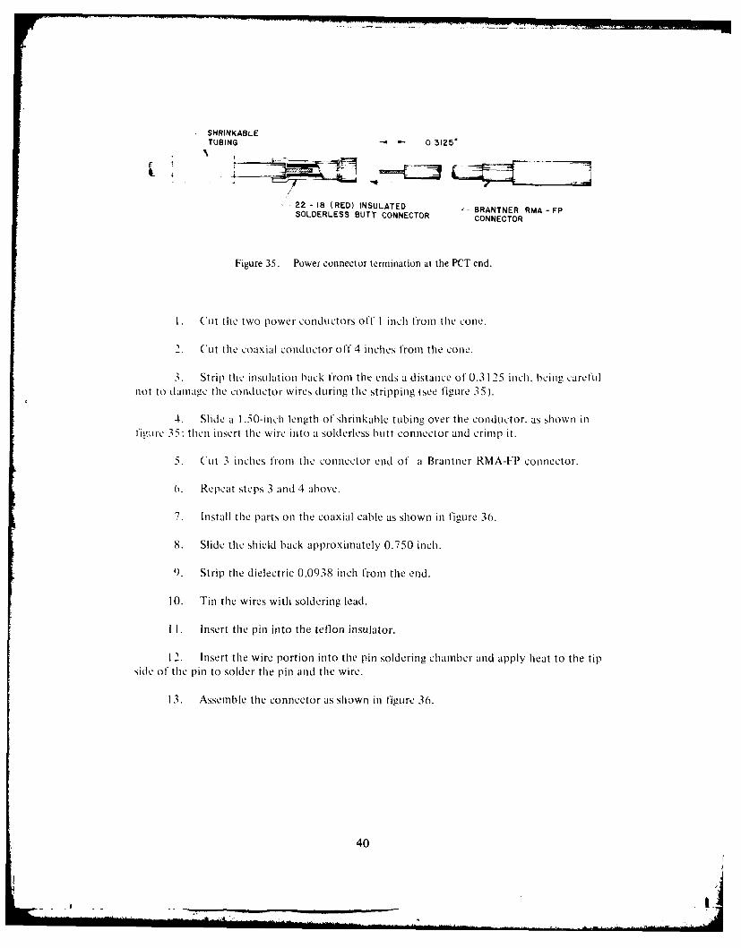
Figure 35. Power connector termination at the PCT end.
u. ('Lit the two power conductors off 1 inch from tile cone.
2. ('it the coaxial conductor off 4 inches from the cone.
3. Strip the insulation back from the ends a distance of 0.3 125 inch. being carefulnot to damage the conductor wires during the stripping (see figLire 35).
4. Slide a 1.50-inch length of shrinkable tubing over the conductor, as shown infietire 35: then insert the wire into a solderless butt connector and crimp it.
5. Cut 3 inches from the connector end of a Brantner RMA-FP connector.
0. Repeat steps 3 and 4 above.
7. Install the parts on the coaxial cable as shown in figure 36.
8. Slide the shield back approximately 0.750 inch.
9. Strip the dielectric 0.0938 inch from the end.
10. Tin the wires with soldering lead.
I I. Insert the pin into the teflon insulator.
12. Insert the wire portion into the pin soldering chamber and apply heat to the tipside of the pin to solder the pin and the wire.
13. Assemble the connector as shown in figure 36.
40
-I - ___ ____ ___ ____ ____ ____ _ B

17-
z
w
wh 0
w
CtJ IXJ
C,, 4
-i0I-
-Jw..
0 W 0
oi x
00Ui
4! I

IZE FEREt-NCES
MUnimery, 11. L. and G*. A. Wilkins. Procedures for the TIernmination and Potting of theRUWS Vehicle Tether ('able, NUC TN 1 68 1, March 1976.
2.Gibson, P). T., F. G. White. G. L. Thiomas, 11. A. Cress and G. A. Wilkins, Evaluation of'KEVLAR-StrenigthlenCd Electromechanical ('able. Proceedings of the MarineTechnologySociety I10th Annual Conference. p. 1 70, September 1974.
3. Wilkins. G. A.. Pert'ormiance Characteristics of KEVLAR-49 Tension Members. Proceed-iin,,s of' the International Coitfrence onl Composite Materials. Geneva. Switzerland.April 7-11 . anoU Boston, Massachusetts. April 14-18, 1975.
4. Wilkins, G. A., lDesigns for Neutrally BuIoyant MulticonduICtor Cables, Proceedings of'MITS-IEEE- OCEAN '75 Symposium. p. 121,. September 1975.
5. Wilkins. G. A.. J. D. Hlightower and 1). M. Rosencrantz, Lightweight Cables for DeepTethered Vehicles. Proceedings of' MTS-lEEE OCEAN '75 Symposium, p. 138,September V-)75.
6. Wilkins. G. A.. P. T. Gibson and G. L. Thomas, Production and Performance of, aKEVLAR-Armlored Deep Sea Cable. Proceedings of MIS-IEEE OCEAN '76 Symipo-sium. p. 9A, September 1976.
42

APPENDIX A: TERMINATION PARTS
The parts listed here are required in order to complete successfully the procedure."outlined in this document.
1. Prod and strain relief assembly.
2. Termination cone (vehicle and PCT).
3. Termination housing.
4. Insulation strip.
5. Valox connector insulator plug.
6. Female contact Deutsch #800-12/30-3 (2 required).
7. Coaxial contact Deutsch #0107-001-000 (1 required).
8. Snapring (insulator plug retainer).
9. 22-18 (red) insulated solderless butt connector (2 required).
10. Brantner RMA-FP connector ( required).
43

APPEND)IX BI: LIST OF MATERIALS
The ma terials l isted here a ie rcq ii cd to coin plctC SUCCcSSfu ly t he proccdurcNS ou-t-titled in this document.
I1. Ulrethane, PRC- 1590 or P1W-I 592.
2.Primers for UrCthance:
a. Mctal primcer. PR-420
b. Plastic primcr, PR- 1543.
3. Trichloroethanc.
4. Freon TL-35.
5. Mcthylethylkctonc (MEIK).
6. Siliconc grease (mold relcasc).
7. Bcakers (50, 400 and 000 ml).
8. Linit-free paper towels.
9. Acid brUSh1cs.
10. Flcctroscal.
1 1. Automiotive calkstrip.
12. Epoxy:
a. Resin: Reichold Chemical, [ic. 37-137
b. H-ardener: Reichold Chemical, Inic. 37-620.
13. Masking tape.
14. Cellophane tape: Scotch.
I5. Rubber bands.
44

,XPPLNI)IX C: LIST OF FIXIIJRLS AND) TOOLS
I11w IiMturC> Mid 10ook listCd licrc are reqirel-d to Complete stmccest'tlly 1hC proce-dUr-e\ oLittlucd ill (Ilk' do)tLllcu mcm
I. \orkhemicd).
. 'Iotp platc
d. split clamip
e. I lemiemit separ-ator. ring".
clamnips.
4. Bell jair: p~lexiglass tube.
Bell jar: top plate.
0. \a~cuumiil pump111 With 1/!4-inch ((.35-mm I D tygomi tUmbinm.
Hecater.
~. I Icater elemnents.
T. hermonmeter.
10. IMiXillA r-odS.
I. M Nolds:
a. Mrai clictf
h). Trerm i rutiom hIouSing.(
12 . ImjCtionl 11old 'Pin with cartridge, cap and tips.
1 3. Sy ringe and1L icedleS.
45
To.

14. Crimp tools:
a. Buclhanan crimp tool M-22520/I-01
1. D niels crimp tool MIIO0
c. Bucha1an hexagonal crim p tool M_229 10/7-17.
46
A0

APPE-NDIX D): SOLVENTS AND) THEIR USES
Freon TF-3 S is Used to soak the Urethane from the strength member elements. Inaddition, it is usCLd for cleaning in situations where a stronger solvent Would Cause damiage.
Trichioroethane (chlorethane NU or trichloroethylene) is used to remove the voidfiller compound and Some Urethane from the strength member elements. Also, it is used I-orcleaning- and degassing. However, caution must he exercised in the latter cases since damageto the conductor insulation can result.
MFK (methyleIthylketone) is used for cleaning metal parts before the primer isapplied. Its primary use is for thinning the urethane to be used in filling the bubbles.
Acetone is used for cleaning metal parts before the primer is applied. It may be sub-stituted for ME K for cleaning ptmr1pOeSS only.
N OTi
D~O rot utms acetonec as a th in nerfor filling. bubbles.
47

.XPPENI)IX L: LIRLTHANI METJAL PRINILR MIXING INSTRUCTIONS
Material: P R-420 ( Prod Ucts Researcli and Chemical C'orporat ion).
Ihlloro uughtI mix one part o1 Part A with six parts of Part B by VOIlme. Do not mlixmlore dhaln call he used within a tour-hour period.
BruSh1 a tlhi :i fiiin o I i\ed IPR-4 2( onl all inside surfaCcs of COn nctor-s and Onl wire.i)t not onl the insulation. Let thle primer dry for one hiour at 75 degrees F (22 degrees C).
It the primer becolie, onltamlnated. reclean the primed surface lightly with mnethlyl-e t h Ike tone (\I FK and dir\. St rip pi ng the primer from the connector and reprim ing is notnlecesslar.
48

APPEDIXF: USE 01 NONNMLTALLIC PRINILR
Nhiacral: PR(-l 543 Prodticts Rescarch and Chemnical (Corporation).
lo obtaiji -,oodt adhioni. HIC dllICC shoitid he indc tiAc \k itti mcn lictict\ IkcioncCNIIK V Apply~ a thin coat o1 PR- I 543 it) the tiAcitied surak h\ hrnl~l anld allokk to dry, for
-(0 liInnte, A room11 tclnperattlC. It pr-iICd SUnrltCCN b)C ouIIC c'OltaliinatCd Ihtor* jpottinliv or
Illldlw"huf~he prirred s~rtaCc Withl, a ,oitAhtc! ahiakVc Mnd rcappt\k a thin) oal of PR-l 543.
49

APPI.NI)IX G: EPOXY MIXING. IAi(ASSINt, ANID CURL CYCLE,
Materials: RcikhOld (Alil,111C. 3,-12 " es inlReiChOld ( 11eiiiiCAl. 1ii. L,~ t I 1Laid. Cr
%li\ thle Nreon and aifdcneIVf wm in tio of I 00 parts resin to 50 pairts hardencl.
Pour1 tile nii.\ inito a beAker la\ ig A leasht tViCe t11C capa city' 01 tile JiliOLint of'
P~lace tile beaker inl tile \LAcIiiiin hCHell ar ad evacuateC tiiitil tile MiXtiniC bInsL1 t0bule1. 'Ihi-:d 11d \ 11,1\iae to be repe)aed svclciaI times.
NO]' I
D~O not1 allo\V tile mliXture- to overlIOW thlebeaker. It mlay be necessary to close Offthle pump11 With a valve and allow air to Hlow1b ack into the bell jar to stop violent
'Whenl it is possible to iiainitainl a flnih VaeInL~l onl thle bell jai- anid on1'ly a fw salbblsremlain. thle ep)oxy is on tgassed and1L is ready' to he )oII red in to tilie tem-nat iOn conle.
Fpoxy- may he cLred at 77 delcrees F ( 22 degrees (C) for 15 honurs. or- for 4 hours at1 '70 deurees F (68 degrees C'I.
50
APPEND)IX HI: LJRLII-IAkNI: ,IIXIN(;. I)L(;.A*SSIN(G AND CURL CYCLE-
M\aterial: IPR(-159() or 1 592 (Products R. search and (i1cinica ('01p1o1,t10o))
HEALTH PREC ALU ONS
PRU- 591) hias pannnf to he a safe iiatciiai to handleI when reasonahi c am is oblonOrdinarl-iv giCn ic prinici ples. Such as %Vash inc1 t he cohcipound from thle hiands bc folc cat n),or smoking, shoulid be Observed. I kindShhon Id be w.ashed withi a waterless cleancer. tollovocdlby soil) and water. A% 0 d breat iing vapors. prolonged contact wit Not i skin. con act "o Allopen breaks in t he skin, and ingest ion.
MIXING INSTRUCTIONS
NOT-,
D)O not Open containers Luntil readyto use.
Part B solidies when it is kept ait temperatures below 65 degrecs F ( 19 deec Cifor prolonged periods. Whenever this cond itn N ISncoun tcred. looscn the lid and w-armn PartB to 1 20 ±50 degrees F (44.5 ± 6 degrees C). When warmitng the material. use a tliernio-meter to determine the actual materiial telliperat ie. LQLe abct ion is compee w e teMmaterial loses all of its opaqueness and becomes clear. St irring is essential during I iq tieac-60ll to Provide a uniform materall and to lWsten meltinrg. After I q nefact on. P'art B w illremain liquid ait room temperature.
Part A may solidify partially when stored for prolonged periods below 65 degrees, [:19 degrees C). Whenevr this condition is found. loosen the lid and war-n Part A to 220
10 degrees F 1102 ± 6 degrees C). Do not heat over 230 degrees F 1 10 degrees C L W\henwarming the mnateriA. use a thermomete r to determ inc thle actual material tem pe ratie.Liqute faction is comnplete whlen the material beconmes smoothI and uif orm in appearance anidloses all signs of graiininess. Stiring is essential during Iicquefaction to provide a uniloril lIla-terial and to hasten melting.
D)EGASSING INSTRUCTIONS
Pour Mixedl urethane itnto a beaker or- beakers having t wo-thlids greater capacitythan the amount of ii rthane ixed . Place the beaker in the bell jar anid evacuate it to aIia~iiiutl of 2&5 hi/g (274 rm11/H) Allow the imixture to foan ipI anid collapse: thenconltilnue evactiath i iL'til i most oft he small bubbles hav d isa ppea red from thle su rface oIf'
the urethane.
51
No 11,
DO ot 0) llflWV tile lflX t rC to )uVcl lO\the bcAkcr. It inay he l~vi\ todowN oil tile pimiip w\ith j % JI c.
aillm'\ ii a ir to lo\% hmak ifo (11cibell I ja to 1,101) \ ilt u li.
\Whcu Most of' tile silhall htibblC, Iavc~ h)CCu ICHIiiOL'. tile llli\tiircV is, rL'ald\ 10 hej)Our~td iilt() tle illjcti~ihgu tublCs,.
(are should he tAkcn to a' id traippinganN alir ubis~ blh Cn, ptIriilie
CURL CYCLE INSTRUCTIONS
Ilie LrctbauC 11u1s, Ile Curc1d at175 dere F (8 deurcc, 0 I'r 10 hours-1. D~O n10L&urC at A lipglici' tclipcraurc. or. iainage to solic materials inl the mlixture mayd recsult.
MIIYSI(AL PROPERTIES AFTLR 16-HOUR CURE (PR-I 590)
I I~ro .Shore "A" 75spcc:i tc 1 r~iyI.08\ kl[mie Sliinkagc I Pcrccnt 4I Cnhiilc Stircngt Ii 3500 psi ( 247 kg'c)
I It iii;itc Hi bugtion. IDic "C', 500 percvilt
52

-7.