Activity 1 Pick and Place with Sorting Basing on Gripper Size 1 Pick and...Without these sensors the...
26
Activity 1 INTRODUCTION: Pick and Place with Sorting Basing on Gripper Size
Transcript of Activity 1 Pick and Place with Sorting Basing on Gripper Size 1 Pick and...Without these sensors the...

Activity 1
INTRODUCTION: Pick and Place with Sorting
Basing on Gripper Size
1
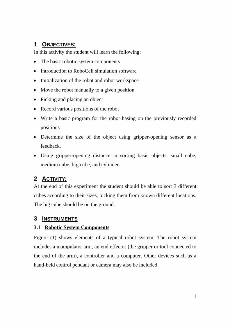
1 OBJECTIVES: In this activity the student will learn the following:
• The basic robotic system components
• Introduction to RoboCell simulation software
• Initialization of the robot and robot workspace
• Move the robot manually to a given position
• Picking and placing an object
• Record various positions of the robot
• Write a basic program for the robot basing on the previously recorded
positions
• Determine the size of the object using gripper-opening sensor as a
feedback.
• Using gripper-opening distance in sorting basic objects: small cube,
medium cube, big cube, and cylinder.
2 ACTIVITY: At the end of this experiment the student should be able to sort 3 different
cubes according to their sizes, picking them from known different locations.
The big cube should be on the ground.
3 INSTRUMENTS 3.1 Robotic System Components
Figure (1) shows elements of a typical robot system. The robot system
includes a manipulator arm, an end effector (the gripper or tool connected to
the end of the arm), a controller and a computer. Other devices such as a
hand-held control pendant or camera may also be included.

2
Figure (1). Elements of typical robotic system.
Some robot systems contain internal feedback devices (such as encoders),
and may include external sensing devices (such as a vision system).
3.1.1 End Effector A robot must be properly equipped for the kind of task it is to perform. The
end effector of the ER 4u is a gripper that can be used for grasping and
picking up objects. In other robotic systems the end effector may be a tool,
such as a welding gun, a spray gun for painting, or a grinding tool for
milling.
3.1.2 Manipulator (arm) A manipulator is a mechanical arm that moves (manipulates) the end
effector to the required positions and orientation. The manipulator arm must
3
be strong enough to carry the specified payload and flexible enough to
perform the required movements with the required level of accuracy.
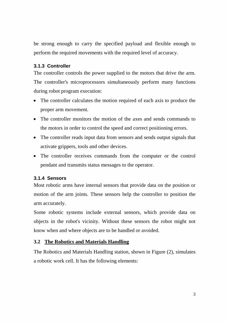
3.1.3 Controller The controller controls the power supplied to the motors that drive the arm.
The controller's microprocessors simultaneously perform many functions
during robot program execution:
• The controller calculates the motion required of each axis to produce the
proper arm movement.
• The controller monitors the motion of the axes and sends commands to
the motors in order to control the speed and correct positioning errors.
• The controller reads input data from sensors and sends output signals that
activate grippers, tools and other devices.
• The controller receives commands from the computer or the control
pendant and transmits status messages to the operator.
3.1.4 Sensors Most robotic arms have internal sensors that provide data on the position or
motion of the arm joints. These sensors help the controller to position the
arm accurately.
Some robotic systems include external sensors, which provide data on
objects in the robot's vicinity. Without these sensors the robot might not
know when and where objects are to be handled or avoided.
3.2 The Robotics and Materials Handling
The Robotics and Materials Handling station, shown in Figure (2), simulates
a robotic work cell. It has the following elements:

4
Figure (2). Robotic Work cell.
• SCORBOT-ER 4u robot and controller. The SCORBOT robot is an
instructional robot, which provides an inexpensive yet reliable simulation
of industrial robots.
• Computer with SCORBASE or RoboCell software.
• Experiment (I/O) table. This item contains microswitches that send input
signals to the controller, a lamp and a buzzer that respond to the
controller output signals. You will use it to simulate the input and output
signals that provide communication among the devices and machines in
the robot's environment.
• Conveyor belt. This device serves to demonstrate the delivery of
materials to and from the robot. It includes a photoelectric sensor whose
5
signal indicates to the robot controller that a part is in the vicinity of the
sensor.
• The robotic cell is supplied with a number of cylindrical and cubical
blocks, referred to as round and square blocks in this manual, which
represent materials and work pieces that the robot handles.
• A coordinate grid. A metal or plastic mat marked with a grid to help you
in learning to manipulate and program the robot.
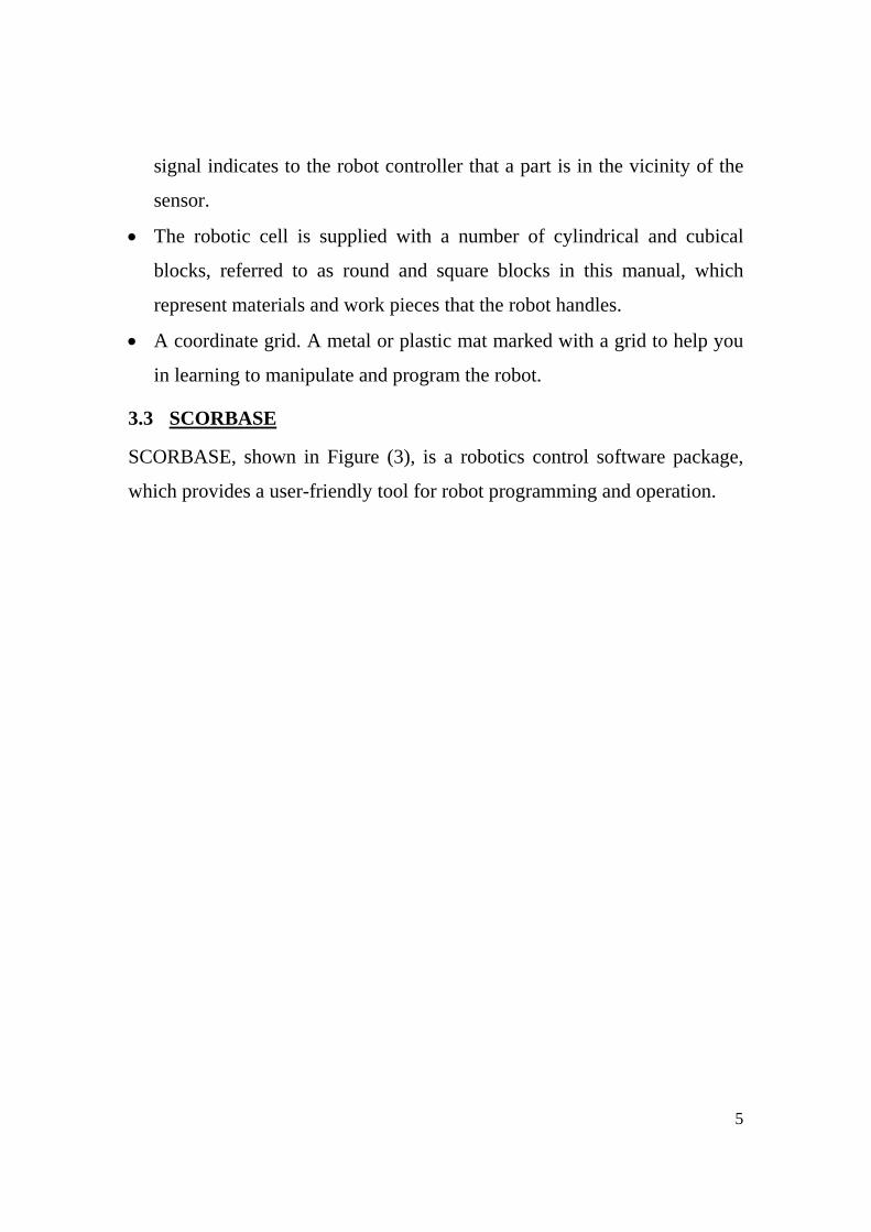
3.3 SCORBASE
SCORBASE, shown in Figure (3), is a robotics control software package,
which provides a user-friendly tool for robot programming and operation.
6
Figure (3). SCORBASE and RoboCell robotic software main window.
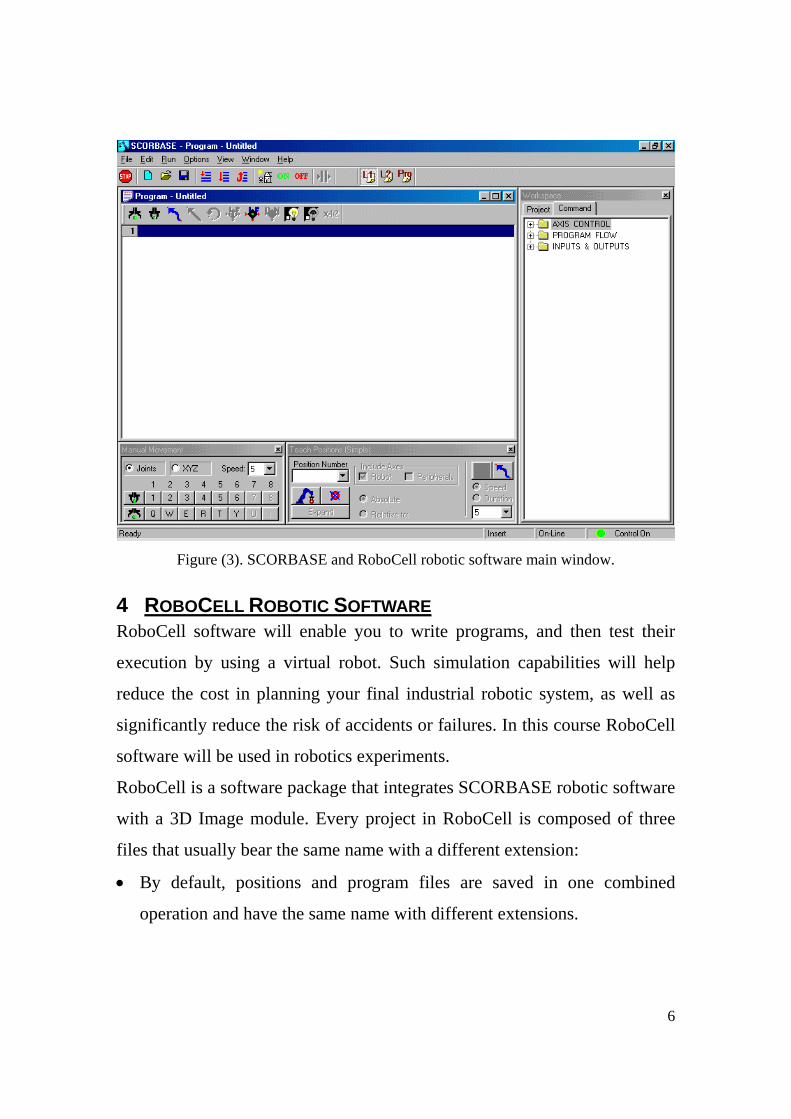
4 ROBOCELL ROBOTIC SOFTWARE RoboCell software will enable you to write programs, and then test their
execution by using a virtual robot. Such simulation capabilities will help
reduce the cost in planning your final industrial robotic system, as well as
significantly reduce the risk of accidents or failures. In this course RoboCell
software will be used in robotics experiments.
RoboCell is a software package that integrates SCORBASE robotic software
with a 3D Image module. Every project in RoboCell is composed of three
files that usually bear the same name with a different extension:
• By default, positions and program files are saved in one combined
operation and have the same name with different extensions.
7
• A file, with the 3DC extension, containing the data regarding the robot
cell. After loading a 3D model file, the 3D Image window shows a
graphic image of the cell.
When the SCORBASE program is executed, the virtual robot will move
within the defined workcell, according to the program positions and
commands.
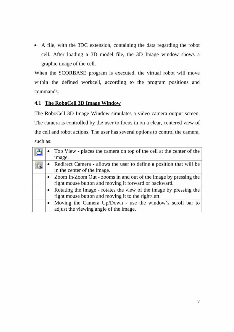
4.1 The RoboCell 3D Image Window
The RoboCell 3D Image Window simulates a video camera output screen.
The camera is controlled by the user to focus in on a clear, centered view of
the cell and robot actions. The user has several options to control the camera,
such as:
• Top View - places the camera on top of the cell at the center of the
image.
• Redirect Camera - allows the user to define a position that will be in the center of the image.
• Zoom In/Zoom Out - zooms in and out of the image by pressing the right mouse button and moving it forward or backward.
• Rotating the Image - rotates the view of the image by pressing the right mouse button and moving it to the right/left.
• Moving the Camera Up/Down - use the window’s scroll bar to adjust the viewing angle of the image.
8
Figure (4). RoboCell 3D Image Window
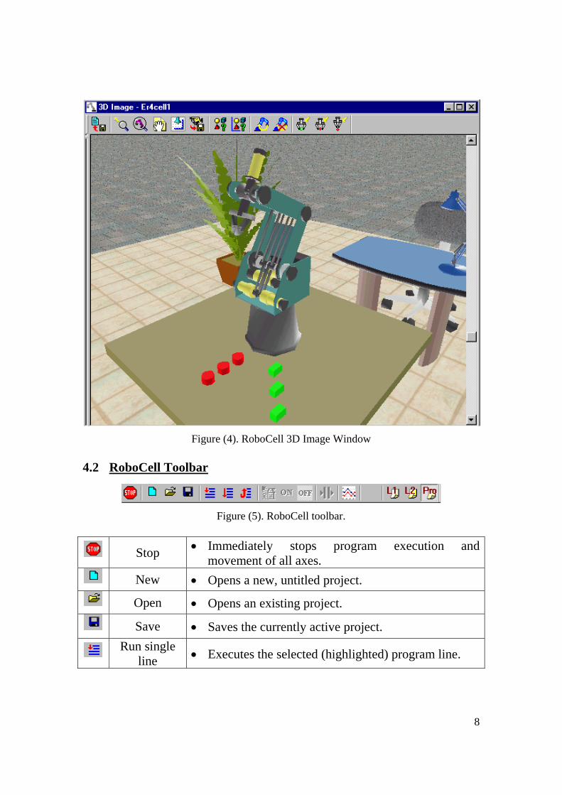
4.2 RoboCell Toolbar
Figure (5). RoboCell toolbar.
Stop • Immediately stops program execution and movement of all axes.
New • Opens a new, untitled project.
Open • Opens an existing project.
Save • Saves the currently active project.
Run single line • Executes the selected (highlighted) program line.

9
Run single circle
• Executes the program from the selected (highlighted) program line, to the end of the program.
Run continuously
• Executes the program from the selected (highlighted) program line. When the last program line is reached, the program starts again from the first line.
Search Home • Search Home for all axes
Control On • Enables servo control of the axes.
Control Off • Disables servo control of the axes. When control is off, axes cannot be moved.
Pause • Stops program execution after the current line is executed.
Charts • Opens the Charts window.
Level 1 • Displays list of commands and options at
introductory level. Commands related to higher level are disabled.
Level 2 • Displays list of commands and options at advanced
level. Commands related to higher level are disabled.
Pro • Displays list of commands and options at
professional level. At this level, all options and commands can be activated.
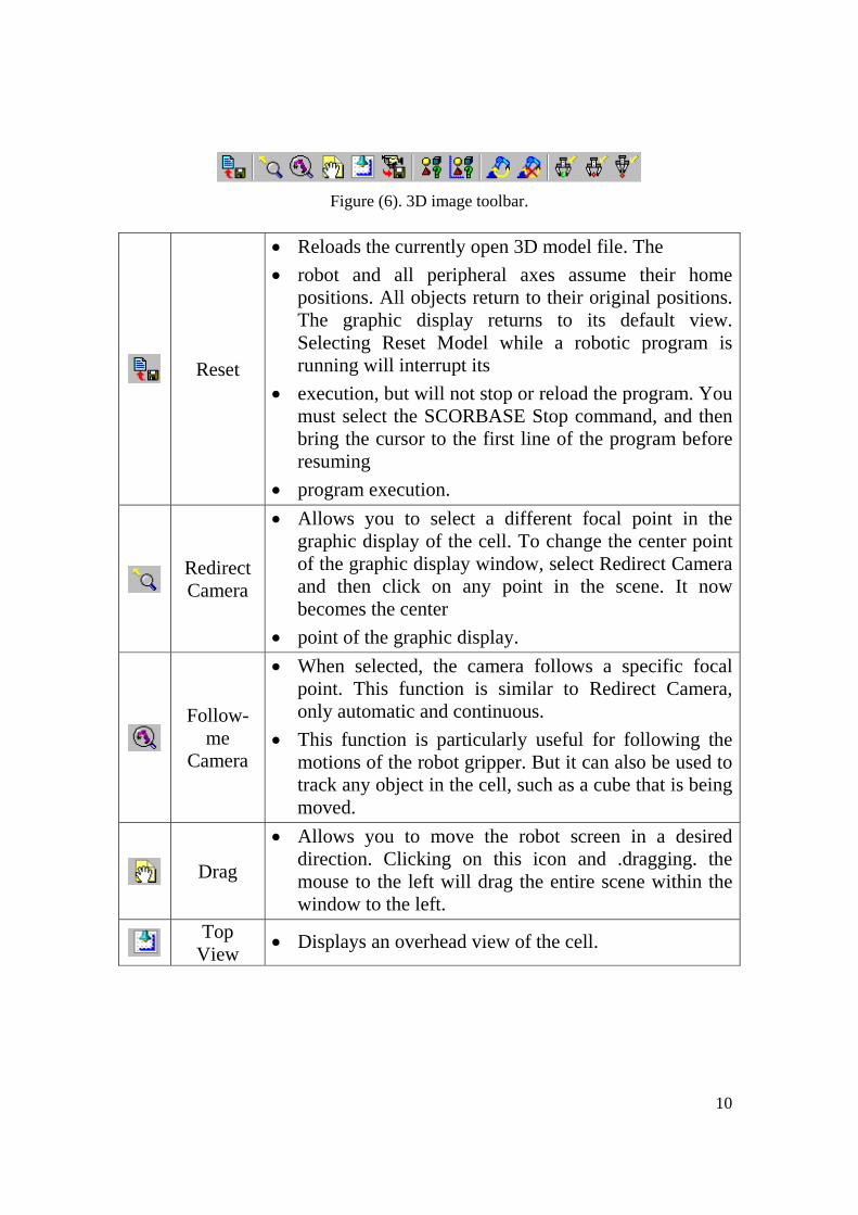
4.3 3D Image Toolbar
10
Figure (6). 3D image toolbar.
Reset
• Reloads the currently open 3D model file. The • robot and all peripheral axes assume their home
positions. All objects return to their original positions. The graphic display returns to its default view. Selecting Reset Model while a robotic program is running will interrupt its
• execution, but will not stop or reload the program. You must select the SCORBASE Stop command, and then bring the cursor to the first line of the program before resuming
• program execution.
Redirect Camera
• Allows you to select a different focal point in the graphic display of the cell. To change the center point of the graphic display window, select Redirect Camera and then click on any point in the scene. It now becomes the center
• point of the graphic display.
Follow-
me Camera
• When selected, the camera follows a specific focal point. This function is similar to Redirect Camera, only automatic and continuous.
• This function is particularly useful for following the motions of the robot gripper. But it can also be used to track any object in the cell, such as a cube that is being moved.
Drag
• Allows you to move the robot screen in a desired direction. Clicking on this icon and .dragging. the mouse to the left will drag the entire scene within the window to the left.
Top
View • Displays an overhead view of the cell.
11
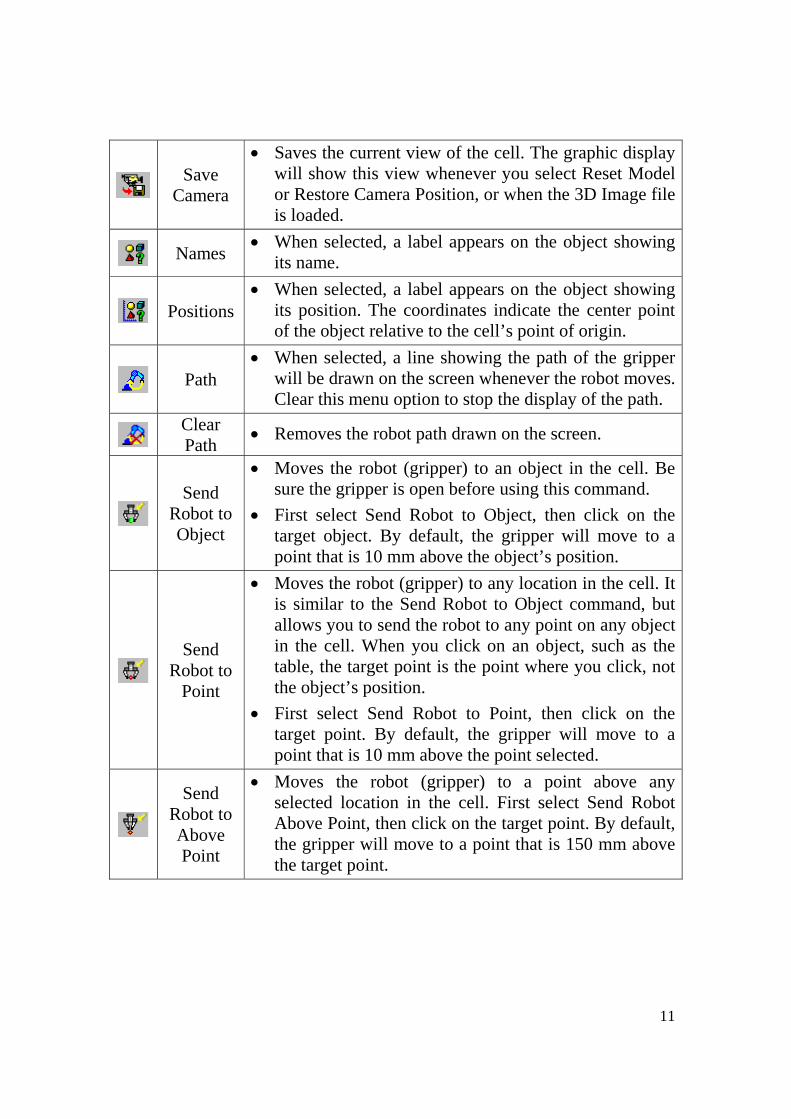
Save
Camera
• Saves the current view of the cell. The graphic display will show this view whenever you select Reset Model or Restore Camera Position, or when the 3D Image file is loaded.
Names • When selected, a label appears on the object showing its name.
Positions • When selected, a label appears on the object showing
its position. The coordinates indicate the center point of the object relative to the cell’s point of origin.
Path • When selected, a line showing the path of the gripper
will be drawn on the screen whenever the robot moves. Clear this menu option to stop the display of the path.
Clear Path • Removes the robot path drawn on the screen.
Send
Robot to Object
• Moves the robot (gripper) to an object in the cell. Be sure the gripper is open before using this command.
• First select Send Robot to Object, then click on the target object. By default, the gripper will move to a point that is 10 mm above the object’s position.
Send
Robot to Point
• Moves the robot (gripper) to any location in the cell. It is similar to the Send Robot to Object command, but allows you to send the robot to any point on any object in the cell. When you click on an object, such as the table, the target point is the point where you click, not the object’s position.
• First select Send Robot to Point, then click on the target point. By default, the gripper will move to a point that is 10 mm above the point selected.
Send Robot to Above Point
• Moves the robot (gripper) to a point above any selected location in the cell. First select Send Robot Above Point, then click on the target point. By default, the gripper will move to a point that is 150 mm above the target point.

12
5 EXPERIMENTAL PROCEDURE: 5.1 Running RoboCell and Opening the Demo 3D model File
1. Turn on the computer.
2. Run RoboCell by doing one of the following:
• Click Start | Programs | RoboCell for ER 4u | RoboCell for ER 4u.
• Click on the RoboCell for ER 4u icon.
The opening screen appears.
Figure (7). RoboCell for ER 4u program window.
3. Every SCORBASE program is part of a project, which can also include
the user-defined positions, project data and 3D model files. In order to
write your first SCORBASE program, you must open a new project.
To open a new project, do one of the following:

13
• Select File | New Project.
• Click on the New Project icon.
• Press [Ctrl] + N.
The RoboCell screen now appears as shown Figure (8).
Figure (8). RoboCell window after opening a new project.
4. You now need to open a 3D image model for this project.
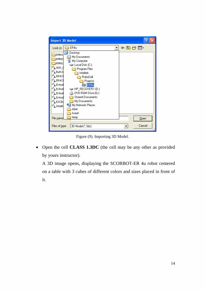
• Select File | Import 3D Model.
The Import 3D Model dialog box opens.
• Go to the directory
C:\Program Files\Intelitek\RoboCell\Projects\ER4u as shown in
Figure (9)
14
Figure (9). Importing 3D Model.
• Open the cell CLASS 1.3DC (the cell may be any other as provided
by yours instructor).
A 3D image opens, displaying the SCORBOT-ER 4u robot centered
on a table with 3 cubes of different colors and sizes placed in front of
it.
15
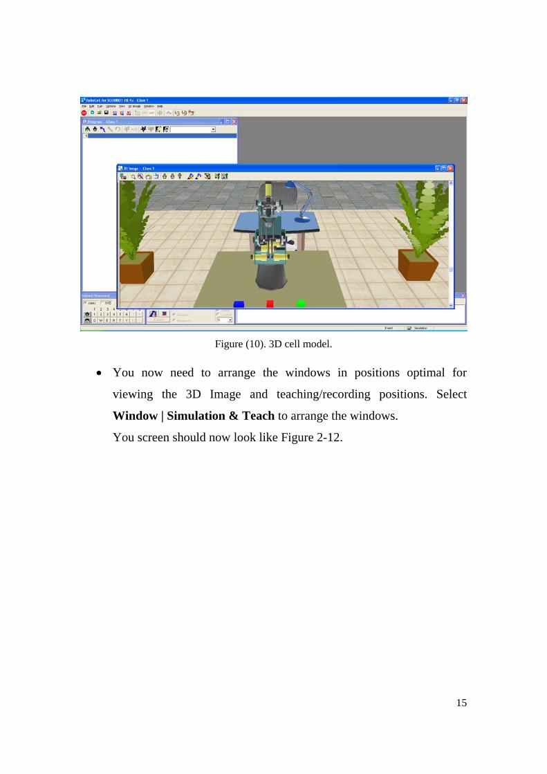
Figure (10). 3D cell model.
• You now need to arrange the windows in positions optimal for
viewing the 3D Image and teaching/recording positions. Select
Window | Simulation & Teach to arrange the windows.
You screen should now look like Figure 2-12.

16
Figure (11). 3D cell model after rearranging program windows.
5.2 Recording Positions
1. Move the robot to the positions shown in Figure (12) and record them.

17
Figure (12). 3D cell model after rearranging program windows.
Note that positions (3, 6, & 9) are just above the cubes. You can record
them relative to positions (4, 5, & 10) 40 mm above as follows:
2. Move the robot to position 4 and record it. Be aware of the orientation of
the gripper.
3. Change programming level to level 2 . You should be able to click
Expand on Teach Positions window.
4. Click it, new items appear.
4710
258
1
369

18
5. Now you can record position 5 relative to position 4, which will be 40
mm above it (in the z-direction).
6. After filling all the previous values, click on Teach.
Note that if you click on Get Position you will obtain the position of
each point and you will know whether this position is absolute or
relative.
7. Repeat the previous steps for all the other positions. Record positions (2,
5, & 8) relative (3, 6, & 9) 50 mm above.
5.3 Size of gripper as a variable in the program
1. Make the following simple program

19
2. Change the level to Professional to be able to use new commands from
Workspace | Commands window
3. In the Workspace | Commands window go to AXIS CONTROL |
SetVariableToGripperSensor… and double click on it.
The following window opens:
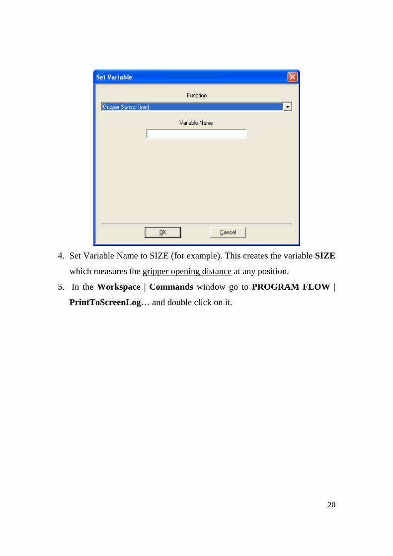
20
4. Set Variable Name to SIZE (for example). This creates the variable SIZE
which measures the gripper opening distance at any position.
5. In the Workspace | Commands window go to PROGRAM FLOW |
PrintToScreenLog… and double click on it.

21
The following window appears:
6. In the Text field place 'SIZE' (variable name).
7. The resulted program should have the following form:
Variable name must be entered between ‘’
Output is displayed on the output window only

22
8. If we run the program from the first line a new window appears
displaying the output:
9. If, for some reasons, this window does not appear, it can be opened from
View | Messages menu.
As can be seen, the size of the cube is displayed and equals 50 mm.
5.4 Programming an if statement basing on size of gripper-opening
The if statement can be found in Workspace | Commands window |
PROGRAM FLOW | IfJump…

23
It can be used in the program as follows:
1. Double-click on IfJump command. The following window appears:
2. At any instant the user can end the program using End command from
the same Command window group.

24
3. Also the label can be placed at any position of the program using the
Label command in the previous figure. If double clicked the following
window appears:
4. After some modifications the resulted program is shown in the next
figure:
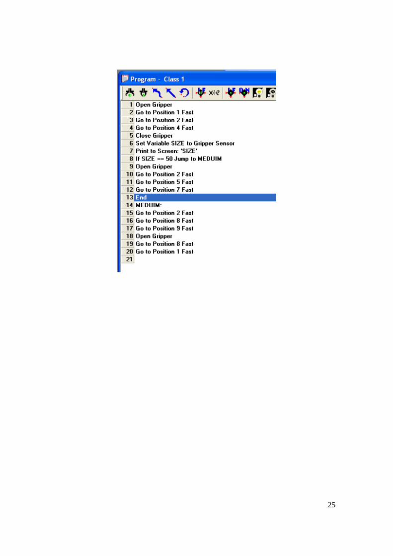
25