Activated carbon and its application
26
Activated Carbon and its Application for Monitoring o£ Volatile Organic Compounds : A Case Study Dr. S.P. Singh Scientist Central Fuel Research Institute Nagpur Unit, Nagpur and Ms. Sarika N. Deole National Environmental Engineering Research Institute, Nagpur Introduction Due to rapid development and industrialization in many countries, the levels of industrial pollution to the atmosphere have been steadily rising. One of these problems is the emission of toxic gases, which can have catastrophic effects on the environment and the general populace. Examples of some of these sources of toxic gas pollutants are volatile organic compounds emission from crystallized organic chemicals, printed materials, paints and coatings and dry cleaning fluids. The availability of variety of Granular Activated Carbon (GAC) samples in several countries, its versatility as an adsorbent and the recent inroads into the regeneration of spent GAC samples for many cycles (Skinner et. al.) have further boosted its application in air pollution monitoring and control. Preparation of activated carbon The principle of manufacturing carbonaceous adsorbents is the selective removal of some groups of compounds from the suitable carbon containing materials such as wood, peat, lignite (Allen et. al.), bituminous coal, coconut shell, walnut shell, coke fines etc (Merchant et. al.). These raw materials are first subjected to carbonisation, which is usually carried out in the absence of air at 19 6. A
-
Upload
ecrd2015 -
Category
Environment
-
view
241 -
download
4
Transcript of Activated carbon and its application

Activated Carbon and its Application for Monitoring o£ Volatile Organic Compounds :
A Case Study Dr. S.P. Singh
Scientist Central Fuel Research Institute Nagpur Unit, Nagpur
and
Ms. Sarika N. Deole National Environmental Engineering Research Institute, Nagpur
Introduction
Due to rapid development and industrialization in many countries, the
levels of industrial pollution to the atmosphere have been steadily rising. One of
these problems is the emission of toxic gases, which can have catastrophic
effects on the environment and the general populace. Examples of some of these
sources of toxic gas pollutants are volatile organic compounds emission from
crystallized organic chemicals, printed materials, paints and coatings and dry
cleaning fluids. The availability of variety of Granular Activated Carbon (GAC)
samples in several countries, its versatility as an adsorbent and the recent
inroads into the regeneration of spent GAC samples for many cycles (Skinner et.
al.) have further boosted its application in air pollution monitoring and control.
Preparation of activated carbon
The principle of manufacturing carbonaceous adsorbents is the selective
removal of some groups of compounds from the suitable carbon containing
materials such as wood, peat, lignite (Allen et. al.), bituminous coal, coconut
shell, walnut shell, coke fines etc (Merchant et. al.). These raw materials are first
subjected to carbonisation, which is usually carried out in the absence of air at
19 6. A

600 - 900 °C. However, this is not a universal temperature range. After
carbonisation the product is subjected to physical or chemical activation.
In physical activation the raw material is first carbonised at high
temperature in a high temperature carbonisation unit and later the carbonised or
coked material is subjected to the action of an oxidising agent such as steam or
carbon dioxide or the mixture of two. At activation temperature between 800-
1000 °C, part of the carbon gets gasified according to the following reactions
(Faust et. al.):
H 2 0 + Cx > H + CO + C ( x- i) (at 800 to 900 °C) — (1)
C0 2 + Cx > 2 CO + C(X_i) (at 800 to 900 °C) — (2)
0 2 + Cx > C0 2 + C(x - 2 ) (at 800 to 900 °C) — (3)
The oxidation step selectively erodes the surface, increasing the surface
area and porosity leaving the carbon surface full of surface groups having
specific affinities and a highly porous carbon skeleton with numerous capillaries,
which provide an immense internal surface area (Hashimoto et. al.).
In the chemical activation process, the source material is mixed with
dehydrating or oxidising agents like zinc chloride, phosphoric acid, sulphuric acid
or KOH (Naidu et. al., Toshiro Otowa et. al. and Lane Jorge) . The mixture is
then subjected to activation at temperatures between 400 and 950 °C. In the final
step, chemicals used for activation are reclaimed by washing the final product.
Chemically activated carbons feature an open pore structure, which makes them
particularly suitable for the adsorption of large molecules. Steam activated
carbon typically exhibits a narrow pore structure and is preferably used for air
purification and adsorbing low molecular substances. The manufacture of high
quality activated carbon with defined and uniform characteristics requires a
sound knowledge and years of experience.
19 6. A

There are many existing companies all over the world, which are
producing a wide range of activated carbons for a variety of gas phase and liquid
phase applications such as gas separation, gas purification, solvent recovery,
colour and odour removal and purification. Some of the internationally known
producers of PAC and GAC are Pittsburgh Activated Carbon, Union Carbide and
Westvaco (U.S.A) , Sutcliff and Speakmann, Bergwerkseverband GmbH
(Jungeten et. al.), LURGI & Degussa (Germany) and Norit Activated Carbon
(Neatherland). The raw material used by most of these producers is bituminous
and anthracite coals. The general steps involved in the GAC or PAC production
are:
Preparation of Activated carbon.
In India, Indian Institute of Chemical Technology, Hydrabad, has
developed granular activated carbon from coconut shells. The product granules
were irregular in shape with N2-BET surface area of 900 m2/g and particle
density of 0.802 g/cm3. Central Fuel Research Institute, Dhanbad (Choudhury et.
al.) too has produced granular and powdered activated carbons from various raw
materials such as coal (Samla), South Arcot lignite (SAL), Kutch lignite, Rajpasdi
lignite, pine wood, soft wood saw dust, coconut shells, walnut shells, groundnut
shells at laboratory and pilot plant scale by both physical and chemical activation
methods. Granular or palletised active carbons prepared from raw materials like
19 6. A

coconut shells, saw dust and rice husk were found to be suitable for gas phase
adsorption whereas those prepared from South Arcot lignite , Kutch lignite , non
caking Samla coal, soft wood, and certain other shells showed good
decolourising properties. These carbons had comparatively lower surface area
than the commercially available carbons but their decolourising power was
comparable. Naidu et.al. at National Environmental Engineering Research
Institute, Nagpur, obtained activated carbon from coke fine having N2-BET
surface area of 526 m2/g and bulk density of 0.660 g/cm . It showed a good
decolourising power but required much higher contact time for maximum removal
of organic carbon from wastewater. Srivastava and co-workers prepared cheap
carbonaceous adsorbent material from fertiliser waste and the product was found
to have a very good adsorption potential form substituted phenols.
Characterization of Activated carbon
Molecular and crystalline structure of activated carbon
An understanding of the molecular and crystalline structure of activated
carbon is necessary to discuss the surface chemistry of this material. The only
apparent difference between activated carbon and carbon black is the small
surface area of the latter. The basic structural unit of activated carbon and
carbon black is closely approximated by the structure of pure graphite (Walker et.
al.). The graphite crystal structure is composed of layers of fused hexagons held
approximately 3.35 A0 apart. The carbon-carbon bond distance with each layer is
1.415 A0. Three out of four electrons form regular covalent bonds with adjacent
atoms, and the fourth electron resonates between several valence bond
structures. This gives each carbon-carbon bond a one third double bond
character. The carbon layers are so arranged that one half of the carbon atoms
in any plane lie above the centre of the hexagons in the layer immediately below
it. X-ray diffraction data indicates that this structure predominates for graphite
(Heckman et. al.). During the carbonisation, several aromatic nuclei having a
19 6. A

structure similar to graphite are formed. The X-ray spectrographs interpreted
these structures as micro crystallites consisting of fused hexagonal rings of
carbon atoms (Wolff W. F.). The diameter of the planes making up the micro
crystallite is estimated to be 150 A0 and the distance between micro crystallites
ranges from 20-50 °A (Garten et. al.).
Porous structure and surface area
The structure of granular activated carbon is highly heterogeneous and
porous. The pores are widely dispersed and are classified in three categories,
micro, meso and macro pores. In micro pores the effective pore width is less than
2 nm, but the interaction potential is significantly higher than the wider pores
owing to the proximity to the walls and the amount adsorbed at a given relative
pressure is correspondingly enhanced. Micro pores are of greatest significance
for adsorption due to their very large pore volume and about 97% contribution to
the total GAC surface area (Yenkie et. al. and Smisek et. al.).
Chemical Structure
The chemical composition of activated carbon also affects its adsorptive
properties significantly. Activated carbon contains chemically bonded elements
such as oxygen and hydrogen. The hydrogen not only forms part of the oxygen
functional groups but also directly combines with carbon atoms. Hydrogen is
more chemisorbed than oxygen and hence is very difficult to be removed from
the surface of the carbon.
Surface Chemistry
The Fourier-Transform Infrared infrared spectrophotometric analysis
shows the presence of many functional groups on the surface of activated
carbon. They are carboxyl groups, phenolic hydroxyl groups, quinone type
carbonyl groups, normal lactones, fluorescien type lactones, cyclic peroxides,
19 6. A

carboxylic acid, anhydrides etc. Observations of (Mattson et. a!.) the internal
reflectance spectroscopic examination of activated sugar carbons, suggested the
presence of a pair of adjacent carboxylic acid groups. But according to Gorten
and Weiss, no acidic group of such strength as a carboxylic group is present on
the surface of activated carbon. They proposed the presence of lactones of the
fluorescien type to explain the reaction of diazomethane to form hydrolyzable
esters.
Preservation of Carbon
The preservation of carbon after the activation process is another
significant aspect. Activated carbon containing carboxyl type groups, kept in an
oxygen atmosphere will bring about an ageing process. Atmospheric oxygen
reacts with the carbon surface to form primarily carboxyl or lactone groups.
Hence storage of activated carbon at room temperature in an oxygen
atmosphere results in the degradation of the adsorption capacity for a large
number of organic compounds (Coughlin et. al.). In addition to the effect of
storing carbon under normal atmospheric conditions, it must be recognised that
carbon exposed to any oxidising solution generally results in the formation of
oxygen complexes that thermally decompose as carbon dioxide. This means that
activated carbon in contact with chlorine water will revert to a surface chemistry
containing excessive carbonyl and lactone-type groups. As discussed above, this
carbon would have a reduced capacity for adsorbing most organics found in
water.
Monitoring of Volatile Organic Compounds (VOCs) using
activated carbon
Air sample at a flow rate of 200 ml/min is passed through a glass tube
packed with activated charcoal. The organic vapours were absorbed onto the
charcoal. The collected vapours are desorbed using carbon disulfide (CS2) and
19 6. A

SEM of F-300 Grade Activated Carbon
183.1

9
Jf
-j
Concept of sorption in Idealised Activated Carbon Pore Structure
Jf
19 6. A
mncropor*
Space ,1 ccotstblv to both MHorb.nu ,mct Solvent
Spjcv ,iei;«',s&i()/t' 10 solve/it ami smaller •idsoibntv miili'ciilos
Spaca ' accessible only
lo the solvent

oo u>
RSIC,NAGPUR SAMPLE CODE - F300 Thu Sep 26 16!l7:29 1996 Number of (ample scans: 32 Number of background scans: 32 Resolution: 4.000 Sample gain: 1.0 Mirror velocity: 0.6329 Aperture: 69.08 Detector: DTGS KBr Beamsplitter! KBr Source: IR
88
87
4000 3500 3000 2500 2000
Wavenumbers (cm-1) 1500 1000
FT1R Sncctrn of C.AC. Filtrasorb 300
iMJ 3 JUW J JJJJJJJ1

analysed with a gas chromatograph equipped with flame ionization detector for
Benzene, Toluene and Xylene (m,p,o). Activated charcoal with particle size of
0.35 - 0.85 mm is used for packing the absorption tube. However, before
packing the tubes, the charcoal is heated in an inert atmosphere e.g. high purity
N2 at 600°C for 1 hr. To prevent recontamination of the charcoal, it is kept in a
clean atmosphere during its cooling to room temperature, storage & loading into
the tubes. Analytical grade reagents are used for the analysis. Standard solutions
of VOCs of interest are required as reagents for calibration purposes. Carbon
disulphide of chromatograph quality is used as desorption or elution solvent. It is
free from the compounds that may co-elute with the substances of interest.
Carbon disulphide is normally recommended for activated carbon.
The Organic Vapour Sampler
The Organic Vapour Sampler model Envirotech APM 850 used for collecting the samples is described below.
Sampling Assembly:
Activated charcoal tube
The charcoal tube is made of a glass with both ends flame sealed, 70 mm
long with an outside diameter of 6 mm & an inside diameter of 4 mm containing
two sections of 0.35 mm to 0.85 mm of activated charcoal. The adsorbing
section contains 100 mg of charcoal & the back up section 50-mg, specially
designed for large loading capacity of Volatile Organic Compounds. Provided two
sections separated by intent glass tape plugs. Glass beads are packed before
front section of the tube for proper distribution of air, entering into the tube.
This tube has one inlet and two outlets. While sampling inlet is attached to
filter adopter and outlet is connected to suction pump through orifice controlled
Teflon nozzle while other outlet connected to 'u' tube manometer through
184

provided nozzles for pressure measurement. All connections of the tube are
done with the help of silicon tubes. Two sections provided in this tube can be
separated out by removing springs for desorption/extraction of adsorbed organic
compounds separately. Ground glass joints male and female type have been
provided to facilitate assembling and dissembling of the tube.
Rubber caps need to be used for sealing all three opening of the tubes
after sampling and regeneration.
The pressure drop across the tube shall not exceed 3 Kpa (25 mm Hg) at
the flow rate of 200 ml/min recommended for sampling.
Extraction Assembly :-
The extraction assembly consists of the following parts:
Desorption Bulb :
A round bottom glass flask of 25-ml capacity provided with ground glass
connector suitable to fit into both sections of the charcoal tube.
Sample vial & funnel :
While agitating charcoal with elutant in desorption bulb fine carbon
particles are observed in liquid phase. These need to be removed by filtration.
Funnel loaded with filter is attached too sample vial. A 25mm diameter Whatman
glass fibre filter with funnel should be used for filteration of extracted elutant.
Syringes :
Syringe of capacity 10pl & 50pl graduated in 0.1 pi
19 6. A

Sample Analysis
In general a gas liquid chromatograph (GLC) fitted with a flame ionization,
photoionization, mass spectrometric or other suitable detector; capable of
detecting the organic compound in an injection of 0.5 ng of sample with a signal
to noise ratio of at least 5 to 1 can be used. In this study, Perkin Elmer
Autosystem XL gas chromatograph equipped with Flame Ionization Detector
(FID) and Nitrogen as a carrier gas has been used for determination of Benzene,
Toluene & Xylene. The hydrocarbons are determined on 3% Dexsil-300 column.
The column and its operating conditions:
Column
Detector
Carrier Gas
Detector Temp.
Injector Temp.
Isothermal Oven Temp.
S.S. 1/8" O.D., 6" feet
3% Dexsil on 80/100 chromosorb W-AW
FID
Nitrogen 15 ml/min
250 °C
200 °C
55 °C
Operating conditions on suitable column for temperature programming
may vary from 60-120 °C at 4°C/min with a carrier gas flow 10 ml/min to 20
ml/min. Examples of suitable choices with different stationary phases are given in
following Table:
19 6. A

Equivalence of Gas Chromatograph Stationary Phases
Company Equivalence phaseA
Equivalence phaseA
SGE BP-1 BP-10 Chrompack CP-Sil 5 CB BP-10 J & W DB-1 DB-1701 Supelco SPB-1 SPB-1701 Hewlwtt-Packard HP-1 HP-1701 Restek Rtx-1 Rtx-1701 Quadrex 007-1 007-1701
SP-2330 and SP-1000 columns can also be used for the determination of
Volatile Organic Compounds. The suitability of the column shall be verified by
testing with 2 or more columns of dissimilar packing to ensure the absence of
interferences.
Sampling
Connect mains cable in the socket provided on the rear side of the
sampler. Remove rubber caps of Activated Charcoal tube and fit it in the
"hydrocarbon nozzle" with the help of silicon tube. Silicon tube of nozzle marked
as "pressure" is connected to 2nd connection of the tube. Take carbon monoxide
or other gases indicator tube and break glass seal from both end of the tube and
fit it in the nozzle marked with carbon monoxide. Use metallic folding stand for
holding the tubes straight. Take initial reading of the time totalizer. Now switch on
the power supply and see that indicator ON/OFF switch glows. Switch 'ON' the
equipment and check flow in both the tubes with the help of rotameter by
connecting silicon tube of nozzle marked with the flow to the tip of connected
hydrocarbon/ carbon monoxide tube. Record flow reading on the note sheet.
Flow is maintained constant in the equipment with the help of needle type
orifices. Generally flow rate 100 to 200 ml/min is maintained in both the tubes.
Higher flows can also be maintained by choosing different size of needle orifices.
After noting the flow, attach filter adopter loaded with filter on each tube to avoid
entry of particulates in the tubes, which may increase pressure drop and reduce
19 6. A

the adsorption efficiency beyond acceptable limits. Sampling frequency may
vary from 3-8 hrs at traffic junctions/sampling site depending on vehicular
density/peak hours. While operating if no flow is observed check needle fitted in
the Teflon nozzle. It is expected that needle may be chocked, replace needle in
such cases. After operation for desired period check the flow reading and switch
off the suction pump and note the final time totalizer reading. Now take out the
charcoal tube and seal all three openings with the help of supplied plugs after
marking sampling date, time and location on sealed tube. Now this tube needs to
be sent to lab for analysis. Ensure storing of tube at low temperature (sub
ambient temperature) to avoid migration of sorbed compounds from one section
to another. CO tube is removed and concentration of CO is noted by comparing
the colour with provided chart.
Extraction
Open the sealed exposed Activated charcoal tube and separate the
sampling tube's back up section and front section of modular activated charcoal
tube. Extract sampled organic compounds separately from front section &
backup section. Desorption need to be carried out using desorption bulbs. Take
10 ml of AR Grade CS2 or suitable elutant as prescribed in standard analysis
method in desorption bulb. Remove the glass tape from sampling tube and
attach with desorption bulb with the help of provided male-female glass
connector. Extraction is carried out by ultrasonication or it can be carried by
shaking. The desorption bulb containing 10 ml elutant CS2 & exposed activated
charcoal is sonicated for 15 min. Repeat the same procedure for the backup
section using different desorption bulb. Filter extracted solvent if particles are
visible after desorption use 25-mm diameter glass fibre filter & provided funnel
and sample vial. Use only transparent elutant for injecting in the Gas
Chromatograph.
19 6. A

Analysis
The transparent elutant obtained after extraction was used for gas
chromatograph analysis.
A Gas Liquid Chromatograph equipped with Flame Ionization Detector
(FID) and Nitrogen as a carrier gas was kept ready for analysis of VOCs. The
optimized operating conditions were set up as (4>. 3% Dexsil packed column was
used for determination of Benzene, Toluene and Xylene (BTX). Total time
required for complete separation of BTX was about 10 minutes. Retention time in
minutes was measured from the start up of solvent peak. After every sample a
solvent was injected to flush out the column. The choice of column will largely
depend upon compounds and interfering compounds present.
1 pi of Mix standard (BTX = 100 ng/pl) was injected into the Gas
Chromatograph. Replicates of fixed volume of Mix standard was introduced to
get a chromatograph for evaluating precision.
Mix standard was diluted with carbon disulphide (CS2) in 1:1 proportion
and injected under the same GC condition in triplicate to get reproducibility.
In a similar way sample and spiked sample was also injected to get a
repeatable peak pattern.
Results and discussion:
The concentrations of analyte are calculated by measuring peak areas of
respective compounds. Identification of compounds in a sample are done from
the retention time of the standard. Area of Peak is calculated by height times
width at half height.
19 6. A

Area =
h
W =
1/2 x h x W (mm2)
Height of a peak Width of peak at half height
In case of very narrow or sharp peaks only height was considered and
taken as area of a peak.
The concentration of the compounds in desorbed sample in (pg/m3) is
calculated by following formula :
The statistical evaluations of results are shown in Table 1.
The differences observed in Average Mean, Standard Deviation and
% Error in replicate samples show that these errors may be caused by
evaporation losses of standard and sample, varying G.C. conditions and
mannual error during injection. Further studies are going on at the time of
preparing this writeup.
Cone, of Peak height of Volume of Cone, in = standard x sample (mm) x sample (pi) x (ng/m3) (in ng) T e a k height of Volume of
standard (mm) sample injected (pi)
1
Volume of air sampled (m3)
19 6. A

Table 1
GC response for standard solution (100 ng/pl)
Compounds Peak ht. in mm Average Standard Deviation
(+/-) % Error
Benzene 129 129 131 129.6 1.154 0.05
Toluene 95 94 95 94.6 0.577 0.07
Xylene 59 60 60 59.6 0.577 0.11
GC response for Standard + Solvent (1.1)
Compounds Peak ht. in mm Average Standard Deviation
(+/-) % Error
Benzene 62 68 67 65.6 3.214 0.10
Toluene 48 50 51 49.6 1.527 0.13
Xylene 30 32 33 31.6 1.527 0.21
GC response for Sample (2|jl)
Compounds Peak ht. in mm Average Standard Deviation
(+/-) % Error
Benzene 15 16 15 15.3 0.577 0.21
Toluene 5 5 4 4.6 0.577 1.44
Xylene 7 6 7 6.6 0.577 1.01
19 6. A

GC response for Standard + Sample (1.1)
Compounds Peak ht. in mm Average Standard Deviation
(+/-) % Error
Benzene 68 72 75 71.6 3.511 0.09
Toluene 52 55 60 55.6 4.041 0.14
Xylene 36 38 41 38.3 2.516 0.08
GC response for Standard + Sample (pg/m3)
Compounds Peak ht. in mm Average Standard Deviation
(+/-) % Error
Benzene 52.46 52.77 52.08 52.43 0.345 0.023
Toluene 54.96 55.23 57.08 55.75 1.153 0.013
Xylene 60.40 60.57 61.91 60.96 0.827 0.003
19 6. A
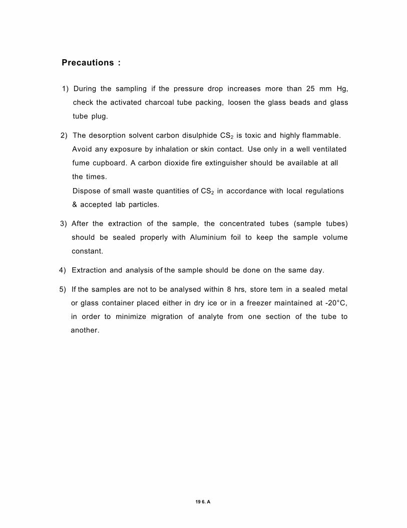
Precautions :
1) During the sampling if the pressure drop increases more than 25 mm Hg,
check the activated charcoal tube packing, loosen the glass beads and glass
tube plug.
2) The desorption solvent carbon disulphide CS2 is toxic and highly flammable.
Avoid any exposure by inhalation or skin contact. Use only in a well ventilated
fume cupboard. A carbon dioxide fire extinguisher should be available at all
the times.
Dispose of small waste quantities of CS2 in accordance with local regulations
& accepted lab particles.
3) After the extraction of the sample, the concentrated tubes (sample tubes)
should be sealed properly with Aluminium foil to keep the sample volume
constant.
4) Extraction and analysis of the sample should be done on the same day.
5) If the samples are not to be analysed within 8 hrs, store tem in a sealed metal
or glass container placed either in dry ice or in a freezer maintained at -20°C,
in order to minimize migration of analyte from one section of the tube to
another.
19 6. A

References :
Skinner, J.H. and Bassin, N.J.; The Environmental Protection Agency's
Hazardous Waste Research and Development Program, J APCA, 38(4), 377-
387 (1988)
Allen, S.J., Balasundaram, V., and Chowdhury, M., "Development and
characterisation of specialty activated carbon from lignite", pp. 35-42, in "The
fundamentals of adsorption - Proceedings of the Vth International Conference
on Fundamentals of Adsorption, Editor: M. Douglas LeVan, Kluwer Academic
Publishers (1996).
Merchant, A.A., and Petrich, M.A., A I Ch E J., 39(8), 1370-1376 (1993)
Faust, S.D. and Aly, O.M.; in "Adsorption processes for water treatment" pp.
168-170, Butterworth Publishers (1987).
Hashimoto Kenji, Miura, Yoshikawa Fumiaki ,and Imai Ichiro;
l&EC Process Design & Development ;18 , 72 (1979).
Naidu P.S., Ramteke D.S., Rao, K.S.M. and Kumaran P, J.;
Research and Industry , 35 ,.237-241 (1990)
Toshiro Otowa, Yutaka, Nojima and M. Itoh in "Activation mechanism, surface
properties and adsorption characterisitcs of KOH activated high surface area
carbon" pp. 709-716, in "The fundamentals of adsorption - Proceedings of the
Vth International Conference on Fundamentals of Adsorption, Editor : M.
Douglas LeVan, Kluwer Academic Publishers (1996).
Lane Jorge , Carbon, 30(4), 601-604(1992).
Juntgen H., Klein Jurgen, Knoblauch K., Schroten Hans-Jurgen, and Schulze
Joachim in Chemistry of Utilization, llnd Supplementary Volume, Chapter -30,
Editor. Elliott Martin A.; 2144-2145 (1981).
19 6. A

Choudhury, S.B., Banerjee, D.K., Dutta A.C., Mazumdar S., Ray A.K. and
Prasad M.;
Fuel Science and Technology, 4, 129-133 (1990).
Srivastava S.K. and Tyagi, Renu ; Fresenius Environ. Bull., 3(1), 12-17
(1994)
Walker, P.L., Jr., "Carbon An Old But New Material", Am. Scientist, 50, 250
(1962)
Heckman, F.A.; Rubber Chem. Technol., 37,1245 (1964)
Wolff, W.F.; J. Phys. Chem., 63, 653 (1959)
Garten, V.A. and Weiss, D.E., Rev. Pure Appl. Chem., 7, p 69, (1957)
Yenkie, M.K.N, and Natarajan, G.S.; Sep. Sci. & Technol. 28(5), 1177-1190
(1993)
Smisek, M. and. Cerny, S. ; Active Carbon ( Elsevier Publishing Company,
Amsterdam 1970)
Mattson, J.S., Mark, H.B. Jr., Malbin, M.D., Weber, W.J. Jr. and Crittenden,
J.C., J. Colloid Interface Sci., 31, 116 (1969)
Coughlin, R.W., Ezra, F.S. and Tan, R.N. ; J Colloid Interface Sci., 28, 386
(1968).
Commuter exposures to VOCs under different driving conditions. Atmo. Env.
Vol.33, Nov 1998, pg. No. (409-417)
Organic emissions profile for a light duty diesel vehicle. Atmo. Env. Vol.33
(Nov 1998) No.5, pg. No. 797
Fast & quantitative measurement of benzene, toluene & C2-benzenes in
automotive exhaust during transient engine operation with & without catalytic
exhaust gas treatment. Atmo. Env. Vol.33 No.2 (Nov 1998) pg. No.205
19 6. A

Handbook of Air Pollution from Internal Combustion Engines.
Pollutant formation & control Edited by Eran Sher. (Academic Press)
Characterisation & control of odours & VOC in the process industries
Edited by S. Vigneron, J.Hermia, J.Chaauki
Historical Accuracy measurement of VOCs in ambient air using compendium
method T014/15 : Reference samples, canister surrogates & Green house
gases. By Michael G.Winslow, D.F. Roberts. From : Book "Measurement of
Toxic & Related Air Pollutants", Sponsored by Air & Waste Management
Association
19 6. A

ORGANIC VAPOUR SAMPLER
Code Details Code Detai Is
© Cabinet © Teflon Nozzel for HC Supply
© Handle © Tef Ion Nozzel for CO Supply
® On/off Switch © Mercury Manometer
© Time Totalizer © Nozzel for pressure measuring
© Flow Measurment Nozze! © Stand
© Outlet Nozzel for collecting sample
© Rotameter -
196.1

NO. Details
1 OutleM, for suction to pump
2 Outlet-2,for pressure drop-to 'U' Manometer
3 Spring
4 Glass Tape-Plug
5 Activated Charcoal
6 Glass Beads
7 Inlet for air attach fi l ter adopter
FIG. 1: ACTIVATED CHARCOAL TUBE
1QC

Details
Activated Charcoal
Glass Beads
Inlet for air attach filter adopter
SAMPLE VIAL
FILTER ADOPTER
Details
Outlet-1, for sucktion-to pump Outlet-2, for pressure drop-to 'U' Manomete Spring Glass Tape - Plug
ACTIVATED CHARCOAL TUBE

FlG,2(g):CHR0MAT0GRAM FOR MIX STANDARD FlG.2 (b): C HROMATOGR AM FOR MIX STANDARD-*- SOLVENT(1-1)
FIG. 2 :CHRQMATQGRAM OF VQCs
VQCs :-1. BENZENE 2. T O L U E N E 3. p -XYLENE A. tn-XYLENE 5. o - X Y L E N E
F1G.2: (C):CHR0MAT0GRAM FOR AIR SAMPLE FIG.2 ( d) '• C H ROM ATOGRA M FOR STANDARD* SAM PL E( 1:1)
19 6. A