Activated Carbon Composites for Air Separation · Activated Carbon Composites for Air ... Activated...
28
ORNL/TM-2007/239 Activated Carbon Composites for Air Separation December 2007 Prepared by Cristian I. Contescu Senior Staff Member Oak Ridge National Laboratory
Transcript of Activated Carbon Composites for Air Separation · Activated Carbon Composites for Air ... Activated...
ORNL/TM-2007/239
Activated Carbon Composites for Air Separation
December 2007
Prepared by Cristian I. Contescu Senior Staff Member Oak Ridge National Laboratory
DOCUMENT AVAILABILITY Reports produced after January 1, 1996, are generally available free via the U.S. Department of Energy (DOE) Information Bridge. Web site http://www.osti.gov/bridge Reports produced before January 1, 1996, may be purchased by members of the public from the following source. National Technical Information Service 5285 Port Royal Road Springfield, VA 22161 Telephone 703-605-6000 (1-800-553-6847) TDD 703-487-4639 Fax 703-605-6900 E-mail [email protected] Web site http://www.ntis.gov/support/ordernowabout.htm Reports are available to DOE employees, DOE contractors, Energy Technology Data Exchange (ETDE) representatives, and International Nuclear Information System (INIS) representatives from the following source. Office of Scientific and Technical Information P.O. Box 62 Oak Ridge, TN 37831 Telephone 865-576-8401 Fax 865-576-5728 E-mail [email protected] Web site http://www.osti.gov/contact.html
This report was prepared as an account of work sponsored by an agency of the United States Government. Neither the United States Government nor any agency thereof, nor any of their employees, makes any warranty, express or implied, or assumes any legal liability or responsibility for the accuracy, completeness, or usefulness of any information, apparatus, product, or process disclosed, or represents that its use would not infringe privately owned rights. Reference herein to any specific commercial product, process, or service by trade name, trademark, manufacturer, or otherwise, does not necessarily constitute or imply its endorsement, recommendation, or favoring by the United States Government or any agency thereof. The views and opinions of authors expressed herein do not necessarily state or reflect those of the United States Government or any agency thereof.
ORNL/TM-2007/239
Materials Science and Technology Division
Activated Carbon Composites for Air Separation
Frederick S. Baker Cristian I. Contescu
Costas Tsouris Joanna McFarlane
Date Published: December 2007
Prepared by OAK RIDGE NATIONAL LABORATORY
Oak Ridge, Tennessee 37831-6283 managed by
UT-BATTELLE, LLC for the
U.S. DEPARTMENT OF ENERGY under contract DE-AC05-00OR22725


iii
CONTENTS
Page LIST OF FIGURES ............................................................................................................................... v
LIST OF TABLES ...............................................................................................................................vii
ACRONYMS ........................................................................................................................................ ix
ACKNOWLEDGEMENTS……………………………………………………………………
… .................................................................................................................................................... x
ABSTRACT .......................................................................................................................................... xi
1. INTRODUCTION .......................................................................................................................... 1
2. MATERIALS PREPARATION AND CHARACTERIZATION….......................................... …. 3
2.1 Carbon Fiber Composite Molecular Sieves (CFCMS) …....... ................................................ 3
2.2 Magnetite-loaded CFCMS… ............................................................. ……………………....5
2.3 Zeolite……………………………...................................................... …………………….. 6
2.4 Experimental……..………………………........................................................ …………….6
3. AIR SEPARATION BASED ON MOLECULAR SIEVING EFFECTS……… .......................... ..7
3.1 Carbon Fiber Composite Molecular Sieves (CFCMS)……… ………….................... … ….7
3.2 Zeolite........................................………………………………………………………… …10
4. INFLUENCE OF MAGNETIC FIELDS ON DYNAMIC AIR SEPARATION....................... …11
5 CONCLUSIONS ............................................................................................................................ 12
REFERENCES.................................................................................................................................. 13

v
LIST OF FIGURES
Figure Page 1 SEM images showing the structure of CFCMS material……………………………….......... 1 2 Cumulative pore volume distribution as a function of pore
width……..………………… ............................................................................................. 3 3 Differential distribution of pore volume as a function of pore
width…………................. .................................................................................................. 4 4 Example of breakthrough nitrogen and oxygen mass spectrometer signals measured for
sample TIM-2 after injection of 5 mL air at various temperatures…………………............................................................................................ 7
5 Normalized mass spectrometer signals for N2 (blue) and O2 (red) breaking through a
50 cm column packed with CFCMS TIM-2 material after injection of air at various temperatures. ................................................................................................................. 8
6 Normalized mass spectrometer signals for N2 (blue) and O2 (red) breaking through a 50 cm column packed with CFCMS K2-B material after injection of air at various temperatures.. ................................................................................................................ 9
7 Mass spectrometer signals showing breakthrough of N2 (blue) and O2 (red) on zeolite
13X after injection of 5 mL air at various temperatures ................................................. 10 8 Example of air separation on zeolite 13X at room temperature…………........ .................... 11


vii
LIST OF TABLES Table Page 1 Surface area and porosity of base CFCMS materials selected for testing .................................... 5

ix
ACRONYMS CFCMS Carbon fiber composite molecular sieves ORNL Oak Ridge National Laboratory ESA electrical swing adsorption PSA pressure swing adsorption DFT density functional theory GC gas chromatograph TC thermal conductivity VTI Vacuum Technology Inc. MS mass spectrometer

x
ACKNOWLEDGEMENTS
Research sponsored by Office of Fossil Energy, U.S. Department of Energy, National Energy Technology Laboratory, under the Fossil Energy Advanced Research Materials Program, contract number DE-AC05-00OR22725 with UT-Battelle, LLC.

xi
ABSTRACT In continuation of the development of composite materials for air separation based on molecular sieving properties and magnetic fields effects, several molecular sieve materials were tested in a flow system, and the effects of temperature, flow conditions, and magnetic fields were investigated. New carbon materials adsorbents, with and without pre-loaded super-paramagnetic nanoparticles of Fe3O4 were synthesized; all materials were packed in chromatographic type columns which were placed between the poles of a high intensity, water-cooled, magnet (1.5 Tesla). In order to verify the existence of magnetodesorption effect, separation tests were conducted by injecting controlled volumes of air in a flow of inert gas, while the magnetic field was switched on and off. Gas composition downstream the column was analyzed by gas chromatography and by mass spectrometry. Under the conditions employed, the tests confirmed that N2 – O2 separation occurred at various degrees, depending on material’s intrinsic properties, temperature and flow rate. The effect of magnetic fields, reported previously for static conditions, was not confirmed in the flow system. The best separation was obtained for zeolite 13X at sub-ambient temperatures. Future directions for the project include evaluation of a combined system, comprising carbon and zeolite molecular sieves, and testing the effect of stronger magnetic fields produced by cryogenic magnets.

xii
1
1. INTRODUCTION
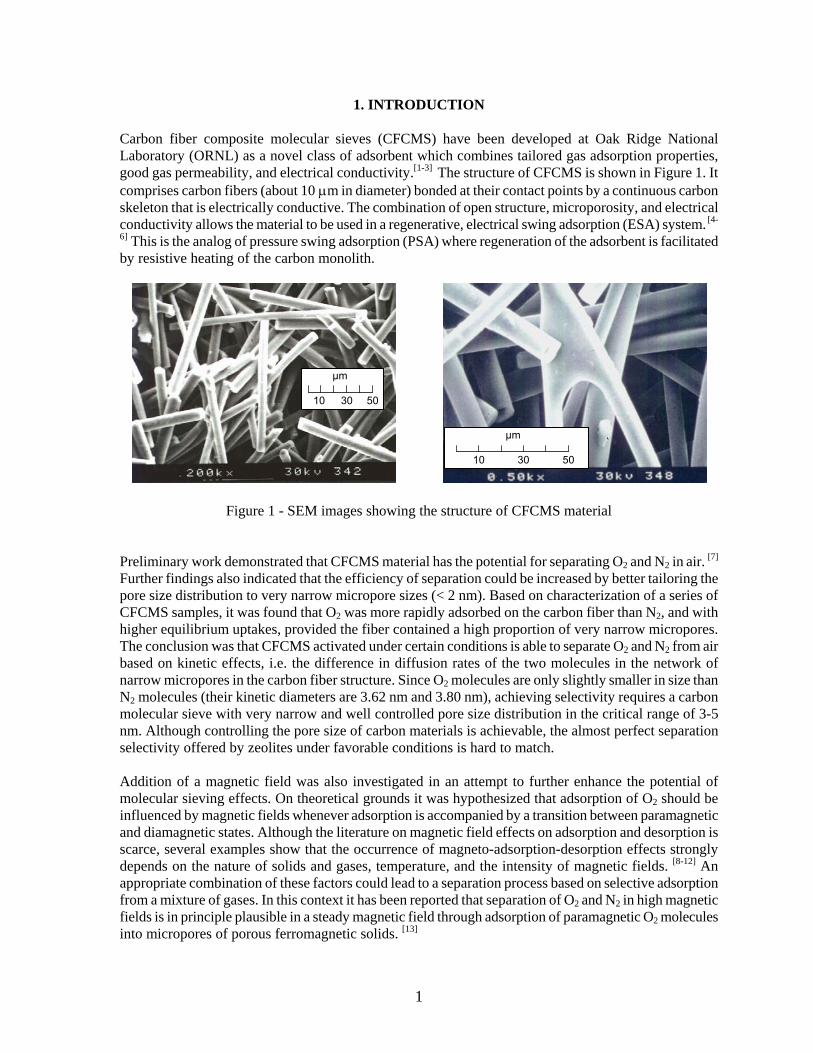
Carbon fiber composite molecular sieves (CFCMS) have been developed at Oak Ridge National Laboratory (ORNL) as a novel class of adsorbent which combines tailored gas adsorption properties, good gas permeability, and electrical conductivity.[1-3] The structure of CFCMS is shown in Figure 1. It comprises carbon fibers (about 10 μm in diameter) bonded at their contact points by a continuous carbon skeleton that is electrically conductive. The combination of open structure, microporosity, and electrical conductivity allows the material to be used in a regenerative, electrical swing adsorption (ESA) system. [4-
6] This is the analog of pressure swing adsorption (PSA) where regeneration of the adsorbent is facilitated by resistive heating of the carbon monolith.
Figure 1 - SEM images showing the structure of CFCMS material Preliminary work demonstrated that CFCMS material has the potential for separating O2 and N2 in air. [7]
Further findings also indicated that the efficiency of separation could be increased by better tailoring the pore size distribution to very narrow micropore sizes (< 2 nm). Based on characterization of a series of CFCMS samples, it was found that O2 was more rapidly adsorbed on the carbon fiber than N2, and with higher equilibrium uptakes, provided the fiber contained a high proportion of very narrow micropores. The conclusion was that CFCMS activated under certain conditions is able to separate O2 and N2 from air based on kinetic effects, i.e. the difference in diffusion rates of the two molecules in the network of narrow micropores in the carbon fiber structure. Since O2 molecules are only slightly smaller in size than N2 molecules (their kinetic diameters are 3.62 nm and 3.80 nm), achieving selectivity requires a carbon molecular sieve with very narrow and well controlled pore size distribution in the critical range of 3-5 nm. Although controlling the pore size of carbon materials is achievable, the almost perfect separation selectivity offered by zeolites under favorable conditions is hard to match. Addition of a magnetic field was also investigated in an attempt to further enhance the potential of molecular sieving effects. On theoretical grounds it was hypothesized that adsorption of O2 should be influenced by magnetic fields whenever adsorption is accompanied by a transition between paramagnetic and diamagnetic states. Although the literature on magnetic field effects on adsorption and desorption is scarce, several examples show that the occurrence of magneto-adsorption-desorption effects strongly depends on the nature of solids and gases, temperature, and the intensity of magnetic fields. [8-12] An appropriate combination of these factors could lead to a separation process based on selective adsorption from a mixture of gases. In this context it has been reported that separation of O2 and N2 in high magnetic fields is in principle plausible in a steady magnetic field through adsorption of paramagnetic O2 molecules into micropores of porous ferromagnetic solids. [13]
10 30 50
μm
10 30 50
μm
2
In order to verify this theoretical prediction, a series of measurements of O2 adsorption isotherms was carried out in static, equilibrium conditions.[14] In preliminary tests it was found that the amount of O2 adsorbed at equilibrium was lower (by about 6% at 0.1 MPa) in presence of a weak magnetic field (0.8 Tesla) than in absence of the magnetic field. Although small, this magnetodesorption effect was sizable and observed repeatedly at room temperature for activated carbon fibers loaded with 10 wt % of super-paramagnetic magnetite nanoparticles (Fe3O4, average size 16 nm). The results of these preliminary tests motivated continuation of the project for additional verification and confirmation of the effect at higher magnetic field intensities and in dynamic conditions; in the new series of tests reported here, a flow system, rather than static, was used to better simulate the conditions of air separation for practical applications. Tests for air separation in absence of a magnetic field were also carried out.

3
2. MATERIALS PREPARATION AND CHARACTERIZATION
2.1 Carbon Fiber Composite Molecular Sieves (CFCMS) A series of CFCMS composites were used as support for loading a dispersed magnetic phase, magnetite. The CFCMS materials were selected based on their microporous structure and BET surface area values.[15] The surface and porosity properties were characterized by adsorption of N2 at 77 K and by adsorption of CO2 at 273 K.[16] All adsorption measurements were made using the Autosorb 1 instrument (Quantachrome). Adsorption data were further processed to calculate the pore size distribution of porosity and surface areas using the density functional theory (DFT) in the non-local density approximation. [16-19] The DFT software available from Quantachrome was used for calculations. Figures 2 and 3 show the results of pore size distribution in form of cumulative and differential plots. The results obtained from N2 adsorption at 77 K (lowest accessible pores ~ 10 Å) and CO2 adsorption at 273 K (pores between 3 and 12 Å) are overlapped in both plots.
0.00
0.10
0.20
0.30
0.40
0.50
0.60
0 5 10 15 20 25 30 35 40 45 50
Pore width (A)
Cum
ulat
ive
pore
vol
ume
(cc/
g)
TIM2 - CO2TIM2 - N2K2-B - CO2K2-B - N2NG-4 - CO2NG-4 - N2
Figure 2: Cumulative pore volume distribution as a function of pore widths. Data calculated by DFT method from N2 adsorption and CO2 adsorption are plotted on a common scale.
4
0.00
0.02
0.04
0.06
0.08
0.10
0.12
1 10 100
Pore width (A)
Diff
eren
tial p
ore
volu
me
(cc/
g/A
)
TIM2 - CO2TIM2 - N2K2-B - CO2K2-B - N2NG-4 - CO2NG-4 - N2
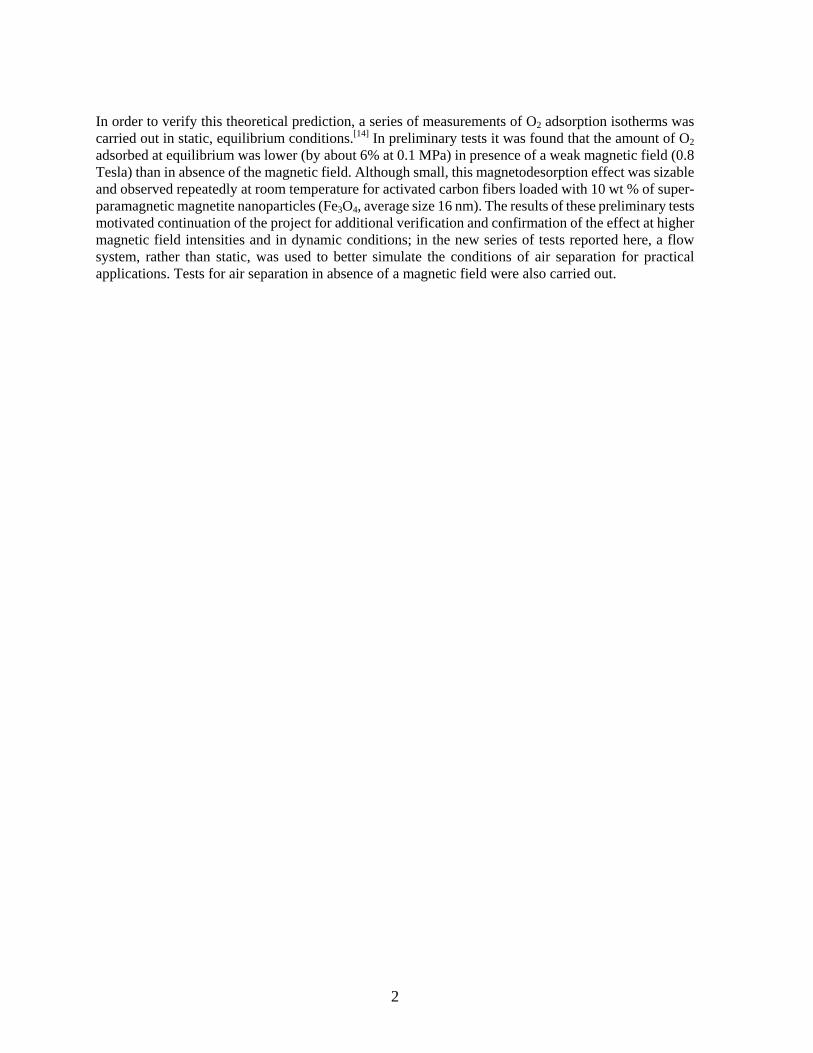
Figure 3: Differential distribution of pore volume as a function of pore width. Data calculated by DFT method from N2 adsorption and CO2 adsorption are plotted on a common logarithmic scale.
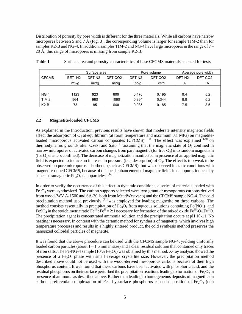
The results presented in Table 1 include the surface area values calculated from N2 adsorption data using the BET equation, and from the N2 and CO2 adsorption data using the DFT method; the pore volume calculated from N2 and CO2 adsorption data using the DFT method; and the average pore width calculated from the same adsorption data using the DFT method. Comparing the results reveals several differences between the three samples:
• Sample NG-4 has a relatively large surface area based on BET result (1123 m2/g) and DFT result from N2 adsorption (923 m2/g). In contrast, CO2 adsorption reveals lower surface area (600 m2/g), suggesting blockage of pore entrance by bulky oxidized surface groups, that may have been formed during the activation process.
• Sample TIM-2 has a slightly lower BET surface area (964 m2/g) and the DFT results for N2 adsorption (960 m2/g) and CO2 adsorption (1090 m2/g) are not much different. For this sample, both molecular probes used as adsorbate (N2 and CO2) give essentially the same pore volume (0.34 – 0.39 cc/g), which is a strong indication that the material is largely microporous. Indeed, the average pore width calculated by DFT method is 9.8 Å (based on N2 adsorption) or 5.2 Å (based on CO2 adsorption).
• Sample K2-B has a very small surface area value based on N2 adsorption data (73 m2/g from BET equation; 85 m2/g from DFT method). This contrasts with the large surface area measured by CO2 adsorption (640 m2/g based on DFT method), and is a strong evidence that the material contains very narrow micropores that cannot be accessed by N2 at 77 K, but are accessible to CO2 at 273 K. With an average pore width of 7.5 Å (based on N2 adsorption) or 3.5 Å (based on CO2 adsorption), the K2-B material is expected to have the most pronounced molecular sieving properties.
5
Distribution of porosity by pore width is different for the three materials. While all carbons have narrow micropores between 5 and 7 Å (Fig. 3), the corresponding volume is larger for sample TIM-2 than for samples K2-B and NG-4. In addition, samples TIM-2 and NG-4 have large micropores in the range of 7 – 20 Å; this range of micropores is missing from sample K2-B. Table 1 Surface area and porosity characteristics of base CFCMS materials selected for tests
Surface area Pore volume Average pore width CFCMS BET N2 DFT N2 DFT CO2 DFT N2 DFT CO2 DFT N2 DFT CO2 m2/g m2/g m2/g cc/g cc/g A A
NG 4 1123 923 600 0.476 0.195 9.4 5.2 TIM 2 964 960 1090 0.394 0.344 9.8 5.2 K2-B 73 85 640 0.035 0.185 7.5 3.5
2.2 Magnetite-loaded CFCMS As explained in the Introduction, previous results have shown that moderate intensity magnetic fields affect the adsorption of O2 at equilibrium (at room temperature and maximum 0.1 MPa) on magnetite-loaded microporous activated carbon composites (CFCMS). [14] The effect was explained [20] on thermodynamic grounds after Ozeki and Sato [13] assuming that the magnetic state of O2 confined in narrow micropores of activated carbon changes from paramagnetic (for free O2) into random magnetism (for O2 clusters confined). The decrease of magnetization manifested in presence of an applied magnetic field is expected to induce an increase in pressure (i.e., desorption) of O2. The effect is too weak to be observed on pure microporus adsorbents (such as CFCMS), but was observed in static conditions with magnetite-doped CFCMS, because of the local enhancement of magnetic fields in nanopores induced by super-paramagnetic Fe3O4 nanoparticles. [14] In order to verify the occurrence of this effect in dynamic conditions, a series of materials loaded with Fe3O4 were synthesized. The carbon supports selected were two granular mesoporous carbons derived from wood (WV A-1500 and SA-30, both from MeadWestvaco) and the CFCMS sample NG-4. The cold precipitation method used previously [21] was employed for loading magnetite on these carbons. The method consists essentially in precipitation of Fe3O4 from aqueous solutions containing Fe(NO3)3 and FeSO4 in the stoichimetric ratio FeIII : FeII = 2:1 necessary for formation of the mixed oxide FeIII
2O3.FeIIO. The precipitation agent is concentrated ammonia solution and the precipitation occurs at pH 10-11. No heating is necessary. In contrast with the ceramic method for synthesis of magnetite, which involves high temperature processes and results in a highly sintered product, the cold synthesis method preserves the nanosized colloidal particles of magnetite. It was found that the above procedure can be used with the CFCMS sample NG-4, yielding uniformly loaded carbon particles (about 1 – 1.5 mm in size) and a clear residual solution that contained only traces of iron salts. The Fe-NG-4 sample (10 % Fe3O4) was obtained by this method. X-ray analysis showed the presence of a Fe3O4 phase with small average crystallite size. However, the precipitation method described above could not be used with the wood-derived mesoporous carbons because of their high phosphorus content. It was found that these carbons have been activated with phosphoric acid, and the residual phosphorus on their surface perturbed the precipitation reactions leading to formation of Fe3O4 in presence of ammonia as described above. Rather than leading to homogeneous deposits of magnetite on carbon, preferential complexation of FeIII by surface phosphorus caused deposition of Fe2O3 (non

6
magnetic) and precipitation of ferrous hydroxide in the aqueous phase. 2.3 Zeolite A granular sample of zeolite X13 was also used for air separation tests in the flow system. Before packing in a chromatographic-type column, zeolite beads (1.5 - 2 mm) were pretreated at 140 oC for dehydration. 2.4 Experimental
All adsorbents in form of granules (1-2 mm) were packed in chromatography-type columns (copper tube, 50 cm long, ¼ inch diameter) which were rolled into a 3-coils spiral (5 cm diameter) that was placed flat between the poles of a water-cooled electromagnet (Applied Magnetics, model 2V1). The maximum field intensity between the magnet poles was 1.5 Tesla. Before packing in chromatography-type columns, all adsorbents were pre-dried overnight at 140 oC. After packing in the column all adsorbents were conditioned overnight in a flow of He (50 cc/min) at 150 – 200 oC. After conditioning the adsorbent, the flow of He was adjusted to the desired value for air separation tests (15 – 30 cc/min). The tests were performed by injecting controlled volumes of air through a septum upstream of the adsorbent column, and analyzing the composition of the gas downstream from the column. In a first series of tests the gas composition analysis was performed with a Hewlett Packard 5890 series II gas chromatograph (GC) equipped with thermal conductivity (TC) detector. The chromatograph was operated by Agilent ChemStation software for GC systems. It was found that the difference between thermal conductivities of oxygen and nitrogen is not large enough to afford separate identification of the components in a mixture using the TC detector. To correct that, the GC analysis of gas composition downstream the adsorbent column was replaced later by analysis by mass spectroscopy. A Vacuum Technology Inc. mass spectrometer (MS) was used, which was operated by the manufacturer’s software (VTI). The instrument was connected through a flow controlling valve and capillary tube to a derivation of the main gas line downstream the adsorbent column. This latter setup was proven more efficient for separate detection of oxygen and nitrogen concentration breaking through the column after air injection, even though the two components were poorly separated on the column.
7
3. AIR SEPARATION BASED ON MOLECULAR SIEVING EFFECTS
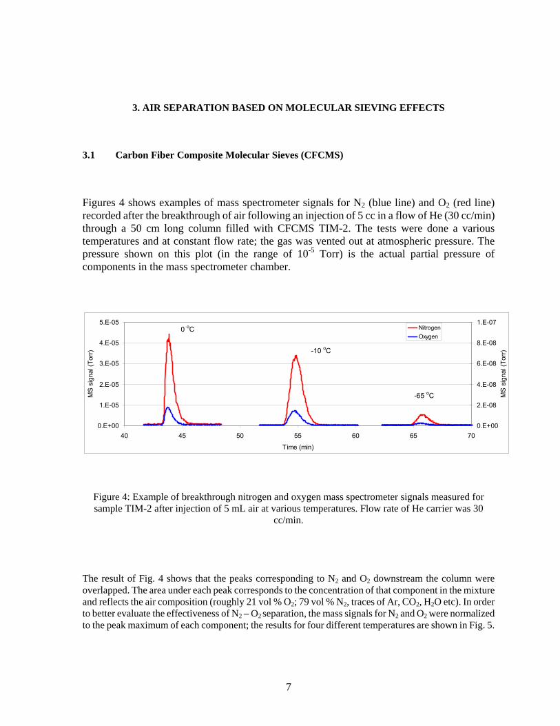
3.1 Carbon Fiber Composite Molecular Sieves (CFCMS) Figures 4 shows examples of mass spectrometer signals for N2 (blue line) and O2 (red line) recorded after the breakthrough of air following an injection of 5 cc in a flow of He (30 cc/min) through a 50 cm long column filled with CFCMS TIM-2. The tests were done a various temperatures and at constant flow rate; the gas was vented out at atmospheric pressure. The pressure shown on this plot (in the range of 10-5 Torr) is the actual partial pressure of components in the mass spectrometer chamber.
0.E+00
1.E-05
2.E-05
3.E-05
4.E-05
5.E-05
40 45 50 55 60 65 70
Time (min)
MS
sign
al (T
orr)
0.E+00
2.E-08
4.E-08
6.E-08
8.E-08
1.E-07
MS
sign
al (T
orr)
NitrogenOxygen
0 oC
-10 oC
-65 oC
Figure 4: Example of breakthrough nitrogen and oxygen mass spectrometer signals measured for sample TIM-2 after injection of 5 mL air at various temperatures. Flow rate of He carrier was 30
cc/min.
The result of Fig. 4 shows that the peaks corresponding to N2 and O2 downstream the column were overlapped. The area under each peak corresponds to the concentration of that component in the mixture and reflects the air composition (roughly 21 vol % O2; 79 vol % N2, traces of Ar, CO2, H2O etc). In order to better evaluate the effectiveness of N2 – O2 separation, the mass signals for N2 and O2 were normalized to the peak maximum of each component; the results for four different temperatures are shown in Fig. 5.
8
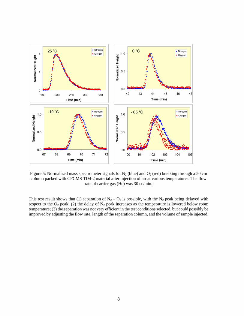
Figure 5: Normalized mass spectrometer signals for N2 (blue) and O2 (red) breaking through a 50 cm column packed with CFCMS TIM-2 material after injection of air at various temperatures. The flow
rate of carrier gas (He) was 30 cc/min.
This test result shows that (1) separation of N2 – O2 is possible, with the N2 peak being delayed with respect to the O2 peak; (2) the delay of N2 peak increases as the temperature is lowered below room temperature; (3) the separation was not very efficient in the test conditions selected, but could possibly be improved by adjusting the flow rate, length of the separation column, and the volume of sample injected.
0
1
1
180 230 280 330 380Time (min)
Nor
mal
ized
Hei
ght
Nitrogen
Oxygen 25 oC
0.0
0.5
1.0
42 43 44 45 46 47
Time (min)
Nor
mal
ized
Hei
ght
Nitrogen
Oxygen0 oC
0.0
0.5
1.0
100 101 102 103 104 105
Time (min)
Nor
mal
ized
Hei
ght
Nitrogen
Oxygen- 65 oC
0.0
0.5
1.0
67 68 69 70 71 72
Time (min)
Nor
mal
ized
Hei
ght
Nitrogen
Oxygen -10 oC
9
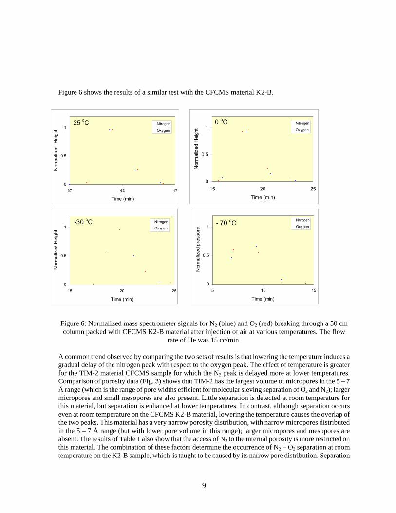
Figure 6 shows the results of a similar test with the CFCMS material K2-B.
Figure 6: Normalized mass spectrometer signals for N2 (blue) and O2 (red) breaking through a 50 cm column packed with CFCMS K2-B material after injection of air at various temperatures. The flow
rate of He was 15 cc/min. A common trend observed by comparing the two sets of results is that lowering the temperature induces a gradual delay of the nitrogen peak with respect to the oxygen peak. The effect of temperature is greater for the TIM-2 material CFCMS sample for which the N2 peak is delayed more at lower temperatures. Comparison of porosity data (Fig. 3) shows that TIM-2 has the largest volume of micropores in the 5 – 7 Å range (which is the range of pore widths efficient for molecular sieving separation of O2 and N2); larger micropores and small mesopores are also present. Little separation is detected at room temperature for this material, but separation is enhanced at lower temperatures. In contrast, although separation occurs even at room temperature on the CFCMS K2-B material, lowering the temperature causes the overlap of the two peaks. This material has a very narrow porosity distribution, with narrow micropores distributed in the 5 – 7 Å range (but with lower pore volume in this range); larger micropores and mesopores are absent. The results of Table 1 also show that the access of N2 to the internal porosity is more restricted on this material. The combination of these factors determine the occurrence of N2 – O2 separation at room temperature on the K2-B sample, which is taught to be caused by its narrow pore distribution. Separation
0
0.5
1
37 42 47
Time (min)
Nor
mal
ized
Hei
ght
Nitrogen
Oxygen
25 oC
0
0.5
1
15 20 25
Time (min)N
orm
aliz
ed H
eigh
t
Nitrogen
Oxygen
0 oC
0
0.5
1
15 20 25
Time (min)
Nor
mal
ized
Hei
ght
Nitrogen
Oxygen-30 oC
0
0.5
1
5 10 15
Time (min)
Nor
mal
ized
pre
ssur
e
Nitrogen
Oxygen- 70 oC
10
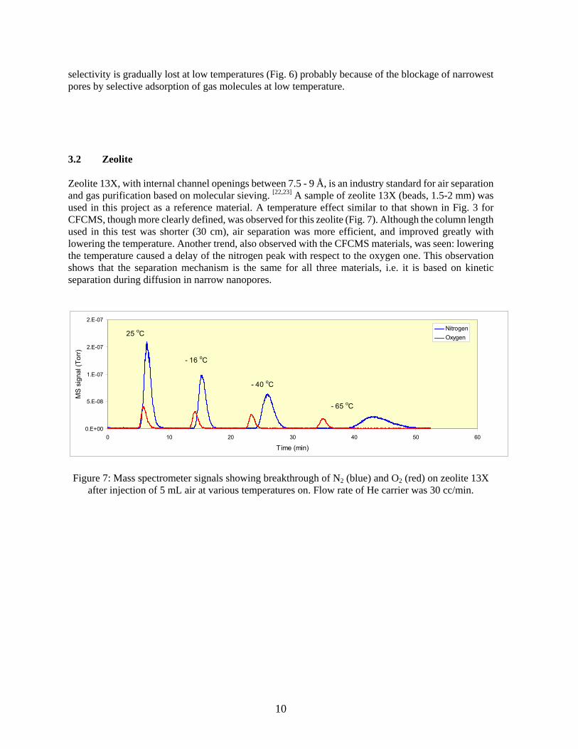
selectivity is gradually lost at low temperatures (Fig. 6) probably because of the blockage of narrowest pores by selective adsorption of gas molecules at low temperature. 3.2 Zeolite Zeolite 13X, with internal channel openings between 7.5 - 9 Å, is an industry standard for air separation and gas purification based on molecular sieving. [22,23] A sample of zeolite 13X (beads, 1.5-2 mm) was used in this project as a reference material. A temperature effect similar to that shown in Fig. 3 for CFCMS, though more clearly defined, was observed for this zeolite (Fig. 7). Although the column length used in this test was shorter (30 cm), air separation was more efficient, and improved greatly with lowering the temperature. Another trend, also observed with the CFCMS materials, was seen: lowering the temperature caused a delay of the nitrogen peak with respect to the oxygen one. This observation shows that the separation mechanism is the same for all three materials, i.e. it is based on kinetic separation during diffusion in narrow nanopores.
0.E+00
5.E-08
1.E-07
2.E-07
2.E-07
0 10 20 30 40 50 60
Time (min)
MS
sign
al (T
orr)
NitrogenOxygen
- 65 oC
25 oC
- 40 oC
- 16 oC
Figure 7: Mass spectrometer signals showing breakthrough of N2 (blue) and O2 (red) on zeolite 13X
after injection of 5 mL air at various temperatures on. Flow rate of He carrier was 30 cc/min.
11
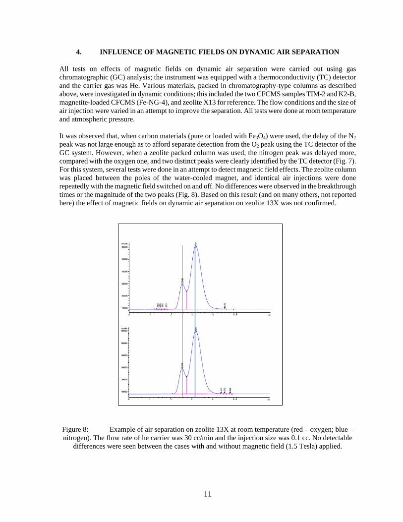
4. INFLUENCE OF MAGNETIC FIELDS ON DYNAMIC AIR SEPARATION All tests on effects of magnetic fields on dynamic air separation were carried out using gas chromatographic (GC) analysis; the instrument was equipped with a thermoconductivity (TC) detector and the carrier gas was He. Various materials, packed in chromatography-type columns as described above, were investigated in dynamic conditions; this included the two CFCMS samples TIM-2 and K2-B, magnetite-loaded CFCMS (Fe-NG-4), and zeolite X13 for reference. The flow conditions and the size of air injection were varied in an attempt to improve the separation. All tests were done at room temperature and atmospheric pressure. It was observed that, when carbon materials (pure or loaded with Fe3O4) were used, the delay of the N2 peak was not large enough as to afford separate detection from the O2 peak using the TC detector of the GC system. However, when a zeolite packed column was used, the nitrogen peak was delayed more, compared with the oxygen one, and two distinct peaks were clearly identified by the TC detector (Fig. 7). For this system, several tests were done in an attempt to detect magnetic field effects. The zeolite column was placed between the poles of the water-cooled magnet, and identical air injections were done repeatedly with the magnetic field switched on and off. No differences were observed in the breakthrough times or the magnitude of the two peaks (Fig. 8). Based on this result (and on many others, not reported here) the effect of magnetic fields on dynamic air separation on zeolite 13X was not confirmed.
Figure 8: Example of air separation on zeolite 13X at room temperature (red – oxygen; blue – nitrogen). The flow rate of he carrier was 30 cc/min and the injection size was 0.1 cc. No detectable
differences were seen between the cases with and without magnetic field (1.5 Tesla) applied.
12
5. CONCLUSIONS
The findings reported here confirm that CFCMS materials have the potential for separating O2 and N2 from air on the basis of the different diffusion rates of the two molecules through the composite. The experimental data show that under dynamic conditions, nitrogen diffusion through the extended pore system of microporous adsorbents is slower than that of oxygen, and becomes even slower as the temperature is decreased. Carbon fiber molecular sieves thus have potential for N2 - O2 separation, provided that an improved and tailored porosity is achieved, so that pore widths are comparable to the molecular dimensions of the gas components being targeted. This improvement will depend on the identification and demonstration of alternative techniques for the activation of carbon materials, and/or on the use of new carbon precursors (such as lignin) that are known to produce extensive networks of uniformly narrow micropores. The effect of magnetic fields on air separation was not confirmed at room temperature for zeolite 13X and for Fe3O4-loaded CFCMS in dynamic conditions. It is presently unclear whether this conclusion can be extrapolated for other materials or other condision, given that this finding under dynamic conditions is in contrast with previous data obtained under static (equilibrium) conditions. In order to reach acceptable conclusions concerning this aspect of the work, more sophisticated measurements under higher intensity magnetic fields are required. This would verify the preliminary data and determine if magnetic fields can be exploited for the separation of O2 and N2 from air. Furthermore, as shown in the data, efficient air separation is achieved using zeolite as the separating medium. In conclusion of this report, the data as a whole shows there is much evidence that a combined material for separation could be exploited so that initial air separation is done using zeolite while a second-stage purification or oxygen enrichment on carbon molecular sieves, notably CFCMS, to exploit the electrical swing adsorption capability of these materials, would be of much additional value.
13
REFERENCES
1. Burchell, T. D., Judkins, R. R., Rogers, M. R., and Williams, A. M., A Novel Process for the Separation of Carbon Dioxide and Hydrogen Sulfide for Gas Mixtures, CARBON, 35 (1997) 1279-1294.
2. Burchell, T. D., Weaver, C. E., Chilcoat, B. R., Derbyshire, F., and Jagtoyen, M., Activated Carbon Fiber Composite Material and Method of Making, U.S. Patent 6,030,698 (February 29, 2000) Assigned to Lockheed Martin Energy Research Corporation.
3. Burchell, T. D., Weaver, C. E., Chilcoat, B. R., Derbyshire, F., and Jagtoyen, M., Activated Carbon Fiber Composite Material and Method of Making, U.S. Patent 6,258,300 (July 10, 2001) Assigned to UT-Battelle, LLC.
4. Burchell, T. D., and Judkins, R. R., A Novel Carbon Fiber Based Material and Separation Technology, Energy Conservation and Management, 38 Supplement, S99-S10 (1997).
5. Wilson, K. A., Burchell, T. D., and Judkins, R. R., Carbon Fiber Composite Molecular Sieve Electrically Regenerable Air Filter Media, U. S. Patent 5,827,355, (October 27, 1998), Assigned to Lockheed Martin Energy Research Corporation.
6. Judkins, R. R., and Burchell, T. D., Gas Separation Device Based on Electrical Swing Adsorption, U. S. Patent 5,972,077 (October 26, 1999) Assigned to Lockheed Martin Energy Research Corporation.
7. Burchell, T. D., Omatete, O., Gallego, N. C., and Baker, F. S., Novel Activated Carbon Composites for Air Separation, Proceedings of the 18th Annual Conference on Fossil Energy Materials, Knoxville, TN, June 2-4, 2004.
8. Kaneko, K., Fukuzaki, N., and Ozeki, S., The Concentrated NO Dimer in Micropores Above Room Temperature, J. Chem. Phys., 87 (1987) 776-777.
9. Takaishi, Y., Dimers of Oxygen Molecules in the Pores of Ca6A Zeolite, J. Chem. Soc. Faraday Trans., 93 (1997) 1257-1260.
10. Yamamoto, I., Yamaguchi, M., Goto, T., and Miura, S., Chemical Equilibrium of the Ferromagnetic LaCo-H5 System in Strong Magnetic Fields, J. Alloys Compounds, 231 (1995) 205-207.
11. Ozeki, S., Wakai, C., and Ono, S., Is Magnetic Effect on Water Possible?, J. Phys. Chem., 95 (1991) 10557-10559
12. Miyamoto, J., Matsubara, Y., Kurashima, H, Tazaki, T., and Ozeki, S., Magnetic Field Effects on Physical Adsorption Equilibrium Between Solids and Gases of Organic Molecules and Oxygen, Nippon Kinzoku Gakkaishi, 61 (1997) 1300-1305.
13. Ozeki, S., and Sato, H., Magnetic Interactions in Adsorption at Solid Surfaces, in Encyclopedia of Surface and Colloid Science, Marcel Dekker, New York, pp. 3120-3131 (2002).
14. Baker, F. S., Contescu, C. I., Tsouris, C., and Burchell, T. D., Activated Carbon Composites for Air Separation, Proceedings of the 20th Annual Conference on Fossil Energy Materials, Knoxville, TN, June 12-14, 2006.
15. Brunauer, S., Emmett, P. H., and Teller, E., Adsorption of Gases in Multimolecular Layers, J. Am. Chem. Soc., 60 (1938) 309-319.
16. Gregg, S. J., and Sing, K. S. W., “Adsorption, Surface Area and Porosity”, 2nd Edition, Academic Press, London (1982).
17. Lastoskie, C., Gubbins, K. E., and Quirke, N., Pore Size Distribution Analysis of Microporous Carbons: A Density Functional Theory Approach, J. Phys. Chem., 97 (1993) 4786-479.
14
18. Jagiello, J., and Thommes, M., Comparison of DFT Characterization Methods Based on N2, Ar, CO2, and H2 Adsorption Applied to Carbons with Various Pore Size Distributions, CARBON, 42 (2004) 1227-1232.
19. Rodriquez-Reinoso, F. and Linares-Solano, A., Microporous Structure of Activated Carbons as Revealed by Adsorption Methods, in “Chemistry and Physics of Carbon”, Edited by P. A. Thrower, Volume 21, pp. 1-146, Marcel Dekker, New York (1988).
20. Baker, F. S., Contescu, C. I., Tsouris, C., Gallego, N. C., and Burchell, T. D., Carbon Fiber Composite Molecular Sieve for Air Separation, Extended Abstracts, Carbon 2006 International Conference, Aberdeen, Scotland, July 16-21, 2006.
21. Spacu, P., Brezeanu, M., Patron. L., Contescu, A., and Crisan, D., Coordination Compounds as Raw Materials for Mixed Oxides, Thermochimica Acta, 178 (1991) 231-239.
22. Jee, J.-G., Lee, J.-S., and Lee, C.-H., Air Separation by a Small Scale Two-Bed Medical O2 Pressure Swing Adsorption, Ind. Eng. Chem. Res. 40 (2001) 3647-3658.
23. Jee, J.-G., Lee, S.-J., Moon, H.-M., and Lee, C.-H., Adsorption Dynamics of Air on Zeolite 13X and CMS Beds for Separation and Purification, Adsorption 11 (2005) 415-420.


![Activated Carbon[1]](https://static.fdocuments.us/doc/165x107/56d6be9b1a28ab301692d8de/activated-carbon1.jpg)