ACO Tiefbau - . instructions. ACO Tiefbau. ACO Stormbrixx – a modular infiltration system. User...
16
Installation instructions ACO Tiefbau ACO Stormbrixx – a modular infiltration system User guidelines for installation and commissioning of rainwater infiltration and retention systems
Transcript of ACO Tiefbau - . instructions. ACO Tiefbau. ACO Stormbrixx – a modular infiltration system. User...

I n s t a l l a t i o n i n s t r u c t i o n s
ACO T i e f b a u
ACO Stormbrixx – a modular infiltration system
User guidelines for installation and commissioning
of rainwater infiltration and retention systems

2
Installation instructions
Contents
The ACO drainage channel collects the surface water and channels it via the outlet shaft into the ACO plastic sedimentation shaft where the solids are separated from the rainwater. Via the outflow gulley the rainwater is first collected in the ACO Stormbrixx infiltration system and then gradually released into the ground.
Practical examples
The ACO yard drain collects and filters the surface water and feeds it directly into the ACO Stormbrixx infiltration system where it gradually seeps out.
ACO Stormbrixx Product Description 3
Construction Design Technical Data 4
Logistics and Handling 6
Transport and Storage 6
Ground Rules for Installing ACO Stormbrixx 7
Excavating the Pit and Creating the Supports 8
Laying the Filter Fleece 8
Installing the Basic Elements 9
Installing the Lower and Middle Shaft Sections 9
Installing the Connectors 10
Installing the Side-walls 10
Installing the Coverings 11
Installing the Connectors/Pipe Adaptors 11
Installing the Upper Sections 12
Shaft Cover SA 400 with/out Air Vents 14
Covering over (Infilling/Covering) 14
Retention 15
Quality Assurance during and after Construction Work 15
Downpipe Yard drain downpipe with downpipe connector
Ventilation/inspection
Outflow
Inflow Outflow
Outflow
Green area
Inflow
Outflow
3
Installation instructions
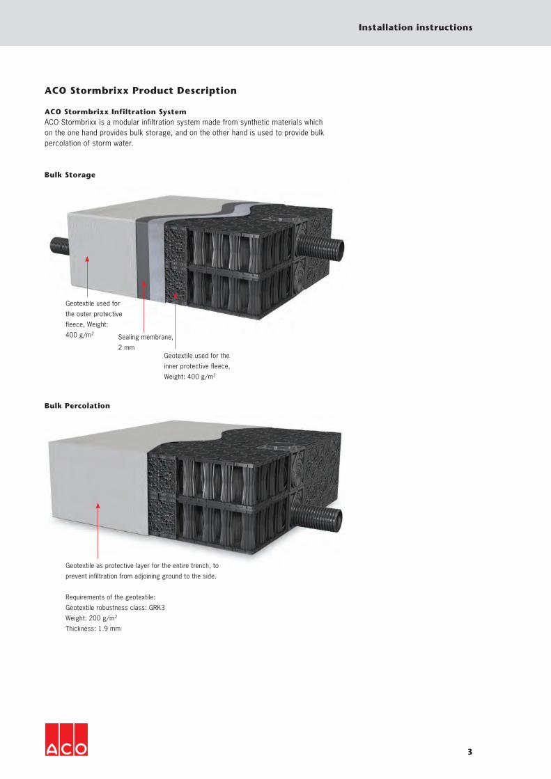
ACO Stormbrixx Product Description
ACO Stormbrixx Infiltration SystemACO Stormbrixx is a modular infiltration system made from synthetic materials which on the one hand provides bulk storage, and on the other hand is used to provide bulk percolation of storm water.
Geotextile used for
the outer protective
fleece, Weight:
400 g/m2
Bulk Storage
Bulk Percolation
Sealing membrane,
2 mmGeotextile used for the
inner protective fleece,
Weight: 400 g/m2
Geotextile as protective layer for the entire trench, to
prevent infiltration from adjoining ground to the side.
Requirements of the geotextile:
Geotextile robustness class: GRK3
Weight: 200 g/m2
Thickness: 1.9 mm

4
Installation instructions
Dimension Weight Item number
Length Width Heights[mm] [mm] [mm] [kg]
Basic element
120034
2
600
305
1200 600 342 10,0 314020
Side wall
582
587
582 587 55 1,6 314021
Cover
548
320
548 548 43 0,8 314022
Construction Design Technical Data

5
Installation instructions
Accessories
Description Used with Weight Item [kg] number
Connector � to connect basic elements to each other
to connect two layers: combine 2 connectors
� number of connectors when installing 2 layers: 1/2 the total number of basic elements for the entire trench
� number of connectors when installing 3 layers: 2/3 the total number of basic elements for the entire trench
� ACO Stormbrixx basic element
0,1 314023
Adapter for Pipe Connection
� ACO Stormbrixx basic element
Ø 110 0,4 314026
Ø 160 0,7 314027
Ø 200 1,3 314028
Ø 315
Ø 400
3,3
4,5
314029 314030
upper section � for inspection and washing access to the infiltration system
� with formwork
� ACO Stormbrixx basic element
2,6 314038
Upper part with socket � for inspection and rinsing access to the infiltration system
� Ø 160 � with formwork
� ACO Stormbrixx basic element
2,8 314039
Shaft Lower and Middle Sections � for access to infiltration system � for connecting inlets and outlets within the infiltration system
� dimensions: 594 x 594 x 610 mm
� connectors Ø 400 32,0 27034
SA 400 Shaft cover � load class D 400 � made from EN-GJL cast iron � clear width 400 � no air vents
� inspection and rinsing shaft
38,0 314043
Schachtabdeckung SA 160 � access for inspection � access for inspection � made from EN-GJL cast � clear width 160 � no air vents
� connectors Ø 160 15,7 314044

6
Installation instructions
The ACO Stormbrixx infiltration system (basic elements, side walls and covers) stacks perfectly for ease of transport. The basic elements fit into each other precisely, which reduces the volume to be transported by more than half com-pared to traditional systems.Transport costs and CO2 emissions are substantially reduced.
Logistics and Handling
Ideal stacking reduces transport costs Example: Project A requires a storage volume of 280 m³. Using ACO Storm-brixx the infiltration system components can all be transported on a single vehic-le. For other systems up to four vehicles would be needed
The reduced space required, thanks to basic
elements which stack perfectly, and simple
handling on site both help to reduce logistics
costs.
Transport and Storage
Basic element pallet size: 1.22 x 0.61 m pallet height: 1.33 m height of two pallets: 2.33 m weight/unit: approx. 10 kg units/pallet: 16 per pallet or 32 per double pallet
Side wall pallet size: 1.20 x 1.20 m pallet height: 1.17 m height of two pallets: 2.34 m weight/unit: approx. 1.6 kg units/pallet: 100 per pallet
Cover large box: 56 x 56 x 81 cm units per box: 18 per box boxes per European pallet: 6 per pallet
units/pallet: 108 units pallet height: 1.83 m weight/unit: approx. 0.80 kg weight per box: 14.4 kg
Connectors weight: approx. 0.015 kg packaging unit (PE) of 50 units
Basic element double pallet Cover
Side wall

7
Installation instructions
Transport instructions:The pallets must be transported around the construction site using your own equipment.
Storage instructions (including temporary storage):The ACO Stormbrixx system can be stored outdoors. When storing tempora-rily make sure the ground is flat and so-lid. To prevent accidents, stack to only a maximum height of 2 pallets (32 basic elements, 2.33 m high). For long-term storage at the construction site these double-height pallets need to be secured against stormy conditions. The basic elements should, if possible, be stored in such a way that they are protected
from direct sunlight (stored in a shaded area or covered with a light-coloured geotextile, in which case care must be taken that heat is not trapped under the cover). If this is not possible, then they may only be covered over after installation once they have been cooled off (perhaps the following morning). Outdoor storage should never exceed one year.
Ground Rules for Installing ACO Stormbrixx
Personal Protective EquipmentPersonal protective equipment is requi-red for various activities relating to the installation. Protective equipment from expert suppliers must be provided to your staff in sufficient quantities, and its use must be enforced by supervisors.
Instruction sign Meaning Explanation
Wear safety shoes
Safety shoes offer good non-slip protection, especially in wet areas, and resistance to piercing, e.g. by nails, and also protect the feet from falling objects, e.g. when moving items
Wear a safety helmet Safety helmets protect from head injuries e.g. from falling objects or blows
Wear hearing protection Ear protectors protect your ears from damage when noise levels are excessive
Wear protective goggles or glasses
Protective glasses protect your eyes from mechanical injuries caused by dust, acid, fragments, blows or knocks.
Wear safety gloves Protective gloves protect the hands from minor bruises and cuts, particularly during transport, commissioning, maintenance, repairs and dismantling

8
Installation instructions
The underlying ground must be strong enough to bear the load and be able to absorb percolated water. If the underly-ing subsoil is not solid, then the geologi-cal structures must be investigated and suitable measures must be taken. The solid substrate must be prepared so that it is free of stones, even and without gradient. Use your own equipment to remove the excavated soil.The support consists of the surround-ing subsoil or any substitute covering added, and must be able to bear a load
Excavating the Pit and Creating the Supports
of EV2 ≥ 45 MN/m², and it must have a cleaning layer (chippings/gravel) of 2/8 grade, approx. 5 cm thick. This cleaning layer must be levelled off. The com-pacted layer (substrate) must still be permeable after it has been compacted. The quality of this support is critical for the rest of the installation, and will have a significant impact on the stability and strength of the storage components, particularly in the case of multi-layer constructions or those subject to major loads (earth/traffic load).
For percolation, the whole of the trench must be wrapped in filter fleece (geo-textile robustness class: GRC 3, weight: 200 g/m², thickness: 1.9 mm). Before starting to lay the basic elements the fleece must be laid over the cleaning layer. The fleece should overlap to the sides sufficiently to allow the entire ins-tallation to be wrapped. ACO Stormbrixx are completely surrounded with the filter fleece to prevent the penetration of fine
Laying the Filter Fleece
particles of earth. The fleece needs to be laid diagonally to the main axis of the trench. When measuring the fleece, the following applies: Length of the fleece strips = size of trench + at least 0.50 m overlap. The overlap between any strips which are laid end-to-end should also be at least 0.50 m. Both ends of the geotextiles are attached temporarily but securely to the trench embankments and edges. After completing the installation
The ACO Stormbrixx infiltration system may require an official permit: this must be checked before installing it. During the planning phase, the relevant official and legal requirements, currently appli-cable technical standards and the DWA (German Association for Water, Waste-water and Waste) work instructions must be taken into account.
The system must not be installed long-term or at times in standing groundwa-ter, stratum water or flood waters. The recommendations of the DWA-A 138 work instructions in this respect apply to trench infiltration systems and must be applied. These indicate that the distance from the average highest groundwater level must be at least 1.0 m.
Please note: During construction of the embank-ments/working space/shoring (DIN 4124) and excavation (DIN 18300), the currently applicable standards and accident prevention regulations must be observed.
of the ACO Stormbrixx, the filter fleece will be detached from the sides and edges of the trench and laid over the filtration system with a minimum of 0.50 m overlap between the strips of fleece. Take care that the fleece is laid snugly against the ACO system so that no soil can infiltrate between the ACO Storm-brixx system and the fleece wrapper.
Please note!Take care that the overlaps are always at least 50 cm, that the fleece surface is completely sealed and that it cannot fall open during in-fill.

9
Installation instructions
Installing the Basic Elements
The company contracted for the installa-tion is responsible for this being carried out correctly. The basic elements must be inspected for damage before instal-lation. Components can be damaged during transport to or around the const-ruction site at low temperatures (below 5 °C). Damaged basic elements, side walls, covers, connectors, pipe adaptors and shaft covers must not be installed!
A basic element consists of eight pillars, four with male and four with female con-nections. The basic elements are to be set out on the geotextile as shown in the planning/installation diagram.
When combining them, we recommend putting them in place already connected, as this improves the stability of the enti-re trench block. They need to be aligned so that there is an inspection space between the pillars. We recommend that each layer of the ACO Stormbrixx sys-tem (a layer consists of two basic ele-ments) is organised following a diagram showing how to connect the layers, based on the installation principles.
Basic elements
Installing the Lower and Middle Shaft Sections
The lower and middle shaft sections are integrated into the overall system and provide access in up to four directions through the infiltration system for ins-pection and maintenance. For multi-layer infiltration systems, the lower and midd-le shaft sections are simply stacked on top of each other. The inner diameter of the shaft lining in the lower and middle shaft sections is 400 mm. If needed, a pipe connection point of SD/OD 110, 160, 200, 250, 300 or 400 can be cut out using a jigsaw along the cutting/sawing marks provided. The lower shaft section is placed on the geotextile inside the infiltration system.

10
Installation instructions
When connecting two or three layers the layers are linked to each other and locked into place using pairs of linked connectors.
When installing the lower and middle shaft sections connectors are used to connect these to the basic elements. No connectors are used on the base!
The exact position of the connectors within the overall trench infiltration sys-tem can be seen on the diagram of the installation principles!
All the external sides of the trench system are closed off using side-walls which are inserted into the openings provided in the basic elements and which click into place. The side wall perimeters for the entire system offer a clean base surface for the geotextile wrapper. If needed, a pipe connection point of SD/OD 110, 160, 200, 250, 300 or 315 can be cut out along the cutting/sawing marks provided. The side walls have a predefined saw matrix for the connection of plastic pipes of SD/OD 110 to 315, which can be cut out using a jigsaw.
Installing the Connectors
Installing the Side-walls
Tab clip
Positioning tab
When installing the side walls you must ensure that the positioning tab is inser-ted into the base element first.
X X
X X

11
Installation instructions
The covers provide a clean surface for laying the wrapping geotextile and are placed only on the top layer of the basic elements, before installing the fleece! They prevent the fleece being forced into the necks of the pillars.
Installing the Covers
Creating the Openings
Tools required/permittedA jigsaw with extra long blades is nee-ded for cutting out the openings for the pipe ducts in the side walls, on the top of the basic elements and in the lower and middle shaft sections. Use a drill to get the saw blade inserted when creating the openings in the lower shaft section.
Installing the Connectors/Pipe Adaptors
The openings are marked on the geotextile using a permanent marker and are cut open using a
Stanley knife.
Cutting out the pipe connection adaptor opening in the side wall

12
Installation instructions
Bisecting the basic element
Before installing the basic elements the openings for ventilation in both directions, and for inspection access must be cut out of each basic element.
Inserting the Pipe Connection Adaptor
The pipe adaptors must be used for direct pipe connections to the lower and middle shaft sections, the side walls and to basic elements. After cutting out the openings with a saw and positioning the fleece around the trench, the holes for the adaptors are created in the fleece. The pipe adaptor is held against the fleece and its inside diameter is marked
on the fleece. Within the circle marked, a cross is cut and the pipe adaptor is pushed together with the fleece into the component until the pipe adaptor‘s flan-ge is lying flush against the component (= sand-proof). The pipe connection ad-aptors can be used to connect KG pipes of nominal diameters SD/OD 110, 160, 200, 250, 315 and 400.
Creating the hole in a side wall and in a basic element.
This side is inserted into
the filtration system!
Installing the Upper Sections
The upper sections with and without sockets for the inspection and washing elements can be rotated around the pipe axis and can be adjusted using their push-fit connection to suit the local gra-dients in all directions, and their height can be telescoped (+/- 30 mm) and they are watertight to 0.5 bar. The pipe adap-
tor without a socket is held against the fleece and its inside diameter is marked on the fleece. Within the circle marked, a cross is cut and the upper section (wi-thout a socket) is pushed together with the fleece into the opening, creating a sand-proof connection. Before inserting the upper sections, remove the protecti-
ve film from the seal and clean the seal. The seals must be coated with a suitable lubricant. The upper section must be in-serted to at least the minimum insertion depth!

13
Installation instructions
Covers with and without so-
ckets with formwork
Creating the Holes
Drawing the inner diameter Cutting a cross within the marked circle Installing the intermediate section
Access to the Infiltration SystemThe ACO Stormbrixx infiltration system can be accessed from two different points. Through the ACO Stormbrixx upper section (internal diameter = 339 mm) together with the lower and inter-mediate shaft sections (internal diameter = 400 mm), which allow passage of the camera and also pressure washing. Through the vertical SD/OD 160 access which only supports inspection of the infiltration system.
ACO Stormbrixx
vertical access
Ø 400
ACO Stormbrixx
upper section (internal)
ACO Stormbrixx
vertical access
Ø 160
Ventilation The bi-directional ventilation system is installed after placing the fleece in the trench, and after installing the pipe adaptor on the box. After installation of the bi-directional ventilation system the other upper sections are installed. In the upper sections load spreading is ensured thanks to the telescoping which is activated between the components.
Any subsidence in the filled area can be coped with by the tolerance window pro-vided by the telescoping.
Vertical access SD/OD 160After laying the fleece and installing the SD/OD 160 pipe connection adaptor on the box, an SD/OD 160 KG pipe made from PP is sat on top of this, up to
7.0 cm below the planned ground sur-face level. The upper end of the KG pipe is closed off with a temporary cap until the permanent cover is installed. Thanks to the separation in the construction of the upper section and the KG pipe, the shaft cover transfers the load from passing traffic in full to the neighbouring base courses.

14
Installation instructions
Shaft cover SA 400 with/out air vents
The cover and frame are made from cast iron. The shaft cover has a mainte-nance-free, screw-free and traffic-safe catch made from highly wear-resistant plastic (conforms 100% to DIN EN 124 / E DIN 1229, is stable at extreme temperatures, repels dirt, is self-locking and vandal-proof). After putting the co-ver in place, step vertically on the area
protruding above the frame to lock it into place. A concrete seating surroun-ding the upper section provides the load transmission for the shaft cover. A concrete seating C12/15 approx. 20 cm wide is created all the way around, as defined by DIN EN 206-1, and raised by 2 cm to the highest drain upper section. Use the inserted temporary cover/form-
work to smooth off the inserted concre-te flush. Then remove the temporary co-ver/formwork, press the frame into the wet cement base to a depth of approx. 2 cm until it is completely seated on the upper shaft section or as required for the final height.
Covering over (Infilling/Covering)
Side infilling (material DIN 18196) is to be carried out according to DIN EN 1610, in layers, up to the upper edge of the trench. Compact the fill material with a light-weight compactor to a Proctor value of approx. 97%. Avoid any contact between the compactor and the plastic components. The filling and sealing is done with temporary covers/formwork in place for the top components.ExcavationsRecognised good technical practice, and applicable laws and standards must be
SLW 60[mm]1)
SLW 30[mm]
No vehicle load[mm]
Min. soil cover 1000 1) 1000 1) 800
Max. soil cover 3300 3500 3700
Standard soil cover for installation of the ACO Stormbrixx infiltration system
respected (such as „Additional technical specifications and guide lines for soil works in road constructions“ (E-StB), „Directive for standardisation of upper surfaces for road constructions“ (RstO) etc). MaterialThe stone-free infill material must be compactable and able to absorb perco-lated water.The coefficient of permeability of the infill material must at least match the calculated kf value.
ProcedureThe insertion of the infill material must not create any problematic distortion, damage or inappropriate loading of the system. The infill material must be intro-duced evenly on all sides, in layers of ≤ 30 cm at a time. The compaction may only be carried out using medium com-pacting equipment to a proctor density of Dpr ≥ 97 %.Care must be taken when infilling and compacting that the overlaps of the geotextile are not disturbed and pulled apart, and that the ACO Stormbrixx sys-tem is not damaged!
E =45 MN/m²v2
Auflager
verdichtungsfähiger Baugrund
Verfüllung nach ZTVE-StBverdichtungs-/versicker-
Planum
ungsfähiges Material
Verkehrsfläche (Oberbau gemäßgültiger Richtlinien z.B. RStO )
35 cm Schotter10 cm verdichtungsfähigessteinfreies Material
Arbeitsraum nach DIN 4124
5 cm Sauberkeitsschicht 2/8
ACO Stormbrixx
Supports
Infilling according to ZTVE-StB regulationscompactable material
Flat surface Ev2=45 MN/m²
which allows infiltration
Traffic surface (upper surface asper current regulations e.g. RStO)
35 cm cover consisting of load-bearing material e.g. road metal
10 cm compactable stone-free material
Working width as per DIN 4124
5 cm cleaning layer 2/8
ACO Stormbrixx
compactable and load-bearing substrate
1) Ground cover consisting of cover and upper surface as per RStO regulations

15
Installation instructions
CoveringAfter completing the infilling around the sides, a compacted covering of 10 cm of stone-free filler material and a 35 cm thick load-bearing layer of e.g. road metal are placed over the infiltration system to crea-te a flat base for the subsequent struc-ture. Covering the ACO Stormbrixx system must be done in layers, tipping materials from the edge using a light-weight back-hoe or wheel loader. This equipment may
only be driven over the site once it is covered by a sufficiently compacted layer with a thickness of ≥ 45 cm, while taking care not to create tracks.
For surfaces which will carry traffic the current road construction regulations ap-ply (RStO). During and after the construc-tion phase care must be taken to ensure that no dirt enters the infiltration system.
Please note!Compaction using heavy vibrating rollers is not permitted! Driving construction vehicles directly over the ACO Stormbrixx system is not permitted! Driving heavy construction vehicles directly over the ACO Stormbrixx system is only permitted when there is a compacted covering at least 100 cm thick.
Retention
If retention is required, then the ACO Stormbrixx modular filtration system must be wrapped in a watertight combination of protective fleece/sealing membrane/protective fleece, and welded. The sealing membrane must be protected inside and out against mechanical damage by a pro-tective fleece. The pipe adaptor and the shaft neck in the lower shaft section must be welded to the sealing membrane. The
welding of the sealing membrane must be carried out by qualified welders and the welded seams must be inspected as per the DVS (German Welding Association) gui-delines. The water-tightness of the seams must be proven and inspection reports to this effect must be presented to the cus-tomer. This work must be carried out by a specialist company with certified plastic welding equipment.
Geotextile,
external protective fleece
sealing membrane
Geotextile,
internal protective fleece
Please note!Take care that the fleece surface is com-pletely sealed and that no holes are crea-ted during infill!
Quality Assurance during and after Construction Work
The suitability of the construction ma-terials to be supplied by the contractor must be demonstrated to the customer.
Goods receipt inspection of the mate-rials used e.g. construction materials (ACO system, fleece, infill material ...)
Labelling Damage Completeness Measured load-bearing ability and evenness of the supporting (proof to be supplied)
Fleece on supports (no folds, correct overlaps) visual inspection and mea-surements
Layout plan followed, visual confir-mation
Fleece wrapping/accessories (intermediate acceptance prior to infil-ling), visual inspection
Insertion of infill material (proof of compaction), measurements
Final acceptance (documentation of the processes, infiltration and reten-tion, to be kept separate, for mass retention the water-tightness must be checked, and the inspection records for the seams)
Possibly, control inspection by the customer. Visual inspection by means of TV passage (with record) through the installation
If providing retention: Weld seams. Test water-tightness by filling with water up to ground-level
The infiltration system must only be made functional after acceptance of the construction. Penetration by roots into the infiltration system must be avoided by following a suitable planting plan. We recommend that where trees either already exist or are to be planted, that a minimum distance of half the potential crown diameter be maintained (in additi-on to using root protection foils).
Operation of the system
Please note!For each application site you need to take into account the load represented by the soil and traffic. ACO Civil Engineering application technology can advise what is required, based on the details of the proposed construction. Unusual construction conditions will require individual inspection and this should be arranged with ACO Civil Engineering application systems. The approval of these unusual construction conditions must be given by the construction company and/or the building supervi-sor/planner.
ACO Tiefbau Vertrieb GmbH
PO Box 32024755 RendsburgAm Ahlmannkai24782 BüdelsdorfTel. +49 (0)4331 354-500Fax +49 (0)4331 354-358
PO Box 112597661 Bad KissingenNeuwirtshauser Straße 1497723 OberthulbaTel. +49 (0)9736 41-50Fax +49 (0)9736 41-21
/201
2
Cha
nges
may
occ
ur
Drainage channels
Road and yard drains
Top sections
Manhole covers
Separators
Protecting watercourses
Bulk storage and bulk percolation
Pumping stations
Tree grids
Every product from ACO Civil Enginee-ring supports the ACO system series
ACO. The future of drainage.