ACI STRUCTURAL JOURNAL TECHNICAL PAPER Shear Design ... · PDF fileShear Design Consideration...
7
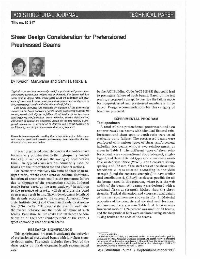
ACI STRUCTURAL JOURNAL TECHNICAL PAPER Title no. 85-S47 Shear Design Consideration for Pretensioned Prestressed Beams by Kyuichi Maruyama and Sami H. Rizkalla Typical cross sections commonly used for pretensioned precast crete beams are the thin-webbed tees or channels. For beams with {ow shear span-to-depth ratio, where shear could be dominant, the pres- ence of shear cracks may cause premature failure due to slippage 0/ the prestressing strands and alter the mode of failure. This paper discusses the influence of slippage of the prestressing strands on the beam behavior oj pretensioned prestressed concrete tee beams, tested staticaffy up to failure. Contribution of various shear reinforcement configuration, crack behavior, overall de/ormation, and mode of failure are discussed. Based on the test results, a prOM posed mechanism is introduced to describe the overall behavior of such beams, and design recommendations are presented. Keywords: beams (supports); cracking (fracturing); deformation; failUre; pre- cast concrete; prestressed concrete; pretensloningi shear properties; slippage; strains; stresses; structural design. Precast prestressed concrete structural members have become very popular due to the high-quality control that can be achieved and the saving of construction time. The typical cross sections commonly used for beams are the thin-webbed tee and channel sections. For beams with relatively low ratio of shear span-to- depth ratio, where shear stresses become dominant, initiation of shear crack could cause premature failure due to slippage of the prestressing strands. Induced tensile forces based on the truss analogy, '" in addition to the presence of cracks, will deteriorate the bond stresses and result in insufficient development length of the strands according to the current American Con- crete Institute (ACI) and Canadian Standards Associa- tion (CSA) codes.'" Slippage of the strands could alter the overall behavior and the mode of failure of such beams. Premature failure could also influence the con- tribution of the shear reinforcement of the various types commonly used for such beams. RESEARCH SIGNIFICANCE This experimental program investigates the behavior of pretensioned prestressed beams with low shear span- to-depth ratio. The study includes the effect of the sqear cracks on the development length recommended 492 by the ACI Building Code (ACI 318-83) that could lead to premature failure of such beams. Based on the test results, a proposed concept to describe the failure mode for non prestressed and prestressed members is intro- duced. Design recommendations for this category of beam are presented. EXPERIMENTAL PROGRAM Test specimen A total of nine pretensioned prestressed and two nonprestressed tee beams with identical flexural rein- forcement and shear span-to-depth ratio were tested statically up to failure. The prestressed beams were reinforced with various types of shear reinforcement including two beams without web reinforcement, as given in Table I. The different types of shear rein- forcement were conventional double-legged, single- legged, and three different types of commercially avail- able welded wire fabric (WWF). For a constant stirrup spacing s of 152 mm, * the steel area of the shear rein- forcement A, was selected according to the yield strength /y and the concrete strength /: to have similar steel contributionA,/ylb.s/; as close as possible for all the beams tested in this program, where b w is the web width of the beam. All beams were designed with a nominal flexural strength higher than the shear strength. Typical dimension and cross-sectional details of the test specimen are shown in Fig. I. Material properties of the concrete and the steel used for shear reinforcement are given in Table 1. A tension rein- forcement ratio of 1.24 percent was used for all beams, and the longitudinal bars were anchored using standard 90-deg bends at the ends of the beams. ·1 mm - 0.039 in. June 17, 1987, and reviewed under Institute pub li cation policies. COPYright © 1988, American Concrete Institute. All rights reserved, including the making of copies unless permission is obtained from thc copyright propri M ctOfS. Pertinent discussion wHi be published in the )ulYMAugust 1989 ACI Structural Journal if received by Mar. I, 1989. ACI Structural Journal I September-October 1988
Transcript of ACI STRUCTURAL JOURNAL TECHNICAL PAPER Shear Design ... · PDF fileShear Design Consideration...
ACI STRUCTURAL JOURNAL TECHNICAL PAPER Title no. 85-S47
Shear Design Consideration for Pretensioned Prestressed Beams
by Kyuichi Maruyama and Sami H. Rizkalla
Typical cross sections commonly used for pretensioned precast con~
crete beams are the thin-webbed tees or channels. For beams with {ow shear span-to-depth ratio, where shear could be dominant, the presence of shear cracks may cause premature failure due to slippage 0/ the prestressing strands and alter the mode of failure.
This paper discusses the influence of slippage of the prestressing strands on the beam behavior oj pretensioned prestressed concrete tee beams, tested staticaffy up to failure. Contribution of various shear reinforcement configuration, crack behavior, overall de/ormation, and mode of failure are discussed. Based on the test results, a prOM posed mechanism is introduced to describe the overall behavior of such beams, and design recommendations are presented.
Keywords: beams (supports); cracking (fracturing); deformation; failUre; precast concrete; prestressed concrete; pretensloningi shear properties; slippage; strains; stresses; structural design.
Precast prestressed concrete structural members have become very popular due to the high-quality control that can be achieved and the saving of construction time. The typical cross sections commonly used for beams are the thin-webbed tee and channel sections.
For beams with relatively low ratio of shear span-todepth ratio, where shear stresses become dominant, initiation of shear crack could cause premature failure due to slippage of the prestressing strands. Induced tensile forces based on the truss analogy, '" in addition to the presence of cracks, will deteriorate the bond stresses and result in insufficient development length of the strands according to the current American Concrete Institute (ACI) and Canadian Standards Association (CSA) codes.'" Slippage of the strands could alter the overall behavior and the mode of failure of such beams. Premature failure could also influence the contribution of the shear reinforcement of the various types commonly used for such beams.
RESEARCH SIGNIFICANCE This experimental program investigates the behavior
of pretensioned prestressed beams with low shear spanto-depth ratio. The study includes the effect of the sqear cracks on the development length recommended
492
by the ACI Building Code (ACI 318-83) that could lead to premature failure of such beams. Based on the test results, a proposed concept to describe the failure mode for non prestressed and prestressed members is introduced. Design recommendations for this category of beam are presented.
EXPERIMENTAL PROGRAM Test specimen
A total of nine pretensioned prestressed and two nonprestressed tee beams with identical flexural reinforcement and shear span-to-depth ratio were tested statically up to failure. The prestressed beams were reinforced with various types of shear reinforcement including two beams without web reinforcement, as given in Table I. The different types of shear reinforcement were conventional double-legged, singlelegged, and three different types of commercially available welded wire fabric (WWF). For a constant stirrup spacing s of 152 mm, * the steel area of the shear reinforcement A, was selected according to the yield strength /y and the concrete strength /: to have similar steel contributionA,/ylb.s/; as close as possible for all the beams tested in this program, where bw is the web width of the beam. All beams were designed with a nominal flexural strength higher than the shear strength. Typical dimension and cross-sectional details of the test specimen are shown in Fig. I. Material properties of the concrete and the steel used for shear reinforcement are given in Table 1. A tension reinforcement ratio of 1.24 percent was used for all beams, and the longitudinal bars were anchored using standard 90-deg bends at the ends of the beams.
·1 mm - 0.039 in. Rec~ived June 17, 1987, and reviewed under Institute publication policies.
COPYright © 1988, American Concrete Institute. All rights reserved, including the making of copies unless permission is obtained from thc copyright propriM ctOfS. Pertinent discussion wHi be published in the )ulYMAugust 1989 ACI Structural Journal if received by Mar. I, 1989.
ACI Structural Journal I September-October 1988

Kyuichi Maruyama is an associate professor, Civil Engineering Department, University of Nagaoka, Japan. He received his ESc and MSc degrees from the University of Tokyo, Japan, and his PhD from the University of Texas at Austin. He is a member of the Japan Concrete Institute. His research interests are reinforced and prestressed concrete structures.
ACI member Saml H. Rizkal/a is a professor and Head of the Structures Division of the Civil Engineering Department at the University of Manitoba, Canada. He received his ESc degree from Alexandria University, Egypt, and his MSc and PhD degrees from North Carolina State University. He is afel/ow of ASCE, and a member of the Prestressed Concrete Institute and the Canadian Society for Civil Engineering (CSCE). He is also a member of the Executive Committee of the Structures Division ofCSCE. His research activities are reinforced and prestressed concrete structures.
INSTRUMENTATION AND TESTING APPARATUS Prestressing forces were measured by load cells and
electrical resistance strain gages attached to the strands. The strain gages attached to the strands were moni" tored up to the time of testing to evaluate the prestressing losses. The distribution of prestress losses in the prestressing strand after 30 days of casting is shown in Fig. 2. Measured values agreed very well with the transfer length recommended by the codesY The results indicate an average loss at midspan of 18 percent, slightly higher than the predicted value recommended by the Prestressed Concrete Institute (PCI).'
All beams were loaded with two concentrated loads, as shown in Fig. 3, in increments of 30 kN* up to failure. At each load increment, strains of the longitudinal bars, prestressing strands, and stirrups were measured and recorded. Deflection at midspan and at load locations were also measured using linear variable deflection transducers (LVDTs). Average concrete strain and crack width were measured by demec gages arranged on both shear spans of the beam, as shown in Fig. 4.
EXPERIMENTAL RESULTS The loads corresponding to the first flexural crack
and first diagonal shear crack V" were identical for all
* I kN _ 0.225 kip.
Symm.
Applied Locd ¢. !
co ... ., ~
E E ., co ~ .. .. ..,
I Support 1150
Totol span 3 500 mm
55
650mm
140
o o
• •
Fig. 1 - Test specimen (1 mm
I 350
Z-~13 Prestressed stronds
Z-15M
0.039 in.)
the tested beams at an average value of 70 and 90 kN, respectively, as given in Table 2.
Additional shear cracks were observed by increasing the applied load, as typically shown in Fig. 5, for Specimen PS6-WD. Typical load deflection curves for a beam without web reinforcement, a beam with conventional stirrups, and a beam reinforced with WWF is shown in Fig. 6.
Based on strain readings of the gages attached to the strands, it was observed that slippage of the strands occurred prematurely, as shown in Fig. 6. After slippage,
Table 1 - Overview of variables considered in the experimental program Size of shear Yield Ultimate
Type of f : , Type of Percent of shear reinforcement, strength, strength, Elongation, beam Mark MP, shear reinforcement reinforcement mm MP, MP, percent
Prestressed PSI-O 44.4 No - - - - -
PS2-S6M 43.5 Single-legged stirrups 0.176 6.08 536 697 23.5
PS3-D2 44.7 Dougle-legged stirrups 0.378 6.30 335 506 28.5
PS4·M2 43.2 Conventional steel mesh 0.189 6.30 393 517 26.0
PS5-0 40.5 No - - - - -
PS6-WD 38.1 Deformed wire mesh 0.155 5.74 645 645 4·6
PS7-WSH 39.2 Smooth wire mesh with 0.183 6.24 564 618 6·" longitudinal wire at
midheight
PS8-WS 40.2 Smooth wire mesh 0. 183 6.24 558 570 7-8
PS9-WDH 41.5 Deformed wire mesh with 0.155 5.74 676 676 6 longitudinal wire at
midheight
Nonprestressed RSI-O 41.3 No - - - - -RS2-WD 40.1 Deformed wire mesh 0.155 6.2 645 645 4-6
1 mm = 0.039 In.; 1 MPa - 0.145 ksl.
ACI Structural Journal I September-October 1988 493

r,10 "" v
'" '" co ... \ ,
Applied Load
-----== Support
'-{>. t;. \
Symm.
~
~ 50 \$ t;. ~ ~ ACI &\ "
10 14.6 CSA ':T:.-------ir----+ , ,
o 100 500, 1000 1500 1750 , 50db
Span (mm)
Fig. 2 - Distribution 0/ prestress losses (J mm = 0.039 in.)
Fig. 3 - Test setup
all beams exhibited significant increase in the crack widths, accompanied by extensive deflection without reduction of the load-carrying capacity. Tests were terminated based on the stroke limitation of the testing machine of 100 mm. At this stage, the major shear crack widths, for all beams, were more than 1.0 mm. The concrete in the compression zone was neither punched nor crushed.
The actual development length f d for all tested beams is 1400 mm. Using the current CSA (CAN3-A23.3-494
rmmJ It. !
_ -=""--+"""4Jo.IlJ4..JilI..!4-I1 0 0
Fig. 4 - Demec measurement range (l mm = 0.039 in.)
M84) code' equation in terms of the strand diameter of db
fd = 0.145 (j" - 0.67 L) db (1)
slippage should not occur before an applied load of 150 kN, which is higher than the nominal shear capacity of the beam, as given in Table 2. However, it was found that the measured load-carrying capacity of all beams corresponds to the development length measured from the point where the large shear crack crossed the prestressing strands rather than the maximum moment location.
The two nonprestressed beams, RSI -O and RS2-WD, failed in shear as a result of propagation of the diagonal shear crack into the top flange, as shown in Fig. 7. According to the strain compatibility and the actual embedment length e, provided for 1400-mm beams, from the maximum moment location, slippage should not occur before an applied load of 115 kN, according to Salmons and McCrate'
e, = 0.337 j, + 8.0 (in.) (2)
Even though the slippage load was less than or approximately equal to the nominal shear capacity of the tested beams as given in Table 2, shear failure occurred before slippage.
The observed behavior confirms that the recommended embedment length measured from the maximum moment location is quite adequate. However, the current code recommendation for the development length for pretensioned strands should be modified to include the shear crack effect, or the length should be measured from the point where shear crack crosses the strands.
Contribution of the shear reinforcement The presence of large shear cracks certainly reduced
the provided development length of the strands, causing premature failure of all pretensioned beams. HowACI Structural Journal I September-October 1988

Fig. 5 - Typical specimen behavior reinforced with WWF
ever, reading of the strain gages attached to the stirrups indicated that at least two or more stirrups have yielded before slippage occurred, as given in Table 2.
V(KN)
150
100
50
o
...e-- PS5-0
----v cr
• slippage of strand V slip
5 10 15 20 tf (mm) To evaluate the effectiveness of the different shear
reinforcement configurations used in this program, the steel contribution measured by the difference between the load corresponding to the initiation of the first diagonal crack V" and the load at slippage of strand V'IiP is compared to the calculated value V, in Fig. 8. The calculated steel contribution was based on the truss analogy with compression strut angle of 45 deg. Fig. 8 suggests that conventional stirrups are more effective in confining cracked concrete in comparison to WWF up to slippage. This behavior could be attributed to possible enhancement of the confinement of the concrete by the conventional stirrups and/ or due to the lack of ductility of the welded wire fabric to redistribute the stresses. However, due to the premature failure of the beam rather than the shear failure, no general conclusion could be made at this stage regarding the effectiveness of the WWF as shear reinforcement.
Fig. 6 - Load deflection curve (l mm 0.039 in.; J kN = 0.225 kip)
L __ ///
Fig. 7 - Failure of nonprestressed beam
Table 2 - Test results and predicated values Test results Predicted values
Fist yield Slip of Vrt kN of stirrup, strand . V., V_, V"
Type Mark kN kN kN kN ACI CSA JSCE kN Prestressed PSI ·O - 113 90 121 95 69 66 -
PS2·S6M 135 136 98 151 95 69 66 38.9
PS3·D2 135 145 95 156 95 69 66 52. I
PS4·M2 120 133 96 146 95 69 66 31.1
PS5·0 - II 3 87 114 94 68 64 -PS6·WD 120 135 101 139 93 68 63 41.2
PS7·WSH II3 120 90 134 94 68 64 42.5
PS8·WS II3 120 98 123 94 68 64 42.0
PS9·WDH 120 120 94 128 94 68 64 43.2
RSI·O - - 45 68 94 36 43 -Nonprestressed
RS2·WD 90 - 45 126 94 36 43 41.2 I kN := 0.225 kip.
ACI Structural Journal I September·October 1988 495

ca u ..,
( %)
100
=~50 ----;:::
u
~: ~
-S-~ :::--------
jljltL?i iii ... =-
} 0 L...---"'''--''''''-=-....Lo:.l~:'''-:: _""::.::"--1:.:"",1.: _ ~ ,',
Ii: N N CI
CD CI IE :!I
I I I I CO) ..". CD
'" '" '" '" IL a.. a.. a..
Fig. 8 - Contribution oj stirrups
W: Crack Width S: Slide
:z: '" = '" :!I CI
=r= I ;= r0- C OJ
'" '" '" a.. a.. a..
CI CI N
(mm)
Fig. 9 - Shear crack width and slide (1 mm ; 0.039 in.)
496
V CKN)
150
,I I
0.5 1.0 2.0 WmaxCmml
Fig. 10 - Maximum shear crack width (1 mm ; 0.039 in.; 1 kN ; 0.225 kip)
V (K N!
150
100
J 0.5 1.0
xPS6-WD .. PS7-WSH <»PSB-WS III PS 9-WDH
1.5 2.0 W max (mm)
2.5
Fig. 11 - Maximum shear crack width Jor beam with WWF (1 mm ; 0.039 in.; 1 kN ; 0.225 kip)
Shear crack width The measured concrete surface deformation in three
directions, as shown in Fig . 9, and angle of cracks were used to evaluate the crack width Wand the slide along the crack S. The maximum shear crack widths of beams without web reinforcement and with conventional stirrups were compared to Beam PS6-WD reinforced with deformed WWF in Fig. 10. The maximum crack width for beams with different types of WWF are shown in Fig. II. Fig. 10 and 11 indicate that the crack width was not influenced by the type of web reinforcement until yielding of the stirrups.
Shear resistance mechanism Typical premature failure due to slippage of strands,
after yielding of a few stirrups, prevented failure of the pretensioned beam in shear. After slippage, all beams exhibited large crack widths and excessive deformation before failure. This behavior suggested that failure of beams is mainly controlled by the condition of the concrete in the compression zone.
ACI Structural Journal I September-October 1988

V (KN) 150
100 -I- PS6-WD Ii PS7-WSH (I PS8-WS t;,. PS9-WDH
10 I o IL ___ --'-__ ....I.I __ -'-__ --1..1 -
5 10 15 20 r CW+S) mm
Fig. 12 - Total movement for beams with different shear reinforcement configuration (1 mm = 0.039 in.; 1 kN = 0.225 kip)
Due to the difficulty in measuring the strain condition of the concrete in the compression zone, in addition to the fact that the strain is not uniform across the top flange, the deformation of the web elements was considered in this study. The overall movement of the beam based on the summation of width and slide of the shear crack in all demec measurement ranges, for specimens reinforced with different types of WWF, is shown in Fig. 12. Specimen PS6-WD, with deformed WWF, is compared to the other conventional reinforcements, including Beam PS1-0 without web reinforcement, in Fig. 13 . Due to the limited range of the mechanical gage devices used, the total movement for some specimens was extrapolated, as shown in Fig. 14. The behavior suggests that the strain condition of the c0mpression zone, for nonprestressed and prestressed, is unique at ultimate regardless of the web reinforcement ratio or configuration. Other parameters such as confinement of concrete, percentage of reinforcement, and prestressing effect will mainly affect the serviceability and the load-carrying capacity. of the beam before reaching a unique ultimate movement. Fig. 14 indicates also that the effectiveness of prestressing on the confinement is constant for both beams with and without web reinforcement.
Design considerations Based on the observed behavior and the measured, . . '_
response, tIie following conditions should be considered in designing pretensioned prestressed thin web beams:
1. The development length for the strands should be measured from the point where major shear cracks in-
ACI Structural Journal I September·October 1988
V (KN)
150
• PSI-O 100 0 PS2-S6M ... PS3-D2
t;,. PS4-M2 X PS6-WD
I T o 5 10 15 20
[CW+S) mm
Fig. 13 - Total movement for beams with various WWF (l mm = 0.039 in.; 1 kN = 0.225 kip)
v (KN)
150
,..: I
I
il. /
/
/ RS2-WD
o
)t
II I
X /
/----RS1-0
5 10 15 r: CW+S)
20 mm
Fig. 14 - Total movement for nonprestressed and prestressed beams (l mm = 0.039 in.; 1 kN = 0.225 kip)
497

tersect the prestressing strands rather than the maximum moment location as recommended by the codes.
2. If welded wire fabrics are used as shear reinforcements, a minimum ductility should be specified to insure adequate effectiveness similar to conventional stirrups.
CONCLUSION Behavior of commercially used pretensioned pre
stressed tee beams reinforced with different types of shear reinforcement was tested. All beams failed prematurely due to slippage of the prestressing strands. Test results indicated that the development length for pretensioned strands should be measured from the point where shear cracks intersect the strands rather than the maximum moment location as recommended by the codes. Failure of two beams reinforced with nonpretensioned strands confirms the validity of the embedment length proposed by Salmons and McCrate'
Based on the behavior of prestressed and nonprestressed beams reinforced with different types of shear reinforcement, a proposed concept for the role of all reinforcement is introduced. The proposed concept may not be used directly for design but could be helpful in understanding the load-resistant mechanism of beams.
498
ACKNOWLEDGMENTS The experimental program was conducted at the University of
Manitoba, and the project was supported financially by the Natural Science and Engineering Research Council of Canada. Steel bed forms and material provided by Con-Force Ltd., Winnipeg, and DUR-O-WAL Ltd., Chicago, Ill., are greatly appreciated. The authors wish to express their appreciation to Messrs . Arunachal Ray and Xiao Yi Xuan for their help in the construction and testing of the specimens tested in this program. Special thanks are given to Messrs. Moray McVey, Ed Lemke, and Dave Fedorowich, Structural Lab, University of Manitoba, for technical assistance.
REFERENCES 1. Grob, J., and Thurlimann, B., "Ultimate Strength and Design
of Reinforced Concrete Beams under Bending and Shear," Publications No. 36(11), International Association for Bridge and Structural Engineering, Zi.irich, 1976, p. IS.
2. Collins, Michael P., and Mitchell, Denis, "Shear and Torsion Design of Prestressed and Non-Prestressed Concrete Beams," Journal. Prestressed Concrete Institute, V. 25, No.5, Sept. -Oct. 1980, pp. 32-100.
3. ACI Committee 318, "Building Code Requirements for Reinforced Concrete (ACI 318M-83)," American Concrete Institute, Detroit, 1983, 111 pp.
4. "Code for the Design of Concrete Structures for Buildings," (CAN3-A23.3-M84), Canadian Standards Association, Rexdale, 1984, 281 pp.
5. PCI Committee on Prestress Losses, "Recommendations for Estimating Prestress Losses," Journal, Prestressed Concrete Institute, V. 20, No.4, July-Aug. 1975, pp. 43-75.
6. Salmons, John R., and McCrate, Timothy E .• "Bond Characteristics of Untensioned Prestressing Strand," Journal, Prestressed Concrete Institute, V. 22, No.1, Jan. -Feb. 1977, pp. 52-65.
ACI Structural Journal I September-October 1988