ACCSEAS e-Navigation Architecture Report - IALA AISM · ACCSEAS e-Navigation Architecture Report...
76
Lead Author Reviewer Approved for Release Name: Jan-Hendrik Oltmann Name: Transnational Project Co- ordination Group Name: Project Steering Committee Job Title: : WP4 Stream 4.1 Co- ordinator Job Title: Transnational Project Co-ordination Group Job Title: Project Steering Commit- tee Partner: Federal Waterways and Shipping Agency, Germany Partner: All Partner: All Signature: Jan-Hendrik Oltmann Signature: pp Alwyn I. Wil- liams Signature: pp Alwyn I. Williams ACCSEAS e-Navigation Architecture Report Implementing e-Navigation in the North Sea Region Issue: 1 Issue Status: Approved Issue Date: 15/05/2015
Transcript of ACCSEAS e-Navigation Architecture Report - IALA AISM · ACCSEAS e-Navigation Architecture Report...

Lead Author Reviewer Approved for Release
Name: Jan-Hendrik Oltmann Name: Transnational Project Co-
ordination Group Name: Project Steering Committee
Job Title: : WP4 Stream 4.1 Co-
ordinator
Job Title: Transnational Project
Co-ordination Group Job Title: Project Steering Commit-
tee
Partner: Federal Waterways and
Shipping Agency, Germany
Partner: All Partner: All
Signature: Jan-Hendrik Oltmann Signature: pp Alwyn I. Wil-liams
Signature: pp Alwyn I. Williams
ACCSEAS e-Navigation Architecture
Report Implementing e-Navigation in the North Sea Region
Issue: 1
Issue Status: Approved
Issue Date: 15/05/2015
Seamus Doyle
Text Box
ENAV17-10.4.2
ACCSEAS e-Navigation Architecture Report Issue: 1
Approved
ACCSEAS Project Page 2 of 76
Document Disclaimer
Document is uncontrolled when removed from iManage (either electronic or printed)
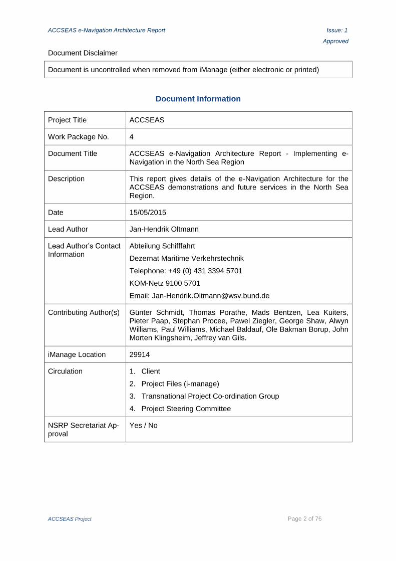
Document Information
Project Title ACCSEAS
Work Package No. 4
Document Title ACCSEAS e-Navigation Architecture Report - Implementing e-Navigation in the North Sea Region
Description This report gives details of the e-Navigation Architecture for the ACCSEAS demonstrations and future services in the North Sea Region.
Date 15/05/2015
Lead Author Jan-Hendrik Oltmann
Lead Author’s Contact Information
Abteilung Schifffahrt
Dezernat Maritime Verkehrstechnik
Telephone: +49 (0) 431 3394 5701
KOM-Netz 9100 5701
Email: [email protected]
Contributing Author(s) Günter Schmidt, Thomas Porathe, Mads Bentzen, Lea Kuiters, Pieter Paap, Stephan Procee, Pawel Ziegler, George Shaw, Alwyn Williams, Paul Williams, Michael Baldauf, Ole Bakman Borup, John Morten Klingsheim, Jeffrey van Gils.
iManage Location 29914
Circulation 1. Client
2. Project Files (i-manage)
3. Transnational Project Co-ordination Group
4. Project Steering Committee
NSRP Secretariat Ap-proval
Yes / No

ACCSEAS e-Navigation Architecture Report Issue: 1
Approved
ACCSEAS Project Page 3 of 76
Executive Summary This Report describes the ACCSEAS e-Navigation architecture for the North Sea Region (NSR) and beyond. The term ‘architecture’ is used in the same way as within system theory (as opposed to architecture proper or civil engineering proper) as follows:
‘A system architecture (…) is the conceptual model that defines the structure, behaviour, and more views of a system. An architecture description is a formal description and repre-sentation of a system, organized in a way that supports reasoning about the structures and behaviours of the system. A system architecture can comprise system components, the ex-ternally visible properties of those components, the relationships (e.g. the behaviour) be-tween them. It can provide a plan from which products can be procured, and systems devel-oped, that will work together to implement the overall system. (…) One can think of system architecture as a set of representations of an existing (or future) system. It conveys the in-formational content of the elements comprising a system, the relationships among those el-ements, and the rules governing those relationships. The architectural components and set of relationships between these components that an architecture description may consist of hardware, software, documentation, facilities, manual procedures, or roles played by organ-izations or people. A system architecture primarily concentrates on the internal interfaces among the system's components or subsystems, and on the interface(s) between the system and its external environment, especially the user.’ (Wikipedia)
Accordingly, this Report firstly elaborates the ACCSEAS candidate solutions which were introduced in the ‘ACCSEAS Baseline & Priorities Report.’ It
analyses their operational and/or technical architectures;
harmonises these architectures with stipulations imported from the international domain:
- by addressing how candidate solutions fit into the IMO Secretary General’s proposed Sus-tainable Maritime Transportation System (SMTS) from an architectural point of view and
- by looking at their place within the IMO e-Navigation Strategy, namely within the IMO e-Navigation overarching architecture as contained in the IMO e-Navigation Strategy Imple-mentation Plan (SIP).
This process is called ‘mapping’: ‘Mapping’ means ‘showing how it is supportive’ to the different architectural perspectives at hand. Hence, when mapping candidate solutions to the different architectural perspectives, it is demonstrated not only that the candidate solutions have a place in those different architectural perspectives, but in what regards the candidate solutions support them;
assesses them from a strategic point of view in architectural terms.
Specifically, the following nine candidate solutions are investigated in this Report in detail in architectural terms:
Maritime Service Portfolios (MSPs)
Route Topology Model (RTM)
‘Maritime Cloud (MC)’ as an underlying technical framework solution
Innovative Architecture for Ship Positioning comprising both: a. Multi Source Positioning Service b. R-Mode at existing MF DGNSS and AIS Services
Maritime Safety Information/Notices to Mariners (MSI/NM) Service
Augmented Reality (AR) / Head-Up-Displays (HUDs)
Harmonized Data Exchange – Employing the Inter-VTS Exchange Format (IVEF)

ACCSEAS e-Navigation Architecture Report Issue: 1
Approved
ACCSEAS Project Page 4 of 76
Real Time Vessel Traffic Pattern Analysis and Warning Functionality for VTS
All 14 ACCSEAS candidate solutions are included in the mapping of ACCSEAS’ support for the IMO SG’s SMTS, however.
The analysis arrives at the following conclusions:
Architectural mapping is feasible
- with all candidate solutions investigated here;
- with the wide scope of qualities they exhibit individually;
- with the external stipulations imposed (e.g. from IMO e-Navigation) and the methods ap-plied,
- with a meaningful result each, i.e. at least one starting point for further operational and/or technical exploration and research or even NSR implementation suggestions in no un-precise terms.
This prove of feasibility in itself carries a two-fold success, namely:
- The generic e-Navigation target architectures, both for the shipboard and shore sides, are ‘working’ and therefore can be considered ‘correct’ to the extent of what they want to show at their respective levels of detail;
- Each candidate solutions investigated can be considered as ‘solid in architectural terms to the degree of detail investigated.’
There is a lasting wealth of ACCSEAS regarding the transformation of the international SMTS and e-Navigation strategies into their appropriate NSR implementations.
From an architectural perspective, some of the ACCSEAS candidate solutions are also demon-strated mature enough to be seriously considered for actual operational implementation in the near to intermediate future at least in the NSR as a legacy of ACCSEAS.
Other ACCSEAS candidate solutions require further analysis and exploration in due course.
Secondly, this Report addresses the place of the candidate solutions in regards to relevant pan-European initiatives. This in turn provides helpful insights for a future implementation of candidate solutions in the NSR, as being thereby now guided by the overarching internation-al as well as pan-European concepts and strategies.
This report finally introduces system engineering design techniques used to further develop the candidate solutions towards implementation as well as simulation architectures, thus preparing the discussion of these topics in the ‘ACCSEAS Training Needs Analysis Report’ and in the ‘ACCSEAS Use of Simulators in e-Navigation Training and Demonstration Re-port,’ as appropriate.
Regarding training needs, the architectural analysis seems to prompt certain training needs with the educational goal for the operational trainees to understand
- the operational processes holistically and in the required functional detail,
- the supporting technical processes, which are otherwise encapsulated or ‘invisible’ to opera-tors, still holistically, but only generally, however with their desired outcomes and delivera-bles as well as typical malfunction conditions in the required detail, again.

ACCSEAS e-Navigation Architecture Report Issue: 1
Approved
ACCSEAS Project Page 5 of 76
Contents
1 Introduction – Scope and content of this Report ............................................................. 7
1.1 Motivation and formal requirements ........................................................................ 7
1.2 Defining ‘architecture’ and ‘architectural terms’ ....................................................... 7
1.3 The context of this Report amongst other ACCSEAS reports and its scope ............ 8
2 ACCSEAS candidate solutions mapped to relevant international concepts (SMTS, e-Navigation) .......................................................................................................................... 11
2.1 The candidate solutions investigated in architectural terms ................................... 11
2.2 Candidate solutions and IMO SG’s Sustainable Maritime Transportation System (SMTS) ............................................................................................................................ 11
3 Candidate solutions and IMO’s overarching architecture for e-Navigation .................... 17
3.1 The international work on generic architecture at IMO and IALA ........................... 17
3.2 Mapping of the candidate solution Maritime Service Portfolios (MSPs) for the NSR (NSR-MSPs) .................................................................................................................... 21
3.2.1 Mapping to the overarching architecture ........................................................ 21
3.2.2 Mapping to the generic shipboard and shore architectures ............................ 22
3.2.3 Some considerations on the transnational MSPs Registry and its interaction with stakeholders and their systems ............................................................................. 25
3.3 Mapping of the candidate solution ‘Route Topology Model (RTM)’ ........................ 28
3.3.1 Mapping to the overarching architecture ........................................................ 28
3.3.2 Mapping to the generic shipboard and shore architectures ............................ 29
3.4 Mapping of the candidate solution ‘Maritime Cloud’ .............................................. 32
3.4.1 The technical entities of the MC introduced ................................................... 32
3.4.2 Mapping to the overarching architecture ........................................................ 34
3.4.3 Mapping to the generic shipboard and shore architectures ............................ 34
3.4.4 The functionality of ‘Application Interfaces (API)’ of MC Client Components .. 37
3.5 Mapping of the ‘Innovative Architecture for Ship Positioning’ ................................ 38
3.5.1 Joint mapping to the overarching architecture ................................................ 38
3.5.2 Mapping to the generic shipboard and shore architectures ............................ 39
3.6 Mapping of the candidate solution ‘Maritime Safety Information/Notices to Mariners (MSI/NM) Service’ ........................................................................................................... 43
3.6.1 Mapping to the overarching architecture ........................................................ 43
3.7 Mapping of the candidate solution ‘Augmented Reality / Head-Up-Displays (HUDs)’ 46
3.7.1 Mapping to the overarching architecture ........................................................ 46
3.7.2 Mapping to the generic shipboard architecture ............................................... 47
3.8 Mapping of the candidate solution ‘Harmonized Data Exchange – Employing the Inter-VTS Exchange Format (IVEF)’ ................................................................................ 49
ACCSEAS e-Navigation Architecture Report Issue: 1
Approved
ACCSEAS Project Page 6 of 76
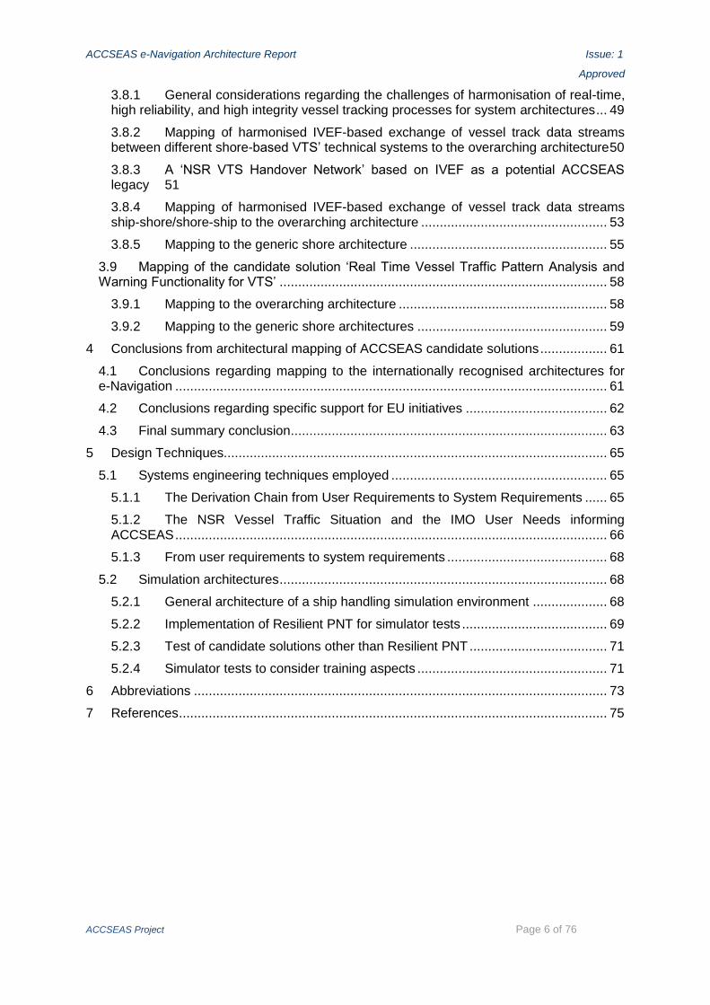
3.8.1 General considerations regarding the challenges of harmonisation of real-time, high reliability, and high integrity vessel tracking processes for system architectures ... 49
3.8.2 Mapping of harmonised IVEF-based exchange of vessel track data streams between different shore-based VTS’ technical systems to the overarching architecture 50
3.8.3 A ‘NSR VTS Handover Network’ based on IVEF as a potential ACCSEAS legacy 51
3.8.4 Mapping of harmonised IVEF-based exchange of vessel track data streams ship-shore/shore-ship to the overarching architecture .................................................. 53
3.8.5 Mapping to the generic shore architecture ..................................................... 55
3.9 Mapping of the candidate solution ‘Real Time Vessel Traffic Pattern Analysis and Warning Functionality for VTS’ ........................................................................................ 58
3.9.1 Mapping to the overarching architecture ........................................................ 58
3.9.2 Mapping to the generic shore architectures ................................................... 59
4 Conclusions from architectural mapping of ACCSEAS candidate solutions .................. 61
4.1 Conclusions regarding mapping to the internationally recognised architectures for e-Navigation .................................................................................................................... 61
4.2 Conclusions regarding specific support for EU initiatives ...................................... 62
4.3 Final summary conclusion ..................................................................................... 63
5 Design Techniques....................................................................................................... 65
5.1 Systems engineering techniques employed .......................................................... 65
5.1.1 The Derivation Chain from User Requirements to System Requirements ...... 65
5.1.2 The NSR Vessel Traffic Situation and the IMO User Needs informing ACCSEAS .................................................................................................................... 66
5.1.3 From user requirements to system requirements ........................................... 68
5.2 Simulation architectures ........................................................................................ 68
5.2.1 General architecture of a ship handling simulation environment .................... 68
5.2.2 Implementation of Resilient PNT for simulator tests ....................................... 69
5.2.3 Test of candidate solutions other than Resilient PNT ..................................... 71
5.2.4 Simulator tests to consider training aspects ................................................... 71
6 Abbreviations ............................................................................................................... 73
7 References ................................................................................................................... 75

ACCSEAS e-Navigation Architecture Report Issue: 1
Approved
ACCSEAS Project Page 7 of 76
1 Introduction – Scope and content of this Report
1.1 Motivation and formal requirements
This ‘ACCSEAS e-Navigation Architecture Report’ is a required deliverable of the ACCSEAS project as stipulated by the approved ACCSEAS ‘Application’ (ACCSEAS 2011), namely as a report from Work Package (WP) 4. The objectives for WP 4 were defined as:
‘e-Navigation Architecture & Standards - Develop a convergent overarching architecture and inform the development of standards for a NSR e-Navigation test-bed that will demonstrate ‘Proof-of-Concept’ of prototype e-Navigation services at key locations in the region which upgrade the region’s maritime accessibility and takes into account criteria for harmonisation and integration of e-Navigation between national service providers (Work Package 4)’ (AC-CSEAS 2011, para A4.2).
It is also stipulated that
‘beneficiaries use the findings of WP 3 to set out a proposed portfolio of e-Navigation ser-vices; based upon a novel architecture and associated new and improved standards. The WP will use design technique to provide an innovative e-Navigation architecture for the future provision of operational & technical services to improve maritime accessibility of the NSR. Activities from WP 4 will be used to inform EU and International development of standards via WP 2’ (ACCSEAS 2011, para A4.4.4).
It is further stipulated that this Report comprises the following sections:
‘Design of innovative e-Navigation architecture for ship/shore services’ from WP 4 Ac-tivity 6 – ‘Design of innovative e-Navigation architecture for ship/shore services and vir-tual realisation in simulation.’ This stipulation is fulfilled by the chapter ‘ACCSEAS candi-date solutions and IMO’s overarching e-Navigation Architecture.’
‘Innovative e-Navigation architecture for ship positioning’ from WP 4 Activity 5 – ‘De-sign of innovative e-Navigation architecture for ship positioning and virtual realisation in simulation.’ This stipulation is fulfilled by the description of the ACCSEAS candidate solu-tion ‘Innovative Architecture for Ship Positioning: Multi Source Positioning Service and R-Mode’ as described in the corresponding sections.
‘Design Techniques Section’ from WP 4 Activity 1 – ‘Harmonisation of architectural de-sign and simulation techniques, which can be applied to e-Navigation.’ This stipulation is fulfilled, due to the detailed nature of its desired content, namely addressing system en-gineering and simulation techniques specifically, in a dedicated chapter of this Report.
For ease of reading, the present ‘ACCSEAS e-Navigation Architecture Report’ will be abbre-viated in the following as the ‘Report’ (capitalised; other reports referenced will be in small letters).
1.2 Defining ‘architecture’ and ‘architectural terms’
This Report is supposed to describe the ACCSEAS e-Navigation architecture. In ACCSEAS, the term ‘architecture’ is used in the same way as within system theory (as opposed to archi-tecture proper or civil engineering proper) as follows:
‘A system architecture or systems architecture is the conceptual model that defines the structure, behavior, and more views of a system. An architecture description is a formal de-scription and representation of a system, organized in a way that supports reasoning about the structures and behaviors of the system. A system architecture can comprise system com-ponents, the externally visible properties of those components, the relationships (e.g. the

ACCSEAS e-Navigation Architecture Report Issue: 1
Approved
ACCSEAS Project Page 8 of 76
behavior) between them. It can provide a plan from which products can be procured, and systems developed, that will work together to implement the overall system. (…) One can think of system architecture as a set of representations of an existing (or future) system. It conveys the informational content of the elements comprising a system, the relationships among those elements, and the rules governing those relationships. The architectural com-ponents and set of relationships between these components that an architecture description may consist of hardware, software, documentation, facilities, manual procedures, or roles played by organizations or people. A system architecture primarily concentrates on the in-ternal interfaces among the system's components or subsystems, and on the interface(s) be-tween the system and its external environment, especially the user.’ (Wikipedia 2014; em-phasis added)
From the above definition and explanation it can be derived that several views or angles of perspective would be required to completely describe the ‘e-Navigation Architecture.’ Also, it follows, that they complement each other. This has an impact on the layout of this Report.
As the focus of ACCSEAS is on the North Sea Region (NSR), the geographical scope of this Report is the NSR. However, it is also expressively stated (ACCSEAS 2011, para 4.1), that influences external to the NSR should be taken into account, namely those from the interna-tional domain (IMO, ITU, IHO, IALA, to name a few) as well as from the pan-European do-main (EU initiatives and directives). Hence, any e-Navigation Architecture for the NSR would need to look for relevant international and pan-European conceptual imports; conversely, there is a requirement to identify potential feedback from the NSR to relevant international and pan-European bodies.
1.3 The context of this Report amongst other ACCSEAS reports and its scope
This Report is embedded into a context of several reports which is shown in this section.
This Report builds on the ‘ACCSEAS Baseline and Priorities Report (revised and updated Edition 3)’ (ACCSEAS 2015), abbreviated ‘B&P Report’ from now on, in particular
on the findings for the present and for the future (2020+) situation of shipping in the NSR taking into account the perceived impact of Marine Spatial Planning (MSP) in the NSR,
on the relevant pan-European and regional-European policies, initiatives and policies,
on the introduction to the international concepts of the Sustainable Maritime Transportation System (SMTS) and e-Navigation concept as well as on the presentation on how ACCSEAS sup-ports those international initiatives in general terms,
on the list and descriptions of candidate solutions which ACCSEAS offers and which were inves-tigated throughout the project, and
on the evaluation criteria for the above candidate solutions.
This Report then firstly elaborates the candidate solutions in Chapters 2 as follows:
analysis their operational and/or technical architectures – This is the Architectural or Ontological Analysis (compare ‘B&P Report’ for introduction);
harmonises these architectures with the e-Navigation architecture stipulations imported from the international domain, i.e. this finalises the discussion begun in the ‘B&P Report’ – here on the level of the specific candidate solutions; and
assesses them from a strategic point of view in architectural terms.

ACCSEAS e-Navigation Architecture Report Issue: 1
Approved
ACCSEAS Project Page 9 of 76
Therefore, the scope of this Report does explain the context and how a candidate solution fits into the context of the NSR and of the e-Navigation architecture stipulations. However, this Report does not elaborate any candidate solution to the detail level needed for opera-tional and/or technical implementation. I.e. this Report remains on the level of individual sys-tems, services and tools as ‘black boxes’ identified, and it does therefore not show the ‘how’ to implement a candidate solution in precise engineering terms, i.e. it does not provide ‘blue prints’ for the systems, services, and tools under consideration. This is the scope of further reports and documents (compare Figure 1-1).
ACCSEAS Baseline and Priorities Report
ACCSEAS e-Navigation Architecture Report
ACCSEAS Training Needs Analysis Report
ACCSEAS NSR GIS database
North Sea Region Route Topology Model Description
Multi-Source Positioning Sensor Service Description
Other Service Descriptions
ACCSEAS Use of Simulators in e-Navigation Training and Demonstration Report
R-Mode Feasibility Study Milestone Reports 1-5
ACCSEAS Final Report
A Plan for the Sustainability and Harmonisation of e -Navigation in the North Sea Region (e-Navigation Sustainability Plan)
Transferable Best Practice Guide
Demonstrators at ACCSEAS Test Bed
Figure 1-1: Context of ACCSEAS documents (as stipulated by (ACCSEAS 2011), as updated during project)
This report secondly introduces system engineering design techniques used to further de-velop the candidate solutions towards implementation (Chapter 5.1) as well as simulation architectures (Chapter 5.2), thus preparing the discussion of these topics in the ‘ACCSEAS Training Needs Analysis Report’ and in the ‘ACCSEAS Use of Simulators in e-Navigation Training and Demonstration Report,’ as appropriate.
In addition, some even more specific architectural aspects are referenced in corresponding ACCSEAS documents.

ACCSEAS e-Navigation Architecture Report Issue: 1
Approved
ACCSEAS Project Page 10 of 76
This page is deliberately blank.

ACCSEAS e-Navigation Architecture Report Issue: 1
Approved
ACCSEAS Project Page 11 of 76
2 ACCSEAS candidate solutions mapped to relevant international concepts (SMTS, e-Navigation)
Starting with this chapter, the Architectural or Ontological Analysis, as introduced in the ‘B&P Report,’ will be conducted on the specific level of the candidate solutions. This will be done
firstly by addressing how candidate solutions fit into the IMO Secretary General (SG)’s proposed SMTS (IMO-SG 2013) from an architectural point of view (in this chapter) and
secondly by looking at their place within the IMO e-Navigation Strategy (IMO 2009; IMO 2014), namely within the IMO e-Navigation overarching architecture as contained in the IMO e-Navigation Strategy Implementation Plan (SIP) (IMO 2014) (in Chapter 3).
Chapter 4 then addresses the place of the candidate solutions in regards to relevant pan-European initiatives, again stressing architectural terms. This in turn will provide helpful in-sights for a future implementation of candidate solutions in the NSR, as being thereby then guided by the overarching international as well as pan-European concepts and strategies.
2.1 The candidate solutions investigated in architectural terms
Out of the total of 14 ACCSEAS candidate solutions identified in the ‘B&P Report’ the follow-ing nine ACCSEAS candidate solutions are investigated in architectural terms in this Re-port:1
Maritime Service Portfolios (MSPs) for the NSR (NSR-MSPs)
Route Topology Model (RTM)
‘Maritime Cloud (MC)’ as an underlying technical framework solution
Innovative Architecture for Ship Positioning comprising both: c. Multi Source Positioning Service d. R-Mode at existing MF DGNSS and AIS Services
Maritime Safety Information/Notices to Mariners (MSI/NM) Service
Augmented Reality (AR) / Head-Up-Displays (HUDs)
Harmonized Data Exchange – Employing the Inter-VTS Exchange Format (IVEF)
Real Time Vessel Traffic Pattern Analysis and Warning Functionality for VTS
All 14 ACCSEAS candidate solutions were included in the following mapping of ACCSEAS’ support for the IMO SG’s SMTS, however.
2.2 Candidate solutions and IMO SG’s Sustainable Maritime Transportation System (SMTS)
The IMO SG’s SMTS was introduced in the ‘B&P Report,’ and general architectural contents and implications were identified. In particular, a high level architectural description in the format of a structured graphical representation of the Maritime Transportation System and its stakeholders in conjunction with a textual description in table format were given.
Here, it is discussed how the candidate solutions may support the SMTS from within the NSR. Mapping the ACCSEAS specific activities, in particular the candidate solutions, to the SMTS’s relevant statements renders Table 1.2
1 That not all 14 candidate solutions were investigated nor to the same degree of detail, is solely due to ACCSEAS project resource limitations; there were no other reasons.
2 Note: ACCSEAS partnership largely consists of administrations, i.e. the subsidiary organisa-tions for ‘Governments’ as IMO’s Partners, from all countries around the NSR (except Belgium);
ACCSEAS e-Navigation Architecture Report Issue: 1
Approved
ACCSEAS Project Page 12 of 76
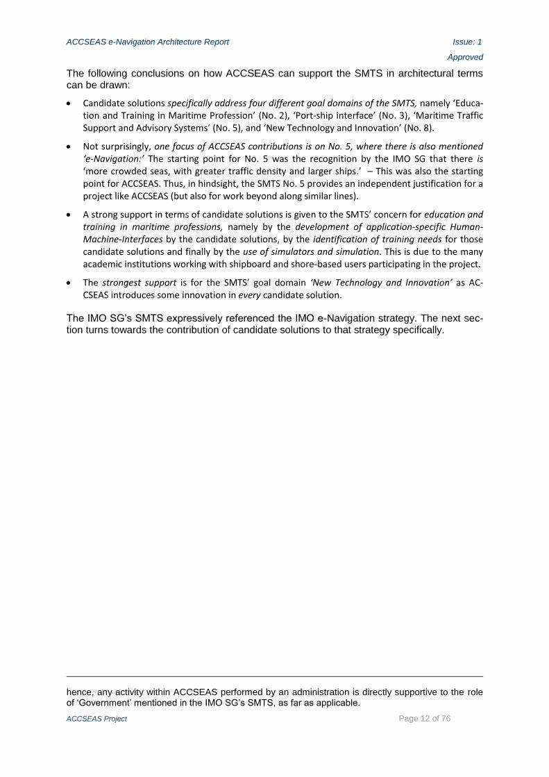
The following conclusions on how ACCSEAS can support the SMTS in architectural terms can be drawn:
Candidate solutions specifically address four different goal domains of the SMTS, namely ‘Educa-tion and Training in Maritime Profession’ (No. 2), ‘Port-ship interface’ (No. 3), ‘Maritime Traffic Support and Advisory Systems’ (No. 5), and ‘New Technology and Innovation’ (No. 8).
Not surprisingly, one focus of ACCSEAS contributions is on No. 5, where there is also mentioned ‘e-Navigation:’ The starting point for No. 5 was the recognition by the IMO SG that there is ‘more crowded seas, with greater traffic density and larger ships.’ – This was also the starting point for ACCSEAS. Thus, in hindsight, the SMTS No. 5 provides an independent justification for a project like ACCSEAS (but also for work beyond along similar lines).
A strong support in terms of candidate solutions is given to the SMTS’ concern for education and training in maritime professions, namely by the development of application-specific Human-Machine-Interfaces by the candidate solutions, by the identification of training needs for those candidate solutions and finally by the use of simulators and simulation. This is due to the many academic institutions working with shipboard and shore-based users participating in the project.
The strongest support is for the SMTS’ goal domain ‘New Technology and Innovation’ as AC-CSEAS introduces some innovation in every candidate solution.
The IMO SG’s SMTS expressively referenced the IMO e-Navigation strategy. The next sec-tion turns towards the contribution of candidate solutions to that strategy specifically.
hence, any activity within ACCSEAS performed by an administration is directly supportive to the role of ‘Government’ mentioned in the IMO SG’s SMTS, as far as applicable.
ACCSEAS e-Navigation Architecture Report Issue: 1
Approved
ACCSEAS Project Page 13 of 76
Specific Actions/Activities in support of the transition towards an SMTS
(IMO-SG 2013, Annex)
Direct ACCSEAS contribution in terms of …
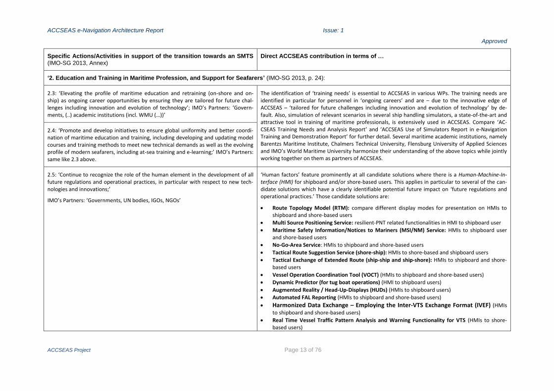
‘2. Education and Training in Maritime Profession, and Support for Seafarers’ (IMO-SG 2013, p. 24):
2.3: ‘Elevating the profile of maritime education and retraining (on-shore and on-ship) as ongoing career opportunities by ensuring they are tailored for future chal-lenges including innovation and evolution of technology’; IMO’s Partners: ‘Govern-ments, (..) academic institutions (incl. WMU (…))’
The identification of ‘training needs’ is essential to ACCSEAS in various WPs. The training needs are identified in particular for personnel in ‘ongoing careers’ and are – due to the innovative edge of ACCSEAS – ‘tailored for future challenges including innovation and evolution of technology’ by de-fault. Also, simulation of relevant scenarios in several ship handling simulators, a state-of-the-art and attractive tool in training of maritime professionals, is extensively used in ACCSEAS. Compare ‘AC-CSEAS Training Needs and Analysis Report’ and ‘ACCSEAS Use of Simulators Report in e-Navigation Training and Demonstration Report’ for further detail. Several maritime academic institutions, namely Barentzs Maritime Institute, Chalmers Technical University, Flensburg University of Applied Sciences and IMO’s World Maritime University harmonize their understanding of the above topics while jointly working together on them as partners of ACCSEAS.
2.4: ‘Promote and develop initiatives to ensure global uniformity and better coordi-nation of maritime education and training, including developing and updating model courses and training methods to meet new technical demands as well as the evolving profile of modern seafarers, including at-sea training and e-learning;’ IMO’s Partners: same like 2.3 above.
2.5: ‘Continue to recognize the role of the human element in the development of all future regulations and operational practices, in particular with respect to new tech-nologies and innovations;’
IMO’s Partners: ‘Governments, UN bodies, IGOs, NGOs’
‘Human factors’ feature prominently at all candidate solutions where there is a Human-Machine-In-terface (HMI) for shipboard and/or shore-based users. This applies in particular to several of the can-didate solutions which have a clearly identifiable potential future impact on ‘future regulations and operational practices.’ Those candidate solutions are:
Route Topology Model (RTM): compare different display modes for presentation on HMIs to shipboard and shore-based users
Multi Source Positioning Service: resilient-PNT related functionalities in HMI to shipboard user
Maritime Safety Information/Notices to Mariners (MSI/NM) Service: HMIs to shipboard user and shore-based users
No-Go-Area Service: HMIs to shipboard and shore-based users
Tactical Route Suggestion Service (shore-ship): HMIs to shore-based and shipboard users
Tactical Exchange of Extended Route (ship-ship and ship-shore): HMIs to shipboard and shore-based users
Vessel Operation Coordination Tool (VOCT) (HMIs to shipboard and shore-based users)
Dynamic Predictor (for tug boat operations) (HMI to shipboard users)
Augmented Reality / Head-Up-Displays (HUDs) (HMIs to shipboard users)
Automated FAL Reporting (HMIs to shipboard and shore-based users)
Harmonized Data Exchange – Employing the Inter-VTS Exchange Format (IVEF) (HMIs to shipboard and shore-based users)
Real Time Vessel Traffic Pattern Analysis and Warning Functionality for VTS (HMIs to shore-based users)

ACCSEAS e-Navigation Architecture Report Issue: 1
Approved
ACCSEAS Project Page 14 of 76
The operational presentation surfaces developed are also extensively reviewed by respective profes-sionals in simulation sessions and workshops engaging with the proposed HMIs.
‘3. Energy Efficiency and Port-ship Interface’ (IMO-SG 2013, p. 25):
3.3: ’Promote the use of standardized single-window electronic systems;’ IMO’s Partners: ‘Governments, IGOs (…), industry’
The candidate solution Automated FAL Reporting addresses electronic means for ship reporting in accordance with the IMO FAL Convention, which embraces the notion of ‘single-window.’
‘5. Maritime Traffic Support and Advisory Systems’ (IMO-SG 2013, p. 27):
5.2: ‘Showcase lessons learned from maritime traffic support systems including expe-riences from VTS areas’;
IMO’s Partners: ‘Governments, industry, seafarer’s representatives, NGO (including IALA).’
The following candidate solutions are ‘supportive to maritime traffic’ or to ‘maritime traffic support systems’ (in a strict sense). Their findings (‘lessons learned’) will be made publicly available in the appropriate ACCSEAS report (i.e. ‘showcased’):
Maritime Service Portfolios (MSPs) for the NSR (NSR-MSPs): Once fully developed, they will provide the knowledge, eventually in electronic format, on the variety of operational and tech-nical services, together with their respective service features and quality levels to be expected by shipping, in a given area – here: the NSR. The knowledge of available services along the fairways in the NSR, acquired in an efficient manner, will influence maritime traffic to a degree yet un-known. Individual services, including those which are further considered in ACCSEAS as candidate solutions, will be referenced by the MSPs; therefore, the degree to which MSPs influence the maritime traffic depends on the degree of influence of the individual service’s referenced by the MPSs but may be larger than the sum of those individual impacts due to the inherent synergies of the MSPs concept.
The Route Topology Model (RTM), potentially even internationally standardized, provides a theoretical model potentially underlying any and all future traffic support systems as it describes the available routes (including their features and their connectivity) the maritime traffic can po-tentially use in a given maritime traffic situation.
Maritime Safety Information/Notices to Mariners (MSI/NM) Service and No-Go-Area Service: The maritime traffic may be directly influenced by maritime safety information sent to all vessels and No-Go-Area information sent to participating individual vessels.
The Tactical Route Suggestion Service (shore-ship) directly (‘tactically’) influences the
maritime traffic (participating vessels and surrounding vessels) by route suggestions.
The Vessel Operation Coordination Tool (VOCT) directly influences the operation of the vessels participating in the SAR operation at hand which in turn influences the surrounding vessel traffic.
The Harmonized Data Exchange – Employing the Inter-VTS Exchange Format (IVEF) directly supports real-time VTS-to-VTS vessel track data stream exchange, amongst other functions, and also support of shipping by potentially providing VTS-acquired vessel traffic footage.
The Real Time Vessel Traffic Pattern Analysis and Warning Functionality for VTS automatically

ACCSEAS e-Navigation Architecture Report Issue: 1
Approved
ACCSEAS Project Page 15 of 76
alerts a VTS centre to behaviour of individual ship(s) not matching the general flow of traffic in that area. If necessary, the VTS centre would be in a position to influence the vessel traffic ac-cordingly.
The ACCSEAS Test Bed in the south-western part of the NSR comprises several VTS service areas, and VTS related experiences from the ACCSEAS Test Bed will be presented in the appropriate report.
5.3: ‘Showcase and promote the use of up-to-date hydrographic, meteorological and environmental data as tools for route optimisation;’
IMO’s Partners: ‘Governments, IGOs (including IHO, WMO), NGOs, industry (including data and equipment providers).’
The candidate solutions Maritime Safety Information/Notices to Mariners (MSI/NM) and No-Go-Area Services as well as the Vessel Operation Coordination Tool (VOCT) are points in case.
5.4: ‘Support continued standardization of aids to navigation and operation of on-board navigation equipment, including optimisation of ECDIS use with further sources of data;’
IMO’s Partners: ‘Governments, industry, IGOs (including IHO), NGOs (including IALA).’
It is the expressive intent of ACCSEAS to derive contributions to European and international standardi-sation from those candidate solutions which were developed to an appropriate degree of maturity during the project’s duration. This applies to candidate solutions which affect both the shore-side (‘aids-to-navigation’) and the shipboard side (‘on-board navigation equipment’). Specific contributions to standardisation will be a standing topic throughout this Report.
‘8. New Technology and Innovation’ (IMO-SG 2013, p. 30):
8.1: ‘Showcasing new technology and innovation, development of appropriate global standards and approval procedures;’
IMO’ Partners: ‘Governments, IGOs, NGOs (including IALA, IACS and ISO), industry (including shipbuilders and manufacturers)
All candidate solutions are inherently innovative. Some use and demonstrate existing technology for new fields of application and/or in a novel way, other are developments of new methods and/or new technologies and are therefore innovations with a degree of scientific research involved, as follows:
Maritime Service Portfolios (MSPs) for the NSR: The concept of ‘service portfolio management’ within the context of ‘service strategy’ which is well-established at the IT domain (compare e.g. ITIL V3 (Office of Government Commerce 2007)) is adapted to the maritime domain.
Route Topology Model (RTM) applies existing maritime concepts like legs and nodes (waypoints, ports, junctions etc.) in the context of the mathematical graph theory to gain new potentials for traffic management.
‘Maritime Cloud’ as an underlying technical framework solution applies existing methods for optimizing telecommunications from the IT domain to the maritime domain on a global scale, thus postulating entities novel to the maritime domain, while using existing technologies for the maritime telecommunication as such;
Innovative Architecture for Ship Positioning: Multi Source Positioning Service employs
existing satellite and existing as well as novel terrestrial radio navigation systems for a novel and improved method for shipboard position fix in combination with an innovative HMI;
Innovative Architecture for Ship Positioning: R-Mode at existing MF DGNSS and AIS Ser-
vices applies the well understood Signal-of-Opportunity concept of radio navigation to existing, globally distributed maritime systems in order to arrive at a novel terrestrial radio navigation sys-
8.2. ‘Encourage development of new technology and innovation to meet future needs for the Maritime Transportation System;’
IMO’s Partners: same as 8.1
8.4. ‘Encourage scientific research and development activities and incorporate results into activities of IMO’
IMO’s Partners: ‘IMO, Governments, NGOs, industry, seafarer’s representatives, classification societies’

ACCSEAS e-Navigation Architecture Report Issue: 1
Approved
ACCSEAS Project Page 16 of 76
tem;
Maritime Safety Information/Notices to Mariners (MSI/NM), No-Go-Area Services, Vessel Operation Coordination Tool (VOCT) as well as Automated FAL Reporting employ existing tele-communication technologies in well understood fields of application (i.e. MSI/NM distribution, under keel clearance advice, SAR operations, and vessel port clearance) in a novel way, i.e. by an optimal communication path selection (MC concept) in combination with an innovative HMI;
Tactical Route Suggestion Service (shore-ship) and Tactical Exchange of Intended Route (ship-ship and ship-shore) employ existing telecommunications technologies for a new
field of application (i.e. tactical route data exchange) and in a novel way, i.e. by an optimal com-munication path selection (MC concept) in combination with an innovative HMI;
Augmented Reality / Head-Up-Displays (HUDs) makes available known information/data items of maritime entities as seen from a vessel’s bridge on a vessel’s existing or novel HMI devices in a novel way;
Dynamic Predictor (for tug boat operations): The dynamic prediction of own vessel’s move-ments is transferred to the specifics of tug boat dynamic and operation in combination with an innovative HMI;
Harmonized Data Exchange – Employing the Inter-VTS Exchange Format (IVEF) uses an existing IALA standard for real-time vessel track data exchange with existing communication technologies to add a new degree of real-time connectivity;
Real Time Vessel Traffic Pattern Analysis and Warning Functionality for VTS uses existing data for a novel dimension of decision support at a VTS centre.
8.6. ‘Promote partnership between academic and/or research institutions and the maritime industry for targeted results’
IMO’s Partners: ‘Industry, academic/research institutions’
The very composition of the ACCSEAS partnership is a point in case. In addition, several spin-offs with information/knowledge transfer to industry/manufacturers, are generated by administration AC-CSEAS partners when commissioning contributions to their envisaged candidate solutions.
Table 1: Mapping of ACCSEAS features and candidate solutions to the SMTS’ Actions

ACCSEAS e-Navigation Architecture Report Issue: 1
Approved
ACCSEAS Project Page 17 of 76
3 Candidate solutions and IMO’s overarching architecture for e-Navigation
It is now necessary to turn to the more technical architecture definitions. This chapter there-fore reflects on the IMO defined ‘overarching architecture’ for e-Navigation. The goal of this chapter is to show where and how the NSR e-Navigation architecture would fit into the over-arching architecture.3 Thereby, the support of the ACCSEAS candidate solutions for the IMO SIP (IMO 2014), including the identified ‘Solutions,’ ‘Sub-Solutions,’ and ‘Tasks’ contained therein, is identified and presented in no un-precise terms, since all these ‘Solutions,’ ‘Sub-Solutions,’ and ‘Tasks’ can be themselves similarly referenced back or ‘mapped’ to the over-arching architecture in no un-precise terms. Potentially, some of the following mappings of the ACCSEAS candidate solutions may be even identical to any such mapping of ‘Solutions,’ ‘Sub-Solutions,’ and ‘Task’ fulfilments, at least in some cases, thus rendering a directly ap-plicable architectural mapping.
3.1 The international work on generic architecture at IMO and IALA
Figure 3-1 shows the IMO adopted overarching architecture (IMO 2014, para 28). It shows in particular the interdependency of the different major architectural elements.
Figure 3-1: IMO adopted overarching architecture for e-Navigation (IMO 2014, Figure 1 in para 28)
In Figure 3-1, certain details are deliberately encapsulated in ‘black box’ fashion in order to demonstrate how the major entities connect and cooperate, hence ‘overarching.’ Such enti-ties depicted in ‘black box’ fashion in Figure 3-1 are in particular:
3 Note that this chapter fulfills the stipulation of the ACCSEAS Application to include a section on ‘Design of innovative e-Navigation architecture for ship/shore services’ in this Report. The innova-tive nature of the candidate solutions was demonstrated already in the previous chapter by mapping them to the SMTS’ goal domain ‘New Technology and Innovation’ (see Table 1).

ACCSEAS e-Navigation Architecture Report Issue: 1
Approved
ACCSEAS Project Page 18 of 76
‘Shipboard user’ and ‘Shore-based user:’ These are iconic depictions for those user groups. IMO has identified a plurality of each (IMO 2009, Annex 2), and the IMO lists show the complexity of the user domain in regards to the stakeholder groups they represent. But not only the variety of both shipboard and shore-based users is encapsulated in the iconic depiction: This is true also for all aspects related to the day-to-day-life of those professionals, including e.g. education and training, to start with. Some ACCSEAS reports deal expressively with certain ‘human factors,’ and it will be therefore necessary to zoom in on those facets accordingly.
‘Operational services:’ Clearly, there is a wealth of operational services running between shore and ship, both existing and novel ones; their connectivities and their interdependencies are en-capsulated in the one term ‘operational services’ with the iconic depiction of the shipboard user and with the iconic depiction of the shore-based user as terminal points between which the op-erational services take place. Operational services are provided from ashore or shore-based. Some of the candidate solutions address or at least affect specific operational services.
‘Technical services:’ Similarly there is a wealth of technical services employed to support the above operational services, both existing and novel ones; again, their connectivities and interde-pendencies are encapsulated. However, the architectural distinction between ‘functional links’ and ‘physical links’ was recognized, indicated by two iconic arrows for the technical services. Some of the candidate solutions address specific technical services.
‘Maritime Service Portfolios (MSPs):’ This simple vertical line encapsulates the above connectiv-ities and interdependencies not only of the operational services and of the technical services among themselves, but also the hierarchical client-server-relationships between ‘requesting ser-vices’ and ‘requested services’ (in any meaningful combination of operational and technical ser-vices). The exploration of the MSPs internal structure is the subject of a candidate solution.
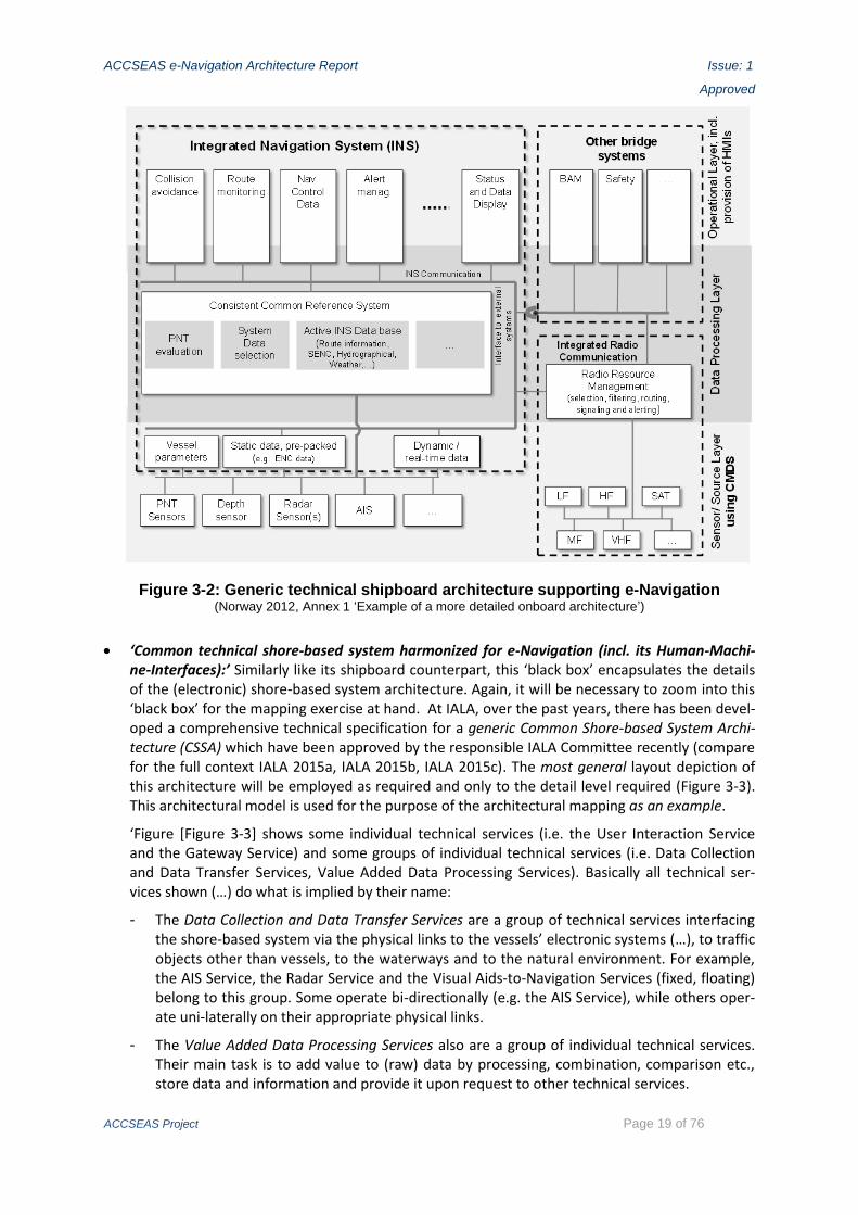
‘Shipboard technical equipment supporting e-Navigation (incl. its Human-Machine-Interfaces):’ This ‘black box’ encapsulates the details of the shipboard electronic architecture. It will be nec-essary to zoom into this ‘black box’ for the mapping exercise at hand. To assist in that, a generic architecture which is based on IMO recognized shipboard technical equipment in the context of the preparation of the SIP will be employed as required and only to the detail level required (compare Figure 3-2). Some candidate solutions solely deal with specifics of the HMI between the shipboard technical equipment and the mariner. Some candidate solutions will have a bear-ing on the shipboard equipment. Which in turn implies that some of the existing functional re-quirement descriptions, e.g. IMO performance standards and IEC test standards, may need to be amended in the future to achieve the desired effects demonstrated by ACCSEAS.
ACCSEAS e-Navigation Architecture Report Issue: 1
Approved
ACCSEAS Project Page 19 of 76
Figure 3-2: Generic technical shipboard architecture supporting e-Navigation (Norway 2012, Annex 1 ‘Example of a more detailed onboard architecture’)
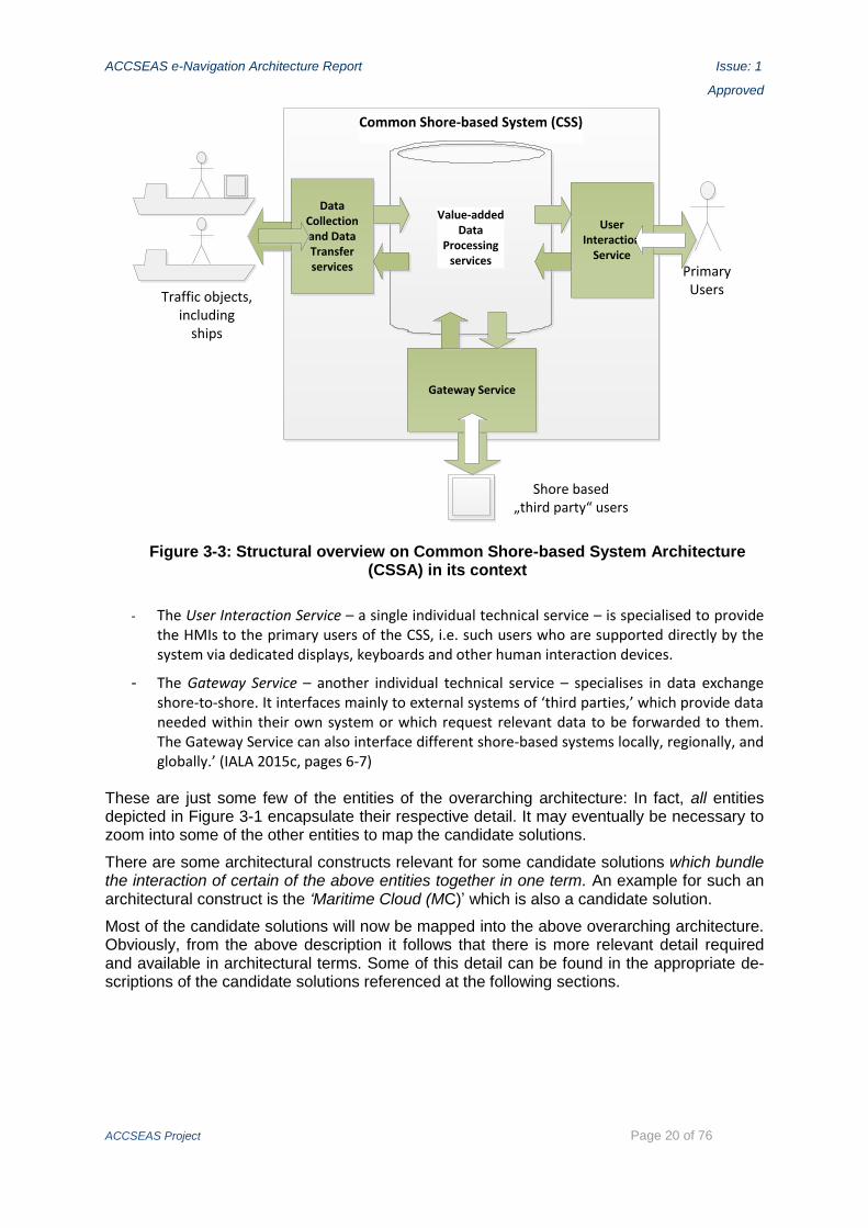
‘Common technical shore-based system harmonized for e-Navigation (incl. its Human-Machi-ne-Interfaces):’ Similarly like its shipboard counterpart, this ‘black box’ encapsulates the details of the (electronic) shore-based system architecture. Again, it will be necessary to zoom into this ‘black box’ for the mapping exercise at hand. At IALA, over the past years, there has been devel-oped a comprehensive technical specification for a generic Common Shore-based System Archi-tecture (CSSA) which have been approved by the responsible IALA Committee recently (compare for the full context IALA 2015a, IALA 2015b, IALA 2015c). The most general layout depiction of this architecture will be employed as required and only to the detail level required (Figure 3-3). This architectural model is used for the purpose of the architectural mapping as an example.
‘Figure [Figure 3-3] shows some individual technical services (i.e. the User Interaction Service and the Gateway Service) and some groups of individual technical services (i.e. Data Collection and Data Transfer Services, Value Added Data Processing Services). Basically all technical ser-vices shown (…) do what is implied by their name:
- The Data Collection and Data Transfer Services are a group of technical services interfacing the shore-based system via the physical links to the vessels’ electronic systems (…), to traffic objects other than vessels, to the waterways and to the natural environment. For example, the AIS Service, the Radar Service and the Visual Aids-to-Navigation Services (fixed, floating) belong to this group. Some operate bi-directionally (e.g. the AIS Service), while others oper-ate uni-laterally on their appropriate physical links.
- The Value Added Data Processing Services also are a group of individual technical services. Their main task is to add value to (raw) data by processing, combination, comparison etc., store data and information and provide it upon request to other technical services.
ACCSEAS e-Navigation Architecture Report Issue: 1
Approved
ACCSEAS Project Page 20 of 76
Common Shore-based System (CSS)
Value-addedData
Processingservices
PrimaryUsersTraffic objects,
including ships
Shore based„third party“ users
Data Collection and Data Transfer services
UserInteraction
Service
Gateway Service
Figure 3-3: Structural overview on Common Shore-based System Architecture (CSSA) in its context
- The User Interaction Service – a single individual technical service – is specialised to provide the HMIs to the primary users of the CSS, i.e. such users who are supported directly by the system via dedicated displays, keyboards and other human interaction devices.
- The Gateway Service – another individual technical service – specialises in data exchange shore-to-shore. It interfaces mainly to external systems of ‘third parties,’ which provide data needed within their own system or which request relevant data to be forwarded to them. The Gateway Service can also interface different shore-based systems locally, regionally, and globally.’ (IALA 2015c, pages 6-7)
These are just some few of the entities of the overarching architecture: In fact, all entities depicted in Figure 3-1 encapsulate their respective detail. It may eventually be necessary to zoom into some of the other entities to map the candidate solutions.
There are some architectural constructs relevant for some candidate solutions which bundle the interaction of certain of the above entities together in one term. An example for such an architectural construct is the ‘Maritime Cloud (MC)’ which is also a candidate solution.
Most of the candidate solutions will now be mapped into the above overarching architecture. Obviously, from the above description it follows that there is more relevant detail required and available in architectural terms. Some of this detail can be found in the appropriate de-scriptions of the candidate solutions referenced at the following sections.

ACCSEAS e-Navigation Architecture Report Issue: 1
Approved
ACCSEAS Project Page 21 of 76
3.2 Mapping of the candidate solution Maritime Service Portfolios (MSPs) for the NSR (NSR-MSPs)
3.2.1 Mapping to the overarching architecture
The mapping of the candidate solution Maritime Service Portfolios (MSPs) for the NSR (NSR-MSPs) into the overarching architecture is directly possible because the NSR-MSPs is a subset of the global future MSPs which is to be eventually defined in any relevant detail by IMO by means of an envisaged IMO Resolution on Maritime Service Portfolios (MSPs) (IMO 2014, Task 17).
Shipboard environment Shore-based authority / stakeholder
Shipboard userShore-based user
(such as VTS operator etc.)
Shore-based
system
of different
stakeholder
Shore-based
system
of different
stakeholder
Ship-side Links Shore-Side
Info
rma
tio
n D
om
ain
Da
ta D
om
ain
Common technical
shore-based system
harmonized for e-Navigation(incl. its Human-Machine-Interfaces)
Shipboard technical
equipment supporting
e-Navigation(incl. its Human-Machine-Interfaces)
Data provided in
required format
Stated information
needs/
information items
requested
Data provided in
required format
Stated information needs /
information items
requested
Operational
services
Stated data
request
Data provided in
required format
Data provided
in required
format
Stated data
request
Machine-to-Machine-
Interfaces
Human-Machine-
Interface(s)
Human-Machine-
Interface(s)
World Wide Radionavigation System (WWRNS) of IMO (incl. GNSS, GNSS augmentation and terrestrial backup)
„common data structure“ =
proposed Common Maritime
Data Structure (CMDS)
Functional links
used by
Technical services
Physical links
used by
Technical services
(NSR-)Maritime Service
Portfolios (MSPs)
Note: There are operational and technical interactions between different shipboard environments. These are not shown for simplicity’s sake in this figure.
Transnational
Maritime Service
Portfolios
Registry
Figure 3-4: Mapping of the NSR-MSPs to the overarching architecture
Figure 3-4 shows the MSPs highlighted (in dark red). Since the MSPs are, from an architec-tural point of view, purposeful bundles of services, both operational and/or technical, the services and the associated information requests associated with the MSPs are also high-lighted (in light red): In a general and simplistic sense the operational services are request-ing the technical services.
All technical services deliver the technical functionalities as requested, using their specific means, e.g. their functional and physical links to the vessels as shown in the picture.
Also note that for simplicity’s sake the client-server-relationships amongst different opera-tional services and amongst different technical services are not shown here. The latter will come to the fore when considering further candidate solutions.
The field of the MSPs is presently internationally only defined at its highest level (IMO 2014, paras 17ff+Annex 2). This level of representation does not directly support the system de-sign of those systems supporting the respective MSPs. In order to arrive at a (nearly) com-plete and also transparent derivation chain of client-server-relationships, i.e. requirements and fulfillment functionality descriptions between the different services within the MSPs, thus

ACCSEAS e-Navigation Architecture Report Issue: 1
Approved
ACCSEAS Project Page 22 of 76
constituting the internal structure of the MSPs, more work is required beyond what could be achieved within ACCSEAS. This holds true even only for the NSR-MSPs. Obviously, the internal structure of the MSPs, encapsulated by the simple dotted line in Figure 3-4, exhibits a certain degree of complexity.
The organisations that provide services, e.g. by employing the CSS, are service providers. Therefore note, that the above considerations on the candidate solution NSR-MSPs provide the architectural constitution for the ACCSEAS proposed ‘NSR Service Provider Coordina-tion Group’ (compare ‘ACCSEAS e-Navigation Sustainability Plan’).
Note: The ‘Transnational Maritime Service Portfolio Registry’ will be discussed in the follow-ing sections when addressing the shore-side.
3.2.2 Mapping to the generic shipboard and shore architectures
An appropriate IT representation of the MSPs4 is indispensable to use the MSPs concept in any IT system, i.e. no IT-based functionality can be based on the above conventional defini-tions of MSPs directly. Rather, the MSPs need to be translated
into a MSPs related contribution to the Common Maritime Data Structure (CMDS), i.e. into a MSPs meta-level data model in accordance with IHO S-100 standards, as stipulated by IMO, and
into associated functionalities and algorithms of the technical entities dealing with this meta-level description correspondingly on the ship-board side and on the shore side.
Thus the MSPs functionalities would be mapped to corresponding functionalities of both the ‘shipboard technical equipment supporting e-Navigation’ as well as the CSS as follows:
To reside as a data model, on the shipboard side the apparently most appropriate place for the MSPs data model as such and as a whole would be in the ‘Data Processing Layer,’ namely in the ‘Active INS Data base’ (compare Figure 3-5).
Note, that this statement applies to the MSPs description as a whole, not to the mapping of indi-vidual services contained within the MSPs: Since the scope of the services bundled by the MSPs spans virtually all aspects of SOLAS-related shipboard technical functionality (and maybe even beyond SOLAS), technical equipment on all three layers would be affected to varying degree.
4 Note: For ease of reading, throughout this section only the acronym MSPs will be used in-stead of (NSR-)MSPs. It should be understood, however, that the statements apply both to the gener-ic MSPs definitions as well as to the NSR instance of the MSPs, namely the NSR-MSPs.

ACCSEAS e-Navigation Architecture Report Issue: 1
Approved
ACCSEAS Project Page 23 of 76
MSPs meta-level data on the MSPs as a whole kept here, including associated meta-level data on shore-provided services.
MSPs, …)
Shore-service
Provision Control (MSPs)
(working title)
Candidate functionality blocks for display of MSPs meta-level data, i.e. on the MSPs as a whole, at HMI entities
Figure 3-5: Mapping of the MSPs to the generic shipboard architecture
Regarding display of the MSPs as a whole for the shipboard side, this would be generated by the entities constituting and creating the HMIs for the mariner and would therefore be implemented on the ‘Operational Layer, including provision of HMIs’. There are some candidate functionality blocks of that layer for hosting the display of the MSPs as a whole eventually, namely
- the functional HMI entity ‘Route Monitoring’ because of the geospatial attachment of the MSPs as further explained in the following candidate solution RTM; or
- less fittingly but still possible, the functional HMI entity ‘Navigational Control Data’ because the MSPs are contributing to a new sense of navigational control, namely when navigation is relying on the shore-provision of particular services expressed in the MSPs; or
- an entirely new HMI entity called ‘Shore-service Provision Control (MSPs)’ (working title) that may eventually be created and defined as part of IMO’s INS concept because the MSPs as a whole may deem to be both thus important and sui generis (‘of own nature’).
Since this is of speculative nature at this point, in Figure 3-5 the highlight is given only in dotted lines.
Turning towards the exchange of MSPs descriptions, i.e. MSPs meta-level data, on the ship-board side the MSPs descriptions must be exchanged between onboard systems. Also, MSPs de-scriptions will certainly be received from ashore – compare name of ‘prioritized solution No. 9’ of the SIP: ‘Improved communication of VTS Service Portfolio.’ For that shore-ship MSPs data ex-change the functionalities of the ‘Integrated Radio Communication’ within the ‘Sensor/Source Layer using CMDS’ would be used (not highlighted in Figure 3-5) as further discussed at the can-didate solution ‘Maritime Cloud as a technical framework’ below.

ACCSEAS e-Navigation Architecture Report Issue: 1
Approved
ACCSEAS Project Page 24 of 76
On the shore side (compare Figure 3-6) the MSPs meta-level data model as a whole would reside in a technical service within in the group of the Value-added Data Processing services, in a dedi-cated Maritime Portfolio Registry Service (MPR).
This technical service would keep and maintain
- an own CSS’s copy of the MSPs master meta-level data model as harmonized by the compe-tent transnational body (international or pan-European or regional-European),
- an own CSS’s copy of any relevant MSPs meta-level data models of different relevant indi-vidual providers (e.g. in neighbouring countries or even in the same country),
- but may be in a position to amend that meta-level data in accordance with the own CSS’s service provision situation at run-time.
This technical service would deliver the relevant (NSR-)MSPs meta-level data
- to own CSS’s display as status information to those primary users supported directly by own CSS, e.g. at a VTS center, via the own User Interaction Service and/or
- to external shore-based system(s) via the Gateway Service, upon request and/or continuous-ly, and/or
- to vessels’ systems (see above) via appropriate Data Transfer services.

ACCSEAS e-Navigation Architecture Report Issue: 1
Approved
ACCSEAS Project Page 25 of 76
Common Shore-based System (CSS)
Value-added Data Processing services
PrimaryUsers
Traffic objects,including
ships
Transnational MSPs Registry – contains transnationally harmonised master meta-level definitions of services– operated and maintained by or on behalf of competent international or pan-European or regional-European body
Data Collection and Data Transfer services
UserInteraction Service
Gateway Service
Maritime Portfolio
Registry Service (MPR)
Display of status information on MSPs in area under consideration, including own CSS’s contribution.
Provider CSS’s copy of the MSPs data model as a whole resides here; run-time amendments by provider’s CSS to own MSPs part possible.
The MPR Service of own CSS would exchange MSPs meta-level data with ...
MPR Service of CSS of different provider (e.g. in
neighbouring country)
Figure 3-6: Mapping of the MSPs to the generic CSSA (Note: Interaction with ship systems not highlighted; compare ‘Maritime Cloud’ for this.)
The above own CSS’s offline copy of external MSPs meta-level data can be called ‘MSPs Registry Almanac.’ Hence, the MPR Service of a service providers contains and administers the own CSS’ MSPs Registry Almanac.
3.2.3 Some considerations on the transnational MSPs Registry and its interaction with stakeholders and their systems
3.2.3.1 Features of the MSPs Registry
The MSPs Registry is intended to facilitate the implementation of the MSPs concept as ex-plained above by providing a repository for the meta-level specification of operational and technical services and provisioned service instances, thereby making it a single reference point for provision and discovery of meta-level descriptions.

ACCSEAS e-Navigation Architecture Report Issue: 1
Approved
ACCSEAS Project Page 26 of 76
The MSPs Registry thus contains service specifications from a data modelling point of view according to an envisioned Maritime Service Specification Standard and provisioned service instances implemented according to a service specification.5, 6
The MSPs Registry aims at improving the visibility and accessibility of available maritime information and services. This enables service providers, consumers, and regulatory authori-ties to share a common view on service standards and provisioned services (Figure 3-7).
Figure 3-7: The different access roles of stakeholders to the MSPs Registry
As depicted in Figure 3-7, the MSPs Registry enables the ‘provider’ to ‘publish’ information related to its service instances so that the ‘consumer’ is able to ‘discover’ them and obtain everything (e.g. interface information) required to ultimately use those services.
The MSPs Registry supports some of the cornerstones of Service Oriented Architectures (SOA): Service loose coupling, abstraction, reusability, autonomy, composability, discovera-bility and standardized service contracts.
The MSPs Registry does not provide maritime information but a meta-level specification of services and the information/data they carry, and the technical means to obtain it. The MSPs Registry provides the mechanisms to manage the life cycle of meta-level service specifica-tions and service instances, from a data modelling point of view.
3.2.3.2 The need for a transnational MSPs Registry
The MSPs concept is an integral part of IMO’s e-Navigation strategy because it has the po-tential to massively contribute to the harmonisation which is the most fundamental goal of that strategy. To exploit that potential, a transnational MSPs Registry is required considering the pre-dominantly national scope of shore-based service providers today. Ideally, transna-tional would mean international, i.e. global, though, to achieve the maximum harmonisation.
Consequentially, IMO has asserted the role to govern the definition of the MSPs by taking ‘initial action’ (IMO 2014, Table 9). When this action will have been fulfilled, there will have been developed the concept of an International MSPs Registry, i.e. one globally visible
5 It should be noted that there are complementary points of view for service specification, for instance the physical implementation point of view, prompting life cycle management concepts such as ITIL V3 (Office of Government Commerce 2007). Those views need to and can be harmonized.
6 It is anticipated that an envisioned Maritime Service Specification Standard will be based on a revised version of the S-100 standard accommodating service orientation. Currently a S-100 Prod-uct Specification is very data centric and limited to specifying complete datasets with no means to specify the interoperable services transferring data (e.g. continuous and real-time delivery services).

ACCSEAS e-Navigation Architecture Report Issue: 1
Approved
ACCSEAS Project Page 27 of 76
MSPs Registry which would contain at least the generic meta-level service descriptions and the meta-level descriptions of the information/data these services provide or handle, as ex-plained above. The MPR Services of the various CSSs of the various providers of any ser-vice to shipping would download these generic meta-level descriptions, i.e. would create their respective MSPs Registry Almanacs, and would use them for definition and deployment of their instances of those services in their respective service areas.
An International MSPs Registry may not be easy to implement from the outset for a com-pletely new paradigm like the MSPs. Hence, a migration path towards such an International MSPs Registry may need to be considered. This migration path would lead, for instance, via Regional MSPs Registries in different regions across the world, while regions setting up those MSPs Registries would strive to harmonise their meta-level descriptions from the out-set. Considering Europe as a region, this would render an European MSPs Registry. Con-sidering the NSR alone, would render an NSR MSPs Registry.
Considering the massive efforts needed to set up all the generic meta-level service descrip-tions to be contained in any (generic) MSPs Registry and considering also the fact that e-Navigation is most desired by those regions where there is a high demand due to the traffic situation present and future like in the NSR, it appears prudent to start with setting up a NSR MSPs Registry as a first step for a much broader international development to come and finally replace the NSR MSPs Registry. The recognition of the need for such a discussion is an important legacy of ACCSEAS (compare ‘ACCSEAS Sustainability Plan’).
Note: In addition to the above, the individual service providers’ instances of their MSPs may also be uploaded to a transnational or even international location, thus creating a collection of most likely unrelated MSPs instances which may be useful for retrieval purposes. But that is neither a requirement nor a replacement for the desired Internationally MSPs Registry.

ACCSEAS e-Navigation Architecture Report Issue: 1
Approved
ACCSEAS Project Page 28 of 76
3.3 Mapping of the candidate solution ‘Route Topology Model (RTM)’
3.3.1 Mapping to the overarching architecture
The mapping of the candidate solution Route Topology Model (RTM) for the NSR (NSR-RTM) into the overarching architecture requires to understand the ontological quality of the RTM: Any RTM is a data model, i.e. it describes the routes vessels can potentially take in a given sea area and how they connect to each other.
Eventually, for that description the means of the IHO S-100 framework will be used, as stipu-lated by IMO.
Hence, the place of the generic RTM and of the NSR instance of it (NSR-RTM) is the IMO envisaged CMDS which is to be built using S-100 framework/standards, too.7
It should be noted, that it is the very nature of the CMDS, that it provides the same data model to both shipboard and shore-side simultaneously, by default, i.e. if not amended for either side for any specific reason. Hence, the RTM once implemented into the CMDS would provide the same route definitions to both shipboard and shore-side, thus rendering the RTM an internationally harmonised entity from the outset.
In order to make a RTM visible to a human user, which is a prime application of the RTM, three fundamental display modes were identified, namely
the Electronic Navigational Chart (ENC) display mode,
the London Tube Map display mode, and
the Augmented Reality / Head-up-display (HUD) display mode.
They are – as their name implies – methods to make a RTM visible to a human user on an appropriate HMI in a way which is appropriate to the application under consideration. Hence, the display modes are applications of the RTM, but they are not the RTM itself.
Another application is the use of the RTM within the data model domain itself: One important application of this would be to reference the places at sea, i.e. routes in this case, where the MSPs and the services defined therein are available. Also, the RTM would provide a precise means to convey the service quality parameters associated with those services to any ves-sel passing along a specific route. Hence, the above candidate solution of the MSPs will benefit from the ontological qualities the RTM provides, including vessel traffic orientation as well as geospatial precision.
Figure 3-8 shows the CMDS as the place where the RTM resides (highlighted). The different display modes of the RTM at the shipboard and shore-based HMIs as well as the MSPs as the prime intended application domains are also highlighted.
The different modes can co-exist, in principle. For the shipboard-side all three display modes can be employed in meaningful ways, while for the shore-side users only the first two display modes can be employed in meaningful applications – a VTS center, for example, has no need for a HUD as there is no heading direction.
7 Note: For ease of reading, throughout this section only the acronym RTM will be used in-stead of (NSR-)RTM. It should be understood, however, that the statements made would apply both to the generic RTM definitions as well as to the NSR instance of the RTM, namely the NSR-RTM, if not explicitly stated otherwise.

ACCSEAS e-Navigation Architecture Report Issue: 1
Approved
ACCSEAS Project Page 29 of 76
Shipboard environment Shore-based authority / stakeholder
Shipboard userShore-based user
(such as VTS operator etc.)
Shore-based
system
of different
stakeholder
Shore-based
system
of different
stakeholder
Ship-side Links Shore-SideIn
form
ati
on
Do
ma
inD
ata
Do
ma
in
Common technical
shore-based system
harmonized for e-Navigation(incl. its Human-Machine-Interfaces)
Shipboard technical
equipment supporting
e-Navigation(incl. its Human-Machine-Interfaces)
Data provided in
required format
Stated information
needs/
information items
requested
Data provided in
required format
Stated information needs /
information items
requested
Operational
services
Stated data
request
Data provided in
required format
Data provided
in required
format
Stated data
request
Machine-to-Machine-
Interfaces
Human-Machine-
Interface(s)
Human-Machine-
Interface(s)
World Wide Radionavigation System (WWRNS) of IMO (incl. GNSS, GNSS augmentation and terrestrial backup)
„common data structure“ =
proposed Common Maritime
Data Structure (CMDS)
Functional links
used by
Technical services
Physical links
used by
Technical services
(NSR-)Maritime Service
Portfolios (MSPs)
Note: There are operational and technical interactions between different shipboard environments. These are not shown for simplicity’s sake in this figure.
ENC display mode; Augmented
Reality/HUD display mode;
Potentially London tube map
display mode
ENC display mode;
London tube map display mode
Figure 3-8: Mapping of the RTM to the overarching architecture
3.3.2 Mapping to the generic shipboard and shore architectures
The mapping of the RTM functionalities, as far as highlighted in Figure 3-8 would be mapped to corresponding functionalities of both the ‘shipboard technical equipment supporting e-Navigation’ as well as the CSS as shown in the following discussion:
On the shipboard side (Figure 3-9) the most appropriate place for the RTM as such to reside as a data model would be in the ‘Data Processing Layer,’ namely in the ‘Active INS Data base.’
The display modes for the shipboard side would be generated by the entities constituting and creating the HMIs for the mariner and would therefore be implemented on the ‘Operational Layer, including provision of HMIs,’ most likely at the ‘Route Monitoring’ HMI function, as the name of that function implies.
However, as the RTM, by default, is versatile in regards to shipboard applications, there may be several HMI functions displaying some kind of RTM.
In addition, the RTM data may be exchanged between systems onboard and RTM data may be received from ashore, employing the various functionalities of the ‘Integrated Radio Communi-cation’ within the ‘Sensor/Source Layer using CMDS,’ as appropriate (not highlighted in Figure 3-9
because this will be discussed in detail at the candidate solution ‘Maritime Cloud’ below).

ACCSEAS e-Navigation Architecture Report Issue: 1
Approved
ACCSEAS Project Page 30 of 76
ENC display mode; Augmented
Reality/HUD display mode;
Potentially London tube map
display mode
RTM as such (S-100 based data
model)
Figure 3-9: Mapping of the RTM to the generic shipboard architecture
On the shore side (Figure 3-10) the RTM data model as such would reside in a technical service within the group of the Value-added Data Processing services, most likely in the Vector Chart Service (VEC), as it is chart-related data entities.
The portrayal modes for the shore side would be generated by the dedicated User Interaction Service which constitutes and creates the HMIs for the shore-based user (e.g. VTS operator; called ‘primary user’ of the CSS in Figure 3-10).
The MPR Service would request and receive the RTM data from the Vector Chart Service.
Also, on the shore-side the RTM data may be exchanged between shore-based systems, employ-ing the Gateway Services of the systems involved (not highlighted in Figure 3-10).

ACCSEAS e-Navigation Architecture Report Issue: 1
Approved
ACCSEAS Project Page 31 of 76
Common Shore-based System (CSS)
Value-added Data Processing services
PrimaryUsers
Traffic objects,including
ships
Shore based„third party“ users
Data Collection and Data Transfer services
UserInteraction Service
Data
Gateway Service
Vector Chart Service (VEC)
ENC display mode; London tube map display mode
RTM data resides here as such.
MPR Service
The MPR Service would request RTM data from VEC for MSPs applications.
Re
q.D
ata
Req.
Req. = Request for Data
Figure 3-10: Mapping of the RTM to the generic CSSA

ACCSEAS e-Navigation Architecture Report Issue: 1
Approved
ACCSEAS Project Page 32 of 76
3.4 Mapping of the candidate solution ‘Maritime Cloud’
3.4.1 The technical entities of the MC introduced
The framework of the MC is used as the technical basis for several other candidate solu-tions. Its major goal is to allow for seamless optimum communications between all participat-ing maritime stakeholders’ technical systems, i.e. the MC’s major goal is to provide the re-quired technical communication connectivity for participating maritime stakeholders.
The MC – from an architectural or ontological point of view – is a technical framework that brings together the functionalities of several technical entities in a coordinated and harmo-nised way, and – by doing so – achieve synergy. The technical entities brought together by the MC are specifically:
The technical telecommunications means as such, i.e. those technologies which provide the physical and functional links between ships, ship-shore, shore-ship, and shore-shore, including their shipboard and shore-based technology-specific terminal equipment, namely radio stations or base stations proper together with all necessary HF radio front end installation like antennas.
This terminal equipment would need to have standardised Machine-to-Machine (M2M) inter-faces to connect, in particular, to the ‘MC Client Component (MCCC)’ as follows. Hence, the technology specific terminal equipment is not the same as this MCCC and should not be con-fused with it.
Each communication technology will impose technology and situation specific limitations in terms of restrictions to capabilities, bandwidth availability, size of transferrable data packages, latencies, etc. – but basic transfer of text or structured data will be possible.
The ‘Maritime Cloud Client Component (MCCC):’ The component makes it possible to keep the MC abstracted from the physical components and encapsulates the complexities of communica-tion roaming. The component will function as a local information hub, connected to relevant sensors, HMIs and communication equipment.
The main tasks of the MCCC would be – in a transmitter-to-recipient order of appearance –
- on the transmitter side the compilation of appropriate messages from received input data,
- the selection of the optimum physical telecommunications route for the transmission of the compiled message based on specific selection criteria,
- the establishment of a functional link via the selected (optimum) physical telecommunica-tions route,
- the release of the compiled message via the established functional link to physical transmis-sion,
- the decomposition of the received message on the recipient’s side, and
- forwarding of the received data to the entity addressed as the recipient.
Summarizing, the MCCC is intended to ensure seamless information transfer across different communication links in a carrier agnostic manner.
The MCCC protocol will be based on internet connectivity, yet any number of alternative tele-communication technologies could in principle be connected to and utilized either by directly connecting to the appropriate technology specific terminal equipment or via dedicated gate-ways.
Thus, when a maritime actor wishes to transfer information to another maritime actor not with-in range of a compatible direct telecommunication link, or in need of multicasting information to
ACCSEAS e-Navigation Architecture Report Issue: 1
Approved
ACCSEAS Project Page 33 of 76
a group of actors not within range of one single telecommunication link, the MCCC can ensure delivery across whichever telecommunication link is currently active to each relevant actor.
In case an actor temporarily has no active communication link, the MCCC will function as a prior-itized store-and-forward queue of messages where the validity period can be defined on mes-sages. Through mechanisms of protocol level acknowledgements, the delivery of information via the MCCC can be quality assured.
These mechanisms introduced above require that each actor in the MC maintains a persistent connection or regularly establishes a connection via their own MCCC to the MCCC of other ac-tors, in particular to the MCCC of shore-based providers.
A new ‘Maritime Identity (MI)’ to be stored in a ‘Maritime Identity Registry (MIR):’ The identity of a ship is often addressed in terms of a ship’s name and IMO number. On telecommunication systems, the identity of a ship may be a call sign, MMSI number or system specific terminal number. These identifiers are however just numbers – and there is no guarantee that a signal identified by a specific call sign or MMSI number corresponds correctly to a unique ship. None of these identity systems or registers takes into account the need for dealing with actors who are not ships and don’t necessarily have their own radio station, such as ship owners or service pro-viders.
The MC will need a MI stored for visibility in a MIR, enabling access to:
- to other MCCCs of the various marine actors;
- the (transnational) MSPs Registry for downloading own MSPs Registry Almanac;
- certificates in a public key-infrastructure that enable secure data communication with other maritime stakeholders over any communication channel.
All actors may maintain their own contact information (such as VHF working channel, e-mail ad-dress, Phone or FAX No., etc.), while other attributes may origin from authoritative registers (such as IMO number or MMSI number), and there may be even introduced a new brand of mar-itime identifier, i.e. the MI. This way the MIR will provide updated ‘phone book’ contact infor-mation readily available to SAR and VTS authorities, or to other maritime professionals if marked as ‘public.’
A development regarding the transnational nature of the MI and of the MIR like in the case of the MSPs Registry above needs to take place, ideally resulting in an internationally i.e. globally defined MI and internationally i.e. globally set-up MIR. However, there needs to be defined, again similarly to the MSPs Registry a migration path which may lead via regional MI/MIRs or via internationally defined MIs with regional MIRs.
Similarly to the MSPs Registry Almanac (see above), the MIR can be downloaded by actors and stored in their local systems, thus rendering a MIR Almanac. It is an offline digital version of the public parts of MIR. It will function as a ‘phone book’ of registered maritime actors and allow of-fline use of central framework services like service discovery and secure communication. The MIR Almanac will limit the need for especially mobile actors to search online for contact infor-mation, but rather to update the publication upon request, or at regular intervals, when com-munication links are available at low cost.
The MSPs Registry and the associated MSPs Registry Almanac: see candidate solution MSPs.
These entities brought together by the framework of the MC exist or would exist (if only pos-tulated at this point in time) otherwise independently of the MC: I.e. the entities introduced above do not ‘need’ the MC, but the MC ‘needs’ them to achieve its (full) capabilities.
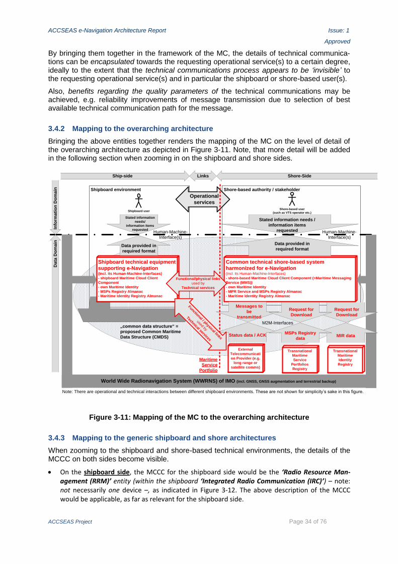
ACCSEAS e-Navigation Architecture Report Issue: 1
Approved
ACCSEAS Project Page 34 of 76
By bringing them together in the framework of the MC, the details of technical communica-tions can be encapsulated towards the requesting operational service(s) to a certain degree, ideally to the extent that the technical communications process appears to be ‘invisible’ to the requesting operational service(s) and in particular the shipboard or shore-based user(s).
Also, benefits regarding the quality parameters of the technical communications may be achieved, e.g. reliability improvements of message transmission due to selection of best available technical communication path for the message.
3.4.2 Mapping to the overarching architecture
Bringing the above entities together renders the mapping of the MC on the level of detail of the overarching architecture as depicted in Figure 3-11. Note, that more detail will be added in the following section when zooming in on the shipboard and shore sides.
Shipboard environment Shore-based authority / stakeholder
Shipboard userShore-based user
(such as VTS operator etc.)
Ship-side Links Shore-Side
Info
rma
tio
n D
om
ain
Da
ta D
om
ain
Common technical shore-based system
harmonized for e-Navigation(incl. its Human-Machine-Interfaces)
- shore-based Maritime Cloud Client Component (=Maritime Messaging
Service (MMS))
- own Maritime Identity
- MPR Service and MSPs Registry Almanac
- Maritime Identity Registry Almanac
Shipboard technical equipment
supporting e-Navigation(incl. its Human-Machine-Interfaces)
- shipboard Maritime Cloud Client
Component
- own Maritime Identity
- MSPs Registry Almanac
- Maritime Identity Registry Almanac
Data provided in
required format
Stated information
needs/
information items
requested
Data provided in
required format
Stated information needs /
information items
requested
Operational
services
Messages to
be
transmitted
Status data / ACK
M2M-Interfaces
Human-Machine-
Interface(s)
Human-Machine-
Interface(s)
World Wide Radionavigation System (WWRNS) of IMO (incl. GNSS, GNSS augmentation and terrestrial backup)
„common data structure“ =
proposed Common Maritime
Data Structure (CMDS)
Maritime
Service
Portfolio
Note: There are operational and technical interactions between different shipboard environments. These are not shown for simplicity’s sake in this figure.
External
Telecommunicati
on Provider (e.g.
long range or
satellite comms)
Functional / physical links
used by
Technical services
Functional/physical links
used by
Technical services
Request for
Download
MIR data
Transnational
Maritime
Identity
Registry
Request for
Download
MSPs Registry
data
Transnational
Maritime
Service
Portfolios
Registry
Figure 3-11: Mapping of the MC to the overarching architecture
3.4.3 Mapping to the generic shipboard and shore architectures
When zooming to the shipboard and shore-based technical environments, the details of the MCCC on both sides become visible.
On the shipboard side, the MCCC for the shipboard side would be the ‘Radio Resource Man-agement (RRM)’ entity (within the shipboard ‘Integrated Radio Communication (IRC)’) – note: not necessarily one device –, as indicated in Figure 3-12. The above description of the MCCC would be applicable, as far as relevant for the shipboard side.

ACCSEAS e-Navigation Architecture Report Issue: 1
Approved
ACCSEAS Project Page 35 of 76
While the terminal equipment of the various telecommunications technologies employed would reside on the Sensor/Source Layer using CMDS, the RRM, the shipboard MSPs Registry Almanac and the shipboard MIR Almanac would reside on the Data Processing Layer (Figure 3-12).
Certainly, there would be a need for the shipboard user to configure the MCCC according to needs and to receive appropriate status information on a HMI. This would reside on the Opera-tional Layer, incl. provision of HMIs expanding the existing functionality block Status and Data Display as indicated in Figure 3-12.
Shipboard copies of MSPs Registry, i.e. the MSPs Registry Almanac, and Maritime Identity Registry, i.e. Maritime Identity Registry Almanac.
MSPs, …)
User configuration of communications means + status display
MaritimeIdentity RegistryAlmanac
Shipboard „Maritime Cloud client component“
Shipboard elecommunications terminal equipment for various physical link technologies
Figure 3-12: Mapping of the MC to the generic shipboard architecture
Implementing the shipboard side of the MC concept by an existing IMO instrument, as amended: At present there is no international description for the shipboard entity RRM in the spirit of the MC. There is however an existing IMO Resolution A.811(19) entitled ‘Performance Standards for a shipborne Integrated Radiocommunication System (IRCS) when Used in the GMDSS’ (IMO 1995). In that document an IRCS is defined as ‘a system in which individual radio-communication equipment and installations are used as sensors, i.e. without the need for their own control units, providing outputs to and accepting inputs from the operator’s position, called workstations’ (IMO 1995, Annex, para 1.1). This is exactly the scope of the dotted line in Figure 3-12; hence the name of that bundle of entities as ‘Integrated Radio Communication’ in Figure 3-12.
The present IMO Resolution A.811(19) is confined to the scope of GMDSS. As introduced in the ‘B&P Report,’ the GMDSS will be modernized and e-Navigation principles will likely also apply to
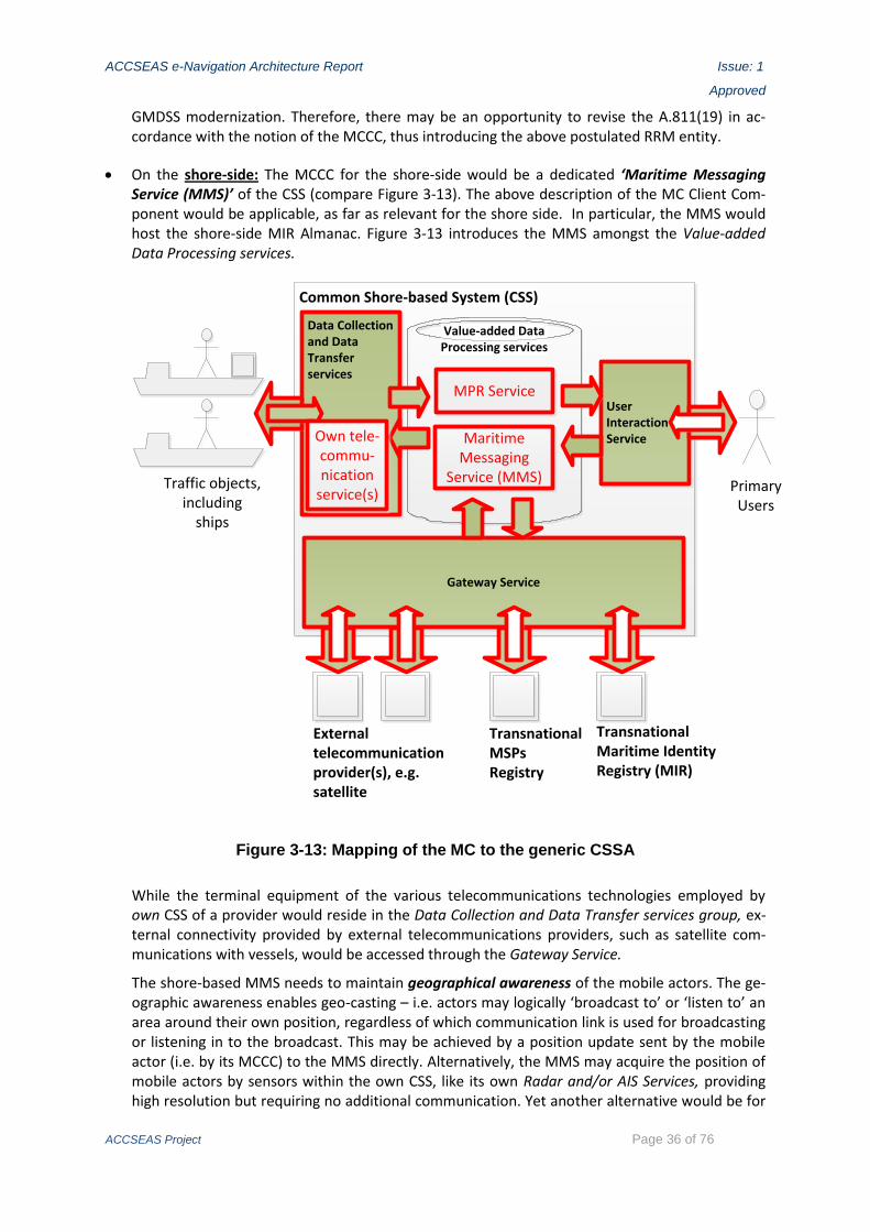
ACCSEAS e-Navigation Architecture Report Issue: 1
Approved
ACCSEAS Project Page 36 of 76
GMDSS modernization. Therefore, there may be an opportunity to revise the A.811(19) in ac-cordance with the notion of the MCCC, thus introducing the above postulated RRM entity.
On the shore-side: The MCCC for the shore-side would be a dedicated ‘Maritime Messaging Service (MMS)’ of the CSS (compare Figure 3-13). The above description of the MC Client Com-ponent would be applicable, as far as relevant for the shore side. In particular, the MMS would host the shore-side MIR Almanac. Figure 3-13 introduces the MMS amongst the Value-added Data Processing services.
Common Shore-based System (CSS)
Value-added Data Processing services
PrimaryUsers
Traffic objects,including
ships
Data Collection and Data Transfer services
UserInteraction Service
Gateway Service
MPR Service
Maritime Messaging
Service (MMS)
Transnational MSPs Registry
Transnational Maritime Identity Registry (MIR)
External telecommunicationprovider(s), e.g. satellite
Own tele-commu-nication
service(s)
Figure 3-13: Mapping of the MC to the generic CSSA
While the terminal equipment of the various telecommunications technologies employed by own CSS of a provider would reside in the Data Collection and Data Transfer services group, ex-ternal connectivity provided by external telecommunications providers, such as satellite com-munications with vessels, would be accessed through the Gateway Service.
The shore-based MMS needs to maintain geographical awareness of the mobile actors. The ge-ographic awareness enables geo-casting – i.e. actors may logically ‘broadcast to’ or ‘listen to’ an area around their own position, regardless of which communication link is used for broadcasting or listening in to the broadcast. This may be achieved by a position update sent by the mobile actor (i.e. by its MCCC) to the MMS directly. Alternatively, the MMS may acquire the position of mobile actors by sensors within the own CSS, like its own Radar and/or AIS Services, providing high resolution but requiring no additional communication. Yet another alternative would be for

ACCSEAS e-Navigation Architecture Report Issue: 1
Approved
ACCSEAS Project Page 37 of 76
the MMS to connect via the Gateway Service to a long range telecommunication service provid-er, such as a satellite based telecommunication service.
Certainly, there would be a need for the shore-based user to configure the MCCC according to needs and to receive appropriate status information on a HMI. This would reside in the User In-teraction Service.
For a description of the MSPs part of the mapping of the MC compare description at candidate solution ‘MSPs’ above. For simplicity’s sake the MPR Service’s connectivity is shown only simpli-fied. For a full description refer to candidate solution ‘MSPs’ above.
3.4.4 The functionality of ‘Application Interfaces (API)’ of MC Client Components
When interfacing a MCCC to other entities of own system (either shipboard or shore-based), it would need to have an ‘Application Interface (API).’ The API of any MCCC will provide services for
security through online use of the MIR or offline use provided by their copy of the MIR, i.e. their MIR Almanacs;
service discovery through online use of the MSPs Registry or offline use provided by their MSPs Registry Almanacs;
provision of dynamic functionality to another participant of the MC, e.g. sending relevant data;
communication through generic communication primitives seamlessly roamed to appropriate available communication systems based on a user defined rule base.
Considering the differences of the shipboard and the shore-side, the architectural shapes of the MC Client Components for the shipboard and the shore-side will be different while the functionalities or services their APIs deliver to the requesting entity will be similar.
Note, that the above ‘services’ of the API have been called ‘Basic Services’ (of a shore-based service) in the context of the CSSA to avoid confusion with the notion of services with-in the MSPs.

ACCSEAS e-Navigation Architecture Report Issue: 1
Approved
ACCSEAS Project Page 38 of 76
3.5 Mapping of the ‘Innovative Architecture for Ship Positioning’
Two candidate solutions contribute to the same goal, namely to develop an innovative archi-tecture for ship positioning, thus creating synergy to the benefit of the users. Those two can-didates are:
the Multi Source Positioning Service (MSPS) and
the R-Mode at existing shore-based MF DGNSS and AIS Services.
It is possible to map those two candidate solutions into one joint architectural mapping.
3.5.1 Joint mapping to the overarching architecture
The Global Navigation Satellite Systems (GNSS) recognized within the IMO defined World Wide Radionavigation System (WWRNS) are the major source of, in particular, positioning data for the shipboard side as well as, in particular, timing data for the shore-side. This is indicated by the all-embracing ‘bracket’ of the WWRNS in Figure 3-14 (highlighted).
As explained in the ‘B&P Report,’ the GNSS exhibit some specific vulnerabilities regarding their availability and reliability as required for safety critical applications. This prompted the development and implementation of the above two candidate solutions both of which are indicated in Figure 3-14 concurrently and thus show their seamless mutual support.
Shipboard environment Shore-based authority / stakeholder
Shipboard userShore-based user
(such as VTS operator etc.)
Shore-based
system
of different
stakeholder
Shore-based
system
of different
stakeholder
Ship-side Links Shore-Side
Info
rma
tio
n D
om
ain
Da
ta D
om
ain
Common technical
shore-based system
harmonized for e-Navigation(incl. its Human-Machine-Interfaces)
Shipboard technical
equipment supporting
e-Navigation(incl. its Human-Machine-Interfaces)
Data provided in
required format
Stated information
needs/
information items
requested
Data provided in
required format
Stated information needs /
information items
requested
Operational
services
Stated data
request
Data provided in
required format
Data provided
in required
format
Stated data
request
Machine-to-Machine-
Interfaces
Human-Machine-
Interface(s)
Human-Machine-
Interface(s)
World Wide Radionavigation System (WWRNS) of IMO (incl. GNSS, GNSS augmentation and terrestrial backup)
„common data structure“ =
proposed Common Maritime
Data Structure (CMDS)
Resilient PNT Shore Provision = Resilient PNT part of (NSR-) Maritime Service
Portfolios (MSPs)
Note: There are operational and technical interactions between different shipboard environments. These are not shown for simplicity’s sake in this figure.
Appropirate display of
Resilient PNT data, Resilient
PNT quality parameters;
Resilient PNT alerts
Multi Source Positioning
Service (MSPS)
(provided to the mariner via HMI)
e.g. D-Modes of MF DGNSS
System and AIS Service
e.g. R-Modes of MF DGNSS
System and AIS Service;
eLoranTechnical Radio Navigation
Backup services
Technical Radio Navigation
Augmentation services
Multi Source Positioning
Service (MSPS) (provided to shipboard equipment by
M2M interfaces)
Figure 3-14: Mapping of the ‘Innovative Architecture for Ship Positioning’ to the over-arching architecture
The MSPS resides on the shipboard side, taking in data acquired and stored in the ‘ship-board technical equipment supporting e-Navigation’ itself, data received from the GNSSs

ACCSEAS e-Navigation Architecture Report Issue: 1
Approved
ACCSEAS Project Page 39 of 76
within the WWRNS as well as data received from terrestrial augmentation (such as DGNSS) and/or backup systems (such as R-Mode and eLoran).
The MSPS evaluates all available data to calculate the resilient PNT data parameters intro-duced in the ‘B&P Report’ at both
an API, i.e. an M2M allowing the use of the MSPS’ calculation for the vessel’s ‘shipboard tech-nical equipment supporting e-Navigation’ itself (indicated in Figure 3-14 by a dotted bold line on the shipboard side) as well as
an HMI which presents the data as information to the mariner in the portrayal modes required (indicated in Figure 3-14 by a solid bold line on the shipboard side).
The R-Mode is a method to provide a terrestrial backup system using the existing shore-based MF DGNSS and AIS Services’ signals by adding timing data to them without affecting their primary applications.
Hence, the R-Mode contributes to backup services of the ‘Resilient PNT Shore Provision’ part of the MSPs (indicated in Figure 3-14 by highlighting of the dotted vertical line of the MSPs, the CSS as well as the two arrows indicating the ‘Technical Radio Navigation Aug-mentation services’ and the ‘Technical Radio Navigation services’).
Notes:
The term ‘service’ is used here with two different meanings: In the case of the MSPS the term ‘service’ is used in the context of an API or HMI, while ‘service’ in the case of the ‘R-Mode’ is used in the context of the MSPs thus designating shore-provision to shipping at large.
The Resilient PNT Shore Provision is a Maritime Service Portfolio (MSP) of technical services, i.e. a ‘purposeful bundle’ in the technical domain, and comprises the Technical Radio Navigation Augmentation services and the Technical Radio Navigation services. Both are again ‘purposeful bundles’ of technical services and hence technical MSPs because there are several shore-based technical services in each of those MSPs. For details compare the mapping to the CSS below.
The one-directional arrows for both the Technical Radio Navigation Augmentation services as well as for the Technical Radio Navigation services indicate that they are open broadcast services not requiring a feedback channel from the shipboard electronic equipment. (It should be noted that the AIS reports of vessels already at present provide a feedback channel on the PNT data quality available at the vessel, although with limited content.)
eLoran, from an ontological point of view, may also be construed as an ‘R-Mode’ on the carrier of a shore-transmitted Loran-C-signal. During ACCSEAS the term ‘R-Mode’ was confined to the addition of timing data to the signals from MF DGNSS and AIS Services, though.
3.5.2 Mapping to the generic shipboard and shore architectures
When zooming to the shipboard and shore-based technical environments, the details of the Innovative Architecture for Ship Positioning on both sides become visible.
On the shipboard side, this innovative architecture affects all layers of the generic shipboard architecture (Figure 3-15) as follows:

ACCSEAS e-Navigation Architecture Report Issue: 1
Approved
ACCSEAS Project Page 40 of 76
PNT
Sensors
Depth
sensor
Radar
Sensor(s)
Sensor/
Sourc
e L
ayer
usin
g C
MD
S
Consistent Common Reference System
PNT
evaluation
System
Data
selectionIntegrated Radio
Communication
VHF
Radio Resource
Management(selection, filtering, routing,
signaling and alerting)
Collision
avoidance
Route
monitoring
Nav.
Control
Data
Alert
manag.
Other bridge
systemsIntegrated Navigation System (INS)
Data
Pro
cessin
g L
ayer
Opera
tional Layer,
incl.
pro
vis
ion o
f H
MIs
Status
and Data
Display
Active INS Data base
(Route information,
SENC, Hydrographical,
Weather,…)
BAM
INS Communication
Safety …
Inte
rfa
ce
to
e
xte
rna
l
syste
ms
SAT
Vessel
parametersStatic data, pre-packed
(e.g. ENC data)
Dynamic /
real-time data
AIS …
…
HF
MF
LF
…
Portrayal of Resilient PNT quality parameters
Final resilient PNT solution and Resilient PNT quality parameters, such as the Horizontal Protection Level (HPL), calculated here using input from various available sources
Including GNSS receivers and receivers for terrestrial radio navigation
augmentation (D-Mode) and/or backup systems (e.g. R-Mode, eLoran), as
well as multi-source radio navigation receiver(s)
Status of Resilient PNT entities
(components, functionalities)
Resilient PNT alert(s) based e.g. on
the Horizontal Alert Limit (HAL)
Usage of Resilient PNT
solutions
Figure 3-15: Mapping of the Innovative Architecture for Ship Positioning / Multi-Source Position Service (MSPS) to the generic shipboard architecture
The ‘Operational Layer, incl. provision for HMI’s’ would contain all functionality to present the MSPS’ Resilient PNT solutions to the mariner in the required display mode(s). Due to the funda-mental importance of positioning data for any vessel’s operation, basically all modules of the INS would host some part of the whole presentation functionality for the MSPS’ Resilient PNT solu-tions:
- The INS modules ‘Collision avoidance’ and ‘Route Monitoring’ would use the MSPS’ Resilient PNT solutions to show own vessel’s position in relation to the other vessels around.
- The INS module ‘Navigation Control Data’ would provide an opportunity to appropriately display the Resilient PNT solutions’ quality parameters to the mariner.
- The INS module ‘Alert Management’ would provide the opportunity to program Resilient PNT alert thresholds, e.g. the Horizontal Alert Limit (HAL), and to integrate this alert into the alert hierarchy of the INS at large. Both would require appropriate display of the set-up op-portunities for the mariner as well as of the specific Resilient PNT alert indications them-selves: I.e. how would (a) postulated ‘Resilient PNT alert(s)’ make itself/themselves visible and/or audible in this INS module as well as in other INS modules affected.
- The INS module ‘Status and Data Display’ would provide the opportunity to display to the mariner the status of the Resilient PNT entities themselves, i.e. the status of Resilient PNT components and functionalities within the vessel’s own shipboard equipment as well as the status of the WWRNS and/or Resilient PNT Shore Provision.
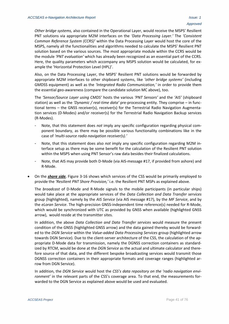
ACCSEAS e-Navigation Architecture Report Issue: 1
Approved
ACCSEAS Project Page 41 of 76
Other bridge systems, also contained in the Operational Layer, would receive the MSPS’ Resilient PNT solutions via appropriate M2M interfaces on the ‘Data Processing Layer.’ The ‘Consistent Common Reference System (CCRS)’ within the Data Processing Layer would host the core of the MSPS, namely all the functionalities and algorithms needed to calculate the MSPS’ Resilient PNT solution based on the various sources. The most appropriate module within the CCRS would be the module ‘PNT evaluation’ which has already been recognized as an essential part of the CCRS. Here, the quality parameters which accompany any MSPS solution would be calculated, for ex-ample the ‘Horizontal Protection Level (HPL)’.
Also, on the Data Processing Layer, the MSPS’ Resilient PNT solutions would be forwarded by appropriate M2M interfaces to other shipboard systems, like ‘other bridge systems’ (including GMDSS equipment) as well as the ‘Integrated Radio Communication,’ in order to provide them the essential geo-awareness (compare the candidate solution MC above), too.
The ‘Sensor/Source Layer using CMDS’ hosts the various ‘PNT Sensors’ and the ‘AIS’ (shipboard station) as well as the ‘Dynamic / real-time data’ pre-processing entity. They comprise – in func-tional terms – the GNSS receiver(s), receiver(s) for the Terrestrial Radio Navigation Augmenta-tion services (D-Modes) and/or receiver(s) for the Terrestrial Radio Navigation Backup services (R-Modes).
- Note, that this statement does not imply any specific configuration regarding physical com-ponent boundary, as there may be possible various functionality combinations like in the case of ‘multi-source radio navigation receiver(s).’
- Note, that this statement does also not imply any specific configuration regarding M2M in-terface setup as there may be some benefit for the calculation of the Resilient PNT solution within the MSPS when using PNT Sensor’s raw data besides their finalized calculations.
- Note, that AIS may provide both D-Mode (via AIS-message #17, if provided from ashore) and R-Mode.
On the shore side, Figure 3-16 shows which services of the CSS would be primarily employed to provide the ‘Resilient PNT Shore Provision,’ i.e. the Resilient PNT MSPs as explained above.
The broadcast of D-Mode and R-Mode signals to the mobile participants (in particular ships) would take place at the appropriate services of the Data Collection and Data Transfer services group (highlighted), namely by the AIS Service (via AIS message #17), by the MF Service, and by the eLoran Service. The high-precision GNSS-independent time reference(s) needed for R-Mode, which would be synchronized with UTC as provided by GNSS when available (highlighted GNSS arrow), would reside at the transmitter sites.
In addition, the above Data Collection and Data Transfer services would measure the present condition of the GNSS (highlighted GNSS arrow) and the data gained thereby would be forward-ed to the DGN Service within the Value-added Data Processing Services group (highlighted arrow towards DGN Service). Due to the client-server architecture of the CSS, the calculation of the ap-propriate D-Mode data for transmission, namely the DGNSS correction containers as standard-ized by RTCM, would be done at the DGN Service as the actual and ultimate calculator and there-fore source of that data, and the different bespoke broadcasting services would transmit those DGNSS correction containers in their appropriate formats and coverage ranges (highlighted ar-row from DGN Service).
In addition, the DGN Service would host the CSS’s data repository on the ‘radio navigation envi-ronment’ in the relevant parts of the CSS’s coverage area. To that end, the measurements for-warded to the DGN Service as explained above would be used and evaluated.

ACCSEAS e-Navigation Architecture Report Issue: 1
Approved
ACCSEAS Project Page 42 of 76
Common Shore-based System (CSS)
Value-added Data Processing Services
Data Collection and Data Transfer services
DGN Service
AIS Service
MF Service
eLORAN
Traffic objects,including
ships
Shore based„third party“ users
Gateway Service
PrimaryUsers
UserInteraction
Service
Resilient PNT Shore Provision= Resilient PNT part of the (NSR-)MSPs
D-Modes and R-Modes of MF DGNSS System and AIS Service
GNSS
Figure 3-16: Mapping of the Innovative Architecture for Ship Positioning / R-Modes at MF DGNSS and AIS Services, together with eLoran, to the generic CSSA
If requested by shore-based users, this radio navigation environment status data would be for-warded from the DGN Service to the User Interaction Service (not highlighted) for appropriate presentation by a HMI at the CSS primary users’ workplaces, like in VTS centres, or to other shore-based systems via the Gateway Service (not highlighted) using an appropriate M2M inter-face standard.
Note: While the shore-side does not need a MSPS as such, the functionalities and algorithms similar to those of the MSPS can be used within the DGN Service to determine and evaluate the radio navigation environment in the CSS’s coverage area, as applicable. This may assist in creat-ing awareness for the present state of the surrounding radio navigation environment, similar to the already presently required awareness for the physical environment of the waterway itself. This in turn may have a direct benefit to shore-based users, e.g. at VTS Centers, when evaluating position reports received from vessels (both manually and automatically) and an indirect benefit to shipboard users because shore-based users may provide navigation related information which fits better to the vessel’s situation because the radio navigation environment is taken into ac-count.
For further detail compare the corresponding descriptions of the MSPS and the R-Mode as published in separate description documents and in particular in the R-Mode Feasibility Study (several parts).

ACCSEAS e-Navigation Architecture Report Issue: 1
Approved
ACCSEAS Project Page 43 of 76
3.6 Mapping of the candidate solution ‘Maritime Safety Information/Notices to Mariners (MSI/NM) Service’
3.6.1 Mapping to the overarching architecture
The Maritime Safety Information/Notices to Mariners (MSI/MN) Service is an operational service provided from ashore to shipping at large, i.e. as broadcast. Hence, it would be part of any MSPs, where provided. The main point in operational terms of this service is
to seamlessly integrate the abstract information entities ‘Maritime Safety Information (MSI)’ and ‘Notices to Mariners (NM)’ and possibly even chart corrections into one new consistent abstract information entity called ‘Maritime Information Message (MIM),’ and
to broadcast those MIMs generated by the appropriate body on the shore-side, namely the ‘Na-tional Coordinator,’ by means of a seamless technical carrier environment to the shipping at large, such as the MC, instead of the several technological frameworks used presently (which will be reduced in importance over time and eventually be replaced after a migration period).
Note: There may be additional useful functionalities introduced in the process, namely e.g. the means to query shore-based MIM database(s) for historical MIMs. But this does not affect the above main point of this candidate solution and is therefore not highlighted in the following.
Therefore, the candidate solution on the operational service might as well have been called Maritime Information Message Service or MIM Service for short.
While the task at hand appears to be easy to accomplish, this is not the case considering the intricacies incurred on the technical level. This is immediately obvious by the mapping to the overarching architecture (compare Figure 3-17).

ACCSEAS e-Navigation Architecture Report Issue: 1
Approved
ACCSEAS Project Page 44 of 76
Shipboard environment Shore-based authority / stakeholder
Shipboard userShore-based user
(such as „National Coordinator“)
Shore-based
system
of different
stakeholder
Shore-based
system
of different
stakeholder
Ship-side Links Shore-SideIn
form
ati
on
Do
ma
inD
ata
Do
ma
in
Common technical
shore-based system
harmonized for e-Navigation(incl. its Human-Machine-Interfaces)
Shipboard technical equipment
supporting e-Navigation (incl. its
Human-Machine-Interfaces)
Request for Maritime
Information Messages
(current, historical)
MIMs presented
Request for
external data
needed for MIM
composition
Prompts for MIM
composition +
Data provided for MIM
composition
(Historical)
MIM delivered
Request for
(historical) MIM
Machine-to-Machine-
Interfaces
Human-Machine-
Interface(s)
Human-Machine-
Interface(s)
World Wide Radionavigation System (WWRNS) of IMO (incl. GNSS, GNSS augmentation and terrestrial backup)
„common data structure“ =
proposed Common Maritime
Data Structure (CMDS)
Maritime
Service
Portfolio
Note: There are operational and technical interactions between different shipboard environments. These are not shown for simplicity’s sake in this figure.
MIM broadcast dissemination
by „Maritime Cloud“
Various appropriate
telecommunications services
(Historical)
Maritime Information
Messages (MIM)
Database
(Historical)
Maritime Information
Messages (MIM)
Almanac
Data for new MIM
composition + historical
MIM provided
Request for data needed to
compose Maritime Information
Messages (MIM)
Broadcast of MSI/NM by traditional
technical service(s)
such as NAVTEX
Maritime Information Message Service (MIM Service)
aka MSI/NM Service (= Operational service)
Figure 3-17: Mapping of the ‘MSI/NM Service’ or ‘MIM Service’ to the overarching ar-chitecture
For Figure 3-17 the following should be considered:
The operational service is highlighted, as are the operational stakeholders involved (in dark red). Due to the nature of the operational service, the information flow is mainly one-directional from ashore to the mariners.
Even on an upper technical functionality level, the mapping shows that basically all technical shipboard, shore-based, and link components of the overarching architecture are involved in a primary way when supporting the operational service (highlighted in light red). This illustrates at first sight the above statement, that the technical implementation for such an integrated opera-tional serviced results in certain technical intricacies.
Different stages of operational and technical data processing are blended together in Figure 3-17 for reasons of clarity, i.e. the operational work flow stages are not graphically differentiated and are thus only alluded to by textual statements:
- A prompt for any MIM (broadcast) activity would generally originate from an external shore-based system, because – as the name ‘National Coordinator’ implies –, the shore-based technical system of the ‘National Coordinator’ is most likely the ultimate source of the operation information and of the operational conditions to be transmitted or conveyed to shipping by MIM. This is indicated by ‘prompts for MIM composition’ sent to own system via M2M from a ‘Shore-based system of different stakeholder’ (right lower corner Figure 3-17).
- MIM Composition phase: Before any MIM would be broadcasted, there would be a need for the ‘National Coordinator’ to acquire all relevant operational information which would be provided to him by the shore-based technical system upon data query or as it is received (compare ‘data for new MIM composition’ at HMI to ‘National Coordinator’). This required

ACCSEAS e-Navigation Architecture Report Issue: 1
Approved
ACCSEAS Project Page 45 of 76
data may have been stored in the own shore-based technical system already by processes not relevant here, or it may be retrieved from external systems by request/delivery interac-tion of own shore-based system with another or even several other shore-based systems via M2Ms (compare ‘request for external data needed for MIM composition’ / ‘data provided for MIM composition’).
- MIM Transmission phase: When a MIM would have been compiled, the ‘National Coordina-tor’ would release it to own shore-based technical system to be transmitted via appropriate means, namely via the MC and – at least for a migration period – via traditional technical services, such as NAVTEX. The MIM would be received by vessels’ shipboard technical equipment and would be stored in shipboard technical equipment for future reference and also be presented to the mariners in an appropriate display format, immediately and/or up-on query at a later time. Compare involvement of technical services shore-to-ship and of shipboard technical equipment in Figure 3-17.
- Query for historical MMI stage: The stored historical MMI may be retrieved by query from own system – in the case of the shipboard electronic equipment: from the MIM Almanac – or from the National Coordinator’s shore-based MIM Database – in the case of the vessel by remote query by appropriate technical means (e.g. via the MC; not shown in Figure 3-17).
- Note: While not done so in Figure 3-17, it is possible and a straight forward task to show the above different operational work flow stages in several individual figures like Figure 3-17, each of which would only highlight one stage at a time. This might be a worthwhile exercise for a high level application analysis in the future.
The candidate solution uses the MC as a technical service framework for the technical communi-cation of MIM as introduced above in the section on the MC. This part of the technical service framework is therefore not be shown in detail for reasons of clarity, although this is operative to support ‘in the background.’ Rather, those entities will be represented in the mapping to the overarching architecture only in iconic or symbolic way (compare dotted-line box at place of technical services at ‘Links’ part of Figure 3-17). This means that the benefit stemming from en-capsulation of the MC can now be reaped.
Finally, it should be noted, that in a secondary way, also the entities not highlighted in Figure 3-17 for reasons of clarity are involved:
- The MMI would certainly have a data modelling representation in the CMDS.
- The MSPs would include the MIM Service or the MSI/NM Service as well as all technical ser-vices employed for the dissemination of the MIM.
- The WWRNS’ contribution would be required for the geo-awareness which is highly relevant for MIM (or MSI/NM).
For further detail compare the corresponding ACCSEAS MSI/NM Service Description.
ACCSEAS e-Navigation Architecture Report Issue: 1
Approved
ACCSEAS Project Page 46 of 76
3.7 Mapping of the candidate solution ‘Augmented Reality / Head-Up-Displays (HUDs)’
3.7.1 Mapping to the overarching architecture
The ‘B&P Report’ introduced the candidate solution ‘Augmented Reality (AR) / Head-Up-Displays (HUDs)’ as a shipboard application for the main purpose of collision avoidance. Its fundamental idea is to project graphical features into the visual field of the mariner when ‘looking out of the window’ – hence Head-Up-Display – which highlight certain features of the reality surrounding own vessel – hence Augmented Reality (AR) – and thereby draw the specific attention of the mariner to those features of the surrounding reality. Relevant fea-tures would be those which are of prime relevance for the mariner’s tasks of collision avoid-ance and route monitoring. Considering the vessel’s voyage direction, the most relevant fea-tures would lie ahead of the vessel.
The technical means to project those AR features into the visual field of the mariner could be an appropriate projection on the front screen of the bridge as well as a pair of electronic goggle worn by the mariner. Those technical components would be part of the HMI of the ‘shipboard technical equipment supporting e-Navigation.’ Although this idea may sound sim-ple, there are certain challenges involved for the engineering of a useful implementation of such an HMI. For the architectural mapping at hand suffice it to say that such HMIs are technically feasible and this is assumed henceforth.
The above introduction rendered the place of candidate solution the shipboard side, only, as highlighted in Figure 3-18.
Shipboard environment Shore-based authority / stakeholder
Shipboard userShore-based user
(such as VTS operator etc.)
Shore-based
system
of different
stakeholder
Shore-based
system
of different
stakeholder
Ship-side Links Shore-Side
Info
rma
tio
n D
om
ain
Da
ta D
om
ain
Common technical
shore-based system
harmonized for e-Navigation(incl. its Human-Machine-Interfaces)
Shipboard technical
equipment supporting
e-Navigation(incl. its Human-Machine-Interfaces)
Data provided in
required format
Stated information needs/
information items requested
Data provided as
Augmented Reality overlay /
Head-up display
Stated information needs /
information items
requested
Operational
services
Stated data
request
Data provided in
required format
Data provided
in required
format
Stated data
request
Machine-to-Machine-
Interfaces
Human-Machine-
Interface(s)
Human-Machine-
Interface(s)
World Wide Radionavigation System (WWRNS) of IMO (incl. GNSS, GNSS augmentation and terrestrial backup)
„common data structure“ =
proposed Common Maritime
Data Structure (CMDS)
Functional links
used by
Technical services
Physical links
used by
Technical services
(NSR-)Maritime Service
Portfolios (MSPs)
Note: There are operational and technical interactions between different shipboard environments. These are not shown for simplicity’s sake in this figure.
Figure 3-18: Mapping of the AR/HUDs to the overarching architecture
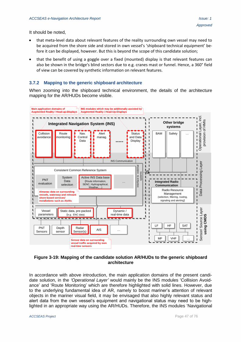
ACCSEAS e-Navigation Architecture Report Issue: 1
Approved
ACCSEAS Project Page 47 of 76
It should be noted,
that meta-level data about relevant features of the reality surrounding own vessel may need to be acquired from the shore side and stored in own vessel’s ‘shipboard technical equipment’ be-fore it can be displayed, however. But this is beyond the scope of this candidate solution;
that the benefit of using a goggle over a fixed (mounted) display is that relevant features can also be shown in the bridge's blind sectors due to e.g. cranes mast or funnel. Hence, a 360° field of view can be covered by synthetic information on relevant features.
3.7.2 Mapping to the generic shipboard architecture
When zooming into the shipboard technical environment, the details of the architecture mapping for the AR/HUDs become visible.
PNT
Sensors
Depth
sensor
Radar
Sensor(s)
Sensor/
Sourc
e L
ayer
usin
g C
MD
S
Consistent Common Reference System
PNT
evaluation
System
Data
selectionIntegrated Radio
Communication
VHF
Radio Resource
Management(selection, filtering, routing,
signaling and alerting)
Collision
avoidance
Route
monitoring
Nav.
Control
Data
Alert
manag.
Other bridge
systemsIntegrated Navigation System (INS)
Data
Pro
cessin
g L
ayer
Opera
tional Layer,
incl.
pro
vis
ion o
f H
MIs
Status
and Data
Display
Active INS Data base
(Route information,
SENC, Hydrographical,
Weather,…)
BAM
INS Communication
Safety …
Inte
rface to exte
rnal
syste
ms
SAT
Vessel
parametersStatic data, pre-packed
(e.g. ENC data)
Dynamic /
real-time data
AIS …
…
HF
MF
LF
…Sensor data on surrounding
vessel traffic acquired by own
real-time sensors
INS modules which may be additionally assisted by
Augmented Reality / Head-Up-Displays
Main application domains of
Augmented Reality / Head-up-Displays
Almanac data on surrounding
vessels, waterway and relevant
shore-based services/
installations such as AtoNs
Figure 3-19: Mapping of the candidate solution AR/HUDs to the generic shipboard architecture
In accordance with above introduction, the main application domains of the present candi-date solution, in the ‘Operational Layer’ would mainly be the INS modules ‘Collision Avoid-ance’ and ‘Route Monitoring’ which are therefore highlighted with solid lines. However, due to the underlying fundamental idea of AR, namely to boost mariner’s attention of relevant objects in the mariner visual field, it may be envisaged that also highly relevant status and alert data from the own vessel’s equipment and navigational status may need to be high-lighted in an appropriate way using the AR/HUDs. Therefore, the INS modules ‘Navigational
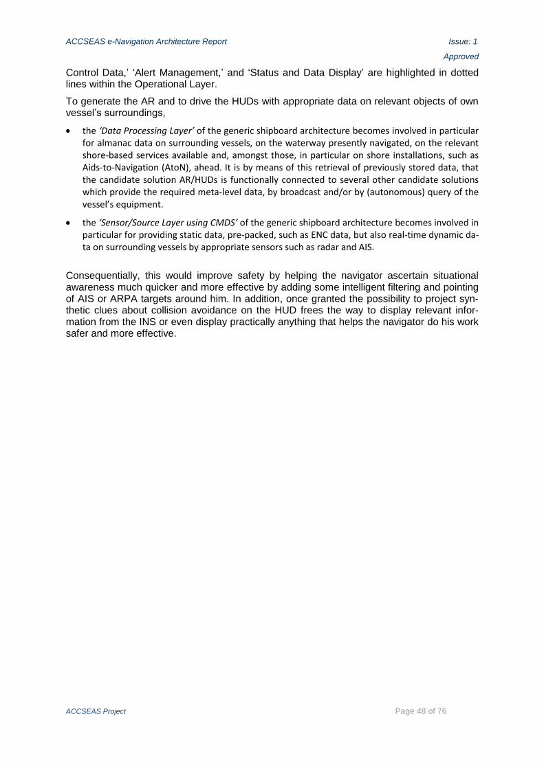
ACCSEAS e-Navigation Architecture Report Issue: 1
Approved
ACCSEAS Project Page 48 of 76
Control Data,’ ‘Alert Management,’ and ‘Status and Data Display’ are highlighted in dotted lines within the Operational Layer.
To generate the AR and to drive the HUDs with appropriate data on relevant objects of own vessel’s surroundings,
the ‘Data Processing Layer’ of the generic shipboard architecture becomes involved in particular for almanac data on surrounding vessels, on the waterway presently navigated, on the relevant shore-based services available and, amongst those, in particular on shore installations, such as Aids-to-Navigation (AtoN), ahead. It is by means of this retrieval of previously stored data, that the candidate solution AR/HUDs is functionally connected to several other candidate solutions which provide the required meta-level data, by broadcast and/or by (autonomous) query of the vessel’s equipment.
the ‘Sensor/Source Layer using CMDS’ of the generic shipboard architecture becomes involved in particular for providing static data, pre-packed, such as ENC data, but also real-time dynamic da-ta on surrounding vessels by appropriate sensors such as radar and AIS.
Consequentially, this would improve safety by helping the navigator ascertain situational awareness much quicker and more effective by adding some intelligent filtering and pointing of AIS or ARPA targets around him. In addition, once granted the possibility to project syn-thetic clues about collision avoidance on the HUD frees the way to display relevant infor-mation from the INS or even display practically anything that helps the navigator do his work safer and more effective.

ACCSEAS e-Navigation Architecture Report Issue: 1
Approved
ACCSEAS Project Page 49 of 76
3.8 Mapping of the candidate solution ‘Harmonized Data Exchange – Employ-ing the Inter-VTS Exchange Format (IVEF)’
3.8.1 General considerations regarding the challenges of harmonisation of real-time, high reliability, and high integrity vessel tracking processes for system archi-tectures
The ‘Harmonized Data Exchange – Employing the Inter-VTS Exchange Format (IVEF)’ turns towards real-time vessel track processes customary performed at VTS as well as onboard vessels, and – more specifically – how a harmonised data exchange based on IVEF may assist there – remember ‘harmonisation’ is the key word of e-Navigation.
Referring to ‘real-time’ would mean here ‘in the order of seconds or less than a second per turnaround:’ Compare for example the very short revolution time achieved by a maritime radar antenna – in the order of less than a second to a few seconds, depending on the kind of maritime radar – or the high update frequency between vessel position reports generated by AIS, which may be as frequent as less than once per 1 second, if so commanded from a competent authority ashore, but also can reach an update frequency in autonomous mode of once per 2 seconds for fast going vessels. Even for slow moving vessels the permissible upper bound of AIS position reporting frequency is once per 10 seconds (ITU 2014, A.1, 4.2.1).
In vessel tracking there are customary correlated the requirements
for high reliability of the vessel tracks and
for high integrity and/or validation of the vessel tracks derived by processing the source data streams
with the real-time requirement.
These requirements have direct implications for both the architecture and the implementa-tion of both
the vessel track data to be exchanged as such: The vessel track data stream is expected to exhib-it only little latency (real-time!), be of high reliability and/or integrity content-wise, and be po-tentially even content-validated by usage of several sources for the same vessel track;
the vessel track data stream exchange processes at M2M interfaces between technical systems: The M2M vessel track data stream exchange process should also exhibit a real-time behaviour, be of high integrity and of high reliability.
At present, there are a limited number of data encoding formats available which would be capable of encoding vessel track data for real-time purposes, but which are tailored to the specifics of their data exchange link technologies (such as the aviation-developed ‘Asterix’ standard or the binary AIS VHF data link encoding format). This renders technology-specific, less flexible and therefore ‘harmonisation unfriendly’ data encoding formats. Also, proliferat-ing these formats too far, namely even across system boundaries, as done customary today, may potentially hamper the perspective to reap the full benefits of any open system architec-ture in the future. In particular, those benefits available when applying the encapsulation principle of state-of-the-art system engineering are at risk.
Therein lie the technological and technical challenges, namely to achieve the above high quality levels with an abstract data encoding format, such as an XML derivative, which would incur all the benefits of those state-of-the-art data encoding formats, including ease of har-monisation.

ACCSEAS e-Navigation Architecture Report Issue: 1
Approved
ACCSEAS Project Page 50 of 76
3.8.2 Mapping of harmonised IVEF-based exchange of vessel track data streams between different shore-based VTS’ technical systems to the overarching ar-chitecture
The initial use case of the IVEF was and is – as implied by its very name – the harmonized exchange of vessel track data streams via M2M interfaces between shore-based technical systems dealing with tactical, i.e. real-time vessel traffic issues, thus meeting the general challenges introduced above. Such shore-based systems are regularly deployed and oper-ated by VTS, coastguard, pilot, and port authorities, as well as other allied services. The recognition of the benefits of international harmonisation has led to the initial development of the appropriate IALA Recommendation (IALA 2011.
Vessel track data in VTS essentially is real-time data. Real-time vessel track data may have been gathered from various sensors available to a shore-based system, such as radar and AIS, and these sensor data streams may potentially have been fusioned and/or validated in the process. The point of IVEF-based harmonized data exchange is thus to exchange real-time, highly integrity-assured and/or validated, highly reliable vessel track data streams, as opposed to not integrity-assured and/or un-validated data of individual sensors’ aspectives of the movements of vessels using a data exchange means with limited reliability and/or streaming capabilities.
Also, the sensor set-up of the different shore-based systems may vary from system to sys-tem, due to different requirements of different stakeholders and to different implementation approaches.
Hence, IVEF constitutes an abstract representation of vessel track data streams with above high quality levels for M2M data exchange between technical systems, using an XML deriva-tive application encoding.
This in turn would require some appropriate data modelling of the vessel track data (stream) using methods that would securely render the above high quality levels. With the advent of e-Navigation, IMO, amongst other things of architectural relevance, has stipulated that such data modelling should be done with the IHO developed S-100 standard and its philosophy ‘as a baseline’ (IMO 2014).8
Using IVEF, a harmonized real-time exchange of vessel track data with above high quality level between different, otherwise potentially completely disparate technical systems thus becomes possible, in principle. This is shown highlighted in Figure 3-20.
Note that the real-time data gathering processes via appropriate sensors and the real-time data display processes to the users’ HMI’s are not highlighted in either system to avoid clut-tering of Figure 3-20.
8 The present IALA Recommendation on IVEF was developed well ahead in time of the ad-vent of the IMO SG’s SMTS and the IMO e-Navigation SIP; hence, it is recognized that there is a need to revise the V-145, not least to the implications of the advent of SMTS and of e-Navigation, with the view to align it properly with concepts like shore-provided services in the context of MSPs, CMDS (S-100-based), MC, CSSA, harmonized shipboard architectures, etc.
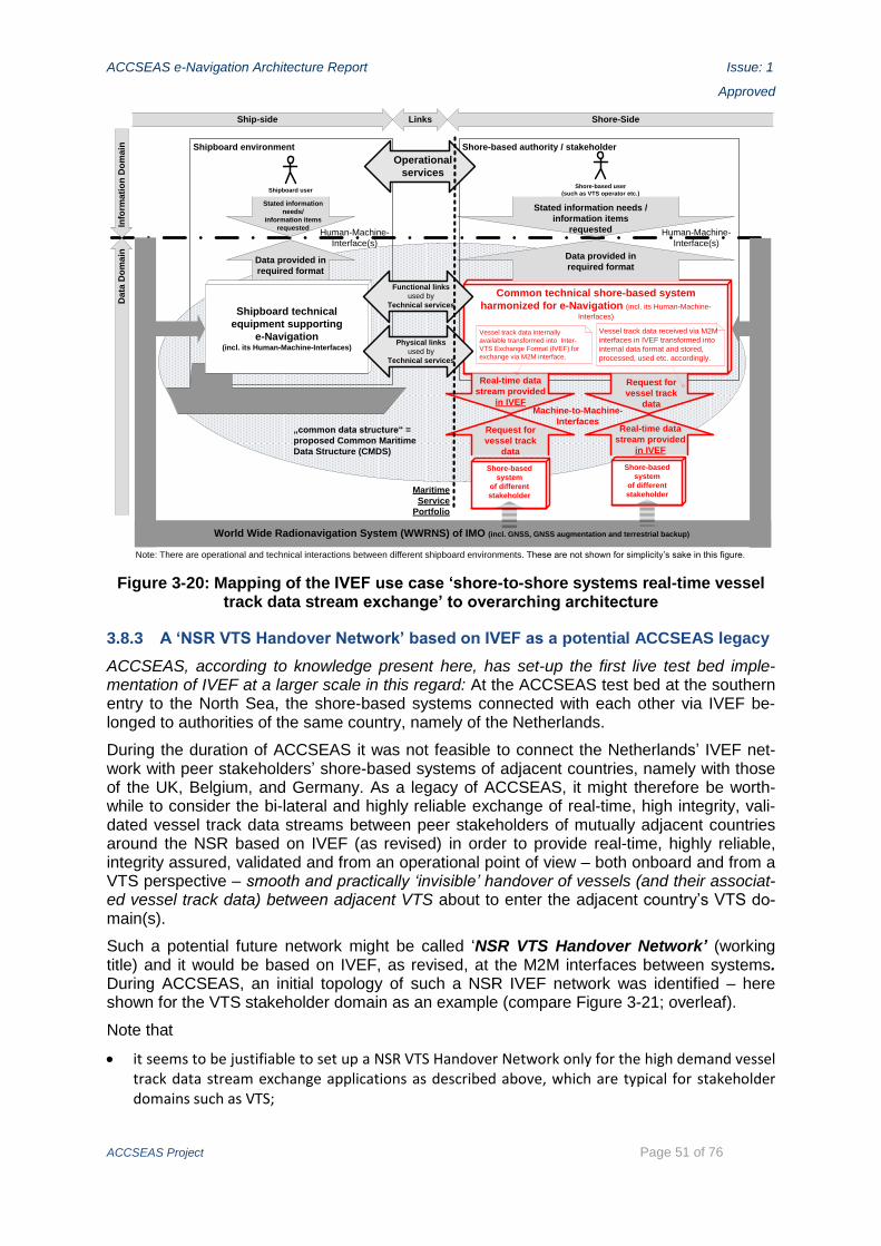
ACCSEAS e-Navigation Architecture Report Issue: 1
Approved
ACCSEAS Project Page 51 of 76
Shipboard environment Shore-based authority / stakeholder
Shipboard userShore-based user
(such as VTS operator etc.)
Shore-based
system
of different
stakeholder
Shore-based
system
of different
stakeholder
Ship-side Links Shore-SideIn
form
ati
on
Do
ma
inD
ata
Do
ma
in
Common technical shore-based system
harmonized for e-Navigation (incl. its Human-Machine-
Interfaces)Shipboard technical
equipment supporting
e-Navigation(incl. its Human-Machine-Interfaces)
Data provided in
required format
Stated information
needs/
information items
requested
Data provided in
required format
Stated information needs /
information items
requested
Operational
services
Request for
vessel track
data
Real-time data
stream provided
in IVEF
Real-time data
stream provided
in IVEF
Request for
vessel track
data
Machine-to-Machine-
Interfaces
Human-Machine-
Interface(s)
Human-Machine-
Interface(s)
World Wide Radionavigation System (WWRNS) of IMO (incl. GNSS, GNSS augmentation and terrestrial backup)
„common data structure“ =
proposed Common Maritime
Data Structure (CMDS)
Functional links
used by
Technical services
Physical links
used by
Technical services
Maritime
Service
Portfolio
Note: There are operational and technical interactions between different shipboard environments. These are not shown for simplicity’s sake in this figure.
Vessel track data internally
available transformed into Inter-
VTS Exchange Format (IVEF) for
exchange via M2M interface.
Vessel track data received via M2M
interfaces in IVEF transformed into
internal data format and stored,
processed, used etc. accordingly.
Figure 3-20: Mapping of the IVEF use case ‘shore-to-shore systems real-time vessel track data stream exchange’ to overarching architecture
3.8.3 A ‘NSR VTS Handover Network’ based on IVEF as a potential ACCSEAS legacy
ACCSEAS, according to knowledge present here, has set-up the first live test bed imple-mentation of IVEF at a larger scale in this regard: At the ACCSEAS test bed at the southern entry to the North Sea, the shore-based systems connected with each other via IVEF be-longed to authorities of the same country, namely of the Netherlands.
During the duration of ACCSEAS it was not feasible to connect the Netherlands’ IVEF net-work with peer stakeholders’ shore-based systems of adjacent countries, namely with those of the UK, Belgium, and Germany. As a legacy of ACCSEAS, it might therefore be worth-while to consider the bi-lateral and highly reliable exchange of real-time, high integrity, vali-dated vessel track data streams between peer stakeholders of mutually adjacent countries around the NSR based on IVEF (as revised) in order to provide real-time, highly reliable, integrity assured, validated and from an operational point of view – both onboard and from a VTS perspective – smooth and practically ‘invisible’ handover of vessels (and their associat-ed vessel track data) between adjacent VTS about to enter the adjacent country’s VTS do-main(s).
Such a potential future network might be called ‘NSR VTS Handover Network’ (working title) and it would be based on IVEF, as revised, at the M2M interfaces between systems. During ACCSEAS, an initial topology of such a NSR IVEF network was identified – here shown for the VTS stakeholder domain as an example (compare Figure 3-21; overleaf).
Note that
it seems to be justifiable to set up a NSR VTS Handover Network only for the high demand vessel track data stream exchange applications as described above, which are typical for stakeholder domains such as VTS;

ACCSEAS e-Navigation Architecture Report Issue: 1
Approved
ACCSEAS Project Page 52 of 76
VTS
France
VTS
UK
VTS
Belgium
VTSNetherlands
VTS
Germany
VTS
Denmark
VTS
Sweden
VTS
NorwayIVEF data exchange
IVEF
dat
a
exch
ange
IVEF
dat
a ex
chan
ge
IVEF data exchange
IVEF data
exchange
IVEF data exchange
IVEF
dat
a ex
chan
ge
IVEF data exchange
IVEF d
ata exchan
ge
IVEF d
ata
exchange
IVEF d
ata
exchange
IVEF data exchangePoland
IVEF data
exchange
IVEF data
exchange
IVEF
dat
a ex
chan
ge
Spain, Portugal
IVEF data
exchange
IVEF data exchange
IVEF data exchange
Finland
Ireland
IVEF data exchange
Iceland IVEF data exchange
FaroeIslands
Figure 3-21: Topology of a potential future IVEF-based real-time, highly reliable net-work for real-time, highly reliable, integrity-assured and/or validated vessel track data
stream exchange amongst VTS stakeholders in the NSR – the ‘NSR VTS Handover Network’
by the same token, any advance notification provided by such mechanisms, i.e. a ‘High-precision ETA notification,’ would be ‘only’ a by-product, though welcome. The ‘high precision ETA’ would be achieved as a by-product
- of the high level of integrity and/or validation of the vessel track data in combination with
- the real-time low latency characteristics of the vessel track data stream exchange (leading to real-time updates of the ETA calculations),
- assuming usage of state-of-the-art position accuracies already at the vessel track data sources (which in turn renders some weight to the above candidate solution ‘Innovative Ar-chitecture for Ship Positioning’);
the NSR VTS Handover Network’s resulting topology would therefore clearly mimik the vessel traffic flow relations in the NSR (existing IMO routeing measures shown in Figure 3-21);

ACCSEAS e-Navigation Architecture Report Issue: 1
Approved
ACCSEAS Project Page 53 of 76
such a topology would be constructed as a peer-to-peer topology for the NSR based on the above stringent data exchange requirements with only stakeholders in mutually adjacent coun-try’s (EEZ borders shown in Figure 3-21) with similar stringent requirement qualifying as peers;
such the topology presented in Figure 3-21 would be most likely the maximum required topolo-gy because VTS handover processes as described above will only be required where there actu-ally are VTS coverages adjacent to each other in operation – which is the case today only in cer-tain quarters of the NSR, such as along the vessel traffic flow from the southern entrance to the North Sea at the English Channel way through the Dutch and German waters, including the Kiel Canal, into Danish waters in the Baltic Sea. However, in the future with the potential advent of additional VTS coverages of adjacent countries, additional VTS handover relations may be re-quired, which are already included in Figure 3-21 as a potentially far-ranging postulate;
there may be a continuation of a similar VTS handover data exchange beyond the NSR (as indi-cated with dotted lines; non-exhaustive representation of neighbouring relationships);
for applications with less stringent timing and/or latency vessel track data exchange require-ments, there may be other networks available, already.
3.8.4 Mapping of harmonised IVEF-based exchange of vessel track data streams ship-shore/shore-ship to the overarching architecture
In addition to the initial use case described above, the notion is contained in the above IALA Recommendation already, that the IVEF-based exchange of real-time, high quality vessel track data streams may be useful when considering the shipboard side, too, thus leading to two additional use cases of IVEF as follows (compare Figure 3-22 overleaf):
Nowadays, vessels acquire real-time vessel track data streams on the vessel traffic surrounding them by their own sensor system setup, using in particular shipboard radar and/or shipboard AIS stations. They generally do not receive any (real-time) vessel track data stream acquired e.g. by a shore-based technical system supporting a near-by VTS.9 Thus, changing this situation by trans-mitting integrity-assured and/or validated vessel traffic footage streams on the traffic surround-ing the vessels in an internationally harmonised vessel track data stram exchange format in real-time shore-ship constitutes another use case for IVEF-based exchange of vessel track data streams. A generic working name for this use case might be ‘Real-time VTS vessel track data stream transmission shore-ship (service)’ or shorter ‘Vessel Traffic Footage Information Ser-vice’ (working titles), and it would essentially be an operational service provided from ashore to shipping, which in turn would make use of telecommunication services as data stream carriers. As such, this operational service, from an architectural point of view, would qualify to be includ-ed in a future appropriate MSPs definition, most likely in the VTS domain of the MSPs, potential-ly as a part of the VTS-INS MSP as it provides additional information from VTS to shipping.
Similarly, the vessels’ acquired real-time footages of the vessel traffic surrounding them may be transmitted ship- shore real-time using the IVEF-based exchange of vessel track data streams. A shore-based system receiving these vessel traffic footages from several or even many vessels may use them to extend its own vessel track data coverage and/or compare its own vessel traffic data acquisition for validating purposes with incoming vessel track data streams, provided they could be considered reliable content-wise. This would constitute another use case for IVEF. The functionality of this use case, which generically could be called ‘Real-time surrounding vessel traffic footage transmission – ship-shore’ or short ‘Vessel traffic footage transmission – ship-shore’ (working titles), would not be considered a service in the context of the MSPs, though.
9 There may be proprietary solutions in operation, which would be – by their very definition – not internationally harmonised, however.
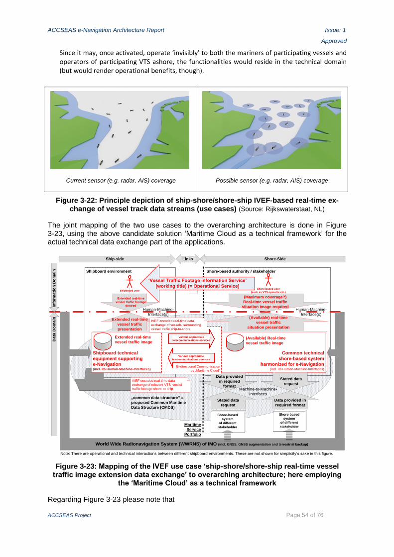
ACCSEAS e-Navigation Architecture Report Issue: 1
Approved
ACCSEAS Project Page 54 of 76
Since it may, once activated, operate ‘invisibly’ to both the mariners of participating vessels and operators of participating VTS ashore, the functionalities would reside in the technical domain (but would render operational benefits, though).
Current sensor (e.g. radar, AIS) coverage
Possible sensor (e.g. radar, AIS) coverage
Figure 3-22: Principle depiction of ship-shore/shore-ship IVEF-based real-time ex-change of vessel track data streams (use cases) (Source: Rijkswaterstaat, NL)
The joint mapping of the two use cases to the overarching architecture is done in Figure 3-23, using the above candidate solution ‘Maritime Cloud as a technical framework’ for the actual technical data exchange part of the applications.
Shipboard environment Shore-based authority / stakeholder
Shipboard userShore-based user
(such as VTS operator etc.)
Shore-based
system
of different
stakeholder
Shore-based
system
of different
stakeholder
Ship-side Links Shore-Side
Info
rma
tio
n D
om
ain
Da
ta D
om
ain
Common technical
shore-based system
harmonized for e-Navigation(incl. its Human-Machine-Interfaces)
Shipboard technical
equipment supporting
e-Navigation(incl. its Human-Machine-Interfaces)
(Available) real-time
vessel traffic
situation presentation
Extended real-time
vessel traffic footage
desired
Extended real-time
vessel traffic
presentation
(Maximum coverage?)
Real-time vessel traffic
situation image required
Stated data
request
Data provided in
required format
Data provided
in required
format
Stated data
request
Machine-to-Machine-
Interfaces
Human-Machine-
Interface(s)
Human-Machine-
Interface(s)
World Wide Radionavigation System (WWRNS) of IMO (incl. GNSS, GNSS augmentation and terrestrial backup)
„common data structure“ =
proposed Common Maritime
Data Structure (CMDS)
Functional links
used by
Technical services
Physical links
used by
Technical services
Maritime
Service
Portfolio
Note: There are operational and technical interactions between different shipboard environments. These are not shown for simplicity’s sake in this figure.
Bi-directional Communication
by „Maritime Cloud“
Various appropriate
telecommunications services
Various appropriate
telecommunications services
IVEF encoded real-time data
exchange of vessels‘ surrounding
vessel traffic ship-to-shore
IVEF encoded real-time data
exchange of relevant VTS’ vessel
traffic footage shore-to-ship
(Available) Real-time
vessel traffic image
Extended real-time
vessel traffic image
‘Vessel Traffic Footage information Service’
(working title) (= Operational Service)
Figure 3-23: Mapping of the IVEF use case ‘ship-shore/shore-ship real-time vessel traffic image extension data exchange’ to overarching architecture; here employing
the ‘Maritime Cloud’ as a technical framework
Regarding Figure 3-23 please note that

ACCSEAS e-Navigation Architecture Report Issue: 1
Approved
ACCSEAS Project Page 55 of 76
the first additional use case (i.e. the application of IVEF for the ‘Real-time VTS vessel track data stream transmission shore-ship (service)’ or shorter ‘Vessel Traffic Footage Information Service’ (working titles)) determine most of the mapping and is depicted in light red. The second addi-tional use case (‘Real-time surrounding vessel traffic footage transmission – ship-shore’ or short ‘Vessel traffic footage transmission – ship-shore’ (working titles)) is more supportive in nature and is depicted in dark red;
the shore-shore data exchange relations as introduced as the initial use case for IVEF (compare section above) and which clearly can operate simultaneously, are not shown for simplicity’s sake;
already with present telecommunication technologies data transmission ship-shore / shore-ship would be feasible for that application, sufficient bandwidth provided, however missing the com-fort and integrity features envisaged by the ‘MC’;
IMO already has recognized AIS Application Specific Messages (ASM) as a presently available means to transmit ‘VTS-generated/Synthetic targets’ in real-time and has stipulated that ‘a VTS-generated or synthetic target should only be used when the position of the target is known’ (IMO 2010, chapter 6). The ASM defined by IMO allows for MMSI, IMO Number, Call Sign, and ‘Other’ as permissible identifiers, but it does not allow for a more comprehensive vessel track footage transmission as envisaged by the IVEF use cases in this section.
3.8.5 Mapping to the generic shore architecture
As demonstrated by the previous description, the IVEF may be meaningfully employed by several use cases, which – at least in part – build on each other. As the initial use case for IVEF essentially is shore-shore, the mapping to the shore-based technical environment re-veals already the relevant, distinguishing details of this ACCSEAS candidate solution as shown in Figure 3-24.

ACCSEAS e-Navigation Architecture Report Issue: 1
Approved
ACCSEAS Project Page 56 of 76
Common Shore-based System (CSS)
Value-added Data Processing Services
Data Collection and Data Transfer services POSition
Determination Service
AIS Service
RADar Service
Traffic objects,including
ships
CSS(s) of different (peer) stakeholder(s) receiving/providing real-time vessel track stream data, using IVEF
Gateway Service
VTS Operator
UserInter-action Service
Constant real-time stream of vessels‘ dynamic data, i.e. contributions to the overall real-time vessel traffic at any point
Different services (not exhaustive) contributing to CSS‘ vessel traffic images
Real-time determination of vessels‘ positions and other dynamic data (fusion of various sensor data to consolidated vessel track)
Presentation of current vessel traffic image for e.g. VTS users ashore
Providing usual M2M interface related aspects like session control, data flow control, cybersecurity, transcoding etc.
Real-time vessel track data streams to/from other CSS(s), using IVEF
RDFService
Figure 3-24: Mapping of the IVEF-based exchange of vessel track data streams be-tween different shore-based VTS’ technical systems (= initial use case, shore-shore) to the generic CSSA
The shore-based sensor services of a CSS of a competent authority operating such a CSS, i.e. ‘Data Collection Services’ like the Radar Service (RAD), AIS Service (AIS) and Radio Direction Find-ing Service (RDF) amongst others , receive the steady stream of vessel position data in real-time and forward it to the Position Determination Service (POS) in the service group ‘Value-added Da-ta Processing Services.’ There, in real-time, ultimately the vessel track is determined, using whatever best sensor data available together with appropriate fusion and/or validation algo-rithms, if implemented. The results are then forwarded in parallel firstly towards the own User Interaction Service (UIS) to display them on an appropriate HMI for the e.g. VTS operator and secondly to the Gateway Service (GWY) where the vessel track data stream from own CSS is for-warded using the IVEF to any external CSS or technical system eligible receiving this vessel track data stream. Similarly, real-time vessel track data streams received from other CSSs are fed into the own Position Determination Service after the own Gateway Service has successfully pro-cessed the inbound data.
The re-transmission of vessel track data stream from own CSS to shipping, as required by the additional use cases of IVEF, is done using e.g. the MC technical framework. This has been mapped already in section 3.4 above. Therefore, this mapping is not reiterated here.

ACCSEAS e-Navigation Architecture Report Issue: 1
Approved
ACCSEAS Project Page 57 of 76
Similarly, any additional real-time vessel track data stream originating shipboard and received via the MC technical framework (or presently available telecommunication means via own sen-sors and/or Gateway Service ) ship-shore would be forwarded to own Position Determination Service for appropriate inclusion in its vessel traffic image calculations.
The architecture of the presentation of any real-time shore-provided vessel traffic data stream onboard participating vessels would be very similar to or even identical with the presentation of the usual radar and/or AIS real-time vessel traffic data on the appropriate HMIs at the vessel’s bridge, i.e. the generic introduction to the shipboard architecture has covered this aspect al-ready (compare section 3.1). Should the MC as a technical framework be employed to receive the shore-provided real-time vessel traffic data stream, compare the description of the resulting shipboard architecture mapping in section 3.4.3.
For further details regarding the aspirations, test-bed implementation architectures, and doc-umentation of findings of the initial test bed of and for the ACCSEAS candidate solution ‘Harmonized Data Exchange – Employing the Inter-VTS Exchange Format (IVEF)’ compare the appropriate ACCSEAS descriptions on that topic.
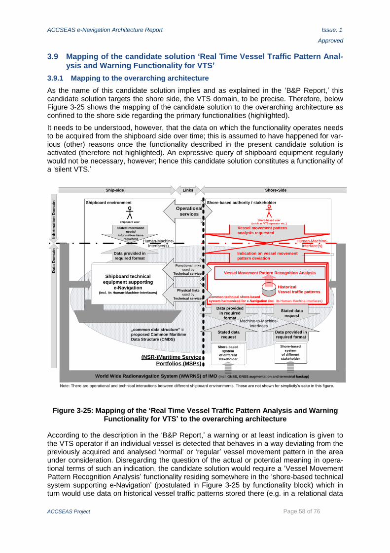
ACCSEAS e-Navigation Architecture Report Issue: 1
Approved
ACCSEAS Project Page 58 of 76
3.9 Mapping of the candidate solution ‘Real Time Vessel Traffic Pattern Anal-ysis and Warning Functionality for VTS’
3.9.1 Mapping to the overarching architecture
As the name of this candidate solution implies and as explained in the ‘B&P Report,’ this candidate solution targets the shore side, the VTS domain, to be precise. Therefore, below Figure 3-25 shows the mapping of the candidate solution to the overarching architecture as confined to the shore side regarding the primary functionalities (highlighted).
It needs to be understood, however, that the data on which the functionality operates needs to be acquired from the shipboard side over time; this is assumed to have happened for var-ious (other) reasons once the functionality described in the present candidate solution is activated (therefore not highlighted). An expressive query of shipboard equipment regularly would not be necessary, however; hence this candidate solution constitutes a functionality of a ‘silent VTS.’
Shipboard environment Shore-based authority / stakeholder
Shipboard userShore-based user
(such as VTS operator etc.)
Shore-based
system
of different
stakeholder
Shore-based
system
of different
stakeholder
Ship-side Links Shore-Side
Info
rma
tio
n D
om
ain
Da
ta D
om
ain
Common technical shore-based
system harmonized for e-Navigation (incl. its Human-Machine-Interfaces)
Shipboard technical
equipment supporting
e-Navigation(incl. its Human-Machine-Interfaces)
Stated information
needs/
information items
requested
Data provided in
required format
Operational
services
Stated data
request
Data provided in
required format
Data provided
in required
format
Stated data
request
Machine-to-Machine-
Interfaces
Human-Machine-
Interface(s)
Human-Machine-
Interface(s)
World Wide Radionavigation System (WWRNS) of IMO (incl. GNSS, GNSS augmentation and terrestrial backup)
„common data structure“ =
proposed Common Maritime
Data Structure (CMDS)
Functional links
used by
Technical services
Physical links
used by
Technical services
(NSR-)Maritime Service
Portfolios (MSPs)
Note: There are operational and technical interactions between different shipboard environments. These are not shown for simplicity’s sake in this figure.
Vessel Movement Pattern Recognition Analysis
Historical
Vessel traffic patterns
Indication on vessel movement
pattern deviation
Vessel movement pattern
analysis requested
Figure 3-25: Mapping of the ‘Real Time Vessel Traffic Pattern Analysis and Warning Functionality for VTS’ to the overarching architecture
According to the description in the ‘B&P Report,’ a warning or at least indication is given to the VTS operator if an individual vessel is detected that behaves in a way deviating from the previously acquired and analysed ‘normal’ or ‘regular’ vessel movement pattern in the area under consideration. Disregarding the question of the actual or potential meaning in opera-tional terms of such an indication, the candidate solution would require a ‘Vessel Movement Pattern Recognition Analysis’ functionality residing somewhere in the ‘shore-based technical system supporting e-Navigation’ (postulated in Figure 3-25 by functionality block) which in turn would use data on historical vessel traffic patterns stored there (e.g. in a relational data

ACCSEAS e-Navigation Architecture Report Issue: 1
Approved
ACCSEAS Project Page 59 of 76
base as indicated). Upon receiving an indication of an individual vessel’s movement pattern, the VTS operator may then query the system for more information. Also, the VTS operator may query the system out of own initiative regarding the movement pattern of any relevant vessel. Both functions are indicated by the highlighted interaction at the HMIs which needs to be designed in accordance with the format or portrayal required by the VTS operator.
3.9.2 Mapping to the generic shore architectures
When zooming to the shore-based technical environments, the details of the Real Time Vessel Traffic Pattern Analysis and Warning Functionality for VTS on both sides be-come visible, as well as a potential allocation to recognized services of the CSS (compare Figure 3-26 and the functionality distribution given in the notes to the entities).
Common Shore-based System (CSS)
Value-added Data Processing Services
Data Collection and Data Transfer services POSition
Determination Service
AIS Service
RADar Service
Traffic objects,including
ships
Shore based„third party“ users
Gateway Service
VTS Operator
UserInteraction Service
Constant stream of vessels‘ dynamic data, i.e. images of vessel traffic over time
Different services (not exhaustive) contributing to CSS‘ vessel traffic images
Data Mining Service
Determination of vessels‘ positions and other dynamic data due at present (fusion of various sensor data to consolidated vessel track)
Indication on vessel movement pattern deviation
Vessel Movement Pattern Recognition Analysis (based on historical vessel traffic patterns)
Figure 3-26: Mapping of the Real Time Vessel Traffic Pattern Analysis and Warning Functionality for VTS to the generic CSSA
Notes:
In particular the functionality central to this candidate solution, namely the ‘Vessel Movement Pattern Recognition Analysis’ always should reside in the group of ‘Value-added Data Processing Services,’ because that is what this functionality does in every regard of that term. However, the specific service to allocate the functionality at best may be the ‘Position Determination Service (POS)’. The ‘Data Mining Service’ comes into consideration because the vessel movement pat-

ACCSEAS e-Navigation Architecture Report Issue: 1
Approved
ACCSEAS Project Page 60 of 76
tern recognition can be construed as a ‘data mining’ functionality because it needs a wealth of historical data to function properly, i.e. a feature which discriminates the Data Mining Service from the POS.
As with other candidate solutions, a secondary usage of the analysis data (i.e. of an ‘indication’) may be to forward it via the ‘Gateway Service,’ i.e. by one of its M2M as appropriate, to an ex-ternal user’s system (not highlighted).
ACCSEAS e-Navigation Architecture Report Issue: 1
Approved
ACCSEAS Project Page 61 of 76
4 Conclusions from architectural mapping of ACCSEAS candidate solutions
Based on the general definition of ‘architecture’ and the fundamental notion, that different architectural perspectives are required to provide a full picture, several different architectural perspectives were introduced.
‘Mapping’ means ‘showing how it is supportive’ to the different architectural perspectives at hand. Hence, when mapping candidate solutions to the different architectural perspectives as done in the above sections, it is demonstrated not only that the candidate solutions have a place in those different architectural perspectives, but in what regards the candidate solu-tions support the architectural perspective at hand.
4.1 Conclusions regarding mapping to the internationally recognised archi-tectures for e-Navigation
The previous sections with their mapping of the various candidate solutions to the different architectural levels, namely to the IMO adopted overarching architecture for e-Navigation as well as to a generic shipboard (INS-centric) and shore-based architecture (CSSA), as ap-propriate, prompt the following conclusions:
Architectural or ontological mapping is feasible
- with all candidate solutions investigated here;10
- with the wide scope of different ontological qualities they exhibit individually;
- with the external stipulations imposed (e.g. from IMO e-Navigation) and the methods ap-plied,
- with a meaningful result each, i.e. at least one starting point for further operational and/or technical exploration and research or even NSR implementation suggestions in no un-precise terms.
This prove of feasibility in itself carries a two-fold success in regards to the architectural or onto-logical analysis stipulated to be performed by this Report, namely
- the target architectures are ‘working’ and therefore can be considered ‘correct’ to the extent of what they want to show at their respective levels of detail;
- the candidate solution can be considered as ‘solid in architectural terms to the degree of de-tail investigated’ each.
This holds true even though the above architectural or ontological analysis, on the detailed levels of the generic shipboard and generic shore-based architectures, presented only one option to allocate the functionality to a specific generic entity of those architectures: Although the allocation presented in the above appears to be a ‘best practice’ each, there may be oth-er allocation options. This, however, does not contradict the above conclusions; it just intro-duces a certain degree of permissible variance and also identifies the starting point for fur-ther research, both in operational as well as technical terms.
In addition, the above architectural or ontological mapping also identified in precise architec-tural terms ‘unexplored territory,’ namely where there are assumptions made or postulates stated. Further studies are needed to explore this ‘unexplored territory.’
10 Unfortunately, not all candidate solutions could be investigated here with the same depth of analysis. This is solely due to ACCSEAS project resource limitations.

ACCSEAS e-Navigation Architecture Report Issue: 1
Approved
ACCSEAS Project Page 62 of 76
The above analyses started to reveal a certain degree of intricacies of both the operational and technical processes involved:
The operational processes incurred a need to be – ideally – fully understood by the mariners and/or shore-based operators involved.
While candidate solutions like the MC aim at deliberately encapsulating the technical intricacies involved, still, at least a certain general understanding for the processes encapsulated, their de-sired deliverables as well as typical malfunction conditions should be obtained by the mariners and by the shore-based operators – the above analyses may assist here.
This seems to prompt certain training needs with the educational goal for the operational train-ees to understand
- the operational processes holistically and in the required functional detail,
- the supporting technical processes, which are otherwise encapsulated or ‘invisible’ to opera-tors, still holistically, but only generally, however with their desired outcomes and delivera-bles as well as typical malfunction conditions in the required detail, again.
4.2 Conclusions regarding specific support for EU initiatives
ACCSEAS is supposed to deliver support for EU initiatives. The ‘B&P Report’ (ACCSEAS 2015), Chapter 3, already analysed and described ACCSEAS’ wider context regarding Eu-ropean developments. Here, the focus is more on the specific contribution of ACCSEAS candidate solutions to EU initiatives, as far as investigated by ACCSEAS and as far as ap-plicable. This potential specific support of the ACCSEAS candidate solutions is given here in their order of appearance as introduced above. Please note, that the following identifications are not meant to be exhaustive in any way.
- Maritime Service Portfolios (MSPs) for the NSR (NSR-MSPs): A NSR-MSPs, once established, may directly support the EU Maritime Transport Policy (including the e-Maritime initiative) as there was made reference to the future implementation of certain ‘e-Services,’ to be defined in due course, as part of this initiative; compare (ACCSEAS 2011, A.8.1).
- Route Topology Model (RTM): The NSR-RTM, once established, may directly support in particular the EU Motorways of the Seas (TEN-T), the EU INSPIRE (Module Transport Networks), and the Marine Spatial Planning (MSP) initiatives, amongst others. Compare the more detailed explora-tion in the ‘ACCSEAS RTM Description’ report.
- ‘Maritime Cloud (MC)’ as an underlying technical framework solution: The NSR implementation of the ‘MC,’ once established, may qualify as a contributing set of technical services to the above NSR-MSPs.
- Innovative Architecture for Ship Positioning comprising both Multi Source Positioning Service and R-Mode at existing MF DGNSS and AIS Services: The NSR implementation of the shore-based ser-vices implied by that architecture, once established, may qualify as a contributing set of tech-nical services to the above NSR-MSPs (‘Resilient PNT Provision’). In addition, these ACCSEAS can-didate solutions may directly support a future edition of an European Radio Navigation Plan/Strategy, including terrestrial radio navigation.
- Maritime Safety Information/Notices to Mariners (MSI/NM) Service, No-Go-Area Service, and Tactical Route Suggestion Service (shore-ship): The NSR implementation of the ‘MSI/NM Service,’ once established, may qualify as operational services contributing directly to the above NSR-MSPs or indirectly supporting them (as in the case of the Tactical Exchange of Intended Route (ship-ship and ship-shore)).
ACCSEAS e-Navigation Architecture Report Issue: 1
Approved
ACCSEAS Project Page 63 of 76
- Vessel Operation Coordination Tool (VOCT): The NSR implementation of the ‘VOCT,’ once estab-lished, may qualify as a contributing set of operational and technical services to the above NSR-MSPs.
- Automated FAL Reporting: This ACCSEAS candidate solution, once fully explored and established in the NSR, may assist the EU initiative on ‘National Single Windows’ and thereby support the EU Maritime Transport Policy (including the e-Maritime initiative).
- Harmonized Data Exchange – Employing the Inter-VTS Exchange Format (IVEF): The shore-based Inter-VTS data exchange part of this ACCSEAS candidate solution, once established around the NSR, may support the EU Maritime Transport Policy (including the e-Maritime initiative). In addi-tion, the Inter-VTS Exchange Format, once revised and more fully developed, may provide an in-ternationally harmonised means to exchange data between the vessel traffic domain, ports and other transportation domains, even in real-time, and thus may serve as a contribution to the en-visaged data interfaces between those modes of transportation, for example as envisaged by the EU ITS initiative from their land transportation point of view. In addition, the vessel footage ex-tension part of this ACCSEAS candidate solution, once established, may qualify as a contributing set of operational and technical services to the above NSR-MSPs.
4.3 Final summary conclusion
The very demonstration of the existence of a specific role of ACCSEAS, as a regional Euro-pean project for the NSR, within the relevant international and European frameworks in itself is a strong architectural statement.
This in turn can serve to summarised the above conclusion as follows:
There is a lasting wealth of ACCSEAS regarding the transformation of the international SMTS and e-Navigation strategies into their appropriate NSR implementations.
From an architectural perspective, some of the ACCSEAS candidate solutions are demon-strated mature enough to be seriously considered for actual operational implementation in the NSR in the near to intermediate future as a legacy of ACCSEAS.
Other ACCSEAS candidate solutions require further analysis and exploration in due course.

ACCSEAS e-Navigation Architecture Report Issue: 1
Approved
ACCSEAS Project Page 64 of 76
This page is deliberately blank.

ACCSEAS e-Navigation Architecture Report Issue: 1
Approved
ACCSEAS Project Page 65 of 76
5 Design Techniques
This final Chapter now fulfils the stipulation of the ACCSEAS Application (ACCSEAS 2011) on ‘design techniques.’ Within ACCSEAS, there are two major relevant aspects to this, namely the system engineering techniques employed and the use of simulations within simu-lators. Both aspects will be discussed in a dedicated section each.
5.1 Systems engineering techniques employed
ACCSEAS employs a system engineering approach. The main aim of the discipline of Sys-tems Engineering (Stevens et al 1998) is to enable engineers to cope with projects and de-velopments of any complexity. System engineering is about creating effective solutions to problems, and managing the technical complexity of the resulting developments. At the out-set it defines the requirements and therefore the product to be built. The emphasis then switches to implementation, integration and verification (testing) before delivering the final resulting system to the customer. A two-step approach is used to arrive at system require-ments which in turn are needed to design and implement the desired system.
5.1.1 The Derivation Chain from User Requirements to System Requirements
User requirements are the first step in defining a system. Every system needs to satisfy its users and/or stakeholder(s) to be successful; so it must be defined who they are and what they want. In the case of ACCSEAS, there are actually a number of users and/or stakehold-er(s) (compare Table with IMO recognized users at section on ‘IMO e-Navigation Strategy’ in ‘B&P Report’). Systems engineering must handle the whole life cycle; at times trading off between competing factors such as performance, risk and cost. Systems engineering must ensure that designs are practicable and meet user requirements. A holistic approach is needed without bias toward specific sub-systems or technology.
Capturing and organizing requirements is a vital system engineering task. User requirements should act as the reference point for what users need; requirements are the foundation for any product – cars, aircraft, bridges, buildings, legislation, and of course e-Navigation test-beds. Early work is required in user requirement capture in order to ensure results later on in the project. Systems engineering provides the framework for the work of all other engineer-ing disciplines, remaining discipline and product independent. Close communication and co-ordination across disparate groups is required. Central to the discipline of systems engineer-ing is the System Life Cycle as shown in Figure 5-1.
Figure 5-1: Systems engineering life cycle.
This model consists of a sequence of processes from user requirements, through system requirements, architectural design and component development to the testing cycle of inte-gration, installation and operations. At each process boundary a review or test allows the progress to be monitored and a commitment made to the next stage. These boundaries act as quality milestones, controlling the gradual transformation from a high risk idea to a com-plete concrete product. The life cycle defines the order in which information must be pro-duced, and the users, developers and designers each have the responsibility for separate parts of the information. Each component is developed as an entity, fitting within the overall

ACCSEAS e-Navigation Architecture Report Issue: 1
Approved
ACCSEAS Project Page 66 of 76
design framework. The components are then integrated into a complete system, which can be transferred to the working environment.
Figure 5-2 shows how the ACCSEAS WPs map to the stages of the systems engineering life cycle, illustrating that from the ground up ACCSEAS has been designed to take advantage of the complexity handling abilities of the systems engineering process.
Figure 5-2: Mapping the ACCSEAS WPs to the Systems Engineering life-cycle.
Figure 5-3 shows a V-diagram. This is another view of the life cycle. The left hand side of the diagram defines what must be built, and the right hand side builds it from the components, and verifies the end products against the left hand specification. Information produced to specify components is the basis of testing those components during the integration stage.
Figure 5-3: V-diagram form of systems engineering life cycle.
Verification is concerned about ensuring that we are building the system correctly, while val-idation is concerned about ensuring that we are building the correct system.
5.1.2 The NSR Vessel Traffic Situation and the IMO User Needs informing ACCSEAS
The first step in the systems engineering process is the determination of user requirements which must be informed by the user needs (compare Figure 5-4 and appropriate Chapter of ‘B&P Report’):

ACCSEAS e-Navigation Architecture Report Issue: 1
Approved
ACCSEAS Project Page 67 of 76
Figure 5-4: ACCSEAS Two Level User Requirements gathering process
Firstly, it is the analysis of the present and future vessel traffic situation of the NSR, as repre-sented in the ACCSEAS Geographical Information System (GIS) that contributes to the derivation of high level user requirements: It is the reduction of sea space and thus the reduction of ma-neuverability and the associated increase in congestion that prompts certain user requirements. I.e. this is an analysis at the highest level of abstraction regarding user requirements in the scope of ACCSEAS.
Secondly, IMO has stated that e-Navigation should be based on the recognized user needs of both shipboard and shore-based users. In the ‘B&P Report,’ the IMO recognized users, both on the shipboard side and the shore side, and their respective user needs were given. IMO has de-rived certain ‘solutions’ and ‘tasks’ from those user needs, and it can be safely assumed that the IMO derived ‘tasks’ create the IMO desired ‘solutions’ which in turn satisfy the IMO recognized ‘user needs’ because this derivation process underwent an extensive validation at IMO.
ACCSEAS, by means of the candidate solutions, supports a certain subset of the IMO identi-fied ‘tasks’ and thereby indirectly the fulfillment of a certain subset of IMO identified user needs as follows: Due to the inherent restrictions of a project, the scope of ACCSEAS need-ed to be limited. This was achieved by the selection of the candidate solutions. The candi-date solutions have been demonstrated in Chapter 2 above to be specifically supportive of

ACCSEAS e-Navigation Architecture Report Issue: 1
Approved
ACCSEAS Project Page 68 of 76
certain IMO SIP defined ‘tasks’ and thereby of ‘solutions’ and thereby of ‘user needs’ as demonstrated in the previous paragraph.
The candidate solutions represent low level user requirements.
It should be noted that the above process has rendered user requirements of as well as candidate solutions which are relevant to both shipboard and shore-based users.
5.1.3 From user requirements to system requirements
The next stage following on from user requirements is the development of system require-ments. User and system requirements are very different in their nature and organization. The former defines the results of the system that the users will see and are short and non-technical, while the latter impose requirements (constraints) on an abstract model of the sys-tem to be implemented and are evolved from user Requirements. System requirements de-fine what the system must do to be able to meet the user requirements; they are the devel-oper’s response to the user requirements and are usually too large and technical for users to understand.
System requirements explore the solution, but avoid commitment to any specific design. They define what the system will do, but not how.
In ACCSEAS, the derivation of the set of test-bed system requirements from user require-ments was done in subsequent WPs 4, 5 and 6. In order to provide the identified candidate solutions at the test-bed locations, any gaps in the system requirements were determined. System requirements again were split into ‘high level’ (i.e. ports, vessels, PNT coverage etc.) and ‘low level’ (power supply, data communications, antenna mounts etc.). ACCSEAS test-bed design was then based on the identified system requirements.
It should be noted that some candidate solutions are applicable everywhere, uniformly throughout the NSR, e.g. the Maritime Safety Information/Notices to Mariners (MSI/NM) Service, while other candidate solutions may only be applicable along various routes and at various nodes and junctions like the No-Go-Area Service, the Tactical Route Suggestion Service (shore-ship) and the Tactical Exchange of Intended Route (ship-ship and ship-shore).
5.2 Simulation architectures
In the ‘B&P Report’ the use of simulation and simulators was introduced as an important tool for ACCSEAS to evaluate the candidate solutions at their HMIs, as far as possible.
The general architectural aspects of the use of simulation and simulators within the AC-CSEAS are described here. The use of simulators in ACCSEAS is described using mainly the example of the ship handling simulation facilities of Flensburg University of Applied Sci-ences (FUAS), Germany. The simulation environments of other ACCSEAS partners with ship handling simulators are similar.
By using ship handling simulation environments, the shipboard HMI to the mariner(s) was evaluated; for the simulation of the HMI of a candidate solution to a HMI to a shore-based user, e.g. a VTS operator, a VTS simulator were required and employed.
For further details refer to the ‘ACCSEAS Use of Simulators in e-Navigation Training and Demonstration Report.’
5.2.1 General architecture of a ship handling simulation environment
The facilities of the maritime centre of FUAS consist of several navigational simulators, com-puter-based training environments an electronic self-study/self-exercising provisions in more than 20 seminar rooms and laboratory premises.

ACCSEAS e-Navigation Architecture Report Issue: 1
Approved
ACCSEAS Project Page 69 of 76
The Full-Mission Ship Handling Simulator (SHS) used in ACCSEAS comprises six fully equipped navigational bridges with 1x 330°, 2x 210° and 3x 120° visual systems (Figure 5-5). The simulator can be operated and monitored by three independent instructor stations. Additionally, four workstations are used for the development of realistic hydrographic and topographic simulation scenarios, sea areas and ship models.
Figure 5-5: Example of a ship handling simulator environment overview (FUAS)
To establish and ensure realistic testing environments for candidate solutions, the Bridge No. 1 of the Full-Mission SHS was equipped with a state-of-the-art Integrated Bridge System (IBS) with four built-in multifunctional INS. The whole bridge environment fully complies with the latest IMO performance standards in regard to Radar, ECDIS, Conning, INS and others.
5.2.2 Implementation of Resilient PNT for simulator tests
The standard data structure of an IBS is shown in Figure 5-6. Due to redundancy all naviga-tional data provided by sensors is transmitted via manufacturer specific Ethernet LAN and NMEA Protocol (RS422) interface. This architecture makes every multifunctional navigation-al station (Radar, ECDIS, Conning …) independent from other stations and their status or availability. In the simulator environment the data is generated by simulation software and broadcasted to the IBS via Ethernet LAN only (for simplification reasons).

ACCSEAS e-Navigation Architecture Report Issue: 1
Approved
ACCSEAS Project Page 70 of 76
Figure 5-6: IBS data flow structure
To implement PNT for test purposes of candidate solutions like Resilient PNT the simulation generated data flow towards the IBS has to be interrupted and filtered: PNT-data like posi-tioning, ROT and other shipboard data has to be separated from non-PNT data. The former will be diverged and introduced into the PNT test module for processing. The generated out-put has to be introduced back in the IBS for usage in the navigational stations. Other data calculated for the Resilient PNT solution like accuracy, alarms and quality prioritization will be presented in an external visualization station to compare the raw data outputs with its IBS usage. See Figure 5-7 for details. This test architecture for Resilient PNT provides the following possibilities and potentials:
General PNT usage feasibility in IBS (and INS);
PNT tests in test bed. Therefore test bed scenario/area has to be developed for simulator appli-cation;
Comparison of raw PNT output data with IBS user visualization;

ACCSEAS e-Navigation Architecture Report Issue: 1
Approved
ACCSEAS Project Page 71 of 76
Verification of user-friendliness of PNT data inside IBS (HMI);
Evaluation of training needs.
Figure 5-7: Data flow architecture for Resilient PNT tests
5.2.3 Test of candidate solutions other than Resilient PNT
Simulator Bridge No. 1 and its established visualization and comparison station can be used for the simulation of a variety of candidate solutions besides Resilient PNT. Due to the avail-ability of the bathymetric, hydrographic and topographic test bed data shore based technical or operational services as described by the MSPs and provided to the ship bridges can be tested during running scenarios with fully manned bridge personnel.
Reduced manoeuvring area due to rapidly growing wind farm installations in heavy traffic regions requires additional information and support measures for the shipboard bridge oper-ators. The present or future off-shore wind parks situation in the simulated sea area will be presented during the test runs. To that end, additional layers in ECDIS with offshore wind-farm relevant data have been implemented, which – together with traffic significant data – provide collision avoidance decision support for bridge personnel. Thus, full offshore wind-farm visualization is achieved to verify the benefits of the candidate solution under test to the ships command under ‘wind mill city’ sailing conditions.
5.2.4 Simulator tests to consider training aspects
The situation in maritime transportation in 2020+ will be characterised by a number of new applications installed in shore-based stations and on-board ships’ navigational bridges. New

ACCSEAS e-Navigation Architecture Report Issue: 1
Approved
ACCSEAS Project Page 72 of 76
technologies and procedures are expected to be introduced and they need to be reliably and safely used by the mariners. The candidate solutions may be construed as a vanguard of those new technologies and procedures.
The potential impact of the candidate solutions on training needs to be determined, too. In ACCSEAS, the training needs and gaps of the candidate solutions are determined, but also how maritime training is potentially influenced by new developments due to the implementa-tion of e-Navigation at large.
As a case study, a dynamic prediction has been studied in the context of the macro- and micro- aspects of ships voyage planning process. For that, a simulator configuration as de-picted in the Figure 5-8 was used.
Figure 5-8: Simulator configuration to study training needs regarding use of dynamic predictions (configuration of WMU-MaRiSa-Sim-Lab)
Planning Station with
dynamic prediction feature

ACCSEAS e-Navigation Architecture Report Issue: 1
Approved
ACCSEAS Project Page 73 of 76
6 Abbreviations
ACCSEAS – ACCessibility for Shipping, Efficien-cy Advantages and Sustainability
AIS – Automatic Identification System
AIS Service – a shore-based service (part of CSSA) to allow e.g. VTS authorities to par-ticipate in the AIS.
API – Application Interface, i.e. an M2M pre-sented by an application software module to other software modules.
AR – Augmented Reality
ARPA – Advanced Radar Plotting Aid; ship-board radar functionality
ASM – Application Specific Messages (of the AIS) the international branch of which is defined in part by (IMO 2010).
B&P Report – ‘ACCSEAS Baseline & Priorities Report; Edition 3;’ compare [3]
CCRS – Consistent Common Reference System, being an integral part of the shipboard INS
CSS – Common Shore-based System; technical description of which is presently under preparation at IALA
CSSA – Common Shore-based System Archi-tecture; architecture of the CSS.
DGN – DGNSS Correction Service (of the CSSA); a shore-based technical service which provides RTCM encoded DGNSS corrections for D-Mode.
D-Mode – capability of a system to process Differential-GNSS data.
ECDIS – Electronic Chart and Display System; shipboard system to display ENCs, amongst other data.
ENC – Electronic Navigational Chart
EU – European Union
ETA – Estimated Time of Arrival
FAL – Facilitation (Convention, Committee, Form, …) of IMO
GIS – Geographical Information System
GMDSS – Global Maritime Distress and Safety System
GNSS – Global Navigation Satellite System
HAL – Horizontal Alert Limit (within Resilient PNT)
HMI – Human Machine Interface
HPL – Horizontal Protection Limit (within Re-silient PNT)
HUD – Head-Up Display
IALA – International Association of Marine Aids to Navigation and Lighthouse Authori-ties, St-Germain-en-Laye, France.
IBS – Integrated Bridge System
IGO – Inter-governmental organization
IHO – International Hydrographic Organisa-tion, Monaco; an inter-governmental or-ganisation.
IMO – International Maritime Organisation, London, UK; ‘the UN Specialized Agency responsible for setting global standards for safe, secure, clean and efficient maritime transport’ (IMO-SG 2013, p. 5).
INS – Information Service (of VTS)
INS – Integrated Navigation System (ship-board)
IRC – Integrated Radio Communication
IRCS – Integrated Radio Communication Sys-tem
ITIL – IT Infrastructure Library
ITS – Intelligent Transportation Systems
ITU – International Telecommunications Un-ion, Geneva, Switzerland; a specialized or-ganisation in the United Nation system.
IVEF – Inter-VTS Exchange Format
M2M – Machine-to-Machine interface
MC – Maritime Cloud
MCCC – Maritime Cloud Client Component
MF DGNSS Service – Medium-Frequency Dif-ferential Global Navigation Satellite Ser-vice; a shore-based terrestrial augmenta-tion system which is internationally stand-
ACCSEAS e-Navigation Architecture Report Issue: 1
Approved
ACCSEAS Project Page 74 of 76
ardized by IALA und uses MF signals for DGNSS correction data broadcast.
MI – Maritime Identity
MIM – Maritime Information Message; a pro-posed term which includes MSI and NM and other information and implies that the MIM are being broadcast in a consistent manner.
MIR – Maritime Identity Registry
MMS – Maritime Messaging Service (of the CSSA)
MPR – Maritime Portfolio Registry Service (of the CSSA)
MRCC – Maritime Rescue and Coordination Centre
MSI – Maritime Safety Information
MSP – Marine Spatial Planning
MSP – Maritime Service Portfolio (singular; a single one within the framework of MSPs)
MSPS – Multi-Source Positioning Service
MSPs – Maritime Service Portfolios; an over-arching concept under international devel-opment in the context of e-Navigation.
NGO – non-governmental organisation
NM – Notices to Mariners
NSR – North Sea Region as defined by the EU.
NSR-MSPs – Maritime Service Portfolios for the North Sea Region, i.e. definition of an instance of MSPs for the NSR.
NSR-RTM – Route Topology Model for the North Sea Region, i.e. definition of an in-stance of RTM for the NSR
PNT – Position, Navigation, Timing
POS – Position Determination Service (of the CSSA)
RAD – Radar Service (of the CSSA)
RCO – Risk Control Option; part of the Formal Safety Assessment methodology
RDF – Radio Direction Finding Service (of the CSSA)
R-Mode – Ranging Mode; a method which could be applied, in principle, to any radio signal to determine the range between the emitter of the radio signal and the recipi-ent by determining the duration of time between Time-of-Emission (TOE) and Time-of-Arrival (TOA) at the recipient.
Rio+20 – UN Conference on Sustainable De-velopment, Rio de Janeiro, 2012. The pro-cess ensuing from the conference also is called ‘Rio+20.’
RRM – Radio Resource Management
RTCM – Radio Technical Commission Mari-time; a US standardization body
RTM – Route Topology Model
SAR – Search and Rescue
S – Solution (as identified by the SIP)
SG – Secretary General
SIP – IMO e-Navigation Strategy Implementa-tion Plan; compare (IMO 2014).
SMTS – Sustainable Maritime Transportation System; proposed by the IMO Secretary General, Mr. Koji Sekimizu; compare (IMO-SG 2013).
UTC – Universal Time Coordinated
VOCT – Vessel Operation and Coordination Tool
VTS – Vessel Traffic Services
WMU – World Maritime University, Malmö, Sweden, a university of the IMO
WP – Work Package of ACCSEAS; compare (ACCSEAS 2011) for a complete list and de-scription of ACCSEAS WPs
WWRNS – World-Wide Radio Navigation Sys-tem (of IMO)
XML – Extended Markup Language.

ACCSEAS e-Navigation Architecture Report Issue: 1
Approved
ACCSEAS Project Page 75 of 76
7 References
ACCSEAS. 2011. The Interreg IVB North Sea Region Programme, Application Form 8th Call. ACCessibility for Shipping, Efficiency Advantages and Sustainability (ACCSEAS). Submitted 30 September 2011, approved by Grant Contract between Managing Au-thority of the North Sea Region Programme 2007-2013 represented by the Central Denmark Region and Trinity House (on behalf of the General Lighthouse Authorities of UK and Ireland) as Lead Beneficiary of the project, 28th June 2012, Journal-ID: 35-2-25-11.
ACCSEAS. 2015. ACCSEAS Project. ACCSEAS Baseline and Priorities Report. Revised and Updated Edition 3. London.
IALA. 2011. IALA Recommendation V-145 on the Inter-VTS Exchange Format (IVEF) Ser-vice. Edition 1. June 2011. St-Germain-en-Laye, France.
IALA. 2015 (a). Draft Revision of IALA Recommendation e-NAV 140 on the Architecture for Shore Based Infrastructure ‘fit for e-Navigation’, ENAV16-14.1.11, April 2015. This
document was approved by IALA ENAV Committee in April 2015 and is awaiting adoption by IALA Council at the point of writing of this report.
IALA. 2015 (b). Draft IALA Guideline on Design and Implementation Principles for Harmo-nized System Architecture of Shore Based Infrastructure, ENAV16-14.1.6, April 2015. This document was approved by IALA ENAV Committee in April 2015 and is awaiting adoption
by IALA Council at the point of writing of this report.
IALA. 2015 (c). Draft IALA Guideline on the IALA Common Shore-based System Architec-ture CSSA, ENAV16-14.1.12, April 2015. This document was approved by IALA ENAV
Committee in April 2015 and is awaiting adoption by IALA Council at the point of writing of this report.
IMO. 1995. Performance Standards for a shipborne Integrated Radiocommunication System (IRCS) when Used in the GMDSS. Assembly Resolution A.811(19), adopted 23. November 1995. London: IMO.
IMO. 2009. ‘Strategy for the Development and Implementation of e-Navigation.’ In: IMO Mar-itime Safety Committee. Report of the Maritime Safety Committee on its 85th Ses-sion. MSC 85/26/Add.1, Annex 20, 6 January 2009. London.
IMO. 2010. Guidance on the Use of AIS Application Specific Messages. SN.1/Circ.289. 2 June 2010. London.
IMO. 2014. ‘Draft IMO e-Navigation Strategy Implementation Plan (SIP).’ In: IMO Sub-Committee on Navigation, Communication and Search and Rescue. Report to the Maritime Safety Committee. NCSR 1/28, Annex 7. 16 July 2014. London. Adopted by IMO MSC 94, 17-21 November 2014.
IMO-SG. 2013. The Secretary-General of IMO, Mr Koji Sekimizu. A Concept of a Sustaina-ble Maritime Transportation System. (Sustainable Development: IMO’s Contribution beyond Rio+20) London: IMO. September 2013 (World Maritime Day).
ITU. 2014. Recommendation ITU-R M.1371-5 (02/2014). Technical characteristics for an automatic identification system using time division multiple access in the VHF mari-time mobile frequency band. Geneva.
Norway. 2012. Development of an e-Navigation Strategy Implementation Plan. Report from the Correspondence Group on e-navigation to NAV 58. NAV58/6. 30 March 2012. London: IMO.
Office of Government Commerce. 2007. ITIL Service Strategy. Second impression with cor-rections. Norwich: The Stationary Office.

ACCSEAS e-Navigation Architecture Report Issue: 1
Approved
ACCSEAS Project Page 76 of 76
Stevens, Brook, Jackson and Arnold. 1998. Systems Engineering – Coping with Complexity. Prentice Hall, 1998, ISBN: 978-0-13-095085-7.
Wikipedia. 2014. ‘Systems architecture.’ URL: EN.Wikipedia.org. Access: 11th September 2014.