AC Long Template (1-1 autonum)
197
U.S. Department of Transportation Federal Aviation Administration Advisory Circular Subject: Oceanic and International Operations Date: 8/12/10 Initiated by: AFS-400 AC No: 91-70A Change: FOREWORD This advisory circular (AC) contains general information and guidance for operators planning oceanic flights, including authorizations needed for operations outside the continental United States. This includes Special Areas of Operation (SAO) such as North Atlantic Minimum Navigation Performance Specifications (NAT/MNPS), Reduced Vertical Separation Minimum (RVSM), Area Navigation (RNAV), and Required Navigation Performance (RNP) airspace. The dynamics of oceanic operations are such that they are constantly evolving and it is incumbent on the operators to closely monitor any changes. The Federal Aviation Administration (FAA) revised this AC to point the reader to the most current sources of international material. In many cases, the references are to a Web site. The material, however, is still found at www.faa.gov or calling a Federal Aviation Administration (FAA) navigation specialist. This AC includes specific guidance for authorizations and other FAA policy issues. A detailed study of the FAA Web site is the best source for introduction information about oceanic, international, and remote operations. John M. Allen Director, Flight Standards Service Downloaded from http://www.everyspec.com
Transcript of AC Long Template (1-1 autonum)
U.S. Department of Transportation Federal Aviation Administration
Advisory Circular
Subject: Oceanic and International Operations
Date: 8/12/10 Initiated by: AFS-400
AC No: 91-70A Change:
FOREWORD
This advisory circular (AC) contains general information and guidance for operators planning oceanic flights, including authorizations needed for operations outside the continental United States. This includes Special Areas of Operation (SAO) such as North Atlantic Minimum Navigation Performance Specifications (NAT/MNPS), Reduced Vertical Separation Minimum (RVSM), Area Navigation (RNAV), and Required Navigation Performance (RNP) airspace. The dynamics of oceanic operations are such that they are constantly evolving and it is incumbent on the operators to closely monitor any changes. The Federal Aviation Administration (FAA) revised this AC to point the reader to the most current sources of international material. In many cases, the references are to a Web site. The material, however, is still found at www.faa.gov or calling a Federal Aviation Administration (FAA) navigation specialist. This AC includes specific guidance for authorizations and other FAA policy issues. A detailed study of the FAA Web site is the best source for introduction information about oceanic, international, and remote operations.
John M. Allen Director, Flight Standards Service
Downloaded from http://www.everyspec.com

AC 91-70A 8/12/10
CONTENTS
Paragraph Page
CHAPTER 1. GENERAL
1-1. Purpose...........................................................................................................................1 1-2. Cancellation ...................................................................................................................1 1-3. Applicability ..................................................................................................................1 1-4. Related CFR Regulations (current editions) ..................................................................1 1-5. Background....................................................................................................................2 1-6. General Information.......................................................................................................2
CHAPTER 2. UNITED STATES AVIATION AND THE ICAO
2-1. Background....................................................................................................................5 2-2. ICAO and the ICAO Annexes .......................................................................................5 2-3. U. S. Public Law, International Agreements, and Standards Related to Air
Navigation......................................................................................................................9
CHAPTER 3. OCEANIC, INTERNATIONAL, AND REMOTE OPERATIONS
3-1. Introduction..................................................................................................................11 3-2. Equipment ....................................................................................................................18 3-3. ATC..............................................................................................................................22 3-4. Oceanic Communications ............................................................................................26 3-5. Navigation Procedures (Navigation Sensors—Inertial Navigation System (INS),
Inertial Reference Systems (IRS), or GNSS)...............................................................27 3-6. Position Plotting...........................................................................................................28 3-7. Oceanic Operations......................................................................................................38 3-8. Extended Operations (ETOPS) ....................................................................................38 3-9. Strategic Lateral Offsets in Oceanic Airspace to Mitigate Collision Risk and Wake
Turbulence ...................................................................................................................39 3-10. Oceanic Emergency Procedures ..................................................................................40 3-11. Communication, Navigation, Surveillance, and Air Traffic Management
(CNS/ATM) Technology.............................................................................................44 Figure 1. Data Link Diagram...................................................................................................45 3-12. Monitoring of Performance-Based Navigation (PBN) and Communication...............46
CHAPTER 4. ATLANTIC, CANADA, AND EUROPEAN OPERATIONS
4-1. Atlantic Region ............................................................................................................49 4-2. Communications ..........................................................................................................50 4-3. Navigation....................................................................................................................50 4-4. Surveillance—Canadian Control Areas.......................................................................51 Figure 2. Canada—Northern, Southern and Arctic Control Areas..........................................51 4-5. European Region..........................................................................................................52
Page ii
Downloaded from http://www.everyspec.com

8/12/10 AC 91-70A
Page iii
CONTENTS (continued)
Paragraph Page
CHAPTER 5. NORTH PACIFIC OCEANIC OPERATIONS
5-1. Introduction..................................................................................................................55 5-2. Communications ..........................................................................................................55 5-3. Navigation....................................................................................................................57 5-4. Surveillance..................................................................................................................58 Figure 3. Pacific Organized Track System Routes ..................................................................59 Figure 4. North Pacific Routes.................................................................................................60 5-5. Class II Navigation and Position Planning ..................................................................61
CHAPTER 6. SOUTHERN PACIFIC OCEANIC OPERATIONS
6-1. Introduciton..................................................................................................................63 6-2. Communications ..........................................................................................................63 6-3. In-Flight Contingencies. ..............................................................................................64
CHAPTER 7. WATRS/CARIBBEAN OPERATIONS
7-1. General.........................................................................................................................65 7-2. Operational Policy and Procedures..............................................................................65 7-3. Navigation....................................................................................................................70 Figure 5. West Atlantic Route System Plus Oceanic Airspace ...............................................76
CHAPTER 8. SOUTH AMERICA AND THE CARIBBEAN
8-1. Introduction..................................................................................................................77 8-2. Navigation....................................................................................................................77 8-3. Communications ..........................................................................................................77 Figure 6. In-Flight Broadcast Procedures Over Intertropical Convergence Zone ...................79 8-4. Collision Avoidance.....................................................................................................82 8-5. Dispatch .......................................................................................................................82 Figure 7. Aircraft Communications Addressing and Reporting System Gap..........................82 8-6. Maintenance/Dispatch Criteria ....................................................................................83 8-7. Emergency Procedures and Diversions .......................................................................83 8-8. Medical Diversion........................................................................................................85 8-9. Depressurization Procedures........................................................................................86 8-10. Safety of Flight ............................................................................................................86 Figure 8. Terrain Critical Areas ...............................................................................................86 8-11. Central America and Caribbean Weather ....................................................................88 8-12. South America Weather Information...........................................................................92 8-13. Communication............................................................................................................96 8-14. Navigation....................................................................................................................96 8-15. Surveillance..................................................................................................................96
Downloaded from http://www.everyspec.com

AC 91-70A 8/12/10
CONTENTS (continued)
Paragraph Page
8-16. CAR-SAM Routes .......................................................................................................97 Figure 9. Miami to Sao Paulo ..................................................................................................97
CHAPTER 9. GULF OF MEXICO OPERATIONS
9-1 Introduction................................................................................................................105 9-2. Characteristics of the Airspace ..................................................................................105 9-3. Navigation and Communications in the Gulf of Mexico...........................................107 9-4. International Operations.............................................................................................109 9-5. Military and Helicopter Operations ...........................................................................110
CHAPTER 10. LONG RANGE NAVIGATION
10-1. General Navigation Concepts, FAA Policies, and Guidance ....................................111 10-2. IRS/INS and Long-Range Navigation Procedures ....................................................116 10-3. LRNS Problems and Recommended Actions ............................................................121 10-4. Proving Tests and Validation Flights.........................................................................124 10-5. INS Navigation—Special Practices and Procedures..................................................126 10-6. FAA Approval of Global Positioning System (GPS) Equipment and Operations ....127 Figure 10. GPS Equipment Classes .......................................................................................129
CHAPTER 11. HELICOPTER OCEANIC OPERATIONS
11-1. Gulf of Mexico...........................................................................................................135 11-2. IFR Offshore Operations............................................................................................135 11-3. Navigation Requirements and Procedures .................................................................136
CHAPTER 12. CREW TRAINING FOR OCEANIC OPERATIONS
12-1. Crew Qualifications ...................................................................................................139 12-2. Pilot as PIC ................................................................................................................139 12-3. Training Considerations.............................................................................................140
CHAPTER 13. GENERAL AVIATION SHORT-RANGE AIRCRAFT OCEANIC OPERATIONS
13-1. Introduction................................................................................................................143 13-2. ICAO Guidance .........................................................................................................143 13-3. The NAT Environment ..............................................................................................143
Page iv
Downloaded from http://www.everyspec.com

8/12/10 AC 91-70A
CONTENTS (continued)
Paragraph Page
13-4. Pilot Qualification Requirements...............................................................................144 13-5. Oceanic Flight Standards ...........................................................................................144 13-6. Operation of Aircraft..................................................................................................145 13-7. Equipment ..................................................................................................................146 13-8. Special Requirements for Flights Transiting Greenland............................................146 13-9. Special Requirements for Flights Transiting Iceland.................................................147 13-10. ELT Requirement for Turbojet-Powered Aircraft .....................................................148 13-11. Special Requirements for Canadian Departures ........................................................148 13-12. Major Routes Used by Short-Range Aircraft Crossing the NAT ..............................153 Figure 11. Four Major Routes Used by Short-Range Aircraft to Cross the North Atlantic ..155 13-13. Additional Considerations .........................................................................................156
CHAPTER 14. POLAR ROUTES
14-1. Introduction................................................................................................................159 14-2. Related Material.........................................................................................................159 14-3. Polar Communications...............................................................................................160 14-4. Polar Routes ...............................................................................................................162 14-5. CPDLC.......................................................................................................................163 14-6. Company Communications........................................................................................163 14-7. Cruising Levels in Meters..........................................................................................164 14-8. Airport Weather Reports............................................................................................164 14-9. Outside Air Temperature (OAT)/Fuel Temperatures/Fuel Freeze Points .................165 14-10. Fuel Temperature Operational Limit .........................................................................165 14-11. FMS/Autopilot (AP) Performance at the Pole ...........................................................165 14-12. Polar Emergency/Irregular.........................................................................................165
CHAPTER 15. OCEANIC AND OVERFLIGHT OPERATIONS TO THE RUSSIAN REPUBLIC AND THE COMMONWEALTH OF INDEPENDENT STATES (CIS)
15-1. Introduction................................................................................................................169 15-2. Russia.........................................................................................................................169
APPENDIX 1. GLOSSARY OF ACRONYMS/ABBREVIATIONS (6 pages) ........................1 APPENDIX 2. SAMPLE OCEANIC CHECKLIST (9 pages) ..................................................1
Page v (and vi)
Downloaded from http://www.everyspec.com

Downloaded from http://www.everyspec.com
8/12/10 AC 91-70A
CHAPTER 1. GENERAL
1-1. PURPOSE. This advisory circular (AC) contains general information and guidance for operators planning oceanic flights, including authorizations needed for operations outside the continental United States. This includes Special Areas of Operation (SAO) such as North Atlantic Minimum Navigation Performance Specifications (NAT/MNPS), Reduced Vertical Separation Minimum (RVSM), Area Navigation (RNAV), and Required Navigation Performance (RNP) airspace.
a. Initiatives. In all geographic regions, the evolution of communication, navigation, surveillance and air traffic management (CNS/ATM) is the catalyst for initiatives such as data link, RNP, RNAV, Automatic Dependent Surveillance (ADS), and RVSM.
b. Critical Areas and Procedures. The Federal Aviation Administration (FAA) identifies critical areas and procedures such as Strategic Lateral Offset Procedures (SLOP).
c. Revisions. The dynamics of oceanic operations are such that they are constantly evolving and it is incumbent on the operators to closely monitor any changes. The FAA revised this AC to point the reader to the most current sources of international material. In many cases, the references are to a Web site. The material, however, is still found at www.faa.gov or by calling an FAA navigation specialist. This AC includes specific guidance for authorizations and other FAA policy issues. A detailed study of the FAA Web site is the best source for introduction information about oceanic, international, and remote operations.
1-2. CANCELLATION. AC 91-70, Oceanic Operations-An Authoritative Guide to Oceanic Operations, dated September 6, 1994, is canceled.
1-3. APPLICABILITY. While this document is comprehensive in design, some chapters are not applicable to all operations. The publication cycle of this AC is such that it is impossible to include up-to-the-minute details of all political, geographic, navigational, surveillance, and communication information. It is available on the applicable FAA Web sites and updated on a frequent basis. Therefore, operators should use this document only for general guidance and to verify specifics by consulting the most recent Aeronautical Information Publications (AIP), international Notices to Airmen (NOTAM), and other information from the international section on the FAA’s Web site.
1-4. RELATED CFR REGULATIONS (current editions).
• Title 14 of the Code of Federal Regulations (14 CFR) part 91, §§ 91.1 through 91.21, 91.101 through 91.143, 91.151 through 91.159, 91.167 through 19.193, 91.203, 91.205, 91.209 through 91.217, 91.221, 91.303 through 91.319, 91.323, 91.509, 91.511, 91.605, 19.609, 91.703 through 91.715, and 91.903.
• Title 14 CFR part 119, §119.59.
• Title 14 CFR part 121, §§ 121.11, 121.121, 121.163, 121.339, 121.351, 121.353, 121.355, and appendix G.
Par 1-1 Page 1
Downloaded from http://www.everyspec.com
AC 91-70A 8/12/10
Page 2 Par 1-4
• Title 14 CFR part 125, §§ 125.23, 125.45, 125.51, 125.203, 125.209, and 125.363.
• Title 14 CFR part 135, §§ 135.43, 135.145, 135.165, 135.167, and 135.183.
1-5. BACKGROUND. Presently, there are several issues that are significant to the United States and Foreign Civil Aviation Authorities (FCAA) relative to oceanic, international, and remote flight operations. The majority of these issues involve increased air traffic density, complex and differing aviation regulations, improved technologies, and required special authorizations. Reducing separation standards on a global basis actively involves International Civil Aviation Organization (ICAO) member states. It is, therefore, critical that operators follow current procedures. Flights in airspace designated as SAOs require the operator to obtain an operational authorization in the form of operation specifications (OpSpecs) or a letter of authorization (LOA).
a. Foreign Countries. In all cases, flights to foreign countries are required to follow the rules of the countries that they overfly and those in which they intend to land. A noteworthy example would be having awareness of RNAV 5 and RNAV 1 that many of the European States have implemented. Flights in these areas require approval by the State of Registry of the operator. The FAA must approve U.S. operators.
b. Gulf of Mexico. Flights operating in the Gulf of Mexico do not involve long distances over water, but they often encounter severe tropical weather, exceed the service volume of navigation facilities, and encounter the sensitivity of national defense agencies on the southern borders of the United States. It is important to note that the airspace in the Gulf is oceanic airspace and thus demands adherence to oceanic regulations and procedures. Specifically, designated Q-routes (routes implemented in the northeast corner in the Gulf) require an RNAV system with at least one long-range navigation system (LRNS).
c. Caribbean. Governed, in most cases, by the definition of “extended over-water,” Caribbean flights also encounter situations similar to those found in the Gulf of Mexico. Crews flying in the Caribbean should have awareness of the special route structure between the coast of Florida and Puerto Rico as these routes—designated as Y-routes—have special navigation equipment requirements. Instrument charts for the area include these special navigation equipment requirements.
1-6. GENERAL INFORMATION. The FAA has completed the following:
• Revised this AC as a single-source document for operators initially planning oceanic, international, and remote flights;
Downloaded from http://www.everyspec.com

8/12/10 AC 91-70A
• Established a tracking system and statistical database of gross navigational errors (GNE), Large Height Deviations (LHD), and reports on erosion of longitudinal separation, and LOA verification requests;
• Standardized the LOA and OpSpecs formats and the issuance of procedures for FAA inspectors through guidance in FAA Order 8900.1, Flight Standards Information Management System (FSIMS); and
• Developed Web sites for international operations that are updated periodically. This expansion allows operators to remain aware of airspace changes, policy changes, or new regulations.
NOTE: Current AIPs and NOTAMs contain the most recent information.
Par 1-6 Page 3 (and 4)
Downloaded from http://www.everyspec.com

Downloaded from http://www.everyspec.com

8/12/10 AC 91-70A
CHAPTER 2. UNITED STATES AVIATION AND THE ICAO
2-1. BACKGROUND. An understanding of oceanic operations requires having knowledge of the ICAO and U.S. involvement with this organization. This background is necessary to understand the relationship between U.S. and international policy. World War II had a major impact on the technical development of aircraft, compressing 25 years of peacetime development into 6 years. There were many political and technical problems to resolve in support of a world at peace. Safety and regularity in air transportation made it necessary for airports to install Navigational Aids (NAVAID) and weather reporting systems. Standardization of methods for providing international services was vital to preclude unsafe conditions caused by misunderstanding or inexperience.
a. Standards. ICAO established standards for air navigation, air traffic control (ATC), personnel licensing, airport design, and many other important issues related to air safety. Questions concerning the commercial and legal rights of developing airlines to fly into and through the territories of another country led the United States to conduct exploratory discussions with other allied nations during early 1944. On the basis of these talks, allied and neutral states received invitations to meet in Chicago in November 1944. The outcome of this Chicago Convention was a treaty requiring ratification by 26 of the 52 states that met. By ratifying the treaty, contracting states agreed to pursue certain stated objectives, assume certain obligations, and establish the international organization that became known as ICAO.
b. Member of ICAO. As a charter member of ICAO, the United States has fully supported the organization’s goals from its inception and especially concerns itself with technical matters. Through ICAO, the United States works to achieve the highest level of standards and procedures for aircraft, personnel, airways, and aviation services throughout the world. At the same time, the United States depends upon ICAO to oversee that navigation facilities, airports, weather, and radio services provided by other nations meet international standards. Through active support and participation in ICAO, the Federal Aviation Administration (FAA) strives to improve worldwide safety standards and procedures.
c. Memorandum of Agreement (MOA) with Foreign Country. The FAA also provides technical assistance to other nations when needed. The FAA has multiple agreements with numerous foreign countries to provide technical assistance in areas such as flight inspection, training, air traffic development, loan of equipment, NAVAIDs, and supply support. MOAs detail the specific terms of these arrangements. These MOAs include descriptions of services, special conditions, financial provisions, liability information, effective dates, termination dates, and other information required for particular situations. On behalf of the FAA, the Associated Administrator of International Aviation negotiates and signs the agreements involving international activities.
2-2. ICAO AND THE ICAO ANNEXES.
a. ICAO Objectives. The objectives of ICAO are to develop the principles and techniques of international air navigation and to foster the continued development of international air transportation.
Par 2-1 Page 5
Downloaded from http://www.everyspec.com

AC 91-70A 8/12/10
b. Privileges and Obligations of Member States. Ratifying the Convention obligated member states to abide by “certain principles and arrangements in order that international civil aviation may be developed in a safe and orderly manner, and that international air transport services may be established on the basis of equality of opportunity and operated soundly and economically.” Ninety-six articles, created and accepted at the Convention, established the privileges and obligations of the member states.
c. Organizational Structure. The United Nations (UN) recognizes ICAO as a specialized agency for international civil aviation. ICAO is not subordinate to, and does not receive any line-of-command authority from, the UN.
d. ICAO Publications. Annual editions of the “Catalogue of ICAO Publications and Audio-Visual Aids” contain more complete descriptions of these and other ICAO publications. Contact ICAO at the following address for available editions of this catalog and other ICAO publications:
International Civil Aviation Organization (ICAO) 999 University Street, Montréal, Quebec H3C 5H7, Canada
Tel.: +1 514-954-8219 Fax: +1 514-954-6077
SITATEX: YULCAYA E-mail: [email protected]
ICAO home page: www.icao.int
(1) The ICAO Journal. ICAO publishes this document eight times annually and contains articles and a digest of ICAO meetings and activities from the previous period. Semi-annually, it contains a table showing the status of all ICAO publications involving air navigation.
(2) Final Reports of Meetings. The final reports of divisional, regional, and panel meetings include the proceedings and recommendations of each meeting. These recommendations are not effective until reviewed by the Air Navigation Commission (ANC) or another appropriate committee and approved by the Council. Approved recommendations are separately referred as appropriate for the affected states for implementation.
(3) Annexes to the Convention. The 18 ICAO Annexes to the Convention contain the International Standards and Recommended Practices (ISARP) adopted by the Council. Paragraph 2-2, subparagraph f of this chapter contains a list of the 18 Annexes with a brief description of their subject matter.
(4) DOC 4444–Procedures for Air Navigation Services (PANS). Normally developed by the ANC and based on recommendations of divisional or panel meetings, PANS are intended to amplify, in more detail, the Standards and Recommended Practices (SARP) in ICAO Annexes in certain fields. To date, PANS exist for Procedures for Air Navigation Services Aircraft Operations (PANS-OPS), Procedures for Air Navigation Services–air traffic management (PANS-ATM), and ICAO abbreviations and codes (PANS-ABC).
Page 6 Par 2-2
Downloaded from http://www.everyspec.com

8/12/10 AC 91-70A
(5) Regional Supplementary Procedures (SUPPS) (ICAO Document 7030). Published as Supplementary Procedures, certain procedures apply only in specific regions. A Supplementary Procedure can explain and amplify, but cannot conflict with, international standards. For convenience, a single document includes all SUPPS and group together similar procedures applicable to two or more regions. This document contains maps that identify the extent of each region and a listing of the flight information regions (FIR) included within each region.
(6) Manuals. The intention of these technical publications is to facilitate states’ implementation of SARPs by providing more detailed guidance and information (e.g., Airport Planning Manual and Manual of Procedures for Operations Certification and Inspection).
(7) ICAO Circulars. The Secretary General issues ICAO Circulars to make specialized information available to contracting states. The Council does not adopt or approve this information. Circulars include studies of statistics, summaries of treaties or agreements, analyses of technical documents, and studies of technical subjects.
e. ISARPs. Since ICAO’s inception, a main technical feature of the organization has been operational standardization of safe, regular, and efficient air services. This has resulted in high levels of reliability in the many areas that collectively shape international civil aviation, particularly with respect to aircraft, flightcrews, and ground-based facilities and services. ICAO achieved standardization through the creation, adoption, and amendment of Annexes to the Convention on International Civil Aviation, identified as ISARPs. Standards are directives that ICAO members agree to follow. If a member has a standard different from an ICAO standard, that member must notify ICAO of the difference. Recommended practices are desirable practices but not essential. The basic criterion for deciding whether a particular issue should be a standard is an affirmative answer to the question, “Is uniform application by all contracting states essential?” The applicability of a standard may be subject to certain conditions relating to such areas as terrain, traffic density, stages of flight, and climate. Any contracting state, however, should apply a standard when encountering specified conditions unless the contracting state notifies ICAO of a difference and publishes this difference in its Aeronautical Information Publication (AIP).
f. ICAO Annexes. Through international agreements, the Annexes contain adopted standards and recommended practices. The following are descriptions of the 18 Annexes:
(1) Annex 1, Personnel Licensing. Provides information on licensing of flightcrews, air traffic controllers, and aircraft maintenance personnel including medical standards for flightcrews and air traffic controllers.
(2) Annex 2, Rules of the Air. Contains rules relating to conducting visual and instrument flight.
(3) Annex 3, Meteorological Service for International Air Navigation. Provides for meteorological services for international air navigation and reporting of meteorological observations from aircraft.
Par 2-2 Page 7
Downloaded from http://www.everyspec.com

AC 91-70A 8/12/10
(4) Annex 4, Aeronautical Charts. Contains specifications for aeronautical charts used in international aviation.
(5) Annex 5, Units of Measurement to be Used in Air and Ground Operations. Lists dimensional systems used in air and ground operations.
(6) Annex 6, Operation of Aircraft. Enumerates specifications to ensure a level of safety above a prescribed minimum in similar operations throughout the world.
(7) Annex 7, Aircraft Nationality and Registration Marks. Specifies requirements for registration and identification of aircraft.
(8) Annex 8, Airworthiness of Aircraft. Specifies uniform procedures for certification and inspection of aircraft.
(9) Annex 9, Facilitation. Provides for the standardization and simplification of border crossing formalities.
(10) Annex 10, Aeronautical Telecommunications. Volume 1 provides for standardizing communications equipment and systems. Volume 2 standardizes communications procedures.
(11) Annex 11, Air Traffic Services. Includes information on establishing and operating air traffic control (ATC), flight information, and alerting services.
(12) Annex 12, Search and Rescue. Provides information on organization and operation of facilities and services necessary for Search and Rescue (SAR).
(13) Annex 13, Aircraft Accident and Incident Investigation. Provides for uniformity in notifying, investigating, and reporting on aircraft accidents.
(14) Annex 14, Aerodromes. Contains specifications for the design and equipment of aerodromes.
(15) Annex 15, Aeronautical Information Services. Includes methods for collecting and disseminating aeronautical information required for flight operations.
(16) Annex 16, Environmental Protection. Volume 1 contains specifications for aircraft noise certification, noise monitoring, and noise exposure units for land-use planning. Volume 2 contains specifications for aircraft engine emissions.
(17) Annex 17, Security: Safeguarding International Civil Aviation Against Acts of Unlawful Interference. Specifies methods for safeguarding international civil aviation against unlawful acts of interference.
(18) Annex 18, The Safe Transport of Dangerous Goods by Air. Contains specifications for labeling, packing, and shipping dangerous cargo.
Page 8 Par 2-2
Downloaded from http://www.everyspec.com

8/12/10 AC 91-70A
Par 2-2 Page 9
g. AIP. Each state is responsible for developing an AIP that satisfies international requirements for the exchange of aeronautical information essential to air navigation. Each AIP contains information on air traffic, airports, NAVAIDs, special use airspace, weather, and other data vital to flightcrews coming into or flying through the airspace of a particular state. Each AIP should provide information that is adequate, accurate, timely, and designed for in-flight use. AIPs contain lists of significant differences between the national regulations and practices of the state and ICAO standards, recommended practices, and procedures. The FAA issues Notices to Airmen (NOTAM) when information is temporary or an AIP amendment cannot quickly make it available.
2-3. U. S. PUBLIC LAW, INTERNATIONAL AGREEMENTS, AND STANDARDS RELATED TO AIR NAVIGATION.
a. The Federal Aviation Act of 1958, as Amended (The FA Act). The FAA authority and responsibilities related to air navigation and navigation systems, practices, and procedures originate in the FA Act. Two important sections of the Act, which recodified into Subtitle VII, Aviation Programs, in Title 49 of the United States Code (49 U.S.C.), are sections 307 and 601. Section 307 of the FA Act states that, “The Secretary of Transportation is authorized and directed to develop plans and formulate policy with respect to the use of the navigable airspace; and assign by rule, regulation, or order the use of the navigable airspace under such terms, conditions, and limitations (operational procedures and navigation performance requirements) as he/she may deem necessary in order to ensure the safety of aircraft and the efficient utilization of such airspace.” Section 601 of the FA Act empowers the Secretary of Transportation to, “promote safety of flight of civil aircraft in air commerce by prescribing and revising from time to time, minimum standards and reasonable rules and regulations, governing the performance of aircraft and appliances (navigation performance and navigation systems) as may be required in the interest of safety or minimum standards, governing other practices, methods, and procedure necessary to provide adequately for national security and safety in air commerce.”
b. Protection of Persons and Property. The need to ensure protection of persons and property, both during flight and on the ground, is fundamental to Title 14 of the Code of Federal Regulations (14 CFR). Design and performance requirements in aircraft certification rules provide this protection. The operating and equipment rules related to air navigation also extensively address this protection. It is important that the regulations provide this protection equally to persons and property both during flight and on the ground. Approvals of routes and areas of en route operation must take into account the need to protect persons and property on the ground as well as during flight.
c. Equipment Redundancy. Each airplane must have enough appropriate navigation equipment installed and operational to ensure that, if one item of equipment fails at any time during the flight, the remaining equipment is sufficient to enable navigation to the degree of accuracy required for ATC. Additionally, failure of any single unit required for communication and navigation purposes (or both) must not result in the loss of another required unit.
d. Relationship Between 14 CFR, ICAO SARPs, and National Regulations. The FA Act is the authority for 14 CFR. Title 14 CFR represents the regulatory implementation of the responsibilities assigned by the FA Act and the implementation of the principles derived from
Downloaded from http://www.everyspec.com

AC 91-70A 8/12/10
the ICAO Convention. The following subparagraphs discuss the relationship between 14 CFR, ICAO SARPs, and foreign national regulations.
(1) Operation Regulations for 14 CFR Part 101 and 103 Aircraft. Title 14 CFR part 91 regulates the operation of aircraft other than moored balloons, kites, unmanned rockets, and unmanned free balloons governed by 14 CFR part 101, and ultralight vehicles operated in accordance with 14 CFR part 103. The following are examples of part 91 regulations applicable outside the United States:
• Part 91, §§ 91.703(a)(1) and (a)(2) require each person operating a U.S.-registered aircraft to comply with ICAO Annex 2 when over the high seas and to comply with the regulations of a foreign country when operating within that country’s airspace.
• Section 91.703(a)(3) requires compliance with § 91.703 when not in conflict with the regulations of a foreign nation or Annex 2 of the Convention on International Civil Aviation.
• Sections 91.703(a)(4), 91.705, and appendix C specify regulatory requirements and minimum standards for operation in NAT/MNPS airspace. Section 91.706 and appendix G specify regulatory requirements and minimum standards for operating in airspace designated as Reduced Vertical Separation Minimum (RVSM) airspace.
(2) Applicable Rules for Operations. Operations under § 135.3(a)(1) require compliance with the applicable rules of that chapter while operating within the United States. Section 135.3(a)(2) specifies that while operating outside of the United States, operators must comply with the following:
• Annex 2.
• Rules of a foreign country when operating within that country.
• All the regulations of 14 CFR parts 61, 91, and 135 that are more restrictive than Annex 2 or regulations of a foreign country when compliance with these U.S. regulations would not violate requirements of Annex 2 or the foreign country.
(3) Operating in a Foreign Country. Operations under 14 CFR part 121, § 121.1 requires compliance with that part while operating within or outside the United States. Section 121.11 specifies that these operators, when operating within a foreign country, must comply with the air traffic rules of the country concerned and any local airport rules that may be in force. Section 121.11 also requires you to follow all rules of part 121 that are more restrictive than a foreign country’s rules if it can be done without violating the rules of that country. Additionally, air carriers operating under part 121 must comply with Annex 2 when over the high seas, according to § 91.1.
Page 10 Par 2-3
Downloaded from http://www.everyspec.com

8/12/10 AC 91-70A
CHAPTER 3. OCEANIC, INTERNATIONAL, AND REMOTE OPERATIONS
3-1. INTRODUCTION.
a. References. It is imperative that all pilots planning an oceanic flight become familiar with the appropriate sections of Title 14 of the Code of Federal Regulations (14 CFR), some of which are in this advisory circular (AC). Additionally, pilots should familiarize themselves with the information contained in Notices to Airmen (NOTAM), the International Flight Information Manual (IFIM), Aeronautical Information Publication (AIP), International Civil Aviation Organization (ICAO) Annexes, and regulations of the foreign countries over which they intend to fly. In addition, pilots must consider customs procedures, cultural considerations, entry, overflight procedures, and immunization requirements. The Federal Aviation Administration (FAA) Web site, www.faa.gov, publishes all of these documents either directly or through a link to ICAO documentation.
b. Legal Basis for International Operations. During oceanic flights, pilots must adhere to the U.S. regulations, ICAO Standards and Recommended Practices (SARP), and the regulations of the nations that they overfly or in which they land. Annex 2, Rules of the Air, specifically covers flight regulations for oceanic operations. Title 14 CFR part 91, § 91.703 ensures that the Rules of the Air are binding to operators of U.S.-registered aircraft operating outside the United States, and it is the aviation authority’s (AA) responsibility to ensure that pilots of U.S.-registered aircraft comply with these regulations.
c. Information Sources. Member states follow ICAO SARPS by publishing statistical aeronautical information in the AIP for a flight information region (FIR). The AIP is the state’s official publication that defines and describes the airspace, aeronautical facilities, services, and national rules and practices pertaining to air traffic. AIPs are available through the aviation departments of the publishing country. International NOTAM information is available from the U.S. International NOTAM Office.
d. Precautions. The FAA advises operators to ensure full compliance with each country’s requirements in advance. This ensures that all flights into, from, or over foreign territories comply with that territory’s regulations. Give particular attention to the permissibility of night flights and operations between sunset and sunrise. They should also consider the hours during which customs, immigration, and other services are operational. You may obtain information on a country’s normal work week from the U.S. Embassy. All countries require some form of advance notification of arrival. You should send an advance notification to permit processing and response if there is no specification regarding the number of days or hours. Pilots should carry a copy of the advance notification as well as confirmation that the notification was sent. This is particularly important for countries that do not normally return approvals. Operators should ensure that all required entry documents are available for presentation upon arrival and may need multiple copies of the following documents:
• Ownership papers.
• Management specifications (MSpecs)/operations specifications (OpSpecs)/letters of authorization (LOA).
Par 3-1 Page 11
Downloaded from http://www.everyspec.com

AC 91-70A 8/12/10
• General declarations.
• Passenger and cargo manifests.
• Licenses.
• Crewmember certificates.
• Logbooks.
• Radio licenses.
• Detailed insurance information.
e. Departure. Operators should determine the availability, types, and duration of visas, tourist cards, and other entry documents before departure. Some countries require that a traveler have a visa for the next country of entry before departure as well as proof of required immunizations for that country. You can obtain this information from the U.S. Embassy. Aircraft that remain within the territorial limits of a country for an extended period of time may become subject to import regulations and impoundment. Operators should determine in advance the number of days that an aircraft may remain in any country where the aircraft will land. For a large amount of the information needed for ICAO states, see the International Flight Information Web site (http://www.faa.gov/air_traffic/publications/ifim).
f. Planning. Adequate planning and training are the keys to a successful international flight, whether it is an airline or a single-engine light aircraft. The lead time required for planning varies with the experience and training background of the crew and the amount of assistance available from a company dispatcher or a planning agency. Planning can never start too early and should be done with at least 30 days lead time. Experienced crews flying the same route on a regular basis can reduce planning time significantly, but a new crew or a crew flying a new route should adhere to the 30-day recommendation. Many crews use planning agencies for flight planning as they only provide the information that is requested and not responsible for errors. The pilot in command (PIC) is ultimately responsible for the operation of the aircraft. A planning agency may cause an error, but the PIC is the responsible party. Some crews prefer to do their own planning, or do so for economic reasons. The following information is provided to assist in planning an oceanic operation.
g. Preflight Considerations. Operators planning international flights should complete the following tasks:
• Research the IFIM.
• Arrange all aircraft and personnel handling if the flight lands in several countries. This is extremely important if there are multiple passengers on the aircraft. It is advisable to look at each of the countries’ AIP to determine information such as visa requirements, landing permits required, and other pertinent data.
Page 12 Par 3-1
Downloaded from http://www.everyspec.com

8/12/10 AC 91-70A
• Ensure that the correct grade of fuel is available at the planned arrival points.
• Prepare flight plan/logs and international flight plans. Ensure that the crew has all of the paperwork required for passengers and crew. Obtain and complete the following required documents:
• General declarations.
• Passenger/cargo manifests.
• Passenger passports, visas (if required), and health cards.
• Crew lists with certificate information, medical data, and passport.
• Contact customs.
• Complete the checklist and carefully review each of the items to ensure that all items are complete. A sample checklist is included in Appendix 2.
h. Itinerary Preparation. Preparing the itinerary is one of the most important aspects of an international flight. Experienced international operators often observe that the most difficult, but important, part of an international flight takes place before the aircraft departs. Here are some questions that a preflight planner must consider:
• What is the route, altitude, and destination of the flight? • Will a suitable alternate be available? • Is lodging available at the destination? • Is the appropriate grade of fuel available? • Are overflight and landing permits required? • Does the flight require a visa and are there any specific restrictions? • Will the flight be allowed cabotage? • Does a State Department warning exist for health, security, or other precautions? • Are maintenance services available at the destination airport? • Should the aircraft carry spare parts?
i. Route Analysis.
• En route airports-determine the suitability of alternate airports. • Communications, navigation, and surveillance requirements. • Computer flight planning service. • Equal time point (ETP) considerations. • Pressurization ETP where an altitude change is mandated. • Loss of one or more engines. • Combined problem (pressurization and loss of engine). • Oxygen requirements. • Terrain clearance.
Par 3-1 Page 13
Downloaded from http://www.everyspec.com

AC 91-70A 8/12/10
• Passenger requirements. • Turnaround capability. • Crew rest requirements, if applicable. • Next stop arrival time.
j. Time Considerations.
• Local time. • Universal coordinated time (UTC) and Greenwich mean time (GMT). • Local time at departure airport. • Curfews. • Slot times.
k. The International Notice to Airmen (IN). The IN is a biweekly compilation of significant international information and special notices, which could affect a pilot’s decision to enter or use certain areas of foreign or international airspace. Of crucial importance to those seeking to enter areas of the world that require special considerations, this publication complements and expands upon data contained in the IFIM. The United States NOTAM Office (USNOF), a part of the National Flight Data Center Office of the Asst. Secretary of Defense (NFDC) in Washington, DC, accomplishes the distribution of U.S. international NOTAMs to foreign international NOTAM offices (NOF) and the receipt and distribution of foreign international NOTAMs.
l. International Flight Plans. All flights require flight plans when traveling into international and foreign airspace. The standard flight plan form is FAA Form 7233, International Flight Plan. You can find the most recent format for this document on the FAA Web site at www.faa.gov/air_traffic/publications/ifim/. The FAA format is similar to the ICAO format, except that it does not accept cruising speed/level in metric terms. ATC authorities should receive and must have flight plans transmitted to them in each ATC region at least 2 hours prior to entry, unless otherwise required by an en route or destination country. It is extremely important that pilots make inquiries regarding the method used for subsequent transmission of flight plan information to en route and destination points and of the approximate total elapsed time applicable to such transmissions when filing flight plans in countries outside the United States.
m. Prior Permission Only (PPO). The flight plan provides advance notice of foreign airspace penetration and facilitates effective ATC procedures. For some countries, the flight plan is the only advance notice required; other countries use the flight plan as a check against previously granted permission to enter national airspace. Acceptance of a flight plan and issuance of a flight clearance by a foreign ATC unit does not constitute official approval for airspace penetration. CAAs may require prior permission for airspace penetration. Pursue airspace violations that occur in such instances as in-flight interception may result.
(1) Preparation for Flights in Foreign Airspace. In the case of flights outside of U.S. airspace, it is particularly important for pilots to leave a complete itinerary and flight schedule with a responsible person. Keep that person apprised of the flight’s progress and instruct them to contact a Flight Service Station (FSS) or the nearest U.S. Foreign Service Post (embassy and
Page 14 Par 3-1
Downloaded from http://www.everyspec.com

8/12/10 AC 91-70A
consular office) if serious doubt arises as to the safety of the flight. Whenever there are reports of distressed or missing aircraft of U.S. registry or any aircraft with U.S. citizens aboard during flight in or over foreign territory or foreign territorial waters, the nearest U.S. Foreign Service Post as well as the Search and Rescue (SAR) facilities and services in that area should receive all available information.
(2) Landing and Overflight. The flightcrew must also ensure the knowledge of current and special notices relating to entry and overflight requirements. In most cases outside North America and Europe, obtain prior permission to land in or overfly a country directly from that country’s CAA. The American Embassy or consulate in a destination country may be of assistance in some instances and a required point of contact (POC) in others. Make the entry to most countries through specific airports of entry agreed to by ICAO members and listed in the ICAO Regional Air Navigation Plan (ANP), the country’s AIP, the IFIM, and other commercial publications. Depending upon the country, it may take up to 6 weeks to obtain overflight and landing permits. The requirements vary from country to country. Some countries will not allow overflights without a landing, usually to collect airspace user fees. Therefore, action to obtain landing and overflight permits must be one of the first steps in planning any flight outside of the United States.
n. Cabotage. Private pilots and commercial operators should understand cabotage, formally defined as “Air transport of passengers and goods within the same national territory.” The definition adopted by ICAO at the Chicago Convention is as follows: “Each state shall have the right to refuse permission to the aircraft of other contracting states to take on its territory passengers, mail, and cargo destined for another point within its territory.” Although cabotage rules are different in various countries and usually incorporate the term “for hire,” some countries do not allow foreign aircraft within their boundaries to carry even non-revenue passengers. The restrictions range from no restrictions to not allowed. The fines for cabotage can be extremely high; therefore, pilots and flight departments should be absolutely sure of a country’s cabotage rules before carrying passengers. The corporate aircraft restraints section for each country in the IFIM list the cabotage requirements and restrictions of individual countries. Refer to chapter II, article 7 of the Chicago Convention and the FAA Web site at www.faa.gov/air_traffic/publications/ifim/. Then, select the country of choice.
o. Flight Planning Firms and Ground Handling Agents. The assistance of Fixed-Base Operators (FBO) or airport service organizations may be nonexistent at overseas destinations outside of Western Europe. Many countries do not have sufficient general aviation traffic to require these services or to generate any profitability. Therefore, the assistance of a ground-handling agent may be essential and should expedite handling. A domestic or regional airline or U.S. flag (international) airline with operations at the specific foreign destination airport can frequently provide some of the necessary services, such as help with customs, immigration, public health procedures, and expediting shipment of spare parts. These agents may also arrange aircraft maintenance. Flight planning firms may also provide for these services. Firms that specialize in obtaining overflight and landing permits, security information, computerized flight planning, charts, international NOTAMs, communication services, flight following, weather, ground handling of passengers, and ground handling of aircraft offer a wide range of services. It is important to remember that the responsibility for a flight rests with the pilot, not with ground handlers and/or flight-planning firms.
Par 3-1 Page 15
Downloaded from http://www.everyspec.com

AC 91-70A 8/12/10
p. Journey Logbook. Article 34 of the Chicago Convention determined that it was extremely important that each aircraft have a journey logbook. Annex 2 requires this standard for operations engaged in international aviation. The aircraft should carry a journey logbook containing the particulars of the aircraft, crew, reporting points, communication problems, and any unusual circumstances surrounding the flight.
NOTE: An electronic version of the journey logbook is acceptable but you should retain the data at least 90 days for support in the event of an oceanic error.
q. Significant Sections of the Chicago Convention. Pilots planning international flights should know the regulations of their country, special regulations for international flight, and the Articles of the Chicago Convention. Give particular attention to Article 1, “Sovereignty;” Article 12, “Rules of the Air;” and Article 40, “Validity of Endorsed Certificates and Licenses.” We single out these three Articles because of their importance in regulating international flights as all pilots who are flying internationally should thoroughly understand them.
r. Personal Documentation Requirements. When planning a trip to or from a foreign country, obtain proper personal documentation for all participants. The FAA requires the flightcrew to carry at least a restricted radio telephone operator’s license, even though domestic operations no longer require the license. You may find the requirements for individual countries in the IFIM and other commercial publications. The responsibility for documentation varies with individual operations, but the PIC will bear the responsibility either directly or indirectly because of the effect on the flight operation.
s. Passports. Contact the nearest passport agent for more information. The U.S. Government section of most telephone books list the telephone numbers.
t. Visas. Requirements for a visa may differ for passengers and flightcrews. Investigate the country or countries of interest for visa and passport requirements on the FAA Web site at www.faa.gov/air_traffic/publications/ifim/. Then, select country of choice.
u. Aircraft Document Requirements. Title 14 CFR requires that aircraft carry the Airworthiness Certificate, the aircraft registration certificate (a temporary registration certificate is not acceptable for international travel), a Federal Communications Commission (FCC) license (commonly referred to as radio station license), and the operator’s manual with Weight and Balance (W&B) information onboard during international flights. The operator is responsible for ensuring the need for airframe logbooks, the engine logbooks, and insurance certificates. For additional details for operations of corporate aircraft, contact the company’s aviation underwriter. In operations of private aircraft, if the owner is the pilot or is onboard the aircraft, there are usually no insurance difficulties. However, if a private aircraft owner is not onboard the aircraft, many countries require a letter from the owner that authorizes international flight in that specific country before they will allow operations within their country (you can find specific information on this letter and other requirements in the AIPs of the countries concerned). Some countries require an LOA from the state (country) of registry or the state of the operator before operating the aircraft in those countries. Special operations (e.g., Reduced Vertical Separation
Page 16 Par 3-1
Downloaded from http://www.everyspec.com

8/12/10 AC 91-70A
Minimum (RVSM) and minimum navigation performance specification ((MNPS) airspace operations, etc.) also require LOAs.
(1) Export Licenses and Import Duty Receipts. Export licenses from the U.S. Department of Commerce are necessary for certain navigation systems and/or aircraft if the operations will include certain countries. Retain a copy of the import duty receipt in the aircraft’s file for aircraft that are U.S. registered and were manufactured abroad. The receipt, which proves that the operator legally imported the aircraft into the United States, may require a return to the United States. The IFIM and numerous commercial publications delineate aircraft entry requirements. Refer to the U.S. Department of Commerce Web site at www.commerce.gov for additional information.
(2) Onboard Aircraft Documentation. Include the following list of documents as aircraft documentation. Any aircraft flying internationally should carry these documents onboard. The Articles of the Chicago Convention specify items marked with a double asterisk (**). It is important to note that the operator is responsible for additional documentation requirements that this list does not include:
• Airworthiness Certificate. **
• Aircraft registration (international flights do not allow temporary certificates). **
• Radio station license.
• Minimum equipment list (MEL) or Master Minimum Equipment List (MMEL) if operator plans on operating under this option. **
• Aircraft Flight Manual (AFM) with W&B information. Metric conversion tables, if applicable.
• OpSpecs/MSpecs/LOA for Special Areas of Operation (SAO), if applicable.
• Copies of aircraft and engine logbooks.
• Certificates of insurance, if applicable.
• Export licenses for aircraft navigation equipment (U.S. requirement). Check with the U.S. Department of Commerce or its Web site at www.commerce.gov.
• Import papers for aircraft of foreign manufacture.
• Copies of overflight and landing permissions.
• Authorization letters from the operating company or the aircraft owner (original signature required), if applicable.
• Master document.
Par 3-1 Page 17
Downloaded from http://www.everyspec.com

AC 91-70A 8/12/10
Page 18 Par 3-1
• Passenger manifest containing complete names of passengers and places of embarkation and destinations of each. **
• If the aircraft carries cargo, a manifest and detailed declaration of the cargo. **
• Check with the Transportation Security Administration (TSA) or its Web site (www.tsa.gov) for any applicable requirements. **
3-2. EQUIPMENT.
a. ICAO Standards. Annex 6 (Part I–International Commercial Air Transport—Aeroplanes and Part II–International General Aviation—Aeroplanes) to the Convention on International Civil Aviation details standards with respect to required equipment. This equipment list may be incomplete but includes the following examples (see ICAO Web site (www.icao.int) to purchase current list):
• Accessible and adequate medical supplies appropriate to the aircraft’s passenger carrying capacity.
• Portable fire extinguisher of a type that, when discharged, will not cause dangerous contamination of the air within the airplane. Locate at least one extinguisher in the pilot’s compartment and in each passenger compartment that is not readily accessible to the flightcrew.
• A seat or berth for each person over the age specified by the state of the operator.
• A seatbelt for each seat and a restraining belt for each berth.
• A seatbelt and a safety harness for each flightcrew seat. The safety harness will incorporate a device that will automatically restrain the occupant’s torso in the event of rapid deceleration.
• A means of ensuring that the passengers have the following information and instructions conveyed to them:
• When to fasten seatbelts;
• When and how to use oxygen equipment if there is a requirement for the carriage of oxygen;
• Restrictions on smoking;
• Location and use of life jackets or equivalent individual flotation devices if required for carriage; and
• Location and method of opening emergency exits.
• An operations manual or those parts of the manual that pertain to flight operations.
Downloaded from http://www.everyspec.com

8/12/10 AC 91-70A
• The AFM or other document(s) containing performance data required for the application of operating limitations, and any other information necessary for the operation of the airplane within the terms of its Certificate of Airworthiness.
• Current and suitable charts to cover the route of the proposed flight and any route along which it is reasonable to expect that you may divert the flight.
• Flight recorders (data recorder and cockpit voice recorder) as specified below.
b. Traffic Alert and Collision Avoidance Systems (TCAS). Several 14 CFR parts require the use of TCAS. Operators should review the specific regulation that pertains to their operations to ensure that these TCAS requirements are met. Operators are also responsible for ensuring they comply with any foreign airspace requirements concerning the use of TCAS. In addition, RVSM operations have TCAS requirements contained in part 91 appendix G. Although non-radar environments cannot verify TCAS indications, it does perform an alerting function that provides the crew with an exceptional aid to situational awareness (SA).
NOTE: International flight information may reference Airborne Collision Avoidance System (ACAS) (e.g., ACAS II is TCAS II Version 7.0, or later).
c. Flight Recorders. Operators are responsible for ensuring they comply with 14 CFR and any foreign airspace requirements concerning the use of flight data recorders.
d. Cockpit Voice Recorders. Operators are responsible for ensuring they comply with 14 CFR and any foreign airspace requirements concerning the use of cockpit voice recorders.
e. Required Equipment for Oceanic and Remote Airspace. Operators are responsible for ensuring compliance with 14 CFR and any foreign airspace requirements concerning the use of over-water equipment. The following equipment is not a complete list but includes:
• Life rafts; • Survival radio equipment; • Emergency locator transmitter (ELT) radio equipment; • Pyrotechnic signaling devices; • Navigation equipment; and • Communication equipment.
f. Performance Requirements.
(1) Operator Responsibilities. Operators are responsible for ensuring compliance with the following performance issues:
• Terrain clearance. • Fuel. • Emergency landing site selection. • One or two-engine inoperative requirements.
Par 3-2 Page 19
Downloaded from http://www.everyspec.com

AC 91-70A 8/12/10
(2) ICAO Rules for Airworthiness of Aircraft. In addition to the specific equipment for over-water operations, Annex 8 to the Convention on International Civil Aviation details ICAO rules with respect to the airworthiness of aircraft. Chapter 8 of Annex 8 details ICAO rules relative to instruments and equipment. Commercial operators should note that 14 CFR part 121, §§ 121.343, 121.353, and 121.359 may or may not be more stringent than the ICAO regulations. In either case, the more stringent regulations apply to U.S.-registered aircraft. Operators of large and turbine powered, multiengine aircraft must note that §§ 91.509 and 91.511 may also be more or less stringent than ICAO requirements, but the more restrictive regulations apply to U.S.-registered aircraft.
g. W&B Control for Part 121 and 135 Operations. The current edition of AC 120-27, Aircraft Weight and Balance Control, includes a method and procedures for developing a W&B control system. It provides guidance to certificate holders required by part 121 to have an approved W&B program, or certificate holders under 14 CFR part 135 who elect to have an approved program. The significance of this document to international operators is that emergency equipment for international operations is included in the empty weight of the aircraft.
h. Navigation Equipment. Section 91.1(b) states in part that each person operating an aircraft in the airspace overlying the waters between 3 and 12 nautical miles (NM) from the U.S. coast shall comply with § 91.703. Section 91.703 requires that civil aircraft comply with ICAO Annex 2 when operating over the high seas (beyond 3 NM under § 91.1(b)). Annex 2 requires that “Aircraft shall be equipped with suitable instruments and with navigation equipment appropriate to the route being flown.” In addition, ICAO Annex 6, Part II stipulates that an airplane operated in international airspace have navigation equipment which will enable it to proceed in accordance with the flight plan and with the requirements of the Air Traffic Service (ATS). ICAO Annex 6, Part I contains standards and recommended practices adopted as minimum standards for all airplanes engaged in air carrier operations. Part II contains the standards and practices for general aviation international air navigation. These parts require that those airplanes operated under IFR at night, or on a visual flight rules (VFR)-controlled flight (such as in control area (CTA)/FIR oceanic airspace) have installed and approved radio communication equipment capable of conducting two-way communications at any time during the flight. The appropriate authority for the airspace where you conduct the flight may prescribe the aeronautical stations and frequencies used for two-way communications. You can find additional ICAO regulations for aircraft radio equipment in Article 30 of the Chicago Convention. (Refer to Chapter 10 for information on long-range navigation.)
i. Specific Equipment Requirements. Specific operations, such as 14 CFR part 121, 125, and 135 regulated flight, require that aircraft have the equipment required by these parts in addition to any ICAO requirements.
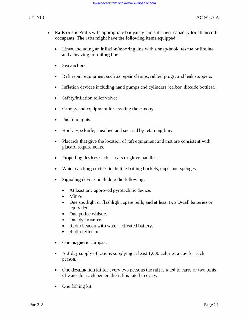
j. Survival Equipment. Operators are responsible for ensuring they comply with 14 CFR and any foreign airspace requirements concerning use of survival equipment. This equipment list is not complete but includes the following items:
• Life preserver for each occupant.
Page 20 Par 3-2
Downloaded from http://www.everyspec.com
8/12/10 AC 91-70A
• Rafts or slide/rafts with appropriate buoyancy and sufficient capacity for all aircraft occupants. The rafts might have the following items equipped:
• Lines, including an inflation/mooring line with a snap-hook, rescue or lifeline, and a heaving or trailing line.
• Sea anchors.
• Raft repair equipment such as repair clamps, rubber plugs, and leak stoppers.
• Inflation devices including hand pumps and cylinders (carbon dioxide bottles).
• Safety/inflation relief valves.
• Canopy and equipment for erecting the canopy.
• Position lights.
• Hook-type knife, sheathed and secured by retaining line.
• Placards that give the location of raft equipment and that are consistent with placard requirements.
• Propelling devices such as oars or glove paddles.
• Water catching devices including bailing buckets, cups, and sponges.
• Signaling devices including the following:
• At least one approved pyrotechnic device. • Mirror. • One spotlight or flashlight, spare bulb, and at least two D-cell batteries or
equivalent. • One police whistle. • One dye marker. • Radio beacon with water-activated battery. • Radio reflector.
• One magnetic compass.
• A 2-day supply of rations supplying at least 1,000 calories a day for each person.
• One desalination kit for every two persons the raft is rated to carry or two pints of water for each person the raft is rated to carry.
• One fishing kit.
Par 3-2 Page 21
Downloaded from http://www.everyspec.com

AC 91-70A 8/12/10
Page 22 Par 3-2
• One book on survival appropriate for any area.
• A survival kit, appropriately equipped. The kit could include some of the following items:
• Triangular cloths. • Bandages. • Eye ointments. • Water disinfection tablets. • Sun protection balsam. • Heat retention foils. • Burning glass. • Seasickness tablets. • Ammonia inhalants.
3-3. ATC. Oceanic and remote airspace is mostly non-radar (i.e., where the separation of aircraft does not depend on ground-based radar coverage) and considered procedural airspace. Therefore, it is paramount crews operate with strict discipline and adherence to ATC clearances and all procedures, both normal and contingency. You may find detailed ICAO procedures for specific geographical areas in ICAO Regional Document 7030, Regional Supplementary Procedures, and in this AC. FAA ATC generally base their procedures for oceanic and remote airspace on ICAO standards.
NOTE: ATC monitors the compliance with the issued clearance for all aircraft entering and/or departing international airspace under U.S. jurisdiction. Navigation performance is monitored by the United States for all aircraft entering and/or departing international airspace under U.S. jurisdiction. All deviations of 20 NM or more are reported and investigated.
a. U.S. Oceanic Service Areas. The United States provides ATS in oceanic airspace as follows:
• Atlantic Ocean: New York, Miami, and San Juan FIRs. • Gulf of Mexico: Miami and Houston FIRs. • Pacific Ocean: Oakland and Anchorage FIRs.
b. Flight Planning. A flight plan is required for all flights that cross international borders. IFR operations in oceanic airspace generally start at 6,000 feet. VFR operations below 6,000 feet must comply with all applicable regulations and foreign airspace requirements. The FAA only permits operations in offshore airspace (the airspace between the U.S. 12-mile limit and the oceanic control area (OCA)/FIR boundary) on a VFR flight plan between sunrise and sunset and at or below flight level (FL) 200. Even though you may legally conduct flights using VFRs, experience indicates that you will encounter instrument meteorological conditions (IMC) at some
Downloaded from http://www.everyspec.com

8/12/10 AC 91-70A
point in a transoceanic flight. Consequently, we recommend that the pilot is instrument rated, that the aircraft meet the equipment requirements for IFR flight, and file an IFR flight plan.
c. Navigation/Communication Equipment. In most cases, aircraft operating over the high seas will not have adequate very high frequency (VHF) radio and/or ICAO standard Navigational Aid (NAVAID) VHF Omnidirectional Range (VOR), VOR/distance measuring equipment (DME), and non-directional radio beacon (NDB)) coverage. High frequency (HF) communication capabilities, provided by Aeronautical Radio, Inc. (ARINC), are available throughout most of U.S.-controlled oceanic airspace. In some U.S.-controlled oceanic airspace, you can use Global Navigation Satellite System (GNSS) and data link. Notwithstanding the fact that pilots must comply with all regulations applicable to their flight, all aircraft operating over the high seas must equip suitable instruments and navigation equipment appropriate to the route to be flown (§ 91.703, ICAO Annex 2, section 5.1.1, and this chapter). The aircraft must also equip a functioning two-way radio to maintain a continuous listening watch on the appropriate radio frequency and establish two-way radio communications with the appropriate ATC unit (ICAO Annex 2, section 3.6.5.1). It is not acceptable to depend on radio relay operations to satisfy this requirement.
NOTE: Oceanic and remote airspace communication and navigation requirements are rapidly evolving. The operator must ensure it has the appropriate approvals based on the airspace requirements.
d. Position Reporting. Make position reports to the ATS provider for the airspace where you operate the aircraft. In addition, when so prescribed by the appropriate AIP or requested by ATC, make the last position report before passing from one FIR or CTA to an adjacent FIR or CTA to the ATS you are about to enter. Make position reports when over the fix, or as soon as passing, each designated compulsory reporting point. When required for ATS purposes, the appropriate ATS may request additional reports over other points.
(1) Appropriate Time Intervals for Position Reports. On routes not defined by designated significant points, make reports as soon as possible after the first half hour of flight and at hourly intervals thereafter. The maximum interval is 1 hour and 20 minutes. The appropriate ATC unit, when required for ATS purposes, may request additional reports at shorter intervals of time. In cases where adequate flight progress data is available from other sources such as ground radar, and in other situations where the omission of routine reports from selected flights is acceptable, flights may be exempt from the requirement to make position reports at each designated compulsory reporting point or interval. However, you should take account of the requirement for making, recording, and reporting of routine aircraft observations (see “Reporting of Operational and Meteorological Information” below).
(2) Oceanic Position Procedures. Oceanic position procedures call for aircraft reporting of all designated reporting points when following a designated oceanic route. If operating in airspace approved for the use of data link or in a separation standard that requires the use of data link, you may accomplish position reporting with a periodic contract with Automatic Dependent Surveillance-Contract (ADS-C). Otherwise, report positions at designated lines of latitude and longitude. Flights whose tracks are predominantly east and west will report over each 5 or 10° meridian of longitude. Flights whose tracks are predominantly north and
Par 3-3 Page 23
Downloaded from http://www.everyspec.com
AC 91-70A 8/12/10
south will report over each 5° or 10° parallel of latitude. If the speed of the aircraft is such that it will allow it to traverse 10° within 1 hour 20 minutes or less and over each 5° if the aircraft is slower, make reports over each 10° parallel/meridian. Transmit position reports at the time of crossing the designated reporting point or designated reporting line, or as soon thereafter as possible. Flights operating within international airspace should make position reports, either directly or by relay.
NOTE: Transmit relays over the appropriate air-to-air frequency and not over the emergency frequency.
e. Position Report Format.
• Complete aircraft call sign.
• For flights reporting coordinates rather than specified named reporting points, east-west oriented flights report latitude in degrees and minutes, longitude in degrees only. North-south oriented flights should report latitude in degrees only and longitude in degrees and minutes.
• Position time in four digits universal coordinated time (UTC).
• FL.
• Next fix and estimate over next fix in four digits.
• Name of subsequent fix.
NOTE: ATC may require meteorological reports, if requested.
f. ATC Service.
(1) Air route traffic control centers (ARTCC) in oceanic controlled airspace provide ATC separation to all flights. These facilities issue clearances and instructions providing separation vertically and horizontally (laterally and longitudinally). The horizontal distances between separated aircraft generally exceed those applied over land. Controllers may apply reduced longitudinal separation in oceanic airspace between turbojet aircraft cleared to maintain a specific Mach speed. In some cases, controllers can apply reduced separation without the application of Mach number technique.
NOTE: You can find specific information regarding ATC separation standards in the current edition of FAA Order 7110.65, Air Traffic Control.
(2) You may find the most current information on oceanic separation standards and operational authorizations on the following FAA and international Web sites:
• www.faa.gov/about/office_org/headquarters_offices/ato/service_units/enroute/ rvsm/.
Page 24 Par 3-3
Downloaded from http://www.everyspec.com

8/12/10 AC 91-70A
• www.faa.gov/air_traffic/publications/ifim/.
• http://www.paris.icao.int.
g. Warning Areas. International airspace has established warning areas to contain operations hazardous to non-participating aircraft. The FAA and the military may jointly use some of these areas. The FAA will issue instrument flight rules (IFR) clearances through these areas whenever hazardous operations are not taking place. Carefully review charts for those areas while flight planning, taking note of the area operating times and restrictions.
NOTE: Operators are also responsible for knowing the requirements for prohibited and restricted airspace in oceanic operations.
h. Altimeter Settings. Operations in international airspace demand that pilots are aware of, and understand the use of, the three types of altimeter settings.
NOTE: Most overseas airports give altimeter settings in hectopascals (hPa) (millibars). Therefore, it is imperative that pilots are able to convert inches of mercury to hPa or hPa to inches of mercury.
(1) Altitude Above Ground (QFE). A local altimeter setting equivalent to the barometric pressure measured at an airport altimeter datum, usually signifying the approach end of the runway is in use. At the airport altimeter datum, an altimeter set to QFE indicates zero altitude. If required to use QFE altimetry, altimeters are set to QFE while operating at or below the transition altitude and below the transition level. On the airport, the altimeter will read “0” feet.
(2) Barometric Pressure for Standard Altimeter Setting (QNE). Use the altimeter setting (en route) at or above the transition altitude (FL 180 in the United States). The altimeter setting is always 29.92 inches of mercury/1013.2 hPa for a QNE altitude.
NOTE: Transition levels differ from country to country and pilots should be particularly alert when making a climb or descent in a foreign area.
(3) Barometric Pressure for Local Altimeter Setting (QNH). A local altimeter setting equivalent to the barometric pressure measured at an airport altimeter datum and corrected to sea level pressure. At the airport altimeter datum, an altimeter set to QNH indicates airport elevation above mean sea level (MSL). Altimeters are set to QNH while operating at and below the transition altitude and below the transition level.
(a) For flights in the vicinity of airports, express the vertical position of aircraft in terms of QNH or QFE at or below the transition altitude and in terms of QNE at or above the transition level. While passing through the transition layer, express vertical position in terms of FLs when ascending and in terms of altitudes when descending.
(b) When an aircraft that receives a clearance as number one to land completes its approach using QFE, express the vertical position of the aircraft in terms of height above the airport elevation during that portion of its flight for which you may use QFE.
Par 3-3 Page 25
Downloaded from http://www.everyspec.com

AC 91-70A 8/12/10
Page 26 Par 3-3
i. Reporting of Operational and Meteorological Information. When an aircraft en route reports operational and/or routine meteorological information at points or times that require position reports, give the position report in a format that ATC requires.
j. National Security. Title 14 CFR part 99 governs national security in the control of air traffic. Following the events of September 11, 2001, the threat of terrorism has brought about numerous changes to security protection procedures in the United States. The FAA expects many additional changes in the United States and internationally will take place and operators should check the latest AIP and all NOTAMs to ensure compliance with security requirements. Additionally, operators intending to operate in or cross any United States air defense identification zone (ADIZ) should make a detailed review of part 99 and the IFIM.
k. International Interception Procedures. There are occasions that require pilots to transmit instructions to pilots of intercepted aircraft. ICAO Annex 2, chapter 3, paragraph 3.8, and attachment A contains guidance for international interception procedures. Appendix 1 of Annex 2 contains international interception signals.
3-4. OCEANIC COMMUNICATIONS. Radio frequencies are constantly changing. Thus, it is important that operators consult current oceanic charts and the FAA Website at www.faa.gov/air_traffic/publications/ifim/ for the most up-to-date information.
a. Data Link Communications. We base data link requirements on ICAO standards (for additional guidance, see AC 120-70A, Operational Authorization Process for Use of Data Link Communication System, current edition). Operators should consult geographic-specific areas of this document. Operators can also consult the Future Air Navigation System (FANS) Operation Manual for data link procedures and operations.
b. Satellite Communications (SATCOM) Voice. The current requirements for remote oceanic operations are two HF radios. At this time, non-routine and emergency purposes only allow SATCOM Voice. As this technology evolves, operators must ensure that they comply with the latest authorizations.
c. In-flight Broadcast Procedures. Some remote geographic regions of the world, which provide only limited communication and ATS, require the pilots’ understanding and regular use of in-flight broadcast procedures.
(1) Navigation Charts. Commercially-published navigation charts contain details of communication procedures on inserted panels. In addition, the North Atlantic Systems Planning Group (NAT SPG) publishes the North Atlantic MNPS Airspace Operation Manual, which is available on the following Web site: www.paris.icao.int/. This North Atlantic MNPS Airspace Operations Manual details all aspects of North Atlantic Operations (NAT/OPS) and includes communication and navigation procedures. The guidance and information material contained here concerns flight operations in the NAT region. It deals primarily with approval for operations in the NAT region and with the planning and management of such operations. It addresses mainly state aviation authorities/administrations and ATS Provider States and Operators.
(2) Operation Manuals. Some of the material in this document is of interest to pilots; however, more detailed information for pilots is in the North Atlantic MNPS Airspace
Downloaded from http://www.everyspec.com

8/12/10 AC 91-70A
Operations Manual (issued by the European and North Atlantic (EUR/NAT) Offices of ICAO) and in the North Atlantic International General Aviation Operations Manual (issued by the FAA). NAT SPG, on its behalf, produce these two manuals. Although primarily intended for use by pilots, it is important that the operators use the manuals to ensure that flightcrews, for whom they are responsible for, have adequate training and equipment for NAT/OPS.
NOTE: You can download the North Atlantic International General Aviation Operations Manual from the FAA Web site at www.faa.gov/atpubs.
d. Summary of Communication and Reporting Procedures. Maintain continuous contact with the controlling agency. This can be through VHF, HF, data link, SATCOM Voice or Selective Call (SELCAL). The range of VHF is approximately 200 NM; communication beyond that distance requires HF or SATCOM data link. A family of frequencies is normally assigned based on route and/or the state where the aircraft is registered. En route charts list these families of frequencies.
e. Emergency Frequencies.
• VHF: 121.5. • Ultrahigh frequency (UHF): 243.0. • HF: 2182/4125.
3-5. NAVIGATION PROCEDURES (NAVIGATION SENSORS—INERTIAL NAVIGATION SYSTEM (INS), INERTIAL REFERENCE SYSTEMS (IRS), OR GNSS).
a. Journey Logbooks. ICAO Annex 2 requires the use of a journey logbook, also known as the “master” document. This “master” document is typically a computer flight plan (CFP). Operator procedures must include a designated “master” document for use on the flight deck. This document must include information that sequentially lists the waypoints that define the routes, distances between the waypoints, and any other navigation information pertinent to the cleared route. Misuse of the master document can result in serious navigational errors.
b. Application of Master Document. Strict procedures should be used in the management of this document. These procedures should include the following:
NOTE: These procedures are general; operators should consult specific guidance based on the type of long range navigation system (LRNS) configuration.
• Use only one copy of the master document in the cockpit.
• Use a waypoint/numbering sequence procedure from the outset of the flight. Enter this sequence on the master document and also use it to store waypoints in the navigational computer. Adopt the appropriate symbology to indicate the status of each waypoint listed on the master document. For example:
• Verify the waypoints by comparing the master document and the LRNS;
Par 3-4 Page 27
Downloaded from http://www.everyspec.com

AC 91-70A 8/12/10
• Circle the waypoint, waypoint number, or symbol to signify that another crewmember independently cross-checks the entry of the coordinates in the navigation computer;
• Tick or diagonally slash the circled waypoint, waypoint number, or symbol to signify the cross-checking of track and distance information within a specified tolerance; and
NOTE: Some operators use a diagonal line approaching a waypoint to confirm a subsequent waypoint to include coordinates, track, and distance.
• Cross out the circled waypoint, waypoint number, or symbol to signify that the aircraft has passed the waypoint. Pilots must verify all navigational information contained in the master document against the best available primary data source. Cross out old waypoints and insert the new information.
• If they receive an ATS route change or the ATC clearance changes, pilots must update the master document to reflect the change.
• While obtaining ATC clearances, it is recommended to wear headsets because loudspeaker distortion is known to result in errors. Two qualified crewmembers must monitor and independently verify all clearances received. The crew should read all waypoint coordinates back in detail unless approved local procedures make this unnecessary. In that case, cross-check each detail with the master document.
3-6. POSITION PLOTTING.
a. Plotting and Systematic Cross-Checking of Navigation Information. During all phases of flight in Class II navigation, each operator’s long-range navigation program (LRNP) will require the standardized application of disciplined, systematic cross-checking of navigation information.
(1) Plotting Procedures Impact. Plotting procedures have had a significant impact on the reduction of gross navigation errors (GNE). There is a requirement to plot the route of flight on a plotting chart and to plot the computer position approximately 10 minutes after waypoint passage. This may or may not require plotting, depending upon the distance between the standard ICAO ground-based NAVAIDs. This applies to all operators.
(2) Turbojet Operations. All turbojet operations, where the route segment between the operational service volume of ICAO standard ground-based NAVAIDs exceeds 725 NM, require plotting procedures.
(3) Turboprop Operations. All turboprop operations, where the route segment between the operational service volume of ICAO standard ground-based NAVAIDs exceeds 450 NM, require plotting procedures.
Page 28 Par 3-5
Downloaded from http://www.everyspec.com

8/12/10 AC 91-70A
(4) Plotting Procedures for Special Conditions. The Administrator requires plotting procedures for routes of shorter duration that transit airspace where special conditions exist, such as reduced lateral and vertical separation standards, high density traffic, proximity, or potentially hostile border areas.
(5) Reviewing and Revising Approvals. Review and revise any existing approvals that differ from the plotting requirements in this chapter and Class II navigation procedures as necessary. Direction and guidance is available from the navigation specialists in coordination with AFS-400.
(6) Plotting Charts. The FAA requires crews to use a plotting chart to provide themselves with a visual presentation of the intended route. Regardless of the type of LRNS in use, operators must use plotting charts. Plotting the route will increase SA and reveal errors or discrepancies in the navigational coordinates that flightcrews can correct before such errors can cause a deviation from the ATC cleared route. As the flight progresses, plotting the position approximately 10 minutes after passing each waypoint helps confirm that the flight is on course. If the plotted position indicates off track, the flight may have deviated unintentionally and the flightcrew should investigate at once.
(7) Plotting Chart Requirements. The plotting chart must include, at a minimum:
• The route of the currently effective ATC clearance;
• Clearly depicted waypoints using standardized symbology; and
• Ten-minute plotted positions after passing each oceanic waypoint, including coordinates, time, and graphic depictions of all ETPs.
NOTE: Operators’ SA should include such items as alternate airports and proximity of other tracks.
b. Human Factors Issues for Confirmation of Currently Effective ATC Clearance. When cross-checking the LRNS entries or the plotting chart entries, pilots should read from “entered” data back to the master document.
c. Relief Crewmembers. Flightcrews conducting long-range operations may include a relief pilot. In such cases, crews must ensure the continuity of the operation and brief the relief pilot on all current operational issues affecting the flight.
d. INS/IRS/Inertial Reference Units (IRU) System Alignment. Complete INS alignment and switch the equipment to “nav” mode prior to releasing the parking brake at the ramp. There are various ways of ensuring that there is adequate time for this operation.
(1) Align Mode. Have the first crewmember on the flight deck place the system in “align” mode as early as possible. At short transit stops, leave the equipment in “nav” mode provided that the system errors are not so large as to require INS realignment. The decision to realign may depend on the size of the error as well as the length and nature of the next leg. You cannot recharge INS batteries, which usually have a limited-life, onboard if allowed to run down.
Par 3-6 Page 29
Downloaded from http://www.everyspec.com

AC 91-70A 8/12/10
(2) Monitor Ground Power Interruption. If the INS is left in “nav” mode during a transit stop, or if you switch the INS on for alignment, it is imperative that an individual is responsible for monitoring ground power interruption.
(3) Overheat Protection. Some INS systems provide overheat protection in “standby” and “align,” but not in other modes.
(4) Align at Tropical Terminals. During stops at tropical terminals, put the mode selector directly to “align” (not through “standby,” which would cause realignment).
e. Initial Insertion of Latitude and Longitude. Early in the course of the preflight check, load the aircraft’s position into the INS and verify. Check this position against an authoritative reference source before insertion. Any latitude error in the initial position will introduce a systematic error that you cannot remove during flight by updating, resulting in erroneous position indications. Check for a correct insertion of present position before the “align” mode is selected and the position is recorded in the master document. Subsequently, both pilots independently make silent position checks during an early stage of the preflight check. In the case of some INS, insertion errors exceeding 1º of latitude will activate a malfunction light. However, very few systems provide similar protection against erroneous longitudinal insertion errors. At all times, take care to ensure that previously inserted coordinates are correct.
f. Verification of Present Position/Initial Position. Regardless of the type of LRNS or the method of insertion, crews will verify current ramp position in the LRNS against current aeronautical publications.
g. INS Loading of Initial Waypoints. Two people working in sequence and independently must conduct the entry of waypoint data into the navigation system as a coordinated operation. One should key in the data and the other person should recall and confirm the data against source information. It is not sufficient for one crewmember to simply observe another crewmember entering the data. The pilots should use waypoint 1 for the ramp position of the aircraft. The pilots should load at least two additional waypoints while the aircraft is on the ramp or they may load all waypoints at this time. However, it is more important to ensure that the second waypoint is inserted accurately than to attempt to load all waypoint data. The second waypoint should associate with the first significant position along the route (approximately 100 NM from departure point). Positions associated with ATC standard instrument departures (SID) should not normally be used for this purpose. During flight, the control display unit (CDU) should maintain at least two current waypoints beyond the navigated sector until the pilots load the destination ramp coordinates. The pilots should be responsible for loading, recalling, and checking the accuracy of the loaded waypoints. Each pilot should cross-check the other’s work. In no case should this process engage the attention of both pilots simultaneously during flight. An acceptable procedure is for the pilots to independently load their own waypoints and then cross-check them. The pilot responsible for verification should work from the CDU display to the master document, lessening the risk of seeing what is expected rather than the actual information. After the pilots load the initial waypoints, they should select the route between waypoints 1 and 2 and the auto track change.
Page 30 Par 3-6
Downloaded from http://www.everyspec.com

8/12/10 AC 91-70A
h. INS Flight Plan Check. The purpose of the flight plan check is to ensure complete compatibility between the master document and the programming of the navigation system. To verify the correct distance from the ramp position to waypoint 2, select “dis/time.” You may have to consider an appropriate allowance since the great circle distance shown on the CDUs may be less than the flight plan as a consequence of the additional mileage involved in ATC SIDs. However, a significant disparity requires a recheck of “pos” and waypoint 2 coordinates:
• Select “remote” and track change 1-2. Check the accuracy of the indicated distance against that listed in the master document.
• Select “dstrk” and check that the desired track indicated on the CDU is the same as that in the master document. This track check will reveal any errors in the latitude and longitude designators.
• Perform similar track and distance checks for subsequent pairs of waypoints and any discrepancies between the CDU information and the master document. Coordinate these checks against the master document between themselves.
• After checking each leg of the flight as described above, make a note on the master document using the appropriate symbols.
i. INS Procedures Leaving the Ramp. If the aircraft moves before initiating the “nav” mode, realign the INS. Relocate the aircraft so that it does not block the gate or otherwise interfere with traffic while the realignment takes place. After leaving the ramp, check INS groundspeeds. Perform a check of the malfunction codes while the aircraft stops but after it has taxied at least part of the way to the takeoff position. Any significant groundspeed indication while stationary may indicate a faulty unit.
j. In-flight. If you conduct the initial part of the flight along airways, the flightcrews should use the airways facilities as the primary NAVAIDs and monitor the aircraft navigation system to ascertain which system is giving the most accurate performance.
k. Approaching the Ocean. The FAA requires crews to verify the accuracy of the LRNS before entering Class II airspace. Crews must complete the accuracy verification (without updates) using ground-based NAVAIDs. The crew will conduct the gross error check of the LRNS in Class I airspace. The crew may use an ATC radar plot to verify the gross error check. The crew will record the coordinates and the time of the gross error check.
(1) Aircraft Position Check with NAVAIDs. Before entering oceanic airspace, check the aircraft’s position as accurately as possible by using external NAVAIDs to ascertain which aircraft navigation system to use. This may require DME and/or VOR/DME checks to determine navigation system errors through displayed and actual positions.
(2) Updating Navigation the System. In the event of significant discrepancies (greater than 2 NM), consider updating the navigation system. We do not normally recommend updating when the discrepancy is less than 6 NM.
Par 3-6 Page 31
Downloaded from http://www.everyspec.com
AC 91-70A 8/12/10
(3) Influential Factors in System Updating. The duration of the flight before the oceanic boundary and the accuracy of the external navigation system are factors that influence any decision to update the system. If the system received an update, follow the proper procedures with the aid of a prepared checklist.
(4) Auto-Coupling. Select the navigation system that performs the most accurately for auto-coupling. In view of the importance of following the correct track in oceanic airspace, some operators advise that the third pilot or equivalent crewmember should check the inserted waypoints using appropriate source information.
l. Oceanic Entry. Crews must ensure they have given an accurate estimated time of arrival (ETA) to ATC for their oceanic entry point. They must also ensure they entered the ocean at the cleared FL.
m. Oceanic Boundary Position Report. Just prior to the oceanic boundary and prior to any waypoint, the crew should monitor, record, and verify the present position coordinates. Check and verify the coordinates for the next waypoint. When the CDU alert light comes on, the crew should note and record the present position on the master document. Verify this information against the current clearance on the master document. Annotate the waypoint number on the master document with the appropriate symbol to indicate its verification. If you make the oceanic boundary position report over a VOR facility, select the appropriate radial to the first oceanic waypoint as a further check shows that the navigation system is tracking according to the current clearance. If DME is available, you can also perform a distance check.
n. Approaching an Oceanic Waypoint. Two minutes before reaching each oceanic waypoint, crews should verify the accuracy of the subsequent waypoint. This verification should include the expected outbound course and distance of the currently effective ATC clearance.
o. At Each Oceanic Waypoint. Crews must ensure that when overhead each oceanic waypoint, the aircraft turns to the anticipated heading and that the distance to the next waypoint is accurate. Verify the coordinates of the next waypoint against the master document. After the ATC position report is sent, plot the present position to ensure that the tracking is correct. The crew should be particularly alert in maintaining SELCAL watch in the event of possible ATC followup to the position watch.
NOTE: Crews must not assume the aircraft has automatically transitioned to the next waypoint.
p. Ten-Minute Position Plotting. Approximately 10 minutes after transitioning each oceanic waypoint, crews will plot their LRNS position and note the coordinates and time on the plotting chart. When sending the ATC position report, copy the coordinates from the master document or the present position and you can read the next two forward positions from the CDU. As soon as the waypoint alert light goes on, check the present position coordinates of each navigation system against the current clearance to ensure that the position report coincides with the actual position of the aircraft and the ATC clearance.
q. Routine Monitoring. Operators must ensure they have procedures in their International Operations Manual concerning which page(s) the PIC will routinely monitor versus the pages the
Page 32 Par 3-6
Downloaded from http://www.everyspec.com

8/12/10 AC 91-70A
SIC routinely monitors. For example, the PIC may monitor the cross-track error (XTK) page and the second in command (SIC) may monitor distance/time.
(1) Position Coordinates. There are a number of ways in which you may accidentally disconnect the autopilot (AP) from the command mode. Crews should make regular checks of correct engagement. Although it is a common practice to display “dist/track,” the FAA recommends that the navigation system coupled to the AP display the present position coordinates throughout the flight. If plotting the coordinates at roughly 20-minute intervals, they will confirm that the flight is on track according to the ATC clearance. Distance-to-go information should be available on the instrument panel, and the waypoint alert light provides a reminder of the proximity of the waypoint.
(2) XTK and Track Angle Error (TKE). If a crew makes a position check and verification at each waypoint and 10 minutes after each waypoint, additional plotting every 20 minutes may be counterproductive during routine flight. The navigation equipment not used to steer the aircraft should display XTK and TKE. Monitor these indicators with XTK displayed on the horizontal situation indicator (HSI) when feasible.
r. Use of Radar. Aircraft equipped with airborne weather radar capable of ground mapping should use the radar to observe any land masses as an aid to determining the accuracy of their navigation. The flightcrews must use the radar on a constant basis during flight to monitor navigation system accuracy.
s. Approaching Landfall. When the aircraft is approaching the first landfall NAVAID, it should acquire the appropriate inbound radial as soon as the flightcrew is confident that the NAVAID information is accurate.
t. Navigation System Accuracy Check. At the end of each flight, determine the accuracy of the navigational system to facilitate correction of performance. You may perform a check to determine the radial error at the ramp position as soon as the aircraft parks. Radial errors for INSs in excess of 2 NM per hour are generally considered excessive (part 121, appendix G). Keep records on each individual navigation system performance.
u. Monitoring During Distractions. Training and drills ensure that minor emergencies or interruptions of normal routine do not distract the crew to the extent of mishandling the navigation system. If the AP disconnects during flight, re-engage it carefully to ensure that you follow the correct procedure.
v. Avoiding Confusion Between Magnetic and True. To cover all navigation requirements, some air carriers produce flight plans that include both magnetic and true tracks. If crews are changing to a new system, there is a risk of confusion in selecting the correct values. Operators should devise drills to reduce this risk and ensure that training covers this subject. Crews that check or update their LRNS by reference to VORs located in the Canadian Northern Control Area (NCA) should remember to not align them with reference to magnetic north.
w. Navigation in Areas of Magnetic Unreliability (AMU). The FAA designates Canada’s NCA and Arctic Control Area (ACA) as AMUs. Although Canadian publications sometimes refer to it as the area of compass unreliability, they are the same. The magnetic North
Par 3-6 Page 33
Downloaded from http://www.everyspec.com

AC 91-70A 8/12/10
Pole is at approximately 75°N 100°W and is slowly moving as it circles the true pole every 960 years. This is why we see current navigation charts occasionally changing an instrument landing system (ILS) course by 1º.
(1) Magnetic North Pole. When you approach the magnetic North Pole, horizontal magnetic influences decrease and vertical magnetic influences increase to a point where the compass is no longer reliable (the magnetic pole is below the aircraft). It is common to see the compass drifting aimlessly or tilting in its case due to the vertical component even when hundreds of miles from the magnetic North Pole. The better the magnetic compass, the closer to the magnetic pole it will operate. Within about 250 miles of the magnetic pole, all aircraft magnetic compasses will be useless. As a result, some VORs, runways, and radar vectors in Canada’s NCA and ACA are oriented to true north.
(2) AMU. When operating in the AMU, move the HDG REF switch to TRUE when the Canada HI 4 chart defines the course with a °T. Add two additional items to the master flight plan checklist: TRUE HDG adjacent to the first true heading leg and MAG HDG at the end of the AMU. This will serve as a reminder to return to a normal heading reference. The primary reason for selecting TRUE HDG in the NCA and ACA is to provide a more realistic navigation display (ND) heading presentation, thus avoiding rapidly changing heading indications. This will help with radar vectors in TRUE and comply with Canadian Air Regulations.
x. Navigation in Areas of Convergence. Because of the rapid changes in variation and due to meridian convergence, you may note a considerable difference between the flight plan course and the flight management computer (FMC) course when conducting the Class II navigation checks. The flight plan entry consists of the average for the leg while the FMC displays the course at the start of the leg. If a significant difference exists between the two, then you can confirm the course by checking it in TRUE, which will eliminate the large changes in variation. In the far north, convergence is so great that even in TRUE there may be a considerable difference between the flight plan and the FMC. If this is the case, check the FMC against the Canada HI 4 chart. The course at the start of the leg on the chart should agree with the FMC. If averaging the outbound and inbound courses of the leg on the Canada HI 4, the result should closely agree with the flight plan.
NOTE: The direct route from Thule to Cambridge Bay in a southwesterly direction begins on a course of 254°T and ends on 219°T. This is a 35° change because of convergence. The variation at Thule is 66°W and the variation at Cambridge Bay is 25°E. This results in a magnetic course of 320°M departing Thule and a 194°M course arriving over Cambridge Bay. This change of 126°M is due to the effects of convergence and variation while flying a great circle route. It is evident that even though the flight in this example is south of 82°N, select a true heading reference, thus allowing a more realistic heading presentation. If this were flown as a single leg, it would be necessary to do the Class II course check using the Canada HI 4 chart as described above in order to get a valid check. The FMC in TRUE should closely agree with the charted outbound course of 254°T and the flight plan should closely agree with the average of 254°T outbound and 219°T inbound, which is 236°T.
Page 34 Par 3-6
Downloaded from http://www.everyspec.com

8/12/10 AC 91-70A
y. Weather Deviations. Temporary diversions from track are sometimes necessary, but obtain prior ATC clearance. Such diversions can cause GNEs if you do not re-engage the navigation mode of the AP. Selection of the AP turbulence mode (if applicable) can disengage the AP from the navigation system. After using turbulence mode, fly the aircraft back to the desired track before re-engaging the AP. For inertial platform aircraft, the following steps are useful in preventing GNEs as a result of diversions around severe weather:
• Use the AP turn control knob to turn the aircraft in the desired direction.
• The AP engage switch will automatically move from “command” to “manual.”
• The altitude mode switch will either remain on “altitude hold,” or if in the “altitude select” mode, will trip to “off.”
• Set the steering CDU selector to XTK/TKE to provide a continuous display of cross-track data.
• If encountering turbulence, you may use the “turb” setting on the speed mode selector. In this case, the altitude mode switch automatically positions to “off.”
• Both radio INS switches remain in the INS position. This provides a visual display of the navigation situation on the HSI. Even if more than 8 NM off the track, the pegged needle on the HSI is a reminder of that fact and confirms whether the aircraft is tracking towards, away from, or parallel to the desired track.
• Use the turn control knob to maneuver the aircraft as necessary.
• When clear of the severe weather, steer the aircraft back to the desired track, guided by the steering CDU to zero the XTK indication.
• When the aircraft returns to the desired track, set the AP engage switch to “command” and the altitude mode switch to “altitude hold.” The navigation mode selector should still be in the INS position.
• The captain and first officer, or the entire crew if possible, should monitor the diversion maneuver to ensure that the aircraft has returned to the desired track and if you properly re-engaged the AP for command INS operation.
• After completing return to route, check the assigned Mach number and advise ATC.
z. ATC Re-Clearance. Scrutiny groups determined that a re-clearance scenario is the greatest contributor to an oceanic error (e.g., GNE, Large Height Deviation (LHD)). Experience suggests that when ATC issues a clearance involving rerouting and new waypoints, the risk of error increases. The procedures used to copy the ATC clearance, load and check the waypoints, verify the flight plan information, and prepare a new plotting chart should be the same as the procedures for beginning a flight. Designate one pilot to fly the aircraft while the other pilot reprograms the navigation systems and amends the cockpit documents. In the event that a
Par 3-6 Page 35
Downloaded from http://www.everyspec.com

AC 91-70A 8/12/10
re-clearance involves a direct routing, retain the data relevant to the original route in case ATC requires the aircraft to return to its original course.
aa. Detecting Failures. Inertial and global positioning system (GPS) installations typically include comparator and/or warning devices, but the crew must still make frequent comparison checks. With three systems onboard, identification of a defective system should be straightforward. Identifying system failures with two systems is more difficult. If a significant deviation occurs in oceanic airspace, contact nearby aircraft on 123.45 MHz and obtain information to aid in identifying a system failure. Maintain and keep a record of GPS or inertial performance available for crews. The following are suggestions for recordkeeping:
• Before takeoff and while stationary, note the inertial groundspeed and position indicators. These may give an indication of system accuracy.
• Note the accuracy of each unit before reaching oceanic airspace, preferably while passing a convenient short-range facility. Make a further record at the destination regarding terminal error after first canceling any in-flight updates made.
• You can make compass deviation checks (inertial only) to determine deviation values for the magnetic compass systems so that you can check the accuracy of the inertial heading outputs in-flight.
bb. Identifying Faulty Systems.
• Check malfunction codes for indications unserviceability.
• Refer to records for indications of prior problems.
• Obtain a fix, possibly using the weather radar, in order to determine position relative to information from other systems.
• Communicate with nearby aircraft on air-to-air VHF to compare information on spot wind, groundspeed, and drift. Compare information from the prognostic chart to the system readout if there is no contact with any aircraft. Use this method as a last resort and preferably should use it with another method of verification.
• Use the heading method (inertial only). Simultaneously read both the inertial and magnetic compass indicators. Obtain the mean to the nearest degree to get an acceptably accurate true heading value to compare to the inertial readings and determine what reading is inaccurate.
• Situations may arise when distance or cross-track differences develop between two LRNSs, but the crew cannot identify the faulty system. If three systems are onboard, accept the two agreeing systems as reliable signals. If, however, only two systems are onboard and they disagree, most operators believe that the best procedure in this instance is to fly the aircraft halfway between the cross-track
Page 36 Par 3-6
Downloaded from http://www.everyspec.com

8/12/10 AC 91-70A
differences as long as uncertainty exists. Inform ATC that the flight is experiencing navigation difficulties so that you may obtain the appropriate clearance.
• Compare the number of satellites received (GPS or GPS-augmented systems) by each receiver.
cc. Attributes of a Failed System. Crews must be able to determine when an inertial or GPS system fails. Crews must notify ATC. The red warning light, self-diagnostic indications, or an error over a known position exceeding the value agreed upon by the operator and the certifying authority may indicate inertial failure. Generally, if there is a difference of greater than 15 NM between the two aircrafts’ navigation systems, it is advisable to split the difference to determine the aircraft’s position. If the disparity exceeds 25 NM, assume one or more of the systems have failed.
dd. Loss of Navigation Capability. There are various navigational requirements for oceanic operations. One example refers to the navigation performance (or accuracy) that you should achieve; a second example is the need to carry standby equipment with comparable performance characteristics. Some aircraft carry three or more LRNSs so that if one system fails they still meet the requirements. The following guidance is for aircraft with two systems:
• If one system fails before takeoff, the pilot must delay departure until repairs are made.
• If a system fails before the aircraft reaches an oceanic boundary, the pilot must land at a suitable airport before the boundary, return to the departure airport or request an ATC clearance on a route that does not require dual LRNS.
• If a system fails after the aircraft crosses the oceanic boundary, the pilot should continue the flight according to the ATC clearance already obtained while keeping in mind that the reliability of the navigational information is significantly reduced. The pilot should assess the reliability of the remaining system and contact ATC with a proposed course of action. Before making any deviation to the existing clearance, obtain ATC clearance.
• While continuing flight in oceanic airspace with a failed system, the pilot should monitor the following:
• The operation of the remaining system(s); • Check the main and standby compass reading against available information; and • Check the performance record for the remaining system.
• If there is doubt about the reliability of the remaining system, the pilot should attempt visual sighting of other aircraft contrails for a track indication, call the appropriate ATC facility to get information on the location of adjacent aircraft, and establish air-to-air communication with nearby aircraft on 123.45 MHz.
Par 3-6 Page 37
Downloaded from http://www.everyspec.com

AC 91-70A 8/12/10
Page 38 Par 3-6
• If the remaining system fails or indicates degradation of performance, the pilot must notify ATC, obtain all possible information from other aircraft, keep visual watch and monitor TCAS for other aircraft, use all possible outside lights, and use any necessary, applicable contingency procedures.
3-7. OCEANIC OPERATIONS.
a. Overview. The chapters in this AC discuss operational factors required for various geographic regions. This AC also discusses various types of navigation equipment. It is the pilot’s responsibility to read the sections that pertain to his/her flights and in addition the general discussion in this chapter. The most stringent conditions exist in the Northern Atlantic due to the high density of traffic between North America and Europe. The most critical area for light aircraft is the long route between the U.S. West Coast and the Hawaiian Islands. Oceanic operating procedures are different depending upon many factors:
• The size of the aircraft. • Type and number of power plants. • Range with or without long-range tanks installed. • Operation type (general or commercial). • Navigation equipment installed. • State (country) of the operator. • Body of water traversed. • Qualifications of the flightcrew. • Airspace-specific requirements.
b. U.S.-Registered Aircraft. Offshore operations in both the Atlantic and Pacific oceans may require FAA authorization issued through OpSpecs, MSpecs or LOAs. The improper application of contingency procedures can result in the loss of separation with other aircraft. It is also a requirement to contact ATC whenever the aircraft is unable to continue flight according to its current ATC clearance. This includes situations when the aircraft is off course and/or unable to maintain its assigned altitude. A failure to comply with this requirement prevents ATC from taking measures to provide separation between adjacent aircraft and the aircraft deviates from its clearance. Failure to contact ATC is also contrary to ICAO Annex 2 and § 91.703, the latter of which requires compliance with Annex 2 by all aircraft of U.S. registry.
3-8. EXTENDED OPERATIONS (ETOPS). Part 121 and 135 operators desiring to obtain approval to operate over a route that contains a point further than 1 hour flying time from an adequate airport should refer to AC 120-42, Extended Range Operations (ETOPS and Polar Operations), current edition. This AC defines the tasks that an operator must accomplish in preparation for the monitoring process that the FAA principal maintenance inspector (PMI) will undertake. This monitoring process is necessary to obtain an ETOPS authorization as stated in the current edition of AC 120-42, which requires an approval from the AFS Director for a
Downloaded from http://www.everyspec.com

8/12/10 AC 91-70A
deviation to the operating rule of § 121.161. To meet the requirements of this deviation, the operator must be able to substantiate that the type design reliability and the performance of the proposed airplane/engine combination have been evaluated per the guidance in AC 120-42. In addition, the operator must be suitable for Extended-Range Operations (ER-OPS) and submit an application package that includes supplemental maintenance requirements and programs that allow for safe operations under an ETOPS authorization.
3-9. STRATEGIC LATERAL OFFSETS IN OCEANIC AIRSPACE TO MITIGATE COLLISION RISK AND WAKE TURBULENCE. Pilots should use the Strategic Lateral Offset Procedure (SLOP) as standard operating practice in the course of normal operations to mitigate collision risk and wake turbulence. The SLOP is in force throughout the New York, Oakland and Anchorage Oceanic FIRs and in oceanic airspace in the San Juan FIR. Internationally, operators implement the SLOP in the NAT, the Pacific (including the NOPAC, Central East Pacific (CEP) and Pacific Organized Track System (PACOTS)) and South Pacific airspaces. Use this procedure for both the heightened risk of collision when non-normal events such as operational altitude deviation errors and turbulence-induced altitude deviations occur due to highly-accurate navigational systems and to mitigate wake vortex encounters.
a. Guidelines. Apply SLOPs using the following guidelines:
• Make strategic lateral offsets and those executed to mitigate the effects of wake turbulence to the right of a route or track only.
• In relation to a route or track, there are three positions that an aircraft may fly: centerline (CL) and 1 or 2 NM right.
• Offsets are not to exceed 2 NM right of CL.
b. Reducing Risk. The intent of this procedure is to reduce risk (increase the safety margin) by distributing aircraft laterally and equally across the three available positions. In this connection, pilots must take into account the following:
• Aircraft without automatic offset programming capability must fly the CL.
• Aircraft programmed with automatic offsets may fly the CL or offset 1 or 2 NM right of CL to obtain lateral spacing from nearby aircraft.
• Pilots should use whatever means are available (e.g., TCAS, communications, visual acquisition, ground proximity warning system (GPWS)) to determine the best flightpath to fly.
• Any aircraft overtaking another aircraft is to offset within the confines of this procedure, if capable, so as to create the least amount of wake turbulence for the overtaken aircraft.
Par 3-8 Page 39
Downloaded from http://www.everyspec.com
AC 91-70A 8/12/10
• For wake turbulence purposes, pilots are also to fly one of the three positions in the second bullet above and never offset to the left of the CL nor offset more than 2 NM right of CL, appropriate to any given situation and have the final authority and responsibility for the safe operation of the aircraft. You may use air-to-air frequency 123.45 to coordinate the best wake turbulence offset option.
NOTE: The FAA recognizes that the pilot will use his/her judgment to determine the action most appropriate to any given situation and has the final authority and responsibility for the safe operation of the aircraft. You may use air-to-air frequency 123.45 to coordinate the best wake turbulence offset option.
• Pilots may apply an offset outbound at the oceanic entry point, but must return to CL at the oceanic exit point.
• Aircraft transiting radar-controlled airspace (e.g., Bermuda) may remain on their established offset positions.
• This procedure does not require ATC clearance and it is not necessary to advise ATC.
• Base voice position reports on the current ATC clearance and not the offset positions.
3-10. OCEANIC EMERGENCY PROCEDURES.
a. Introduction. When conducting flights, especially extended flights outside the United States and its territories, crews should give full consideration to the quality and availability of air navigation services in the airspace used. Operators should obtain as much information as possible concerning the location and range of NAVAIDs and availability of SAR services. Annex 12 to the Convention contains SAR International Standards and Recommended Practices (ISARP). Each ICAO region has published air navigation plans that include the facilities, services, and procedures required for international air navigation within that particular region.
b. Pilot Procedures. Any pilot who experiences an emergency (alert, distress, or uncertainty) during flight should take these steps to obtain assistance:
• If equipped with a radar beacon transponder and unable to establish voice communication with ATC, switch to Mode A/3 and Code 7700. If a crash is imminent and the aircraft has an ELT equipped, activate the emergency signal if possible.
• Transmit as much of the following message as possible on the appropriate air-ground frequency, preferably in the order shown below:
• “Mayday, mayday, mayday” for distress, “pan, pan, pan” for other types of emergency.
Page 40 Par 3-9
Downloaded from http://www.everyspec.com

8/12/10 AC 91-70A
• Who – name of station addressed, circumstances permitting.
• What – nature of the distress or emergency condition, intentions of the person in command.
• Where – present position, FL, altitude, and any other useful information.
c. Aircraft in Distress. The most important parts of the message are who, what, and where. If you receive no response on the air-ground frequency, repeat the message on 121.5 MHz. Other useful distress frequencies are 2182 or 4125 kHz. An aircraft in distress may use any available means through communications and signaling to alert ATC and other aircraft.
d. Two-Way Communication Failure. The FAA expects pilots of flights that experience two-way communication failure to follow the applicable airspace procedures. Initially, the pilot should squawk 7600 on the transponder for loss of communications. Subsequently, you determine that an emergency condition exists, change to 7700.
e. ICAO Doc. 4444 (PANS-ATM) Procedures for In-flight Contingencies in Oceanic Airspace. Although you cannot cover all possible contingencies, the procedures in the PANS-ATM 15.2.2 and 15.2.3 provide for the more frequent cases such as:
• Inability to maintain assigned FL due to meteorological conditions.
• Aircraft performance or pressurization failure.
• En route diversion across the prevailing traffic flow.
• Loss of, or significant reduction in, the required navigation capability when operating in airspace where the navigation performance accuracy is a prerequisite to the safe conduct of flight operations.
f. Applicable Procedures for Rapid Descent and/or Turn-back or Diversion. With regard to 15.2.1.1a) and b), the procedures listed above in subparagraph 3-10e are applicable primarily when rapid descent and/or turn-back or diversion is required. The pilot’s judgement will determine the sequence of actions to take, having regard to the prevailing circumstances. ATC will render all possible assistance.
(1) General Procedures. If an aircraft is unable to continue the flight in accordance with its ATC clearance, and/or an aircraft is unable to maintain the navigation performance accuracy specified for the airspace, obtain a revised clearance, whenever possible, prior to initiating any action. Use the radiotelephony distress signal (MAYDAY) or urgency signal (PAN PAN PAN), preferably spoken three times, as appropriate. The intentions of the operator and the overall air traffic situation will determine subsequent ATC action with respect to that aircraft.
(2) Obtaining Prior Clearance. Use the following procedures if you cannot obtain prior clearance. Obtain an ATC clearance at the earliest possible time and, until receiving a revised clearance, the pilot will leave the assigned route or track by initially turning 45° to the
Par 3-10 Page 41
Downloaded from http://www.everyspec.com

AC 91-70A 8/12/10
right or to the left. When possible, determine the direction of the turn from the position of the aircraft relative to any organized route or track system. Other factors that may affect the direction of the turn are:
• The direction to an alternate airport and en route terrain clearance; • Any lateral offset flown; and • The FLs allocated on adjacent routes or tracks.
NOTE: Crews should also consider sensitive airspace, NOTAMs, and low-altitude weather, all of which can affect safety of flight en route to a diversion airport.
(a) Procedures Following a Turn. Following the turn, the pilot should:
• If unable to maintain the assigned flight level, initially minimize the rate of descent to the extent that is operationally feasible;
• Take account of other aircraft that are laterally offset from their track;
• Acquire and maintain, in either direction, a track laterally separated by 28 km (15 NM) from the assigned route; and
• When 10 miles offset, start climb or descent to select a FL which differs from those normally used by 150 m (500 ft).
• Establish communications with and alert nearby aircraft by broadcasting, at suitable intervals: aircraft identification, FL, position (including the ATS route designator or the track code, as appropriate), and intentions on the frequency in use and on 121.5 MHz (or, as a backup, on the inter-pilot air-to-air frequency 123.45 MHz);
• Maintain a watch for conflicting traffic both visually and by reference to ACAS (if equipped);
• Turn on all aircraft exterior lights (commensurate with appropriate operating limitations);
• Keep the Secondary Surveillance Radar (SSR) transponder on at all times; and
• Take action as necessary to ensure the safety of the aircraft.
(b) Leaving an Assigned Track. When leaving the assigned track to acquire and maintain the track laterally separated by 28 km (15 NM), the flightcrew, should, where practicable, avoid over-shooting, particularly in airspace where you apply a 55.5 km (30 NM) lateral separation minimum.
Page 42 Par 3-10
Downloaded from http://www.everyspec.com
8/12/10 AC 91-70A
g. ETOPS. If an aircraft employs the contingency procedures as a result of an engine shutdown or failure of any critical system, the pilot must advise ATC as soon as practicable, reminding ATC of the type of aircraft involved, and request expeditious handling.
h. SAR. SAR is a life-saving service provided by many governments assisted by aviation and other organizations. This service provides search, survival aid, and rescue of personnel of missing or crashed aircraft. Before departure, a pilot should file a flight plan and itinerary and communicate that information to an appropriate authority at the departure point. Search efforts are often wasted, and rescue is delayed, because a pilot departs without informing anyone of the flight plan. To protect all personnel on the aircraft, follow these steps:
• File a flight plan with the appropriate authority.
• Close the flight plan with the appropriate authority immediately upon landing.
• If the flight lands somewhere other than the intended destination, report the landing immediately to the appropriate authority.
• If an en route landing is delayed for more than 30 minutes (for turbojets), notify the appropriate authority.
• Failure to close a flight plan within 30 minutes of landing may initiate a search.
i. Crashed Aircraft. If a crashed aircraft is observed, and it is marked with a yellow cross, it has been reported and identified. If the site is not marked with a yellow cross, determine, if possible, the type and number of aircraft and whether there is evidence of survivors. Fix the location of the crash as accurately as possible and transmit the information to the nearest appropriate communication facility. If possible, orbit the scene to guide other assisting aircraft until relieved by another aircraft. Immediately after landing, make a full report to the appropriate authority.
j. Crash Landing Survival and Rescue. To enhance the chances of survival and rescue in the event of a crash landing, it is important to carry survival equipment suitable for the geographic area. If a forced landing occurs at sea, the crew’s proficiency in emergency procedures and the effectiveness of water survival equipment onboard the aircraft govern survival chances. In the event that requires an emergency water landing, the crew should contact the Coast Guard and request Automated Merchant Vessel Rescue (AMVER) system information. Within minutes the crew will receive the name and location of every merchant vessel within 100 miles of the aircraft’s reported position. The speed of rescue on land or at sea depends upon your accuracy in determining the position. If you follow the flight plan and the position is on course, it will expedite rescue. Unless there is good reason to believe that search aircraft cannot locate the crash site, it is best to remain near the aircraft and prepare to signal when search aircraft approach.
k. Ditching and Evacuation. When ditching is imminent, the first step is to communicate with oceanic control and the passengers. The PIC should initiate the distress call to the appropriate agency per ATC instructions or as indicated in the IFIM. When contacting oceanic
Par 3-10 Page 43
Downloaded from http://www.everyspec.com

AC 91-70A 8/12/10
Page 44 Par 3-10
control, give the following information: aircraft identification and type; position; time; altitude; groundspeed; true course; fuel remaining (quantity or time); a description of the emergency; pilot’s intentions; number of occupants; and the assistance desired. Oceanic control will report the situation to the Coast Guard. The Coast Guard activates the AMVER system, sending a seagoing vessel to the area.
(1) International Procedures. A Coast Guard station or a nearby ship can furnish information on the surface wind, recommended ditching heading, and sea conditions in the event of a ditching. The pilot in range of a ship should ditch in close proximity to the vessel, which will stand by to pick up passengers and assist in any other way.
(2) Preparation of Passengers and Crew. Prepare the passengers prior to ditching to put on life vests, fasten seatbelts, assume impact position, and stow loose articles. Then, brief the passengers on life vest inflation and evacuation of the aircraft. Crewmembers should make an inspection to ensure the passengers are properly wearing the life jackets. Personnel should be paired off in preparation for evacuation. To avoid injury, passengers must remain in their seats during the ditching and must brace themselves to meet at least two impacts in the manner instructed by the flightcrew. Operators must ensure to prepare the cabin crew to handle procedures such as evacuation, the use of life rafts, rescue signaling, and methods of survival.
3-11. COMMUNICATION, NAVIGATION, SURVEILLANCE, AND AIR TRAFFIC MANAGEMENT (CNS/ATM) TECHNOLOGY. CNS/ATM technology has been in development for the past 15 years or more. It is now in use in the Asia/Pacific and North Atlantic/European regions, though in some places on a trial basis. ICAO is in the process of developing procedures and an implementation strategy for the Caribbean/South American (CAR/SAM) region.
Downloaded from http://www.everyspec.com

8/12/10 AC 91-70A
FIGURE 1. DATA LINK DIAGRAM
We have provided a description of CNS/ATM so that you will have an understanding of what will be the future.
CNS/ATM = Communication/Navigation Surveillance/Air Traffic Management
Communication • Airline Operational Control (AOC) – AOC data link. • Air traffic control (ATC) – ATC data link. • Satellite Communication (SATCOM) Voice.
Navigation • Integrated global positioning system (GPS) position and time reference. • Required Navigation Performance (RNP) function.
Surveillance • Automatic Dependent Surveillance (ADS). • Required Time of Arrival (RTA). • Communication philosophy.
a. Voice and Data Link. Voice and data link are complimentary modes of communication. Pilots should select the most appropriate mode for each situation. Data link is designed for routine messages including ATC clearances, position reports, and flight plans. In non-routine circumstances when safety or complexities are factors, voice may be the mode of preference. Flightcrew responsibilities are identical using either voice or data link. The pilot communicating is responsible for all communication-related duties. The Controller-Pilot Data Link Communications (CPDLC) application is a means of dialogue between controller and
Par 3-11 Page 45
Downloaded from http://www.everyspec.com
AC 91-70A 8/12/10
Page 46 Par 3-11
flightcrew, using data link instead of voice ATC communications. It includes a set of message elements, which correspond to existing phraseology employed by current ATC procedures.
b. FANS 1/A System. The FANS 1/A system provides enhanced Communication, Navigation, and Surveillance (CNS) capabilities for airspace users and ATS providers. However, there are many interrelated issues that have an effect on availability of benefits. End-to-end system performance, regional airspace differences, airspace procedures, and availability of ground equipment all have an effect. In the early days of FANS operations, end-to-end system performance was the dominant factor affecting availability of benefits. Many of the developed processes and procedures improved and stabilized system performance. As a result, airlines are using a new procedure in the South Pacific called Dynamic Airborne Route Planning (DARP). It provides monetary and efficiency benefits. New procedures called User Preferred Routings will enable qualified airlines to flight plan routes based on airline-specific parameters.
c. ATC Communication Between a Pilot and Controller.
• Clearances. • ATC reports. • FMC loadable clearances and routes. • FMC-AOC communication between a pilot and controller. • FMC loadable wind data. • FMC loadable routes. • Position reports.
d. General—AOC Communication Between a Pilot and Company.
• Aircraft Communications Addressing and Reporting System (ACARS) (Airline specific).
• Weather. • Gate. • Fault reporting.
e. Benefits. The FANS 1/A system provides enhanced CNS capabilities.
3-12. MONITORING OF PERFORMANCE-BASED NAVIGATION (PBN) AND COMMUNICATION.
a. The Monitoring Process. To ensure compliance with oceanic navigation requirements (e.g., MNPS, RNAV or RNP), states need to establish procedures for the systematic or periodic monitoring of the navigation performance actually achieved. The FAA requires close cooperation between flightcrews, operators, and aviation authorities to ensure recognition and correction of unsatisfactory performance. Incident reporting procedures that encourage cooperation by the flightcrew members involved are essential to safe operations. The event of a significant deterioration in navigation performance, whether it’s a random excursion by the operator or the result of an equipment system’s unacceptable performance level, requires corrective action.
Downloaded from http://www.everyspec.com

8/12/10 AC 91-70A
NOTE: State regulators and industry routinely scrutinize GNEs, altitude deviations, erosion of longitudinal separation, and non-approved operations in SAOs. The reduction of separation standards in oceanic areas requires special attention to navigation, altitude, and time to help mitigate the risk of lateral overlap or operational errors.
b. Monitoring Process Actions. Because of the large variety of circumstances existing in the relationships between states and their operators engaged in oceanic operations, we do not expect that all states will make maximum effort to comply with the responsibilities resulting from the application of special use airspace restrictions (such as MNPS) while keeping administrative arrangements within reasonable limits.
• Monitoring of the operator’s navigation performance in cooperation with the flightcrew.
• Monitoring of the operator by the state having jurisdiction over that operator to ensure that they apply adequate provisions while conducting authorized flight operation.
• Monitoring of actual navigation performance during normal flight operations by means of radar used by the ATC units of states providing service in the region.
• Monitoring can also be done on the basis of position reporting.
c. Monitoring by the Operators. Carry out post-flight monitoring and analysis for two important reasons: it facilitates the investigation of any reported GNE and assists in identifying any deterioration in equipment performance.
(1) Record Documentation. Decisions regarding monitoring of an aircraft’s navigation performance are largely the prerogative of individual operators. In deciding what records to keep, airlines should consider the stringent requirements associated with special use airspaces such as MNPS. Investigating all errors of 20 NM or greater in MNPS airspace is a requirement for airlines. Whether radar or the flightcrew observes these deviations, it is imperative to determine and eliminate the cause of the deviation. Therefore, operators should keep complete flight records so that they can make an analysis. The retention of these documents must include the original and any amended clearances.
(2) Documentation Requirements. Operators should review their documentation to ensure that it provides all the information required to reconstruct the flight. These records also satisfy the ICAO standard of keeping a journal. Specific requirements could include, but do not only apply to, the following:
• Record of the initial ramp position (latitude/longitude) in the LRNS, original planned flight track, and levels.
• Record of the LRNS gross error check, RVSM altimeter comparisons, and heading reference cross-checks before entering oceanic airspace.
Par 3-12 Page 47
Downloaded from http://www.everyspec.com

AC 91-70A 8/12/10
Page 48 Par 3-12
• Plotting charts to include post waypoint 10-minute plots.
• All ATC clearances and revisions.
• All position reports made to ATC (e.g., voice, data link).
• The master document used in the actual navigation of the flight, including a record of waypoint sequencing allocated to specific points, ETA, and actual times of arrival (ATA).
• Comments on any navigation problems relating to the flight, including any discrepancies relating to ATC clearances or information passed to the aircraft following ground radar observations, including weather deviations or wake turbulence areas.
d. Monitoring of the Operator by the State. You may take decisions regarding the monitoring of operators by the state unilaterally, but there should be a cooperative process concerning the specifications that satisfy the operator while planning and reviewing achieved performance. Much of this process involves FAA-approved procedures and monitoring to ensure compliance. Varied circumstances influence the relationships between states and their operators, and also impact monitoring functions. ICAO standards require operators to maintain an aircraft log in which the crew records the performance of the navigation equipment. Use this log as a basis for investigation if significant equipment deficiencies occur.
Downloaded from http://www.everyspec.com

8/12/10 AC 91-70A
CHAPTER 4. ATLANTIC, CANADA, AND EUROPEAN OPERATIONS
4-1. ATLANTIC REGION. The Atlantic Region includes:
• Minimum Navigation Performance System (MNPS) airspace. • North Atlantic (NAT) non-MNPS airspace (north of the equator). • West Atlantic Route System (WATRS). • South Atlantic (south of the equator).
a. Operations in MNPS Airspace and Operator Responsibilities. Operators travel in the NAT airspace more than any other oceanic airspace in the world. Approximately 1,000 aircraft transit the NAT everyday. Operations in MNPS airspace have specific navigation and communication requirements. Operators are responsible for reviewing Notices to Airmen (NOTAM) and applicable reference material to determine the Communication, Navigation, and Surveillance (CNS) requirements.
b. General Aviation Oceanic Navigation Performance. Another area of concern in the NAT, as well as other areas, is that of general aviation oceanic navigation performance conducted by non-turbine light aircraft and Search and Rescue (SAR) missions conducted by International Civil Aviation Organization (ICAO) member states for U.S.-registered aircraft. These aircraft have strayed off course and imposed a severe manpower and economic strain on those states conducting the SAR missions. This situation has a negative impact on international relations between the United States and other ICAO member states. These ICAO member states do not require U.S.-registered aircraft making oceanic flights and departing from the United States to have a letter of authorization (LOA) and/or an inspection unless they are to penetrate MNPS airspace. These member states require the same aircraft, however, submit to an inspection of both the aircraft and the flightcrew if departing from or flying over Canada.
c. MNPS Airspace. The largest amount of air traffic in any region is over the NAT between Europe and the United States. Most air carriers plan eastbound flight departures in the evenings so that morning arrival in Europe will permit a full day’s business or touring. Air carriers plan westbound flight departures for just the reverse reason (leaving in the morning so passengers arrive in the United States at a convenient local time). The westbound flights do not create a problem in air traffic congestion due to the breadth of the eastern coast of the United States. However, eastbound flights arriving in Europe from North America converge on the relatively small geographic area of the United Kingdom and have to be filtered onto extremely crowded European routes. Because of this situation, ICAO procedures adopted following agreement between member states strictly control traffic control across the NAT.
d. NAT Non-MNPS Airspace.
• Unrestricted operations require dual long-range navigation system (LRNS) and dual long-range communication system (LRCS).
• Restricted operations over Greenland and Iceland are dependent upon specific routing.
Par 4-1 Page 49
Downloaded from http://www.everyspec.com

AC 91-70A 8/12/10
Page 50 Par 4-1
e. WATRS. Restricted operations require dual LRNS and dual LRCS. This airspace is now Required Navigation Performance 10 (RNP-10) with a separation standard of 50 nautical mile (NM) lateral and 10 or 15 minute longitudinal. Some routings will require at least single long-range navigation system (S-LRNS) and Single Long-Range Communication System (SLRCS).
f. South Atlantic (South of the Equator). Operations require dual LRNS and dual LRCS.
NOTE: See the following Web site for more information on the North Atlantic MNPS Airspace Operations Manual: www.paris.icao.int.
4-2. COMMUNICATIONS. Require two independent, operational high frequency (HF) radios. Shortly after departing northeast Canada, terminate radar service, requiring you to make position reports to air traffic control (ATC) on very high frequency (VHF) or Automatic Dependent Surveillance (ADS). At this time, crews should ensure they have established a HF and Selective Call (SELCAL) guard with the assigned ATC facility to comply with the requirement of continuous two-way ATC communication capability. At the latest, do this before leaving VHF coverage. Choose the HF frequency by the height of the sun, not the time of day.
a. Iceland. FAA recommends that crews review the Icelandic AIP on radio procedures. Even without instruction, maintain contact with Reykjavik Control when in VHF range. You might receive radar vectors around an area of military operations or they may need to provide spacing for crossing traffic. When not in contact with Reykjavik Control on VHF, give position reports to Iceland Radio or applicable HF NAT frequencies. Iceland Radio forwards position reports to the next ATC facility for coordination purposes.
b. Position Reports North of 70°. North of 70°NORTH latitude, give position reports every 20° of longitude (between 10° and 50°WEST longitude). South of 70°NORTH latitude, give the position every 10° of longitude (between 5° and 65°WEST longitude). When operating on a random route, weather—including midpoint weather—is given with position reports. Give the position, fuel, and weather for the fix followed by the midpoint latitude and longitude, temperature, and wind. For example, “at 6135 NORTH, 45 WEST, minus 54, 250 diagonal 40.” To state “midpoint weather” or longitude only is not enough information for entry into the meteorology computers. For example, if the longitude of the midpoint “W045” is entered into the flight management computer (FMC) on the LEGS page and then brought down to the scratchpad, it will show the latitude as well as the longitude of the midpoint. Report wind to the nearest 10° and 5°knots.
NOTE: When using HF or Controller-Pilot Data Link Communication (CPDLC), send only mandatory fix position reports.
4-3. NAVIGATION. Navigation requires two independent, operational LRNSs. For the Airspace Operations Manual, see the following Web site: www.paris.icao.int. The Class II navigation chapter in the flight manual explains the encoding of database waypoints such as 6230N. These waypoints programmed in the FMC for our convenience along the most heavily traveled routes represent latitude and longitude coordinates. Operating north of 67° N.,
Downloaded from http://www.everyspec.com

8/12/10 AC 91-70A
however, it is necessary to load the 7-character (i.e., N72W050) or the full 15-character latitude/longitude coordinates because database waypoints do not exist.
4-4. SURVEILLANCE—CANADIAN CONTROL AREAS.
FIGURE 2. CANADA—NORTHERN, SOUTHERN, AND ARCTIC CONTROL AREAS
a. Northern, Southern, and Arctic CTA. Northern Control Area (NCA) and Southern Control Area (SCA) tracks Alfa through Kilo require Class II navigation on all or a portion of the route. Class II navigation procedures should begin at the track entry point unless the flight is still in radar contact or within 200 miles of a VHF Omnidirectional Range/distance measuring equipment (VOR/DME) in order to permit radio updating of the FMC position. For example, track Kilo begins within 200 miles of a VOR, while the aircraft is still in radar contact (or true). Courses and distances between the Flight Plan Forecast and the FMC LEGS page are in accordance with the procedures set forth in the Flight Operation Manual (FOM). In this case, Class II navigation procedures would not be required until both radar contact and distance measuring equipment (DME) updating was lost. (Displayed on Position page 2/3.) However, track Delta begins at a non-directional radio beacon (NDB) with the nearest VOR at a distance of 445 NM. In this case, Class II navigation procedures should begin approaching the track entry point.
(1) Flights within SCAs, NCAs, and Arctic Control Areas (ACA). All flight within the SCA will use magnetic heading reference while flight within the NCA and ACA will reference to true north.
(2) NCA and ACA: Areas of Magnetic Unreliability (AMU). The FAA designates the NCA and ACA as AMUs due to their proximity to the magnetic North Pole.
Par 4-3 Page 51
Downloaded from http://www.everyspec.com

AC 91-70A 8/12/10
(3) Switch Instructions. Flights operating within these areas should position the HDG/MAG REF switch to TRUE. Reposition this switch to NORMAL when leaving the NCA or ACA. On some aircraft when descending from cruise altitude amber, the navigation display (ND) will display TRUE as a reminder that you did not reselect NORMAL.
b. Position Reports. Position is reported in Canada’s NCA and SCA by track letter and longitude only. Over 90° West on NCA route Charlie, state the position: “Charlie, nine zero west.” If you give the position report to air traffic control (ATC) (Edmonton or Montreal Centers), give only section one (position) and omit fuel and weather. The company receives any position report given to general purpose (GP) (call sign “radio”).
4-5. EUROPEAN REGION.
a. Airport Weather. The principal movement of air over Great Britain and Northwestern Europe is from the west. Since air coming from this direction has a long history over the ocean, the climate is maritime with moderate temperatures, ample and evenly-distributed rainfall, low amount of sunshine, and frequent low clouds and fog with associated poor visibility. Moreover, the waters of the northeastern Atlantic are relatively warm for their latitude due to the Gulf Stream, the Icelandic low pressure cell, and the pressure field over the continent of Europe. These undergo a reversal with the seasons, from high pressure in winter to low pressure in summer. Seasonal variations in precipitation amounts and in frequency of cyclonic circulation patterns are quite small, indicating an essential similarity of flow patterns throughout the year. However, there are very important differences in the seasonal weather as there is a greater frequency of low ceilings and poor visibility during the winter than in the summer.
b. Amsterdam. The greatest frequency of below minimum weather occurs in December when conditions below 200 feet and 1/2 mile occur nearly 10 percent of the time. The coldest month is January with average daily temperatures of 31 Fahrenheit degrees. While there is an even amount of rainfall throughout the year, the heavy month is normally August.
c. Brussels. December through March have the highest frequency of low ceilings and visibility, with fog prevalent from September through February.
d. Frankfurt. The normal winter season begins in late October or early November. The transition from winter to spring is a slow process and the frequency of low ceilings and visibility is at a minimum. The weather is generally warm and fair, but precipitation averages are highest from June through August. During the winter months, fog, snow, and low clouds produce low ceilings. In the summer, showers and/or thunderstorms and early morning fog cause below minimum conditions.
(1) Temperature and Rainfall. The average annual temperature at Frankfurt is 49 Fahrenheit degrees. The coldest month is January and the highest is in July with 95°F-100°F range. The total annual precipitation at Frankfurt is about 25 inches. The maximum rainfall occurs in the summer. There is not much variation between months as the amount falling during the time with the most rain is about twice that of the driest month.
(2) Thunderstorms and Fog. Thunderstorms occur from May through September with a frequency of four to eight per month. These thunderstorms have a tendency to develop over the
Page 52 Par 4-4
Downloaded from http://www.everyspec.com

8/12/10 AC 91-70A
hills surrounding the Frankfurt area and pass over the field during the late afternoon hours. Fog in the summer usually dissipates by 9 or 10 a.m. The two major weather features are thunderstorms and fog.
e. London Heathrow. Heathrow is about 15 miles west of London at an elevation of 80 feet. The airport lies in a built up area south and east of the major sources of smoke pollution. Restriction from ceiling and even more visibility is frequent in winter. During summer, ceilings below 1,500 feet and/or visibility below 3 miles occur only on 12 percent of the afternoons and evenings. Reports of conditions below these limits during winter occur in 49 percent of the early evening. Moreover, reports of conditions below 300 feet and/or less than 1 mile occur nearly 15 percent of the time in the winter. During this season, high-pressure systems that break off from northeastward extensions of the Azores High drift across the area. Clearing skies in the area of the high permit radiation cooling and formation of ground fog in the low-level stagnant, moist air. When such fog forms, it is quite persistent and may last for several days. In mid-winter, the sun is not effective in dissipating the fog since there is less than eight hours of daylight and the sun is not far above the horizon. Ground fog may occur during the warmer season, but it is usually confined to the morning hours. Smoke pollution often occurs with fog to further restrict visibility. This is a problem at Heathrow with light easterly winds. For London in midsummer, the mean daily temperature averages 55 Fahrenheit degrees and the maximum is 74 Fahrenheit degrees. In midwinter, the mean daily minimum is about 36°F to 48°F. Northerly wind components are most common in the spring and southerly components in the fall. Winds greater than 25 miles per hour (mph) are rare in the London area.
f. Milan Malpensa. The average daily maximum is 63 Fahrenheit degrees and the average daily minimum is 47 Fahrenheit degrees. It can be as hot as 96 Fahrenheit degrees in July and August and as cold as 5 Fahrenheit degrees in January and February. Precipitation is well distributed and averages 31.6 inches for the year as October and November are the wettest months. According to records, the maximum rainfall in a 24-hour period occurred during a November with 4.1 inches. There is a total of 79 days per year with 0.04 inches or more. Snow may lie on the ground for several days in the winter. Fog is most frequent during the winter when it can be extremely heavy and last for many hours. Summer is relatively fog free and ceilings improve considerably as hot summer winds come in from the Mediterranean.
g. Munich. Snow covers the ground on average of 57 days during the winter months. While snow may fall frequently, the falls are light and rarely heavy enough to register as a problem at the airport. There is a high occurrence of low ceilings during the month of December.
h. Paris Charles De Gaulle. The Atlantic Ocean is 150 to 200 NM west of Paris, the English Channel is 75 NM to the northwest and the North Sea is 125 NM to the north. Winds from these directions are generally moisture laden in the lower levels.
(1) Average Temperature. There is relatively little obstruction to the airflow from the Mediterranean via the Rhone Valley of southern France. The Rhone Valley is part of a broad gap between the Pyrenees and the Alps through which warm, moist air masses may move. As a result, there is a relatively small annual range of average temperature and a rather even distribution of precipitation. Average temperature is 37 Fahrenheit degrees in January and
Par 4-5 Page 53
Downloaded from http://www.everyspec.com

AC 91-70A 8/12/10
Page 54 Par 4-5
66 Fahrenheit degrees in July with extremes of 4°Fahrenheit degrees and 104°Fahrenheit degrees.
(2) Ceilings and Visibility. The fog season starts in September and reaches a maximum in November, December, and January when the frequency of ceilings and visibility at or below 300 feet and 1 mile approaches 25 percent. In mid-winter, the sun is rather ineffective at dissipating fog. Due to differences of surrounding topography and airport elevations, Paris airports may have significant differences in visibility. The prevailing winds at Paris are west-southwest. Southerly and northerly winds occur with moderate frequency. In January and February, winds in excess of 25 mph are common.
Downloaded from http://www.everyspec.com

8/12/10 AC 91-70A
CHAPTER 5. NORTH PACIFIC OCEANIC OPERATIONS
5-1. INTRODUCTION. Apply required navigation performance 10 (RNP-10) throughout the Asian/Pacific region. Flights in the Northern Pacific (NOPAC) en route to Asia do not have to contend with the same traffic density as in North Atlantic Operations (NAT/OPS). Although navigation in the NOPAC once involved serious political implications if a navigation error occurred, this is no longer the case because of the implementation of a RNP-10 navigation requirement on the NOPAC routes and on the Central East Pacific (CEP) routes between Hawaii and the west coast of the United States. In addition, the implementation of Reduced Vertical Separation Minimums (RVSM) between flight level (FL) 290 and 410 inclusive requires special training, special navigation equipment, and operational approvals. For details of approval requirements and any changes in the mandatory FLs, see the following Web site: www.faa.gov/about/office_org/headquarters_offices/ato/service_units/enroute/oceanic/.
5-2. COMMUNICATIONS. Use standard International Civil Aviation Organization (ICAO) terminology throughout the Pacific and Far East regions. In the Pacific, monitor an air-to-air frequency of 123.45 along with very high frequency (VHF) 121.5. There is no ICAO inter-flight communication frequency assigned for the route between NRT and BKK, including the South China Sea, but commonly use 123.45.
a. Air Traffic Control (ATC). When operating in airspace controlled by Oakland Oceanic (KZAK) and Tokyo Oceanic (RJTG), use Automatic Dependent Surveillance-Contract (ADS-C) and Controller-Pilot Data Link Communications (CPDLC) as the primary means of ATC communication and position reporting. When operating on or near the NOPAC routes in Anchorage Center or Anchorage Oceanic (PAZA), they require VHF or high frequency (HF). Also use ADS and CPDLC in the Anchorage Control Area (CTA). When an ATC handoff to Anchorage occurs, utilize CPDLC to make position reports. If operating in Russian airspace, use VHF or HF communication. If you plan a flight along BLUE 337, you may use CPDLC in airspace controlled by Magadan Control (GDXB). Similar to other areas where CPDLC is active, you should accomplish a logon 15 to 45 minutes prior to crossing the flight information region (FIR), unless an automatic logon occurs.
b. HF Radios. Areas where VHF communication with ATC is not available, whether or not CPDLC is in use, require HF radios. Before entering an area using CPDLC, obtain the primary and secondary HF frequencies and a Selective Call (SELCAL) check from the general purpose (GP) radio facility serving the area. Advise the radio operator that the flight is CPDLC equipped. Use the GP facility San Francisco ARINC when departing Seattle. Eastbound departures from Tokyo will use Tokyo Radio. As an example, a flight departing the West Coast for Tokyo with routing through Oakland’s oceanic airspace would use the following terminology: “San Francisco Radio, (Aircraft xxx) will be Seattle to Tokyo, requesting primary and secondary HF, we are CPDLC equipped.” Relay this last statement to Oakland, which sets the stage for a CPDLC ATC link when sending the first position report.
c. Backup Communication. Although HF communication is a mandatory backup for a CPDLC link, primary and secondary HF frequencies and SELCAL checks are necessary for
Par 5-1 Page 55
Downloaded from http://www.everyspec.com

AC 91-70A 8/12/10
operation along all routes in the NOPAC including Russian airspace. We recommend to occasionally refresh these HF frequencies while en route.
d. VHF ATC. Communication is available along most of the route between Tokyo and Bangkok. A short segment in the South China Sea approaching the coast of Vietnam will require communication with Hong Kong Radio on HF. Normally perform an HF radio and SELCAL check with Tokyo Radio at NRT but achieving an HF contact at BKK can be difficult. Attempt a contact with Hong Kong Radio on 8942 first.
e. HF Reception Test. If all else fails at the gate, confirm HF reception on WWV frequencies 5000, 10000 or 15000 and check transmitter operation for an audible side tone. Try Hong Kong Radio again when airborne. Frequency 8942 is the most likely HF assignment leaving Ho Chi Minh Control.
f. Outside of an ADS or CPDLC Area. Position reporting in the Pacific and over Russia is accomplished verbally in the conventional Aircraft Report (AIREP) section 1 format. With either method, give reports at compulsory reporting points, FIR boundaries, or requested waypoints. When operating south of the NOPAC routes, make position reports every 10° of longitude. These positions generally conform to the output points on the Flight Plan Forecast. On the route between Tokyo and Bangkok or Hong Kong, Japanese airspace as far south as Okinawa does not require position reports due to positive radar control.
g. Company (Part 121 Operations). A communication link must exist between a flight and airline dispatch at all times in every part of the world. Reliable SATCOM Voice communication capability exists in all areas of the Pacific and Far East operations. This includes Russian airspace along routes approved for these aircraft. The SATCOM Voice directory may contain menus with Pacific area direct-dial line selections such as the following examples:
• NOPAC ATC (Oakland, Anchorage, Tokyo, Naha). • ASIA ATC (Hong Kong, Singapore). • DISPATCH. • STATION OPS. • ARINC (San Francisco).
h. VHF ACARS. Coverage extends from the U.S. and Canadian Pacific Coast out to the western-most point of the Aleutian Island chain. After a gap south of the Kamchatka Peninsula, coverage resumes over the Japanese Islands and continues into the South China Sea. VHF ACARS is again available in Thailand. Beyond these areas, communication for companies is available by HF Long Distance Operational Control (LDOC) in addition to SATCOM Voice and SATCOM data link. San Francisco ARINC and LDOC service spans nearly the entire Pacific Ocean and reaches well into Russian airspace.
i. Flight Management Computer (FMC) Aircraft. On the FMC aircraft, arm automatic position reporting when sending an uplink request for wind data. Should this feature be inoperative, airline dispatch will expect the crew to make periodic manual position reports. Using the Message To Company feature in the ACARS menu, sending a Route Report from the CDU ROUTE page or line selecting REPORT on the POS REPORT page will ensure to alert the
Page 56 Par 5-2
Downloaded from http://www.everyspec.com

8/12/10 AC 91-70A
Par 5-2 Page 57
dispatcher. Do not forward HF position reports to ATC and CPDLC downlinks; only forward position reports, sent to GP radio, to the company.
5-3. NAVIGATION.
a. Class II Navigation. The NOPAC requires Class II navigation procedures and position plotting. Use a North Pacific/Mid-Pacific plotting chart. Russian airspace also requires Class II navigation procedures when operating beyond the range of non-directional radio beacons (NDB) which define the airways. VHF Omnidirectional Range/distance measuring equipment (VOR/DME) Navigational Aids (NAVAID) are practically nonexistent in Russia. Due to the proximity of NDBs along GREEN 212 between VALTA and TAKHTAYAMSK, Class I navigation on this segment is approved. We encourage utilizing raw data navigation information along these routes and will require tuning NDBs on the control display unit (CDU) NAV/RAD page. Russian Class II areas do not require plotting since you accomplish flight along established airways.
b. Class I Navigation. Class I exists on the route between Tokyo and Bangkok and does not require position plotting. En route NAVAID outages, however, have the potential for turning almost any long-range international flight into one requiring Class II navigation procedures. As a result, accomplish the basic Class II navigation checks on all flights exceeding 1,000 NM outside North America. These would include:
• Magnetic compass deviation check. • Air data inertial reference unit (ADIRU)/FMC gross error check. • Navigation source validation.
c. Gross Error Check. Russian airspace requires an ADIRU/FMC gross error check prior to entering regardless of whether you consider the routing Class I or Class II Navigation.
d. NAVAIDs in Asia. Both VORs and NDBs may not operate continuously. An asterisk (*) preceding the frequency indicates that they may be off the air. Thus, if a NAVAID appears to be off the air, operators may make a request to the controller to reinstate operations. NDBs shown on the en route chart with an underlined alpha identifier (e.g., ABC) require the addition of a “B” (for BFO (beat frequency oscillator)) to the frequency (e.g., 321B) for proper tuning on the NAV/RAD page.
e. RNP-10. RNP of 10 NM is the standard for operating along routes between North America and Japan where 50-mile lateral separation applies. This includes the Pacific Organized Track System (PACOTS) and most of the NOPAC routes.
f. RNP-4. RNP of 4 NM is now available in Oakland airspace for properly-equipped aircraft that have the required authorizations. This is the standard for the 30-mile lateral and longitudinal separation.
Downloaded from http://www.everyspec.com

AC 91-70A 8/12/10
5-4. SURVEILLANCE.
a. Automatic Dependent Surveillance-Contract (ADS-C). ADS-C is an Air Traffic Service (ATS) application established by contract in which aircraft automatically transmit, via data link, data derived from onboard navigation systems. As a minimum, the data includes a 3-D position, the corresponding time of the position data, and a Figure of Merit that characterizes the accuracy of the position data. You may provide additional data as appropriate.
b. ADS Data. It uses the various systems aboard the aircraft to provide aircraft position, velocity, intent, and meteorological data. The aircraft can transmit this data to the ATS provider system for estimating and predicting aircraft position.
c. ADS-C Reports. The ATS provider applies a contract request to an aircraft. ADS-C reports are issued by the aircraft per the contract request. The contract identifies the types of information and the conditions that the aircraft transmit.
d. Contract Types. A periodic contract, event contract, and demand contract all define three types of reporting. The aircraft may also initiate emergency reporting, which is a special case of periodic reporting. In response to a periodic contract, the aircraft assembles and transmits a message containing the fields at the interval specified in the contract request. Event contracts define certain events (such as an altitude change), which causes the aircraft to send a report, independent of any periodic contract in effect. Send one demand contract each time the ATS provider system commands it. The contract request may specify several different data groups. These include the basic position report, which contains 3-D position and time, and additional on-request groups. These groups include aircraft and wind velocity, vertical speed, and limited waypoint information.
e. ATS Provider Capabilities. They may issue multiple simultaneous contracts to a single aircraft, including one periodic and one event contract. Any number of demand contracts may supplement one periodic and one event contract. Up to four separate ATS provider systems may initiate ADS-Cs simultaneously with a single aircraft.
Page 58 Par 5-4
Downloaded from http://www.everyspec.com

8/12/10 AC 91-70A
f. PACOTS Routes. The PACOTS is similar to the North Atlantic Organized Track System (NAT OTS) in that it develops tracks daily to account for wind and weather patterns. These routes can be as far south as 40° north latitude and as far north as R220, just south of the Russian FIR. Oakland air route traffic control centers (ARTCC) build the westbound tracks (C, D, E, F and G) and Tokyo Area Control Centers (ACC) builds the eastbound tracks (1, 2, 3, 4). Track Charlie is the most common westbound route between the Pacific Northwest and Japan. Track 1 is the most common eastbound track to the United States. These routes can transit Oakland, Anchorage and Tokyo CTAs. The Track Definition Message (TDM) is included with the flight papers and defines the daily tracks. The eastbound TDM uses the term “flex routes.”
FIGURE 3. PACIFIC ORGANIZED TRACK SYSTEM ROUTES
2
Odd Altitude
Even Altitude
Tokyo FIR
Naha FIR
CVSM
R220
+ FL350+ FL370+ FL390
G581
A590
A590
+ FL300+ FL320
Par 5-4 Page 59
Downloaded from http://www.everyspec.com

AC 91-70A 8/12/10
Page 60 Par 5-4
g. NOPAC Routes—Five Published ATS Routes with Lateral Transitions (Similar to Canadian SCA and NCA Routes). All routes lie within the Anchorage and Tokyo CTAs. Waypoints along these airways begin with the letters N, O, P, A, and C. The PACOTS routes will often use a portion of the NOPAC airways. From north to south, RED 220, RED 580, AMBER 590, RED 591 and GREEN 344 identify these airways on both the NOPAC plotting chart and the P(HI)1 en route chart. Arrows indicate one way only but direction is flexible.
FIGURE 4. NORTH PACIFIC ROUTES
180 MINUTE ETOPS180 MINUTE ETOPS
Anadyr
Anchorage
Shemya
King Salmon
Cold Bay
145
G 212G 212
B 337B 337
h. CEP Routes and Altitudes. The CEP routes are fixed routes that carry traffic from the U.S. mainland to the Hawaiian Islands from as far north as Seattle to as far south as San Diego and along the west coast of the United States. The floor of the CEP is FL 290 and rises to an upper limit of FL 410. Identify them alphabetically and with route numbers. Some of the CEP routes are unidirectional. Refer to the P-(H/L) 3 en route chart. Between KSFO and PHOG, westbound routing is normally the BRAVO route (R464) and eastbound routing is normally the CHARLIE route (R465). Other routing is possible but under-flying the normal routes to get to a more southerly or northerly track may require a lower initial altitude and increase the fuel burn. An Extended Operations (ETOPS) maintenance verification could require an extended overland route segment initially.
Downloaded from http://www.everyspec.com

8/12/10 AC 91-70A
5-5. CLASS II NAVIGATION AND POSITION PLANNING.
a. FMC and CPDLC Procedures. Class II navigation procedures are identical to those accomplished during international operations in other parts of the world with the following exceptions. After loading the route in the FMC at the gate and confirming the oceanic clearance, accomplish waypoint verification prior to becoming airborne (at least for the initial oceanic fixes). In addition, accomplish the ADIRU/FMC gross error check and navigation source validation while still within VOR/DME reception range. We recommend starting this process while passing through FL 180. Selecting POS on the master control panel below the electronic flight information system (EFIS) control panel (CP) at the gate may serve as a reminder. All CEP flights require an Eastern Pacific plotting chart. Accomplish normal FMC position plotting following passage of all oceanic waypoints for both compulsory and non-compulsory reporting points. Having published tracks does not eliminate the requirement for plotting.
b. Communications. In airspace controlled by Oakland Center or Honolulu Center, accomplish normal VHF communication. In airspace controlled by Oakland Oceanic (KZAK), CPDLC or HF voice backup accomplishes ATC communication (including en route requests) and position reporting. You can also use HF as primary communication for the aircraft not equipped with data link. When reaching oceanic airspace, squawk 2000 and monitor VHF 121.5 and the pacific air-to-air frequency 123.45.
c. HF SELCAL Check. Prior to departure from the U.S. mainland or Hawaiian station, accomplish an HF confirmation of operational capability and do a SELCAL check on VHF or HF. You may assign a primary and secondary HF frequency at this time. Expect frequencies 5574 and 8843 in the CEP-1 area. A call to ARINC on 131.95 will establish a working HF frequency if needed. Include the statement “We are data link equipped” with your request. When cleared by domestic ATC to go to en route communications, it will set the stage to downlink the first position report upon reaching the oceanic gateway.
d. Data Link CPDLC Logon. From the Aircraft Communications Addressing and Reporting System (ACARS) ATC menu and in accordance with Future Air Navigation System (FANS) standard operating procedures (SOP), logon to KZAK after airborne. Accomplish this at least 15 to 45 minutes prior to entering Oakland’s oceanic CTA. Upon reaching the boundary fix, select the ATC POSITION REPORT page and execute the Send prompt. Subsequently, only send reports at compulsory reporting points. Automatically downlink a meteorology report with the position report. Should CPDLC communication fail, continue position reporting by voice with San Francisco ARINC (GP radio).
e. SATCOM Voice Usage. In an emergency or urgent situation, SAT-VOICE will be the most effective means of communication. We recommend pre-selecting the controlling ATC facility and your dispatch sector from the SATCOM Voice menu during the cockpit preparation. For example, you might select OAKLAND on SAT L from the NOPAC ATC menu and SECTOR XX on SAT R from the Dispatch menu. Until SATCOM Voice is qualified as a Long Range Communication System (LRCS) it is to be used as an emergency backup only with ATC.
Par 5-5 Page 61 (and 62)
Downloaded from http://www.everyspec.com

Downloaded from http://www.everyspec.com
8/12/10 AC 91-70A
Par 6-1 Page 63
CHAPTER 6. SOUTHERN PACIFIC OCEANIC OPERATIONS
6-1. INTRODUCTION.
a. Central East Pacific (CEP) Airspace. CEP airspace is an organized route system, at or above flight level (FL) 290 between the west coast of the continental United States and Hawaii, within the Honolulu and Oakland Control Areas (CTA) flight information region (FIR). Six Air Traffic Service (ATS) routes from FL 290 to FL 410 comprise the organized route system between Hawaii and Los Angeles or San Francisco. The same rules used for the North Pacific (NOPAC) routes apply to these routes, including Mach number technique and contingencies.
b. Central Pacific (CENPAC) Area. Oakland Oceanic CTA designated the airspace south of G344 (southernmost NOPAC route) and north of Hawaii as the CENPAC area. The two air traffic routes constructed in this area are A 227 and R 339. These are standard ATS routes with no special separation requirements and there are no special rules to file a flight plan or to fly on these routes. An established free flow boundary is just south of R 339. When operating north of this boundary, conduct flight on one of the five NOPAC routes or on A 227 or R 339. South of the free flow boundary only authorizes random traffic.
c. Tokyo/Honolulu Flexible Track System (FTS). A FTS consisting of two flexible track routes (FTR) is permanently established between Tokyo and Honolulu to achieve more efficient use of the airspace for traffic operating at FL 290 or above. The routes are effective daily between 1200 universal coordinated time (UTC) and 1700 UTC within the Tokyo fix, and between 1300 UTC and 1900 UTC within the Oakland fix. The routes are published daily in Class I NOTAMs and are designated “North FTS” and “South FTS.” On the ICAO flight plan, file the FTS by coordinates.
6-2. COMMUNICATIONS.
a. CEP and CENPAC. Conduct most CEP and CENPAC area communications on HF, predominantly by single sideband (SSB), or data link (Controller-Pilot Data Link Communications (CPDLC)/Automatic Dependent Surveillance-Contract (ADS-C)). Pilots communicate with control centers via oceanic radio stations. The station relays aircraft reports, messages, and requests to the appropriate air traffic control center (ATCC) by interphone, computer display, or teletype message. The relay function, coupled with the need for inter-center coordination, may cause delays in the handling of routine aircraft requests. Data link used with air traffic control (ATC) is Direct Controller Pilot Communications (DCPC). There are priority message handling procedures for processing urgent messages that reduce any time lag. However, the crew should take possible delays into consideration when requesting step climbs, reroutes or other routine requests requiring ATC. Advance planning of such requests can reduce delays.
b. Frequency Monitoring. Aircraft should establish communications with the appropriate oceanic radio station upon entering a specific FIR. The station advises the aircraft of the primary and secondary HF frequencies in use. If possible, the flightcrew should monitor both of these frequencies. If you can monitor only one frequency, guard the primary with the secondary being the first one checked in the event of lost communications on the primary frequency. If the
Downloaded from http://www.everyspec.com

AC 91-70A 8/12/10
selective calling (SELCAL) unit is working at the time of the initial contact, the crew should maintain a SELCAL watch on the appropriate frequencies. If the SELCAL unit is inoperative, or if the radio station has a malfunctioning SELCAL transmitter, the crew should maintain a listening watch. The oceanic station guarded for flight operations is normally the station associated with the ATCC responsible for the FIR. At the FIR boundary, change the responsibility for the guard to the station associated with each new FIR. The flightcrew must ensure that it has established communications with the new guard facility. Normally, each oceanic radio station continuously listens on all assigned frequencies. If en route HF communications fail, make every effort to relay progress reports through other aircraft. The very high frequency (VHF) 123.45 MHz is for exclusive use as an air-to-air communications channel. In emergencies, however, you may establish initial contact for such relays on 121.5 MHz (the frequency guarded by all aircraft operating in the oceanic airspace) and transferred as necessary to 123.45 MHz. In normal high frequency (HF) propagation conditions, ATC will take appropriate overdue action procedures in the absence of position reports or relays. In all cases of communications failure, the pilot should follow the oceanic clearance last received.
6-3. IN-FLIGHT CONTINGENCIES.
a. General. The procedures for in-flight contingencies are often aircraft specific, and therefore cannot cover every aircraft in detail. However, the procedures listed provide for such cases as inability to maintain assigned FLs due to weather, aircraft performance, and pressurization failure. These procedures are primarily applicable when rapid descent, turning back, or both are necessary. The pilot’s judgment determines the sequence of actions taken while considering the specific circumstances.
b. Basic Procedures. If an aircraft experiences navigational difficulties, it is essential that the pilot inform ATC as soon as the condition is apparent so that they can take appropriate action to prevent conflicts with other aircraft. If any aircraft is unable to continue flight in accordance with its ATC clearance, obtain a revised clearance, whenever possible, prior to initiating any action, using the radio telephone distress or urgent signals as appropriate. If you cannot obtain prior clearance, obtain an ATC clearance at the earliest possible time. In the meantime, the aircraft will broadcast its position (including the ATS route designator) and intentions on 121.5 MHz at suitable intervals until you receive ATC clearance.
Page 64 Par 6-2
Downloaded from http://www.everyspec.com
8/12/10 AC 91-70A
CHAPTER 7. WATRS/CARIBBEAN OPERATIONS
7-1. GENERAL.
a. International Flight Information Manual (IFIM). The following provides information to inform flightcrews of problem areas that they may encounter when traveling in the Caribbean, Central America, and South America. The IFIM contains specific information on an individual country’s requirements for the following:
• Personal entry requirements. • Embassy information. • Aircraft entry requirements. • Corporate aircraft restraints. • Special notices. • Aeronautical information sources. • International Notices to Airmen (NOTAM) office. • Airports of entry.
b. WATRS Plus Route Structure.
(1) Introduction. On June 5, 2008, the Federal Aviation Administration (FAA) introduced a redesigned route structure and a reduced lateral separation standard on oceanic routes or areas in the West Atlantic Track System (WATRS) Plus control areas (CTA).
(2) Background. In 1998, lateral separation was reduced to 50 nautical miles (NM) in conjunction with the introduction of required navigation performance 10 (RNP-10) for aircraft operating in the North Pacific (NOPAC) Route System. Since that time, application of 50 NM lateral separation and RNP-10 has been expanded throughout the Pacific flight information regions (FIR) and other global oceanic airspace. The WATRS Plus initiative will apply the experience gained in those operations.
7-2. OPERATIONAL POLICY AND PROCEDURES.
a. Guidance for Operators and Regulators. The FAA posts information on WATRS Plus plans, policies, and procedures on the FAA WATRS Plus Web site. The WATRS Plus Web site links to the Oceanic and Offshore Operations homepage at www.faa.gov/about/office_org/headquarters_offices/ato/service_units/enroute/oceanic/.
b. Application of Lateral Separation Standards.
• Aircraft authorized RNP-10 or RNP-4 operating at any altitude above the floor of controlled airspace apply 50 NM lateral separation in the WATRS Plus CTAs.
• Aircraft authorized RNP-10 or RNP-4 operating at any altitude above the floor of controlled airspace may apply 50 NM lateral separation in the New York Oceanic CTA/FIR outside the WATRS.
Par 7-1 Page 65
Downloaded from http://www.everyspec.com

AC 91-70A 8/12/10
• Within the WATRS Plus CTAs, the lateral separation standard applicable to Non-RNP 10 aircraft is 90 NM.
• Policies for application of other lateral separation standards in airspace outside the WATRS Plus CTAs are not affected.
c. Operation on Routes within the WATRS Plus CTAs Not Requiring RNP-10 or RNP-4. The introduction of RNP-10 and 50 NM lateral separation does not affect operations on certain routes that fall within the boundaries of WATRS Plus CTAs. This does not affect operations on the following routes:
• Routes flown by reference to International Civil Aviation Organization (ICAO) standard ground-based Navigational Aids (NAVAID) (very high frequency (VHF) Omnidirectional Range (VOR), VOR/distance measuring equipment (DME), non-directional radio beacon (NDB)), such as the routes in the airspace between Florida and Puerto Rico.
• Routes located within radar and VHF coverage. New WATRS Plus route segments M201 between BAHAA and PAEPR and L453 between PAEPR and AZEZU replace A761 between HANRI and ETOCA and R511 between ELTEE and AZEZU. At and above flight level (FL) 310, the new route segments are within radar and VHF coverage. Operations at and above FL 310 on these route segments do not require RNP-10 or RNP-4 authorization and remain the same as those conducted on the existing A761 and R511 route segments. Special Area Navigation (RNAV) routes are located in the high offshore airspace between Florida and Puerto Rico and applicable to FL 180 or above. The new routes are designated as “Y-routes.”
d. Accommodation of Non-RNP 10 Aircraft (Aircraft Not Authorized RNP-10 or RNP-4). Operators of Non-RNP 10 aircraft will annotate ICAO flight plan Item 18 as follows:
• STS/NONRNP10 (no space between letters and numbers). Pilots of Non-RNP 10 aircraft that are flight planned to operate or are operating on WATRS Plus “L” and “M” routes in the Atlantic portion of the Miami Oceanic CTA and the San Juan CTA/FIR will report the lack of authorization by stating “Negative RNP-10.” (New York Oceanic airspace does not require these reports). The Atlantic portion of the Miami Oceanic CTA and the San Juan CTA/FIR require them.
• Operators of Non-RNP 10 aircraft will not annotate ICAO flight plan Item 18 (Other Information) with “NAV/RNP10” or “NAV/RNP4” as shown in subparagraph g if they have not obtained RNP-10 or RNP-4 authorization.
• Non-RNP 10 operators/aircraft are able to file any route at any altitude in WATRS Plus airspace. They will receive clearance to operate on their preferred routes and altitudes as traffic permits. Aircraft authorized RNP-10 or RNP-4, however, will have a better opportunity of obtaining their preferred altitude and route because
Page 66 Par 7-2
Downloaded from http://www.everyspec.com

8/12/10 AC 91-70A
they will have 50 NM lateral separation standard applied to it. Non-RNP 10 aircraft will not have 50 NM lateral separation applied to it.
• Non-RNP 10 aircraft retain the option of climbing to operate at altitudes above those where traffic is most dense (i.e., at/above FL 410). To minimize the chance of conflict with aircraft on adjacent routes, Non-RNP 10 aircraft should plan on completing their climb to or descent from higher FLs within radar coverage.
• All aircraft can enhance their opportunity to receive clearance on their preferred route and altitude if they operate at non-peak hours, approximately 0100 to 1100 universal coordinated time (UTC).
e. RNP-10 or RNP-4 Authorization: Policy and Procedures for Aircraft and Operators. In accordance with ICAO guidance, RNP-10 and RNP-4 are the only navigation specifications (Nav Specs) applicable to oceanic and remote area operations. (See note below.) Other RNAV and RNP Nav Specs are applicable to continental en route, terminal area and approach operations.
NOTE: The new ICAO Performance-based Navigation (PBN) Manual (Doc 9613) adopts the term “RNP navigation specification” (e.g., RNP-10). It replaces the term “RNP type.”
f. Responsible State Authority (ICAO Guidance). The following is ICAO guidance on the state authority responsible for authorizations such as RNP-10, RNP-4 and Reduced Vertical Separation Minimum (RVSM).
(1) International Commercial Operators. The State of Registry makes the determination that the aircraft meets the applicable RNP requirements. The State of Operator issues operating authority (e.g., operations specifications (OpSpecs)).
(2) International General Aviation (IGA) Operators. The State of Registry makes the determination that aircraft meets the applicable RNP requirements and issues operating authority (e.g., letter of authorization (LOA)).
g. FAA Guidance. The guidance and direction of FAA Order 8900.1, Flight Standards Information Management System, (FSIMS), current edition, grants RNP-10 authorization to operators and aircraft under FAA Order 8400.12, current edition, for which the FAA is responsible. FAA Order 8400.33, Procedures for Obtaining Authorization for required navigation performance 4 (RNP-4) Oceanic and Remote Area Operations, current edition, authorizes RNP-4. The FAA RNP-10 and RNP-4 orders are consistent with the ICAO PBN Manual guidance discussed below. FAA and ICAO documents are on the WATRS Plus Web page.
h. ICAO PBN Manual (New Doc 9613). This manual establishes approval policies and processes for RNP and RNAV operations. Volume II, part B; chapter 1 provides RNP-10 guidance. RNP-4 guidance is in volume II, part C, chapter 1. The ICAO State Letter with volume II attached is on the WATRS Plus Web page.
Par 7-2 Page 67
Downloaded from http://www.everyspec.com

AC 91-70A 8/12/10
i. RNP-10 and RNP-4 Job Aids. Operators and authorities should use the RNP-10 or RNP-4 job aids posted on the WATRS Plus Web page. These job aids address the operational and airworthiness elements of aircraft and operator authorization and provide references to appropriate documents. One set of RNP-10 and RNP-4 job aids provides references to FAA documents and another set provides references to ICAO documents. The job aids provide a method for operators to develop and authorities to track the operator/aircraft program elements required for RNP-10 or RNP-4 authorization.
j. Requirement for Equipage with At Least Two Long-Range Navigation Systems (LRNS) Meeting RNP-10 or RNP 4 Standards. See “Acceptable Navigation System Configurations” in section 2 of the WATRS Plus Web page (Operator/Aircraft RNP-10 Authorization Policy/Procedures). RNP-10 and RNP-4 authorization require aircraft equipage with at least two LRNSs with functionality and display adequate for the operation. The guidance referenced above provides a detailed discussion of acceptable aircraft LRNS configurations for operation in WATRS Plus oceanic airspace.
k. RNP-10 Time Limit For Inertial Navigation System (INS) or Inertial Reference Unit (IRU) Only Equipped Aircraft. Operators should review their Aircraft Flight Manual (AFM), AFM Supplement (AFMS) or other appropriate documents and/or contact the airplane or avionics manufacturer to determine the RNP-10 time limit applicable to their aircraft. They will then need to determine its effect, if any, on their operation. Unless otherwise approved, the basic RNP-10 time limit is 6.2 hours between position updates for aircraft on which INS or IRU provide the only source of long-range navigation systems (LRNS). Many IRU systems already have extended RNP-10 time limits of 10 hours and greater approved.
l. Flight Planning Requirements. Operators should make ICAO flight plan annotations in accordance with this subparagraph and subparagraph i, if applicable.
(1) ICAO Flight Plan Requirement. File ICAO flight plans for operations on oceanic routes and areas in the WATRS Plus CTAs.
(2) ICAO Flight Plan Aeronautical Fix Telecommunications Network (AFTN) Addressing for Operations in the New York Oceanic CTA/FIR (Including WATRS). All flights entering the New York Oceanic CTA/FIR will address flight plans to KZWYZOZX. Flights entering the New York Oceanic CTA/FIR from domestic U.S. airspace or Bermuda will address flight plans to both KZWYZOZX and KZNYZQZX. If operators do not address flight plans to KZWYZOZX, they may not have 50 NM lateral separation applied to them.
• To inform air traffic control (ATC) and to key the automation that they have obtained RNP-10 or RNP-4 authorization and are eligible for 50 NM lateral separation, operators will:
• Annotate ICAO flight plan Item 10 (Equipment) with the letters R and Z.
• Annotate Item 18 (Other Information) with, as appropriate, “NAV/RNP10” or “NAV/RNP4” (no space between letters and numbers).
Page 68 Par 7-2
Downloaded from http://www.everyspec.com

8/12/10 AC 91-70A
• For operators/aircraft that annotate the ICAO flight plan in accordance with this policy, they will only receive 50 NM lateral separation.
• Operators that have not obtained RNP-10 or RNP-4 authorization will not annotate ICAO flight plan Item 18 (Other Information) with “NAV/RNP10” or “NAV/RNP4.”
NOTE: On the ICAO flight plan, the letter “R” indicates that the aircraft will maintain the appropriate RNP navigation specification for the entire flight through airspace where ICAO prescribes RNP. The letter “Z” indicates that information explaining aircraft navigation and/or communication capability is found in Item 18.
m. Pilot and Dispatcher Procedures: Basic and In-flight Contingency Procedure. Operator applications/programs for RNP-10 or RNP-4 authorization must address operational and airworthiness policy and procedures related to WATRS Plus route structure redesign and 50 NM lateral separation implementation. The RNP-10 and RNP-4 job aids posted on the WATRS Web page contain sections on pilot and, if applicable, dispatcher training/knowledge and on operations manuals or comparable operations documents. The job aids also provide references to source documents.
• WATRS Plus Web site: www.faa.gov/about/office_org/headquarters_offices/ato/ service_units/enroute/oceanic/.
• Pilots should review the international flight information for the countries that they intend to enter or overfly.
n. South Florida Departures.
(1) Special Airspace Considerations. South Florida has a complex airspace environment. Class C airspace exists at Sarasota, Fort Meyers, Fort Lauderdale, and West Palm Beach. Class B airspace exists at Tampa, Orlando, and Miami with their associated 30 NM Mode C veils. All pilots should be aware of these areas and familiar with all associated regulations pertaining to equipment and communication requirements. The new airspace classification went into effect in September 1993. Therefore, it is imperative that pilots have current charts in the cockpit and that the flightcrew has a comprehensive knowledge of the new classifications.
(2) National Parks, Wildlife Refuges, and Bird Activity. South Florida has a number of national parks and wildlife refuges. These areas are home to large numbers of animals and birds, some of which are very sensitive to aircraft noise. Everglades National Park, in particular, is very aggressive about reporting low flying aircraft to the FAA. Because of the large expanses of seacoast and the presence of large numbers of migratory birds during certain seasons, the possibility of bird strikes is a very real hazard in south Florida. Pilots should exercise added vigilance at low altitudes and be especially aware of the guidance in the Aeronautical Information Manual (AIM), chapter 7, section 4, Bird Hazards and Flights Over National Refuges, Parks and Forests.
Par 7-2 Page 69
Downloaded from http://www.everyspec.com

AC 91-70A 8/12/10
Page 70 Par 7-2
(3) Special Use Airspace and Military Activity. The Miami Aviation International Flight Service Station (AIFSS) keeps information on file concerning the status of special use airspace and military training routes in the airspace within 100 NM of their flight plan area. This airspace covers an area south of the Tampa, Orlando, and Melbourne areas. A NOTAM does not distribute information on special use airspace and, only at the pilot’s request, pilot briefings are to include military training routes. For information on activity more than 100 NM from Miami’s flight plan area, contact the appropriate facility while en route.
(4) Key West Naval Air Station. There is a high volume of military, high-speed jet aircraft operating in the Key West International and Navy Key West Airports. The FAA recommends that all civil air traffic proceeding to the Key West area from the direction of Marathon, Florida contact Navy Key West Tower on frequency 126.2 megahertz (MHz) when approximately 10 miles east of the Navy Key West Airport (at approximately Sugar Loaf Key – N24°39’ W081°35’) for traffic information and/or clearance through or around the Navy Key West Airport traffic area. Radar service is available through Navy Key West approach control on frequency 119.25 MHz. Visual flight rules (VFR) flights departing Key West International Airport should advise the tower of the direction of their flight.
(5) Restricted Area R-2916. Of special safety interest in the Lower Keys, Restricted Area 2916 is an area of 4 statute miles in diameter, protected up to 14,000 feet mean sea level (MSL). This area contains a tethered aerostat balloon flown at various altitudes and times. All VFR pilots flying south to or across the Lower Keys should treat the restricted area as active at all times and avoid the area. R-2916 is 17.5 NM northeast of the Key West VOR (113.5 EYW) on the 066 degree radial. Miami air route traffic control center (ARTCC) grants authorization to enter this area on 132.2 MHz.
7-3. NAVIGATION. WATRS Plus Web site (Operator/Aircraft RNP-10 Authorization Policy/Procedures) provides the requirement for equipage with at least two LRNSs meeting RNP-10 or RNP-4 standards in section 2 (see “Acceptable Navigation System Configurations”). RNP-10 and RNP-4 authorization require aircraft equipage with at least two LRNS with functionality and display adequate for the operation.
a. Pilot and Dispatcher Procedures: Basic and In-flight Contingency Procedures. Operator applications/programs for RNP-10 or RNP-4 authorization must address operational and airworthiness policy and procedures related to WATRS Plus route structure redesign and 50 NM lateral separation implementation. The RNP-10 and RNP-4 job aids posted on the WATRS Web page contain sections on pilot and, if applicable, dispatcher training/knowledge and on operations manuals or comparable operations documents. The job aids also provide references to source documents.
b. Basic Pilot Procedures. The RNP-10 and RNP-4 job aids contain references to pilot and, if applicable, dispatcher procedures contained in the following guidance (current editions):
• FAA Order 8400.12, Required Navigation Performance 10 (RNP-10) Operational Approval, appendix D (Training Programs and Operating Practices and Procedures).
Downloaded from http://www.everyspec.com

8/12/10 AC 91-70A
• FAA Order 8400.33 (RNP-4): Paragraph 9 (Operational Requirements) and paragraph 10 (Operating Practices and Procedures, Training Programs).
• ICAO PBN Manual, Volume II, Part B, Chapter 1 (RNP-10): Paragraphs 1.3.4, 1.3.5 and 1.3.6.
• ICAO PBN Manual, Volume II, Part C, Chapter 1 (RNP-4): Paragraphs 1.3.4, 1.3.5 and 1.3.6.
c. LRNS Failure or Malfunction after Entry onto WATRS Plus Oceanic Routes or Areas. The following is WATRS Plus CTA policy for LRNS failure or malfunction en route:
• To conduct operations as an RNP-10 or RNP-4 operator/aircraft, at least two RNP-10 or RNP-4 authorized LRNSs will be operational at entry on to oceanic route segments or areas in the WATRS Plus CTAs.
• After entry on to an oceanic route segment or area within the WATRS Plus CTAs if an LRNS fails or malfunctions and only one LRNS remains operational, the pilot will inform ATC. ATC will acknowledge and monitor the situation. The aircraft may continue on the cleared route provided that, in the pilot’s judgment, the remaining LRNS will enable the aircraft that is navigated within approximately 10 NM of the cleared route centerline (CL). If that is not the case, then the paragraph below applies.
• If the pilot cannot, in their judgment, navigate the aircraft within approximately 10 NM of the cleared route CL:
• The pilot will advise ATC of the situation and coordinate a course of action.
• The pilot will consider the best option to maintain the safety of the operation (e.g., continuing on route or turning back).
• Obtain, whenever possible, an ATC clearance before deviating from cleared route or FL and keep ATC advised.
• ATC will establish an alternative separation standard as soon as practicable, coordinate the safest course of action with the pilot and monitor the situation.
• If the pilot cannot accomplish coordination with ATC within a reasonable period of time, the pilot should consider climbing or descending 500 feet, broadcasting action on 121.5 and advising ATC as soon as possible.
d. In-flight Contingency Procedures (e.g., Rapid Descent, Turn-Back, Diversion). Pilot training/knowledge programs must emphasize in-flight contingency procedures for oceanic airspace now published in FAA notices, posted on the WATRS Plus Web site and published in ICAO Document 4444. The published procedures are applicable to the WATRS Plus CTA
Par 7-3 Page 71
Downloaded from http://www.everyspec.com

AC 91-70A 8/12/10
reduction of lateral separation from 90 NM to 50 NM. The full text of in-flight contingency procedures is on the WATRS Plus Web page under “Operating Policy” in section 2.
e. Special Emphasis: Maneuvering to Avoid Convective Weather in a 50 NM Separation Environment. WATRS Plus operations require pilots to maneuver (deviate) around convective weather on a regular basis. Therefore, emphasize weather deviation procedures in accordance with the following:
• Pilot training/knowledge programs and operations manuals or comparable operations documents must emphasize weather deviation procedures as published in FAA notices and ICAO Document 4444 and posted under “Operating Policy” in section 2 of the WATRS Plus Web site. RNP-10 and RNP-4 job aids address weather deviation procedures.
• It is imperative that pilots keep ATC advised of their intentions during the initial weather avoidance maneuver and any subsequent maneuvers to avoid convective weather.
• Pilots must be aware of the provision to climb or descend 300 feet (depending on the direction of flight and direction of deviation from track) to mitigate the chance of conflict with other aircraft when forced to deviate without a clearance.
• The FAA recommends that, if equipped, the Airborne Collision Avoidance System (ACAS) (Traffic Alert and Collision Avoidance Systems (TCAS)) be operational. ACAS provides a valuable tool to alert the pilot to the presence and proximity of nearby aircraft in weather deviation situations.
f. Strategic Lateral Offset Procedure (SLOP). Pilots should use SLOP procedures in the course of regular oceanic operations. FAA notices and ICAO Document 4444, posted under “Operating Policy” in section 2 of the WATRS Plus Web site, contain published SLOP procedures. The RNP-10 and RNP-4 job aids address SLOP.
g. Pilot Report of Non-RNP 10 Status. The pilot will report the lack of RNP-10 or RNP-4 status in accordance with subparagraph c above:
• When the operator/aircraft does not have RNP-10 or RNP-4 authorization; and
• When an operator/aircraft previously granted RNP-10 or RNP-4 authorization is operating with only one operational LRNS.
h. Flight of Aircraft Previously Authorized RNP-10 or RNP-4 with One LRNS Operational.
(1) WATRS Oceanic Routes. To the maximum extent possible, operators that are authorized RNP-10 or RNP-4 should operate on WATRS Plus oceanic routes in compliance with those standards. If the situation warrants, however, operators may fly an aircraft on WATRS Plus oceanic routes with one LRNS operational. The intent of this policy is to allow operators to fly aircraft to a maintenance facility for repair. For U.S. operators conducting operations under
Page 72 Par 7-3
Downloaded from http://www.everyspec.com
8/12/10 AC 91-70A
Title 14 of the Code of Federal Regulations (14 CFR) part 121, 125, or 135, OpSpecs paragraph B054 (Class II Navigation Using Single Long-Range Navigation System (S-LRNS), applies.
(2) Follow ICAO Flight Plan Item 18. In this situation, operators will follow the practices detailed in subparagraph c (i.e., ICAO flight plan Item 18 annotation and pilot report to ATC of aircraft Non-RNP 10 status). The aircraft will receive treatment as a Non-RNP 10 aircraft and have the appropriate lateral separation applied to them.
i. Provisions for Accommodation of Non-RNP 10 Aircraft (Aircraft Not Authorized RNP-10 or RNP-4).
(1) ICAO Flight Plan Item 18 Annotations for Non-RNP 10 Operators. Operators of Non-RNP 10 aircraft must annotate ICAO flight plan Item 18 as follows:
• “STS/NONRNP10” (no space between letters and numbers).
• Pilots of Non-RNP 10 aircraft flight planned to operate or operating on WATRS Plus “L” and “M” routes in the Atlantic portion of the Miami Oceanic CTA and the San Juan CTA/FIR must report the lack of authorization by stating “Negative RNP 10.” (New York Oceanic airspace does not require these reports). The following require reports when:
• In the Atlantic portion of the Miami Oceanic CTA and the San Juan CTA/FIR;
• On initial call to ATC; and
• In read back of clearance to descend from FL 410 and above. (See subparagraph (5) below).
(2) RNP-10 or RNP-4 Authorization. Operators of Non-RNP 10 aircraft will not annotate ICAO flight plan Item 18 (Other Information) with “NAV/RNP10” or “NAV/RNP4,” as shown in paragraph h, if they have not obtained RNP-10 or RNP-4 authorization.
(3) Non-RNP 10 Operators/Aircraft in WATRS Plus Airspace. Non-RNP 10 operators/aircraft will be able to file any route at any altitude in WATRS Plus airspace. They will receive clearance to operate on their preferred routes and altitudes as traffic permits. Aircraft that are authorized RNP-10 or RNP-4, however, will have a better opportunity of obtaining their preferred altitude and route because of the 50 NM lateral separation standard applied to those aircraft. Non-RNP 10 aircraft do not receive 50 NM lateral separation.
(4) Climbing or Descending for Non-RNP 10 Aircraft. Non-RNP 10 aircraft will retain the option of climbing to operate at altitudes above those where traffic is most dense (i.e., at/above FL 410). To minimize the chance of conflict with aircraft on adjacent routes, Non-RNP 10 aircraft should plan on completing their climb to or descent from higher FLs within radar coverage.
Par 7-3 Page 73
Downloaded from http://www.everyspec.com

AC 91-70A 8/12/10
(5) Aircraft Clearance. All aircraft can enhance their opportunity to receive a clearance on their preferred route and altitude if they operate at non-peak hours, approximately 0100 to 1100 UTC.
j. RNP-10 or RNP-4 Authorization: Policy and Procedures for Aircraft and Operators. In accordance with ICAO guidance, RNP-10 and RNP-4 are the only Nav Specs applicable to oceanic and remote area operations (see note below). Other RNAV and RNP Nav Specs are applicable to continental en route, terminal area, and approach operations.
NOTE: “RNP navigation specification” (e.g., RNP-10) is the term adopted in the new ICAO PBN Manual (Doc 9613). It replaces the term “RNP type.”
k. Responsible State Authority (ICAO Guidance). The following is ICAO guidance on the state authority responsible for authorizations such as RNP-10, RNP-4, and RVSM.
(1) International Commercial Operators. The State of Registry makes the determination that the aircraft meets the applicable RNP requirements. The State of Operator issues operating authority (e.g., OpSpecs).
(2) IGA Operators. The State of Registry makes the determination that aircraft meets the applicable RNP requirements and issues operating authority (e.g., LOA).
l. FAA Guidance. The guidance and direction of FAA Order 8400.12, RNP-10 Operational Approval, current edition, is used to grant RNP-10 authorization to operators and aircraft for which the FAA is responsible. FAA Order 8400.33, Procedures For Obtaining Authorization For RNP 4 Oceanic/Remote Area Operations, current edition, is used to authorize RNP-4. The FAA RNP-10 and RNP-4 orders are consistent with the ICAO PBN Manual guidance discussed below. The WATRS Plus Web page contains posted FAA and ICAO documents.
m. ICAO PBN Manual (New Doc 9613). In a letter to states dated April 27, 2007, ICAO urged states to use the ICAO PBN Manual to establish approval policies and processes for RNP and RNAV operations. Volume II, part B, chapter 1 provides RNP-10 guidance. RNP-4 guidance is in volume II, part C; chapter 1. The ICAO State Letter with volume II attached is on the WATRS Plus Web page.
n. RNP-10 and RNP-4 Job Aids. Operators and authorities should use the RNP-10 or RNP-4 job aids posted on the WATRS Plus Web page. These job aids address the operational and airworthiness elements of aircraft and operator authorization and provide references to appropriate documents. One set of RNP-10 and RNP-4 job aids provides references to FAA documents and another set provides references to ICAO documents. The job aids provide a method for operators to develop and authorities to track the operator/aircraft program elements required for RNP-10 or RNP-4 authorization.
o. RNP-10 Time Limit for INS or IRU Only Equipped Aircraft. Operators should review their AFM, AFMS, or other appropriate documents and/or contact the airplane or avionics manufacturer to determine the RNP-10 time limit applicable to their aircraft. They will then need to determine its effect, if any, on their operation. Unless otherwise approved, the basic
Page 74 Par 7-3
Downloaded from http://www.everyspec.com

8/12/10 AC 91-70A
RNP-10 time limit is 6.2 hours between position updates for aircraft on which INSs or IRUs provide the only source of long-range navigation. Extended RNP-10 time limits of 10 hours and greater is already approved for many IRU systems.
p. Flight Planning Requirements.
(1) ICAO Flight Plan Requirement. File ICAO flight plans for operations on oceanic routes and areas in the WATRS Plus CTAs.
(2) ICAO Flight Plan AFTN Addressing for Operations in the New York Oceanic CTA/FIR (Including WATRS). All flights entering the New York Oceanic CTA/FIR will address flight plans to KZWYZOZX. Flights entering the New York Oceanic CTA/FIR from domestic U.S. airspace or Bermuda must address flight plans to both KZWYZOZX and KZNYZQZX. If operators do not address flight plans to KZWYZOZX, they may not have 50 NM lateral separation applied to them.
(3) Informing ATC and Keying Ocean21 Automation of RNP-10 or RNP-4 Authorization. To inform ATC and to key Ocean21 automation that they have obtained RNP-10 or RNP-4 authorization and are eligible for 50 NM lateral separation, operators will:
• Annotate ICAO flight plan Item 10 (Equipment) with the letters “R” and “Z” and;
• Annotate Item 18 (Other Information) with, as appropriate, “NAV/RNP10” or “NAV/RNP4” (no space between letters and numbers).
(4) Application of 50 NM Lateral Separation to Operators/Aircraft. Operators/aircraft that annotate the ICAO flight plan in accordance with this policy have separation of 50 NM lateral applied only to them. Operators that have not obtained RNP-10 or RNP-4 authorization will not annotate ICAO flight plan Item 18 (Other information) with “NAV/RNP10” or “NAV/RNP4.”
NOTE: On the ICAO flight plan, the letter “R” indicates that the aircraft will maintain the appropriate RNP navigation specification for the entire flight through airspace where ICAO prescribes RNP. The letter “Z” indicates that information explaining aircraft navigation and/or communication capability is in Item 18.
Par 7-3 Page 75
Downloaded from http://www.everyspec.com

AC 91-70A 8/12/10
Page 76 Par 7-3
FIGURE 5. WEST ATLANTIC ROUTE SYSTEM PLUS OCEANIC AIRSPACE
Downloaded from http://www.everyspec.com

8/12/10 AC 91-70A
CHAPTER 8. SOUTH AMERICA AND THE CARIBBEAN
8-1. INTRODUCTION. International Civil Aviation Organization (ICAO) standards and phraseology are the official agreed-upon standards used by all countries on international flights. With that in mind, the South America region consists of those states in the South American continent. This regional guide follows the ICAO standards and phraseology.
8-2. NAVIGATION. Operators use Class I navigation (very high frequency (VHF) Omnidirectional Range (VOR)/automatic direction finder (ADF)) procedures on some of the South American routes. A few routes operate outside the 200 mile range of standard airways radio navigation facilities. They require the use of Class II (global positioning system (GPS)/inertial reference systems (IRS)) navigation procedures. Between JFK, MIA, and South American destinations, the flight plan should specify Class II route segments for Area Navigation (RNAV)-equipped aircraft. The flight plan should identify that portion of the route where you need to accomplish Class II procedures. You should also provide a West Atlantic/Caribbean plotting chart. This would normally be on routes from JFK to South America or the Caribbean. (Minimum required equipment for operation in Class II airspace is in Chapter 10.) En route Navigational Aid (NAVAID) outages, however, have the potential for turning almost any long-range international flight into one requiring Class II navigation procedures. The FAA considers all long-range flights (those with stage lengths longer than 1,000 nautical miles (NM) outside the United States) Class II operations. As a result, all flights exceeding 1,000 NM outside North America should receive basic Class II navigation checks. These navigation checks would include the following:
• Magnetic compass deviation check. • Air data inertial reference unit (ADIRU)/flight management computer (FMC) gross
error check. • Navigation source validation. • High frequency (HF) radio check.
NOTE: NAVAIDs in the Caribbean and South America, both VORs and non-directional radio beacons (NDB), may not operate continuously. An asterisk (*) preceding the frequency indicates this. Operators may turn them off when they do not expect traffic. Thus, if a NAVAID appears to be off the air, operators may make a request to the controller to reinstate operation. NDBs shown on the en route chart with an underlined alpha identifier (e.g., ABC) requires adding a B (for beat frequency oscillator (BFO)) to the frequency (e.g., 321B) for proper tuning on the NAV/RAD page.
8-3. COMMUNICATIONS. Operators use standard ICAO terminology throughout the Caribbean and South America regions. In both regions, they monitor an air-to-air frequency of 123.45 on very high frequency (VHF), while 121.5 is monitored on the other VHF when not in VHF contact. Flights in this area can often exchange route information ahead. Flights should do this even though air traffic control (ATC) has approved an altitude change. Altitude changes are the most dangerous maneuvers in South America. Listen closely to other aircraft position reports. Acknowledge the pilot making those reports. Several close calls have occurred with flights
Par 8-1 Page 77
Downloaded from http://www.everyspec.com

AC 91-70A 8/12/10
scheduled to be at the same fix at the same time and altitude. You must help provide your own traffic separation on these routes.
a. Communication with Dispatcher. Maintaining a flight watch or operational control capability with dispatch is mandatory. In addition to re-dispatch messages, the dispatcher must be able to contact you at any time for weather or security issues. If Aircraft Communications Addressing and Reporting System (ACARS) is operative on either VHF or satellite communication (SATCOM) Voice, it will fulfill this requirement. However, to ensure coverage, the FAA strongly recommends the flight establish and maintain contact with a high frequency (HF) Long Distance Operational Control (LDOC) facility. Remember that the HF center frequencies used in South America are not general purpose (GP) facilities and the flight cannot use them for company communication. The facilities used throughout South America are New York Aeronautical Radio, Inc. (ARINC), Houston Radio, Lima Flight Support, and the very powerful Cedar Rapids Radio. Cedar Rapids Radio should be the primary LDOC facility in South America and the Caribbean. In South America, Lima Flight Support is secondary and in the Caribbean, New York ARINC is secondary.
b. HF LDOC Frequencies and Reception. Cedar Rapids Radio (6637, 8933, 10075, 13348) has enough power to have an LDOC link all the way into deep South America. Try to raise them first for HF and Selective Call (SELCAL) check. If that fails, call ARINC on VHF 129.35 for working HF frequency. If that fails, time WWV on 5000, 10000 or 15000 and listen for time signal to confirm HF reception. Work on SELCAL check after airborne. Both HFs should be operational for dispatch (14 CFR part 91, § 91.511). Same HF frequencies coming out of EZE (try all 4 before giving up).
c. Company Flight Watch Communication. When contacting the LDOC GP operator to establish company flight watch communications, ask for primary and secondary frequencies and also obtain a SELCAL check. We assume that the flight will be monitoring the primary facility via SELCAL. If you must use a secondary facility, ask the GP operator to send a message to company to indicate the monitored facility (e.g., “Please relay to company that we will be monitoring Lima Flight Support.”).
d. Communicating Between Florida and San Juan. In the Caribbean, between Florida and San Juan, normal VHF ARINC communications are available on 130.7. An automatic dial-up feature is available on 130.7 in certain remote areas by keying the mike three times in 5 seconds. The ARINC operator should respond on the frequency.
e. Position Reports. Most airline dispatch offices would like to have position reports for flights to and from South America every 2 hours following departure from the U.S. or the South American departure station. These informal reports should include time over your chosen fix, altitude, fuel and weather conditions. You may use the MFD (multifunction display) “POSITION REPORT” or “MESSAGE TO COMPANY” format. Both reports go directly to the dispatcher. If SATCOM Voice ACARS is unavailable, use HF LDOC. In-flight blind broadcasts on frequency 123.45 are still in use in parts of South America.
Page 78 Par 8-3
Downloaded from http://www.everyspec.com

8/12/10 AC 91-70A
f. Language.
(1) Communications with ATC. Controllers and radio operators speak English in the Caribbean and South America, and the equipment they use may have excessive static. Those who deliver airway clearances and taxi clearances seem to be the most difficult to understand. Use the following suggestions to avoid problems:
• Use standard phraseology and speak slowly and clearly. Politeness and patience are imperative.
• Make a special effort to have all crewmembers listen to ATC when able.
• Review en route charts and put names to the abbreviated identifiers on the Flight Plan Forecast to be able to recognize them in a verbal clearance.
• Reading back the phonetic alphabet for NAVAID identifiers, however, is often better than trying to pronounce the NAVAID name.
• Do not rely on ATC to correct clearance read-back errors. Continue to query the controller when in doubt.
(2) Requesting and Receiving Clearances. A radio call to station operations with a request to call the tower and clarify an airways clearance is an option. After reviewing the routing, with the Standard Instrument Departures (SID) and runway in use, write down the anticipated clearance before calling delivery. Then check off the items as the controller reads them. The sequence may be different than what you expect. Ask the controller to repeat any misunderstood items.
FIGURE 6. IN-FLIGHT BROADCAST PROCEDURES OVER INTERTROPICAL CONVERENCE ZONE
19
INTER-TROPICALCONVERGENCE
ZONE
INTER-TROPICALCONVERGENCE
ZONE
UL304UL304
INFLIGHT BROADCASTPROCEDURES
INFLIGHT BROADCASTPROCEDURES
19
Par 8-3 Page 79
Downloaded from http://www.everyspec.com

AC 91-70A 8/12/10
g. ATC. There are significant differences in ATC facilities, procedures, and controller capability between countries. Controllers in the Caribbean and South America assume that pilots are masters of their fate and know what to do. Keep in mind that the clearance you ask for is the one you will receive. It is almost always prudent to stay on your route of flight, rather than asking for a reroute or direct. Also, never accept a clearance that you cannot complete (e.g., “request 250 knots to the outer marker”). Let them know what you will accept, and almost always, they will grant you a clearance.
(1) Caribbean Flight Information Regions (FIR). In the Caribbean, you will cross multiple FIRs within a relatively short distance and you must use the associated FIR procedures for crossing. As a technique, locate all the communications boxes on the Jeppesen, LIDO, or Department of Transportation (DOT) charts, which give FIR guidance. They may not be anywhere near your route of flight. Jeppesen has recently begun using heavier marking around the sector frequency boxes, using a small telephone symbol as the line.
(2) Position Reports. To reduce the possibility of a communication error, remember that the controllers use a very precise order in receiving your position report. You must report your position in the proper format:
• Call sign. • Position. • Time. • Altitude. • Estimate for next fix. • Name of succeeding fix.
(3) Controller Response. The controller’s most common response to your report is, “Aircraft 985, roger report ISANI.” Listen closely since the controllers may have you omit a report over intervening fixes. Some controllers and other foreign carriers may insert the word “position” before the name of a fix (e.g., “Aircraft 985, roger, report position ISANI” or “Aircraft 985, say estimate position TESAL.”).
(4) Phrasing Responses. Avoid taking shortcuts in communications or the inclusion of non-essential phrases or American colloquialisms (e.g., “Aircraft 984 getting moderate chop at three five oh and we’d like to go up to three nine oh”). The controller will probably respond to this request with silence or, even worse, a clearance for something totally unrelated to your request. Keep it simple: “Aircraft 984 requesting flight level three niner zero.” Expect a response such as “Aircraft 984, standby for FL 390.” Be careful not to interpret that as a clearance to climb to flight level (FL) 390. It is quite common for the controller to respond to your first request for an altitude change with “Standby FL 390.” They may have to check down line, maybe by antiquated teletype, to see if they can grant your request. Read back all clearances and report leaving any assigned altitude.
(5) Communication Difficulties. In South America, when out of reach of VHF, it may be possible to contact other aircraft on 123.45 and ask if they are talking to anyone on VHF. You can try that frequency, or ask them to relay a request or position report for you. Please volunteer to do the same for others having communication difficulty. It is also wise to get the flight
Page 80 Par 8-3
Downloaded from http://www.everyspec.com

8/12/10 AC 91-70A
numbers of the flight passing in the opposite direction to you. All flights that pass over each other between north and mid South America are great resources for weather and flight conditions along your route of flight.
(6) VHF and HF Communications. Most ATC communications is on VHF. From Los Angeles to San Salvador, expect VHF communications throughout the flight with radar coverage for most of Mexico. However, areas where VHF communication with ATC is not available require HF radios. There is a small area of central Brazil that may require the use of HF to contact Belem or Manaus centers. Do not give up on VHF too soon; the controllers may take 30 to 60 seconds to answer as they may be handling another flight on a different frequency. If the use of HF is necessary, a center that is nowhere near your location may answer. After making several calls to either Belem or Manaus, Maiquetia may take your call. They will be able to relay your position report to the proper center. Cedar Rapids Radio has very good reception throughout Central and South America.
h. ACARS. There are two VHFs in use in the Caribbean: 131.55 (ARINC/ACARS) and 131.72 (Societe International de Télécommunications Aeronautiques (SITA)/Air/ground Communications (AIRCOM)). In South America, operators use 131.55. In addition, ACARS will use SATCOM Voice if you cannot find an active VHF frequency. With these choices, ACARS can downlink messages to the company without any problem. Problems may arise, however, when dispatch tries to uplink messages to the aircraft via one of the three VHF networks. Messages may be lost as the aircraft transitions from one VHF network to another with the message then returned to the originator as “unable to deliver.”
(1) HF LDOC Link. Until SATCOM Voice is proven reliable in South America, it is imperative to establish an HF LDOC link with the company to maintain the required operational control and ensure timely receipt of important messages. In the Caribbean, there is good ACARS coverage throughout.
(2) ACARS Gap and Approaching Top of Descent (TOD). An ACARS gap crops up occasionally about 200 to 400 miles north of Buenos Aires (EZE). Neither VHF nor SATCOM Voice will work and it is a good reason to keep confirming an LDOC link with Cedar Rapids Radio. Downlink any messages to the station prior to reaching this area. As the TOD approaches, ACARS should return. If all else fails, a call to station operations will work at TOD.
Par 8-3 Page 81
Downloaded from http://www.everyspec.com

AC 91-70A 8/12/10
Page 82 Par 8-3
FIGURE 7. AIRCRAFT COMMUNICATIONS ADDRESSING AND REPORTING SYSTEM GAP
16
UL304UL304
COMMUNICATIONSGAP
COMMUNICATIONSGAP
CLASS II FORINS AIRCRAFTCLASS II FORINS AIRCRAFT
16
8-4. COLLISION AVOIDANCE. Do not assume ATC is providing aircraft separation. Listen to the ATC position reports of other aircraft. Monitor the Traffic Alert and Collision Avoidance Systems (TCAS) display on the navigation display (ND) and listen to the blind broadcast frequency. When possible, pull up the “HOWGOZIT” for other company flights and compare estimates at common fixes. Turn on a landing light when changing altitudes or when passing opposite direction traffic. Keep the lights in the cockpit at a level that does not impair distant vision. The most important glass component in any aircraft is the windshield. If an effort to avoid collision requires immediate action, respond to the TCAS RA. Consider setting one transponder TCAS to “ABV” and one to “BLW” for greatest traffic coverage. Finally, never accept a wrong way altitude. (Normal levels are 290, 330: 370, 410 southbound, 310, 350, 390, 430 northbound but some exceptions occur at eastbound/westbound magnetic course changeovers indicated with < E.)
8-5. DISPATCH. When comparing South American operations to other international remote areas, the following factors must enter into your planning:
• Weather reporting and forecasting are not as accurate as other parts of the world.
• Weather forecasts for en route airports may be 5 to 6 hours old.
• Alternate airports are unfamiliar to flightcrews as well as the language spoken.
• Weather deviations, to some extent, occur on nearly every flight.
Downloaded from http://www.everyspec.com
8/12/10 AC 91-70A
• Cruise altitudes are limited as the result of ATC separation based on time/position reports rather than radar, and rerouting is difficult due to the limited airway structure in South America.
• If ATC assigned your planned flight altitude to a preceding flight, it may be unavailable and you may have to settle for a cruise altitude much lower than the Flight Plan Forecast.
a. Fuel Planning. The biggest factor affecting fuel planning will be the inability to secure your optimum cruise altitude, with the volume of flights conducted by all the carriers to South America. Make sure to carry enough fuel to compensate for a low cruise altitude assignment. Consider asking for your step climb (higher filed) altitude prior to departure. Even though it might not be fuel efficient, this will ensure having a good altitude later in the flight.
b. Flight Plan. The international flight plan format is used for all flights from the continental United States to destinations in the Caribbean and South America. Like operations in the North Atlantic (NAT), maintain a master flight plan with a record of time and fuel scores regardless of whether any portion of the flight plan contains Class II navigation segments. In this area of operations, the situational awareness (SA) of position, fuel, time and developing trends has great importance. When flight planning for departure from Caribbean or South American stations, use an ICAO format flight plan. Ensure that the routing, FIR estimated time of arrivals (ETA), and altitude on this form are identical to the Flight Plan Forecast.
8-6. MAINTENANCE/DISPATCH CRITERIA.
a. Dispatch-Sensitive Systems. South American bound aircraft serviceability has proven that the following systems are dispatch-sensitive:
• Ground proximity warning system (GPWS). • TCAS. • Weather radar (WX). • SATCOM Voice. • Auxiliary power unit (APU). • Generators. • Engine pneumatics. • Engine anti-ice. • Air conditioning packs and valves.
b. Serviceable Systems. Serviceability of these minimum equipment list (MEL) deferrable systems prior to dispatch should be a line maintenance priority.
8-7. EMERGENCY PROCEDURES AND DIVERSIONS. ICAO emergency procedures apply throughout the Caribbean and South America, but crews should not rely solely on ATC for navigation or terrain avoidance. This is the case especially in South America. While no different than international operations in other parts of the world, the Federal Aviation Administration (FAA) makes the following recommendations:
Par 8-5 Page 83
Downloaded from http://www.everyspec.com

AC 91-70A 8/12/10
• Become familiar with the location of alternate and emergency airports as depicted in brown on the SA/LA HI ENROUTE 1/2 chart or summarized in the airport location chart in a Flight Operations Manual (FOM).
• Be mindful of those circumstances which constitute an emergency or in-flight crisis: engine failure, depressurization, cabin or cargo fire, a single electrical or hydraulic system remaining, medical problems, sabotage threats, or passenger misconduct. Each of these may require a slightly different crew response and alternate airport requirement.
• Maintain an emergency diversion plan at all times and communicate this plan to crewmembers preceding and following rest periods. Know the proximity of potential diversion airports and discuss their suitability for the previously mentioned problems. Update weather and Notices to Airmen (NOTAM) via ACARS.
• Maintain a communication capability with company, dispatch, and ATC using SATCOM Voice as your primary choice in remote areas. When operating beyond VHF ACARS range, have a frequency for an LDOC link with San Francisco ARINC standing by in the event of an engine indicating and crew alerting system (EICAS) SATCOM Voice Lost message.
• Maintain an awareness of national boundaries not only for diversions but also for urgent weather deviations. With an emergency, an unscheduled FIR crossing may be unavoidable if it is the safest course of action. Be ready to communicate with the adjacent ATC facilities.
a. Diversion Planning. Some emergency and irregular procedures direct the captain to land at the nearest suitable airport. We consider this the diversion alternative, which, in the captain’s best judgment and considering all applicable factors, will result in the highest level of safety. Diversions differ in complexity and an unexpected diversion to an emergency airport in a foreign country resulting from an aircraft system malfunction can develop into an extended delay. This will require a high degree of coordination in order to safeguard the passengers and crew, carry the passengers to their destination and restore the aircraft to service. Operators can achieve optimized diversion planning and maximum assistance from Air Traffic Service (ATS) and airport emergency services.
b. Diversion Criteria. If a diversion becomes necessary for any reason, the best airport may be several hundred miles away. The following criteria should play a part in your decision:
• Airport that is nearest. • Airport with the best weather. • Airport with the best NAVAIDs or approach. • Airport with the biggest city or best facilities.
c. Emergency Airports. Looking ahead and validating options for emergency landings will keep you prepared. Maintain a diversion plan at all times when operating in the
Page 84 Par 8-7
Downloaded from http://www.everyspec.com

8/12/10 AC 91-70A
Par 8-7 Page 85
Caribbean/South American (CAR/SAM) region. The Latin America/South America High Chart displays approved airports for most aircraft.
8-8. MEDICAL DIVERSION. When a medical emergency arises during flight in the Caribbean or South America, contact company dispatch or flight following as soon as possible. Discussing a passenger’s illness with a physician on the ground or soliciting the aid of an onboard medical professional is essential before any diversion is undertaken. If a diversion to deal with a sick passenger is unavoidable, make a choice between the nearest airport and the airport with the best medical facilities. A diversion with a medical emergency is seldom easy and you must remember that all should not be put at risk for the sake of one. Any international flight anywhere in the world requires customs intervention when that flight does not land at its intended destination. Normally, if the ill passenger deplanes, the flight requires all remaining passengers to stay onboard. Family members accompanying the ill passenger are usually the exception. When an aircraft diverts for a medical emergency, or any other reason, with the intention of continuing flight to the original destination afterward, factor the following operational issues into the decision-making process:
• Fuel jettison, then refueling. • Overweight landing, then overweight inspection. • Brake cooling period. • Quick turn-around time. • Extended Operations (ETOPS) inspection. • Dispatch release and new Flight Plan Forecast. • Maintenance release. • ATC clearance.
Downloaded from http://www.everyspec.com

AC 91-70A 8/12/10
FIGURE 8. TERRAIN CRITICAL AREAS
21
UL304UL304TERRAIN CRITICAL
AREASTERRAIN CRITICAL AREAS
21
8-9. DEPRESSURIZATION PROCEDURES. Some routes in South America have areas of high terrain that require specific emergency descent procedures where the minimum en route altitude (MEA) or Grid Minimum Off-Route Altitude (MORA) is above 10,000 feet. These “escape routes” should be part of the operations papers and followed in the event of a depressurization. Having all available information is imperative for proper planning and execution of the procedures. The last place that you want to look for the proper chart and altitudes is at night, in the descent, in the dark, not being able to communicate well with your fellow pilot, and looking through your mask to see the legend. Remember, some of the mountains in South America are above 23,000 feet.
NOTE: There are also differences in the charts that you use. On some South American/Latin American High En Route Charts, they give some Grid MORAs and some MEAs, but not all the jet routes have MEAs. On the Jeppesen High/Low charts, there are the MEAs, but they do not depict Grid MORAs well.
8-10. SAFETY OF FLIGHT. Those problematic external factors which we confront on every South American flight include communication, navigation facilities, terrain, weather, traffic, and the physiological impact of night operations. To handle these challenges with the utmost professionalism, a flightcrew must guard against complacency, poor SA, vigilance, and preparation when flying departure and arrival procedures.
a. Position and Minimum Altitudes. When operating along the airways in South America, there is reasonable assurance of position and minimum altitudes. The time to focus on
Page 86 Par 8-8
Downloaded from http://www.everyspec.com

8/12/10 AC 91-70A
position and terrain clearance is during radar vectoring in night visual meteorological conditions (VMC) or instrument meteorological conditions (IMC) operations apart from established airways. Use every available resource at your disposal: Low Altitude charts, 10-1 chart, approach pages, FIX pages, NAV/RAD page, hard-tuned VORs, and VOR/BRG pre-selects. Analyze NOTAMs carefully for en route airways, en route alternate and emergency airports as well as your destination airport and brief departures and arrivals thoroughly. Listen carefully to lost communication instructions. Ask for lost communication procedures if they are not provided. Confirm voice contact with ATC if prolonged silence occurs under radar control. Ask ATC to read clearances as many times as necessary to clearly understand them. Ask for verification of your read back if you are uncomfortable. In other words, make sure you know your location and destination.
(1) Cleared Direct To. A clearance from a controller to proceed “direct” may mean proceed via the flight planned route. If the controller issued a request to report “abeam” a bypassed fix, then you can be confident that the clearance conforms to our meaning of “direct.” In any other circumstance, request clarification and always remain cognizant of MEAs.
(2) Holding. A clearance to hold is expected to be as published. If there is no holding pattern depicted at an en route fix, then the aircraft is expected to hold on the inbound course or radial with right turns. The following is a list of international maximum holding speeds:
• 210 = up to FL 60.
• 220 = FL 60 up to and including FL 140.
• 240 = above FL 140.
(3) Fuel Report. Do not make fuel remaining reports when making ATC position reports on VHF or HF in South America. Naturally, dispatch is interested if you send down manual reports.
b. Safety Thoughts on South American Flying.
• TCAS and GPWS must be operative.
• Ensure terrain clearance by adhering to established routes.
• Only accept altitudes proper for the direction of flight.
• Monitor the position of other aircraft on your route by their reports and ND traffic displays.
• Brief all altitudes for arrival and departure,
• Do not change altitude when crossing an FIR.
• Methods or necessity for pilot-not-flying (PNF) to monitor raw data for departure, approach, and landing.
Par 8-10 Page 87
Downloaded from http://www.everyspec.com

AC 91-70A 8/12/10
Page 88 Par 8-10
• Establish and maintain a company communications link.
• Speak slowly and use standard radio phraseology.
• Maintain cockpit lighting that permits observation of weather conditions.
8-11. CENTRAL AMERICA AND CARIBBEAN WEATHER.
a. General Area Weather/Dry Season (November-April). This season has most of the good operating weather. Apart from haze, some ground fog, and an occasional polar front with associated drizzle and low ceilings, there is little weather. The haze forms by late March and increases in area and density until the rain begins to clear the air and you may encounter dense haze and poor visibilities at lower levels.
b. Rainy Season (May-October). This season has most of the poor operating weather. Orographic afternoon thundershowers over land and early morning thundershowers over coastal waters characterize this season. Ceilings and visibilities may be low for short periods, but generally conditions remain operational.
(1) Intertropical Convergence Zone (ITCZ). The ITCZ moves into this area during summer and early fall and has moved as far north as Guatemala City. Cumulonimbus clouds (CB) in a solid line may extend to heights above 50,000 feet. Altostratus and cirrostratus clouds spread out in sheets from the CBs, the latter accompanied by heavy rain and severe turbulence.
(2) Hurricanes. Hurricanes that develop off the west coast of this area normally move northwestward to west-northwestward into the Pacific. Hurricanes that develop in the Atlantic, Caribbean, and Gulf of Mexico can directly affect the east coast north of Panama to and including Mexico.
c. Guatemala City, Guatemala. During the dry season, early morning fog occurs frequently but usually dissipates by 9 a.m. During the rainy season, the usual weather consists of scattered stratocumulus clouds (SC) in the morning, broken to overcast cumulus clouds (CU) and scattered showers in the afternoon and CBs and heavy rains by late afternoon and evening. The prevailing surface wind is from the north at 7 knots. The average annual temperature is 68°F.
d. Managua, Nicaragua. Thunderstorms are very common and occur most frequently from May through October. They seldom close the airport for more than 20 minutes. The prevailing surface wind is from the east to southeast at 7 knots. During thunderstorms, velocities often reach 50 knots. The average annual temperature is 78 Fahrenheit degrees.
e. Merida, Mexico. Most fog occurs from September through January. It usually forms after 10 p.m. and dissipates by 9 a.m. Maximum thunderstorm activity occurs from June through August and during the afternoon. Surface winds are generally light. The average annual temperature is 79 Fahrenheit degrees.
f. Mexico City, Mexico. Most fog occurs in winter but usually clears by 9 a.m. Maximum thunderstorm activity occurs from June through August. Smoke and haze often reduce visibilities to less than 3 miles. Surface winds are generally light. The average annual temperature is
Downloaded from http://www.everyspec.com

8/12/10 AC 91-70A
60 Fahrenheit degrees. Summertime temperatures can reach 90 Fahrenheit degrees coupled with the high density altitude.
g. Panamá City, Panamá. Thunderstorms occur frequently in the afternoon from May through November, but seldom last for more than 45 minutes. In late summer and fall, thunderstorm activity associated with easterly waves and the ITCZ may persist for 4 hours. Surface winds are generally light. The average annual temperature is 80 Fahrenheit degrees.
h. San José, Costa Rica. Upslope fog associated with westerly wind flow forms in June, August, September, and October. The duration directly relates to the persistence of the westerly flow. Thunderstorms mostly occur during afternoon hours and from May through October. Rain falls about 5 days out of 6 during the rainy season. Surface winds are usually light. The average annual temperature is 69 Fahrenheit degrees.
i. San Salvador, El Salvador. Most fog occurs from May through October and during early morning hours. It usually dissipates by 9 a.m. Maximum thunderstorm activity is during afternoon hours from May through October. Surface winds are generally light. The average annual temperature is 77 Fahrenheit degrees. In the following weather discussion, the Caribbean area will be in two parts - the North Caribbean and the South Caribbean. The South Caribbean contains the Caribbean area airports located on the South American continent and the island of Trinidad; the North Caribbean contains the remainder of the Caribbean area airports.
j. North Caribbean. The dry season, generally November through April, is the good weather period. Cold fronts from North America penetrate the area, and on occasions, reach as far south as Panama and the north coast of South America. Pre-frontal squall lines often develop in advance of the cold front in the Florida-Bahamas area. Apart from ground fog and an occasional polar front, there is little weather from November through April.
(1) Rainy Season. The normal rainy season commences with the weakening of the Azores/ Bermuda High as the sun moves northward. Orographic and afternoon thundershowers over land areas and early morning thundershowers over water areas near the coast characterize the greater percent of the rainy season. Ceilings and visibilities may be quite low for short periods during the time of maximum occurrence, but generally conditions remain operational.
(2) Easterly Waves. The easterly wave is a disturbance in the trade wind flow with the axis of the wave generally oriented in a NNE./SSW. direction, moving from east to west. They are encountered during the late spring, summer, and early fall. Quite often intense, easterly waves develop into hurricanes. The peak of the hurricane season is during the months of August and September.
k. South Caribbean. This area is under the influence of the ITCZ of the northeast and southeast trade wind systems. The ITCZ can be described as a belt of interaction between the converging wind systems producing layers of cirrostratus, altostratus, and cumulonimbus clouds. Regions of potentially unstable air lie on either side of the belt. The width of the unstable air on either side of the ITCZ varies seasonally and on a day versus night basis.
(1) November through March. During this period from November through March, the ITCZ migrates slowly southward, with the southern boundary normally reaching to about 10°S
Par 8-11 Page 89
Downloaded from http://www.everyspec.com

AC 91-70A 8/12/10
in the central interior of Brazil and approximately 04°S. along the coast of South America in March. During the period from April through September/October, the ITCZ migrates northward, and the northern boundary is north of Trinidad and the northern coast of South America near the end of this period.
(2) ITCZ. When the ITCZ is moving north or south and winds are converging significantly, weather conditions can become very intense. CBs in a solid line may extend from 1,000 feet above the surface to heights above 50,000 feet, accompanied by heavy rain and severe turbulence.
l. Airport Weather.
(1) Barranquilla, Columbia. The warmest months are August and September with 1300 local average of 87 Fahrenheit degrees. February is the coolest at 82 Fahrenheit degrees. The average annual precipitation is 15.5 inches as over half of it falls in September and October. Less than 1/3 of an inch falls from December through March. Thunderstorms are observed on an average of 10 days per month during September and October as they are normally of short duration. Fog is uncommon but can occur. Stratus is common throughout the year, causing ceilings below 1,000 feet on an average of 10 days per month during the dry season and up to 20 days per month for the remainder of the year. It burns off rapidly during daylight hours.
(2) Freeport, Bahamas. The weather is very similar to Nassau weather (see subparagraph (7)).
(3) Georgetown, Guyana. The warmest months are September and October with average daily maximums of 91 Fahrenheit degrees. While there are no particularly cool months, the minimums vary from 73 to 75 Fahrenheit degrees. Guyana receives 91 inches of rain on a yearly average, nearly all of which falls during a long rainy season lasting from December through July. Amounts vary from 12 inches a month during the peak months of May and June to 6 1/2 inches in February. During the dry (or less rainy) months of September and October, the precipitation amounts to about 3 inches per month. Warm, moist unstable air perpetually blankets Guyana and, as the result of being close to the equator, it receives a maximum of solar radiation. The effects combine to produce numerous air mass type thunderstorms, which occur most frequently during mid and late afternoon hours. In addition, the ITCZ seasonally migrates across the area, producing two peak periods in the long, rainy season. This ITCZ activity may occasionally produce below minimum conditions lasting 3 to 4 hours. Early morning fog of a radiation nature has occurred during most months, lasting from 1-2 hours and occasionally 3-4 hours, but usually clears by 1 to 2 hours after sunrise.
(4) Kingston, Jamaica. The monthly variation of the average temperature is but a few degrees with the extremes on record of 95 Fahrenheit degrees in July, and 67 Fahrenheit degrees in the 3 mid-winter months. The annual average rainfall is 34 inches, most of which falls in showers during the summer rainy season. August, September, and October account for over half of the 34 inches, while January, February, and March are nearly rain free. Visibility is generally very good. Sea fog is unknown and there is no radiation fog at the airport. Visibility is rarely reported below 1 1/4 miles. Ceilings are seldom below 1,000 feet only in the summer and fall for
Page 90 Par 8-11
Downloaded from http://www.everyspec.com

8/12/10 AC 91-70A
a very low percentage of the time. Most restrictions to both ceiling and visibility occur during heavy showers. These usually result in cloud bases about 1,000 feet and visibilities 1/2 to 1 mile.
(5) Maracaibo, Venezuela. The months of July, August, and September are the warmest with maximum temperatures averaging 94 Fahrenheit degrees, while January and February are the coolest with average minimums of 73 Fahrenheit degrees. Maracaibo receives 22.7 inches of rainfall per year. The wetter season, May through November, accounts for 21 inches of the total with the balance spread over the remaining months. Fog is not a weather problem here. Thunderstorms are reported on an average of 76 days per year, primarily in the months June through October. January and February are the only months free of thunderstorms. Most of the precipitation is a result of this thunderstorm activity. During a 5-year period of record, visibilities 1 mile or less occurred on an average of 12 days per year, and ceilings of 1,000 feet or less occurred on an average of 56 days.
(6) Montego Bay, Jamaica. The general weather conditions at Montego Bay are the same as Kingston except that, due to the fact that Montego Bay is on the windward side of the island, precipitation is somewhat higher and unfavorable weather conditions are slightly more frequent.
(7) Nassau, Bahamas. The warmest month is August, with an average maximum of 89 Fahrenheit degrees and the coolest month is February with an average minimum of 64°F. Nassau receives an average of 50 inches of rainfall per year. On a monthly basis, rainfall ranges from a minimum of 0.9 inches in January to a maximum of 7.5 inches in September. Cold fronts provide the mechanism for rain in the dry season. Fog (visibility less than 1/4 mile) occurs on an average of 36 days per year primarily during the months October through April, with December averaging 7 days per month. The fog is very thin, forms in the early morning hours, and dissipates soon after sunrise.
(8) Port-au-Prince, Haïti. The annual precipitation at Port-au-Prince is 54 inches. There are two periods of rainy weather: April through June and August through October. December and January are the driest months, reporting a little more than one inch. July is the warmest month with an average maximum of 94 Fahrenheit degrees and January and February are the coolest, reporting a minimum of 68 Fahrenheit degrees. Fog does not occur in Port-au-Prince and ceilings less than 1,000 feet are reported on an average of one day per month. Visibilities of less than one mile are also rarely reported and never more than an average of one day per month. Thunderstorms are very common, average 107 days per year, with the majority coming in the months May through October and becoming quite scarce December through March.
(9) Port of Spain, Trinidad. The warmest month is May, reporting an average maximum of 89 Fahrenheit degrees, and the coolest months are January, February, and March, each reporting an average minimum of 67 Fahrenheit degrees. Port of Spain receives an average of 73 inches of rain per year. The amounts vary from a low of 1.2 inches in March to 11.8 in June. The wet season extends from June through August and the dry season from January through April, with the other months in transition. Fog is not a factor at Piarco.
Par 8-11 Page 91
Downloaded from http://www.everyspec.com

AC 91-70A 8/12/10
Page 92 Par 8-11
(10) Rock Sound, Bahamas. The weather is very similar to Nassau (see subparagraph (7).
(11) San Juan, Puerto Rico. The warmest month is September, with an average maximum of 86 Fahrenheit degrees, and the coolest months are January, February and March, each reporting an average minimum of 70 Fahrenheit degrees. The average annual precipitation is 61 inches. The seasonal range is not as great as other Caribbean stations. Fog is not a factor at San Juan, and when it does form on very infrequent occasions, it burns off soon after sunrise. Low ceiling and visibility conditions are very infrequent, and occur mostly in heavy shower activity of very brief duration.
(12) Santo Domingo, Dominican Republic. July, August, and September are the warmest months with daily maximums of 88 Fahrenheit degrees and January and February are the coolest, reporting daily minimums of 66 Fahrenheit degrees. The average annual rainfall is 56 inches. There is a marked rainy season (May through October) where the average monthly rainfall exceeds 6 inches, and a dry season (December through March) when the average is 2 inches. Fog is very rare, occurring on an average of only two days per year. Ceilings may be lower than 1,000 feet on average of 22 days per year and visibility to be less than 1 mile on 7 days per year.
8-12. SOUTH AMERICA WEATHER INFORMATION. You will not find a pilot experienced in South American operations who has not had an unexpected and violent encounter with thunderstorms at altitude. On a moonlit night with the stars clearly visible and the cockpit lights properly dimmed, visual contact with weather is not difficult. On a moonless night, operating in a hazy layer of cirrus, even with the radar on, it may even surprise pilots. The area of greatest risk lies between lat. 10ºN. and lat. 10ºS. This area surrounding the equator is known as the ITCZ. Even thunderstorms of modest vertical development can produce substantial turbulence when operating in the vicinity. The following are some considerations in South America flying:
• ATC weather advisories do not exist.
• Use the radar frequently when operating over the South American continent, even when not anticipating weather. In the vicinity of the ITCZ, especially when in IMC conditions, there are dry top thunderstorms. Tilt the radar 2° or 3° down on MID or MAX gain in the 40 to 80 mile range. Avoid anything that paints no matter what intensity.
• Change radar ranges and sweep tilt from low to high when operating in conditions of low visibility or near known areas of thunderstorm activity.
• Listen carefully to broadcasts made on 123.45 by aircraft preceding your flight on the airways.
• Request weather information from opposite direction flights.
• Report weather encounters via in-the-blind broadcasts on 123.45.
Downloaded from http://www.everyspec.com

8/12/10 AC 91-70A
• Send reports of weather to dispatch via company communications.
• Look through the windshield periodically.
a. Deviation. If a significant deviation around weather becomes necessary, request a clearance as you would normally do from ATC. If ATC does not respond on a VHF frequency, try to make contact on an HF frequency such as 8855, 5526 or as noted or the en route chart for the applicable ATC facility. ATC should unconditionally approve your request. If ATC does not answer your call, use good judgment. Any lateral deviation must include a broadcast of your position and extent of the off-course deviation on 123.45. Another aircraft may be able to relay your situation to ATC. Turn on exterior lights until returning to on-course. Be very conservative regarding the use of the seat belts sign.
b. Fog. Fog is not a weather problem here. Thunderstorms are reported on an average of 76 days per year, primarily in the months June through October with January and February the only months free of them. Most of the precipitation is a result of this thunderstorm activity. During a 5-year period of record, visibilities 1 mile or less occurred on an average of 12 days per year and ceilings of 1,000 feet or less occurred on an average of 56 days.
c. Airports.
(1) Asuncion, Paraguay. The warmest month is January with an average daily maximum of 95 Fahrenheit degrees while the coldest months are June and July with average daily minimums of 53 Fahrenheit degrees. The average annual precipitation is about 52 inches a year. This amount is distributed evenly over 8 months of the year with about 6 inches a month and a definite dry season of June through September with about 2 inches a month. Snow and freezing precipitation (except hail) does not occur. Poor operational weather at Asuncion is primarily the result of polar front activity, which causes low ceilings and visibility due to rain, fog, and thunderstorms. The most severe weather type is the slow moving cold front or pre-cold frontal squall line with associated thunderstorm activity. This weather type produces some of the worst flying weather in all of South America due to the violence and severity of the squall line thunderstorms. Thunderstorms occur about 45 days out of the year, mainly in the long summer season of October through April when air mass, as well as frontal type thunderstorms, may occur. Most fogs are associated with frontal systems. They may occur at any time of the day. Those that form at night usually clear or lift by mid-day. The prevailing surface wind is from the northeast except in October and December when southeast winds prevail. Average speeds are about 8 knots.
(2) Brasilia, Brazil. September is the warmest month with an average daily maximum of 86°F while July is the coolest month with an average daily minimum of 50 Fahrenheit degrees. The average annual precipitation is approximately 75 inches of which about 65 inches falls during the 6 month rainy season of October through March. The dry season of June through August produces less than an inch of rain per month. Snow and freezing precipitation are unknown. Good weather characterizes the dry season. Haze can occasionally cause marginal visibilities.
Par 8-12 Page 93
Downloaded from http://www.everyspec.com

AC 91-70A 8/12/10
(a) During the rainy season, the three following main weather situations can cause marginal or closed conditions at the airport:
1. One is an air-mass thunderstorm (usually in late afternoon) with associated rain and low scud but these seldom last for more than 30 minutes.
2. The second is a widespread continuous deck of low and middle clouds with rain caused by warm, moist unstable air moving along the plateau. Low ceilings and visibilities may prolong this condition.
3. The third comes with nocturnal clearing and light or calm winds after a period of rain resulting in the formation of ground fog, which usually dissipates rapidly after sunrise.
(b) During April and May, cold fronts often reach Brasilia, resulting in a brief return to the rain type regime and thunderstorms can occur. The surface wind is generally SE. to ESE. during the dry season and varies from very light during the night, reaching its greatest speed during the afternoon. During the rainy season, they are usually light and variable.
(3) Buenos Aires, Argentina. The warmest month is January with an average daily maximum of 86°F and the coldest month is July with an average daily minimum of 44 Fahrenheit degrees. The average annual precipitation is 37 inches which falls in varying amounts each month ranging from 2 inches to 5.7 inches. The rainiest months are usually October through April. There is no true dry season. Snow and freezing precipitation are rare. The most frequent weather problem is fog. Fog is most frequent in June from 0400 to 0900 local time. Fog of 18 hours duration is not uncommon, beginning a few hours after sundown and lasting until early afternoon and 75 percent of all fog ends by 1000 local time. Fog may be of the radiation type with HF from May through August or of the frontal and postfrontal type, which can occur during any month at any time. Sea fog is uncommon at the airport but is often over the Rio de la Plata. The second most frequent cause of weather problems is the rapid development of temperate latitude frontal systems. These systems often produce thunderstorms, heavy rain and low stratus in addition to fog. On a yearly average, Porto Alegre is open 90 percent of the time and Montevideo is open 74 percent of the time when Buenos Aires is below 400 feet and/or 1 mile. The surface winds are primarily easterly from September through March and northerly during April through August. The average wind speed is about 6 knots.
(4) Caracas, Venezuela. September is the warmest month with an average maximum of 90 Fahrenheit degrees, and January and February are the coolest months averaging a minimum temperature of 72 Fahrenheit degrees. Maiquetia receives an average of 24.4 inches of rainfall per year. This varies from 0.6 inches for April to a maximum of 4.3 inches for February. In spite of this great spread, there does not seem to be a generally wet or dry season as in most other tropical stations. Fog is not a weather factor at Maiquetia. Thunderstorms are very rare, occurring only on an average of about four days per year, and confined to the months of August, September, and October. Thunderstorms do form frequently over the mountains to the south of the station but have little effect upon the local weather other than some cloudiness and brief shower activity. Ceilings below 800 feet are reported only two-tenths of 1 percent of the time, and 1/3 of these cases last for only 1 hour or less.
Page 94 Par 8-12
Downloaded from http://www.everyspec.com

8/12/10 AC 91-70A
(5) Maracaibo, Venezuela. The months of July, August and September are the warmest with maximum temperatures averaging 94 Fahrenheit degrees while January and February are the coolest with average minimums of 73 Fahrenheit degrees. Maracaibo receives 22.7 inches of rainfall per year. The wetter season, May through November, accounts for 21 inches of the total with the balance spread over the remaining months.
(6) Montevideo, Uruguay. The warmest month is January with an average daily maximum of 83 Fahrenheit degrees and the coldest months are June, July and August with average daily minimums of 43 Fahrenheit degrees. The average annual precipitation is 37 inches which is quite evenly distributed throughout the year. The weather is the result of both continental and maritime influences. The major operational problems come from a high frequency of radiation fog, frontal and postfrontal fog and sea fog. The peak of the radiation fog season comes in June when Carrasco reports below minimums in fog over a quarter of the time during the early morning hours and 16 percent of the observations for the month on a 24-hour basis are below 600-2 elevation. Often the airport closes or is marginal due to continuous fog for periods up to 3 days. October and November are the preferred months for sea fog while the frontal type fogs may occur in any month. The passage of cold fronts is common during the entire year. While thunderstorms occasionally occur during these frontal passages, they are more likely to occur as summer air-mass thunderstorms in January and February, although overall thunderstorm frequency is not great. The prevailing surface winds are northerly during the months January through August and southeasterly during August through December. The average wind speed is about 11 knots. Sea breezes are common during summer days and override the prevailing direction.
(7) Río de Janeiro, Brazil. The warmest month is February with an average daily maximum of 85°F while July is the coolest with an average daily minimum of 63 Fahrenheit degrees. The average annual precipitation is 43 inches with the monthly amounts varying from 1 1/2 inches in the dry season month of July to 5 1/2 inches in the rainy season month of December. Rio’s rainfall pattern is tropical with heavy summertime afternoon and evening showers and thunderstorms providing most of the precipitation.
(a) Rio de Janeiro has a subtropical climate with influences of both a continental and maritime nature. Except for the mid-summer months of December through February, the airport experiences weather either influenced by the polar front or by actual polar front passages. While occurring most frequently in the winter, frontal passages may occur at any time of the year.
(b) The weather usually remains operational except when thunderstorms are present or when post-frontal fog occurs. Thunderstorms at, or in the vicinity of, the airport occur primarily in the summer months of October through April, reaching maximum occurrence in February when nearly 10 percent of the observations at 1700 local time report thunderstorms. This late afternoon maximum, which prevails throughout the summer, is indicative of the air mass and orographic nature of most Rio thunderstorms. However, they can occur during the other months, usually in association with polar frontal passages. These thunderstorms are usually severe and their occurrence is random with regard to time of day. Hail is not uncommon, particularly to the NW. of the airport near the mountains.
Par 8-12 Page 95
Downloaded from http://www.everyspec.com

AC 91-70A 8/12/10
Page 96 Par 8-12
(c) There is a fairly high incidence of fog from mid-April to mid-July. This fog is both radiation and advective in nature, forms with clear skies and light winds usually in the early morning, and dissipates about 2 hours after sunrise. This is a mid-winter phenomena reaching a maximum in July at 0800 local time when over 1/3 of the observations report fog with conditions below 300 feet and/or 1/4 of a mile. Fog often forms over the harbor and drifts over the airport with northerly winds. Whether or not the fog reaches and covers the airport, it presents a difficult problem in forecasting. Haze often lowers visibility to 2 miles or less for days at a time. This phenomenon is most pronounced during the dry season.
(d) The prevailing surface wind is southeast with average speeds of 8 knots. The most significant feature of the surface wind is its land and sea breezes. In a normal diurnal pattern, the wind is light or calm or will be from the north with low wind speeds. The sea breeze takes over about noon and continues as a southeast wind until late afternoon or early evening.
(8) Sao Paulo, Brazil. The warmest months are September and October with average daily maximums of 86 Fahrenheit degrees. The coldest months are June and July with average daily minimums of 57 Fahrenheit degrees. The average annual precipitation is 59 inches with about 8 inches falling in the peak summer months and about 1 1/2 inches during mid-winter. Thunderstorms account for most of the summer rain and frontal passages produce lesser amounts in the winter. Snow or frozen precipitation is unknown. Poor weather at Viracopas results from several weather situations among which are thunderstorms (air mass or associated with polar frontal passages), fog and low stratus with rain. The summer (October through March) is the preferred season for thunderstorms. Thunderstorms are most frequent between the hours of 1700 and 2100 local time. Most air-mass thunderstorms form to the NW. of the airport and move across the field from NW. to SE., or pass north or south of the field. The less frequent frontal-type thunderstorms may approach the airport from the SW. quadrant.
8-13. COMMUNICATION. When compared to voice communications, particularly to HF, Future Air Navigation System (FANS) 1/A data link provides a significant communications benefit in terms of error reduction and efficiency. Although communications problems were experienced initially, the system now achieves the desired level of performance. The improvement in communications performance is primarily due to work done in the South Pacific finding and resolving problems, and in developing and adopting procedures that ensure maintenance of system performance.
8-14. NAVIGATION. The navigation element has been the least problematic of the functions. There have been few reports of problems to date and the system consistently delivers highly-accurate navigation solutions, improving efficiency and safety.
8-15. SURVEILLANCE. The airborne Automatic Dependent Surveillance (ADS) application will provide an ATS system with information on the present position of the aircraft. ADS can also provide short and long-term intent, local meteorological data, and occurrence of certain events. ADS contract requests from the ATS provider via data link determine the ADS reporting rate, triggering events, and groups of data to report. The system has the potential to deliver additional oceanic capacity through separation reduction as well as improved safety (e.g., weather avoidance) through near-real-time surveillance.
Downloaded from http://www.everyspec.com
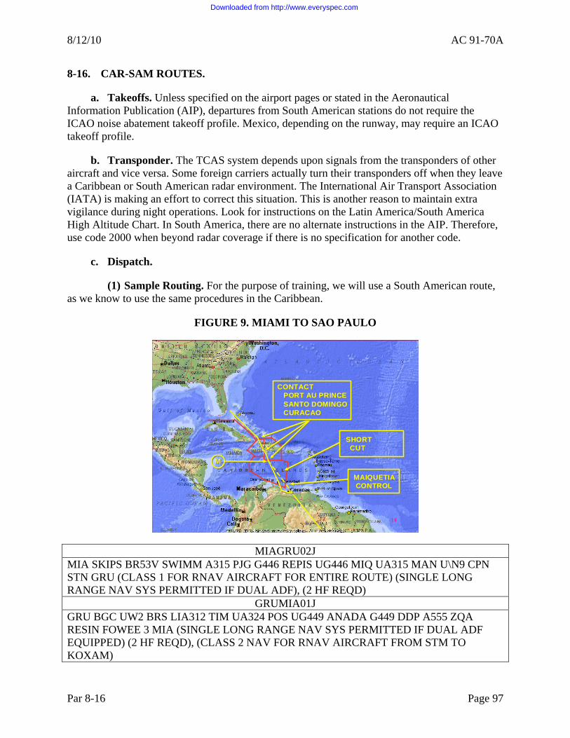
8/12/10 AC 91-70A
8-16. CAR-SAM ROUTES.
a. Takeoffs. Unless specified on the airport pages or stated in the Aeronautical Information Publication (AIP), departures from South American stations do not require the ICAO noise abatement takeoff profile. Mexico, depending on the runway, may require an ICAO takeoff profile.
b. Transponder. The TCAS system depends upon signals from the transponders of other aircraft and vice versa. Some foreign carriers actually turn their transponders off when they leave a Caribbean or South American radar environment. The International Air Transport Association (IATA) is making an effort to correct this situation. This is another reason to maintain extra vigilance during night operations. Look for instructions on the Latin America/South America High Altitude Chart. In South America, there are no alternate instructions in the AIP. Therefore, use code 2000 when beyond radar coverage if there is no specification for another code.
c. Dispatch.
(1) Sample Routing. For the purpose of training, we will use a South American route, as we know to use the same procedures in the Caribbean.
FIGURE 9. MIAMI TO SAO PAULO
1
CONTACT PORT AU PRINCESANTO DOMINGOCURACAO
CONTACT PORT AU PRINCESANTO DOMINGOCURACAO
SHORTCUT
SHORTCUT
MAIQUETIACONTROL
MAIQUETIACONTROL
MM
14
MIAGRU02J MIA SKIPS BR53V SWIMM A315 PJG G446 REPIS UG446 MIQ UA315 MAN U\N9 CPN STN GRU (CLASS 1 FOR RNAV AIRCRAFT FOR ENTIRE ROUTE) (SINGLE LONG RANGE NAV SYS PERMITTED IF DUAL ADF), (2 HF REQD)
GRUMIA01J GRU BGC UW2 BRS LIA312 TIM UA324 POS UG449 ANADA G449 DDP A555 ZQA RESIN FOWEE 3 MIA (SINGLE LONG RANGE NAV SYS PERMITTED IF DUAL ADF EQUIPPED) (2 HF REQD), (CLASS 2 NAV FOR RNAV AIRCRAFT FROM STM TO KOXAM)
Par 8-16 Page 97
Downloaded from http://www.everyspec.com

AC 91-70A 8/12/10
(2) South American Route Validation.
(a) The above represents typical routing between Miami and Sao Paulo. If this route requires a South American route validation, the FAA check airman should look for the following:
• Areas of Class II navigation. • Areas of in-the-blind broadcasts. • Areas of critical terrain depressurization escape routes. • FIRs. • Notes associated with FIR crossings. • Critical terrain areas. • ATC communication boxes. • Emergency airports.
(b) In this example, different southbound and northbound routes are required to achieve variety. Below is a presentation of the normal sequence of events along a specific route (02J) from Miami to Sao Paulo.
d. Southbound Flights. The first flight to receive a clearance will get the best altitude. Therefore, call clearance early and request your highest available FL for your weight. Flights tend to arrive at South American destinations at the same time. Holding may be necessary since the acceptance rate may be quite low compared to domestic airports.
e. Miami Center. Normal VHF with radar coverage until into the Port-au-Prince FIR. Expect clearance direct to ACMEE (not on LEGS page), direct JOSES.
f. Port-au-Prince Control. Contact at JOSES with standard position report. They will clear you direct Cabo Rojo (CRO) if requested.
g. Santo Domingo Control. Contact at least 10 minutes (VETMO) prior to FIR (CRO) for ATC clearance.
h. Curacao Control. Contact 5 minutes prior to VESKA. Request VESKA direct Cabo Codera (CBC). Expect change to Maiquetia Control east of Curacao (PJG) at the RR (REPIS).
i. Maiquetia Control. Has radar but normally requires position reports. Radar coverage extends from 150 miles north to 30 miles south of Maiquetia VOR (MIQ). Set one HF to Maiquetia Radio on 8855, 5526 or 10096 (SAM-2). Use Maiquetia Radio for ATC position reports if assigned VHF frequencies do not respond. Report LODIR, Canaima (CMA) and ISANI. Critical terrain escape routes exist in the vicinity of CIMA.
j. Manaus Center. Contact on VHF or above HF frequency. Expect the use of both VHF and HF ATC frequencies. Operations from TEPIM to TESAL require IFBP reports. You may lose VHF ACARS. Company communication is possible via SATCOM Voice or HF.
Page 98 Par 8-16
Downloaded from http://www.everyspec.com

8/12/10 AC 91-70A
k. Brasilia Center. Contact at TESAL. Expect radar contact south of TESAL. Brasilia Center controls flights all the way to Sao Paulo (GRU). Expect normal VHF handoffs.
l. FIR Boundaries. Unlike the United States, when crossing into airspace controlled by different countries, controlling agencies do not do handoffs efficiently or at all. It may be necessary to make a call in advance to the ATC facility for the national airspace you are approaching. The procedures for this communication are on the Jeppesen high charts for Miami, Port-au-Prince, Santo Domingo and Curacao. Identify the FIR boundaries on the chart. Then, locate the procedure associated with crossing. In most cases, a 10-minute advance call is adequate. Call on the proper frequency and give your estimate for the boundary fix and your FL. For example: “Curacao control, Aircraft 983 estimating VESKA at 0725, flight level 370.” Curacao replies: “Aircraft 983, report VESKA.” Make a full position report to the new facility when passing over that boundary fix.
(1) Contact New Facility. After making a position report to the old facility at the boundary fix, you will receive instructions to contact the new facility (the one you made the advance call to) on the appropriate frequency. As mentioned above, another position report will be necessary. Occasionally, a frequency change will be issued prior to reaching the boundary fix. In that case, wait until passing the boundary fix before giving a position report. A common practice is to advise the old facility prior to reaching the boundary that you are in contact with the new facility: “Santo Domingo control, Aircraft 983 estimating VESKA at 0725 and we are talking to Curacao.” This statement may accelerate the handoff.
(2) Complete Position Reports at Compulsory/Reporting Points. Some FIRs have radar. However, it is best to assume that they do not. Even when radar is available, the controllers may still expect you to make position reports. Unless instructed to omit all position reports or reports at specific fixes, make complete position reports at each compulsory/reporting point. Listen carefully to instructions from the controller as to which position to report next, if any.
m. ATC Separation. In South America, in a non-radar environment, separation between aircraft at the same altitude is based upon position reports to maintain 15 minute spacing. There is movement in getting the countries to work with 10 minute separation standards using certain RNAV routes. Expect this to be the standard in the future.
n. Northbound Flights. Once an operator files a flight plan in South America, it is very difficult to change. Call early for clearance so that there will be time to request any route changes if a delay or a low cruise altitude is assigned. For language problems, ask local operations for assistance. The first flight to receive a clearance will get the best altitude. If the departure SID does not agree with the flight plan, ask for clarification.
o. Low Altitude Cruise. Northbound flights are more likely to receive a cruise altitude clearance well below the optimum cruise altitude than southbound flights. This is the result of fewer converging airways in South America and the never-ending language difficulties with Spanish and Portuguese speaking air traffic controllers.
Par 8-16 Page 99
Downloaded from http://www.everyspec.com

AC 91-70A 8/12/10
p. Navigation. Circle Class II waypoints on the master Flight Plan Forecast. Then, check them against waypoints on the control display unit (CDU) LEGS page. Two independent verifications of course and distance “to each waypoint in Class II airspace” are required before entry. Do a position check within 2 minutes prior to each waypoint by comparing the FMC position with the Flight Plan Forecast waypoint latitude/longitude coordinates. Accomplish another verification of course and distance as you pass each waypoint with a line drawn through circled waypoints. When ATC announces, “radar contact,” it may suspend Class II navigation procedures. South America does not require position plotting. All southbound and northbound flights, regardless of the flight planned route, should have pre-departure and en route Class II navigation checks accomplished on them. En route NOTAMs may reveal NAVAIDs out of service, which can quickly change a Class I route into a Class II route. Use the following Class II checklist for South American operations:
• HF and SELCAL check.
• Compass deviation check.
• Air data inertial reference unit (ADIRU)/FMC gross error check.
• Navigation source validation.
• LDOC.
• VHF 123.45/121.5.
• Transponder 2000.
• Re-dispatch message RDA/IRU.
q. Miami Radio. A facility located at the Miami airport can now provide a strong HF and SELCAL check while at the gate in Miami. Use the following frequencies: 6637, 10033, 21964.
r. Caribbean Airports.
(1) El Salvador, San Salvador. The airport is at sea level and is right off the coast. Plan on flying the 15 distance measuring equipment (DME) arc to Runway 07. The airport lies among some agricultural fields and it might be hard to see until within 7 DME. Expect tower to clear you for the visual once you have the airport in sight. There is high mountainous terrain east of the airport.
(2) Freeport, Bahamas. Freeport International Airport (elevation 7 feet) is on Grand Bahamas Island. The island is relatively flat. However, there is an airspace restriction (MY (R)-3000) located 25 miles east of Freeport consisting of a tethered balloon, which rises to 15,000 feet.
(3) Georgetown, Paramaribo. The airport (elevation 95 feet) is 25 miles south of Georgetown. The land is low, marshy jungle with numerous small rivers. The terrain rises
Page 100 Par 8-16
Downloaded from http://www.everyspec.com

8/12/10 AC 91-70A
gradually away from the airport to the south and west reaching elevations of approximately 1,200 feet 60 miles to the south and 1,400 feet 55 miles to the west.
(4) Guatemala City, Guatemala. This is a special airport that requires an entry and an exit for part 121 operations before you can use it. The airport lies in a bowl with high terrain rising all around it. Good SA is imperative to a safe operation. For RWY 01, plan on using the instrument landing system (ILS) DME Arc. Proper speed control is necessary for executing a good approach, so do not exceed 170 knots. The FAA recommends using the autopilot (AP) for this approach. When making the final turn on from the 177 radial of AUR, turn initially to a heading of 330° and keep your track line just outside Vilan on the ND. If you turn too far inside Vilan, you cannot start down until you have the localizer. You will not get the localizer until well inside the final approach fix (FAF). The RWY 01 has a huge down slope at the approach end starting roughly 2,200 feet down the runway. If the airplane has not touched down by this point, execute a missed approach. You will be too far down the other end of the runway before you touch down and will not have enough room for stopping. Visually, there is a crevice at the approach end of RWY 01, giving the illusion that you are too low. For all the non-precision approaches, you must calculate a visual descent point (VDP). The minimum descent altitude (MDA) is usually reached at the VDP for a safe landing.
(5) Kingston, Jamaica. The airport (elevation 10 feet) is just south of Kingston on a narrow peninsula across the harbor. The highest elevation on Jamaica is approximately 7,400 feet and lies 13 miles ENE. of the airport.
(6) Mexico City, Mexico. The airport (elevation 7,341 feet) is on the central peninsula of Central America. The airport is in a bowl-like area with very high terrain rising rapidly around it. There is also an active volcano. SA is critical to a safe operation. The controllers speak English but will speak Spanish to Latin carriers. Expect to be at 250 knots when within 30 DME below FL 180. Arriving into Mexico City from the north or south, expect to have your Standard Terminal Arrival Route (STAR) and approach change frequently. Be careful not to be heads down on glass airplanes when it might be easier to fly raw data and avoid many changes to the FMC. If landing 5R, plan on going over System Management Office (SMO) VOR at a maximum speed of 200 knots for the arrival. From Mateo in-bound, a speed of 160 knots works well for the approach. You will be slowing down and going down at the same time so plan accordingly. ATS may ask you to maintain a higher speed until SMO. Remember you do not accept any clearance you cannot comply with. Give them an option (e.g., “Aircraft XXX maintain 250 knots until Mateo VOR.”) response: “Mexico City, Aircraft XXX cannot maintain two five zero knots until Mateo VOR. I can give you two zero zero knots until Mateo.” The controllers will comply with what you give them. You will also have a higher true airspeed (TAS) due to the elevation and climate. The turn to the final approach course is 110° and false localizer capture can occur. The FAA recommends capturing the localizer via raw data before arming the approach. Runway 5R has a displaced threshold and there is a tendency to dive for the runway. Stay on glide slope as long as possible. Tower may issue you a sidestep maneuver to 5L. Stabilized approach criteria are limits so be cautious accepting this clearance too low. Use maximum reverse thrust when able.
Par 8-16 Page 101
Downloaded from http://www.everyspec.com

AC 91-70A 8/12/10
Page 102 Par 8-16
(7) Montego Bay, Jamaica. The airport (elevation 4 feet) lies directly parallel to the coast and on the shoreline in a locally swampy area. Hills rise gradually in all directions, except for the ocean area, reaching 1,300 feet to 2,000 feet within 10 miles.
(8) Nassau, Bahamas. Nassau International Airport, elevation 10 feet, has relatively flat terrain.
(9) Port-au-Prince, Haïti. The airport (elevation 109 feet) is on a sharp indentation of the western shore of the island of Hispaniola. Elevations of almost 7,500 feet are 14 miles south of the airport, 9,000 feet 23 miles SE. and 4,600 feet 15 miles to the ENE.
(10) Port of Spain, Trinidad. The airport (elevation 57 feet) is approximately 12 miles ESE. of Port of Spain. The terrain is generally quite flat except for a mountain ridge extending east/west along the northern portion of the island, with elevations of 2,400 feet 5 miles north of the airport and almost 3,100 feet some 9 miles NNE. of the airport.
(11) Rock Sound, Eleuthera, Bahamas. Rock Sound International Airport, elevation 10 feet, has relatively flat terrain.
(12) San Jose, Costa Rica. The airport has high mountainous terrain on all sides. Expect to be held high on the approach with the runway visually sloping up. You will feel very high on the approach. Using 3:1 profile all the way down will let you know how high you are. For RWY 07 there is a 6,000-foot mountain just off your right on the approach as you are passing 6,000 feet. Stay on the localizer and do not deviate. Approaching the gate, keep your power on as there is a small upslope. For alternate airports, San Salvador is the closest and best response time.
(13) San Juan, Puerto Rico. Puerto Rico International Airport (elevation 10 feet) is on the northeastern shore of Puerto Rico. The terrain is generally level along the immediate coastal section, but a range of hills up to about 500 feet lies about 3 miles directly south of the airport. About 5 miles south are the foothills of an east-west range of mountains. Thirty-five miles SSW. terrain rises to almost 4,400 feet.
(14) Santo Domingo, Dominican Republic. The airport (elevation 58 feet) is on the south coast of the island of Hispaniola. The terrain in the immediate vicinity and to the east of the airport is flat. However, mountains rise to the north and west.
s. South American Airports.
(1) Buenos Aires, Argentina. SAEZ (EZE) - Ezeiza International Airport.
(2) Barranquilla, Colombia. The airport (elevation 94 feet) is about 5 miles south of Barranquilla. The terrain to the south and west of the airport is relatively flat but mountains begin their rise some 40 miles east of the field, reaching almost 19,000 feet 65 miles east of the airport.
(3) Caracas (Maiquetía), Venezuela. The airport (elevation 235 feet) is on the northern coast of South America. A range of mountains running parallel to the coastline rises
Downloaded from http://www.everyspec.com

8/12/10 AC 91-70A
abruptly from the airport with an elevation of approximately 9,100 feet 12 miles ESE. of the airport. There is also very high terrain immediately to the south, southeast and southwest of the airport. Use cockpit radar as a NAVAID backup during departures and arrivals.
(4) Maracaibo, Venezuela. The airport (elevation 213 feet) is on the western shore of the channel connecting Lake Maracaibo with the Gulf of Venezuela. The terrain in the vicinity of the airport is flat but mountains rise to an altitude of over 12,000 feet 90 miles west of the airport, and to over 6,500 feet 65 miles to the ESE. Terrain rises to almost 19,000 feet about 120 miles west of the airport.
(5) Montevideo, Uruguay. SUMU (MVD) - Carresco International Airport.
(6) Río de Janeiro, Brazil. The airport (elevation 30 feet) is on an island in the western extremity of a bay. It is in a bowl-like area, but immediately to the south, west and north, the terrain rises rapidly. To the SE., the mountain-ringed bay only provides one small opening to the sea. To the north of the airport at a distance of 20 to 30 miles lies a mountain barrier aligned east/west with peaks reaching 5,000 to approximately 8,000 feet.
NOTE: High terrain in this area requires close adherence to published procedures.
(7) Santiago, Chile. SCEL (SCL) - Arturo Merino Benitez International Airport.
(8) Sao Paulo, Brazil. SBGR (GRU) - Guarulhos International Airport Max gross weight departures from GRU will often require performance adjustments.
Par 8-16 Page 103 (and 104)
Downloaded from http://www.everyspec.com

Downloaded from http://www.everyspec.com

8/12/10 AC 91-70A
Par 9-1 Page 105
CHAPTER 9. GULF OF MEXICO OPERATIONS
9-1. INTRODUCTION. The Gulf of Mexico is unique in that it is international airspace that operates in some respects as U.S. domestic airspace. The Gulf of Mexico also encompasses restricted airspace around Cuba and the flight information regions (FIR) of Mexico as well as several smaller Caribbean countries.
9-2. CHARACTERISTICS OF THE AIRSPACE.
a. General. The airspace above and surrounding the Gulf of Mexico is complex and includes heavy concentrations of multi-altitude military operations, high altitude air carrier operations, and low altitude helicopter activity. There are numerous alert, warning, noise sensitive, and restricted areas: control zones, heavy concentrations of student pilot activity, and areas of communication and navigation unreliability.
(1) Long-Range Navigation System (LRNS) Operations. Any operation conducted in international airspace on an instrument flight rules (IFR) flight plan, visual flight rules (VFR)-controlled flight plan or at night and that continues beyond the published range of normal airways navigation facilities (non-directional radio beacon (NDB), very high frequency (VHF), VHF Omnidirectional Range (VOR)/distance measuring equipment (DME)) is considered to be a long-range navigation operation. Long-range navigation in a control area (CTA) requires operators to navigate the aircraft to the degree of accuracy required for the control of air traffic; that is, the aircraft should remain within one-half of the lateral separation standard from the centerline (CL) of the assigned track. The aircraft should also remain within the established longitudinal and vertical separation standards for the area of operation. You can find these separation standards in International Civil Aviation Organization (ICAO) Document 7030.
(2) ICAO Annex 2 Requirements for Flights Over High Seas. For flights conducted within international airspace under U.S. jurisdiction, FAA Order 7110.83, Oceanic Air Traffic Control Handbook, current edition, provides a simplified version of these separation standards. Title 14 of the Code of Federal Regulations (14 CFR) part 91, § 91.703(a) requires that civil aircraft must comply with ICAO Annex 2 when operating over the high seas. Annex 2 requires that “aircraft shall be equipped with suitable instruments and with navigation equipment appropriate to the route being flown.” In addition, Annex 6, Part II stipulates that an airplane operated in international airspace be provided with navigation equipment that will enable it to proceed in accordance with the flight plan and the requirements of the air traffic service (ATS). Annex 2 further requires that an aircraft will adhere to the “current flight plan unless a request for change has been made and clearance received from the appropriate air traffic control (ATC) facility.”
b. Control of Air Traffic. ATC of the airspace over the Gulf of Mexico is assigned to the Houston air route traffic control center (ARTCC). This center controls airspace within and outside of the U.S. air defense identification zone (ADIZ). The Houston CTA/FIR includes the airspace in the northern part of the Gulf of Mexico. This control extends southward from Houston Center’s coastal CTA to the middle of the Gulf in the vicinity of long. 24°30’ N. The Houston CTA/FIR borders Houston’s coastal control in the west and north and meets Miami’s oceanic CTA/FIR at lat. 86° W. in the east. The southern border of the Houston CTA/FIR is
Downloaded from http://www.everyspec.com

AC 91-70A 8/12/10
under the control of several Mexican FIR/upper control areas (UTA) and controlled by Havana CTA in the southeast. Conduct flight operations in this area in accordance with the applicable 14 CFR and ICAO Annex 2. Aircraft must have the navigation and communication equipment required for operations over the high seas installed and fully operational for flight in this airspace.
c. Flight Plans. Unless otherwise authorized by ATC, operators may not operate aircraft in oceanic airspace unless they file a flight plan. VFR operations in oceanic airspace are permitted only between sunrise and sunset at or below flight level (FL) 180. Although offshore airspace (the airspace between the U.S. 12-mile limit and the oceanic control area (OCA)/FIR boundary) permits VFR flights, operators commonly encounter instrument meteorological conditions (IMC). The FAA recommends that pilots hold an instrument rating, have an aircraft equipped for IFR flight, and file an IFR flight plan.
d. Alert Areas. Alert areas are areas wherein that contain a large volume of pilot training flights or unusual aeronautical activity. Conduct all activity within alert areas according to 14 CFR, without waiver, and you may not conduct any activity that may be hazardous to other aircraft. All aircraft within an alert area, both participating and nonparticipating, are equally responsible for collision avoidance.
e. Controlled Firing Areas. Controlled firing areas contain activities such as the firing of missiles and rockets, ordnance disposal, and static testing of large rocket motors. The users of these areas are responsible for immediate suspension of activities in the event that the activity might endanger non-participating aircraft. The controlled firing area locations in the Gulf of Mexico are in Notices to Airmen (NOTAM).
f. Key West International Airport. Title 14 CFR part 121 operations that land or depart from Key West International Airport must meet the special airport requirements of part 121, § 121.445.
g. Noise-Sensitive Areas. Noise-sensitive areas include outdoor assemblies of persons, churches, hospitals, schools, nursing homes, designated residential areas, and national park areas. As national park areas, wildlife refuges are noise-sensitive areas. Numerous wildlife refuges are along the U.S. coastline surrounding the Gulf of Mexico, and many of these refuges have large bird populations. The heaviest concentrations of these refuges are along the Texas and Florida coasts. VFR flights over noise-sensitive areas should be no lower than 2,000 feet above the surface, weather permitting, even if § 91.119 permits flight at a lower altitude. The surface is the highest terrain within 2,000 feet laterally of the route of flight or the uppermost rim of a canyon or valley.
h. Warning Areas. Warning areas are in international airspace and contain operations hazardous to non-participating aircraft. Pilots can receive IFR clearances through this airspace when hazardous operations are not taking place. Because there is no provision in international agreements for prohibiting flights in international airspace, there is no restriction on flights in these areas. However, pilots should take note of the location of all warning areas along a planned route.
Page 106 Par 9-2
Downloaded from http://www.everyspec.com

8/12/10 AC 91-70A
Par 9-2 Page 107
i. Restricted Areas. Title 14 CFR part 73 designates restricted areas to contain activities considered hazardous to non-participating aircraft. Aircraft may not operate within 3 nautical miles (NM) of a restricted area unless authorized under the provisions of part 73, § 73.13. There are numerous restricted areas near and along the Gulf of Mexico coastline. Pilots should be aware of these areas and plan flights accordingly.
9-3. NAVIGATION AND COMMUNICATIONS IN THE GULF OF MEXICO.
a. Background. ICAO Annex 6, Part II contains standards and recommended practices adopted as the minimum standards for all airplanes engaged in general aviation international air navigation. It requires those aircraft operated in accordance with IFR, at night, or on a VFR controlled flights (such as in CTA/FIR oceanic airspace) to have installed and approved radio communications equipment capable of conducting two-way communication at any time with the appropriate aeronautical stations on the prescribed frequencies.
b. High Frequency (HF) and VHF Communications. Due to the inherent “line of sight” limitations of VHF radio equipment used for international oceanic airspace communications, aircraft operating on an IFR or controlled VFR flight plan beyond VHF communications capability must maintain a continuous listening watch and communications capability on the assigned HF frequencies. Although ATC assigns these frequencies, actual communication will be with general purpose communication facilities such as an international Flight Service Station (FSS) or Aeronautical Radio, Inc. (ARINC). These facilities will be responsible for the relay of position reports and other information between the aircraft and ATC. Except in an emergency, the use of relay on VHF through aircraft operating at higher altitudes is not an acceptable method of communication with ATC.
c. Communication and Position Reporting.
(1) Non-available Communication. The following describes an area in the Houston CTA/FIR where direct air traffic communication is not available:
• N27°28’ W086°00’ to N27°30’ W087°42’ to; • N25°50’ W088°15’ to N25°37’ W091°55’ to; • N24°40’ W093°19’ to N24°28’ W088°01’ to; and • N24°00’ W086°00’ to beginning point.
(2) Communication Requirements. Pilots planning flights through this area should be aware of the communications and position reporting requirements. HF communications are available for all oceanic flights and limited VHF coverage is also available on 130.7 megahertz (MHz). The communication requirements for IFR flights within the Houston OCA are as follows:
• The aircraft must have functioning two-way radio communications equipment capable of communicating with at least one ground station from any point on the route.
Downloaded from http://www.everyspec.com

AC 91-70A 8/12/10
• The crew must maintain a continuous listening watch on the appropriate frequency.
• Make all mandatory position reports.
d. Position Reports. When flying an oceanic route in the Gulf of Mexico, position reports must be made over all designated reporting points. A position report must also be made upon crossing the FIR boundary. Unless otherwise required, reporting points should be located at intervals of 5 or 10° latitude (if flying north/south) or longitude (if flying east/west) either north or south of the equator or east or west of the 180° meridian. Aircraft transversing 10° of latitude or longitude in 1 hour 20 minutes should normally report at 10° intervals. Slower aircraft should report at 5° intervals. In the absence of designated reporting points, make position reports if instructed by ATC. Position reports are vital to air traffic safety and control. Inability to comply is a violation of 14 CFR and ICAO requirements.
e. Navigation Requirements.
(1) Class II Navigation in the Gulf of Mexico. You can conduct Class II navigation on routes in the Gulf of Mexico using Area Navigation (RNAV) with global position system (GPS), inertial reference systems (IRS)/inertial navigation system (INS), or VOR/DME sensors. NDB might also be available. These routes are offshore and shown on en route charts. FAA Order 7110.2, Procedures for Handling Airspace Matters, current edition, establishes the areas which serve aircraft operations between U.S. territorial limits, OCA/FIR boundaries, and/or domestic flights operating over the high seas. These transition CTAs permit ATC to apply domestic procedures and separation minimums. Because there is independent radar surveillance within these CTAs, separation minimums are not as large as for other OCAs. As long as you maintain radar surveillance, you may conduct operations on Gulf routes using RNAV, GPS, IRS/INS, VOR/DME, and NDB. Because of the proximity of these routes to shore-based facilities, using shore-based Navigational Aids (NAVAID) can enhance the accuracy.
(2) Single Long-Range Navigation System (S-LRNS). Approval for use of a S-LRNS on these routes, as well as the navigation techniques, are part of the authorizations (operations specifications (OpSpec), management specifications (MSpec), letters of authorization (LOA)) issued to air carrier operators.
f. Use of NDB for Navigation.
(1) Limitations and Restrictions. The use of NDB as a primary source of navigation on long-range flights presents the operator with numerous limitations and restrictions inherent in low frequency radio equipment and the low frequency signals they receive. NDB NAVAIDs of the highest power (2,000 watts or greater) that are maintained and flight checked as suitable for navigation are limited to a usable service and/or reception range of 75 NM from the facility at any altitude. Although the operator may be able to receive standard AM broadcast stations with NDB equipment, primary dependence on these facilities for navigation is a questionable operating practice. The following are some of the inherent problems associated with reception of these stations:
Page 108 Par 9-3
Downloaded from http://www.everyspec.com

8/12/10 AC 91-70A
Par 9-3 Page 109
• Infrequent station identification.
• Foreign language station identification may be impossible without knowledge of the language.
• Transmitter sites are not always with the studio facilities.
• Termination of service without notice.
• Weather or atmospheric disturbances may cause erratic and unreliable signal reception.
• Flight checks may not have been flown to verify the suitability and reliability of the facility and signal for navigation.
• The “shoreline/mountain” effect may cause signal fluctuations.
• Standard broadcast stations are not approved for navigation purposes.
(2) Evaluate NDB. Considering these limitations, the operator should be able to navigate so as to maintain the course specified in the ATC clearance. Carefully evaluate the inadequacies of NDB as the sole source of navigation as an error of 10° over 2,000 miles can result in a deviation of 350 miles.
9-4. INTERNATIONAL OPERATIONS.
a. Operations to Mexico. Pilots should be aware of the landing restrictions in effect at Mexico City Airport. Operators of aircraft that land or depart from this airport during peak hours will be charged a fee. Operators planning a flight to Mexico should check the NOTAMs for updated information. Part 121 operations to Guadalajara, Mexico must meet § 121.445 special airport qualification requirements.
b. Operations to Cuba. Section 121.445 requirements for special airport qualifications apply to part 121 operations landing or departing from Guantanamo Bay Naval Air Station. Operators should be aware that the Cuban government has issued a warning that Cuban armed forces will shoot down any aircraft that penetrates Cuban airspace without authorization and refuses to land for inspection.
c. Cuban Legal Considerations. Aircraft that receive orders to land or have landed without proper authorization will be subject to whatever penalties the Cuban authorities may prescribe, without recourse. The pilot and/or aircraft owner will be responsible for any damage, injuries or resulting expense. No aircraft may make an overflight carrying photographic equipment, arms, ammunition, explosives or other articles and substances the Cuban aeronautical authority may specify. The Cuban aeronautical authority will not authorize overflights if the operation constitutes a danger to air navigation or if, in their judgment, the operator does not offer adequate guaranties to cover any liability incurred because of the overflight. These liabilities include damage and loss caused to subjacent persons or property, and payment for any services rendered or obligations that may arise in connection with the overflight. The use of
Downloaded from http://www.everyspec.com

AC 91-70A 8/12/10
Cuban radio for flight information, ATC, or other purposes is considered a service and operators should expect to receive billing for its use. Any person or corporation, partnership, organization or association subject to U.S. jurisdiction and considering the operation of aircraft into Cuba must review current Department of Commerce and Department of State regulations relating to trade and other transactions involving Cuba. Within 1 hour of departure, the PIC must file an IFR flight plan and a written statement with the Immigration and Naturalization Service office at the departure airport. This statement must contain all of the information in the flight plan, the name of each occupant of the aircraft, the number of occupants in the aircraft (including the flightcrew), and a description of any cargo. The U.S. Naval airfield/facilities located at Guantanamo Bay, Cuba are unavailable to all civilian air traffic except for valid emergencies. U.S. authorities will thoroughly investigate all emergency landings to determine their validity and the nature of their business.
9-5. MILITARY AND HELICOPTER OPERATIONS.
a. Military Operations Areas. Military operations represent approximately one-third of the air traffic in the Gulf of Mexico. These operations include a high volume of non-hazardous training flights contained within Military Operation Areas. Military training routes (MTR) are on VFR and sectional maps. However, MTRs are subject to change every 56 days. Because the charts are only issued every 6 months, the FAA strongly advises pilots to contact the nearest FSS for current route dimensions and status.
b. Helicopter Operations. Pilots should be aware of the nature and extent of helicopter operations within the Gulf of Mexico. The density of helicopter traffic is primarily due to the presence of numerous oil rigs and drilling platforms in the Gulf. The majority of these flights are below 2,000 feet mean sea level (MSL) at varying distances from the coastline.
Page 110 Par 9-4
Downloaded from http://www.everyspec.com

8/12/10 AC 91-70A
CHAPTER 10. LONG RANGE NAVIGATION
10-1. GENERAL NAVIGATION CONCEPTS, FAA POLICIES, AND GUIDANCE.
a. General Concepts. In the early days of aviation, few aircraft operated within any given area at the same time. The most demanding navigational requirements were to avoid obstacles and arrive at the intended destination with enough fuel remaining to safely complete a landing. As aviation evolved, the volume of air traffic grew and a corresponding need to prevent collisions increased. Today, the most significant and demanding navigational requirement in aviation is the need to safely separate aircraft. There are several factors to understand concerning the separation of aircraft by air traffic control (ATC).
b. Separation of Air Traffic. In many situations, ATC does not have an independent means such as radar to separate air traffic and must depend entirely on information relayed from an aircraft to determine its actual geographic position and altitude. A flightcrew’s precision in navigating the aircraft is critical to ATC’s ability to provide safe separation. Even when ATC has an independent means such as radar to verify the aircraft’s position, precise navigation and position reports, when required, are still the primary means of providing safe separation. In most situations, ATC does not have the capability or the responsibility for navigating the aircraft. ATC relies on precise navigation by the flightcrew. Therefore, flight safety in all instrument flight rules (IFR) operations depends directly on the operator’s ability to achieve and maintain certain levels of navigational performance. ATC radar is used to monitor navigational performance, detect navigational errors, and expedite traffic flow. Any aircraft operating in accordance with ATC instructions must navigate to the level of accuracy required to comply with ATC instructions. Navigate aircraft with sufficient precision to avoid airspace where you must obtain prior ATC clearance or ATC instructions. For example, an aircraft flying adjacent to minimum navigation performance specification (MNPS) airspace must fly with a degree of precision that ensures that aircraft will not inadvertently enter MNPS airspace.
c. Visual Flight Rules (VFR) Flight. The control of air traffic requires VFR flights to achieve a certain level of navigational performance to ensure safe separation of aircraft and to expedite the flow of air traffic. During cruising flight, maintain the appropriate VFR flight altitude to ensure the required vertical separation between VFR and IFR aircraft and to assist in collision prevention. Navigate VFR aircraft with sufficient precision to avoid weather conditions that would prevent visual contact with (and avoidance of) other aircraft and to locate a suitable airport and land safely. VFR aircraft that require navigational assistance from ATC adversely affect ATC’s ability to control air traffic and expedite its flow.
d. The Concept of an ATC Clearance. Issuance of an ATC clearance by a controller, and the acceptance of this clearance by a pilot, is a negotiation process that establishes conditions for the prevention of collision hazards (in-flight and terrain). When a controller issues an IFR clearance, it reserves a three-dimensional block of airspace for that aircraft along the defined route. The controller also agrees to issue clearances to all other controlled air traffic to ensure safe separation of all assigned flight routes. When a pilot accepts an ATC IFR clearance, that pilot is agreeing to continuously remain within the assigned three-dimensional block of airspace and to adhere to the flight rules for that operation. This process obligates the pilot to comply with this agreement unless they declare an emergency or receive an amended clearance. Any
Par 10-1 Page 111
Downloaded from http://www.everyspec.com

AC 91-70A 8/12/10
deviation outside the assigned airspace creates a flight safety hazard. In such cases, the aircraft has failed to navigate to the degree of accuracy required for ATC and has failed to comply with Title 14 of the Code of Federal Regulations (14 CFR) and International Civil Aviation Organization (ICAO) requirements. In a non-radar environment, ATC has no independent knowledge of the aircraft’s actual position or its relationship to other aircraft. Therefore, when a deviation from an agreed upon clearance occurs, it seriously downgrades ATC’s ability to detect a navigational error and resolve collision hazards.
e. Concept of Navigation Performance. Maintain the concept of navigation performance that involves the precision for both the assigned route and altitude by an aircraft operating within a particular area. Navigation performance is measured by the deviation (for any cause) from the exact centerline (CL) of the route and altitude specified in the ATC clearance.
(1) Errors and Flightcrew Competency. This includes errors due to degraded accuracy and reliability of the airborne and ground-based navigational equipment and the flightcrew’s competence in using the equipment. Flightcrew competence involves both Flight Technical Errors (FTE) and navigational errors. FTE is the accuracy with which the pilot controls the aircraft as measured by success in causing the indicated aircraft position to match the desired position.
(2) Impact of Traffic Density on Navigation Performance. Standards of navigational performance vary depending on traffic density and the complexity of the routes flown. Different separation minimums applied by ATC in these two areas reflect the variation in traffic density. For example, the minimum lateral distance permitted between co-altitude aircraft in Chicago Center’s airspace is 8 nautical miles (NM) (3 NM when using radar), while in North Atlantic (NAT)/MNPS airspace it is 60 NM. The airspace assigned by ATC has lateral dimensions on both sides of the exact CL of the route of flight specified in the ATC clearance equal to one-half of the lateral separation standard (minimum). For example, the overall level of lateral navigation performance necessary for flight safety must be within 4 NM of the airway CL in Chicago Center’s airspace, and within 30 NM in NAT/MNPS airspace. Title 14 CFR part 121, §§ 121.103 and 121.121 require that each aircraft must be navigated to the degree of accuracy required for ATC. Part 91, § 91.123’s requirements related to compliance with ATC clearances and instructions also reflect this fundamental concept.
(3) ICAO Standards and Recommended Practices (SARP). The concept of navigational performance is also inherent in the ICAO SARPs. For example, Annex 2 states that the aircraft “shall adhere to its current flight plan” and “when on an established ATS route, operate along the defined CL of that route.” This is true unless the Strategic Lateral Offset Procedures (SLOP) are approved.
f. Degree of Accuracy Required.
(1) Control of Air Traffic. The fundamental concept for all IFR navigation standards, practices, and procedures is that you must navigate all IFR aircraft to the degree of accuracy required for control of air traffic. When a flight remains within the assigned three-dimensional block of airspace at all times, the IFR navigation standards, practices, and procedures will consider that the operator navigated that aircraft to the degree of accuracy required for the
Page 112 Par 10-1
Downloaded from http://www.everyspec.com

8/12/10 AC 91-70A
control of air traffic. If an aircraft deviates outside its assigned block of airspace (except during a declared emergency), the operator did not navigate that aircraft to the required degree of accuracy.
(2) Separation Minimums. ATC separation minimums represent the minimum dimensions of a three-dimensional block of airspace that ATC can assign to control flight. These separation minimums have been established for IFR operations in controlled airspace. These standards are usually established through international agreement and implemented through national regulations. These minimums are established for particular categories of navigational operation and specified areas. Examples include navigation on airways in the national airspace of ICAO member states and long-range navigation in oceanic or remote land areas. Separation minimums establish the minimum lateral, vertical, and longitudinal distances that can be used to safely separate aircraft operating within a specified area. Separation minimums also represent the minimum level of overall navigation performance which you can accommodate at any time without jeopardizing flight safety.
(a) Any aircraft deviating greater than one-half the separation minimums established for that operation has failed to meet the required level of navigational performance to the degree of accuracy required for control of air traffic. For example, the vertical separation minimum for airplanes operating above FL 290 in the United States is 1,000 feet. Each aircraft’s actual altitude must remain within +/- 240 feet of the assigned altitude even when considering factors such as atmospheric pressure variations and instrument or pilot errors. This is the Reduced Vertical Separation Minimum (RVSM) requirement. Where the United States provide Air Traffic Services (ATS), 14 CFR and ATC directives establish separation minimums. Where contracting ICAO member states provide ATSs, those state’s national regulations and ICAO documents establish separation minimums. Operations in uncontrolled airspace do not receive ATS, and separation minimums are not normally established for uncontrolled airspace.
(b) U.S. national airspace separation minimums can be found in the current edition of Federal Aviation Administration (FAA) Order 7110.65, Air Traffic Control. FAA Order 7110.83, Oceanic Air Traffic Control, current edition, prescribes separation minimums in international oceanic airspace delegated to the United States by ICAO. ICAO Document 7030, Regional Supplementary Procedures, current edition, prescribes separation minimums in international airspace.
g. Concept of Operational Service Volume. The concept of operational service volume is critical to understanding and applying the principles of air navigation. Operational service volume is the volume of airspace surrounding an ICAO standard airways navigation facility that is available for operational use. Within that volume of airspace, a signal of usable strength exists as co-channel interference does not operationally limit it. Within this volume of airspace, a Navigational Aid (NAVAID) facility’s signal in space conforms to flight inspection signal strength and course quality standards, including frequency protection. ICAO standard NAVAIDs are VHF Omnidirectional Range (VOR), VOR/distance measuring equipment (DME), and non-directional radio beacon (NDB). Global Navigation Satellite System (GNSS) is also an approved ICAO NAVAID and is applicable in both Class I and Class II navigation areas. The national airspace systems of ICAO contracting member states are based on the operational
Par 10-1 Page 113
Downloaded from http://www.everyspec.com
AC 91-70A 8/12/10
service volume of these facilities. You can predicate navigational performance within the operational service volume and ATC separation minimums on the use of these facilities.
h. Categories of Navigational Operations. A thorough comprehension of the categories of navigational operations is essential to understanding air navigation concepts and requirements, and in evaluating an operator’s ability to navigate to the required degree of accuracy. In the broad concept of air navigation, the following paragraphs identify two major categories of navigational operations.
i. Class I Navigation. Class I navigation is any en route flight operation conducted in controlled or uncontrolled airspace that is entirely within operational service volumes of ICAO standard NAVAIDs (GNSS, VOR, VOR/DME, and NDB). The operational service volume describes a three-dimensional volume of airspace which categorizes any type of en route navigation as Class I navigation. Within this volume of airspace, IFR navigational performance must be at least as precise as IFR navigation and must use GNSS, VOR, and VOR/DME (or NDB in some countries). The definition of Class I navigation is not dependent upon the equipment installed in the aircraft. En route a VFR flight navigated by pilotage is conducting Class I navigation when operating entirely within the operational service volume. However, the VFR navigational performance in this example must be as precise as VFR pilotage operations are required to be. The operational service volumes of ICAO standard NAVAIDs solely determine the lateral and vertical extent of airspace where you conduct Class I navigation. You cannot conduct Class I navigation outside of this airspace.
(1) VFR or IFR Navigation Operations. Class I navigation also includes VFR or IFR navigation operations on the following:
• Federal airways.
• Published IFR direct routes in the United States.
• Published IFR off-airway routes in the United States.
• Airways, Advisory Routes (ADR), direct routes, and off-airway routes published or approved by a foreign government provided that these routings are continuously within the operational service volume (or foreign equivalent) of ICAO standard NAVAIDs.
(2) Separation Minimums. Class I navigation requirements are directly related to separation minimums used by ATC. IFR separation minimums applied in the U.S. National Airspace System (NAS) and most other countries are based on the use of ICAO standard NAVAIDs. ATC, however, can only apply these separation minimums within areas where the NAVAIDs signal in space meets flight inspection signal strength and course quality standards. An ICAO standard NAVAID’s signal in space conforms to flight inspection signal strength and course quality standards (including frequency protection) within its designated operational service volume. Therefore, you can predicate air navigation and the safe separation of aircraft within that service volume on the use of these facilities.
Page 114 Par 10-1
Downloaded from http://www.everyspec.com

8/12/10 AC 91-70A
(3) Qualifications for Class I Navigation. Within areas where the safe separation of aircraft is based on the use of ICAO standard NAVAIDs, navigate any IFR operation with at least the same precision specified by the appropriate national separation minimums. Any operation or portion of an operation (VFR or IFR) in controlled or uncontrolled airspace with any navigation system (VOR, VOR/DME, NDB, inertial navigation system (INS) and GNSS) is Class I navigation for that portion of the route that is entirely within the operational service volume of ICAO standard en route NAVAIDs.
j. Class II Navigation. Class II navigation is any en route operation not categorized as Class I navigation and includes any operation, or portion of an operation, that takes place outside the operational service volumes of ICAO standard NAVAIDs. For example, an aircraft equipped with only VOR conducts Class II navigation when the flight operates in an area outside the operational service volumes of federal VORs/DMEs.
(1) Class II Navigation: Operating Outside the Operational Service Volume. Class II navigation involves operations conducted in areas where the signals in space from ICAO standard NAVAIDs do not meet flight inspection signal strength, course quality, and frequency protection standards. Therefore, ATC cannot predicate aircraft separation on the use of these facilities alone and must apply larger separation criteria. When operating outside the operational service volume of ICAO standard NAVAIDs, you cannot rely upon signals from these stations as the sole means of conducting long-range operations to the degree of accuracy required for the control of air traffic or as the sole means of obstacle avoidance. Therefore, when operating outside the designated operational service volumes of ICAO standard NAVAIDs, operators must use long-range navigation systems (LRNS) (GNSS, LORAN-C, INS/inertial reference system (IRS)) or other approved procedures which may include dead reckoning (DR), pilotage or flight navigator. These systems and/or techniques are necessary to navigate to the degree of accuracy required for the control of air traffic and to avoid obstacles. DR is a contingency procedure that you cannot plan.
(2) Class II Navigation Definition. The definition of Class II navigation is not dependent upon the equipment installed in the aircraft. All airspace outside the operational service volume of ICAO standard NAVAIDs is a three-dimensional volume of airspace within which any type of en route navigation is Class II navigation. For any type of navigation within this volume of airspace, the IFR navigational performance must be as precise as the navigational performance assumed during establishment of the ATC separation minimums for that volume of airspace. The navigational performance for VFR operations in a Class II navigation volume of airspace must be only as precise as VFR navigation operations are required to be.
(3) Class II Requirements. It is possible in turbojet airplanes, with proper procedures and training, to fly many routes between the southeastern United States, Caribbean Islands, and South America with VOR/DME and NDB equipment. In these situations, you can meet Class II navigation requirements even though significant portions of these routes, less than 1 hour, are outside the operational service volumes of ICAO standard NAVAIDs. In the domestic United States, it is not uncommon for low altitude VFR flights in aircraft such as helicopters to conduct Class II navigation while outside the operational service volumes of ICAO standard NAVAIDs when operating over routes of less than 100 NM in length. Class II navigation includes transoceanic operations and operations in desolate/remote land areas such as the Arctic.
Par 10-1 Page 115
Downloaded from http://www.everyspec.com

AC 91-70A 8/12/10
Page 116 Par 10-1
(4) Class II Navigation NAVAIDs. Class II navigation does not automatically require the use of LRNS. In many instances, you can conduct Class II navigation with conventional NAVAIDs if special navigational techniques supplement these NAVAIDs. Any portion of an en route operation in controlled or uncontrolled airspace, with any navigation system or any navigation technique, is Class II navigation for that portion of the route that is outside the operational service volumes of ICAO standard en route NAVAIDs.
10-2. IRS/INS AND LONG-RANGE NAVIGATION PROCEDURES.
a. Background. Recently, an aircraft deviated approximately 60 miles from an assigned NAT track and came within a few feet of colliding with an aircraft assigned to an adjacent track. Following the near miss, the aircraft that had deviated from its track did not follow established contingency procedures for aircraft experiencing navigational uncertainty, thus creating the potential for further conflict with other aircraft as it returned to its assigned track. The crew’s failure to operate the navigation equipment in a disciplined systematic manner during all phases of flight caused the incident. The crew’s failure to comprehend the relationship between navigation performance, contingency procedure, and collision avoidance further complicated the incident.
(1) Navigation and Human Errors. Although navigation errors are infrequent, human errors account for a majority of the errors attributed to aircraft equipped with automated systems. Most inadvertent navigation errors have occurred when the equipment was functioning normally, but the operating procedures prescribed were either inadequate or the operator did not follow them. Experience indicates that the increased accuracy and reliability of modern automatic navigation systems can induce a degree of complacency on the part of flightcrews, and may result in failure to routinely cross-check system performance. Under these circumstances, human errors may remain undetected for excessive periods. A common error associated with automated systems is incorrect programming of the oceanic waypoint latitudes by multiples of 1° (60 NM). In an organized track system (OTS), this can result in the flight maintaining a wrong track with high precision and thereby constituting a serious threat to other aircraft properly occupying that track and FL. Vigilance and diligence in properly applying established procedures are essential to safe oceanic navigation. Although operational procedures may differ among navigation systems, many good practices and procedures are basic to all automated and semi-automated systems.
(2) Practices and Procedures for IFR Long-Range Navigation Operations. IFR long-range navigation operations using pilot-operated electronic long-range navigation equipment should use the practices and procedures recommended in this document. Prior to issuing operations specifications (OpSpecs) authorizing operations requiring long-range navigation equipment, the FAA principal operations inspector (POI) should ensure that the operator’s training program, manuals, and check airman program include and emphasize these practices and procedures. For operations currently authorized by OpSpecs or a letter of authorization (LOA), review the operator’s navigation program to ensure that it follows the guidance contained in this AC. The Flight Technologies and Procedures Division, AFS-400, must approve any deviation from these requirements.
Downloaded from http://www.everyspec.com

8/12/10 AC 91-70A
b. Weather. In addition to the normal review of weather information concerning terminals, crews should be alert for hazardous weather that may require a flight plan change or in-flight re-routing. It is important to obtain a copy of the wind flow chart (constant pressure chart or the equivalent) for the FL and the route flown. This information may be valuable when evaluating wind forecasting errors or if DR operations become necessary due to equipment failure. As the flight progresses, give consideration to plotting actual wind information on the plotting chart as a means of evaluating the accuracy of the forecast.
c. Notices to Airmen (NOTAM). Besides checking NOTAMs for departure, destination and alternate airports, check NOTAMs concerning NAVAIDs or special airspace restrictions along the planned route.
d. Waypoint Management. The navigation program should include a standard system for indicating waypoint status as detailed below. The specific procedures recommended are in the list below. Variations in specific symbols may be necessary to accommodate the individual operator’s program.
• The crew stores the waypoint coordinates in the computer. (Enter the waypoint number next to the relevant waypoint coordinates.)
• A second crewmember independently cross-checks the coordinates and zone distances. (Circle the waypoint number.)
• The second crewmember cross-checks the coordinates and zone distances during the approaching waypoint check. (Draw a diagonal line through the waypoint number.)
• Waypoint passage has occurred. (Draw a second diagonal line through the waypoint number.)
• Cross-checking during all phases of flight. (Flight planning, preflight, en route.)
• Official (master) document.
• Plotting.
e. Plotting Procedures. Use of plotting procedures has had a significant impact on the reduction of gross navigation errors (GNE). All flights using long-range navigation equipment as the sole means of navigation require the use of this technique to plot the flight route on a plotting chart and to plot the computer position approximately 10 minutes after waypoint passage. Routes of shorter duration that transit airspace where special conditions exist, such as reduced lateral separation standards, high density traffic, or proximity to potentially hostile border areas may require the use of plotting procedures. All turbojet operations where the route segment between the operational service volume of ICAO standard NAVAIDs, VOR, VOR/DME, and NDB exceed 725 NM and all turboprop operations where the route segment between the operational service volume of ICAO standard NAVAIDs exceeds 450 NM require plotting procedures. The operational service volume is that volume of airspace surrounding a NAVAID which is available
Par 10-2 Page 117
Downloaded from http://www.everyspec.com

AC 91-70A 8/12/10
for operational use, within which a signal of usable strength exists, and where co-channel interference does not operationally limit that signal. You can determine the operational service volume for a specific NAVAID by contacting the Frequency Management Section within each regional Airway Facilities Division. Operational service volume includes the following:
• The officially-designated standard service volume excluding any portion of restricted standard service volume.
• The extended service volume.
• Within the United States (including offshore control areas (CTA)) by published instrument flight procedures (Victor or jet airways, standard instrument departures (SID), Standard Terminal Arrival Routes (STAR), Standard Instrument Approach Procedures (SIAP) or instrument departure).
• Outside the United States, any designated signal coverage or published instrument flight procedure equivalent to U.S. standards.
f. Flight Planning. Many operators use a computerized navigation flight plan. Take care to verify that all en route waypoints are correct and legibly shown on the flight plan. It is good practice to select a waypoint loading sequence and number each waypoint accordingly. If using more than one copy of the flight plan, designate one copy as the official copy. To eliminate possible confusion, ensure that all necessary information, routing changes, estimated time of arrival (ETA), and waypoint loading sequence is on this flight plan, and use the official copy for all reports to ATC. Additionally, if the flight is within the North Atlantic Organized Track System (NAT OTS), obtain a copy of the current track message and be alert for conflict between the flight plan and the track message. Track messages are issued approximately every 12 hours and describe the NAT routes, gateways, and FLs available for eastbound and westbound flights during the period indicated. While planning an over-water flight, pilots should review NOTAMs for any condition that may affect the operation and accuracy of LRNSs. Approach the use of heading information for cross-checking with caution. In steering a given route segment with a navigation computer, the true heading required to maintain a Great Circle course will change. For example, the true heading to maintain the Great Circle course from 50°N. 30°W. to 50°N. 40°W. will be 274° at 30°W., 270° at 35°W., and 265° at 40°W. Differences in variation along the route will further change the magnetic heading required to maintain course. The flightcrew must have a thorough understanding of the flight plan heading information and DR technique in order to use this check with any degree of certainty.
g. Navigation Preflight (at Aircraft). Verify navigation system software identification and modification status codes. Cross-check inputs to navigation computers. One crewmember should carry each insertion out in its entirety and another should recall and verify it. Cross-check computer flight plan zone distances with zone distance displayed in navigational computers. Perform the cross-check of coordinates and zone distances on all computer systems individually when using the remote loading feature. For INS, after placing the systems in the navigation mode, check the groundspeed while the aircraft is stationary. A reading of more than a few knots may indicate an unreliable system.
Page 118 Par 10-2
Downloaded from http://www.everyspec.com

8/12/10 AC 91-70A
• Cross-check computer flight plan, waypoint coordinates and identifiers with source documents (airfield diagrams, en route charts, and NAT track messages, if applicable).
• Plot the flight route on a chart of appropriate scale. Operational experience has demonstrated that a scale of 1 inch to 120 NM provides the most benefit for plotting purposes.
• Compare routing information on ATC flight plans, computer flight plans, NAT track messages, plotting charts, aircraft observations and Aircraft Report (AIREP) forms.
• It is advisable not to copy waypoint coordinates from source documents (track message, en route charts, etc.) to the flight plan for subsequent insertion into the navigation computers. To avoid errors in transcription, insert waypoint coordinates into the computers directly from the source documents.
• Since the initial stage of the flight can be very busy, give consideration to ensuring the navigation system waypoint transfer switches are in the “auto” position to facilitate outbound tracking and waypoint changeover during this period.
• With systems such as INS that navigate during ground operations, it is advisable to cross-check present position, taxi distance or groundspeed (as appropriate) prior to takeoff to confirm proper system operation and to ensure that the present position remains accurate.
h. Equipment Preflight. In addition to operating procedures such as checklists for confirming proper system operation, take care to ensure the proper programming of the navigation equipment. This is a very important procedure and you should not rush it. All navigation information, coordinates, or courses and distances should be programmed by one crewmember and verified by another. In addition, crews should verify that each system uses the same waypoint loading sequence and indicate on the flight plan that the crew entered cross-checked the present position, if applicable, and waypoints. If time becomes a factor, it is more important to verify that the first two or three waypoints are correct than to rush through the procedure to insert as much information as possible. Give consideration to using another cross-check that compares the flight plan or charted distance between waypoints and the distance computed by the navigation system to detect programming or flight planning errors. This serves as a double check on waypoint verification and will also reveal any error in the flight plan. A difference of more than 2 NM may indicate a programming or flight planning error.
i. Pre-Takeoff and Coast Out. Before takeoff, cross-check the computer present position to confirm proper system operation. At least two crewmembers should copy and confirm the oceanic clearance. Perform accuracy check to compare navigation computer position with VOR, VOR/DME or NDB. Direct overflight of a NAVAID and for cases when you do not directly overfly the NAVAID apply the NAV accuracy check. Record the gross error in the flight log. When outbound from gateway, cross-check VOR, VOR/DME, or NDB course and distance information with navigational computers. Use a compass deviation check (INS only) for
Par 10-2 Page 119
Downloaded from http://www.everyspec.com

AC 91-70A 8/12/10
contingency DR and for determining which system is correct when there is disagreement between systems.
j. Within Range of the Outbound Gateway. Flights should not continue beyond the outbound gateway unless the required long-range navigation equipment is functioning properly. To confirm proper operation, certain cross-checks should be performed while within range of the gateway NAVAID. Since this may be the last positive position cross-check until the inbound gateway, the following practices may also provide valuable information for resolving any later navigation difficulties.
(1) ATC Clearances. Two crewmembers should cross-check all ATC oceanic clearances to ensure the clearance is copied correctly. Cross out any flight plan waypoints that were revised in an ATC clearance and enter the revised coordinates in a legible manner. Prior to proceeding outbound from the gateway, compare the current ATC clearance to the flight plan and the information in the navigation computers for the gateway and verify the subsequent waypoints. Verify and change (if necessary) the clearance track on plotting chart.
(2) Gross Error Check. A gross error check is a position accuracy cross-check using normal airway facilities such as VOR, VOR/DME or NDB. The operator usually accomplishes the gross error check by flying directly over the gateway (if possible) and subsequently establishing the aircraft on the outbound course using the gateway NAVAID. This check detects errors that may have accrued in position information since takeoff, provides information used to determine the most accurate system for use as a steering reference, and provides an opportunity to correct position information. The gateway check also confirms that the operator establishes the aircraft on the outbound course and is tracking toward the next waypoint.
(3) Flight Instruments Used for Display. When operators use flight instruments for the display of either airways (VOR) information or information from the LRNS, they should leave the “radio/nav” switches in “radio” position after passing over the gateway NAVAID until the radio information becomes degraded. Operators should then place switches in the “nav” position.
(4) Compass Deviations. Give consideration to performing a compass deviation check on systems such as INS that use true heading information from sources independent of the aircraft compass system. You can determine the compass deviation by comparing the INS derived data later in the flight to determine the most accurate system should a divergence between systems occur. You can apply the compass deviations to the respective compasses to determine the actual magnetic heading. Operators can apply local variation to the true heading of each INS to obtain the derived magnetic headings. The most accurate INS should be the one with a magnetic heading that compares the most favorably with the actual magnetic heading.
k. After Passing the Gateway. Select the system determined to be the most accurate during the gross error check as the autopilot (AP) steering reference. When not used for other purposes, this system should display present position. Routinely check cross-track, track angle error (TKE) and distance-to-go. Display computer position coordinates and compare with ATC clearance to confirm that you maintained track CL.
Page 120 Par 10-2
Downloaded from http://www.everyspec.com
8/12/10 AC 91-70A
Par 10-2 Page 121
l. Approaching Waypoint. Within 2 minutes of each waypoint, both pilots should verify that the subsequent waypoint in the ND agrees with the current ATC clearance. Cross-check coordinates of the approaching waypoint and subsequent waypoints. Compare zone distance on the flight plan to that displayed on the navigation computer for the next leg. Compare computer flight plan ETA with ETA information displayed in navigation computers. (On some systems, you may accomplish this cross-check more easily during waypoint passage.)
m. After Passing Each Waypoint. Approximately 10 minutes after passing each waypoint, plot the present position information on the NDs on a navigation chart to confirm that the ATC clearance is satisfied. Confirm that the navigation systems have switched to the next flight segment (leg change). Verify that the aircraft is tracking along the next flight segment (tracking outbound).
n. Approaching the Inbound Gateway. Make certain preparations for the transition from long-range navigation to airways navigation. The FAA recommends the following practices:
• As soon as feasible, set up the navigation radios to receive the inbound gateway NAVAID.
• When the gateway NAVAID is providing reliable information, place the “radio/nav” switch in the “radio” position and steer the aircraft to acquire and maintain the proper inbound radial/bearing.
• Unless otherwise directed by ATC, fly the aircraft directly over the gateway.
• When over the gateway, record the position information from the navigation displays (ND). You can use this information to confirm system accuracy. Compare VOR, VOR/DME, NDB course and distance information with that displayed in navigation computers. The FAA recommends that you make system accuracy computations after arrival to avoid conflicts with other cockpit duties during the critical periods of descent, approach and landing.
o. After Arrival. Compute and record the individual navigation system errors and error rates (if applicable) for future reference. It is desirable to record this information in a document that remains aboard the aircraft to provide subsequent flightcrews with a recent history of system performance. This information may be used with most systems to predict individual system performance for future flights under similar circumstances. Additionally, this information may prove valuable to subsequent flightcrews for resolving navigation abnormalities, such as divergence between systems.
10-3. LRNS PROBLEMS AND RECOMMENDED ACTIONS. Although the accuracy and reliability of the newer navigation systems are excellent, malfunctions and failures occasionally occur. When a malfunction occurs, flightcrews should guard against jumping to conclusions since hasty actions are seldom necessary and may further complicate the situation. Experience has shown that successful resolution of navigation difficulties in oceanic areas usually requires a thorough, thoughtful process that normally begins during preflight planning.
Downloaded from http://www.everyspec.com

AC 91-70A 8/12/10
The training program manuals and check airman program for air carrier operations should emphasize procedures followed in the event of partial and total instrument failure. Non-air carrier operators should be able to demonstrate this emphasis in their training programs if requesting an LOA for oceanic operations in special airspace. The following guidance is for consideration when encountering or suspecting navigation difficulties.
a. Navigation Errors. Monitoring procedures used during oceanic operations indicate the frequency and course of navigation errors. Considering that operators make thousands of flights, errors are actually rather infrequent. Navigation systems are generally so reliable that there is some concern about overconfidence. Therefore, crews should guard against complacency.
(1) Frequent Causes of Errors. Frequent causes of errors include the following:
• Making a mistake of 1° of latitude when inserting a forward waypoint.
• The crew received re-clearance by ATC but forgot to re-program the navigational system.
• The operator left the AP in the heading or de-coupled position after avoiding severe weather or they left it in the VOR position after departing the last domestic airspace VOR. In some cases, this occurred after distractions by selective calling (SELCAL) or flight deck warning indications.
• The controller and crew had different understandings of the clearance because the pilot heard what he/she wanted to hear rather than what they actually said.
(2) Rare Causes of Errors. Rare causes of errors include the following:
• The latitude/longitude coordinates displayed at the gate position were incorrect.
• Because of a defective chip in an aircraft system, and although the crew inserted the correct forward latitude, it “jumped” 1°. (INS only.)
• The aircraft has an advanced system that includes all waypoint coordinates already in the database equipped. The crew assumed the coordinates were correct, but one was not.
• Although the crew had the correct coordinates available, the information inserted into the system was from an incorrect company flight plan.
b. Detection of System Failure. In general, we usually consider system failure to have occurred when one of the following situations develop:
• Activation of a warning indicator that cannot be reset;
• Self-diagnostic or built-in test equipment (BITE) indicates that the system is unreliable;
Page 122 Par 10-3
Downloaded from http://www.everyspec.com

8/12/10 AC 91-70A
• The position error over a known geographic location exceeds the maximum permissible tolerance established for a particular navigation system; or
• The system’s operation is so abnormal that, despite the absence of warning or malfunction indications, the flightcrew considers the system no longer useful for navigation.
c. Detection of System Degradation or Malfunction.
(1) Identifying a Faulty System. While system failures are usually straight forward, malfunctions or gradual system degradations are usually more difficult to detect. This is particularly true when only two systems are onboard. A divergence between the navigation systems, a situation that often occurs gradually, usually detects navigation difficulties of this type. This factor may reduce the possibility of identifying the faulty system unless operators diligently use periodic cross-checking practices. Consider the following factors when attempting to identify a faulty system:
• Check the BITE codes for indications of system fault.
• Review the gateway gross error check for indications of the most accurate system.
• If you maintain a regular record of system performance and it is available, a review of the record may give a clue as to which system is faulty.
• If possible, use VOR, automatic direction finder (ADF), DR, airborne radar, or other NAVAIDs to obtain a position fix.
• Cross-check heading, groundspeed, track, and wind information between systems and compare this information with the best known positive information such as position over a fix.
• Attempt to contact nearby aircraft to obtain wind or groundspeed and drift correction information that may identify the malfunctioning system.
• The compass deviation check may provide a clue as to which system is faulty for systems such as INS.
(2) Determining a Faulty System. Even though you take these steps, a divergence between systems may occur, but the flightcrew may be unable to determine which system is at fault. When this occurs, use the practices described in the following paragraph.
d. Recommended Actions Following System Failure. After detecting a system malfunction or failure, inform ATC that the flight is experiencing navigation difficulties so that you can adjust the separation criteria, if necessary. Reporting malfunctions to ATC is an ICAO requirement and 14 CFR part 91 requires compliance. If you can identify the failed system with a high degree of confidence and the other system appears normal, the best course of action may be
Par 10-3 Page 123
Downloaded from http://www.everyspec.com
AC 91-70A 8/12/10
Page 124 Par 10-3
to fly the normal system and carefully monitor its performance using any additional NAVAIDs available. In the unlikely event that a total navigation failure occurs and other aids are unavailable, the only action may be to fly by contingency DR using the flight plan headings and times. Under these circumstances, flightcrews should continue to use all means available to obtain as much navigational information as possible. Flightcrews should be alert for visual sightings of other aircraft, since a hazard may exist due to an inadvertent deviation from the assigned track. In some cases, it may be possible to establish and maintain visual contact with another aircraft on the same track.
e. Recommended Action Following a Divergence Between Systems. Since a small divergence between systems may be normal, evaluate the significance of the divergence. In general terms, if the divergence is less than 10 NM, the best course may be to closely monitor system performance and continue to steer the system considered most accurate. If the divergence between systems is greater than 10 NM, it may degrade one of the systems. Therefore, make attempts to determine which system may be faulty. If you cannot determine the faulty system using the practices described in this section, and both systems appear normal, the action most likely to limit gross tracking error may be to position the aircraft so that the actual track is midway between the cross-track differences for as long as the position uncertainty exists. Advise ATC that you are experiencing navigation difficulties so that you may adjust separation criteria as necessary. Give consideration to abandoning this “split-the-difference” practice if the divergence exceeds the separation criteria currently in effect on the route of flight. If a divergence of this magnitude occurs and you cannot isolate the faulty system, the best course may be to fly by contingency procedures using the best known wind information. However, in some cases, the best known information may be flight plan headings and times.
10-4. PROVING TESTS AND VALIDATION FLIGHTS. Title 14 CFR parts 121 and 135 require evaluation of an operator’s ability to conduct operations safely and in accordance with the applicable regulations before issuing an operating certificate or authorizing a certificate holder to serve an area or route. The testing method used by the FAA to determine an operator’s capabilities are validation flights. Sections 121.93, 121.113, and 135.145 require an operator to demonstrate the ability to conduct operations over proposed routes or areas in compliance with regulatory requirements before receiving FAA authority to conduct these operations. The FAA requires validation flights for authorization to add any areas of operation beyond the continent of North America and Mexico, and before issuing authorization for special means of navigation. Though proving tests and validation flights satisfy different requirements, it is common practice for operators to conduct both tests simultaneously. However, validation flights are important to consideration of oceanic operations (14 CFR part 119, § 119.59).
a. Validation Flights. Sections 121.93, 121.113, and 135.145 require operators to show the capability to conduct line operations safely and in compliance with regulatory requirements before receiving authorization to conduct those operations in revenue service. The most common method of validating an operator’s capability is to observe flight operations. The FAA normally requires validation flights before issuing OpSpecs granting authority to conduct operations beyond the populated areas of the North American (NAM) continent. When the FAA conducts a validation flight, they conduct an in-depth review of the applicable portions of the operator’s proposed procedures, including flight following, training programs, manuals, facilities, and maintenance programs. There are four situations that require validation flights in association
Downloaded from http://www.everyspec.com

8/12/10 AC 91-70A
with approval of Class II navigation: initial approval; addition of an LRNS or a flight navigator; operations into new areas; and addition of special or unique navigation procedures. Validation flights are required when an operator proposes to conduct operations that require confirmation of the ability to operate an aircraft type within specified performance limitations. These limitations are based on the character of the terrain, extended over-water, the type of operation, and the performance of the aircraft. Validation flights are also required when an operator proposes to conduct in-flight or ground maneuvers that require special operational authorizations.
b. Carriage of Revenue Passengers on Validation Flights. Title 14 CFR does not forbid the carriage of revenue passengers on validation flights. The operator may receive FAA authorization to carry revenue passengers during the validation flight when the proposed operation is similar to those in the applicant’s previous experience. However, validation flights do not normally permit the carriage of revenue passengers in the following situations:
• When the operator is seeking initial approval to conduct Class II navigation in any airspace designated as a special area of operation;
• When the operator is seeking approval to conduct Class II navigation by an LRNS or by using a flight navigator not previously approved for that means of navigation;
• When the operator is seeking approval to conduct Class II navigation by means of a long-range navigation procedure not previously approved for that operator; and
• When the operator has not previously operated a specific aircraft type in operations requiring special performance authorization.
c. Special Areas of Operation (SAO). Certain areas of Class II airspace are considered special operating airspace for purposes of validation. These areas include the following:
• Northern Canadian areas of magnetic unreliability;
• NAT/MNPS airspace and Canadian MNPS airspace;
• Central Pacific (CENPAC) composite airspace and Northern Pacific (NOPAC) airspace;
• Arctic Ocean and Antarctic airspace; and
• Politically sensitive areas of operation.
d. Special Navigation Procedures. Validation flights are normally required when an applicant proposes to use navigation procedures not previously demonstrated. These procedures include the following:
• Pilotage, including DR;
• Flight navigator procedures;
Par 10-4 Page 125
Downloaded from http://www.everyspec.com

AC 91-70A 8/12/10
Page 126 Par 10-4
• Celestial navigation;
• Pressure pattern and Bellamy drift DR;
• Free gyro or grid procedures; and
• Any combination of the preceding procedures.
e. Other Situations Requiring Validation Flights. Special operational authorizations and special performance authorizations may also require validation flights. The FAA encourages operators who require additional information on validation flights to contact their local FAA Flight Standards District Office (FSDO).
10-5. INS NAVIGATION—SPECIAL PRACTICES AND PROCEDURES.
a. Preflight. Since INS is a self-contained device and not a position fixing device, it will retain and possibly increment any error induced during alignment throughout the flight unless you remove it through updating procedures. Therefore, during preflight, exercise care to ensure that you insert the accurate present position information into the INS. Although most INSs will automatically detect large errors in present position latitude during alignment, large errors in present position longitude may exist without activating a warning indication. When cross-checking present position coordinates, be alert for the correct hemispheric indicator (that is, N., S., E., W.) as well as the correct numerical values. Since you cannot realign most INSs in-flight, it may require special procedures such as ground realignment to correct a significant error in present position. If the INS in use has the capability of “gang-loading” (simultaneous loading) by use of a remote feature, take care so that you cross-check any data entered by this method separately on each individual INS to detect data insertion errors. Verify the INS software identification and modification status codes to ensure installation of the proper equipment and utilization of the appropriate operating checklist. The operating checklists should include a means of ensuring that the INS is ready to navigate and that the operator activated the navigation mode prior to moving the aircraft. Any movement of the aircraft prior to activating the navigation mode may induce very large errors that only ground realignment can correct. After placing the system in the navigation mode, check the INS groundspeed when the aircraft is stationary. An erroneous reading of more than a few knots may indicate a faulty or less reliable unit. If this occurs, check the malfunction codes.
b. In-Flight Updating. INS is essentially accurate and reliable, but it is possible to introduce errors in an attempt to improve accuracy by in-flight updating. On the other hand, INS errors generally increase with time and are not self-correcting. If large tracking errors occur, they may significantly degrade aircraft safety and separation criteria. Consider these factors in any decision relative to in-flight updating. As a guide to flightcrews, some operators consider that unless the ground facility provides a precise check and unless the error is fairly significant (for example, more than 6 NM or 2 NM/hour), it is preferable to retain the error rather than update.
Downloaded from http://www.everyspec.com

8/12/10 AC 91-70A
10-6. FAA APPROVAL OF GLOBAL POSITIONING SYSTEM (GPS) EQUIPMENT AND OPERATIONS.
a. Portable Units. Handle all portable electronic systems and portable GPS units in accordance with § 91.21. The operator of the aircraft must determine that each portable electronic device they use the aircraft they operate will not cause interference with the navigation and communications systems. Mount yoke mounts usually sold with a portable GPS unit to prevent interference with the operation of the aircraft controls. Install permanent mounts and externally mounted antennas for use with a portable GPS unit in a FAA-approved manner. A critical aspect of any GPS installation is the installation of the antenna. Shadowing by the aircraft structure can adversely affect the operation of the GPS equipment. Electrical noise or static in the vicinity of the antenna can adversely affect the performance of the system. Use portable GPS receivers as a supplemental aid to VFR in conjunction with an approved primary means of navigation.
b. GPS Equipment Classes. GPS equipment is categorized into classes A, B, and C (ref. TSO-C129, TSO-C129A, TSO-C145, and TSO-C146).
(1) Class A. Equipment incorporating both the GPS sensor and navigation capability. This equipment incorporates receiver autonomous integrity monitoring (RAIM).
• Class A1 equipment includes en route, terminal, and non-precision approach navigation capability.
• Class A2 equipment includes only en route and terminal navigation capability.
(2) Class B. Equipment consisting of a GPS sensor that provides data to an integrated navigation system (i.e., flight management system (FMS), multi-sensor navigation system, etc.).
• Class BI equipment includes RAIM and provides en route, terminal, and non-precision approach capability.
• Class B2 equipment includes RAIM and provides only en route and terminal capability.
• Class B3 equipment requires the integrated navigation system to provide a level of GPS integrity equivalent to RAIM and provides en route, terminal, and non-precision approach capability.
• Class B4 equipment requires the integrated navigation system to provide a level of GPS integrity equivalent to RAIM and provides only en route and terminal capability.
(3) Class C. Equipment consisting of a GPS sensor that provides data to an integrated navigation system (i.e., FMS, multi-sensor navigation system, etc.) that provides enhanced guidance to an AP or flight director (FD) in order to reduce FTE.
Par 10-6 Page 127
Downloaded from http://www.everyspec.com
AC 91-70A 8/12/10
Page 128 Par 10-6
• Class C1 equipment includes RAIM and provides en route, terminal, and non-precision approach capability.
• Class C2 equipment includes RAIM and provides only en route and terminal capability.
• Class C3 equipment requires the integrated navigation system to provide a level of GPS integrity equivalent to RAIM and provides en route, terminal, and non-precision approach capability.
• Class C4 equipment requires the integrated navigation system to provide a level of GPS integrity equivalent to RAIM and provides only en route and terminal capability.
c. Avionics Installations and Continued Airworthiness. The operator must ensure that they properly install and maintain the equipment. No special maintenance requirements, other than the standard practices currently applicable to navigation or landing systems, are unique to GPS.
d. Certification of GPS Installations and GPS IFR Operations. Provide documentation that validates approval of the installed GPS airborne receiver in accordance with and the current editions of Advisory Circular (AC) 20-130, Airworthiness Approval of Navigation or Flight Management Systems Integrating Multiple Navigation Sensors, or AC 20-138, Airworthiness Approval of Global Navigation Satellite System (GNSS) Equipment, as appropriate, or other applicable airworthiness criteria established for GPS installations. When it has established that the airborne system receives certification for GPS IFR operations, use the following criteria to determine the operational suitability of airborne systems for GPS IFR use:
Downloaded from http://www.everyspec.com

8/12/10 AC 91-70A
FIGURE 10. GPS EQUIPMENT CLASSES
TSO-C129 EQUIPMENT CLASS
RAIM Integrated Navigation System to Provide RAIM Equivalent.
OCEANIC EN ROUTE
TERMINAL NON-PRECISION APPROACH CAPABLE
Class A – GPS sensor and navigation capability A1 Yes Yes Yes Yes Yes A2 Yes Yes Yes Yes No Class B – GPS sensor data to an integrated navigation system (i.e., FMS, multi-sensor navigation system, etc.) B1 Yes Yes Yes Yes Yes B2 Yes Yes Yes Yes No B3 Yes Yes Yes Yes Yes B4 Yes Yes Yes Yes No Class C – GPS sensor data to an integrated navigation system (as in Class B) that provides enhanced guidance to an autopilot (AP) or flight director (FD) to reduce flight technical errors. Limited to part 121 or equivalent criteria. C1 Yes Yes Yes Yes Yes C2 Yes Yes Yes Yes No C3 Yes Yes Yes Yes Yes C4 Yes Yes Yes Yes No GPS Approval Required For Authorized Use EQUIPMENT TYPE
INSTALLATION APPROVAL REQUIRED
OPERATIONAL APPROVAL REQUIRED
IFR EN ROUTE
IFR TERMINAL
IFR APPROACH
Hand Held X VFR Panel Mount X
Par 10-6 Page 129
Downloaded from http://www.everyspec.com

AC 91-70A 8/12/10
Page 130 Par 10-6
IFR En Route and Terminal
X X X X X
IFR Oceanic/Remote
X X X X
IFR En Route, Terminal, and Approach
X X X X X
Downloaded from http://www.everyspec.com

8/12/10 AC 91-70A
e. GPS Equipment Approval and Installation for Class II Navigation and Remote Areas.
• For Class II navigation requiring only the use of a single long-range navigation system (S-LRNS), you may use a GPS IFR installation with a TSO C-129, 129A (or TSO C-145 or TSO C-146, as applicable) authorized navigation system as the only required LRNS.
• For Class II navigation requiring the use of two LRNSs, you may use a single GPS IFR installation with a TSO C-129, 129A (or TSO C-145 or TSO C-146, as applicable) authorized navigation system in conjunction with another approved LRNS, such as an inertial system.
• For Class II navigation requiring the use of two LRNSs, you may use GPS IFR systems for both of the required LRNSs if both GPS units are TSO-C129 or 129A units approved for IFR use and both units also meet the additional requirements specified in FAA Notice 8110.60, GPS as a Primary Means of Navigation for Oceanic/Remote Operations. Specific operational procedures must be accomplished, including performing a fault detection and exclusion (FDE) availability prediction or both GPS units are TSO C-145 or TSO C-146 units approved for IFR use. Accomplish specific operational procedures, including performing a RAIM availability prediction.
f. Aircraft Flight Manual (AFM)/Aircraft Flight Manual Supplement (AFMS) documentation. Aircraft certificated to use GPS as the only LRNSs when two LRNSs are required will have the following statement in the AFM or AFMS: “The ____ GPS equipment as installed has been found to comply with the requirements for GPS primary means of Class II navigation in oceanic and remote airspace, when used in conjunction with the FDE prediction program. This does not constitute operational approval.”
g. FDE Availability Prediction Program. FDE is the capability of GPS to detect a satellite failure that affects navigation and automatically excludes that satellite from the navigation solution. All operators using GPS as the only LRNSs when Class II navigation requires two LRNSs must utilize an FAA-approved FDE prediction program for the installed GPS equipment that is capable of predicting, prior to departure, the maximum outage duration of the loss of fault exclusion, the loss of fault detection, and the loss of navigation function for flight on a specified route. The “specified route of flight” is a series of waypoints to include the route to any required alternates with the time specified by a velocity or series of velocities. Since you may not maintain specific groundspeeds, perform the pre-departure prediction for the range of expected groundspeeds. This FDE prediction program must use the same FDE algorithm (a step-by-step procedure for solving a problem) employed by the installed GPS equipment and you must develop it using an acceptable software development methodology. The FDE prediction program must provide the capability to manually designate satellites that are scheduled to be unavailable in order to perform the prediction accurately. Evaluate the FDE prediction program as part of the navigation system’s installation approval. You can find the requirements for the FDE prediction algorithm in FAA Notice 8110.60, or its successor.
Par 10-6 Page 131
Downloaded from http://www.everyspec.com

AC 91-70A 8/12/10
h. Operational Control Restrictions for Class II Navigation in Oceanic and Remote Areas.
(1) FDE Prediction Program. Prior to departure, the operator must use the FDE prediction program to demonstrate that there are no outages in the capability to navigate the specified route of flight and the FDE prediction program determines whether the GPS constellation is robust enough to provide a navigation solution for the specified route of flight. Any predicted satellite outages that affect the capability of GPS equipment to provide the navigation function on the specified route of flight requires cancellation, delay, or re-routing of the flight.
(2) Fault Exclusions and Acceptable Durations. Once the navigation function is verified and the equipment can navigate on the specified route of flight, the operator must use the FDE prediction program to demonstrate that the maximum outage of the capability of the equipment to provide fault exclusion for the specified route of flight does not exceed the acceptable duration. Fault exclusion is the ability to exclude a failed satellite from the navigation solution. The acceptable duration is equal to the time it would take to exit the protected airspace, assuming a 35 NM per hour cross-track navigation system error growth rate when starting from the center of the route. For example, a 60 NM lateral separation minimum yields 51 minutes acceptable duration (30 NM divided by 35 NM per hour). If the fault exclusion outage exceeds the acceptable duration, the operator must cancel, delay, or re-route the flight. If the fault exclusion outage exceeds the acceptable duration on the specific route of flight, the operator must cancel, delay, or re-route the flight.
i. En Route Procedures for GPS Class II Navigation in Oceanic and Remote Areas.
(1) Degraded Navigation Capability. If the GPS displays a loss of navigation function alert, the pilot should maintain heading and altitude until they regain GPS navigation. The pilot will report degraded navigation capability to ATC in accordance with § 91.187. Additionally, flightcrew members operating under part 121 will notify the appropriate dispatch or flight following facility of any degraded navigation capability in accordance with the air carrier’s FAA-approved procedures. For at least one hour, the approved long-range GPS units have the ability to automatically provide electronic DR navigation solutions based on last known information. There are strict procedural requirements for dispatch and en route RAIM to ensure satellite coverage along the oceanic routes and that no outages are scheduled to occur during the planned flight. Each operator’s long-range navigation program should require the standardized application of disciplined, systematic cross-checking of navigation information during all phases of flight during Class II navigation.
(2) Satellite Fault Detection Outage. If the GPS displays an indication that a fault detection function outage (e.g., RAIM) is not available, provide navigation integrity by comparing the GPS position with a position computed by extrapolating the last verified position with true airspeed (TAS), heading, and estimated winds. If the positions do not agree to within 10 NM, the pilot should immediately maintain heading and altitude until they regain the exclusion function or navigation integrity and report degraded navigation capability to ATC in accordance with § 91.187.
Page 132 Par 10-6
Downloaded from http://www.everyspec.com

8/12/10 AC 91-70A
Par 10-6 Page 133
(3) Fault Detection Alert. If the GPS displays a fault detection alert (failed satellite), the pilot may choose to continue to operate using the GPS-generated position if they actively monitor the current estimate of position uncertainty displayed on the GPS from the FDE algorithm. If this number exceeds 10 NM or is not available, the pilot should immediately maintain heading and altitude until they exclude the failed satellite and report degraded navigation capability to ATC in accordance with § 91.187.
(4) Validation Tests Are Required. Such tests may consist of a single flight or series of flights. The following are references:
• Sections 121.93 and 121.113.
• Section 135.145.
• FAA Order 8900.1, Volume 3, Chapter 29, Section 8, Validation Test Requirements, current edition.
j. GPS in Lieu of ADF or DME. You may substitute an approved GPS navigation system for an ADF and DME receiver, provided you can call up facility or fix coordinates from the current GPS airborne database. Retrieve waypoints, fixes, intersections, and facility locations used for these operations from the current GPS airborne database. If you cannot retrieve the required positions from the airborne database, the substitution of GPS for ADF and DME will not receive authorization.
• For all operators, using GPS in lieu of DME does not preclude any equipage requirements of the applicable regulations. To provide navigation performance equivalent to ADF or DME avionics, the GPS navigation systems must have proper certification, installation, and authorization for use under IFR, as described above.
• This approval does not alter the conditions and requirements for use of GPS when using it to provide lateral course guidance to fly GPS or GPS Area Navigation (RNAV) standard instrument approach procedures.
• For those operations where the operating rules require installation of DME, the operator’s MEL should include provisions for authorizing continued operations using a certified GPS when the installed “DME” is inoperative. Operators in the NAS may receive authorization to use GPS equipment certified for IFR operations in lieu of ADF and DME equipment for the following operations:
• Determining the aircraft position over a DME fix. GPS satisfies § 91.205(e) requirement for DME at and above 24,000 feet MSL (FL 240).
• Flying a DME arc.
• Navigating to/from an NDB/compass locator.
• Determining the aircraft position over an NDB/compass locator.
Downloaded from http://www.everyspec.com
AC 91-70A 8/12/10
• Determining the aircraft position over a fix made up of a crossing NDB/compass locator bearing.
• Holding over an NDB/compass locator.
• The ground-based NDB or DME facility may be temporarily out of service.
• For further information on the use of GPS in lieu of DME, refer to the Aeronautical Information Manual (AIM).
Page 134 Par 10-6
Downloaded from http://www.everyspec.com

8/12/10 AC 91-70A
CHAPTER 11. HELICOPTOR OCEANIC OPERATIONS
11-1. GULF OF MEXICO.
a. Background. Although helicopter operations in the Gulf of Mexico have had an enviable safety record, recent statistics indicate that a significant rise in weather-related accidents has occurred. It is imperative that pilots performing oceanic (offshore) operations do not exceed the minimum weather criteria for visual flight rules (VFR) and instrument flight rules (IFR) flight or the minimum flight altitude parameters for all phases of flight. The operator must comply with all applicable minimum equipment requirements for the operation. Two documents that address issues and requirements for improving rotorcraft operations within the National Airspace System (NAS) are “Rotorcraft Terminal ATC Route Standards” (FAA/RD-90/18) and “Rotorcraft En Route ATC Route Standards” (FAA/RD-90-19). These documents are available to the public through the National Technical Information Service (NTIS), 5285 Port Royal Rd., Springfield, Virginia 22151-2103. All operators should obtain these two documents and ensure that crews are familiar with the operating procedures discussed in these documents.
b. Flight in Environmentally Sensitive Areas. Protection of endangered species and the overflight of environmentally sensitive areas are of increasing concern in the Gulf of Mexico. Infringements by low-flying airplanes and/or rotorcraft operating en route to airways in the Gulf of Mexico or to helidecks can be disruptive to wildlife while over the shore or near the shore. The Aeronautical Information Manual (AIM), the current edition of Advisory Circular (AC) 91-36, Visual Flight Rules (VFR) Flight Near Noise-Sensitive Areas, on VFR sectional maps, and on specially designed maps published by Minerals Management Service (MMS) of the Department of the Interior (DOI) contain guidelines for flights in these areas.
11-2. IFR OFFSHORE OPERATIONS. Any operator that desires to conduct IFR operations in uncontrolled airspace will submit a letter describing the proposed operation to the certificate-holding district office (CHDO). This letter should include which specific routes to fly, the exact location of the destination, the type of aircraft used, the navigation equipment on the aircraft, and the specific Navigational Aids (NAVAID) used at the offshore facility, if any.
a. Offshore Operators. Title 14 of the Code of Federal Regulations (14 CFR) part 91 offshore operators are to obtain a letter of authorization (LOA) for IFR operations. They will receive the LOA once they meet all certification requirements.
b. FAA Coordination. After reviewing the request, the CHDO will arrange a coordination meeting with the air traffic elements involved (such as the center, approach control, Flight Service Station (FSS), etc.). If a NAVAID exists at the offshore facility, the regional flight procedures branch will have representation at the coordination meeting. If the operator conducts the proposed operations in a region other than that of the CHDO, the CHDO will coordinate with the FSDO having jurisdiction of the geographic area where they conduct operations. The jurisdictional Flight Standards District Office (FSDO) will perform route checks and other required inspections, and forward reports of these inspections to the CHDO. When the operator meets all of the requirements, the CHDO approves the operation and issues operations specifications (OpSpecs) or an LOA.
Par 11-1 Page 135
Downloaded from http://www.everyspec.com

AC 91-70A 8/12/10
11-3. NAVIGATION REQUIREMENTS AND PROCEDURES.
a. Route Requirements. Operators may develop proposed routes using Class I station-referenced NAVAIDs where adequate signal coverage is available. In areas where signal coverage is not available, the operator must provide a suitable means of Class II navigation. The FAA will require a validation test in VFR conditions to ensure that the operator is able to demonstrate adequate navigational performance for the route(s) before granting approval for the use of the route(s).
b. Approval of IFR Operations Using Class I Navigation. Appropriate operating procedures must receive approval from the Federal Aviation Administration (FAA) and be in the operator’s manual. Use of the procedures will receive authorization through a nonstandard OpSpec paragraph that refers to the operator’s manual containing these procedures.
c. Approval of IFR Operations Using Non-Terminal NAVAID Facilities. The operator must submit a written request to the CHDO for a helicopter offshore procedure according to AC 90-80, Approval of Offshore Standard Approach Procedures, Airborne Radar Approaches, and Helicopter En Route Descent Areas, current edition.
d. Extended Over-Water or IFR Operations Equipment. All navigation equipment used in extended over-water or IFR operations must meet 14 CFR part 135, § 135.165(b) requirements. If you obtain positive course guidance for any portion of the route through the use of long-range navigation equipment such as a very low frequency (VLF) or LORAN-C, the aircraft must have two independent receivers for navigation stalled and be operative before receiving approval.
e. Weather Reporting Requirements. A weather reporting facility approved by the National Weather Service (NWS) or the FAA must be present and operable within 10 nautical miles (NM) of the destination. The FAA (with NWS concurrence) may approve a remote source as a deviation from the provisions of § 135.213(b) when the operator is able to demonstrate an adequate level of safety for the proposed operations. The approval for this deviation will be in the OpSpecs.
f. Helicopter En Route Descent Areas (HEDA). An operator that desires to establish a HEDA will submit a written request to its CHDO. If the proposed HEDA is outside the CHDO’s geographic area of responsibility, the CHDO will forward the request to the jurisdictional FSDO. The letter of request should include the following information:
• A pictorial and/or a written description of the proposed HEDA.
• The means by which the operator establishes positive course guidance.
• Equipment requirements for use in the HEDA.
• Proposed operations and training manual revisions to incorporate HEDAs, if an initial application for approval of a HEDA.
Page 136 Par 11-3
Downloaded from http://www.everyspec.com

8/12/10 AC 91-70A
• The date of first intended use and the proposed length of service for which authorization is sought.
g. HEDA Procedures and Requirements. Prior to granting authorization, the CHDO or jurisdictional FSDO will coordinate with a flight inspection procedures specialist to determine if the proposed HEDA is clear of obstructions and that positive course guidance is available for the entire route, including descent to the lowest authorized altitude (LAA). Aircraft must have all required flight and navigation equipment installed and be operative to utilize the 400-foot minimum.
(1) General. IFR-approved helicopter operators in offshore environments use these procedures to conduct instrument approaches to rigs, platforms or ships that are at least 5 NM offshore in uncontrolled airspace. The helicopter will use the airborne radar approaches (ARA) or offshore standard approach procedures (OSAP) for conducting instrument approaches in this environment.
(2) Approach Approval Procedures. AC 90-80 contains approval guidance, procedures criteria. and a sample training program for offshore instrument approaches. ARA procedures are special instrument approach procedures (IAP) approved under the provisions of the current editions of FAA Order 8260.19, Flight Procedures and Airspace, and FAA Order 8260.3, United States Standards for Terminal Instrument Procedures (TERPS).
(a) ARA Approval Procedures.
• The FSDO with geographic responsibility for the area in which the operator will conduct the ARA must verify the adequacy of obstacle clearances.
• Operators must demonstrate acceptable performance of en route and IAPs to the CHDO prior to the operator obtaining approval to use these procedures.
• ARAs are on FAA Form 8260-7, Special Instrument Approach Procedures.
• The FAA regional flight inspection and procedures (FIP) staff will inspect ARAs prior to approval by the CHDO. They will make minor changes of rig locations in pen, provided the en route egress point and procedures remain the same and the controlling obstacle does not change. Otherwise, the FIP staff will develop a new procedure.
(b) OSAP Approval Procedures.
• Operators that desire to conduct OSAPs must submit a written request to the CHDO according to the procedures stated in the current edition of AC 90-80.
• The CHDO will evaluate and test the procedures contained in the request for approval.
Par 11-3 Page 137
Downloaded from http://www.everyspec.com

AC 91-70A 8/12/10
Page 138 Par 11-3
• Additionally, the operator’s maintenance and training programs will receive an inspection prior to issuance of the authorization.
• Part 135 operators will receive authorization to conduct OSAPs as part of the OpSpecs.
• Part 91 operators will receive authorization to conduct OSAPs in an LOA.
Downloaded from http://www.everyspec.com

8/12/10 AC 91-70A
CHAPTER 12. CREW TRAINING FOR OCEANIC OPERATIONS
12-1. CREW QUALIFICATIONS. In the International Standards and Recommended Practices (ISARP) (Annex 6), the International Civil Aviation Organization (ICAO) makes the following stipulations for flights outside the jurisdiction of member states:
• An operator will ensure that all employees, when abroad, know that they must comply with the laws, regulations, and procedures of those states where they conduct operations.
• An operator will ensure that all pilots are familiar with the laws, regulations, and procedures pertinent to the performance of their duties prescribed for the areas traversed, the airports used, and the related air navigation facilities. The operator will ensure that other members of the flightcrew are familiar with these laws, regulations, and procedures that are pertinent to the performance of their respective duties in the operation of the aircraft.
• When the pilot in command (PIC) conducts the operation, he/she must perform the following:
• Comply with the relevant laws, regulations and procedures of the United States.
• Assume responsibility for the operation and safety of the aircraft and for the safety of all persons aboard during flight time.
• If an emergency situation that endangers the safety of the aircraft or persons necessitates action involving a violation of local regulations or procedures, the PIC will notify the appropriate local authorities without delay. If required by the state in which the incident occurs, the PIC will submit a report on any such violation to the appropriate authority of that state. In that event, the PIC will also submit a copy in writing to the FAA Flight Standards National Field Office (FSNFO), Flight Standards Service (AFS)-500. They must submit such reports within 10 days of the incident.
• The PIC will be responsible for notifying the nearest appropriate authority by the quickest available means of any accident involving the airplane resulting in serious injury or death of any person or substantial damage to the airplane or property.
12-2. PILOT AS PIC.
a. PIC Qualifications. An operator must not use a pilot as PIC of an aircraft on a route or route segment for which that pilot does not have qualifications for until that pilot has demonstrated to the operator an adequate knowledge of the following:
• The route flown and the airports used.
• The terrain and minimum safe altitudes.
Par 12-1 Page 139
Downloaded from http://www.everyspec.com

AC 91-70A 8/12/10
• The seasonal meteorological conditions.
• The meteorological, communication, and air traffic facilities, services, and procedures.
• The Search and Rescue (SAR) procedures.
• The navigational facilities and procedures, including any long-range navigation system (LRNS) procedures associated with the planned route.
b. Applicable Procedures. The PIC must also demonstrate an adequate knowledge of procedures applicable to flight paths over heavily populated areas and areas of high air traffic density; obstructions; physical layout; lighting; approach aids and arrival, departure, holding and instrument approach procedures (IAP); and applicable operating minimums.
c. Approaching Airports. The PIC will have made an actual approach into each airport of landing on the route, accompanied by a pilot qualified for that aircraft, as a member of the flightcrew or as an observer on the flight deck, unless:
• The approach to the airport is not over difficult terrain, the landing approach aids available are similar to those that the pilot has knowledge of, a margin approved by the Administrator is added to the normal operating minimums, or there is reasonable certainty that they can make a specific approach in visual meteorological conditions (VMC).
• The PIC can make the descent from the initial approach altitude in day VMC.
• The operator qualifies the PIC to land at the airport concerned by means of an adequate pictorial presentation.
• The airport concerned is adjacent to another airport at which the PIC has the qualifications to land.
12-3. TRAINING CONSIDERATIONS.
a. Receiving Approval. Crews conducting oceanic flights will receive training approved by the Administrator. Air carrier’s training programs will receive approval in conjunction with their certification and subsequent issuance of operations specification (OpSpec). General aviation aircraft desiring to fly in special use airspace will receive approval through the issuance of letter of authorization (LOA) crew qualifications for one of the following may satisfy the issuance of an LOA:
• Completing an operator’s oceanic operations training program.
• Completing a commercial oceanic operations training program.
• Submitting military training records indicating prior oceanic operations experience.
Page 140 Par 12-2
Downloaded from http://www.everyspec.com

8/12/10 AC 91-70A
• Using other methods indicating to the operator that the crew can safely conduct oceanic operations. (Examples could include written testing, oral testing, or evidence of prior experience.)
b. Qualifications for Oceanic Operations. To consider a crew qualified for oceanic operations, crewmembers must be knowledgeable in the following subject areas:
• ICAO operational rules and regulations.
• ICAO measurement standards.
• Use of oceanic flight planning charts.
• Sources and content of international flight publications.
• Itinerary planning and overflight clearances.
• Federal Aviation Administration (FAA) international flight plan, ICAO flight plan, and flight log preparation.
• Route planning within the special use airspace where they conduct flights including Reduced Vertical Separation Minimum (RVSM) and Required Navigation Performance (RNP) requirements.
• En route and terminal procedures – different from U.S. procedures.
• Long range, air-to-ground communication procedures including all data link and satellite communication (SATCOM) Voice operations.
• Structure of the special use airspace where they conduct the flights.
• Air traffic clearances.
• International meteorology, including significant weather, charts, prognostic weather charts, tropopause prognostic charts, and terminal area forecasts (TAF).
• Specific en route navigation procedures for each type of navigation equipment required for use in the special use airspace.
• Emergency procedures, including required emergency equipment, SAR techniques, navigation equipment failure techniques, and communication equipment failure techniques.
Par 12-3 Page 141 (and 142)
Downloaded from http://www.everyspec.com

Downloaded from http://www.everyspec.com

8/12/10 AC 91-70A
CHAPTER 13. GENERAL AVIATION SHORT-RANGE AIRCRAFT OCEANIC OPERATIONS
13-1. INTRODUCTION. This chapter provides guidance to the general aviation pilot who is flying a light, general aviation aircraft in oceanic operations, and specifically addresses aircraft with a relatively short range that cannot transverse an ocean without intermediate fuel stops. You should read the information contained in this chapter in detail. It is important to note that this chapter includes International Civil Aviation Organization (ICAO) rules and Canadian departure requirements for transoceanic flights. These requirements become regulatory to U.S. pilots by virtue of the content of Title 14 of the Code of Federal Regulations (14 CFR) part 91, § 91.703. Most short-range aircraft crossing the North Atlantic (NAT) will, out of necessity, make a Canadian departure. These aircraft are bound by Canadian regulations in addition to U.S. regulations and ICAO rules. Although emphasis in this chapter is on NAT flights by short-range aircraft, the majority of the information is pertinent to all oceanic operations by short-range aircraft with the exception of operations in minimum navigation performance specifications (MNPS) airspace.
13-2. ICAO GUIDANCE. Noncompliance with basic requirements for navigation and communication equipment needed for oceanic flights or flights over remote areas caused a number of incidents that have occurred with NAT international general aviation (IGA) flights. Most of the incidents were potentially hazardous to the aircraft occupants and to aircrew members called upon to conduct the searches. Some of the incidents resulted in needless and expensive alert activities on the part of the air traffic control (ATC), communicators, and controllers in search activities by rescue facilities. The incidents generally involved flights that were considerably off-course or had not made the required position reports. This chapter provides information for flight planning and operation of General Aviation (GA) flights across the NAT, in particular those operations carried out by light aircraft. GA pilots planning to cross the Atlantic at altitudes between flight level (FL) 275 and FL 400 (the altitude limits of MNPS airspace) must obtain a letter of authorization (LOA) for part 91 operations or must receive operations specification (OpSpec) approval if conducting an air carrier operation.
13-3. THE NAT ENVIRONMENT. The climate affecting NAT flight operations is demanding throughout the year as it’s likely that operators will encounter storms or other adverse weather during any season. It is probable that any transatlantic flight will encounter adverse weather on at least a portion of the flight. The scarcity of alternate airports available to transatlantic flights requires consideration of all significant weather systems along the route during the flight planning phase. Flights at higher NAT FLs (FL 275 – FL 400) require the Federal Aviation Administration (FAA) to authorize them for flights in the NAT/MNPS airspace. Navigation systems available to pilots include global positioning system (GPS). However, a single Global Navigation Satellite System (GNSS) system or sensor that meets the requirements specified in Technical Standard Order (TSO) C-129 or C-129A may receive approval as a means in conjunction with VHF Omnidirectional Range (VOR), distance measuring equipment (DME), and non-directional radio beacons (NDB) of oceanic navigation in NAT/MNPS airspace. We highly recommend an inertial navigation system (INS)/inertial reference system (IRS) as a self-contained navigation system. Therefore, it is extremely important that pilots understand the capabilities of their equipment and ensure that accurate navigation facilities exist to support their equipment throughout all of the proposed routes of
Par 13-1 Page 143
Downloaded from http://www.everyspec.com

AC 91-70A 8/12/10
Page 144 Par 13-3
flight. Several high-power NDBs located in the NAT region are useful to automatic direction finder (ADF)-equipped aircraft. Transmitters on adjacent frequencies do not monitor some of these stations, including commercial band transmitters, for outages or interference as atmospheric conditions without warning may severely affect the stations.
a. VHF Communications. Very high frequency (VHF) communications coverage extends to line-of-sight distance from facilities in Canada, Iceland, Greenland, the Azores and coastal Europe. Use of a remote facility in southern Greenland extends Canadian VHF coverage. High frequency (HF) communications are available throughout the NAT region for ATC purposes. Use of HF by pilots on IGA flights permits proper monitoring of the flight’s progress. HF-equipped flights should be able to receive meteorological information for aircraft in flight (VOLMET) broadcasts, including significant meteorological information (SIGMET) and continuous meteorological updates at major terminals in Europe and North America.
b. Search and Rescue (SAR). SAR vessels and aircraft are at some locations in the NAT region, but SAR aircraft may not always be available. The availability of SAR vessels may depend on the disposition of a nation’s civil emergency fleet. A nation’s fishing fleet often composes these fleets, and their proximity may depend on the current fishing situation.
13-4. PILOT QUALIFICATION REQUIREMENTS.
a. Minimum Pilot Qualification. The minimum pilot qualification for any flight across the NAT is a private pilot certificate. Operating above FL 60 (6,000 feet MSL), the pilot in command (PIC) must hold an instrument rating. The demanding NAT operational environment requires that the PIC have the following flight experience in addition to cross-country flight time:
• The PIC must meet the “recency of experience” requirements stipulated in part 91.
• The PIC must have adequate recent flight experience in the use of long-range navigation and communication equipment used. We highly recommend that pilots document the training they have received and their experience using this equipment prior to embarking on any oceanic flights. This documentation will be invaluable should the pilot file a navigation error report due to equipment difficulties that cause an error.
b. National Regulations. Pilots of U.S.-registered aircraft must comply with all applicable U.S. regulations, ICAO Annex 2, and the regulations of the states in which they overfly or land. In the case where U.S.-regulations are more stringent than ICAO standards or vice versa, pilots are to adhere to the more stringent regulation or rule.
13-5. OCEANIC FLIGHT STANDARDS. ICAO member states have agreed that ICAO flight standards will be in effect for operations over the high seas. However, responsibility for enforcement of these standards rests with the State of Registry of the aircraft or the State of Registry of the operator. ICAO Annex 2 contains ICAO flight standards. ICAO Document 7030, current edition, covers procedural aspects. Under § 91.703, U.S.-registered aircraft must comply with ICAO Annex 2. U.S.-registered aircraft planning to operate in MNPS airspace must also comply with § 91.705. Paraphrased below are some of the more significant ICAO standards:
Downloaded from http://www.everyspec.com
8/12/10 AC 91-70A
• All flights that cross an international border must file a flight plan.
• All flights will file an instrument flight rules (IFR) flight plan when intending to fly in NAT airspace at FL 60 and above in New York, Gander, Shanwick, Santa Maria and Reykjavik Oceanic flight information regions (FIR). In addition, IFR flight plans must file for the Bodo Oceanic FIR beyond 100 NM from the shoreline; and at FL 200 and above in the Sondrestrom FIR.
• While en route, report all changes to IFR flight plans as soon as practicable to the appropriate Air Traffic Service (ATS) as prescribed.
• Send an arrival report to the appropriate ATS unit. When you cannot close the flight plan by means of the aircraft radio, send either a telephone or telegraphic message. Failure to close flight plans may result in a needless search operation.
13-6. OPERATION OF AIRCRAFT. ICAO member states have agreed that aircraft with their registration mark will comply with the standards concerning the operation of aircraft contained in ICAO Annex 6, as a minimum. Some of the more pertinent standards are paraphrased below:
• Before commencing flight, the pilot must ensure that the aircraft is airworthy, duly registered, and that appropriate certificates are onboard. Pilots flying U.S.-registered aircraft should be especially concerned with the “duly registered” aspects of this section. Title 14 CFR part 47, §§ 47.3 through 47.11 are specific regulations relative to the legality of U.S.-registered aircraft.
• Aircraft instruments and equipment must be appropriate for the operation, considering expected flight conditions. Chapter 10 provides details of required instruments and equipment in addition to the information provided below.
• The PIC must obtain meteorological information relevant to the flight and evaluate it with regard to the planned route, destination, and alternative courses of action.
• Maps and charts that are current, suitable for the flight, and include alternative routes must be available on the aircraft.
• The PIC obtains SAR information, including location of facilities and procedures.
• The PIC should check the Notices to Airmen (NOTAM) prior to departure to ascertain the status of radio Navigational Aids (NAVAID) and airport restrictions.
• Night operations can present additional problems that the PIC must consider, such as increased navigation difficulties, fatigue, more demanding pilot skills, and other factors.
Par 13-5 Page 145
Downloaded from http://www.everyspec.com

AC 91-70A 8/12/10
• The PIC should check the Aeronautical Information Publication (AIP) of states where landings will be made or for states that will be overflown prior to departure. This advisory circular (AC) provides the necessary operational information derived from the AIPs, particularly with respect to the requirements for the carriage of survival equipment.
13-7. EQUIPMENT.
a. Emergency Equipment Requirements. Single-engine aircraft will carry life rafts when operating more than 100 NM from shore and multiengine aircraft will carry them when operating more than 200 NM from shore. These life rafts will contain at least the following:
• Pyrotechnic distress signals.
• Food and water.
• A VHF survival radio.
b. Navigation Equipment. On transatlantic flights, aircraft will have navigation equipment equipped that will enable it to proceed in the following capacities:
• In accordance with the flight plan.
• In accordance with the requirements of the ATSs.
• In accordance with MNPS requirements when operating in that airspace.
c. Communication Equipment. In controlled airspace, flights must be able to conduct two-way radio communication on required frequencies. Use of emergency frequencies as a planned operation is in conflict with this rule. The VHF emergency frequency 121.5 megahertz (MHz) does not have authorization for routine use. The frequency 123.45 MHz is the air-to-air communication frequency in the NAT region. In the Gander, Shanwick, Santa Maria, Reykjavik, Sondrestrom and New York FIRs, HF radios are to contact ATS units when beyond the range of VHF. Subject to prior arrangement, you may make VHF-only flights via Canada, Greenland, Iceland, and Europe, provided you avoid the Shanwick FIR. We recommend pilots planning these types of flights to obtain and study the individual AIPs pertaining to their route of flight.
13-8. SPECIAL REQUIREMENTS FOR FLIGHTS TRANSITING GREENLAND. The elevation of the highest point in Greenland is 13,120 feet mean sea level (MSL), and the general elevation of the icecap is 9,000 feet MSL. Knowledge of the high altitudes in Greenland need to be taken into account in the event of pressurization and emergency descent situations. Due to the low temperatures and high wind speeds, the lowest useable FL under certain conditions may be FL 235 near the highest point and FL 190 near the icecap. High-capacity cabin heating systems are necessary due to the very low in-flight temperatures usually encountered, even in summer. Rapidly changing weather situations involving severe icing, severe turbulence, and heavy precipitation are common and require extra vigilance by pilots. The changes may be so rapid that they are difficult to forecast. An emergency locator transmitter (ELT) transmits Greenland due to
Page 146 Par 13-6
Downloaded from http://www.everyspec.com

8/12/10 AC 91-70A
Par 13-8 Page 147
the very difficult terrain that hampers searches. The air navigation service provider (ANSP) monitors regulatory compliance and states will be informed of any infractions. Narsarsuaq Airport, Nuuk/Godthab Airport, Kulusuk Airport, and Ilulissat/Jakobshavn Airport at Constable Point provide airport flight information.
a. Airport Locations. The general locations of these airports are as follows:
• Narsarsuaq is on the southern tip of Greenland at the end of a fjord.
• Nuuk/Godthab is on the west coast of Greenland halfway between Narsarsuaq and Sondrestrom.
• Kulusuk is on the east coast of Greenland 343 NM northeast of Narsarsuaq.
• Ilulissat/Jakobshavn is on the west coast of Greenland 137 NM north of Sondrestrom.
b. Radio Equipment Requirements for Aircraft Operating Below or Above FL 195. The Sondrestrom FIR below FL 195 only provides flight information service (FIS) and alerting service. IFR flights operating within the Sondrestrom FIR below FL 195 must have functional radio equipment capable of operating on the published HFs for Sondrestrom. Flights operating within the Sondrestrom FIR above FL 195 (that is, Reykjavik or Gander control areas (CTA)) and outside of VHF coverage of Iceland or Gander must have functional radio equipment capable of operating on the published HFs for Iceland/Gander.
13-9. SPECIAL REQUIREMENTS FOR FLIGHTS TRANSITING ICELAND. The general elevation of mountainous areas in Iceland is approximately 8,000 feet MSL. Due to the great difference in pressure and high wind speeds, the lowest useable FL may, under certain conditions, be FL 120.
a. Survival Equipment. Aircraft should be equipped with sufficient and appropriate arctic survival equipment. Aircraft operating in the oceanic sector of the Reykjavik FIR must maintain a continuous watch on the appropriate frequency of Iceland Radio. When operations take place outside of VHF coverage of the air-ground station, carriage of an HF transceiver operational on appropriate frequencies is mandatory. However, you may obtain prior approval for flight outside VHF coverage and without HF equipment. Flights operating under this special approval are responsible for obtaining similar approval for operating in the airspace of adjacent ATC units. Flights between FL 80 and FL 195 on the route between Sondrestrom and Keflavik passing through 65° N. 30° W. and Kulusuk, and flights above FL 240 operating between the United Kingdom and Iceland routed at or north of 61° N. 10° W., have adequate VHF coverage and are exempt from HF requirements.
b. Navigation Equipment. The aircraft will carry navigation equipment adequate to navigate in accordance with the flight plan and ATC clearances onboard. Iceland requires Secondary Surveillance Radar (SSR) transponders with Mode 3/A and C. Pilots will operate SSR transponders continuously on Mode A, Code 2000, except that departing aircraft will retain the last assigned code for 30 minutes after entry into NAT oceanic airspace unless otherwise
Downloaded from http://www.everyspec.com

AC 91-70A 8/12/10
instructed by ATC. AIPs and NOTAM information are available on request at all Iceland airports of entry and from the Directorate of Civil Aviation Telegraph address:
CIVILAIR ICELAND Aeronautical Information Service TELEX: 2250 FALCON ISLAND
Reykjavik Airport, Iceland AFTN: BICAYN 101 Reykjavik
13-10. ELT REQUIREMENT FOR TURBOJET-POWERED AIRCRAFT. Effective January 1, 2004, all U.S.-registered civil airplanes having a maximum payload of less than 18,000 pounds, including turbojet-powered aircraft, must have an ELT installed. You can find exceptions to this requirement in § 91.207.
a. ICAO Annex 6, Part II ELT Requirement. From January 1, 2005, all general aviation “aeroplanes” operated on “extended flights over water” and on flights over “designated land areas” (as defined in ICAO Annex 6, Part II) must have one automatic ELT that transmits on both 406 MHz and 121.5 MHz equipped.
b. ICAO Annex 6, Part I ELT Requirement. From January 1, 2005, all “aeroplanes” operating as “commercial air transport” on “long-range over-water flights” and (as defined in ICAO Annex 6, Part I) must have two ELTs, one of which is automatic, equipped. These ELTs must transmit on both 406 MHz and 121.5 MHz.
13-11. SPECIAL REQUIREMENTS FOR CANADIAN DEPARTURES. Canadian Air Regulation S.540 prohibits singleengine aircraft from transoceanic flight departing Canada unless the Minister grants the aircraft authorization to do so. This regulation also applies to multiengine aircraft that cannot maintain flight after failure of the critical engine. The PIC of a single-engine or multiengine aircraft must obtain authorization to commence a transatlantic flight from Canada after landing at Moncton or New Brunswick in Canada. The PIC will receive authorization when they meet the requirements that satisfy the Regional Director, Aviation Regulation, or a representative. At least 48 hours prior to landing at Moncton, the pilot should inform the Regional Director, Aviation Regulation, 95 Foundry Street, Moncton, New Brunswick, Canada, E1C 8K6, Telex 0142 666, of the intended transatlantic flight, stating date and time of arrival at Moncton, aircraft type, registration mark, and pilots’ and passengers’ names and addresses. Inspections are also possible at other regional offices in Montreal, Toronto, Winnipeg, Edmonton, and Vancouver. However, we request that you make the first contact with Moncton to coordinate the details of an alternate inspection site.
a. PIC Requirements for Examining Officer. At Moncton or the alternate inspection site, the PIC must satisfy an examining officer of the following:
• Certification as a pilot with a valid and current instrument rating.
• Knowledge of the meteorological, communication, ATC, and SAR facilities and procedures on the route flown.
• Knowledge of radio and other NAVAIDs, and the ability to use these aids en route.
Page 148 Par 13-9
Downloaded from http://www.everyspec.com

8/12/10 AC 91-70A
b. Preparation and Requirements for Authorized Routes. Authorized routes will be those that will provide a minimum of 3 hours fuel reserve at destination considering useable fuel, an appropriate flight manual fuel consumption and true airspeed (TAS) indication (documented or charted), and a ZERO wind component. The PIC must present a complete navigation log for the ocean crossing. The log must show 5° longitude checkpoints, tracks, variation, and distances with the capability to recalculate on the basis of the most recent forecast en route winds. In anticipation of equipment problems, pilots should make preparations to complete the flight using dead reckoning (DR) navigation techniques.
NOTE: Some experienced ferry pilots apply the forecast wind to each 5° longitude segment of track to the nearest 10°, then add 10 knots if a headwind or subtract 10 knots if a tailwind. Next they ensure that both wind direction and track are in magnetic units by applying variation to the true course. If the cross-track wind component is over 20 knots or the drift angle is over 10°, they wait for a better wind before departing. High speed, unforecasted winds can easily increase the flight time to the extent that a short-range aircraft cannot comply with the 3 hour fuel reserve regulation.
c. Inspection Documents. Upon arrival at the inspection site, the PIC will present the following documents for inspection:
• Certificate of Registration from the State of Registry. The State of Registry requires U.S.-registered aircraft to have a permanent registration. Temporary (pink slips) are not satisfactory for oceanic flights.
• Certificate of Airworthiness, Flight Permit, or Special Airworthiness Certificate.
• Certification and special conditions issued by the State of Registry to allow over gross weight operations, if applicable.
• Certification issued by the State of Registry for fuel tank modifications and/or the installation of temporary long-range tanks. For U.S.-registered aircraft, obtaining a completed FAA Form 337, Major Repair and Alteration (Airframe, Powerplant, Propeller, or Appliance), satisfies the certification requirements.
• Revised Weight and Balance (W&B) records in the case of aircraft modified to carry extra fuel.
NOTE: An export Certificate of Airworthiness does not constitute authority to operate an aircraft. One of the documents listed above must accompany it. These documents are not available at Moncton, and Canadian authorities have no authority to issue these documents to U.S.-registered aircraft.
d. Aircraft Equipment Requirements.
(1) Sea Survival Equipment. Aircraft are required to carry the following sea survival equipment:
Par 13-11 Page 149
Downloaded from http://www.everyspec.com

AC 91-70A 8/12/10
• A readily accessible watertight immersion suit for each occupant, including undergarments which provide thermal protection.
• A readily accessible life jacket, complete with light, for each occupant.
• A readily accessible Type W, water-activated, self-buoyant, water-resistant ELT.
• A readily accessible life raft sufficient to accommodate all persons onboard the aircraft. Fit the life raft with the following items:
• Water, or a means of desalting or distilling saltwater, sufficient to provide at least one pint of water per person.
• A water bag.
• Water purification tablets.
• Food that is in the form of carbohydrates, has a caloric value of at least 500 calories per person, and is not subject to deterioration by heat or cold.
• Flares (at least three per life raft).
• Hole plugs.
• A bail bucket and sponge.
• A signal mirror.
• A whistle.
• A knife.
• A survival at-sea manual.
• Waterproof flashlights (minimum two per life raft).
• A first aid kit containing eye ointment, burn ointment, compresses, bandages, methiolate, and seasick pills.
• A dye marker.
(2) Polar Survival Equipment. You may store and carry the water and food in appropriate containers separate from the rafts if you can readily and quickly attach the containers to the raft. In addition to the items listed as “sea survival equipment” (above), aircraft will carry the following polar survival equipment for flights over Labrador, and for any flight routing north of Prins Christian Sund over Greenland:
Page 150 Par 13-11
Downloaded from http://www.everyspec.com

8/12/10 AC 91-70A
• A signaling sheet (minimum 1 x 1 meters = 3.28 feet x 3.28 feet) in a reflecting color.
• A magnetic compass.
• Winter sleeping bags in sufficient quantity to accommodate all persons carried.
• Matches in waterproof covers.
• A ball of string.
• A stove and supply of fuel or a self-contained means of providing heat for cooking and the accompanying mess kits.
• A snow saw.
• Candles or some other self-contained means of providing heat with a burning time of about 2 hours per person. The minimum candles carried onboard must not be less than 40 hours of burning time.
• Personal clothing suitable for the climatic conditions along the overflown route.
• A suitable instruction manual in polar survival techniques.
• Mosquito netting and insect repellant.
e. Instruments and Equipment in Serviceable Condition. Aircraft must have following instruments and equipment in serviceable condition equipped:
• An airspeed indicator and heated pitot head.
• A sensitive pressure altimeter.
• A direct reading magnetic compass calibrated within the preceding 30 days with the aircraft in the same configuration as for the intended transoceanic flight.
• A gyroscopic direction indicator or a gyromagnetic compass.
• A turn and bank indicator.
• A rate of climb and descent indicator.
• An outside air temperature gauge.
• A gyroscopic bank and pitch indicator.
• Unless another timepiece with a sweep-second hand is available, a reliable, installed timepiece with a sweep-second hand.
Par 13-11 Page 151
Downloaded from http://www.everyspec.com

AC 91-70A 8/12/10
• If there is a probability of encountering icing conditions along the route flown, deicing or anti-icing equipment for the engine, propeller, and airframe.
• If you make any portion of the flight at night, include the following:
• Navigation lights.
• Two landing lights or a single landing light having two separately energized filaments.
• Illumination for all instruments that are essential for the safe operation of the aircraft.
• An electric flashlight at each required flightcrew member’s station.
NOTE: Secure all equipment and cargo carried in the cabin to prevent shifting in flight and place the equipment and cargo in such a position so they will not block or restrict the aircraft’s exits.
NOTE: We recommend portable oxygen equipment. This equipment is useful when trying to avoid icing and/or for the additional altitude required over the Greenland icecap.
f. Oceanic Control Area (OCA) and FIR Communications. In the OCA and FIRs, VHF coverage is not sufficient to ensure continuous two-way communications with ground stations. Although relay through other aircraft is sometimes possible, it is not guaranteed. Do not use emergency frequencies for planned position relays or any other purposes except for bona fide emergencies. HF radio is mandatory for each aircraft crossing the Atlantic in MNPS airspace. The only exception is for aircraft flying at FL 250 or above crossing Greenland or operating on the Blue Spruce routes. The following are route specific navigation equipment requirements for navigation in accordance with the flight plan and any ATC clearances:
• Iqualuit [Frobisher Bay] (CFYB) to Greenland: Two independent ADF receivers with beat frequency oscillator (BFO)/continuous wave (CW) capability. Portable ADFs are no longer acceptable.
• Goose Bay, Labrador to Narsarsuaq, Greenland: Two independent ADF receivers with BFO/CW capability.
• Goose Bay to Reykjavik, Iceland via Prins Christian Sund, Greenland: Two independent ADF receivers as above or one ADF set and one LORAN-C set. Danish Civil Aviation Authority (CAA) strongly recommends two ADF sets because of poor LORAN-C reception around Greenland.
• Gander, Newfoundland to Shannon, Ireland: One LORAN-C set and one ADF set.
Page 152 Par 13-11
Downloaded from http://www.everyspec.com

8/12/10 AC 91-70A
Par 13-11 Page 153
• St John’s, New Brunswick to Santa Maria (Azores): One LORAN-C set and one ADF set. Note that LORAN-C reception ends short of the Azores.
g. Publication Requirements for Aircraft in the NAT Region. Each aircraft will carry current aeronautical maps, charts, airport data, and IFR Approach Plates covering the area which the aircraft might fly over and for airports along the route of flight. This includes en route and potential departure diversions as well as destination alternates. Although a flight is planned as a visual flight rules (VFR) flight, the Canadian government insists that pilots carry IFR publications due to the potential for instrument meteorological conditions (IMC) in the NAT region.
h. Flight Planning Publications and Charts. Aircraft intending to land or anticipating a possible diversion to Narsarsuaq, Greenland will carry either the BGBW Visual Approach Chart depicting the fjord approach or a topographical chart of large enough scale to permit map reading up the fjord. Pilots must have charts in the aircraft at the time of inspection in Moncton. Charts are not for sale at Moncton or at any of the coastal airports in the vicinity of Moncton. It is advisable for pilots who do not have an available source of publication to contact one of the commercial publishers of “Trip Kits” to obtain the necessary publications. Plan flights using current aeronautical charts and the latest Class I and Class II NOTAMs. It is extremely important that the PIC be familiar with the nature of the terrain over which they conduct the flight. If unfamiliar with the terrain, the PIC should consult with officials at the appropriate local aviation field offices before departure. These officials, as well as local pilots and operators, can provide a great deal of useful advice, especially on the ever-changing supply situation at remote locations such as Frobisher Bay, the location and condition of possible emergency landing strips, potential hazards, and en route weather conditions. During preflight planning, the PIC must ensure that required fuel, food, accommodations, and services are available at intermediate stops and at the destination airport.
13-12. MAJOR ROUTES USED BY SHORT-RANGE AIRCRAFT CROSSING THE NAT. The four major routes used by short-range aircraft to cross the NAT are in Figure 11. All except the northern route require the installation of long-range fuel tanks to satisfy the 3 hour reserve fuel requirement. In addition, each of these routes presents its own peculiar set of problems.
a. Northern Route (Moncton to Sept-Isle, Shefferville, Kuujjuaq and Iqualuit). The northern route is the longest route, but has the shortest over-water legs. It does, however, transverse long distances over remote, hostile and unpopulated terrain. This route for relatively short-range aircraft normally follows a route that heads almost due north from Moncton to Sept-Isle, Shefferville, Kuujjuaq, and Iqualuit (formerly known as Frobisher). At Iqualuit, the flight heads eastbound over-water to Greenland. Pilot reports from Kuujjuaq indicate that there are times when fuel is not available at Kuujjuaq, and that living quarters are primitive (if available at all). Once reaching Greenland, the route traverses the icecap, which can mean flying at FL 130 or higher. This presents the potential for cold temperature, icing, and severe weather.
b. Direct Route (Goose Bay, Labrador (CYRR) to Reykjavik, Iceland via Prins Christian Sund, Greenland NDB). The direct route from Goose Bay, Labrador (CYRR) to
Downloaded from http://www.everyspec.com

AC 91-70A 8/12/10
Reykjavik, Iceland via Prins Christian Sund, Greenland NDB is one of the best routes with Narsarsuaq a midway alternate, although the NAT storm track can cause problems with wind and weather. This route means potential icing and weather problems over the Davis Straight (between Greenland and Iceland), plus coping with a demanding day only VFR approach.
c. Gander, Newfoundland to Shannon, Ireland. Gander, Newfoundland direct to Shannon, Ireland presents the usual problems of NAT severe weather, plus the significant effect that an unforecasted wind shift can have on a slow aircraft flying a 1,700 NM leg. In addition, the amount of extra fuel used with a 5 knot unanticipated headwind would be significant over such a long range.
d. St. John’s, New Brunswick in Canada to Santa Maria in the Azores. The route from St. John’s, New Brunswick in Canada to Santa Maria in the Azores has the advantages of generally better weather and higher temperatures. The airport at Flores, located 300 NM west of Santa Maria, is a good alternate. The disadvantages are that LORAN-C coverage is not reliable for the whole distance, and wind shifts that have not been forecast, coupled with poor ADF equipment and/or procedures, could mean missing the Azores altogether.
Page 154 Par 13-12
Downloaded from http://www.everyspec.com

8/12/10 AC 91-70A
FIGURE 11. FOUR MAJOR ROUTES USED BY SHORT-RANGE AIRCRAFT TO CROSS THE NORTH ATLANTIC
e. Additional Notes. Since icing is a severe hazard for light aircraft, temperatures should play a significant part in flight planning. June to September is the best time of year for all of the routes. At other times, the St. John’s to Santa Maria route is the best choice because it overflies the Gulf Stream. An analysis of the most favored routes by professional ferry companies indicates that the route from Goose Bay direct to Reykjavik is the most popular, with the
Par 13-12 Page 155
Downloaded from http://www.everyspec.com

AC 91-70A 8/12/10
Page 156 Par 13-12
Santa Maria route being the next in popularity. However, we must emphasize that most light aircraft need to have long-range tanks installed to traverse these routes.
f. Flight Plans. File flight plans for international flights originating in Canada, flights in Europe, and flights entering Canada from overseas in the ICAO format. IFR (ICAO) flight plans are mandatory at or above FL 60 (6,000 feet MSL) in all oceanic CTAs, the Reykjavik FIR and at or above FL 195 in the Sondrestrom FIR (Greenland and off the coast of Greenland). Although VFR flight under the OCA (5,500 feet MSL and below) is possible, there is little advantage in flying VFR. In fact, the Canadian government predicates their requirements upon the assumption that operators will encounter IMCs at some time during the flight. Therefore, it is prudent to take advantage of the flexibility, winds, safety factor and navigation/communication radio reception of the higher altitudes afforded by an IFR flight.
g. Additional Canadian Inspection Notes. Transport Canada will no longer approve for transatlantic flight an aircraft fitted with a “placarded” ferry tank, where it is obvious that the intent of the placard is to avoid regulatory inspection of the installation, and issue of a Special Airworthiness Certificate for over-gross operation. A permanent waiver of the Canadian transoceanic inspection is available providing a pilot has successfully completed at least two inspections and transoceanic flights. However, a pilot who has received a waiver is still subject to spot checks by any NAT ICAO Provider State.
h. Canadian Customs Procedures. Pilots must land at a Canadian Customs authorized airport of entry (AOE) and must file a flight plan for all trans-border operations. Canadian customs must receive notification in sufficient time to enable designated customs officers to inspect the aircraft.
13-13. ADDITIONAL CONSIDERATIONS.
a. Personal Physical Needs. These include nourishment, body comfort and provisions for biological relief. Canadian departures require certain foodstuffs, but all pilots should familiarize themselves with the caloric content, sugar content, ease of access, digestibility and weight of the food that they intend to use during flight. Foods should be high in calories but low in sugar content. Sweets will provide the body with an immediate energy lift but will dissipate in effectiveness very rapidly and will have a tendency to create thirst. Biological relief is an extremely important factor to consider. Pain can distract a pilot who has overextended his/her human range (HR) to the point where intelligent decision making and physical skills will deteriorate to the point of creating a serious safety hazard. Pilots can increase HR by eating and drinking prudently prior to each leg of the flight. Another consideration is that of body comfort. Although flights departing Canada require watertight immersion suits, consider this as only one form of protective clothing. The potential need to climb to a high altitude to escape detrimental winds or to fly over the icecap in Greenland demands that the pilot has warm clothing readily available and easily accessible. Glare is also a significant hazard when flying above the clouds or flying over an icecap which indicates that a pair of good sunglasses is
Downloaded from http://www.everyspec.com

8/12/10 AC 91-70A
an important consideration. Reduce noise as much as possible as it creates a fatigue factor. If not intending to use a head set for the complete flight, pilots should have a set of ear plugs available. The last consideration is extremely important if anticipating (as part of the planned flight or as a possible contingency) flight above 10,000 feet. This consideration is for oxygen requirements. No matter what a pilot’s health status happens to be, prolonged flights above 10,000 feet without oxygen are an invitation to disaster.
b. The Aircraft. Fuel burn and the range of an aircraft are important considerations in the preflight planning stage of any trip, international or domestic, and most pilots will take great care in ensuring that there is adequate fuel for a flight. One consideration, however, that is not quite so evident is oil usage. Domestically, one can make an emergency landing if some indication of excessive oil usage presents itself. On an oceanic flight, the preflight oil level is the maximum oil available for a trip leg unless there is some way to measure oil levels and replenish the oil in-flight.
c. Equipment. Earlier sections in this chapter discuss various equipment requirements, including navigation and communication equipment. It is important, however, to make an additional equipment check: the condition of the magnetic compass, its accuracy, and the extreme variations encountered in various sections of the world.
d. Charts. When making a transoceanic flight, no one type of chart is totally adequate. It is important to know and carry the characteristics of various types of charts. The following are some of these characteristics.
(1) Jeppesen Plotting Charts. These charts have magnetic variation information, but the NAT charts have no radio navigation or topographic information although the Pacific charts do have the radio navigation frequencies. These charts do have up-to-date OCA boundaries, FIR, air defense identification zone (ADIZ), distant early warning identification zone (DEWIZ) and their required reporting points. The scale of these charts is 1:10,000,000 and their size make them convenient for cockpit use.
(2) Defense Mapping Agency’s Global Navigation Chart. These charts indicate variation, topography, ADIZ and the location of VORs and NDBs. They do not have the FIR boundaries shown or the navigation frequencies listed.
(3) Global LORAN-C Charts (GLCC). These charts only contain LORAN-C information for navigation and isogonic lines. They do not depict topography and the OCA information is not necessarily up-to-date.
(4) National Oceanic and Atmospheric Administration (NOAA) Route Charts. The NOAA designs these charts primarily for planners and controllers. Although not particularly useful to pilots, the charts do depict latitude and longitude information and the frequencies of some VORs and NDBs. These charts are particularly useful to pilots planning their first transoceanic flight because they cover a large geographical area and provide an excellent overview of the area they overfly.
(5) Operational Navigation Charts (ONC). These charts are similar to the U.S. World Aeronautical Charts (WAC) and detail topographical features. They are extremely important to
Par 13-13 Page 157
Downloaded from http://www.everyspec.com

AC 91-70A 8/12/10
Page 158 Par 13-13
pilots planning routes which have long legs over land masses (such as the route from Moncton to Frobisher).
(6) Approach Plates (Jeppesen or NOAA). On trips of the length required for a transoceanic crossing, the potential for having to make an IFR approach is a real possibility. These plates become a real necessity when one is forced to make an unscheduled landing at an airport with a hazardous NDB approach such as Narsarsuaq, Greenland. It would be nearly impossible, even in an emergency, to try and make an approach to this airport without any guidance. In fact, a note appears on the Jeppesen version of this approach which states, “Caution: Pilots without a good knowledge of the local topographical and meteorological conditions are advised not to make any attempt to approach through the fjords, unless ceiling at least 4000’ and visibility 800 m.” (2,624.67 feet or approximately 1/2 mile). Do not carry approach plates only for airports of intended landing and alternate airports, but also for every airport along the intended route of flight. Some pilots may prefer Flight Information Publication (FLIP) charts, but be cautious when using these charts: they do not depict every airport for which an instrument approach is available.
e. Weather. Pilots must have knowledge of weather, weather charts and the procedures for accessing weather information. Weather information in the United States is readily accessible and easy to decipher. On transoceanic flights, weather information is often outdated, difficult to obtain, and is in a format unique to the geographical area in which it is reported. Pilots must hone those long-forgotten skills of interpreting charts and making their own prognosis of pending weather. They must also be aware of all of the available sources of weather along the route of flight. Terminal area forecasts (TAF) are similar to the U.S. terminal forecasts and referred to as airport forecasts.
Downloaded from http://www.everyspec.com

8/12/10 AC 91-70A
CHAPTER 14. POLAR ROUTES
14-1. INTRODUCTION. Approved polar routes are now available on a full bilateral basis with the Russian authorities. Airlines are operating polar flights daily. Other polar routes may be considered in the future. Much of this operational information is derived from United Airlines and FAA validation on first polar flights.
14-2. RELATED MATERIAL.
• Canada Route Information pages with the discussion of areas of magnetic reliability (AMU).
• China Route Information. • Russia section of the Far East Route Information. • Be thoroughly familiar with the section on QFE/meters altimetry in the event of a
diversion to an airport in Russia, Mongolia, or the People’s Republic of China (PRC). • A careful review of the en route charts required for this operation will provide a
perspective on the availability of communications and navigation facilities. Note that there are very high frequency (VHF) and high frequency (HF) frequencies for en route communications with air traffic control (ATC) in Russia, Mongolia and Asia.
a. En Route Charts. Most of the charts covering the northern latitudes are oriented east-west. Thus, operation on the polar routes requires several charts at the present time. Polar projection and plotting charts are also available.
b. Class II Navigation. Operations beyond the operational service volume of VHF Omnidirectional Range (VOR), distance measuring equipment (DME), and non-directional radio beacon (NDB) radio facilities require Class II navigation. All Class II navigation procedures apply on the polar routes.
c. Navigational Aids (NAVAID) in Russia and the PRC.
(1) Part-Time NAVAIDs. Some NAVAIDs in Russia and the PRC are charted with an asterisk (*) in the frequency call-out box. This indicates that the NAVAID does not operate full time. If one of these NAVAIDs is required but not operating, ask the controller to have the NAVAID turned on for use.
(a) NDBs. Some NDBs are charted with the identifier underlined. This indicates that you cannot identify (either aurally or by the flight management system (FMS)) the transmitted radio signal unless when using the automatic direction finder (ADF) beat frequency oscillator (BFO) function. If an NDB fails to identify, try using the BFO function. Also, an NDB may identify aurally when the FMS does not identify it. We strongly suggest to not use NDBs for navigation without identifying (either visually on the navigation display (ND) or aurally) them first.
(b) VOR Sampling. When time permits, tune a sampling of VORs en route and monitor their stability and accuracy. Please note those that appear to be undesirable for use.
Par 14-1 Page 159
Downloaded from http://www.everyspec.com

AC 91-70A 8/12/10
(2) Airway Fixes in Russia. Name the several airway fixes in Russia using the four-letter International Civil Aviation Organization (ICAO) identifier for an airport at the fix. Clarification will be necessary if the controller refers to a fix using the airport name.
d. Transponder Use. On polar routes beyond areas of radar coverage, squawk 2000.
NOTE: The North Pole is in the FMS database and coded NPOLE.
14-3. POLAR COMMUNICATIONS.
a. ATC Communications. There should be no interruptions over the entire route during ATC communications with ATC on VHF, HF, or High Frequency Data Link (HFDL). For effective communications with ATC, use only standard ICAO terminology. Non-standard terminology or jargon will only cause confusion.
b. Canada Communications. Expect routine VHF communications over Canada with the Winnipeg and Edmonton Centers. On initial contact with Edmonton Center, forward request for future step climbs. The Edmonton Center will begin coordinating the altitude requests. As you progress farther north, expect a frequency change to Arctic Radio; first on VHF 126.7 or 126.9, then on HF. Canada has elected to use 123.45 as its VHF air-to-air frequency. Refer to the CA (H/L) 3 & 4 En Route Chart or Jeppesen Polar Orientation Chart 1AP. On polar routes beyond areas of radar coverage, squawk 2000.
c. Military Communications. The Military Aeronautical Communication System (MACS) has a facility in Edmonton (call sign: Edmonton Military) that may answer your call if Trenton Military does not. Their coverage is excellent throughout the polar region. The MACS communicates with military traffic throughout the polar region as well as the Rescue Coordination Center (RCC). The MACS has Selective Call (SELCAL) and phone patch capability, but they do not have aeronautical fix telecommunications network (AFTN) (Teletype) capability, so they cannot pass teletype messages to ATC facilities. Trenton Military has advised that they are happy to help with emergency or irregular operations.
d. Gander Radio Communications. Gander Radio is a general purpose (GP) operator that handles communications with Edmonton Center and Anchorage Center for the northern flight information regions (FIR) all the way to the Russian FIR boundaries. They operate on the ICAO Family “D” HF frequencies: 2971, 4675, 8891 and 11279 as well as on a number of VHF remote sites on 126.7 or 126.9. Arctic Radio’s HF antennas are at Cambridge Bay on the south coast of Victoria Island. The transmitter antenna is a fixed directional antenna with typical coverage beyond the North Pole, east to Iceland and Norway and south to Churchill. On initial contact, obtain the primary and secondary frequencies and a SELCAL check. If unable to contact Gander Radio on HF, attempt contact with Iceland, Cedar Rapids, Stockholm, Houston, Berna, Speedbird or San Francisco Radio. Refer to the Jeppesen Polar Orientation Chart for frequencies.
Page 160 Par 14-2
Downloaded from http://www.everyspec.com

8/12/10 AC 91-70A
• As a standard GP radio service, Gander Radio can pass messages between the aircraft and dispatch. Thus, maintaining communications with ATC through Gander Radio would also satisfy the company communications requirement and serve as an acceptable company communications alternative to data link, SATCOM Voice, and Long Distance Operational Control (LDOC).
• If Gander Radio requests the dispatch AFTN address, it is KCHIUALW. Arctic Radio does not have phone patch capability. If needed, Stockholm, Cedar Rapids, Houston, and San Francisco Radio can provide this service. Arctic Radio has access to current temperature and winds aloft forecast and can pass reports from preceding aircraft.
e. Russian Communications. At approximately 100 NM from the Russian FIR, the crew should call Murmansk or Magadan as appropriate for a clearance to enter Russian airspace. The crew reports its flight number, location, flight level (FL), and the estimated time of arrival (ETA) for crossing the Russian state border (AVERI, DEVID, RAMEL, or ORVIT). This applies to entering Russian airspace for the Far East Routes at LISKI, FRENK, or VALTA.
(1) Changing FL. When there are differences between the FL systems of Russia and adjacent states, the changing of FLs may take place at least 16 NM before crossing the Russian state border, unless otherwise directed by Russian ATC. Anchorage does have an agreement with Russia on the acceptance of the aircraft at the FL system of the U.S. and Canada. In this case, they will change the FL of the aircraft to the metric system.
(2) VHF and HF Communications. When operating beyond the VHF range of Russian ATC facilities, communications with ATC are available on HF. The call sign is in the charted communications call-out box and may include the word “radio.” However, “radio” in the call sign does not imply a GP service as in other parts of the world. In Russia, this indicates HF communications with an ATC controller. Russian ATC HF facilities normally show at least two frequencies; use the higher one during the day and the lower at night. No one may be monitoring the unused frequency. Russian HF stations are not SELCAL capable. Therefore, HF frequencies assigned for ATC require a listening watch. If the Russian HF signal appears to be sufficiently strong but distorted, the transmitter may be in the amplitude modulation (AM) mode. If this is the case, select AM on the radio-tuning panel or request the controller to transmit on upper sideband (USB).
(3) Russian FIR Boundary. It is prudent to establish HF contact with the Russian controlling facility well before the Russian FIR boundary: Murmansk Radio on 8950, 11390, 5694 and 4672 for AVERI and DEVID; Magadan Radio on 11390; or 8837 for RAMEL and ORVIT. If unable to establish contact before the FIR boundary or if communications are difficult, pass a request through San Francisco or Gander Radio to Anchorage Center asking them to pass the FIR boundary position report to the appropriate Control, Magadan or Murmansk. Instructions from San Francisco or Gander Radio to contact Magadan or Murmansk Control indicates transfer of control was successful and expects to continue. Continue attempts to contact the Russian Control on HF until successful. Refer to the Polar Orientation Chart for specific ATC procedures and frequencies for each Polar Route. Controller-Pilot Data Link Communication (CPDLC) and Automatic Dependent Surveillance-Contract (ADS-C) are now
Par 14-3 Page 161
Downloaded from http://www.everyspec.com

AC 91-70A 8/12/10
Page 162 Par 14-3
available with Magadan on Polar 3 and 4. On Russian Far East (RFE) Routes, expect handoffs via VHF.
14-4. POLAR ROUTES.
a. Polar 2. At approximately 63o N., expect a frequency change from Edmonton Center to Gander Radio on 126.7. Leaving VHF range at approximately 80o N., expect to contact Gander Radio on HF. Aircraft equipped with High Frequency Data Link (HFDL) and have operational approval may find this a better medium in some cases. Contact with Murmansk Control on HF 11390 (day) or 4720 (night), well before entering Russian airspace with the FL and an estimate for DEVID intersection. Maintain communications with Gander Radio until in complete contact with Murmansk. Report DEVID intersection (on the Anchorage/Mys Schmidta FIR boundary) to Gander Radio with a request to pass the position report to Anchorage Center. Expect a handoff to Murmansk Control on HF. Report DEVID intersection to Murmansk Control as well. Expect an ATC route clearance and, if not already received, clearance to a Russian metric cruising level.
b. Polar 3. At approximately 60o N, expect a frequency change from Edmonton Center to Gander Radio on HF. ATC frequency changes include the following:
• Remain with Murmansk Control on HF.
• At TOLIK intersection, expect to contact Khatanga (ha-Tanga) Control on the charted VHF frequency (128.0) to KEMIT intersection.
• At KEMIT, expect to contact Norilsk Control on the charted frequency (132.5). Expect routine frequency handoffs to charted VHF frequencies from this point on.
c. Polar 4. Contact Magadan Control while maintaining communications with Gander Radio on HF 11390 well before entering Russian airspace with the FL and an estimate for RAMEL at the Anchorage/Mys Schmidta FIR boundary. Frequency 8480 may be available.
d. RAMEL Position Report. Report RAMEL to Arctic Radio with a request to pass the position report to Anchorage Center. Expect a handoff to Magadan Control on HF. Expect an ATC route clearance and, if not already received, clearance to a Russian metric cruising level.
(1) Requesting Clearance to Enter Russian Airspace. Expect ATC frequency changes from Magadan Control on CPDLC and HF. Approximately 200 NM north of Tiksi, contact Tiksi Control on VHF 133.3 and request clearance to enter Russian airspace. This frequency is not charted.
(2) Instructions and Frequencies. Expect instructions to report TIGLA. TIGLA is an unpublished intersection on G491 at N74o18.1 E131o56.2, north of ASLAR. Make subsequent frequency changes as assigned. Most subsequent ATC VHF frequencies are charted.
e. Russia Mongolia FIR Boundary. Working Chita Control, call ahead to Onan Control on 128.0 approximately 15 minutes before SOLOK. Frequency 128.0 is a temporary frequency and un-published. If unable on this frequency, call Ulaanbaatar Control on the charted VHF
Downloaded from http://www.everyspec.com

8/12/10 AC 91-70A
frequency. If unable on VHF, attempt contact on charted HF frequencies and continue attempts on VHF. Pass the present cruising FL and the estimate for SOLOK. From Onan or Ulaanbaatar Control, anticipate a handoff to Shand Control. When established with Shand Control and operating from the SB NDB to the DN NDB, request a radar vector to join airway A575 southeast of DN, thus minimizing the large change of direction at DN. Also, request a change of altitude from Shand Control from a Mongolian westerly standard cruising level to a PRC easterly standard cruising level. Refer to the Cruising Levels tables on the EA (H/L)8 En Route Chart. Because of the high volume of traffic on A575, it is important to establish the aircraft at the correct cruising level before joining the airway.
14-5. CPDLC.
a. Magadan, Russia. Logon with Magadan (GDXB) 15 to 45 minutes prior to the boundary for CPDLC and ADS operations.
b. Ulaanbaatar, Mongolia. Attempt logon with Ulaanbaatar (ZMUB) before entering the Ulaanbaatar FIR for CPDLC demonstration purposes only. Do not accept any ATC clearance via CPDLC from Ulaanbaatar. Confirm by voice any clearance received via CPDLC.
14-6. COMPANY COMMUNICATIONS.
a. SATCOM Voice. SATCOM Voice should be available south of 80o N. on both sides of the North Pole. Primary Company communications in these areas are via Aircraft Communications Addressing and Reporting System (ACARS) data link with SATCOM Voice also available.
b. LDOC. Depending on HF signal propagation characteristics, LDOC communications may be available during the entire flight including polar areas. North of approximately 80o N. on both sides of the pole, LDOC is the only means of Company communications. SATCOM Voice is not available. On initial call to an LDOC station, advise the flight’s approximate latitude and longitude. Once you have established communications, obtain the optimum frequencies and a SELCAL check. Send a message to dispatch advising the monitored LDOC station. Generally, ARINC LDOC frequencies are not actively monitored unless the flightcrew requests a call. To establish LDOC communications with an Aeronautical Radio, Inc. (ARINC) station (San Francisco or New York), call on a GP frequency and request an LDOC frequency.
• Northbound, contact an LDOC station, such as Cedar Rapids, San Francisco or New York Radio.
• Northbound at 80o N., this operation may require a frequency change or contact with another LDOC station. Consider San Francisco, Stockholm Radio, Berna, and Speedbird London.
c. Air-to-Air Frequency in Canada. In Canadian northern domestic airspace, VHF frequency 123.45 is available for communicating operational information between aircraft. Refer to the CA (H/L) 10 En Route Chart.
Par 14-4 Page 163
Downloaded from http://www.everyspec.com

AC 91-70A 8/12/10
d. FIR Convergence. Several FIRs converge at the North Pole, including Edmonton, Anchorage and several Russian FIRs. The Edmonton Center normally controls polar flights on Polar 2 to the Russian FIR boundary and Murmansk Control from the boundary southward. The Edmonton Center controls flights on Polar 3, then the Anchorage Center to the Russian FIR boundary and Magadan Control from the boundary southward. Murmansk is the controlling Russian ATC unit for flights on Polar 1 and Polar 2 even though the flight may be operating in other Russian FIRs.
14-7. CRUISING LEVELS IN METERS.
a. Change To Meters (QNE) in Russia. When entering Russian airspace from Edmonton or Anchorage airspace, anticipate clearance from a FL to a Russian metric altitude before crossing or at the Russian FIR boundary.
b. Standard Cruising Levels—Differences. The standard meters cruising levels in Russia and Mongolia are the same. These differ from the standard meters cruising levels in the PRC. The PRC has implemented Reduced Vertical Separation Minimum (RVSM) altitudes. Refer to the Cruising Level tables shown on the en route charts for Russia, Mongolia and the PRC. Expect clearance to a PRC standard cruising level from Mongolian ATC before crossing the FIR boundary between Mongolia and the PRC.
14-8. AIRPORT WEATHER REPORTS.
a. Emergency Airport Weather Reports. Weather reports for the following emergency airports are available via ACARS if equipped:
CANADA Yellowknife, NWT YZF/CYZF GREENLAND Thule AFB (Air Force Base) THU/BGTL MONGOLIA Ulaanbaatar ULN/ZMUB NORWAY Svalbard Longyear LYR/ENSB RUSSIA Bratsk BTK/UIBB RUSSIA (continued)
Irkutsk IKT/UIII
RUSSIA (cont.) Yakutsk YKS/UEEE
b. Russian Emergency Airport Weather Reports. Obtain weather reports for these Russian emergency airports by telephone and make them available to the flightcrew before departure:
Khatanga HTG/UOHH Norilsk NSK/UOOO Tiksi IKS/UEST
Page 164 Par 14-6
Downloaded from http://www.everyspec.com

8/12/10 AC 91-70A
14-9. OUTSIDE AIR TEMPERATURE (OAT)/FUEL TEMPERATURES/FUEL FREEZE POINTS. Very cold OATs are common during the winter on a number of the routes. This is particularly true in the polar region. When practical, plan flights around areas of forecast static air temperatures (SAT) below -65°C. If this is not practical, give special attention to fuel freeze data. The minimum operational fuel temperature limit for a fuel type is based on its specification freeze point. Note that the freeze point of a fuel is the point at which the last wax crystal melts in a frozen sample. This value is approximately 2° warmer than the point at which the first wax crystal forms as the fuel cools down. For Jet A, the specification freeze point is -40°C. Provide a 3°C operational margin, which yields an operational limit of -37°C. The first wax crystal would form at -42°C, so provide a margin of 5°.
14-10. FUEL TEMPERATURE OPERATIONAL LIMIT. A Boeing-approved alternate method for determining the minimum fuel temperature operational limit is to apply the 3°C operational margin to the known freezing point of the fuel loaded on the aircraft. Typically, actual fuel freeze values at ORD and JFK average –44°C, yielding a minimum operational limit of –41°C. Again, the first wax crystal would form at –46°C, maintaining a 5°C margin.
a. Low Altitude Routine Clearance. In Russia, routine clearance to a lower altitude may not be available. If the clearance requires a lower altitude to raise the fuel temperature, request the altitude change. If it does not receive approval, call dispatch for assistance and/or consider declaring an emergency.
b. Overburn. If experiencing a significant overburn, consider that Beijing has good fueling capability. Do everything possible to avoid diverting to an emergency airport in Russia or Mongolia for fuel.
14-11. FMS/AUTOPILOT (AP) PERFORMANCE AT THE POLE.
• Changes in FMS updating approaching the pole.
• DEVID intersection on the Polar 1 route is located at 89oN. Be aware that a map shift may occur as the FMS discontinues global positioning system (GPS) updating at 88.5o N. and transitions to the position of the nearest Inertial Reference Unit (IRU).
• Do not fly directly over the pole due to the possibility of the AP reacting aggressively when passing over the pole to the abrupt 180o change in the orientation of the compass. This may occur in any AP roll mode: Lateral Navigation (LNAV), HDG SEL or HDG HOLD.
14-12. POLAR EMERGENCY/IRREGULAR.
a. Polar Diversion.
Par 14-9 Page 165
Downloaded from http://www.everyspec.com

AC 91-70A 8/12/10
(1) QFE/Meters Altimetry. If diverting to any airport in Russia or Mongolia, be prepared to convert QFE heights assigned in meters below the transition level to QNH altitudes if using QNH for approach and landing. Learning to do this after a need for diversion has developed is too late. Have these procedures well in mind before operating in these areas. China has changed to QNH in meters below the transition level at most international airports.
(2) Cold Weather Altitude Corrections. During operations in extreme cold temperatures, the airplane is lower than the indicated altitude. For considerations during low altitude maneuvering and instrument approaches in cold weather, accomplish reference to a Cold Temperature Altimeter Correction table.
b. Emergency Airports. The airports listed in this section below are emergency airports. We caution pilots that diversion to any one of these airports is an exercise of the captain’s emergency authority and they should consider it only in the event of a true airplane emergency. While these airports may be adequate for landing in the event the flight is in distress, passenger handling, airplane handling and maintenance facilities may be less than adequate. Passenger and crew safety may be at risk, particularly in extreme weather. The airplane may be on the ground for an indefinite time. Do not divert to one of these airports for fuel if any safer alternative is available such as a regular airport in the PRC (Beijing or Shanghai). The Russian airports with the best services are Novosibirsk or Khabarovsk.
(1) Available Emergency Airports North of 80o North. In the polar area north of 80o north, at least one emergency airport is within 2 hours flying time at all times. When working the “What if … now” scenarios while in the polar area and considering potential diversion airports, there is a tendency to think Canada and Asia. However, diversion contingency planning should include Thule in Greenland, Longyear in Spitzbergen, Norway, and Barrow, Alaska, which are the closest airports to the route for a considerable period of time. At least one runway at each of these emergency airports is 6,500 feet or longer; Thule AFB has one 10,000-foot runway. During the winter, anticipate runways covered with some amount of snow and/or ice and the need for appropriate stopping techniques.
(2) Passenger Safety During and After Recovery Operation. A very important aspect of diversion to an airport in a remote region is the protection of the passengers after landing and the recovery operation. This includes getting the passengers to their destination and the ability to fly the airplane onward. The plan for doing this in a timely and efficient manner will depend in large part on the information provided by the captain on site. It is most important to establish communication with dispatch as soon as possible following a diversion. Point-to-point communications may be difficult in the SATCOM Voice. Use whatever means are available, including SATCOM Voice or HF from the airplane. Approach charts are available for these emergency airports, some of which may not be in the FMS database:
Page 166 Par 14-12
Downloaded from http://www.everyspec.com

8/12/10 AC 91-70A
Alaska Barrow Canada Churchill, Manitoba Iqaluit, Northwest
Territories (NT) Resolute Bay, NT (packed gravel)
Yellowknife, NT
Greenland Thule AFB Mongolia Choibalsan Ulaanbaatar Norway Svalbard (Longyear) Russia Abakan Irkutsk Salekhard Tiksi Russia (cont.)
Khatanga Krasnoyarsk Murmansk Yakutsk
Russia (cont.)
Ulan-Ude Mirny Norilsk
Russia (cont.)
Bratsk Chita Novosibirsk Khabarovsk
c. Search and Rescue (SAR). SAR efforts in the far north during extreme weather have limited prospects for success, especially if you do not initiate these efforts immediately. One good reason for maintaining a Company communications capability is to assure the routine progress of the flight in remote areas such as the far north and to initiate SAR efforts without delay if the need arises.
(1) Alaska and Western Arctic. The United States Coast Guard (USCG) RCC at Juneau, Alaska coordinates SAR from Alaska north to the pole and south on the Russian side of the pole as far west as 100o east to within 12 miles of the Russian coastline. The Coast Guard has an agreement with the Russian RCC in Vladivostok to assist Russian SAR efforts with U.S. SAR resources from Nome and Anchorage. A Russian representative is attached to the Coast Guard staff in Juneau for liaison purposes and is on call H+24. The USCG considers an aircraft forced to land at an emergency airport in northern Russia (Siberia) a passenger and crew “life at risk” situation. In such an event, the Coast Guard will provide all available assistance. Several large Coast Guard and Air Force aircraft are available in the Anchorage area for SAR efforts. Earliest possible notification through dispatch to the USCG RCC that an emergency diversion is in progress is important to assure the timely dispatch of recovery assistance.
(2) Canada. Canada indicates that SAR service is available in Canadian airspace as far north as the North Pole. Realistically, the far north cannot assure effective SAR service in extreme weather.
(3) Russia. Russia provides SAR service only within the radius of operations of SAR aircraft based at airports in the Russian far north. This coverage does not extend to the North Pole. The USCG can provide additional SAR resources in the event of a “life at risk” situation in Russian far north. Refer to Alaska and Western Arctic above.
Par 14-12 Page 167 (and 168)
Downloaded from http://www.everyspec.com

Downloaded from http://www.everyspec.com

8/12/10 AC 91-70A
Par 15-1 Page 169
CHAPTER 15. OCEANIC AND OVERFLIGHT OPERATIONS TO THE RUSSIAN REPUBLIC AND THE COMMONWEALTH OF INDEPENDENT STATES (CIS)
15-1. INTRODUCTION. This section of the world is undergoing rapid and often unanticipated changes in the field of international and domestic aviation. The modernization of the air traffic systems in Russia, including the CIS, is well underway. They are implementing higher technology and improved procedures based on International Civil Aviation Organization (ICAO) recommendations. As updated information become available, it will be included in future revisions of this AC. The CIS includes:
Armenia Azerbaijan Belarus Georgia Kazakhstan Kyrgyzstan Moldavia Russia Tajikistan Turkmenistan Ukraine Uzbekistan
15-2. RUSSIA. We expect a significant increase in air transportation between the United States and Russia due to recent bilateral air transportation agreements between these countries. Operators of both large and small aircraft are increasing scheduled and chartered air service.
a. Regional Differences. The area comprising Russia and the CIS is more than twice the size of the United States. The aviation infrastructure within Russia and the CIS is diverse and is continually evolving. Flight operations within the western part of the country (generally west of the Ural Mountains) are considerably less challenging than flights within the eastern part of the area. In the east, primarily due to limited facilities and harsh winter weather, routine flight planning can be challenging. Communications, navigation and airport availability require special emphasis when planning flights within this eastern region. While operating aircraft in the western region is generally less demanding, there are many significant operational differences.
b. International Airports and Airways. International routes and airports in Russia and the CIS are generally available for use by foreign aircraft operators, provided the operators have received appropriate flight authorizations. These routes and airports are in the appropriate Aeronautical Information Publication (AIP). Many of the CIS countries are now publishing their AIPs separately from Russia and you should obtain this information before conducting operations. Air traffic control (ATC) communications are in English and airports have customs and immigration services as well as fuel. Jet fuel is known as TS-1 and does contain additives. However, all western aircraft manufacturers have accepted it. Aviation Gasoline (AVGAS) availability is limited. Instrument approach procedures (IAP) are generally available in the ICAO format and are similar to approach procedures used worldwide.
c. Domestic Airports and Airways. Domestic airports and routes in Russia and the CIS are generally not usable by foreign aircraft operators without authorization and possibly will require a local navigator. Use the navigator to communicate with ATC and to provide instruction to the flightcrew regarding navigation principles and procedures. Accomplish ATC en route and terminal operations within the domestic systems using Russian as the primary language. The weather and Notices to Airmen (NOTAM) information for some of these airports is not in English.
d. General Navigational Considerations. Navigation off established airways is generally not permitted. Because of this, it restricts foreign aircraft operations to published international
Downloaded from http://www.everyspec.com

AC 91-70A 8/12/10
routes and airports, even for refueling stops and alternate airports. Appropriate flightcrew member training on metric conversion and the in-flight availability of conversion charts are necessary to enable crewmembers to convert metric altitudes, weights and wind speeds. Russian or CIS military and some domestic operators have permission to fly under visual flight rules (VFR). File a flight plan for instrument flight rules (IFR) or VFR operations and, in most cases, foreign operators will not receive approval for VFR. In some areas, ATC procedures have developed to allow operations off published routings using radar services. If the operator receives clearance to operate off airways, they have the authorization to accept the clearance. Due to military concerns, it is possible that the radar vectors received may not be the most expeditious for the operator. In the event of an emergency situation, the military, working with the civilian controllers, will radar vector the aircraft to the nearest suitable airport on the request of the pilot.
e. AIP. The Aeronautical Information Service (AIS), which is part of the Ministry of Civil Aviation (MCA) of Russia, publishes the AIP. Most CIS countries also publish the AIP, which is in Russian and English, for their countries separately through AIS. It contains detailed flight operational requirements as well as terminal, airport and instrument approach charts in ICAO format. It is available from the AIS on an annual subscription basis, including monthly revisions. It now includes the navigation charts and standard instrument approach procedures (SIAP) for Russia and the other CIS domestic systems, which are usually available in English. You may obtain further information from the following:
The Russian Embassy 2650 Wisconsin Avenue Washington, D.C. 20007
(202) 939-8907
f. ATC Communications. The ATC communication system in Russia and the CIS is adequate, and in some cases, very good. Operators commonly use very high frequency (VHF) for en route communications and some routes require high frequency (HF). Communication equipment requirements are in the AIP of each country. Air traffic controllers in Russia and the CIS have access to weather and NOTAM information, but they must call the local office if they do not have direct computer access.
g. Aeronautical Fixed Telecommunications Network (AFTN) or Societe International de Télécommunications Aeronautique (SITA) Networks. Accomplish data transmission and reception using the AFTN or SITA networks even though AFTN may only be available in remote areas. Transmitting or receiving messages using the AFTN system to and from many remote areas, especially in the Russian Far East (RFE), may be less timely than desirable.
h. Telephone Service. For telephone services, they use a variety of systems, including satellite. The new communications companies and their joint venture partners have put in place new modern systems in most of the regions. While in the past the telephone systems required the use of an operator to place many of the long distance calls, now most of the major airports have direct dial capability equal to Europe.
Page 170 Par 15-2
Downloaded from http://www.everyspec.com

8/12/10 AC 91-70A
i. Navigation. International routes permit navigation using Class I or Class II navigation systems. On some domestic routes, they may require long-range navigation systems (LRNS). Route widths vary from 8 km to 20 km as indicated in the Russian AIP. It is the pilots’ responsibility to keep the aircraft within established airway boundaries. Available altitudes also vary from one route to another as identified in the AIP. When planning flights, operators must ensure that the desired and required altitudes are available for particular routes. This is especially important in the RFE as there is usually only one route available for flights. Magadan flight information region (FIR) in the RFE now receives the latest technology of communication, navigation, surveillance and air traffic management (CNS/ATM) operations. Magadan has data link capabilities for aircraft that are equipped with data link and Automatic Dependent Surveillance-Contract (ADS-C). They now control Polar 3 and 4 routes and utilize Controller-Pilot Data Link Communications (CPDLC) and ADS-C on those routes. They also control A-218, which is restricted to aircraft approved for required navigation performance 4 (RNP-4) navigation using CPDLC for position reporting. Operators primarily accomplish Class I navigation on some of the other routes using non-directional radio beacons (NDB). However, some compatible VHF Omnidirectional Range (VOR) transmitters have been installed recently. Western Russia uses compatible VOR transmitters to define international routes.
(1) Use of Operators during Class II and Class I Navigation. In certain situations, especially in the RFE, it may be necessary to require operators to use Class II navigation to supplement Class I navigation due to the distance between Navigational Aids (NAVAID) and the limited width of airways.
(2) Class II En Route Navigation on International Routes. Class II en route navigation on international routes should be relatively simple, provided that the operator properly address two conditions.
(a) The first condition is that, depending on the published route widths, length of flight and type of Class II navigation equipment used, it may not be possible for an operator to maintain the course centerline (CL) accuracy required by the Russian AIP.
(b) The second condition concerns the lack of VOR/distance measuring equipment (DME) transmitters, especially in the eastern region. Operators must give special consideration regarding navigation accuracy requirements when using inertial reference systems (IRS) such as B-757, B-767 and A-310. It may not be possible to obtain the required navigation accuracy unless, considering the specific route and length of flight, you provide VOR/DME updates to the IRSs.
j. Alternate Airports. For flight planning purposes, especially in the RFE (Polar and Siberian regions), operators must give careful consideration to the location of, and routing to, suitable alternate airports. Carefully consider fuel planning due to potential difficulties with communications, diversion airport routings and suitable airports due to weather conditions. It is not uncommon for the nearest alternate airport to be over 500 NM when making a diversion decision.
k. Extended-Range Operations (ER-OPS) with Two-Engine Airplanes (Extended Operations (ETOPS)). Operations in the RFE with two-engine aircraft may require ETOPS
Par 15-2 Page 171
Downloaded from http://www.everyspec.com

AC 91-70A 8/12/10
approval due to the lack of adequate or suitable airports within 60 minutes of the operator’s route. The RFE is an area east of Khabarovsk to Anadyr on the Bering Sea. The lack of airports in the RFE and the polar region may require an ETOPS dispatch. Russian and U.S. authorities require approval for ETOPS. Advisory Circular (AC) 120-42, current edition, provides additional information.
l. Local Navigator Assistance. Navigation within Russia and the CIS is the responsibility of the pilot in command (PIC). Flights operating off of established international routes, or on the domestic route system, usually do not receive permission unless a local navigator is aboard. In unique situations, they will also require a radio operator. With the improvements in communications, the navigator now normally accomplishes this requirement. Flights to or from domestic airports sometime require the assistance of a navigator. Although Russia or the CIS may require navigators, they are not required flightcrew members under Title 14 of the Code of Federal Regulations (14 CFR) and are not responsible for the conduct of the flight. The navigator’s purpose is to assist in cross-checking course information en route and to assist in cross-checking information on terminal arrivals, departures and IAPs. U.S. operators must have FAA approval to carry Russian or CIS navigators/radio operators. You should also consider the following information when evaluating these requirements:
• Due to the lack of informational and technical data pertaining to operations in the domestic systems needed to meet requirements of parts 121 and 135, it may not be possible for operators to conduct operations at most Russian and CIS domestic airports.
• Navigators are to use a cockpit jumpseat, which may preclude a FAA inspector from accomplishing a required en route inspection or a validation test on a particular flight or series of flights.
• Some charts for the domestic system may not be available in English.
• The MCA charges a substantial fee for the use of navigators and we expect that other states will do the same.
m. Area of Magnetic Unreliability (AMU). Depending on the latitude of the routes flown, you may conduct operations within the AMU. An AMU in Russia is not formally defined. However, recognizing that nearly the same effects of magnetic unreliability exist in the Russian far north as in Canada, consider the area north of 74° N. on polar routes in Russian airspace the AMU. Airways in northern Russia, south of 74° N. are referenced to magnetic north.
n. Aeronautical Weather Data and NOTAMs. Aeronautical weather data and NOTAMs should be available in standard ICAO formats through normal channels for all international airports within Russia and the CIS. While this data is also available for all domestic airports, it is not always in English or in the ICAO format.
o. Altimetry. A complete understanding of the altimetry system settings is very important when flying in Russia or the CIS. The altimetry definitions are as follows:
Page 172 Par 15-2
Downloaded from http://www.everyspec.com

8/12/10 AC 91-70A
(1) QNH. An altimeter setting equivalent to the barometric pressure measured at an airport altimeter datum and corrected to sea level pressure. At the airport altimeter datum, an altimeter set to QNH indicates airport elevation. Altimeters are set to QNH while operating at and below the transition altitude and below the transition level.
(2) QNE. An altimeter setting equivalent to International Standard Atmosphere (ISA) sea level pressure, 1013.2 hPa or 29.92 inches of mercury. Altimeters are set to QNE while operating at and above the transition level.
(3) QFE. An altimeter setting equivalent to the barometric pressure measured at an airport altimeter datum, usually the approach end of the runway in use. At the airport altimeter datum, an altimeter set to QFE indicates zero altitude.
p. Terminal IAPs. These procedures at international airports within Russia and the CIS are conventional and should not be confusing to foreign operators. Arrival and departure procedures are similar to U.S. STARs and SIDs. Operators do not normally use radar vectoring during normal operations. They use radar normally as a surveillance tool so flightcrew members should expect to fly the full-charted procedures published in the AIP or Jeppesen charts. Flight crewmembers should be aware of the use of atmospheric pressure at airport elevation (QFE) and that transition levels vary from one sector to another. Flight crewmembers require training to use the QFE or QNH procedures with the conversion tables as they will receive all clearances based on QFE below the transition level. IAPs are standard (ILS, VOR and NDB). Due to a lack of vectoring, operators normally fly full approaches (requiring a course reversal). Precision radar approaches are also available in Russia and the CIS. Terminal IAPs at some domestic airports are not in English and are not available to foreign aircraft. Operators must obtain the necessary data and comply with the appropriate CFR concerning routes, airports, weather and communication. Local navigators, required for foreign aircraft operators within the domestic system, will carry en route, terminal area and instrument approach charts for use within the domestic system. You may obtain STARs, SIDs, en route, terminal, and standard instrument approach (SIA) charts in English from commercial sources and the flightcrew will utilize them during all operations.
q. Training Programs. To adequately address the unique environment of the Russian and CIS airspace, it requires revisions to air carrier training programs and/or international procedures training for flightcrew members prior to the issuance of OpSpecs. All airports in Russia are special qualification airports unless listed as exception airports in Advisory Circular AC 120-45, Airplane Flight Training Device Qualification, current edition. Appropriate information contained in the AIP relative to the country where the operators conduct operations should be in air carrier training programs. Give careful consideration to training programs in the following areas:
(1) Communication Procedures. Include procedures to ensure communications are available between the aircraft and dispatch center.
(2) In-Flight Weather Updates. Flight crewmembers will require training on how to update en route and terminal area forecasts (TAF).
Par 15-2 Page 173
Downloaded from http://www.everyspec.com

AC 91-70A 8/12/10
Page 174 Par 15-2
(3) Metric Conversions. Flight crewmembers will require training in procedures to convert to or from the metric system.
(4) Navigation Procedures. Depending on the geographic area of operations and navigation equipment used, flightcrew members may require additional training on unique navigation systems and procedures.
(5) Emergency Procedures. These procedures will require special attention due to airspace restrictions, limited alternate airports in certain locations, limited knowledge of domestic airports, limitations in the ability of the traffic controller’s ability to speak English and in-flight emergency procedures within Russia and the CIS.
r. Flight Approval. According to both the Russian AIP and the International Flight Information Manual (IFIM), an operator must receive written approval from MCA-Moscow before initiating a flight which will enter Russian airspace. Operators will not request flight approval through any regional ministry or Aeroflot office. Do not consider any approval granted by a regional office sufficient unless accompanied by approval from MCA-Moscow. Aircraft operators intending to utilize standard air corridors and international airports in Russia should submit their request via telex directly to the MCA for Russian operations far enough in advance so as to reach the ministry at least 5 working days (3 weeks suggested) before departure.
MCA–Russia Telegraphic Address:
International Department State Civil Aviation Authority
Leningradsky Prospect 37 Moscow
Telex: 411182 AFL SU
Telegraphic Address: Central Department of Operational Services
Telex: 412303 CDS SU ATTN: UUUUYAYW (Central Dispatch) and UUUFYAY
SITA: MOWZGYA and MOWYAYA
(1) Non-Standard Routings. Submit operator requests to use non-standard routings and/or land at airports normally serving domestic traffic through the Economic Section of the U.S. Embassy in Moscow, APO NY, 09862 (Telegraphic address: American Embassy Moscow, Telex: 413160 USGSO SU). Information included in the telex is in the AIP and IFIM. Recent operator experience indicates that the communication infrastructure may preclude receiving this authority in a timely manner. Personal presentations, including objectives and justification, may be more effective.
(2) Other Countries. For other CIS countries, use the same procedure if a MCA exists. We recommend you to contact the embassy of the state in question to obtain the status of their civil aviation control.
Downloaded from http://www.everyspec.com

8/12/10 AC 91-70A
s. Validation Flight Requirements. Gaining approval to operate within Russian airspace requires FAA validation flights for U.S. operators. Acquiring significant expansion in service or operating area within the CIS requires validation flights for operators. Some examples of situations requiring validation flights include the following:
• An operator previously serving in the western Russian airspace desires to operate in remote regions.
• An operator that has not operated within Russia or the CIS within the past 6 months.
• Any other situation that the Federal Aviation Administration (FAA) determines is necessary to ensure a safe operation.
• You may conduct validation flights with revenue passengers or cargo aboard, unless special situations dictate otherwise. Consider the following items during validation flights:
• Flight approval.
• Adequacy of special airport qualification procedures (14 CFR part 121, § 121.445) as revised.
• Flight planning and flight release/dispatch procedures, when applicable.
• Contingency planning—emergency/alternate airports for takeoff, en route and destination.
• Communications with Russia or the CIS (e.g., telex, ATTN, and SITA).
• Weather and NOTAM availability within Russia/CIS.
• Fueling and cargo loading procedure.
Par 15-2 Page 175 (and 176)
Downloaded from http://www.everyspec.com

Downloaded from http://www.everyspec.com

8/12/10 AC 91-70A Appendix 1
APPENDIX 1. GLOSSARY OF ACRONYMS/ABBREVIATIONS
14 CFR Title 14 of the Code of Federal Regulations AC Advisory Circular ACA Arctic Control Area ACARS Aircraft Communication Addressing and
Reporting System ACAS Airborne Collision Avoidance System (same as
TCAS) ACC Area Control Center ADF Automatic Direction Finder ADIRU Air Data Inertial Reference Unit ADS Automatic Dependent Surveillance ADS-C Automatic Dependent Surveillance-Contract AFM Aircraft Flight Manual AFTN Aeronautical Fixed Telecommunications
Network AIFSS Aviation International Flight Service Station AIM Aeronautical Information Manual AIP Aeronautical Information Publication AIREP Aircraft Reports AIS Aeronautical Information Services AMSS Aeronautical Mobile Satellite Service AMU Area of Magnetic Unreliability AMVER Automated Merchant Vessel Report ANP Air Navigation Plan AOC Airline Operational Control APU Auxillary Power Unit ARINC Aeronautical Radio, Inc. ARTCC Air Route Traffic Control Center ATA Actual Time of Arrival ATC Air Traffic Control ATC uplinks Messages sent by the controller to the pilots. ATC downlinks Messages sent by the pilots to the controller. ATCC Air Traffic Control Center ATM Air Traffic Management ATS Air Traffic Service BFO Beat Frequency Oscillator BITE Built-In Test Equipment BRG Bearing CAA Civil Aviation Authority CAR-SAM Caribbean–South America (ICAO term) CB Cumulonimbus Clouds CDU Control Display Unit CENPAC Central Pacific
Page 1
Downloaded from http://www.everyspec.com

AC 91-70A 8/12/10 Appendix 1
CEP Central East Pacific CFP Computer Flight Plan CHDO Certificate-Holding District Office CIS Commonwealth of Independent States CMA Central Monitoring Agency CNS/ATM Communications, Navigation and
Surveillance/Air Traffic Management CPDLC Controller-Pilot Data Link Communications CTA Control Area CU Cumulus Clouds DARP Dynamic Airborne Route Planning DCPC Direct Controller Pilot Communications DEWIZ Distant Early Warning Identification Zone DME Distance Measuring Equipment DOI Department of Interior DR Dead Reckoning EFIS Electronic Flight Instrument System EICAS Engine Indicating and Crew Alerting System ELT Emergency Locator Transmitter ETA Estimated Time of Arrival ER-OPS Extended Range–Operations ETOPS Extended Operations ETP Equal Time Point EUR/NAT Europe and North Atlantic FAF Final Approach Fix FANS Future Air Navigation System FBO Fixed Base Operator FCC Federal Communications Commission FD Flight Director FDE Fault Detection and Exclusion FIP Flight Inspection and Procedures FIR Flight Information Region FL Flight Level FMC Flight Management Computer FMS Flight Management System FOM Flight Operations Manual FSIMS Flight Standards Information Management
System FSDO Flight Standards District Office FSNFO Flight Standards National Field Office FSS Flight Service Station FTE Flight Technical Error FTR Flexible Track Route FTS Flexible Track System GLCC Global LORAN-C Charts
Page 2
Downloaded from http://www.everyspec.com

8/12/10 AC 91-70A Appendix 1
GMT Greenwich Mean Time GNE Gross Navigation Error GNSS Global Navigation Satellite System GP General Purpose GPS Global Positioning System GPWS Ground Proximity Warning System HEDA Helicopter En Route Descent Area HFDL High Frequency Data Link HDG Heading HF High Frequency hPa Hectopascals HR Human Range IAP Instrument Approach Procedure IATA International Air Transport Association ICAO International Civil Aviation Organization IFIM International Flight Information Manual IFR Instrument Flight Rules IGA International General Aviation ILS Instrument Landing System IMC Instrument Meteorological Conditions IN International Notice to Airmen INS Inertial Navigation System ISA International Standard Atmosphere ISARP International Standards and Recommended
Practices ITCZ Intertropical Convergence Zone JAA Joint Aviation Authority LAA Lowest Authorized Altitude LDOC Long Distance Operational Control LRCS Long-Range Communication System LRNP Long-Range Navigation Program IRS Inertial Reference System IRU Inertial Reference Unit km Kilometer LNAV Lateral Navigation LOA Letter of Authorization LRNS Long-Range Navigation System MACS Military Aviation Communication System MCA Ministry of Civil Aviation MDA Minimum Descent Altitude MEA Minimum En Route Altitude MEL Minimum Equipment List MET Meteorology Information MMEL Master Minimum Equipment List MMS Mineral Management Service
Page 3
Downloaded from http://www.everyspec.com

AC 91-70A 8/12/10 Appendix 1
MNPS Minimum Navigation Performance Specifications
MNPS OPS Minimum Navigation Performance Specifications Operations
MOA Memorandum of Agreenment MORA Minimum Off-Route Altitude MSL Mean Sea Level MSpecs Management Specifications MTR Military Training Routes NAM North American NAS National Airspace System NAT North Atlantic NAT OTS North Atlantic Organized Track System NAT SPG North Atlantic Systems Planning Group NAV Navigation Nav Specs Navigation Specifications NCA Northern Control Area ND Navigation Display NDB Non-Directional Beacon NFDC National Flight Data Center NM Nautical Miles NOAA National Oceanic and Atmospheric
Administration NOF NOTAM offices NOPAC North Pacific NOTAM Notice to Airmen NPOLE North Pole NWS National Weather Service OADR Oceanic Altitude Deviation Reports OAT Outside Air Temperature OCA Oceanic Control Area OCD Oceanic Clearance Delivery OCEAN21 Oceanic Flight Data Processor OESB Oceanic Errors Safety Bulletin OpSpecs Operations Specification OSAP Offshore Standard Approach Procedure OTS Organized Track System PACOTS Pacific Oceanic Track System PMI Principal Maintenance Inspector PNF Pilot-Not-Flying POC Point of Contact POI Principal Operations Inspector POS Position PANS-ABC ICAO abbreviations and codes
Page 4
Downloaded from http://www.everyspec.com
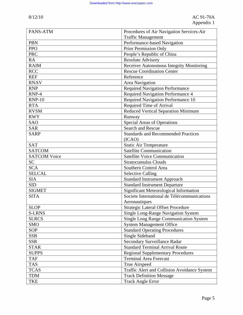
8/12/10 AC 91-70A Appendix 1
PANS-ATM Procedures of Air Navigation Services-Air Traffic Management
PBN Performance-based Navigation PPO Prior Permission Only PRC People’s Republic of China RA Resolute Advisory RAIM Receiver Autonomous Integrity Monitoring RCC Rescue Coordination Center REF Reference RNAV Area Navigation RNP Required Navigation Performance RNP-4 Required Navigation Performance 4 RNP-10 Required Navigation Performance 10 RTA Required Time of Arrival RVSM Reduced Vertical Separation Minimum RWY Runway SAO Special Areas of Operations SAR Search and Rescue SARP Standards and Recommended Practices
(ICAO) SAT Static Air Temperature SATCOM Satellite Communication SATCOM Voice Satellite Voice Communication SC Stratocumulus Clouds SCA Southern Control Area SELCAL Selective Calling SIA Standard Instrument Approach SID Standard Instrument Departure SIGMET Significant Meteorological Information SITA Societe International de Télécommunications
Aeronautiques SLOP Strategic Lateral Offset Procedure S-LRNS Single Long-Range Navigation System SLRCS Single Long Range Communication System SMO System Management Office SOP Standard Operating Procedures SSB Single Sideband SSR Secondary Surveillance Radar STAR Standard Terminal Arrival Route SUPPS Regional Supplementary Procedures TAF Terminal Area Forecast TAS True Airspeed TCAS Traffic Alert and Collision Avoidance System TDM Track Definition Message TKE Track Angle Error
Page 5
Downloaded from http://www.everyspec.com

AC 91-70A 8/12/10 Appendix 1
Page 6
TMI Track Message Identifier TOD Top of Descent TSA Transportation Security Administration TSO Technical Standard Order UHF Ultrahigh Frequency UPR User Preferred Routes USB Upper Sideband USNOF United States NOTAM Office UTA Upper Control Area UTC Universal Time Coordinated VDP Visual Descent Point VFR Visual Flight Rules VHF Very High Frequency VLF Very Low Frequency VMC Visual Meteorological Conditions VOLMET Meteorological Information For Aircraft In
Flight VOR/DME VHF Omnidirectional Range/Distance
Measuring Equipment WAC World Aeronautical Charts WAH When Able Higher WATRS West Atlantic Route System XTK Cross-Track Error
Downloaded from http://www.everyspec.com

8/12/10 AC 91-70A Appendix 2
APPENDIX 2. SAMPLE OCEANIC CHECKLIST
1. SAMPLE OCEANIC CHECKLIST
NOTE: International Civil Aviation Organization (ICAO) North Atlantic Working Groups composed of industry, air traffic control (ATC) and state regulators have created this checklist. For reference only, it does not replace an operator’s oceanic checklist. We encourage operators without an oceanic checklist to use this sample and tailor it to their specific needs and approvals. This checklist focuses on an orderly flow and ways to reduce oceanic errors. Operators should also review the attached expanded checklist. Use the Oceanic Errors Safety Bulletin (OESB) with this checklist. You can find the OESB at www.nat-pco.org.
FLIGHT PLANNING • Plotting Chart – plot route
from coast out to coast in • Equal Time Points (ETP) –
plot • Track message (current copy
available for all crossings) • Note nearest tracks on plotting
chart • Review possible navigation
aids for accuracy check prior to coast out
PREFLIGHT • Master Clock for all estimated
times of arrival (ETA)/actual times of arrival (ATA)
• Maintenance Log – check for any navigation/ communication/surveillance or Reduced Vertical Separation Minimum (RVSM) issues
• RVSM • Altimeter checks (tolerance) • Wind shear or turbulence
forecast • Computer Flight Plan (CFP)
vs. ICAO Flight Plan (check routing, fuel load, times, groundspeeds)
• Dual Long-Range NAV System (LRNS) for remote oceanic operations
• High frequency (HF) check (including Selective Call (SELCAL))
• Confirm Present Position coordinates (best source)
• Master CFP (symbols: O, V, \, X)
• LRNS programming • Check navigation database
currency and software version • Independent verification • Check expanded coordinates
of waypoints • Track and distance check
(+ 2o and + 2 nautical miles
(NM)) • Upload winds, if applicable. • Groundspeed check
TAXI AND PRIOR TO TAKE-OFF • Groundspeed check • Present Position check
CLIMB OUT • Transition altitude – set
altimeters to 29.92 in (1013.2 hPa)
Page 1
Downloaded from http://www.everyspec.com

AC 91-70A 8/12/10 Appendix 2
• Manually compute ETAs above flight level (FL) 180
PRIOR TO OCEANIC ENTRY • Gross error accuracy check –
record results • HF check, if not done during
preflight • Log on to Controller-Pilot
Data Link Communications (CPDLC) or Automatic Dependent Surveillance (ADS) 15 to 45 minutes prior, if equipped
• Obtain oceanic clearance from appropriate clearance delivery
• Confirm and maintain correct FL at oceanic boundary
• Confirm FL, Mach and Route for crossing
• Advise air traffic control (ATC) When Able Higher (WAH)
• Ensure aircraft performance capabilities for maintaining assigned altitude/assigned Mach
• Re-clearance – update LRNS, CFP and plotting chart
• Check track and distance for new route
• Altimeter checks – record readings
• Compass heading check – record
AFTER OCEANIC ENTRY • Squawk 2000 – 30 minutes
after entry, if applicable • Maintain assigned Mach, if
applicable • Very high frequency (VHF)
radios-set to inter-plane and guard frequency
• Strategic Lateral Offset Procedure (SLOP) – standard operating procedure (SOP)
• Hourly altimeter checks
APPROACHING WAYPOINTS • Confirm next
latitude/longitude
OVERHEAD WAYPOINTS • Confirm aircraft transitions to
next waypoint • Check track and distance
against Master CFP • Confirm time to next waypoint • Note: 3-minute or more
change requires ATC notification
• Position report – fuel
10-MINUTE PLOT AFTER WAYPOINT • Record time and
latitude/longitude on plotting chart – non steering LRNS
MIDPOINT • Midway between waypoints
compare winds from CFP, LRNS and upper millibar wind charts
• Confirm time to next waypoint
COAST IN • Compare ground based
Navigational Aid (NAVAID) to LRNS
• Remove Strategic Lateral Offset
• Confirm routing after oceanic exit
DESCENT • Transition level – set
altimeters to QNH
Page 2
Downloaded from http://www.everyspec.com

8/12/10 AC 91-70A Appendix 2
Page 3
DESTINATION/BLOCK IN • Navigation Accuracy Check • RVSM write-ups
OTHER ISSUES • Contingencies
• Published Weather Deviation Procedure
• 15 nautical mile (NM) offset (formerly 30 NM in the North Atlantic (NAT), 25 NM in the Pacific)
• Lost Communication/Navigation Procedures
• Extended Operations (ETOPS) • Weather –
Destination/Alternate(s) Airport(s)
• Data Link Contingency Procedures
• Dead Reckoning (DR) • Global positioning system
(GPS) – receiver autonomous integrity monitoring (RAIM)/fault detection and exclusion (FDE) Requirements
Downloaded from http://www.everyspec.com

AC 91-70A 8/12/10 Appendix 2
2. EXPANDED OCEANIC CHECKLIST.
a. Flight Planning.
(1) Plotting Chart. Use a plotting chart of appropriate scale for all remote oceanic operations. This includes using a plotting chart for published oceanic routes and tracks. ICAO groups who review oceanic errors have determined that the routine use of a plotting chart is an excellent aid to reduce lateral errors. A plotting chart can also serve as a critical aid in case of partial or total navigation failure. Note that the pilot should read from the plotting chart back to the Master CFP when verifying data. To read from the Master CFP to the plotting chart is a human factor’s issue that has lead to errors based on seeing what we expect to see.
(2) ETP. Compute ETPs for contingencies such as medical divert, engine loss or rapid depressurization. You should also consider a simultaneous engine loss and rapid depressurization. It is advisable to note the ETPs on the plotting chart. Crewmembers should review with each other the appropriate diversion airport(s) when crossing ETPs. Pilot procedures should also include a manual method for computing ETPs.
(3) Track Message. Crews must have a current track message even if filed for a random route. Reviewing the date, effective Zulu time and Track Message Identifier (TMI) ensures having a current track message onboard. The TMI links to the Julian Date. Operators must also ensure that their flight planning and operational control process notify crewmembers in a timely manner of any amendments to the daily track message. Plotting tracks near the assigned route can help situational awareness (SA) in case the crew needs to execute a contingency.
(4) Review NAVAIDs for Accuracy Check Prior to Coast Out. It is good practice to discuss in advance a primary and secondary ground-based NAVAID that you will use to verify the accuracy of the LRNS. This planning may help to identify intended NAVAIDs that are limited or NOTAM’d unusable and is helpful when departing airports close to oceanic airspace. Examples include Shannon (EINN), Lisbon (LRRT), Los Angeles (KLAX), etc.
b. Preflight.
(1) Master Clock. It is a requirement to have a master clock onboard synchronized to universal coordinated time (UTC) or GPS. Use this time source, which is typically the flight management system (FMS), for all ETAs and ATAs. The use of multiple time sources on the aircraft has lead to inconsistencies in reporting times to ATC and resulted in a loss of longitudinal separation.
(2) Maintenance Log. Before entering a special area of operation, crews should focus on any write-ups that affect communication, navigation, surveillance or RVSM requirements. Any discrepancies noted in the maintenance log or during the walk-around may require delays or rerouting.
(3) RVSM. Required equipment includes two primary independent altimetry sources, one altitude alert system, and one automatic altitude control system. In most cases, a functioning transponder that you can link to the primary altimetry source is also required. Crews should note any issues that can affect accurate altimetry.
Page 4
Downloaded from http://www.everyspec.com

8/12/10 AC 91-70A Appendix 2
(4) Altimeter Checks. Before taxi, crews should set their altimeters to the airport QNH. Both primary altimeters must agree within + 75 feet of field elevation. The two primary altimeters must also agree within the limits noted in the aircraft operating manual.
(5) Wind Shear or Turbulence Forecast. Review the Master CFP with projected wind shear or the turbulence forecast documents for flights in RVSM airspace. Forecast moderate or greater turbulence could lead to RVSM suspension. We caution operators against flight planning through areas of forecast moderate or greater turbulence.
(6) CFP. Carefully check the document designated as the Master CFP for date, type aircraft, fuel load, and performance requirements. You should also do cross-checks for routing and forecast groundspeeds. Carefully check the CFP against the ICAO filed flight plan to ensure the routing is in agreement with both documents. Compare the en route time on the CFP against the distance to destination for a reasonable groundspeed. You should also compare the en route time against the total distance for a reasonable fuel load.
(7) Dual LRNS. Remote oceanic operations require two operational LRNSs. A single FMS does not have the authorization for remote oceanic operations.
(8) High Frequency (HF) Check. Conduct an HF check on the primary and secondary HF radios in areas where dual HF radios are required. If possible, do the HF checks on the ground or before entering oceanic airspace. You should also accomplish a Selective Call (SELCAL) check.
(9) Confirm Present Position Coordinates. Both pilots should independently verify the present position coordinates using either published ramp coordinates or determine position from the airfield diagram. They should not rely solely on the present position when the LRNS was shut down from the previous flight. You should also use a master source such as an en route chart to confirm accuracy of coordinates at the oceanic boundaries.
(10) Master CFP Symbols. We encourage operators to use consistent symbology on the Master CFP. For example, a circled number (O) means the second crewmember has independently verified the coordinates entered or cross-checked by the first crewmember. A checkmark may indicate confirmation of the track and distances. A diagonal line (\) may indicate that the crew has confirmed the coordinates of the approaching and next waypoint. An X-symbol (X) may indicate having flown overhead the waypoint.
c. LRNS Programming.
(1) Check Currency and Software Version. It is important to check the effective date of the database. Crews should note if the project the database to expire during their trip. We discourage crews from flying with expired databases. Minimum equipment lists (MEL) may allow relief to fly with an expired database but require the crews to manually cross-check all data. You should also confirm the software version of the database in case there was a change.
(2) Independent Verification. It is critical that one crewmember enters waypoint coordinates and another crewmember independently checks them. Note that the pilot should read from the FMS screen back to the Master CFP when verifying data. To read from the Master CFP
Page 5
Downloaded from http://www.everyspec.com

AC 91-70A 8/12/10 Appendix 2
to the FMS is a human factor’s issue that has lead to errors based on seeing what we expect to see.
(3) Check Expanded Coordinates of Waypoints. Most FMSs allow entering abbreviated oceanic coordinates. There have been cases when there was an error in the expended waypoint coordinate, but crews only checked the abbreviated coordinate. Verifying only the abbreviated coordinate could lead to a lateral error. Flightcrews should conduct a magnetic course and distance check between waypoints to further verify waypoint coordinates.
(4) Track and Distance Check. To minimize oceanic errors, it is important to conduct a magnetic course and distance check from oceanic entry to oceanic exit. Operators should establish a tolerance such as + 2° and + 2 NM. The course and distance check comparing the Master CFP against the LRNS are critical in detecting errors you may not have noticed by simply checking coordinates. A difference of more than 2° between waypoints may be due to a difference of the magnetic variation in the database versus the variation used in the Master CFP. Recheck and verify any difference outside the + 2° or + 2 NM.
(5) Upload Winds. Some LRNS units allow the crew to upload projected winds. This procedure allows more accurate reporting of ETAs.
(6) Groundspeed Check. Note the groundspeed before taxiing the aircraft. Crews should expect the groundspeed to read zero (0) knots. This procedure is a good practice to detect an error that may be developing in the LRNS.
d. Taxi and Prior to Take-off.
(1) Groundspeed Check. During taxi to the active runway, pilots should check the groundspeed to see if it is reasonable.
(2) Present Position Check. Conduct this present position check after leaving the gate. Check for gross difference between this present position and the gate coordinates. This check will alert the crew to possible error in the LRNS database that they can investigate/correct prior to take-off.
e. Climb Out.
(1) Transition Altitude. Crews should brief the transition altitude based on information from the approach plate or from the automated terminal information service (ATIS). After climbing through the transition altitude, the altimeters should be reset to 29.92 inches or 1013.2 hectopascals (hPa).
(2) Manually Compute ETAs. After climbing above the sterile altitude and time permitting crews should manually compute ETAs from departure to destination. Note these on the Master CFP. This is an excellent cross-check against ETAs computed by the LRNS.
f. Prior to Oceanic Entry.
Page 6
Downloaded from http://www.everyspec.com

8/12/10 AC 91-70A Appendix 2
(1) Gross Error Accuracy Check. Before oceanic entry, check the accuracy of the LRNS against a ground-based NAVAID. Record the results of the accuracy check with the time and position. A large difference between the ground-based NAVAID and the LRNS may require immediate corrective action. Operators should establish a gross error check tolerance based on the type of LRNS. It is not advisable for crews to attempt to correct an error by doing an air alignment or by manually updating the LRNS since this has often contributed to a gross navigation error (GNE).
(2) HF Checks. If the crew was unable to accomplish the HF and SELCAL checks on the ground, they must accomplish these checks before oceanic entry.
(3) Log on to CPDLC or Automatic Dependent Surveillance (ADS). Operators approved to use CPDLC or ADS should log on to the appropriate FIR 15 to 45 minutes prior to the boundary.
(4) Obtain Oceanic Clearance. Both pilots must obtain oceanic clearance from the appropriate clearance delivery (OCD). (Clearance via voice should be at least 40 minutes prior to oceanic entry and via data link should be 30 to 90 minutes prior to oceanic entry). It is important that both pilots confirm and enter the ocean at the altitude assigned in the oceanic clearance (this may be different than the domestic cleared FL). An oceanic clearance typically includes a route, FL and assigned Mach. Crews should include their requested FL in their initial clearance request. Some oceanic centers require pilots to advise them at the time of their oceanic clearance When Able Higher (WAH). Crews should be confident that they are able to maintain requested FLs based on aircraft performance capabilities.
(5) Re-Clearance. A re-clearance (that is different from the oceanic route requested with the filed flight plan) is the number one scenario which leads to a GNE. Crews must be particularly cautious when receiving a re-clearance. Both pilots should receive and confirm the new routing and conduct independent cross-checks after updating the LRNS, Master CFP, and plotting chart. It is critical that crews check the magnetic course and distance between the new waypoints as noted in PREFLIGHT under the paragraph “LRNS Programming.”
(6) Altimeter Checks. Crews are required to check the two primary altimeters which must be within 200 feet of each other. Conduct this check while at level flight. You should also note the stand-by altimeter. Record the altimeter readings with the time.
(7) Compass Heading Check. We recommend conducting a compass heading check and record the results. This check is particularly helpful with inertial systems. The check can also aid in determining the most accurate compass if a problem develops over water.
g. After Oceanic Entry.
(1) Squawk 2000. Thirty minutes after oceanic entry, crews should Squawk 2000, if applicable. There may be regional differences such as Squawking 2100 in Bermuda’s airspace or maintaining last assigned Squawk in the West Atlantic Route System (WATRS). Crews transiting Reykjavik’s airspace must maintain last assigned Squawk.
Page 7
Downloaded from http://www.everyspec.com

AC 91-70A 8/12/10 Appendix 2
(2) Maintain Assigned Mach. Some oceanic clearances include a specific Mach. There is no tolerance for this assigned Mach. The increased emphasis on longitudinal separation requires crew vigilance in a separation based on assigned Mach. The requirement is to maintain the true Mach assigned by ATC. In most cases, the indicated Mach is the true Mach. Some aircraft, however, require a correction factor.
(3) VHF Radios. After going beyond the range of the assigned VHF frequency, crews should set their radios to inter-plane (123.45) and guard frequency (121.5).
(4) SLOP. The SLOP should be SOP for all oceanic crossings. This procedure reduces the risk from highly accurate navigation systems or operational errors involving the ATC clearance. SLOP also replaced the contingency procedure developed for aircraft encountering wake turbulence. Depending upon winds aloft, coordination between aircraft to avoid wake turbulence may be necessary. This procedure of flying centerline (CL), 1 NM or 2 NM right of CL, greatly reduces the risk to the airspace by the nature of the randomness. Aircraft that do not have an automatic offset capability (that can be programmed in the LRNS) should fly the CL only. SLOP is not for operators to use only in contingency situations.
(5) Hourly Altimeter Checks. Crews are to observe the primary and stand-by altimeters each hour. We recommend that you record these hourly checks with the readings and times. This documentation can aid crews in determining the most accurate altimeter if an altimetry problem develops.
h. Approaching Waypoints and Confirming Next Latitude/Longitude. Within a few minutes of crossing an oceanic waypoint, crews should cross-check the coordinates of that waypoint and the next waypoint. This check should be done by comparing the coordinates against the Master CFP based on the currently effective ATC clearance.
i. Overhead Waypoints.
(1) Confirm Aircraft Transitions to Next Waypoint. When overhead an oceanic waypoint, crews should ensure that the aircraft transitions to the next leg. Noting the magnetic heading and distance to the next waypoint compared against the Master CFP confirms this.
(2) Confirm Time to Next Waypoint. Crews must be vigilant in passing an accurate ETA to ATC for the next waypoint. A change of 3 minutes or more requires that ATC receives notification in a timely manner. There is substantial emphasis on reducing longitudinal separation and this timely update must be a priority for the crews.
(3) Position Report. After passing over the oceanic waypoint, crews that give a position report to ATC must use the standard format. Flights designated as meteorology information (MET) reporting flights or flights on random routes should be including in the position report additional items such as winds and temperatures. Crews should also note and record their field status at each oceanic waypoint. This is especially important if the cleared route and FL differ significantly from the filed flight plan.
j. Ten-Minute Plot. Approximately 10 minutes after passing an oceanic waypoint, crews should plot the latitude, longitude and time on the plotting chart. It is advisable to plot the
Page 8
Downloaded from http://www.everyspec.com

8/12/10 AC 91-70A Appendix 2
Page 9
non-steering LRNS. A 10-minute plot can alert the crew to any lateral deviation from their ATC clearance prior to it becoming a GNE. A good cross-check for the position of the 10-minute plot is that it is approximately 2° of longitude past the oceanic waypoint.
k. Midpoint.
(1) Midway Between Waypoints. It is good practice to cross-check winds midway between oceanic waypoints by comparing the Master CFP, LRNS and upper millibar wind chart. As noted before, this information will be in a position report if the flight is either a MET reporting flight or is a flight on a random route. This cross-check will also aid crews in case there is a need for a contingency such as DR.
(2) Confirm Time. We recommend that during a wind check the crews also confirm the ETA to the next waypoint noting the 2 minute tolerance.
l. Coast In.
(1) Compare Ground-Based NAVAID to LRNS. When departing oceanic airspace and acquiring ground-based NAVAIDs, crews should note the accuracy of the LRNS by comparing it to those NAVAIDs. Note any discrepancy in the maintenance log.
(2) Remove Strategic Lateral Offset. Crews using a lateral offset of 1 NM or 2 NM right of CL at oceanic entry need a procedure to remove this lateral offset at coast in prior to exiting oceanic airspace. It is advisable to include this as a checklist item.
(3) Confirm Routing after Oceanic Exit. Before entering the domestic route structure, crews must confirm their routing to include aircraft speed.
m. Descent and Transition Level. During the approach briefing, crews should note the transition level on the approach plate or verified by automated terminal information service (ATIS). Crews must be diligent when descending through the transition level to reset the altimeters to QNH. This is particularly important when encountering instrument flight rules (IFR), night or high terrain situations. Clarify any confusion between a QNH set with inches of Mercury or hPa.
n. Destination/Block In.
(1) Navigation Accuracy Check. When arriving at the destination gate, crews should note any drift or circular error in the LRNS. A GPS primary means system normally should not exceed 0.27 NM for the flight. Some inertial systems may drift as much as 2 NM per hour. Because the present generation of LRNSs is highly accurate, operators should establish a drift tolerance which, if exceeded, would require a write-up in the maintenance log. Required Navigation Performance (RNP) requirements demand close monitoring of drift.
(2) RVSM Write-Ups. Note problems noted in the altimetry system, altitude alert, or altitude hold in the maintenance log. Closely monitor the RVSM airspace for any height deviations. Do not flight plan an aircraft not meeting the strict RVSM standards into RVSM airspace without corrective action.
Downloaded from http://www.everyspec.com


![Back Spread right Cover - trustedpartner.azureedge.net · Front Spread left Front Spread right FOLDRite™ Template Master: AC-1 Accordion Fold [Side B]](https://static.fdocuments.us/doc/165x107/5b3db7557f8b9a5e1f8e3050/back-spread-right-cover-front-spread-left-front-spread-right-foldrite-template.jpg)