AC LINE FILTER Quarter-brick Temperature Variation 5 RTCA/DO-160G section 5.3.1 Temperature Cycling...
8
ACF-U-115-3PH-QG-C-G Avionics AC Line Filter 3-Phase 85-140 Vrms L-N 3 Arms 45-800 Hz ACF-U-115-3PH-QG-x AC LINE FILTER Quarter-brick ACF-U-115-3PH-QG-x # 005-0007196 Rev. 1 www.synqor.com 1-888-567-9596 3/28/2019 Page 1 In-Line Manufacturing Process • AS9100 and ISO 9001 certified facility • Full component traceability Avionic AC Line Filter 85 to 140 Vrms 3 Arms 1 kW @ 115 Vrms 700mΩ >40dB @ 200 kHz Input Voltage Output Current Output Power Max Series Attenuation Resistance Full Power Operation: -40ºC to +100ºC The AeroQor AC Line EMI Filter brings SynQor’s field proven technology and manufacturing expertise to the Avionics COTS Component marketplace. SynQor’s innovative packaging approach ensures survivability in the most hostile environments. Compatible with the industry-standard format, these filters have high differential-mode and common-mode attenuation and low series resistance. They follow conservative component derating guidelines and they are designed and manufactured to the highest standards. Designed and manufactured in the USA Operational Features • -40°C to +100°C Operation • 3 Arms output current • Very low series resistance • High Differential & Common-mode Attenuation • Meets common EMC standards in properly designed system with SynQor APFIC modules. Specification Compliance Pending • RTCA-D0 160 • Airbus ADB0100.1.8 • Boeing 787B3-0147 • Boeing D6-36440 • Boeing D6-44588 • CE marked Contents • Industry standard Quarter-brick size • Size: 1.54” x 2.39” x 0.50” (39.01 x 60.6 x 12.7 mm) • Weight: 2.9 oz (82 g) Mechanical Features Page No. Technical Diagrams ................................ 2 Technical Specification ............................. 3 Standards & Qualification ........................... 5 Encased Mechanical ............................... 6 Ordering Information .............................. 8
Transcript of AC LINE FILTER Quarter-brick Temperature Variation 5 RTCA/DO-160G section 5.3.1 Temperature Cycling...
ACF-U-115-3PH-QG-C-G
Avionics AC Line Filter
3-Phase 85-140 VrmsL-N
3 Arms 45-800 Hz
ACF-U-115-3PH-QG-xAC LINE FILTERQuarter-brick
ACF-U-115-3PH-QG-x # 005-0007196 Rev. 1 www.synqor.com 1-888-567-9596 3/28/2019 Page 1
In-Line Manufacturing Process
• AS9100 and ISO 9001 certified facility• Full component traceability
Avionic AC Line Filter 85 to 140 Vrms 3 Arms 1 kW @ 115 Vrms 700mΩ >40dB @ 200 kHz
Input Voltage Output Current Output Power Max Series Attenuation
Resistance
Full Power Operation: -40ºC to +100ºC
The AeroQor AC Line EMI Filter brings SynQor’s field proven technology and manufacturing expertise to the Avionics COTS Component marketplace. SynQor’s innovative packaging approach ensures survivability in the most hostile environments. Compatible with the industry-standard format, these filters have high differential-mode and common-mode attenuation and low series resistance. They follow conservative component derating guidelines and they are designed and manufactured to the highest standards.
Designed and manufactured in the USA
Operational Features
• -40°C to +100°C Operation • 3 Arms output current• Very low series resistance• High Differential & Common-mode Attenuation• Meets common EMC standards in properly designed system with SynQor APFIC modules.
Specification Compliance
Pending• RTCA-D0 160• Airbus ADB0100.1.8• Boeing 787B3-0147• Boeing D6-36440• Boeing D6-44588• CE marked
Contents
• Industry standard Quarter-brick size• Size: 1.54” x 2.39” x 0.50” (39.01 x 60.6 x 12.7 mm)• Weight: 2.9 oz (82 g)
Mechanical Features Page No.Technical Diagrams. . . . . . . . . . . . . . . . . . . . . . . . . . . . . . . . 2Technical Specification . . . . . . . . . . . . . . . . . . . . . . . . . . . . . 3Standards & Qualification . . . . . . . . . . . . . . . . . . . . . . . . . . . 5Encased Mechanical . . . . . . . . . . . . . . . . . . . . . . . . . . . . . . . 6Ordering Information . . . . . . . . . . . . . . . . . . . . . . . . . . . . . . 8
ACF-U-115-3PH-QG-xInput: 85 to 140 Vrms
Output:45-800 HzPower: 1.0 kW @ 115 Vrms
ACF-U-115-3PH-QG-x # 005-0007196 Rev. 1 www.synqor.com 1-888-567-9596 3/28/2019 Page 2
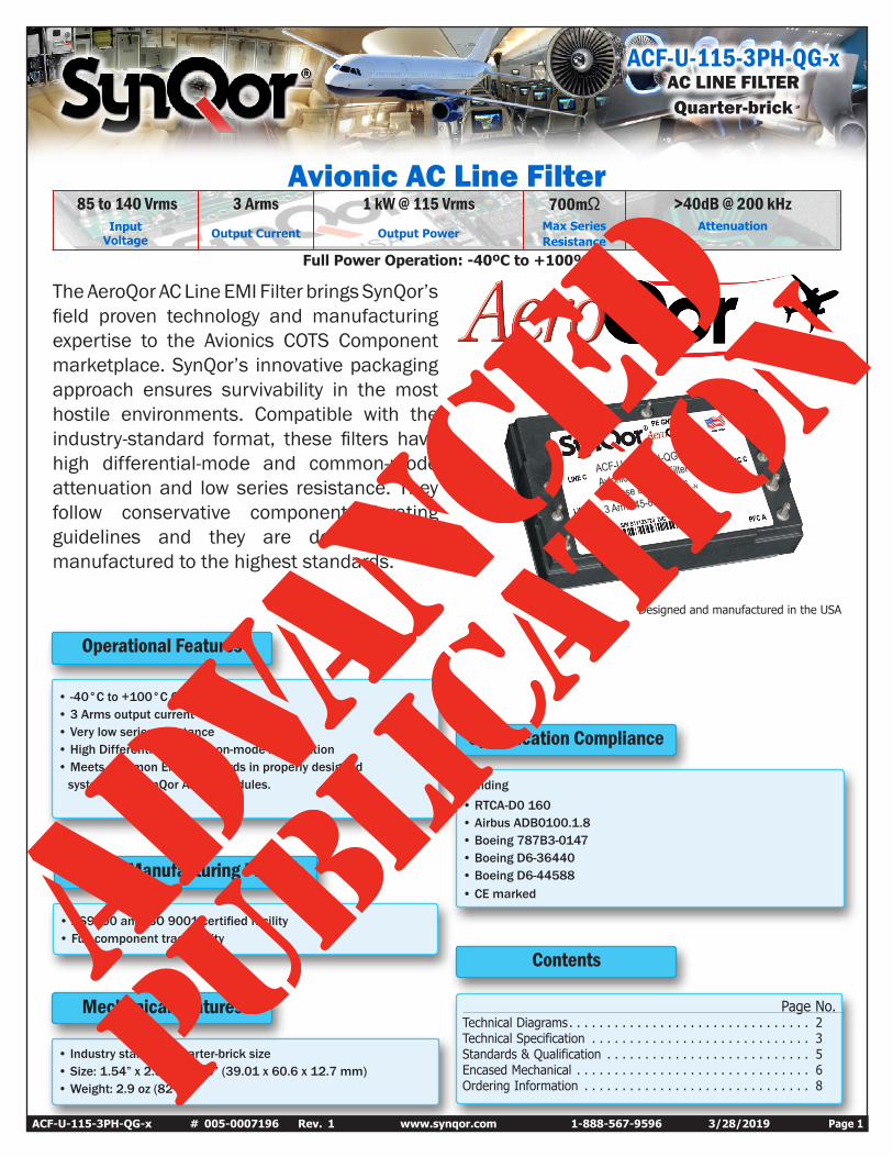
Circuit & Typical Connection Diagram
FUSE1
FUSE2
FUSE3
MOV1
MOV3MOV2
ACF-U-115-3PH-QGSynQor 3-Phase AC Line Filter
SynQor Isolated3-Phase
PFC Module
TVS1
TVS2 TVS3
BaseplateBASIC ISOLATION
BASIC ISOLATION
-VOUT
+VOUT
LINE B
LINE A
LINE C
LINE B
LINE A
LINE C
PE GND
PFC B
PFC A
PFC C
Suggested Parts:
MOV 1-3: 300VAC, 60J; (EPCOS S10K300E2)TVS 1-3: 430 Vpk, 20 J; (Littelfuse AK3-430C or Bourns PTVS-430C-TH)Fuse 1-3: 250 Vrms, 10 A; (Littelfuse 0216010.XEP)
ACF-U-115-3PH-QG-xInput: 85 to 140 Vrms
Output:45-800 HzPower: 1.0 kW @ 115 Vrms
ACF-U-115-3PH-QG-x # 005-0007196 Rev. 1 www.synqor.com 1-888-567-9596 3/28/2019 Page 3
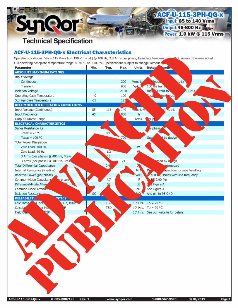
ACF-U-115-3PH-QG-x Electrical CharacteristicsOperating conditions: Vin = 115 Vrms L-N (199 Vrms L-L) @ 400 Hz; 2.3 Arms per phase; baseplate temperature = 25°C unless otherwise noted.Full operating baseplate temperature range is -40 °C to +100 °C. Specifications subject to change without notice. Parameter Min. Typ. Max. Units Notes & Conditions ABSOLUTE MAXIMUM RATINGS Input Voltage
Continuous 200 Vrms L-N Continuous (346 Vrms L-L)Transient 900 Vpk L-L 100 ms transient
Isolation Voltage 2150 Vdc Input/Output to baseplate/PE GND Operating Case Temperature -40 100 °C Baseplate temperature Storage Case Temperature -55 125 °C RECOMMENDED OPERATING CONDITIONS Input Voltage (Continuous) 85 115 140 Vrms L-N 147 to 242 Vrms L-L Input Frequency 45 800 Hz Output Current Range 3.0 Arms Per phase ELECTRICAL CHARACTERISTICS Series Resistance Rs Per phase
Tcase = 25 ºC 480 540 mΩ Tcase = 100 ºC 700 mΩ Guaranteed by design
Total Power DissipationZero Load, 400 Hz 2.0 WZero Load, 60 Hz 1.3 W3 Arms (per phase) @ 400 Hz, Tcase = 25 ºC 15 W3 Arms (per phase) @ 400 Hz, Tcase = 100 ºC 21 W Guaranteed by design
Total Differential Capacitance 0.40 µF Per Phase, Y connected Internal Resistance (line-line) 1.5 MΩ Discharges capacitors for safe handling Reactive Power (per phase) 15 VAR At 400 Hz; scales with line frequency Common-Mode Capacitance (per phase) 4.7 nF To PE GND Pin Differential-Mode Attenuation, 200 kHz 55 dB See Figure A Common-Mode Attenuation, 200 kHz 40 dB See Figure A Isolation Resistance 100 MΩ Any pin to PE GND RELIABILITY CHARACTERISTICS Calculated MTBF per Telcordia SR-332, Issue 2 TBD 106 Hrs. Tb = 70 °C Calculated MTBF per MIL-HDBK-217F TBD 106 Hrs. Tb = 70 °C Field Demonstrated MTBF 106 Hrs. See our website for details
Technical Specification
ACF-U-115-3PH-QG-xInput: 85 to 140 Vrms
Output:45-800 HzPower: 1.0 kW @ 115 Vrms
ACF-U-115-3PH-QG-x # 005-0007196 Rev. 1 www.synqor.com 1-888-567-9596 3/28/2019 Page 4
-80
-60
-40
-20
0
20
2 20 200 2,000
Atte
nuat
ion
(dB)
Frequency (kHz)
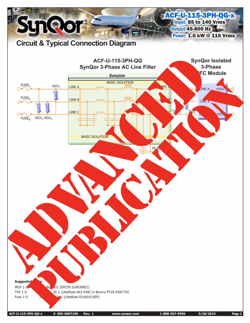
Differential-Mode
Common-Mode
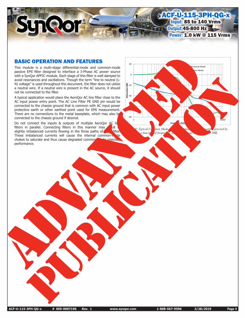
BASIC OPERATION AND FEATURESThis module is a multi-stage differential-mode and common-mode passive EMI filter designed to interface a 3-Phase AC power source with a SynQor APFIC module. Each stage of this filter is well damped to avoid resonances and oscillations. Though the term “line to neutral (L-N) voltage” is used throughout this document, the filter does not utilize a neutral wire. If a neutral wire is present in the AC source, it should not be connected to the filter.A typical application would place the AeroQor AC line filter close to the AC input power entry point. The AC Line Filter PE GND pin would be connected to the chassis ground that is common with AC input power protective earth or other earthed point used for EMI measurement. There are no connections to the metal baseplate, which may also be connected to the chassis ground if desired.Do not connect the inputs & outputs of multiple AeroQor AC line filters in parallel. Connecting filters in this manner may result in slightly imbalanced currents flowing in the three paths of each filter. These imbalanced currents will cause the internal common-mode chokes to saturate and thus cause degraded common-mode rejection performance.
Figure 1: Typical Common Mode and Differential Mode Attenuation provied by the filter as a function of frequency. Source and load resistance are 50Ω.
ACF-U-115-3PH-QG-xInput: 85 to 140 Vrms
Output:45-800 HzPower: 1.0 kW @ 115 Vrms
ACF-U-115-3PH-QG-x # 005-0007196 Rev. 1 www.synqor.com 1-888-567-9596 3/28/2019 Page 5
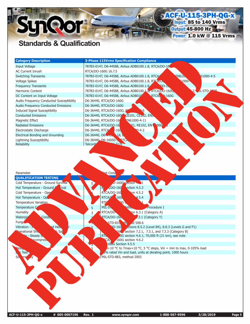
Standards & Qualification
Parameter # Units Test Conditions QUALIFICATION TESTING Cold Temperature - Ground Survival 5 RTCA/DO-160G section 4.5.1 Hot Temperature - Ground Survival 5 RTCA/DO-160G section 4.5.3 Cold Temperature - Operating 5 RTCA/DO-160G section 4.5.2 Hot Temperature - Operating 5 RTCA/DO-160G section 4.5.4 Temperature Variation 5 RTCA/DO-160G section 5.3.1 Temperature Cycling 5 MIL-STD-810G Method 503.5 – Procedure I Humidity 3 RTCA/DO-160G section 6.3.1 (Category A) Waterproofness - Condensing 3 RTCA/DO-160 section 10.3.1 (Category Y) Fungus Resistance 1 MIL-STD-810G Method 508.6 Vibration - Fixed Wing and Helicopter 5 RTCA/DO-160G sections 8.5.2 (Level B4), 8.8.3 (Levels G and F1) Operational Shock and Crash Safety 5 RTCA/DO-160G section 7.2.1, 7.3.1, and 7.3.3 (Category B) Altitude - Steady State 5 RTCA/DO-160G section 4.6.1; 70,000 ft (21 km), see note Altitude - Decompression 5 RTCA/DO-160G section 4.6.2 Loss of Cooling 5 DO-160G Section 4.5.5 Design Marginality 5 Tmin-10 °C to Tmax+10 °C, 5 °C steps, Vin = min to max, 0-105% load Life Test 32 95% rated Vin and load, units at derating point, 1000 hours Solderability 7 pins MIL-STD-883, method 2003
Category Description 3-Phase 115Vrms Specification Compliance
Input Voltage 787B3-0147, D6-44588, Airbus ADB0100.1.8, RTCA/DO-160G AC Current Inrush RTCA/DO-160G 16.7.5 Switching Transients 787B3-0147, D6-44588, Airbus ADB0100.1.8, RTCA/DO-160G, EN61000-4-4, EN61000-4-5 Voltage Spikes 787B3-0147, D6-44588, Airbus ADB0100.1.8, RTCA/DO-160G, EN61000-4-6 Frequency Transients 787B3-0147, D6-44588, Airbus ADB0100.1.8, RTCA/DO-160G Harmonic Content 787B3-0147, D6-44588, Airbus ADB0100.1.8, RTCA/DO-160G, EN61000-3-2, MIL-STD-1399 DC Content on Input Voltage 787B3-0147, D6-44588, Airbus ADB0100.1.8, RTCA/DO-160G Audio Frequency Conducted Susceptibility D6-36440, RTCA/DO-160G Audio Frequency Conducted Emissions D6-36440, RTCA/DO-160G Induced Signal Susceptibility D6-36440, RTCA/DO-160G, EN61000-4-6 Conducted Emissions D6-36440, RTCA/DO-160G, CE101, CE102, EN55011/22 Magnetic Effect D6-36440, RTCA/DO-160G, EN61000-4-11 Radiated Emissions D6-36440, RTCA/DO-160G, RE101, RE102, EN 61000-4-3 Electrostatic Discharge D6-36440, RTCA/DO-160G, EN61000-4-2 Electrical Bonding and Grounding D6-36440, D6-44588, UL 60950-1 Lightning Susceptibility D6-36440, D6-16050-5, RTCA/DO-160G Reliability Telcordia, MIL-HDBK-217F

ACF-U-115-3PH-QG-xInput: 85 to 140 Vrms
Output:45-800 HzPower: 1.0 kW @ 115 Vrms
ACF-U-115-3PH-QG-x # 005-0007196 Rev. 1 www.synqor.com 1-888-567-9596 3/28/2019 Page 6
Encased Mechanical
1.536 0.020[39.01 0.50]
1.030 [26.16] 0.09 [2.2]
0.06 [1.5]
Seating Plane Height0.500 0.02012.70 0.50[ ]
2.386 0.020[60.60 0.50]
1.860[47.24]
M3x0.5Insert
0.01 [0.3]
Pin Extension0.165[4.19]
1
0.300 [7.62]
0.600 [15.24]
0.300 [7.62]
0.600 [15.24]
1.225 [31.12]
2.000[50.80]
0.940[23.88]
1 2 3
4
567
NOTES1) Applied torque per M3 screw should not exceed 6in-lb. (0.7 Nm).
Screw is not to exceed 0.100” (2.54 mm) below the surface of the baseplate.2) Pins are are 0.040” (1.02mm) diameter, with 0.080”
(2.03mm) diameter standoff shoulders. 3) All Pins: Material - Copper Alloy
Finish: Matte Tin over Nickel plate4) Total weight: 2.9oz (82 g)5) All dimensions in inches (mm)
Tolerances: x.xx +/-0.02 in. (x.x +/-0.5mm) x.xxx +/-0.010 in. (x.xx +/-0.25mm)
PIN DESIGNATIONS
Pin Label Name Function
1 LINE A LINE A AC Line Input A2 LINE B LINE B AC Line Input B3 LINE C LINE C AC Line Input C4 PE GND PE GND Protective Earth5 PFC C PFC C Filter Output C6 PFC B PFC B Filter Output B7 PFC A PFC A Filter Output A
ACF-U-115-3PH-QG-xInput: 85 to 140 Vrms
Output:45-800 HzPower: 1.0 kW @ 115 Vrms
ACF-U-115-3PH-QG-x # 005-0007196 Rev. 1 www.synqor.com 1-888-567-9596 3/28/2019 Page 7
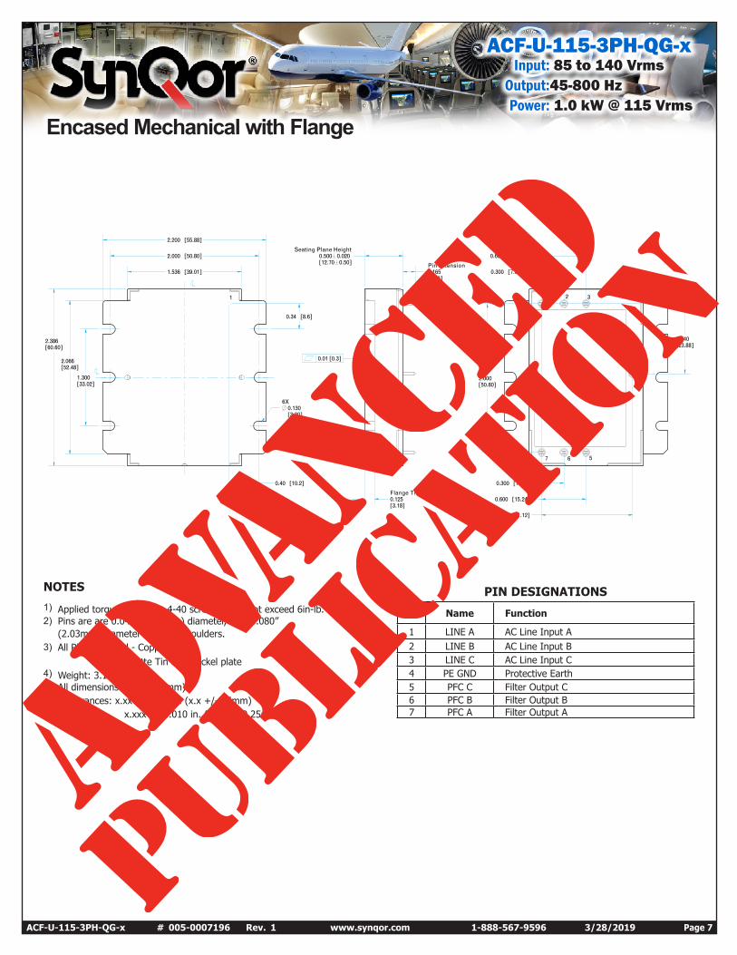
Encased Mechanical with Flange
Seating Plane Height0.500 0.02012.70 0.50[ ]
2.000 [50.80]
1.536 [39.01]
2.200 [55.88]
1.300[33.02]
2.066[52.48]
2.386[60.60]
0.34 [8.6]
0.01 [0.3]
0.300 [7.62]
0.600 [15.24]
Pin Extension0.165[4.19]
6X0.130[3.30]
2.000[50.80]
0.940[23.88]
0.300 [7.62]
0.600 [15.24]Flange Thickness0.125[3.18]
0.40 [10.2]
1.225 [31.12]
1 2 3
4
567
1
NOTES
1) Applied torque per M3 or 4-40 screw should not exceed 6in-lb. (0.7 Nm).2) Pins are are 0.040” (1.02mm) diameter, with 0.080”
(2.03mm) diameter standoff shoulders. 3) All Pins: Material - Copper Alloy
Finish: Matte Tin over Nickel plate4) Weight: 3.1 oz (88 g)5) All dimensions in inches (mm)
Tolerances: x.xx +/-0.02 in. (x.x +/-0.5mm) x.xxx +/-0.010 in. (x.xx +/-0.25mm)
PIN DESIGNATIONS
Pin Name Function
1 LINE A AC Line Input A2 LINE B AC Line Input B3 LINE C AC Line Input C4 PE GND Protective Earth5 PFC C Filter Output C6 PFC B Filter Output B7 PFC A Filter Output A

ACF-U-115-3PH-QG-xInput: 85 to 140 Vrms
Output:45-800 HzPower: 1.0 kW @ 115 Vrms
ACF-U-115-3PH-QG-x # 005-0007196 Rev. 1 www.synqor.com 1-888-567-9596 3/28/2019 Page 8
Part Numbering Scheme
Family Input Frequency Input Voltage Package Size Thermal Design RoHS
ACF U: 45 - 800 Hz 115-3PH: 115Vrms 3Ф QG: Quarter-Brick GigaC: Encased Threaded
G: RoHSV: Flanged
Example: ACF-U-115-3PH-QG-C-G
WARRANTYSynQor offers a two (2) year limited warranty. Complete warranty information is listed on our website or is available upon request from SynQor.
Contact SynQor for further information and to order: Phone: 978-849-0600 Toll Free: 888-567-9596 Fax: 978-849-0602 E-mail: [email protected] Web: www.synqor.com Address: 155 Swanson Road Boxborough, MA 01719 USA
RoHS Compliance: The EU led RoHS (Restriction of Hazardous Substances) Directive bans the use of Lead, Cadmium, Hexavalent Chromium, Mercury, Polybrominated Biphenyls (PBB), and Polybrominated Diphenyl Ether (PBDE) in Electrical and Electronic Equipment. This SynQor product is 6/6 RoHS compliant. For more information please refer to SynQor’s RoHS addendum available at our RoHS Compliance / Lead Free Initiative web page or e-mail us at [email protected].
Validation, Verification & Certification
Concept Design Design & Verification Proof of Design Proof of Manufacturing Manufacturing Integration
• Generate electrical specification
• Review performance requirements
• Design simulation• Schematic• Qualify new components• Breadboard• Prelim thermal analysis
• Full layout• DFM/DFT Review• Build engineering
prototypes• Debug circuit• Worst-case electrical
testing• Component stress
analysis• Stability analysis• Abnormal electrical
testing• Specification review• Preliminary datasheet
• Build units and electrically characterize
• Verify electrical performance
• Verify component stress analysis
• Statistical variations• Thermal analysis and
imaging• HALT testing• Complete datasheet
• Controlled Production Build
• ATE testing• Yield analysis• Validate and finalize
manufacturing processes and Tooling
• 1000 hour life test• Qualification testing
(humidity, vibration, DMT, PTC, thermal and mechanical shock, altitude and solderability)
• Processes transfer• Full documentation release
(SCD’s, BOM, processes, procedures, etc.)
• Release qualification reports• Release final datasheet• Transfer units to finished
goods
USA Manufacturing Facility: AS9100 & ISO 9001 CertifiedSynQor considers in-house manufacturing to be a core competency and strategic advantage. All SynQor products are manufactured in our manufactur-ing facility at our corporate headquarters in Boxborough, MA, USA, utilizing state-of–the art equipment and proprietary assembly techniques. By main-taining both AS9100 and ISO9001 certifications, SynQor is able to provide the same level of attention to detail in our manufacturing processes as we do in our products. We utilize proprietary in-house developed manufacturing data and document control systems that allow us to operate in a paperless manufacturing environment, providing both maximized manufacturing efficiency and flexibility. Ultimately, our manufacturing expertise remains in-house, allowing us to maintain complete control over the quality and traceability of our product down to the component level to meet the most stringent cus-tomer and industry requirements.
Design, Engineering & Manufacturing ProcessSynQor employs a stringent, ECO controlled, 5-stage product development process, starting with product concept design and ending with manufacturing integration. We believe that a solid design and DFM review process leads to efficient manufacturing, higher performance, and enhanced reliability. By designing for reliability, SynQor greatly reduces the chance of field defects and increases product integrity.
Ordering Information
PATENTS SynQor holds numerous U.S. patents, one or more of which apply to most of its power conversion products. Any that apply to the product(s) listed in this document are identified by markings on the product(s) or on internal components of the product(s) in accordance with U.S. patent laws. SynQor’s patents include the following:
6,545,890 6,594,159 6,894,468 6,896,526 6,927,987 7,050,309
7,085,146 7,119,524 7,765,687 7,787,261 8,149,597 8,644,027