ABSTRACT Title of dissertation: A COMPREHENSIVE REUSE ... · Title of dissertation: A COMPREHENSIVE...
186
1 ABSTRACT Title of dissertation: A COMPREHENSIVE REUSE MODEL FOR COTS SOFTWARE PRODUCTS Daniil Yakimovich, Doctor of Philosophy, 2001 Dissertation directed by Professor Victor R. Basili Department of Computer Science Use of commercial off-the-shelf (COTS) products in software development can improve a product’s quality and reduce development time. However, it also can require a considerable integration effort. Early estimation of this effort will help developers to choose the right COTS products and to decide whether to develop their own software instead of using COTS. In this work we propose a COTS reuse process to help software developers evaluate COTS products and integrate the selected COTS products into their systems. The process also includes an approach for designing the architecture for COTS-based software systems and overcoming other incompatibilities between COTS products and the system. The process is based on the comprehensive reuse model by Basili and Rombach, and a classification scheme for software component incompatibilities. To test the model, projects from a graduate software engineering class were used. These empirical data showed that the
Transcript of ABSTRACT Title of dissertation: A COMPREHENSIVE REUSE ... · Title of dissertation: A COMPREHENSIVE...

1
ABSTRACT
Title of dissertation: A COMPREHENSIVE REUSE MODEL FOR COTS
SOFTWARE PRODUCTS
Daniil Yakimovich, Doctor of Philosophy, 2001
Dissertation directed by Professor Victor R. Basili Department of Computer Science
Use of commercial off-the-shelf (COTS) products in software development
can improve a product’s quality and reduce development time. However, it also can
require a considerable integration effort. Early estimation of this effort will help
developers to choose the right COTS products and to decide whether to develop their
own software instead of using COTS. In this work we propose a COTS reuse process
to help software developers evaluate COTS products and integrate the selected COTS
products into their systems. The process also includes an approach for designing the
architecture for COTS-based software systems and overcoming other
incompatibilities between COTS products and the system. The process is based on the
comprehensive reuse model by Basili and Rombach, and a classification scheme for
software component incompatibilities. To test the model, projects from a graduate
software engineering class were used. These empirical data showed that the

2
incompatibility classification and the proposed integration solutions were sufficiently
sound and were used to improve the model.

3
A COMPREHENSIVE REUSE MODEL FOR COTS SOFTWARE PRODUCTS
by
Daniil Yakimovich
Dissertation submitted to the Faculty of the Graduate School of the University of Maryland, College Park in partial fulfillment
of the requirements for the degree of Doctor of Philosophy
2001
Advisory Committee:
Professor Victor R. Basili, Chair/Advisor Professor David Mount Professor Adam Porter Professor Louiqa Raschid Professor Marvin Zelkowitz

4
© Copyright by
Daniil Yakimovich
2001

5
ACKNOWLEDGEMENTS
I would like to thank my advisor Professor Victor R. Basili for his guidance
and composure; Dr. James M. Bieman for useful collaboration; Dr. Guilherme H.
Travassos for his assistance in the research and conducting of the case study; Mrs.
Catherine Sinex for editing our papers and this dissertation, and other people from our
research group for their constant help. I would also like to thank the students of
CMSC 435 in the Spring 2000 semester for providing empirical data and the
members of the examination committee for their feedback.

6
TABLE OF CONTENTS
ACKNOWLEDGEMENTS ................................................................................................ 5
LIST OF TABLES .............................................................................................................. 9
LIST OF FIGURES .......................................................................................................... 10
Chapter 1. Introduction..................................................................................................... 12
1.1. Problem statement .................................................................................................. 12
1.2. The proposed approach and organization of the dissertation ................................. 16
1.3. COTS definition and software reuse notions .......................................................... 19
1.4. COTS reuse issues .................................................................................................. 24
Chapter 2. COTS Related Research and the Integration Problem Identification ............. 28
2.1. The comprehensive reuse model ............................................................................ 30
2.2. Specification templates for COTS .......................................................................... 33
2.3. Non-functional characteristics of COTS products.................................................. 34
2.4. Integrating Components Architectures Process (ICAP) ......................................... 35
2.5. Cost estimation models for COTS-oriented software development ....................... 35
2.6. COTS integration models ....................................................................................... 36
2.7. Architectures for component integration................................................................ 39
2.8. Scripting languages................................................................................................. 41
2.9. The USC model of architectural mismatches ......................................................... 41
2.10. The Problem of COTS Products Integration ........................................................ 43
2.11. Conclusions ........................................................................................................... 45
Chapter 3. The proposed solution for COTS integration and evaluation ......................... 48

7
3.1. The COTS activity model....................................................................................... 49
3.2. The architectural model .......................................................................................... 53
3.3. The incompatibility model...................................................................................... 59
3.4. The integration problems model............................................................................. 66
3.5. The effort estimation model.................................................................................... 72
Chapter 4. The COTS Activity Model.............................................................................. 76
4.1. The organization characterization........................................................................... 76
4.2. The high- level project and COTS products characterizations ................................ 80
4.3. The COTS functionality assessment....................................................................... 89
4.4. The COTS architectural style design ...................................................................... 95
4.5. The low-level project and COTS products characterizations ............................... 101
4.6. The COTS products integration............................................................................ 107
Chapter 5. An analytical validation of the incompatibility and integration models ....... 113
5.1. Mapping the USC architectural mismatches onto incompatibilities and
integration problems classifications ......................................................................... 114
5.1.1. The functional and non-functional integration problems ............................... 122
5.1.2. The architectural style integration problems .................................................. 123
5.1.3. The architectural integration problems .......................................................... 125
5.1.4. The interface integration problems ................................................................ 126
5.2. Implications for the architectural model ........................................................... 127
5.3. Summary of results............................................................................................ 129
Chapter 6. Empirical validation of the proposed models using case studies from a
software engineering class .............................................................................................. 131

8
6.1. The actual project and its development scenario .................................................. 132
6.2. Team organization ................................................................................................ 135
6.3. Potential integration problems .............................................................................. 136
6.4. Using the architectural model to design the system architecture and
architectural style ......................................................................................................... 138
6.5. Data collection and analysis ................................................................................. 142
6.6. The feasibility of the integration model................................................................ 146
6.7. The effort estimation model feasibility................................................................. 151
6.8. The incompatibility sources.................................................................................. 155
6.9. Validation and feedback for the models ............................................................... 158
6.10. The flaws of the case study................................................................................. 160
6.11. The lessons for the developers............................................................................ 161
Chapter 7. Summary of dissertation ............................................................................... 163
7.1. Contributions ........................................................................................................ 163
7.2. Limitations of model validation............................................................................ 164
7.3. Open issues ........................................................................................................... 165
7.4. Future work........................................................................................................... 166
Appendix 1. Experience questionnaire ........................................................................... 167
Appendix 2. Integration model evaluation form............................................................. 170
Appendix 3. Incompatibility report form........................................................................ 173
Appendix 4. Time table form.......................................................................................... 174
Appendix 5. Definitions .................................................................................................. 177
REFERENCES ............................................................................................................... 181
9
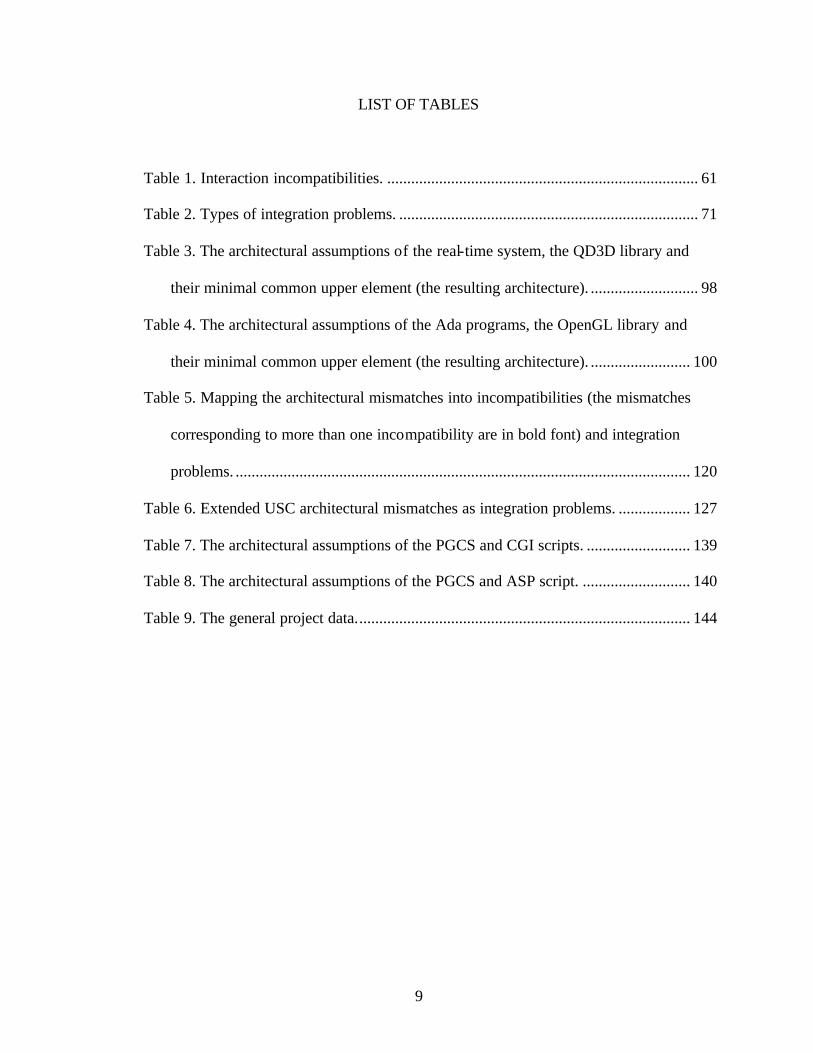
LIST OF TABLES
Table 1. Interaction incompatibilities. .............................................................................. 61
Table 2. Types of integration problems. ........................................................................... 71
Table 3. The architectural assumptions of the real-time system, the QD3D library and
their minimal common upper element (the resulting architecture). ........................... 98
Table 4. The architectural assumptions of the Ada programs, the OpenGL library and
their minimal common upper element (the resulting architecture). ......................... 100
Table 5. Mapping the architectural mismatches into incompatibilities (the mismatches
corresponding to more than one incompatibility are in bold font) and integration
problems. .................................................................................................................. 120
Table 6. Extended USC architectural mismatches as integration problems. .................. 127
Table 7. The architectural assumptions of the PGCS and CGI scripts. .......................... 139
Table 8. The architectural assumptions of the PGCS and ASP script. ........................... 140
Table 9. The general project data.................................................................................... 144

10
LIST OF FIGURES
Figure 1. COTS Usage and integration problems. ............................................................ 15
Figure 2. The models used for the proposed COTS reuse process. .................................. 16
Figure 3. The models used for the proposed COTS reuse process. .................................. 48
Figure 4. COTS-related activities in a life-cycle. ............................................................. 51
Figure 5. Ordering of the types of packaging. .................................................................. 56
Figure 6. Ordering of the types of control. ....................................................................... 57
Figure 7. Ordering of the types of information flow. ....................................................... 57
Figure 8. Ordering of the types of synchronization. ......................................................... 57
Figure 9. Ordering of the types of binding. ...................................................................... 58
Figure 10. Interactions of software components. .............................................................. 60
Figure 11. High- level project characterization. ................................................................ 77
Figure 12. High- level project characterization. ................................................................ 80
Figure 13. High- level COTS products characterization. .................................................. 81
Figure 14. COTS functionality assessment....................................................................... 90
Figure 15.COTS architecture design. ................................................................................ 95
Figure 16. Low-level project characterization. ............................................................... 101
Figure 17. Low-level COTS products characterization. ................................................. 102
Figure 18. COTS integration (design). ........................................................................... 108
Figure 19. Ordering of the types of triggering. ............................................................... 128
Figure 20. Ordering of the types of spawning. ............................................................... 129
Figure 21. A possible architecture for the upgraded system........................................... 141

11
Figure 22. The distribution of the incompatibility model usefulness evaluation along
students with different level of software development experience. ......................... 150
Figure 23. The distribution of the integration solutions usefulness evaluation along
students with different level of software development experience. ......................... 150

12
Chapter 1. Introduction
1.1. Problem statement
Commercial-off-the-shelf (COTS) software is developed by a third party,
usually a commercial vendor, and intended to be part of a new software system.
Developed by professionals in the area, COTS software can possess high quality and
provide very sophisticated packaged functionality. Thus, COTS products reuse can
help software developers to reduce the development effort and increase the product’s
quality [Gentleman 97], [Fox et al. 97], [Voas 98a], [Voas 98b]. Other benefits are
quick feasibility of demonstrations and support of COTS products by their vendors
[Fox et al. 97]. These benefits of COTS reuse make it an important issue in software
engineering.
When a software system is developed around a COTS product, it is called a
"COTS-solution system." If a system includes a large proportion of COTS products it
is called "COTS-intensive" [Wallnau et al. 98a]. However, the term "a COTS-based
system" is generally used [Brownsword et al. 98], for all purposes.
There are several groups of COTS products that have been successfully used
in software development [Vidger et al. 98]:
- geographic information systems (GIS)
- graphics user interface (GUI) builders
- office automation software, such as calendars, word processors,
spreadsheets, etc.
- e-mail and messaging systems

13
- databases
- operating systems, including low-level software such as device drivers,
window systems, etc.
However, in practice, the COTS products did not turn out to be a “silver
bullet”. Apart from the general reuse problems (selection, integration, maintenance,
etc.), COTS products are plagued by their own specific problems [Fox et al. 97]:
- Incompatibility: COTS component may not have the exact functionality
required; moreover, a COTS product may not be compatible with in-house
software or other COTS products;
- Inflexibility: usually the source code of COTS software is not provided, so it
cannot be modified;
- Complexity: COTS products can be too complex to learn and to use imposing
significant additional effort;
- Transience: Different versions of the same COTS product may not be
compatible, causing more problems for developers.
Not surprisingly, some reports admit considerable difficulties of COTS usage
[Garlan et al. 95], [Swanson, MacMagnus 97]. Even successful cases of COTS usage
involved more effort than expected [Sparks et al. 96], [Medvidovic et al. 97], [Vidger,
Dean 97]. We simply do not know how many projects failed due to problems caused
by COTS, because it is unlikely that developers would ever report such a failure.
Nevertheless, many publications warn about serious COTS-related problems [Dargan
95], [Carney, Oberndorf 97], [Brownsword et al. 98], [Boehm, Abts 99].

14
We believe that the reason for the COTS integration problem, which is the
main concern of the present study, is that COTS products are not developed for a
specific application, and since they are integrated into a system, they are used in a
certain context with its dependencies.
The system, which consists of software and hardware components, is
developed within specific development and target environments. Since COTS
products can interact with different components and parts of the system
environments, plugging the COTS software into the system can require integration.
The present work considers the following types of integration problems: functional,
non-functional, architectural style, architectural, and interface (Figure 1). To achieve
the successful reuse of COTS products, all integration problems must be overcome.
This problem is deepened by lack of COTS-specific software reuse models, so
developers do not always understand the problems, and the known reuse approaches
for in-house software do not work very well because of specific COTS-related
problems. Existing COTS research, which is to be discussed later, has not provided a
widely accepted COTS reuse model.
Thus, the objective of this study is to develop a model for COTS reuse with
emphasis on evaluation and integration that:
1. takes into account development of in-house software;

15
2. includes both COTS evaluation and integration;
3. makes few assumptions about the system and COTS products (any type of
life-cycle, COTS software, in-house software, architecture, etc.);
4. includes practical recommendations to assist the developers in reusing COTS.
Figure 1. COTS Usage and integration problems.
This model addresses the COTS incompatibility problem, and helps
developers to select COTS products based on their predicted integration effort and to
perform the actual integration. The practical use of this model will be the reduction in
development effort due to the selection of appropriate COTS products and the use of
packaged integration guidelines.
Hardware
To be
COTS
Software
System
Environment
Target
Development
Functional problems
Non-functional problems
Architectural style problems
Architectural problems
Interface problems

16
1.2. The proposed approach and organization of the dissertation
We believe that the COTS reuse problem is very complex, and a simple
solution will not suffice. As it will be shown in the chapter on the related research, the
existing models of COTS reuse do not provide a universal solution for COTS
selection and integration. Thus, the proposed approach is a set of related models
(Figure 2); the arrows show dependencies between the models and point to the
dependent models.
Figure 2. The models used for the proposed COTS reuse process.
1. The architectural model is intended to identify an appropriate architectural
style for a COTS-based system. This model uses a set of variables that
describes architectural properties of software components and systems and
builds the partial relation of compatibility on the values of these variables.
One architectural assumption is compatible with another one, if a component
with the second assumption can be converted into a component with the first
assumption. For a set of components, an assumption compatible with the
assumptions of each component can be an assumption of the system that can
use all the components of the set. This approach will help to identify the
Architectural model Incompatibility model
Integration problems model
Comprehensive reuse model
Effort estimation model
COTS activity model

17
architectural style of the system into which the software components will be
integrated.
2. The incompatibility model helps to detect early the integration issues. This
model first classifies components of the system and its environment, and then
it classifies failures of interactions between software and other components
(incompatibilities) as syntactic and semantic-pragmatic. The latter are further
sub-classified with respect to the exact number of components that cause an
incompatibility; there are 1-, 2-, and n-order semantic-pragmatic
incompatibilities. If software developers are going to integrate a software
component, they can analyze the components that will interact with it to
identify the potential incompatibilities.
3. The integration problem model helps to find solutions for integration issues.
The architectural and incompatibility models aid the integration problem
model. This model classifies the integration problems according the feasible
strategies for their solutions, such as re- implementation, modification,
tailoring, architecture changes, architectural style changes, and glueware. It is
also possible to map an incompatibility into an integration problem, so that if
the incompatibility model helps to find a potential integration issue, the
integration problem model will help to find a solution for this issue.
4. The comprehensive reuse model offers a mechanism for identifying the
appropriate information. This model originally was a general model for reuse
of any kind of knowledge, but in this work, it was adapted for COTS
integration. This model provides template to describe the system

18
requirements, the candidate reuse components, including COTS products, and
procedures for tailoring the candidate reuse components so that they would fit
the system requirements.
5. The effort estimation models helps to estimate the integration effort. This
model defines an algorithm that accepts as its input system requirements,
COTS products characterization, and the organization’s productivities. Based
in the inputs, the algorithm then calculates an estimation of effort required to
integrate the COTS products into the system for the given organization.
6. Finally, the COTS activity model provides the entire COTS’ evaluation and integration process. This model uses the comprehensive reuse model, the
integration problems model, and the effort estimation model. The COTS
activity model adds COTS-specific activities to the development life-cycle, so
that COTS products can be evaluated and integrated during the development
process.
The architectural, incompatibility, integration problems, and COTS activity
models present the contribution of this work. The comprehensive reuse model was
developed by Basili and Rombach [Basili, Rombach 91] for reuse of objects of any
kind, and it was tailored for reuse of COTS products in this work. The effort
estimation model, while an original contribution, is not fully developed yet.
Due to the complexity of the problem and the solution, it does not seem that it
is easy to validate the entirety of the proposed models. Nevertheless, we present in
19
this work a partial analytical and empirical validation of the incompatibility,
integration problem, and architectural models. This is also a contribution of this work.
This dissertation is organized as follows:
- The rest of Chapter 1 gives detailed notions of COTS and software component
reuse (Section 1.3) and coverage of COTS-related problems beyond those
mentioned in the present section (Section 1.4);
- Chapter 2 gives an overview of related work;
- Chapter 3 provides a brief description of the proposed COTS reuse process
and its subsidiary models;
- Chapter 4 contains detailed description of the COTS reuse process and an
example of its usage;
- Chapter 5 contains an analytical validation of the incompatibility and
integration problem models using the architectural mismatch model from the
University of Southern California [Gacek 97];
- Chapter 6 describes an empirical case study based on data from software
engineering class projects at the Univeristy of Maryland;
- Chapter 7 is the summary of this dissertation.
1.3. COTS definition and software reuse notions
The acronym "COTS" stands for Commercial-Off-The-Shelf, so we must
define what is "commercial", and what is "off-the-shelf". The official definition of the
20
term "commercial" is given in the Federal Acquisition Regulations [Oberndorf 97]. A
commercial item is defined as follows:
1. property customarily used for non-governmental purposes and has been
sold, leased, or licensed (or offered for sale, lease or license) to the general
public
2. any item evolved from an item in (1) through advances in technology and is
not yet available commercially but will be available in time to satisfy the
requirement
3. any item that would satisfy (1) or (2) but for modifications customarily
available in the commercial marketplace or minor modifications made to meet
Federal Government requirements
4. any combination of items meeting (1) - (3) above
5. services for installation, maintenance, repair, training, etc. if such services
are procured for support of an item in (1), (2), or (3) above, as offered to the
public or provided by the same work force as supports the general public; or
other services sold competitively in the marketplace
7. a non-developmental item developed exclusively at private expense and sold
competitively to multiple state and local governments
As for the term "off-the-shelf", it can mean that the item is not custom-built,
but is available on the market without attachment to any particular project, and it is
the user who is responsible for its deployment and usage. It is suggested in
[Oberndorf 97] that the salient characteristics of a COTS product are: it exists a

21
priori; it is available to the general public, and it can be bought (or leased, or
licensed).
There are different viewpoints regarding the issue whether or not COTS
software users can change it. One definition of a COTS component is "a software
component that has been bought from a third party and that a developer uses on an as-
is basis" [Vidger, Dean 97]. "If you modify the source code, it's not really COTS -
and its future becomes your responsibility" is a similar viewpoint [Boehm and Abts
99]. John McDermid suggests another definition that does not imply that COTS
products cannot be modified. According to him COTS software products are
"standard commercial software developed without any particular application in mind"
[McDermid, Talbert 98]. A classification of software components with respect to
their source and modification assumes that the source of a software component and
the possible modifications of it are independent variables, and that the source code of
a COTS component is available to its users [Carney, Long 00].
In this work, COTS products are assumed to be any reusable software
components bought from a third party which can be used in one of following ways:
- Black box reuse: no changes are allowed in the software that is being
reused; the source code is unavailable [Neighbours 94].
- Glass box reuse: no changes are allowed, but the source code is available
and can be seen [Workshop 89].

22
- Gray box reuse: the source code is available and formally controllable
changes are allowed [Workshop 89]. Another definition of gray box reuse
is when the component provides its own extension language or application
programming interface (API) thus allowing users to adapt it [Haynes et al.
97].
- White box reuse: everything can be changed [Neighbors 94].
Mostly we expect black box reuse for COTS products, because it is unlikely
that any changes can be made due to unavailability of the source code and vendor's
copyright. In the current state-of-practice most COTS software products are usually
available as black boxes, and we shall be concerned primarily with this case.
Nevertheless, it is possible that some COTS products can be reused as glass box, gray
box, and even white box reuse, so these cases should not be ruled out completely.
As for the term "software component", it can be defined [Meyer 99] as a
program element with the following properties:
- other program elements (clients) may use the element
- the clients and their authors do not need to be known to the element's
authors
The following classification of components is given in [Meyer 99]:
1) by level of software process task
- analysis components, which take advantage of reusability for system
modeling

23
- design components, also known as patterns
- implementation components that are actually executable pieces of
software ready to be integrated in a working software system
2) by level of abstraction
- functional abstraction, such as subroutines and functions in traditional
libraries, each of which covers one particular function
- casual grouping, such as Ada packages or C files, gathering arbitrarily
related elements
- data abstraction, such as classes in OO languages, each of which covers a
type of object
- cluster abstraction (or framework) which covers a set of related data
abstractions intended to work together according to preset schemes
- system abstraction, which is the case of coarse-grained binary components
such as COM and CORBA components; MS Word, used as a component,
falls into this category
3) by level of execution:
- static components integrated at compile or link time which are not
changeable without recompiling
- replaceable components, like static components, but with variants that can
be substituted dynamically
- dynamic components integrated at execution time
4) by level of accessibility:

24
- interface descriptions with no source available; many commercial
components are distributed in this form
- complete source with little or no information hiding
- information hiding, with reuse through the interface and source available
for inspection, discussion, and correction
Commercially available components may vary significantly in size,
granularity, and packaging; COTS software component then can be a procedure, a
class, a whole library, a stand-alone application, an application generator, or even a
problem oriented language [Gentleman 97].
1.4. COTS reuse issues
We discuss the issues associated with COTS reuse besides those mentioned in
the problem statement (Section 1.1).
First, software development using COTS has a life cycle different from the
life-cycle of conventional software development. A study at NASA Flight Dynamic
Division [Parra et al. 97] showed that the COTS-based development process being
applied there had the following steps:
1. requirement analysis
2. package identification, evaluation and selection
3. non-COTS development
4. glueware requirements and development

25
5. system integration and test
6. target system installation and acceptance test
7. discrepancy resolution
8. sustaining engineering
The whole development process consisted of a non-COTS development process
(steps 1, 3, 5, 6, 7, and 8), which used the traditional waterfall software development,
and COTS development (steps 2, 4, and 5). It was found that information flows bi-
directionally between COTS and non-COTS processes.
Although COTS products do not require design and implementation, they
have the following activities in the project life cycle [Wallnau et al. 98a]:
- examine the marketplace
- qualify and select one or more products
- adapt the product to some specific system requirements
- assemble the system
- update the products as needed
The first two activities relate to the procurement of COTS products, which itself is a
hard task [Breslin 86], [Connell, Shafer 87], [Kontio 95], [Maiden et al. 97], [Wallnau
et al. 98b]. This process is complicated by the characteristics of the products, and the
need to satisfy many requirements. For example, an approach for COTS selection,
The Systematic Process for Reusable Software Component Selection (OTSO), has the
following phases [Kontio 95]:
- search: all relevant candidates are looked for

26
- screening: the best of them are picked for further evaluation
- evaluation: they are evaluated according to a number of criteria
- analysis: on the results of the evaluation the best candidate is chosen
- deployment: the chosen alternative is used in development
- assessment: the success of reuse of the component is assessed
COTS products selection must start early in the project so that the COTS
products will be available in time for their integration. A possible risk here is to delay
the choice and consequently slip the schedule. Another risk is to make a poor choice,
which can make the integration very difficult and deteriorate the quality of the
product.
Integrating a component into the system may require tailoring the component
or writing a considerable amount of code for wrappers and glue [Vidger, Dean 87],
[Vidger et al. 98]. There is a risk that integration can be more expensive than
implementing the required functionality from scratch [McDermid, Talbert 97]. COTS
products integration is considered in detail in the next chapter.
After the system is developed, maintenance of a COTS-intensive system is a
specific problem, because of updates of the COTS products and replacements of
COTS products in the system with other ones [Hybertson et al. 97]. On the other
hand, the vendor can halt support when the product is still in use [Gentleman 97].
Another problem with COTS products is security [Voas 98b], [Lindqvist, Jonsson

27
98], [Zhong, Edwards 97]. There is no guarantee that a purchased product is safe; it
can be just a memory leak, or even a Trojan Horse that will destroy the entire system.
Finding and isolating faults in a COTS-based system can be very difficult, because
the source code may not be available, and the COTS products and their interactions
can be very complex. In this case special techniques must be used [Hissam, Carney
00]. Finally, COTS products require developers to be familiar with them, and there is
a risk that the learning curve is very steep [Gentleman 97]. This will consume a lot of
developers' time and effort, again presenting a serious threat to the schedule.
Generally, although use of COTS allows for not writing new software, the
required effort can be comparable to development from scratch. There is evidence
both in support of and against the use of COTS products [Dargan 95], [Carney,
Oberndorf 97]. COTS products are not a universal solution; rather, they require a
careful study every time they are used, and research needs to be done to reduce costs
of COTS usage.

28
Chapter 2. COTS Related Research and the Integration Problem
Identification
A considerable amount of research has been dedicated to COTS software
usage. COTS integration, selection, security, maintenance, and other issues have been
addressed in the previous chapter. This chapter discusses research related to
approaches to the evaluation and the integration of COTS software products.
The first two sections outline known approaches to represent information
about COTS.
- Section 2.1 presents the Comprehensive reuse model that helps to identify
information from a COTS component, what it offers, and how to relate the two
[Basili, Rombach 91].
- Section 2.2 describes specification templates for COTS intended to present
structured information about COTS products [Dong et al. 99].
- Section 2.3 presents research dedicated to non-functional properties of COTS
products [Kunda, Brooks 99], [Schneidewind 99]. This research helps to classify
the non-functional integration problems used in the proposed integration problems
model.
- Section 2.4 describes the existing effort estimation models for COTS
development [Smith et al. 97], [Boland et al. 97], [Abts et al. 00]. The limitations

29
of these models are discussed to explain why another effort estimation model was
proposed in this work.
- Section 2.5 describes a general process for COTS integration (ICAP) [Payton et
al. 99]. This and the following three sections describe the known component
integration approaches. The limitations of these approaches are given, which
justify the need for the integration model proposed in the present work.
- Section 2.6 gives an overview of COTS integration models: the integration
approach for distributed architectures [Vidger, Dean 97], the layered architecture
C2 [Medvidovic et al. 97], Infrastructure Incremental Development Approach
[Fox et al. 97], and the four-fold integration process [Brownsword et al. 00].
- Section 2.7 outlines standard architectures for component integration (OMA,
COM, etc.) [Baker 97], [Box 98], [Giguere 97], [Dashofy et al. 99].
- Section 2.8 relates to scripting languages [Ousterhout 98].
- Section 2.9 gives an overview of the USC model of architectural mismatches
[Gacek 97]. This model will be used later in Chapter 5 for analytical validation of
the proposed incompatibility and integration problems models and expanding the
integration problems classification.
- Section 2.10 gives general approaches to software components integration [Davis,
Williams 97], [Garlan et al. 95], [Shaw 95]. These works show how the

30
integration process, proposed in this work, relates to the current state-of-the-art in
component integration techniques.
- Finally, section 2.11 concludes the chapter, presenting limitations of existing
research and giving the reasons for conducting the present study.
2.1. The comprehensive reuse model
The comprehensive reuse model is intended for reusing different artifacts,
such as products, processes, and knowledge [Basili, Rombach 91]. The model
describes the transformation of reuse candidates into required objects through a reuse
process.
Each reuse candidate is an object; its interactions with other objects constitute
the object interface, and the characteristics left by the environment in which the
object was created are called the object context. The system, in which the object is
integrated, has its own system context. The reuse process consists of reuse activities.
Each activity has its own means of integration or activity interface. The
organizational support provided for the experience transfer across different projects is
called the activity context.
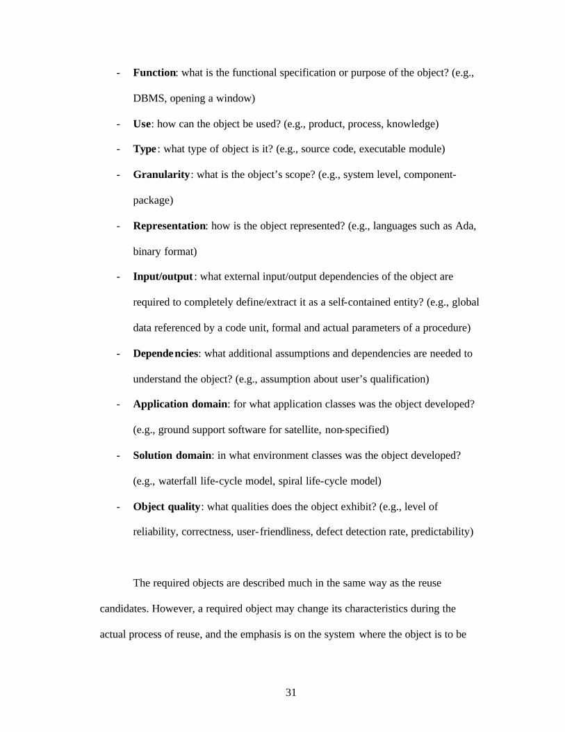
The reuse candidates are characterized in terms of:
- Name : what is the object’s name? (e.g., Oracle, open_window)
31
- Function: what is the functional specification or purpose of the object? (e.g.,
DBMS, opening a window)
- Use: how can the object be used? (e.g., product, process, knowledge)
- Type : what type of object is it? (e.g., source code, executable module)
- Granularity: what is the object’s scope? (e.g., system level, component-
package)
- Representation: how is the object represented? (e.g., languages such as Ada,
binary format)
- Input/output : what external input/output dependencies of the object are
required to completely define/extract it as a self-contained entity? (e.g., global
data referenced by a code unit, formal and actual parameters of a procedure)
- Dependencies: what additional assumptions and dependencies are needed to
understand the object? (e.g., assumption about user’s qualification)
- Application domain: for what application classes was the object developed?
(e.g., ground support software for satellite, non-specified)
- Solution domain: in what environment classes was the object developed?
(e.g., waterfall life-cycle model, spiral life-cycle model)
- Object quality: what qualities does the object exhibit? (e.g., level of
reliability, correctness, user- friendliness, defect detection rate, predictability)
The required objects are described much in the same way as the reuse
candidates. However, a required object may change its characteristics during the
actual process of reuse, and the emphasis is on the system where the object is to be

32
reused. The distance between the characteristics of a reused candidate and the
required object in the system must be bridged in the reuse process.
The reuse process can consist of several activities. Each reuse activity is
characterized in terms of:
- Name : what is the name of the activity? (e.g., identify_COTS,
evaluate_COTS)
- Function: what is the function performed by the activity? (e.g., select
candidate objects that satisfy certain characteristics of the reuse requirements)
- Type : what is the type of the activity? (e.g., identification, evaluation)
- Mechanism: how is the activity performed? (in the case of identification, e.g.,
by name, by function, by type)
- Input/output : what are the explicit input and output interfaces between the
reuse activity and the enabling software evolution environment? (in the case
of identification, e.g., description of the reuse candidates and reuse
requirements)
- Dependencies: what are other implicit assumptions and dependencies on data
and information regarding the software evolution environment? (e.g., the time
at which reuse activity is performed, relative to the enabling development
process).
Although this model was originally developed for general reuse of processes,
products, and knowledge, in the present study we tailor it for COTS software

33
products. For example, it is difficult to measure the object quality of a COTS software
component (especially if the source is not available), if the solution domain is not
defined exactly (a general purpose COTS library). On the other hand, additional fields
can be added to this characterization scheme, e.g., the target platform field was added
to the scheme in the present work.
2.2. Specification templates for COTS
A specification template, similar to the comprehensive reuse characterization
schemes, has been suggested for COTS components in [Dong et al. 99]. This template
allows describing COTS software components in a uniform way. The template has
the following structure:
- component name: the name of the component describes its identity.
- functional interfaces
- structural aspects of the services: syntactical information, such as names,
types and number of parameters, structural design information, and other
static information
- behavior aspects of the services: the state transition diagrams illustrating
the control model, the data flow diagrams denoting the data model, the
collaboration diagrams describing component behavior interactions, such
as call sequences, and other dynamic information
- assumptions: preconditions of using the functionality, architectural design,
the global architectural design, and the construction process
- promises: post-conditions

34
- invariants
- temporal properties: time-related constraints
- non-functional properties: performance, security, reliability, concurrency, etc.
- applicability: as operating system, specific languages, tools, environments
- standards: as CORBA, COM, and JavaBeans
- related components
- similar components: components offering similar services
- collaborators: components with which this component can collaborate
- sample uses
2.3. Non-functional characteristics of COTS products
Factors that support COTS component selection have been studied in [Kunda,
Brooks 99]. A total of 51 factors related to social- technical criteria, evaluation
(assessment), and the search for alternatives have been found. The social- technical
criteria include compliance issues (functionality), socio-economic (non-technical)
issues, product quality characteristics, and architectural styles and frameworks.
Assessing COTS products’ reliability, maintainability, and availability (RMA)
is considered in [Schneidewind 99]. These important aspects are hard to evaluate in
COTS products because the source code is usually unavailable, but developers must
address these issues to prevent deterioration in quality. In order to provide developers
information on their RMA, it was proposed to certify COTS products.

35
2.4. Integrating Components Architectures Process (ICAP)
An integration process based on assessment of interoperability between
software components has been offered in [Payton et al. 99]. The suggested Integrating
Components Architectures Process (ICAP) consists of three phases:
- pre-integration: describes the architectures of participating components and
determines interoperability problems
- correspondence identification: choosing an integration strategy
- integration: implementation, evaluation, and testing
ICAP lets developers predict and overcome architectural conflicts between integrated
software components. While is somewhat similar to the process proposed in the
present study, ICAP is too high- level to be really applicable.
2.5. Cost estimation models for COTS-oriented software development
There are several existing methods for estimating the cost of COTS
integration. COCOMO and SLIM cost estimation models have been modified for
systems using COTS [Smith et al. 97], [Boland et al. 97]. Another cost estimation
model specifically developed for COTS products is COCOTS (COnstructive COTS
estimation cost model) [Abts et al. 00]. This model is a modification of COCOMO for
software processes that use components when the source code is unavailable (black-
box COTS components). The results look satisfactory, and other estimation
techniques can be adjusted for COTS development for early cost estimation.
Nevertheless, one must keep in mind that they merely give a numerical estimation,
and do not provide guidance for the integration process. Further, some important

36
factors, such as the system architecture, can be overlooked, giving an incorrect effort
estimation. Finally, since these models require data from many projects across the
industry to calibrate their parameters the data for such calibration may be scarce.
2.6. COTS integration models
We can now consider specific COTS integration methods that have been
developed and applied. The first two integration methods use specific software
architectures that are more suitable for COTS integration than the conventional ones,
while the third integration method is based on a special COTS-oriented life-cycle.
In the first integration approach, it is suggested [Vidger, Dean 97] that all
components must be wrapped so that all interactions are performed only through the
wrappers; further, glue provides interconnections between them. Although this
approach is very sound and promises a solution of the COTS integration problem, it
requires a very specific architecture. The actual software system, which was built
using this approach, integrated ODBC-compliant databases, ActiveX components,
object libraries, and web servers. The COTS components were not tightly coupled, so
they worked together in a distributed system. However, this approach may not work
as well for closely coupled COTS software products, such as those described in
[Garlan et al. 97]. It is clear that the types of components that can be integrated using
this method might be limited.

37
Another type of architecture suitable for COTS integration is C2 [Medvidovic
et al. 97], which is a component- and message-based architectural style. C2
architecture is a hierarchical network of concurrent components linked together by
connectors (message routing devices) in accordance within a set of style rules. C2
allows the use of heterogeneous components with their internal architecture. It has
asynchronous message passing and makes no assumption on shared address space, or
a single thread of control. These features allow reusing COTS products with different
characteristics. Research has been conducted on using different off- the-shelf
middleware in C2 architecture [Deshofy et al. 99]. However, C2 uses a layered style,
i.e., components of upper layers can send messages only to components of lower
layers thus limiting the number of COTS that can be used within this architectural
style.
One more integration approach is to use a special development life-cycle [Fox
et al. 97], the Infrastructure Incremental Development Approach (IIDA), which is a
combination of the classical waterfall development model and the spiral development
model, and especially designed fo r COTS integration. The central structure of IIDA is
the technology-based layer of the application, built upon the business-specific layer.
In IIDA each version of the infrastructure is an increment that is integrated into the
existing infrastructure baseline. Within each version, development proceeds in time-
sequenced stages with iterative feedback to the preceding stages of definition and
analysis, functional design, physical design, construction, and test. Stages of the
development cycle are augmented with a series of structured prototypes for COTS

38
product evaluation and integration. For each COTS family, the prototypes evolve
from initial analysis prototypes for a make/buy decision to a series of design
prototypes for COTS product selection and detailed assessment, and, finally, to a
demonstration prototype that becomes part of the development test bed.
Another proposed COTS integration process consists of four types of
activities [Brownsword et al. 00]:
- engineering activities:
- requirements activities
- architecture and design activities
- marketplace activities
- construction activities
- configuration management activities
- deployment and maintenance activities
- evaluation activities
- business activities:
- COTS business case activities
- COTS cost estimation activities
- vendor and supplier relationships activities
- license negotiation activities
- project-wide activities:
- CBS (COTS-based systems) strategy activities
- COTS risk management activities

39
- CBS trade-offs activities
- cultural transition activities
- contract activities
This model helps developers to build COTS-based systems through a timely
combination of the activities of these four groups. However, the model primarily
addresses the manager’s perspective of software development, and it is less helpful
for developers who need to do COTS integration.
2.7. Architectures for component integration
Other COTS integration work regards the use of COTS to support integration.
When integrating COTS products, some other suitable COTS products can be used as
glueware. Two groups of software products seem to be useful for this purpose:
component-based architectures with their middleware (OMA/CORBA,
COM/ActiveX, JavaBeans), and scripting languages (Perl, Tcl, JavaScript, ReXX,
etc). Other standards, such as HTTP and CGI, can also be helpful for COTS
integration; in practice, Perl and ActiveX are used [Vidger, Dean 97].
Component standards, such as OMA/CORBA, COM/ActiveX, and
JavaBeans, have emerged recently as an attempt to create open architectures oriented
for reuse of components.
40
Object Management Group [Baker 97] proposes OMA (Object Management
Architecture) and its underlying architecture CORBA (Common Object Request
Broker Architecture) as a standard means for remote procedure calling and methods
invocation between objects, which can be implemented in different programming
languages. OMA also supports full object-orientation including inheritance. Objects
that are compliant with CORBA can be easily integrated using it; if they are not
compliant, a CORBA-compliant wrapper must be implemented for them.
The Microsoft Corporation created its own object-based Component Object
Model (COM) and an ActiveX interface system based on it [Box 98]. This is a binary
standard that allows making calls between different objects, and distributed COM
(DCOM) also allows for objects on different computers. COM does not support full
object orientation (i.e., it does not support inheritance), but instead supports
aggregation. A drawback of COM is that it only works on Win32 platforms.
JavaBeans is a component architecture for Java-based objects [Giguere 97].
Another off- the-shelf middleware for Java is Java Remote Method Invocation (Java
RMI) [Dashofy et al. 99].
Besides the commercial component architectures listed above, there exists
research devoted to combining different architectural styles and software components
with different architectural assumptions [Abd-Allah, Boehm 96], [Gacek 97].
Although these works provide a good overview of possible architectural mismatches,
41
they do not provide solutions and do not take into account other integration problems.
Later in this work, we shall show correspondence between their model and our
model, and propose solutions for their mismatches.
2.8. Scripting languages
Other COTS products that can be used for integration and glueing are
scripting languages, which offer another solution for COTS integration [Ousterhout
98]. They are intended for operating with components written in system programming
languages; for example, Visual Basic is a scripting language for objects implemented
in Visual C++, and JavaScript is a scripting language for HTML and Java. The
scripting languages describe the interaction protocol of components. Scripting
languages can be used only for components that are designed using specific
conventions, so that they are not a universal solution for COTS integration.
2.9. The USC model of architectural mismatches
Architectural mismatches between software components were studied at the
University of Southern California (USC). One of their most recent works [Gacek 97]
describes 23 such architectural mismatches. These mismatches were found and
classified using the following conceptual features:
- dynamism (a system can spawn new components dynamically or they all exist
statically)
- data transfers (data and control information flows)
- triggering (events can or cannot be triggered automatically)

42
- concurrency (the system does or does not permit concurrent subsystems, such
as threads, processes, etc.)
- distribution (the system is based on a single machine or has subsystems on
different ones)
- layering (the system has or does not have a rigid hierarchy of component
layers)
- encapsulation (the system has restriction for accessing some components)
- termination (whether the system terminates or does not terminate its
execution)
Besides the conceptual features above, the classification of mismatches involves
different types of architectural connectors between software components:
- call
- spawn
- data connector
- shared data
- triggered call
- triggered spawn
- triggered data transfer
- shared machine
Connectors and conceptual features define architectural mismatches; for
example, the spawn connector and the conceptual feature of dynamism define a
mismatch when a spawn is made into a subsystem, which originally forbade them.

43
Not all combinations of connectors and conceptual features cause a mismatch, and
some combinations correspond to more than one mismatch. In Chapter 5 we shall
discuss all the architectural mismatches in connection with proposed models.
2.10. The Problem of COTS Products Integration
Although use of COTS products has several issues, we will consider only the
issue of integration and the effect of the integration cost on COTS selection.
COTS components can suffer from general inter-component mismatches; for
example, representation, communication, packaging, synchronization, semantics,
control, and other properties [Shaw 95]. However, not all of them can work for the
black-box reuse, which is the main case for the COTS products. To overcome these
mismatches between components A and B, the following techniques can be used
[Shaw 95]. It is usually possible to consider A as a COTS software component and B
as an in-house component, since A and B in these examples are symmetrical.
1. Change A's form to B's form: by completely rewriting one of the
components to work with the other. Rewriting an in-house component in
order to match the COTS component is feasible, but it can be very
expensive depending on the in-house component.
2. Publish an abstraction of A's form: APIs publish the procedure calls used
to control a component, and in addition, Open Interfaces usually provide
some abstractions. The feasibility of this approach depends on whether an
abstraction of a COTS component is available.

44
3. Transform from A's form to B's form on the fly: some distributed systems
do on-the-fly conversions from big-endian (the most significant byte of a
word is stored first) to little-endian (the most significant byte of a word is
stored last) representations. This approach may require very complex and
expensive software for on-the-fly conversion.
4. Negotiate to find a common form for A and B: modems commonly
negotiate to find their fastest common protocol. This approach seems to be
achieved for hardware only at this time.
5. Make B multilingual: a portable Unix code will run on many processors,
and implementing multilingual in-house software is feasible, but can be
expensive.
6. Provide B with import/export converters: some applications provide
representation conversion services. This can work if there are
representation mismatches (data format, etc.).
7. Introduce an intermediate form: it can be used as a neutral base for
components with different representations. Feasibility of this technique
will depend on whether the COTS component supports an intermediate
form.
8. Attach an adapter or wrapper to component A: some code can be written
to leverage the difference between the interacting components. Writing a
wrapper is a flexible solution; the wrapper can be tailored for any
particular mismatch.

45
9. Maintain parallel consistent versions of A and B: A and B can maintain
their own different forms, which depends on the availability of parallel
forms of COTS software; maintaining parallel forms for in-house software
can also be a problem.
It seems that the most common integration technique, especially for COTS and black-
box reuse is writing glueware that can be of different types [Vidger, Dean 97].
- Wrappers that are software designed and implemented to provide the only
access to the wrapped component;
- Glue that is the software (middleware) that manages the integration of the
components;
- Tailoring that enhances the functionality of a component in ways that are
supported by the component vendor (gray-box reuse).
A serious challenge for COTS integration can be differences in architectural
assumptions among different COTS products, and between the COTS products and
the target system [Davis, Williams 97], [Garlan et al. 95], [Shaw 95]. It was
determined that using just four COTS products in one project with different
architectural styles can increase the required effort [Garlan et al. 95].
2.11. Conclusions
Use of COTS products in software development should now grow. There are
many advertisements for companies which include COTS integration in their
services, on the Internet, and reports about projects that used COTS products are

46
available [Garlan et al. 95], [Boland et al. 97], [Parra et al. 97], [Rowe 97], [Swanson,
MacMagnus 97], [Vidger, Dean 97], [Balk, Kedia 00], [Crnkovic, Larsson 00],
[Morisio et al. 00], [Seacord 00]. Although currently far from being a "silver bullet,"
COTS products are a reasonable approach for software development. An important
issue of COTS reuse is the integration of COTS components into the system. It may
not be an easy task because the problem of software reuse was not solved
satisfactorily for industrial software development. Moreover, COTS products are
more difficult to integrate than in-house software due to their incompatibility,
inflexibility, complexity, and transience. Usually COTS products must be tailored,
and some glueware written for their integration. The known approaches for
integration use either a special development process [Fox et al. 97], or creating
special architectures with specific types of COTS products [Vidger et al. 97],
[Medvidovic et al. 97]. Nevertheless, we can conclude that the existing COTS reuse
research is not entirely satisfactory, and the following problems persist:
1. Too high- level – sometimes researchers approach a problem from a manager’s
viewpoint, omitting low-level details, thus making their ideas less useful for
developers.
2. Fragmentary – sometimes researchers attack a particular problem, such as
integration, evaluation, or security, without connections to other issues. For
example, typical works on COTS evaluation do not contain detailed
information on COTS integration, although the cost of COTS usage should
include integration costs.

47
3. Narrow – sometimes there are too many specific assumptions. For example,
the proposed architectures for integrating COTS products use narrow
assumptions about the COTS products and the architectural design of the
system.
Practitioners might be interested in a general approach for COTS reuse, which
would include COTS evaluation, integration, and the connection between them, and
which is the objective of this study. Although the proposed model is still somewhat
fragmentary, because it addresses primarily COTS selection and integration, it is an
attempt to find a balance between the high- levelness and the narrow, while trying to
be both grounded and general.

48
Chapter 3. The proposed solution for COTS integration and evaluation
The proposed approach for COTS integration and evaluation process is based
on the following models (Figure 3):
Figure 3. The models used for the proposed COTS reuse process.
1. Architectural model [Yakimovich et al. 99] helps to identify an appropriate
architectural style for integrating COTS products into the system.
2. Incompatibility model [Yakimovich et al. 99b] is a low-level model of
interactions that helps early prediction of the possible incompatibilities between
components (including COTS software) of a software system and its environment.
3. Integration problems model [Yakimovich et al. 99b] gives a high- level
classification of integration issues and possible integration strategies to overcome
them.
4. Effort estimation model for COTS integration giving means to estimate COTS
integration effort.
Architectural model Incompatibility model
Integration problems model
Comprehensive reuse model
Effort estimation model
COTS activity model

49
5. Comprehensive reuse model [Basili, Rombach 91] allows for identifying
appropriate information about reuse candidates (including COTS software), the
requirements for the system, and of reuse activities.
6. COTS activity model describes the whole COTS reuse process by augmenting
the software development life-cycle with COTS-specific activities.
First, we give an outline of the COTS activity model showing their
interactions with the other models. Then we present other models (except the
comprehensive reuse model, which was described in Chapter 2), and Chapter 4
provides a full description and an example of application of the COTS activity model.
3.1. The COTS activity model
In this study, we do not assume any particular life-cycle model (e.g., waterfall,
spiral, etc.). However, the proposed model assumes that it is possible to add specific
COTS activities to a software development process that contains the conventional
phases of requirement analysis, design, coding, and testing.
The main idea of the proposed reuse process is to combine evaluation with
integration. The present work evaluates COTS products with respect to the integration
effort only, leaving aside issues such as security, vendor support, maintenance, etc.,
which can be considered in a future work.
We assume that it is impossible to evaluate COTS products during the early
stage of software development because some important information about the project

50
is not yet known, e.g., the system’s architectural style and architecture. If developers
select a COTS product based only on its functionality, there is a risk that they will run
into integration problems later on due to COTS products’ incompatibility with the
system’s architecture. Another assumption about effort estimation is that the
integration strategies (techniques) that are actually applied for overcoming integration
problems must be considered when COTS products are evaluated.
The COTS activity model consists of the following are COTS-specific
activities, which are attached to appropriate life-cycle phases (Fig. 4):
- Organization characterization is intended to obtain information about the
organization to find later effort estimation. This activity does not generally
depend on the particular project, so it may be performed even outside the life-
cycle of a specific project. At this point we already can see a necessity to have a
mechanism for identifying information and for structural presentation, and this is
the reason for using the comprehensive reuse model.
- High-level COTS products and project characterizations collect information
about the COTS market and the project (system’s requirements). The search for
COTS products and their characterization is best performed after the project
characterization, because information about project requirements can focus
market search on specific COTS products. Once a COTS product has been
characterized, information can be stored to avoid a repeat characterization of the
same product in the future.
Requirements analysis
Organization characterization
Project characterization (high- level)
COTS products characterization (high- level)
COTS functionality assessment (effort estimation based on functionality)

51
Figure 4. COTS-related activities in a life-cycle.
- COTS functionality assessment is to obtain an effort estimation based on
functional and non-functional integration issues. This effort estimation uses
information from organization, high- level project, and high- level COTS product
characterizations. If no suitable COTS products are found here then either the
system’s requirements must be renegotiated, or developers must implement the
required functionality.

52
- COTS architectural style design is done early in the design phase. An analysis of
architectural integration issues is done to give an effort estimation based on
architecture. This effort estimation uses information from the organization, high-
level project, and high- level COTS product characterization, and the outcome
affects the requirements and the system’s architecture. If the effort required in
integrating the COTS products into the system’s architecture is too high, then
developers can either find other COTS products, or change the system’s
architecture.
- Low-level COTS products and project characterization are done after the
completion of COTS architecture design, and COTS products are selected to
obtain low-level information necessary for COTS integration.
- COTS integration (design, coding, and testing) is performed to design and
implement glueware. The integration can also include COTS adapting, when
white- and gray-box COTS products are modified in order to fit into the system.
Analysis of architectural and interface integration problems is done using
information from organization, low-level project, and low-level COTS products
characterization. If the cost of the glueware after its design is found to be
prohibitive for further implementation, other COTS products can be selected.
If there are any considerable changes in the organization, in the COTS market,
or in the requirements, then the appropriate COTS activities (organization
characterization, COTS products characterization, and project characterization) can
be performed again, which can cause re- iteration of the whole COTS reuse process.

53
There are three activities that estimate effort: COTS functionality assessment,
COTS architectural style design, and COTS integration (design). The effort
estimations are based on prediction of integration work required for overcoming
incompatibilities between the COTS products and other parts of the system and its
environment. Therefore, the COTS reuse process must include models for estimating
effort, finding incompatibilities, and identifying integration solutions, including
designing the system’s architectural style. These models will be described in the
following sections.
3.2. The architectural model
The architectural style and architecture for a COTS-based system must reflect
the architectural assumptions of the integrated COTS products. In this work, we
consider the following architectural assumptions: component packaging, type of
control, type of information flow, synchronization, and binding [Shaw, Clements 97].
However, this list of assumptions is not final and can change; for example, we have
added triggering and spawning after we performed the analytical validation of the
proposed models (Chapter 5).
First, we introduce the notion of compatibility, which is usually applied to
programming languages, e.g., “compiler X is ANSI compatible,” but in this work the
definition is expanded to include other component characteristics.

54
We say that assumption A is compatible with assumption B, if software
components with assumption B can be relatively easily converted into components
with assumption A. For example, the synchronous type of synchronization is
compatible with the asynchronous type, because asynchronous components can be
made synchronous by adding a loop waiting when a message arrives. If assumption A
is compatible with assumption B then B is convertible into A, and in this case we
write: A=B, or B=A.
If A=B and B=C then it possible to convert a C-compliant component into a
form with assumption B and then into a form with assumption A. Therefore, the
relation among compatible components is transitive.
Assumption C is a common upper element for assumptions A and B if it is
compatible with both (i.e., C=A and C=B). Assumption C is the minimal common
upper element for assumptions A and B if C is their common upper element and there
exists no assumption D such that C=D, C?D, and D is a common upper element for A
and B. We are going to study their possible values with respect to the compatibility
relation and to build partially ordered sets of values for the architectural assumptions;
this will help in integrating COTS software products without additional
modifications.
55
The system’s architecture must allow both for usage of in-house software and
all the selected COTS products. If a COTS product can be modified in order to suit
the architectural style (e.g., porting a COTS product to the desired operating system
or converting it to the required programming language), the cost of the required
modification must be estimated. If the COTS products cannot be modified or if is too
expensive, the approach based on compatibility can be used. First, COTS products
and the baseline architectural style are characterized with respect to their architectural
assumptions, and the values of their assumption variables are found. Then the
common upper element is found for each set of values for each assumption. The
result is a set of values that are compatible with the assumptions of the baseline
architecture and the COTS products. The claim is that the architecture described by
the resulting assumptions will allow integration of the COTS products and in-house
software [Yakimovich et al. 99]. If the common upper element was also minimal then
the cost of transition from the baseline architecture to the new one is be minimal. The
effort required for transition to the new architecture is the sum of the effort of
changing the in-house software, the effort of writing wrappers for in-house and COTS
software, and the effort of writing glue for the whole system. This estimation is used
for decision on the COTS product and the final architecture. Below we describe the
values of the architectural assumptions and give an example of applying this
approach.
Component packaging discusses how a component is packaged, e.g.,
programming languages, binary formats. Although there are potentially infinite

56
number of all possible languages and other packaging types, four principal classes of
the values can be found: executable programs, shared libraries, object modules, and
source code modules. The executable programs are compatible with everything else
because all components can be wrapped as executable programs. Source code and
object modules can be converted into shared libraries, and the source code can be
compiled into an object code. Thus, we have the following ordering of these classes
(Fig. 5).
Figure 5. Ordering of the types of packaging.
Type of control signifies the assumptions made about providing control flow
to the component. The possible types of assumptions are multiple processes, multiple
threads, centralized control, and no control. A component with no assumptions can be
used as a single process (centralized control) or put into a thread or a process. A
component, assuming that it has centralized control, can be wrapped into a thread.
This is true, however, only if its packaging allows for this, thus raising a question
about dependency between different architectural assumptions. A thread in turn can
be converted into a process (Fig. 6).
Executable programs
Shared libraries
Object modules
Source code modules

57
Figure 6. Ordering of the types of control.
Information flow refers to the type of protocol used in inter-component
interactions: data (message passing, shared data), control (procedure calls, remote
procedure calls), or mixed. A glue code with mixed information protocols can be used
to facilitate interactions between components with pure control and data protocols
(Fig. 7).
Figure 7. Ordering of the types of information flow.
Synchronization refers to whether or not a component blocks when waiting
for a response (synchronous or asynchronous). Asynchronous components can be
made synchronous by adding a loop that waits for a message arrival (Fig. 8).
Figure 8. Ordering of the types of synchronization.
Mixed control-data protocols
Data flow protocols Control flow protocols
Synchronous
Asynchronous
Multiple processes
Centralized control
No assumption
Multiple threads

58
Binding refers to how components are attached to connectors, and how the
participants of interactions are determined. The types of binding can be divided into
five classes: static binding (e.g., procedural languages), compile-time dynamic
binding (e.g., object-oriented languages), run-time dynamic binding (e.g., CORBA,
COM), topological dynamic binding (e.g., in pipes-and-filters architectures), and
mixed binding that support different bindings simultaneously (e.g., CORBA plus
C++). It seems that static binding is convertible in any other binding, and mixed types
of binding are compatible to other types (Fig. 9).
Figure 9. Ordering of the types of binding.
Later in this study, an example will demonstrate how the characterizations of
architectural assumptions are used for architecture design of the COTS-based
systems. The values of the variables describing the assumptions may be refined in a
future work, as well as the set of variables itself. However, we believe that this
approach has a potential for development of COTS-based systems and can be applied
in practice.
Mixed types of binding
Topological dynamic binding
Run-time dynamic binding
Compile-time dynamic binding
Static binding

59
3.3. The incompatibility model
This model is intended for early prediction of all the potential
incompatibilities between a software (especially COTS) component and other parts of
a software system and its environment. It should give developers an early warning
about integration problems and help estimate the integration effort.
We assume that the inter-component incompatibilities are essentially failures
of inter-component interactions and only information about the local environment of
a software component being integrated is necessary to predict its incompatibilities.
We need to know about how it interacts with other components at the intermediate
level, but we do not need any global assumptions about the system, except its
topology (what components and connectors constitute the system). In order to classify
the incompatibilities, therefore, we should study the interactions first.
First, the components interact with other system components, and with the
system environment. The system components can be either software or hardware
(excluding everything related to the environment, such as CPU and memory, but
including devices directly controlled by the system, such as on-board devices) that are
used by the system. The environment can be of the development phase, which
includes compilers, debuggers, and other development tools; or it can be the
environment of the target system, which includes Operating Systems, virtual
machines (Java), interpreters (Basic), and other applications and utilities used by the
target system.

60
Figure 10. Interactions of software components.
Two main layers can be distinguished in the inter-component interactions:
- Syntactic layer, which defines the representation of the syntax rules of the
interaction, e.g., the name of invoked function; the names, types, and the order of
the parameters or data fields in the message, etc.;
- Semantic-pragmatic layer, which defines the semantic and pragmatic
specification of the interaction, i.e., what is the functionality and how it is
performed by the component. For example, invoking the function "SQRT(x)"
calculates the square root of the argument x and returns it to the caller. However,
in this work we do not consider semantic and pragmatic issues separately. The
semantic-pragmatic incompatibilities can be classified according to the exact
number of components that caused the interaction to fail:
- 1st order semantic-pragmatic incompatibility is when components can be put
together, but a component does not work according to the requirements
(wrong, missing, extraneous functionality, or non-functional problems, such
as usability) or has an internal error.
- 2nd order semantic-pragmatic incompatibility refers to when components can
be put together, they satisfy requirements, but ambiguities in their interaction
Interactions with:
System Environment
Software Hardware Development Target

61
cause a problem. The reason can lie in different interpretations of the same
data; for example, metric units or imperial units.
- Nth order semantic-pragmatic incompatibility is when components can be put
together, and each component and each pair works, but a larger group of
components has a problem, e.g., insufficient memory for two programs or data
sharing violations.
Below we present examples of different incompatibilities (Table 1):
Table 1. Interaction incompatibilities.
1. interactions with software
1.1. syntactic:
1.1.a. different types of information flow, e.g., control instead of data.
Type of component System Environment Type of incompatibility layer
Software Hardware Development Target
Syntactic 1.1a, b, c 2.1a 3.1a 4.1a Semantic-pragmatic 1st order
1.2a 2.2a 3.2a 4.2a
Semantic-pragmatic 2nd order
1.2b 2.2b 3.2b 4.2b
Semantic-pragmatic nth order
1.2c 2.2c 3.2c 4.2c

62
1.1.b. different types of binding: static, dynamic compile-time,
dynamic run-time, topological, etc. As a result a component cannot
find another one.
1.1.c. different interface protocol: different number of parame ters or
data fields, or different types of parameters or data fields.
1.2. semantic-pragmatic:
1.2.a. 1st order refers to an internal problem. These incompatibilities
appear when the COTS product does not match the required
functionality (e.g., a function performs addition instead of
multiplication), or due to its poor quality it still does not work properly
(an internal error). It could also be that the integrated software is solely
responsible for the failure of interaction with the COTS product.
1.2.b. 2nd order refers to different assumptions between two
components, including the issue of synchronization. These
incompatibilities are products of a mismatch between the COTS
product and other components surrounding it. Even when two
components have correct functionality, they can fail to work together
due to some differences. For example, if one object expects to receive
the size of an angle in radians, but another sends the size in degrees,
the result can hardly be correct; another example of a mismatch is
between an asynchronous and a synchronous component.
1.2.c. Nth order refers to a conflict between several software
components. Even when the COTS product works correctly and

63
correctly interacts with other components, some incompatibilities can
appear as the result of a combined interaction with several other
software components. For example, an object that controls rotation of
a spacecraft receives the command for rotating n degrees from a
commanding object, but occasionally there is another commanding
object, which sends the same command at the same time in the system.
Every single interaction is correct, but the spacecraft rotates twice as
fast as it should.
2. interactions with hardware
2.1. syntactic:
2.1.a. different type of protocol. A software component cannot work
with a piece of hardware, because they assume different protocols
(e.g., TCP/IP and Decnet).
2.2. semantic-pragmatic:
2.2.a. 1st order refers to wrong functionality of hardware or the COTS
component. A hardware component does not work correctly (e.g., a
printer does not support the Cyrillic alphabet), or the COTS
component causes a failure.
2.2.b. 2nd order refers to different assumptions between software and
hardware, and an interaction between software and hardware
components does not work correctly. For example, if a program tries
to print a Cyrillic text, but the printer has a different coding for the
Cyrillic alphabet, the output will be unintelligible.

64
2.2.c. Nth order refers to a conflict between several software
components over hardware, and this results in failure. For example, if
there are several applications simultaneously accessing a single printer
then the output will be unintelligible.
3. interactions with the Development Environment
3.1. syntactic:
3.1.a. For example, the environment does not understand the
packaging of a software component (e.g., a C program can not be
compiled by a Fortran compiler because of a different component’s
representation).
3.2. semantic-pragmatic:
3.2.a. 1st order refers to wrong functionality of the environment or the
COTS component. The environment does not work properly (e.g., a
defect in the compiler version), or the component has an error (e.g., a
program can not be compiled because of a syntax error in it).
3.2.b. 2nd order refers to different assumptions between the software
component and the environment. A software component cannot
interact with the environment (e.g., a program is written in an old
dialect of a language and can not be compiled by a newer compiler).
3.2.c. Nth order refers to a conflict between several software
components over the environment. An interaction among several
software components and the development environment causes an

65
incompatibility (e.g., two or more C modules cannot be compiled or
linked together because of a name collision).
4. Interactions with the target environment
4.1. syntactic:
4.1.a. Platform type: the environment does not understand the
packaging of a software component (e.g., a program uses another OS,
or an interpreter cannot run a program written in another language).
4.2. semantic-pragmatic:
4.2.a. 1st order refers to wrong functionality of the environment or the
COTS component; this occurs when the environment does not work
properly (e.g., the OS crashes), or the component has an internal fault
(e.g., a memory violation in a program).
4.2.b. 2nd order refers to different assumptions between the software
component and the environment; this occurs when a software
component does not interact with the environment correctly (e.g., the
OS version performs some functions used by the component in a way
other than expected by the component’s developers).
4.2.c. Nth order refers to a conflict between software components over
the environment, including the control issue. An interaction among
several software components and the environment causes an
incompatibility (e.g., a conflict between two object-oriented
frameworks in a one-process program for the control flow [Sparks et
al. 96]).

66
Developers can use this model to find all the potential incompatibilities
between a software component to be integrated and other component of the system
and its environment. First, the developers should analyze syntax supported by the
components; if two interacting components have different syntax rules, there can be
syntactic incompatibilities. The developers should then analyze matching between the
components and their specifications; if they are different there can be 1st order
semantic-pragmatic incompatibilities. The next step is to look at each pair of
interacting components; there can be 2nd order semantic-pragmatic incompatibilities.
Finally, all groups of three and more interacting components are to be analyzed to
identify potential nth order semantic-pragmatic incompatibilities. We believe that the
incompatibility model can allow for exhaustive search of potential integration
problems of software components.
3.4. The integration problems model
The incompatibility model, introduced in the previous section, is a low-level
one, describing the interactions between components on the physical level. This
model can be used for thorough analysis of the interactions and for finding all the
potential incompatibilities. However, this model does not provide possible solutions
for the incompatibilities and its overall perspective may be at too low a level for
developers that use the model. We have to introduce another conceptual model of
integration problems and integration strategies. Developers can use this model to
identify the required modifications of the system for solving the integration problem.

67
We also give a mapping between the incompatibilities and integration problems
(Table 2).
Different integration problems have different solutions, but generally we can
find five types of problems with related solution techniques. A type of related
integration techniques is called an integration strategy. We first define six integration
strategies. We then define five problem types and the appropriate integration
strategies for each problem type.
The following integration strategies can be identified:
1. Tailoring: sometimes COTS developers give to users ways to adjust the
component’s properties by changing its parameters without modifying the
component. This strategy is possible when the component allows gray-box
reuse.
2. Modification: if the COTS component’s source code is available (white-box
reuse), developers can modify the component to solve certain integration
problems.
3. Re-implementation: a component that does not satisfy certain conditions can
be re-implemented in order to overcome problems. Re-implementation and
following strategies can be used when only black-box reuse of COTS
components is allowed.
4. Glueware: certain minor problems, such as different names, types of
arguments, etc., can be overcome using a relatively simple code that is placed

68
between the interacting software components to enable their interactions. A
specific case of glueware is a wrapper, which is put around a component so
that all interactions with the component must pass through it.
5. Architectural changes: if the code required to solve an integration problem is
complicated, it must be included in the system as an independent component,
and the system’s architecture modified accordingly. For example, adding a
special monitor can solve a limited resource conflict; however, this does not
require changing the overall system’s architectural style.
6. Architectural style changes: an integration problem can be so severe that the
system’s architectural style must be changed. For example, integration of a
CORBA component may result in the use of SOM architecture by the whole
system.
We assume that some incompatibilities can cause problems of different types.
For example, syntactical software incompatibilities can be caused by different types
of binding, which can require a special architectural solution for the whole system, or
by a different order of parameters that can be overcome by a simple wrapper. We now
identify the following five types of integration problems and the corresponding
integration strategies:
Functional problems refer to all the 1st order semantic-pragmatic
incompatibilities that imply wrong functionality, and the integration strategy
is re-implementation or modification of faulty components.

69
Non-functional problems: if non-functional requirements, such as portability,
maintainability, usability, performance, etc., are not met, then the COTS
software should be discarded, or the unsatisfactory components must be re-
implemented.
Architectural style problems: these problems can lead to change in the overall
system’s architecture, but the incompatibilities causing them are different. In
this work we consider the following architectural assumptions of software
components with their respective incompatibilities: packaging (syntax
development and target environments), control (nth order semantic-pragmatic
target environment), information flow (syntax software), binding (syntax
software), synchronization (2nd order semantic-pragmatic software) [Shaw
95], [Yakimovich et al. 99]. The integration strategy used is architectural style
changes, which imply that the system’s architecture is transformed in order to
overcome architectural incompatibilities.
Architectural problems: problems of this type are conflicts between components
in the system (e.g., deadlocks). The related incompatibilities are n-order
semantic-pragmatic software and hardware. The possible integration strategies
include changing the system’s configuration without changing the overall
architectural type (architectural changes) and possibly using glueware in easy
cases.
Interface problems: these problems are incompatible interfaces between the
components caused by some syntax and 2nd order semantic-pragmatic

70
software and hardware incompatibilities (other than architectural and
architectural style problems). The possible integration strategy is glueware.
The integration problems can be solved using tailoring or modification, but
the solution strongly depends on the particular COTS component being integrated and
the options made available by its developers. So we do not connect the tailoring and
modification integration strategies to any integration problem type.
Table 2 below gives the correspondence between the incompatibilities and the
types of integration problems with their integration strategies. However, this table is
based on current experience (see examples of incompatibilities in Section 3.3), and
cannot be seen as final.
The notation of this table is: F – functional problem; NF – non-functional
problem; AS – architectural style problem; A – architectural problem; I – interface
problem. The columns of the table represent types of components, and the rows
represent types of interactions layers; together they define incompatibilities. Thus,
integration problems corresponding to an incompatibility can be found in the
corresponding cell.
Type of component System Environment Type of interaction layer
Software Hardware Development Target
Syntactic I,AS I I,AS I,AS Semantic-pragmatic 1st order
F,NF,AS F,NF F,NF F,NF
Semantic-pragmatic 2nd order
I,AS I I,AS I,AS

71
Semantic-pragmatic nth order
A A A,AS A,AS
Table 2. Types of integration problems and incompatibilities.
It appears that several incompatibilities have more than one corresponding
integration problem. However, it is possible to find the exact type of integration
problem by first identifying a possible solution as the following procedure shows:
1. Is the problem system-specific? Can modifying the system without the
component modification solve it? If yes, then the problem can be further
classified.
1.1. Can writing a simple glueware solve the problem? If yes, this is an interface
problem.
1.2. Can changing the system’s architecture without changing the overall
architectural style solve the problem? If yes, this is an architectural problem.
1.3. Can changing the system’s architectural style solve the problem? If yes, this
is an architectural style problem.
2. Is the problem requirements-specific? Is modifying the component the only
solution? If yes, this is either a functional or non-functional problem.
For example, if a syntax software-software incompatibility has been found, we
have to decide what type of integration problem it is. If we believe that a simple
wrapper can be sufficient (e.g., there is a different function name), this problem can
be classified as interface. If there is a serious problem (e.g., different type of binding)

72
that is going to affect the whole system’s architectural style then this is an
architectural style integration problem.
In this chapter, we have introduced the types of integration problems. Later
(Chapter 5), we shall a give a more detailed classification of the integration problems.
3.5. The effort estimation model
The total COTS software usage cost is the sum of acquisition costs, further
development costs, and integration costs [Kontio 95]. However, in this study we
concentrate primarily on the integration cost (effort) estimation and the actual product
integration. Evaluation and integration are tightly connected, because the integration
cost depends on the actual integration process. The proposed effort estimation model
is bottom-up and algorithmic: each of the COTS product components is analyzed with
respect to all its possible interactions with the system to be integrated in. If an
incompatibility is found, the effort to overcome is the amount of integration work
divided by the productivity of organization for this type of work. The overall
integration cost is the sum of overcoming all the incompatibilities between the COTS
product’s components and the system.
If it is impossible to give a precise numerical value of the integration effort,
then the user can try ranking the candidate COTS products with respect to their
integration efforts, so that they can be compared among themselves.

73
To estimate the integration effort the developers have to answer the following
sequence of questions:
- What are the incompatibilities? - What is the difference between the system's
requirements and the COTS products? This difference can be found using the
incompatibility model.
- How are they to be overcome? - What strategies can be used to integrate the
COTS software products (re- implementation, glueware, architectural changes,
etc.)? The integration problems model can help identify possible solutions.
- What is the amount of integration work? - This is a quantitative estimation of the
above two items. The amount of work is expressed in lines of code or another
numerical unit (e.g., function points). This work does not suggest any procedure
for estimating this amount, but we believe that an expert opinion or industry-wide
data can be used for that.
Different types of incompatibilities can be found at different phases of
software development when the relevant data is available. Therefore, by using the
same algorithm we have three effort estimation models for overcoming different
types of integration problems:
- COTS functionality assessment effort estimation model based on functional
integration issues
- COTS architecture design effort estimation model based on architectural issues
- COTS integration effort estimation model based on resolving conflicts and
implementing glueware

74
The algorithm of applying this model at the three COTS activities can be
represented as follows:
1. Characterize the productivity of the organization with respect to different
integration strategies (or even techniques, if it makes the analysis more precise).
This can be done separately from the project, because this is organization-
dependent data rather than project-dependent. So it should be updated with the
changes within the organization.
2. Characterize the system being developed in order to find later incompatibilities
between the system and the candidate COTS products. The type of
incompatibilities found depends on the time in the project life-cycle.
Incompatibilities that cause functional and non-functional integration problems
can be detected in the requirements analysis phase. Incompatibilities that cause
architectural style integration problems can be detected early in the design phase.
Interface and architectural incompatibilities can be found only late in the design
phase.
3. Search the COTS market, find, and characterize the set of suitable COTS products
P in order to find incompatibilities between the system being developed and the
candidate COTS products.
4. For each evaluated COTS product p from P, find out which components C are
actually to be integrated in the system (depending on the system’s requirements).
4.1. For each component c from C, find out its incompatibilities I with the system and
its environment.

75
4.1.1. For each incompatibility i from I, estimate how much work is to be done to
resolve it.
4.1.2. Using this amount of work and the productivity of the organization, which is
obtained in step 1, compute the integration effort estimation e as the amount
of work divided by the productivity.
4.2. For all incompatibilities I of a component c, sum up the effort estimations e to
obtain integration effort estimations E(c).
5. For all components C of a COTS product candidate p, sum up these effort
estimations E(c) to obtain integration effort estimation E(p).
6. The COTS products from the set P can be now compared using these overall
integration effort estimations E(p).
This effort estimation model may not seem ready for practical use; however,
elaboration of this model can be a part of future research.

76
Chapter 4. The COTS Activity Model
This chapter presents the details of the COTS activity model, which defines
the entire process of COTS evaluation and integration.
We shall demonstrate the proposed model in the following fictitious example
where we will select a 3D-graphics engine for a software system. The graphics engine
should be a library that can be linked to the programs of the system. The graphics
engine is not required to work with any special hardware and no specific non-
functional requirements exist (it is assumed that most commercially available
graphics engines have sufficient security, usability, etc.). Besides drawing 3D images,
the graphics engine must be able to save and restore images in files. The
programming language for system implementation is not yet known, but the system
must run on Macintosh.
Special COTS activities are performed in the suggested reuse process for the
effort evaluation of COTS integration, the assessment of its impact on the software
development, and the actual COTS integration. We will describe COTS activities and
demonstrate the whole process using the 3D-graphics engine example.
4.1. The organization characterization
Even when incompatibilities between the COTS product and the system are
known, additional information is required to estimate the effort needed to bridge the

77
difference, because effort is a function of two parameters: the difference itself and the
expertise of the organization in the specific field. Thus, the context of the
development organization must be characterized with respect to the expertise of the
organization in the integration strategies (Figure 11).
Figure 11. High- level project characterization.
Knowledge of the integration strategy productivities of the organization can
serve as the basis for trade-offs when choosing COTS products. For example, if
developers have a high level of domain expertise, but they are less experienced with
platforms, it might be better to select a COTS product with less required functionality
(the developers can fill the gaps themselves) but one that is perfectly suitable for the
required platform. If developers have little expertise with peripheral devices, the
COTS product to be used should have few problems with the system’s hardware. It
might be difficult to give exact quantitative estimations of the organization
capabilities, but even qualitative estimations can be helpful for COTS selection.
The information about the productivities of the development organization can
be obtained from the experience of the past projects or by other means, e.g., from
Changes in the requirements
High-level project
characterization
Requirements documents
COTS(?)
Project characterization
templates
Comprehensive reuse template

78
estimations based on the people’s education and experience. A questionnaire can be
developed to gather this information directly from the developers.
Name: organization characterization
Function: a characterization of the development organization with respect to its
productivity
Type: characterization
Mechanism: subjective judgment or historical base- line measurement data
Input: historical data, questionnaires, and other means to find useful data about the
organization
Output: the productivity values for specific integration strategies:
- glueware
- architectural changes
- architectural style changes
- re-implementation – domain expertise
- modification
- tailoring
Dependencies: This activity can be performed outside of the life-cycle, but it should
be re-done every time the organization changed considerably. The information
obtained from organization characterization will be used for deciding on the COTS
product selection at COTS functionality assessment, COTS architecture design, and
COTS integration activities.

79
Example: To obtain the information on the organization’s productivity the
following questionnaire could be used:
Questionnaire.
What is the productivity of the organization (based on your past project history) with
respect to the following areas? If you do not have historical data to answer these
questions, you can use expert opinion.
1. Domain functionality ____________ LOC/staff-hour;
2. Architectural style changes ____________ LOC/staff-hour;
3. Architectural changes ____________ LOC/staff-hour;
4. Interfaces ____________ LOC/staff-hour.
Other information about the organization, such as platform experience, is not used in
this example, although it can be determined. The hypothetical organization has the
following productivity (found using the past project data) that is required for the main
integration strategies:
Domain functionality (3D-graphics) – 10 LOC/staff-hour;
Architectural style changes – 5 LOC/staff-hour;
Architectural changes – 20 LOC/staff-hour;
Interfaces (glueware) – 25 LOC/staff-hour.
Then a group of experienced developers with a large domain experience was hired for
the new project. Consequently, the domain functionality productivity increased to 15
LOC/staff-hour, which was reflected in the organization data used for COTS
integration.

80
4.2. The high-level project and COTS products characterizations
The high- level project and COTS characterization are complimentary within
the comprehensive reuse model, so we can consider them together. The goal of the
high- level project characterization is to clarify project requirements with respect to
possible COTS integration, and provide information to software engineers who are
responsible for COTS selection to let them know what to look at. The high- level
COTS products characterization is intended to describe the candidate COTS products
using the same template that is used for project characterization, so that developers
can match the templates for the project and the COTS products to find the differences
between the requirements and the reuse candidates (COTS products).
The high- level project characterization can be described as follows (Figure
12):
Figure 12. High- level project characterization.
Name: high- level project characterization
Function: a characterization of the project requirements based upon the templates
below,
Type: characterization
Changes in the requirements
High-level project
characterization
Requirements documents
COTS(?)
Project characterization
templates
Comprehensive reuse template

81
Mechanism: using comprehensive reuse templates
Input: requirements document(s), information about the COTS software product
market
Output: high- level data about the project (as the comprehensive reuse template)
Dependencies:
Input: this activity is to be done during early requirements analysis phase.
Information on the input/output interfaces can be added during the design
phase (it may not be required earlier).
Output: the output information will be used by COTS functionality assessment
and COTS architectural style design activities.
High- level COTS products characterization can be defined as follows (Figure
13):
Figure 13. High- level COTS products characterization.
Name: high- level COTS characterization
Function: a characterization of the COTS products based upon the template below
Changes in the market
High-level COTS products characterization
Requirements documents
COTS market
COTS products set I characterization
templates
COTS characterization templates repository
Comprehensive reuse template

82
Type: characterization and, possibly, identification
Mechanism: using comprehensive reuse templates
Input: descriptions of COTS products from the market, system requirements and/or
the high- level project characterization if the project characterization activity has been
done before
Output: high- level data about the candidate COTS products (as the comprehensive
reuse template)
Dependencies:
Input: this activity can be done early during the requirements analysis when
the desired COTS functionality is known or even outside the life-cycle (as an
independent market characterization).
Output: this information will be used at COTS functionality assessment and
COTS architectural style design activities. It can be helpful to do this activity
after the high-level project characterization to use the project characterization
for COTS selection. Anyway, the requirements documents can be used to find
out what functionality is needed and what COTS products can be useful.
The output characterization templates can give a high- level description of a
required set of functionality covered by COTS, e.g., graphical users interfaces,
mathematical libraries, etc. The project characterization describes what functionality
is needed and what is the system’s context, while the COTS products characterization
describes what functionality is provided by the COTS products and what is their

83
required context. However, since the templates for both activities are similar, we
provide only a template for COTS products characterization.
Name : what is the product’s name? (This may not be available for the project
characterization.)
Function:
Project characterization: what are the functional requirements for the
product?
COTS products characterization: what is the functional specification of the
product?
Packaging :
Project characterization: what are the types, granularities, and representations
of COTS products that can be integrated into the system?
COTS products characterization: what are the representation, type, and
granularity of the product?
Non-functional requirements:
Project characterization: what are the requirements of the product concerning
the user? [Mylopoulos et al. 1992], [Kunda, Brooks 99]?
COTS products characterization: what are the specifications of the product
concerning the user?
The list of non-functional requirements can include:
- efficiency
- maintainability

84
- performance
- reliability
- usability
- security
This list of requirements is not final and can be revised in the future; further, there is
no specification on how to measure these variables.
Hardware :
Project characterization: what is the hardware used in the system (not related
to the platform)?
COTS products characterization: what hardware is used by the product?
This hardware does not include platform hardware that is controlled through the OS
(CPU, memory, etc.), but is controlled directly by the system, such as on-board
devices. Moreover, only devices controlled through low-level (input/output ports) are
considered here. If a piece of hardware is controlled through operating system calls,
we consider it as a part of the target platform, and if it is controlled using a software
device driver, we consider it as software.
Development platform:
Project characterization: what is the development platform of the system?
COTS products characterization: what is the development platform for the
product? If the product is an executable program, this item is not applicable.
The characterization includes product representation, such as programming language,
and other specifications about the development environment where the product can be
used. The following information can be used:

85
- operating system
- programming language, compilers
- linker
- other development tools (e.g., profilers, graphics editors)
- required libraries
Target platform:
Project characterization: what kind of platform is the system designed for?
COTS products characterization: what platform is required for using the
product?
This information can include
- operating system
- required libraries and other run-time support software
- required hardware (memory, CPU, disk space, devices, etc.)
Input/output :
Project characterization: what type of interfaces does the system’s software
components use? This information can become available only during the
design phase.
COTS products characterization: what interfaces does the COTS product’s
component have?
The high- level model requires high- level information, such as information flow type
(control or data), binding (static, dynamic, etc.), and synchronization (synchronous or
asynchronous).

86
The project and COTS products characterization scheme has the following
differences from the original one [Basili, Rombach 91]. The field ‘Use’ is omitted
because we only consider software products. The fields ‘Type’, ‘Granularity’ and
‘Representation’ are included in the new field ‘Packaging’. The ‘Application domain’
field is not used because most COTS products are not bound to a particular domain
(horizontal reuse). The ‘Solution domain’ field is not used because this information
may not be available for most generic COTS products (e.g., GUI, data bases, math
libraries). The information from the ‘Object quality’ field is included in ‘Non-
functional requirements’ with other user-oriented characteristics. The scheme for
project characterization is changed similarly. However, the proposed characterization
scheme is tentative and can be changed if its usage in practice reveals any problems.
Example: Project characterization: the requirements for the engine (the
project) are defined as follows according to the high- level characterization scheme:
Function: drawing 3-dimensional objects, supporting input and output from
files for 3D images (it could be a more detailed list of required functions, but
for this example it is not relevant).
Packaging: a function or class library that will be used with the program being
developed, but where the programming language has not been defined.
Hardware: not relevant (no special hardware is used).
Non-functional requirements: not relevant (we consider that there are no
special non-functional requirements in this example).

87
Development platform: not defined at this point, but will be defined later
during the design phase.
Target platform: Macintosh.
Input/output: not defined at this point.
COTS products characterization: after the initial COTS software market
search, three products were found to be the main leads in the technology: OpenGL,
QuickDraw3D, and Direct3D [Thompson 96]. OpenGL is a function library available
for a number of languages and platforms, although its capabilities are somewhat
limited (the required functions for saving images in files are not supported).
QuickDraw3D is an object-oriented library available for both Windows and Mac
platforms; it can be called directly from C/C++ only, but it provides functions that let
us read and write images in a common 3-D metafile (3DMF) format. Direct3D is a 3-
D API for Windows, which can be used from C/C++ only, but provides functions for
reading and writing images from files. These products are characterized as follows:
Name: OpenGL.
Function: 3D-graphics, however it does not provide functions for
saving/restoring images in files.
Packaging: a function library available in C/C++, Ada, FORTRAN, Java.
Hardware: no special requirements.
Non-functional specifications: not relevant for this example.
Development platform: C/C++, Ada, FORTRAN, Java.
Target platform: Unix, Win NT/95, Macintosh.

88
Input/output: depending on the implementation language, generally control
flow, procedural, static binding.
Name: QuickDraw3D.
Function: 3D-graphics, file functions are provided.
Packaging: object-oriented library, callable from C/C++.
Hardware: no special requirements.
Non-functional specifications: not relevant for this example.
Development platform: C/C++.
Target platform: Win NT/95, Macintosh.
Input/output: control flow, synchronous, object-oriented.
Name: Direct3D.
Function: 3D-graphics, file functions are provided.
Packaging: object-oriented library, callable from C/C++.
Hardware: no special requirements.
Non-functional specifications: not relevant for this example.
Development platform: C/C++.
Target platform: Win NT/95.
Input/output: control flow, synchronous, object-oriented.

89
4.3. The COTS functionality assessment
The main goal of this activity is to select a candidate set of COTS products
from the market and decide whether or not to use COTS at all. This activity uses
functional characteristics, non-functional characteristics (e.g., security, performance,
reliability, etc.), platform, and hardware requirements for effort estimation. The
COTS products, whose integration effort with respect to the criteria above is found
reasonable by the developers, become candidates for further evaluation and usage. If
no suitable COTS products are found, the developers can try to renegotiate the
requirements or to implement the required functionality without using COTS.
In this work, we do not give a specific suggestion for the requirements
checking process. Nevertheless, we assume that known techniques of component
classification and retrieval [Albrechtsen 92], [Girardi, Ibrahim 94], [Jeng, Cheng 95]
can be adapted. An approach for COTS component evaluation based on Analytic
Hierarchy Process can be used for COTS evaluation [Kontio 95], [Polen et al. 99].
Another feasible approach for evaluating COTS packages with respect to the system’s
requirements is based on use cases and scenarios [Maiden at al. 99].
This reuse activity can be described in the terms of the comprehensive reuse
model as follows (Figure 14):
Project characterization templates
COTS functionality assessment
COTS products set I characterization
templates
COTS products set II + effort estimation for
functionality (E1) + what to re-implement

90
Figure 14. COTS functionality assessment.
Name : COTS functionality assessment
Function: selection of reuse candidates from the COTS market according to
the system’s requirements and organization context
Type : evaluation, prediction
Mechanism: evaluation by function, non-functional characteristics, platform,
and hardware characteristics; platform and hardware requirements can be seen
generally as part of non-functional requirements, but they are made separate in
this scheme for the sake of convenience
Input :
- characterizations of the COTS products available in the market (from
high-level COTS product characterization)
- organization context (from organization characterization)
- system’s requirements (from high-level project characterization)
Output:

91
- cost (effort) values for integration of selected COTS products with respect
to considered attributes of the COTS products and the decision for use
COTS or writing new software
- the set of COTS software products – candidates for reuse, whose
integration effort estimation (see above) is reasonable; one or more COTS
products can be selected at this point
- a future integration process must include the lists of the selected COTS
product’s functionality classified according to its correctness, relevance,
and hardware compatibility, including what needs to be re- implemented if
the COTS product is integrated
- if no potentially useful COTS products are found, we need to specify what
requirements could not be met using COTS products, so that these
requirements can be renegotiated or implemented from scratch
Dependencies:
Input: it must be done after the requirements analysis phase,
organization, project, and COTS product characterization activities.
Output: the results of this activity will be used during COTS
architecture design and COTS integration activities.
The COTS functionality assessment is defined as a sequence of the following
steps:
- Functionality check: this step aims to evaluate the gap between the COTS
product and the requirements in functionality. This step covers certain semantic-

92
pragmatic 1st order incompatibilities in the COTS product (other semantic-
pragmatic 1st order incompatibilities in the COTS product are covered by the
non-functional requirements check) that represent functional and non-functional
integration problems. Missing, wrong, or extraneous functionality will require re-
implementing from scratch. If the benefits of the COTS product usage are less
than the cost of re-implementation, the COTS product should not be used.
- Non-functional requirements check: this step aims to evaluate the gap in non-
functional characteristics between the COTS product and the requirements. This
step covers some semantic-pragmatic 1st order incompatibilities; if they prove
unsatisfactory and cannot be improved, the COTS product should not be used at
all.
- Platform check: this step can be applied if the decision on the system’s platform
has been done. The goal of this step is to evaluate the gap between the platform
(development and target) of the COTS product and the system, to determine
syntax incompatibilities between the COTS product and the development and
target environments. If the COTS products cannot be used on the desired platform
(a particular OS or programming language) and cannot be ported then it must be
discarded; however, if developers feel they can port the product on the required
platform, they can keep this product while taking into account the effort of its
porting.
- Hardware compatibility check: this step aims to evaluate the gap between the
hardware required by the COTS product and the hardware available in the system,
and this step covers syntax, semantic-pragmatic 1st and 2nd order

93
incompatibilities between the COTS product and the hardware. First, the
hardware required by the COTS product and the hardware of the system must be
checked; the system can lack the hardware required by COTS, or they can be
incompatible. In this case the possible solutions are modifying COTS or adding
the required hardware. If all possible solutions are too expensive then the COTS
product should not be used.
Example: we perform here a functionality assessment for the three COTS
products using the comprehensive reuse model.
OpenGL:
Functionality check: the input/output functions for saving images in files are missing,
and the gap in effort needed that can be estimated at approximately an additional
1500 LOC.
Non-functional requirements check: We do not assume any special requirements in
this example.
Platform check : Macintosh is supported.
Hardware check. We do not assume any special requirements in this example.
QuickDraw3D:
Functionality check. QuickDraw3D satisfies the requirements completely.
Non-functional requirements check. We do not assume any special requirements in
this example.

94
Platform check . Macintosh is supported.
Hardware check. We do not assume any special requirements in this example.
Direct3D:
Functionality check. Direct3D satisfies the requirements completely.
Non-functional requirements check. We do not assume any special requirements in
this example.
Platform check . Macintosh is not supported, so Direct3D can be used only if it can be
ported to Macintosh. This gives us a gap equivalent (considering the size and
complexity) of 100000 LOC.
Hardware check. We do not assume any special requirements in this example.
QuickDraw3D satisfies all requirements – no additional effort is required;
OpenGL will require re-implementation of some functionality, the estimated effort is
(1500 LOC)/(15 LOC/staff-hour) = 100 staff-hours;
Direct3D does not work on Macintosh, so we need to port it to the desired platform.
The estimated effort is
(100000 LOC)/(5 LOC/staff-hour) = 20000 staff-hours.
The integration effort for Direct3D is so much higher than for OpenGL, that if
developers do not change the target platform to Win NT/95, Direct3D is impractical
to use. So the result of this activity is the set of candidates: QuickDraw3D that does
not require additional work at this point, and OpenGL, which lacks several functions;
however, OpenGL is retained because it has some advantages over QuickDraw3D in
other aspects.

95
4.4. The COTS architectural style design
The purpose of this activity is to select the COTS products most suitable for
the system’s architectural style, and to properly modify it to allow integration of the
COTS products. This activity uses integration effort estimation based on architectural
properties. If this integration effort for all candidate COTS products is too high, the
developers can go back to COTS functionality assessment and try to find other COTS
products or change the baseline architectural style to reduce the integration effort.
Other radical solutions include renegotiating the requirements and re- implementing
the required functionality from scratch.
This activity is described as follows (figure 15):
Figure 15.COTS architecture design.
Name : the COTS architecture design
Baseline architectural style, project characterization templates
COTS architectural style design
COTS products set II characterization
templates
Productivity templates Incompatibility classification: architectural issues
COTS products set III + effort estimation for
architectural style (E2) + system’s architectural style

96
Function: to select one COTS product to be integrated out of the candidate
set, and to design a software architectural style and then an architecture in
which the selected COTS products can be integrated
Type : evaluation, prediction
Mechanism: by evaluation of architectural assumptions of the COTS products
and the system (the baseline architectural style); the criteria for selecting the
COTS products are the estimation of the effort required to insert the COTS
products into the system’s architecture
Input :
- system requirements (from project characterization) and the baseline
architecture
- candidate COTS products (from COTS functionality assessment)
- organization context (from organization characterization)
Output:
- the cost (effort) values for COTS candidates integration effort with respect
to their architectural properties, and the decision to integrate the candidate
COTS products or to select other ones
- the COTS product to be integrated, or, possibly, more than one COTS
product (for each set of required functionality) for backup purpose
- the system’s architectural style
- if no COTS product could be selected from a set of candidates then we
have to assume that architectural problems caused this failure; this

97
information can be used for re-selecting the candidate COTS products,
renegotiating the requirements, or implementing new software
Dependencies:
Input: this activity must be done early during the design phase, after
the COTS functionality assessment.
Output: the output of this activity will be used during low-level COTS
product characterization, low-level project characterization, and
COTS integration activities.
The candidate COTS products and the baseline architectural style (that is the
original architectural style chosen for the in-house software) are analyzed for the
purpose of evaluation with respect to the COTS integration from the viewpoint of
developers in the context of the project and the development organization. This
activity analyzes architectural style integration problems, and applies architectural
style changes according to the architectural model.
Example: after the design phase the baseline architectural type was decided to
be a concurrent system (a set of interacting real-time Ada programs). We will
estimate what architectural style and architecture can fit both the in-house software
(Ada programs) and the COTS products. QuickDraw 3D (QD3D) is implemented in
C++, and it cannot be compiled with the Ada programs. Therefore, we must look at
the highest level of the system where the library can be integrated. The architectural

98
assumptions of the system, the QD3D library, and their minimal common upper
elements are given in the table below (Table 3).
Table 3. The architectural assumptions of the real-time system, the QD3D library and
their minimal common upper element (the resulting architecture).
The minimal common upper element has the following values:
Packaging: since it is not possible to link QD3D to the processes, it must be put into a
separate wrapper-program that will work as a driver for the library.
Control: the library driver can be an independent process in the system; it can have a
closed loop of control in which it reads messages from processes-clients, translates
them into calls for the library objects, and sends back the results.
Information flow: the information flow in the system must support the conversion
between Ada and C++, which can be done by the library wrapper.
Synchronization: the interactions in the system can become synchronous because of
the library. This can pose some risk to the system’s performance because the library
can start long computations without sending back a response to the callers.
Variables The baseline architecture (the whole system)
QuickDraw 3D The minimal common upper element
Packaging Executable programs
C++ class library (source code)
Executable programs
Control Multiple processes No assumption Multiple processes Information flow Control, remote
procedure calls Control, method invocation
Control, mixed
Synchronization Asynchronous Synchronous Synchronous Binding Static Compile-time
dynamic Compile-time dynamic
Triggering Not used Not used Not used Spawning Not used Not used Not used

99
Binding: the C++ objects in the library require dynamic binding. To refer to a
particular object created by QD3D, its actual address must be used. So the driver and
the user processes must be able to handle such addresses, or the user processes can
use symbolic representations of the objects translated into the real object addresses by
the library driver.
Triggering: it is not used by QD3D.
Spawning: it is not used by QD3D.
Estimated effort: is the effort spent on the driver for QD3D, including accepting
messages from other processes and translating them into the proper C++ calls,
supporting handlers for the C++ object available for the Ada programs, and correcting
synchronization. To obtain effort estimation, we have to take into account the number
of functions in the library, the method of naming the objects (emulation of object
orientation), and the implementation of synchronization between the driver and the
Ada programs.
Now we try another candidate, OpenGL, that has an implementation as an
Ada function library. Consequently, OpenGL can be added as a library to the
programs and it can be considered at the level of the individual programs. The
architectural assumptions of the system, the OpenGL library, and their minimal
common upper elements are given in the table below (Table 4).

100
Table 4. The architectural assumptions of the Ada programs, the OpenGL library and
their minimal common upper element (the resulting architecture).
In this case OpenGL can be included in the Ada programs as an additional library
without changing the system’s architecture from baseline one.
Packaging: Ada.
Control: centralized.
Information flow: control, procedure calls.
Synchronization: synchronous.
Binding: static.
Triggering: not used.
Spawning: not used.
Estimated effort: no special effort required for integration OpenGL in this
architecture.
At this point the developers must make a choice between QuickDraw3D and
OpenGL. The use of OpenGL is cheaper than the use of QD3D from the perspective
Variables The baseline architecture (the programs)
OpenGL The minimal common upper element
Packaging Ada program Ada function library
Ada program
Control Centralized No assumption Centralized Information flow
Control, procedure calls
Control, procedure calls
Control, procedure calls
Synchronization Synchronous Synchronous Synchronous Binding Static Static Static Triggering Not used Not used Not used Spawning Not used Not used Not used

101
of the system’s architectural style, although in order to choose between them other
functional and non-functional characteristics must be considered as well. It is known
from the COTS functionality assessment that OpenGL lacks certain functions. The
question is what is cheaper: re- implementing these functions or writing wrappers for
QuickDraw3D? Let us suppose that the amount of work required for architectural
integration of QuickDraw3D was estimated as 5000 LOC; then we can estimate the
required effort as
(5000 LOC) / (5 LOC/staff-hour) = 1000 staff-hours.
The integration effort for OpenGL (re- implementation of the file functions) was
estimated as 100 staff-hours. Since the effort estimation for QuickDraw3D (1000
staff-hours) is much higher than the effort estimation for OpenGL (100 staff-hours),
the latter is a better candidate.
4.5. The low-level project and COTS products characterizations
The low-level project characterization activity receives information about the
project from the design phase and COTS architectural style design activity.
Figure 16. Low-level project characterization.
Name: low-level project characterization
Design documents
Low-level project characterization
Project characterization
templates
Comprehensive reuse low-level characterization templates
Low-level project characterization
templates

102
Function: a characterization of the system’s requirements based on the template
below.
Type: characterization
Mechanism: using comprehensive reuse templates
Input: design document(s), including descriptions of the system’s architecture and
the interface layouts
Output: low-level data about the project for use by other COTS activities (as the
comprehensive reuse template)
Dependencies:
Input: this activity is to be done during design phase after COTS architectural
style design activity.
Output: the output will be used by COTS integration activity.
The low-level COTS products characterization activity receives selected for
integration COTS products from the COTS architectural style design activity.
Figure 17. Low-level COTS products characterization.
Name: low-level COTS characterization
COTS products set III documentation
Low-level COTS products characterization
COTS products set III characterization
templates
Comprehensive reuse low-level characterization
templates
COTS products set III low-level
characterization templates

103
Function: a characterization of the COTS products based on the template below.
Type: characterization
Mechanism: using comprehensive reuse templates
Input: documentation for the selected COTS products
Output: low-level data about the candidate COTS products (as the comprehensive
reuse template)
Dependencies:
Input: this activity should be done during the design phase after the COTS
architectural style design activity.
Output: the result of this activity will be used at the COTS integration activity.
Unlike the high- level characterization, low-level information, such as the
exact interface description, is used here. Nevertheless, the characterization schemes
for both levels are generally similar. The following template can be used for
characterization of the COTS products:
Name : what is the product’s name? (This may not be available for the project
characterization.)
Function:
Project characterization: what are the functional requirements for the
product?
COTS products characterization: what is the functional specification of the
product?

104
Packaging :
Project characterization: what are the types, granularities, and representations
of COTS products that can be integrated into the system?
COTS products characterization: what are the representation, type, and
granularity of the product?
Hardware :
Project characterization: what hardware is used in the system (not related to
the platform)?
COTS products characterization: what hardware does the product use?
Information about the exact hardware protocols, such as port numbers, can be
included in the low-level characterization.
Development platform:
Project characterization: what is the development platform of the system?
COTS products characterization: what is the development platform for the
product? If the product is an executable program, this item is not applicable.
This includes the product representation, such as the programming language, and
other specifications of the development environment where the product can be used.
The following information can be used:
- operating system
- programming language, compilers
- linker
- other development tools (e.g., profilers, graphics editors)
- required libraries

105
Target platform:
Project characterization: what kind of platform is the system designed for?
COTS products characterization: what is the platform for using the product?
This information can include
- operating system
- required libraries and other run-time support software
- required hardware (memory, CPU, disk space, devices, etc.)
Input/output :
Project characterization: what type of interfaces does the system’s software
components have? This information can become available only during the
design phase.
COTS products characterization: what interfaces does the COTS product’s
component have?
Input/output : what interfaces do the system software components have? Information,
including detailed specifications, is required primarily for the low-level
characterization.
Dependencies: certain implementation details, such as possible interdependencies
between components, are included in the low-level characterization.
Example: Project characterization: the system requires a set of functions for
2- and 3-dimensional graphics. Each function is described here according to the
comprehensive reuse template. We show only one function, others are similar.
Function: drawing a rectangle.

106
Packaging: Ada procedure.
Hardware: not relevant.
Development platform: standard Ada-95 compiler for MacOS.
Target platform: MacOS, OpenGL library.
Input: procedure Rect(x, y, w, h: Real); where
(x,y) – the coordinates of the left bottom corner of the rectangle;
w – its width;
h – its height.
Output: none.
Dependencies: the graphics mode must be initialized prior to calling this
function. Other settings (color, mode, texture) can also be applied.
COTS products characterization: each function of OpenGL, which is
potentially used, is described here according to the comprehensive reuse template.
We show here only one function of OpenGL.
Function: drawing a rectangle.
Packaging: Ada procedure.
Hardware: not relevant.
Development platform: a standard Ada 95 compiler for MacOS.
Target platform: MacOS, OpenGL library.
Input: procedure glRectf(x1:GLfloat; y1:Glfloat; x2:Glfloat; y2:GLfloat);
where
(x1,y1) – the coordinates of one vertex of the rectangle;

107
(x2,y2) – the coordinates of the opposite vertex of the rectangle.
Output: none.
Dependencies: from the OpenGL manual - see also glBegin, glVertex.
4.6. The COTS products integration
After the architecture has been designed during the COTS architectural style
design activity, the selected COTS products can be completely integrated, so that the
goal of this activity is to completely enable COTS products to be used within the
project.
The list of COTS products’ functionality to be re- implemented is received from the
COTS functionality assessment activity. Information from low-level project and COTS
product characterization is used to find the architectural and interface integration
problems. This part of the reuse process includes re- implementing functionality,
adapting COTS product, resolving conflicts, and writing glueware. Although this
activity is mainly constructive, it yields effort estimation for resolving architectural
integration problems and implementing glueware.
If some COTS products are discarded, the developers can go back to COTS
architecture design or even to COTS functionality assessment and try to select
another COTS product, considering the lessons from the rejected COTS product.
Other possible options are renegotiating the requirements and re- implementing the
required functionality from scratch.

108
The COTS products integration activity is defined as follows according to the
characterization scheme for reuse activities in the comprehensive reuse model (Figure
17):
Figure 18. COTS integration (design).
Name : The COTS products integration
Function: integrate the selected COTS produc t into the system
Type : integration, prediction
Mechanism: writing glueware, modifying COTS, writing new software;
estimation of the effort in writing glueware is used for COTS evaluation
during this activity
Input
- low-level characterization of the COTS product to be integrated
- characterization of the organization
- the system’s design, requirements, and architecture (low-level project
characterization)
Project characterization low-level templates System’s architecture
COTS integration (design)
COTS products set III low-level characterization
templates
Productivity templates Incompatibility classification: interface issues and conflicts
COTS products to integrate + effort estimation for integration + glueware design + new software
design

109
- the decisions on the COTS products taken during the previous activities
(e.g., what to re- implement)
Output:
- effort estimation for COTS integration with respect to resolving conflicts
and interface, mismatches, decision on integrating the selected COTS
products or choosing other ones
- glueware
- new software
- modified COTS products
- if the integration cost is too high to afford COTS usage we need to
determine what problem is the reason for it; the lessons learned here
should help us redesign the system or select other COTS products
Dependencies:
Input: this activity is to be done after the COTS architecture design, low-level
COTS products characterization, and low-level project characterization
activities.
Output: the results of this activity are used in coding and testing phases.
The following steps are applied:
- COTS functionality re -implementation: some COTS func tionality could be
wrong, missing, or even extraneous, so that the developers have to develop the
missing functionality, to fix or to develop the wrong functionality, and to mask
the extraneous functionality.

110
- COTS adapting : this step is intended to overcome different integration problems
by adapting the COTS product either by tailoring or modifying the components.
- Interface compatibility check: this step deals with interface integration
problems, such as the interfaces of the interacting components. If these cannot be
modified, some glueware must be written, and its cost must be taken into account.
- Architectural problems check: this step deals with architectural problems, such
as deadlocks when accessing a database or a simultaneous access to a device.
Possible solutions are modifying components, changing the system’s architecture,
and adding monitoring components to prevent conflicts. If these solutions are too
expensive then some components must be discarded.
After the design phase, the effort of writing glueware can be estimated from
the obtained metrics and the organization productivity. If this effort is prohibitive
then backup COTS products can be tried or even a rollback to the COTS functionality
assessment can be made. If the integration is affordable, it is implemented during the
coding phase. Missing functionality is re-implemented, glueware is coded, and the
COTS products are modified if it is necessary. The glueware, COTS software, and the
entire system are tested during the testing phase.
Example: If OpenGL has been selected at the previous activity, the
developers must re- implement the input/output functions that are missing from it. If it
appears that they cannot design or implement them cheaply then QuickDraw3D

111
should be used instead, although it must be noted that this will require considerable
architectural changes.
Another problem concerns the matching project and COTS product
descriptions, which is obtained from low-level characterization activities. In our
example, we try to integrate the OpenGL function for drawing rectangles. Matching
the requirements characterization and the description of the actual procedure, we see
that they coincide except for the input format:
procedure Rect(x, y, w, h: Real); and
procedure glRectf(x1:GLfloat; y1:Glfloat; x2:Glfloat; y2:GLfloat);
respectively. The integration problems here are due to different function names (a
syntax incompatibility) and to different arguments (2-order semantic-pragmatic
incompatibility). To overcome this interface problem, some glueware must be
written. The size of the glue procedure can be roughly estimated to be 5 LOC,
because its function is just to make a call
glRect(x,y,x+w,y+h)
with the proper naming and argument conversion. The estimated effort is
(5 LOC)/(25 LOC/staff-hour) = 0.2 staff-hours
for this glue function.
Although this example does not specify how we arrived at the estimations of
work and effort and the set of candidate COTS products being used is small, we hope
that it helps to explain how the proposed reuse process can work in practice.

112

113
Chapter 5. An analytical validation of the incompatibility and integration
models
The USC model of architectural mismatches (outlined in Section 2.9) is
different from the classification proposed in the present work [Gacek 97]. The USC
model is specific and rather top-down from an architectural point of view. It considers
how to combine systems of different architectural styles (blackboards, pipes-and-
filters, event-based, etc.), and then analyzes the types of connectors and design issues
with respect to these architectural mismatches. On the other hand, the comprehensive
COTS integration model presented in this dissertation is more abstract and bottom-up
dealing with inter-component incompatibilities. However, the architectural
mismatches can be mapped to the integration problems. The architectural mismatches
provide very good examples of integration problems and can be very helpful for
software developers, but the USC model does not offer possible ways to solve their
mismatches. The proposed COTS comprehensive integration model does give some
possible strategies for overcoming the integration problems, which makes it more
helpful for software developers.
The analytical validation of the incompatibility and integration problem
models using the USC model is will be done as follows:
1. We map the USC architectural mismatches onto the incompatibility and
integration problems classifications of the comprehensive COTS integration

114
model. The mappings will also provide some insights into solutions for the
USC mismatches.
2. We identify the USC architectural mismatches that are not covered by the
incompatibilities and integration problems models, and improve these models
by extending them to cover all the USC architectural mismatches.
If the incompatibility and integration problem models allow for classification of the
USC architectural mismatches, we consider that these models are expressive enough
and passed the validation.
After the validation, we can go further and use the USC model to build an
expanded integration problems model with sub-types of integration problems
covering all incompatibilities. To do that, we identify the incompatibilities and types
of integration problems such as functional, non-functional, architectural, interface,
and conflicts that do not correspond to any USC architectural mismatches. Since the
USC model does not offer examples of several incompatibilities or integration
problems, we introduce new sub-types of the integration problems using concepts
similar to those of the architectural mismatches.
5.1. Mapping the USC architectural mismatches onto incompatibilities
and integration problems classifications
The 23 USC architectural mismatches can be classified in terms of the
incompatibility and integration problems models as follows:

115
1. Two concurrent threads share data, with potential synchronization problems. This
is an nth order semantic-pragmatic software incompatibility (conflict, architectural
problem). Possible solutions include adding component(s) for monitoring access to
the shared data.
2. Two threads have data connectors to 2 different control components in a third
thread (it is impossible for the third thread to execute in the two components
simultaneously). This is an nth order semantic-pragmatic software incompatibility
(conflict, architectural problem). Possible solutions include adding component(s) for
monitoring access to the third thread or splitting it into two threads.
3. Two control components in the same thread share a blocking data connector,
creating a possibility of deadlock. This is an nth order semantic-pragmatic software
incompatibility (conflict, architectural problem). Possible solutions include adding
component(s) for monitoring access to the shared data connector, making it non-
blocking.
4. A layering constraint is violated. This may be a syntax (if access to the components
from wrong layers are forbidden physically) or 2nd order semantic-pragmatic
software incompatibility (interface problem). Possible solutions include inserting a
chain of glueware components in the layers between the interacting components to
transmit interactions between them without violation to the layering.
5. Different sets of recognized messages are used by two subsystems. If the problem is
in the representation of the messages, this is a syntax software incompatibility
(interface problem), and it can be solved using glueware that filters the right messages
to each subsystem. If the subsystems conflict over intercepting the messages, this is

116
an nth order semantic-pragmatic software-software incompatibility (conflict,
architectural problem) and a monitoring component to receive and re-direct messages
to the proper subsystem can solve this problem.
6. A spawn is made into a subsystem, which originally forbade them. If the spawn is
forbidden syntactically (the command to spawn is not supported by the subsystem)
then it is a syntactic software incompatibility (interface problem). A piece of
glueware can be inserted to translate the spawning command into a form accepted by
the subsystem. However, it can be that the subsystem does not support spawns at all;
in this case it will be a 1st order semantic-pragmatic software incompatibility
(architectural style problem) that can be solved by implementing spawning
components to respond to the spawning command.
7. An unrecognized trigger message is used. This is a syntactic software
incompatibility (interface problem). A piece of glueware can filter or convert this
kind of message into those that are accepted by the system.
8. A triggered spawn is made into a subsystem, which originally forbade them. If the
subsystem does not understand the specific triggering spawn command, this is a
syntactic software incompatibility (interface problem) and can be overcome by using
a piece of glueware which converts the spawn command into a proper form. If the
subsystem does not allow triggered spawns whatsoever, this is a 1st order semantic-
pragmatic software incompatibility (architectural style problem) and the triggered
spawn must be re-implemented or the triggering invocation must not be issued.
9. A trigger refers to a subsystem, which originally forbade them. This is a syntactic
software incompatibility (interface problem) and can be overcome using a piece of

117
glueware to convert the trigger command into a proper form, or the triggering
invocation must not be issued. If the subsystem does not allow triggers whatsoever,
this is a 1st order semantic-pragmatic software incompatibility (architectural style
problem) and the triggered functionality must be re-implemented or the triggering
invocation must not be issued.
10. A data connector is made into a subsystem, which originally forbade them. This is
a syntactic software incompatibility (interface problem) and can be overcome by
using a piece of glueware to convert data from the data connector into a proper form
accepted by the callee.
11. A shared data relationship refers to a subsystem, which originally forbade them.
This is an nth order software semantic-pragmatic (conflict, architectural problem). A
possible solution is to add monitoring components to prevent conflicts over sharing
data.
12. A trigger refers to a subsystem, which forbids explicit or implicit data connectors;
hence the trigger may never occur. This is a syntactic software incompatibility
(interface problem) that can be overcome by glueware receiving the data trigger and
converting it into a form accepted by the subsystem.
13. A spawn is made into a subsystem which is not concurrent. This is an nth order
semantic-pragmatic target platform incompatibility (conflict over the control thread,
architectural style problem). A possible solution is to attach the subsystem to a
concurrent one that can be spawned.
14. A triggered spawn is made into a subsystem that is not concurrent. This is an nth
order semantic-pragmatic target platform incompatibility (conflict over the control

118
thread, architectural style problem). A possible solution is attaching the subsystem to
a concurrent one that can accept triggered spawns.
15. A remote connector is extended into or out of a non-distributed subsystem (i.e., a
subsystem originally confined to a single node). This is an nth order semantic-
pragmatic target platform incompatibility (conflict over the control thread,
architectural style problem). A possible solution is attaching the non-distributed
system to a distributed wrapper (a program that would support the protocol of the
remote connector).
16. A node resource is overused (this is actually checked by summing across the
subsystems’ usage of that particular resource). This is an nth order semantic-
pragmatic target platform (hardware) incompatibility (conflict, architectural
problem). A possible solution is monitoring access to the overused resources.
17. Data connectors connecting control components that are not always active may
lead in deadlock or loss of data. This is a 1st order semantic-pragmatic software
incompatibility (architectural style problem) which can be overcome by making the
data connectors buffered and non-blocking.
18. Erroneous assumption of single-thread. This is an nth order semantic-pragmatic
target platform incompatibility (architectural style problem) that can be overcome by
wrapping the component into a thread in a multi-threaded system or into a process in
a multi-process system.
19. (Triggered) Call to a non-terminating control component. This is a 1st order
semantic-pragmatic software incompatibility (architectural style problem). A possible
solution is modifying the component to make it terminating. Another solution is to

119
use time-out mechanisms for invoking potentially non-terminating components (the
control will be forcibly returned to the caller after a certain period of time).
20. Erroneous assumption of same underlying component. This is a syntactic target
platform incompatibility (architectural style problem). Possible solutions are
modifying some of the components and creating a distributed system based on
different platforms.
21 (Triggered) Call to a private method. This is a syntactic software incompatibility
(interface problem). Glueware can be used to solve this problem by providing a
public method that calls a private one.
22. (Triggered) Spawn to a private method. This is a syntactic software
incompatibility (interface problem). Glueware can be used to solve this problem by
providing a public method that spawns a private one.
23. Sharing private data. This is a syntactic software incompatibility (interface
problem). Glueware can be used to solve this problem by providing a public access to
the private data.
Thus, our incompatibility and integration problem models proved to be
powerful enough in order to classify the USC architectural mismatches, so these
model can be considered validated with respect to the USC model.
Moreover, the architectural mismatches do no t cover all types of integration
problems and incompatibilities. Now we will to expand the classification of
integration problems to fill the gaps in the incompatibility table (Table 5).

120
Incompatibility
Integration problem
Software Hardware Development environment
Target environment
F NF I 4, 5, 6, 7, 8,
9, 10, 12, 21, 22, 23
A
syntactic
AS 10, 12 20 F
NF I A
1st order semantic-pragmatic
AS 6, 8, 9, 17, 19
F NF I 4 A
2nd order semantic-pragmatic
AS F
NF I A 1, 2, 3, 5, 11 16
Nth order semantic-pragmatic
AS 13, 14, 15, 16, 18
Table 5. Mapping the architectural mismatches into incompatibilities (the mismatches
corresponding to more than one incompatibility are in bold font) and integration
problems.
The notation for the ‘integration problem’ column of this table is: F –
functional problem; NF – non-functional problem; AS – architectural style problem;
A – architectural problem; I – interface problem. The rows and columns define
incompatibilities.

121
Although the USC mismatches are all called architectural, not all the
integration problems they represent are architectural style or architectural. Glueware
can solve some of the architectural mismatches; the refore, they can be classified as
interface integration problems. Therefore, in our mapping, we classified the USC
architectural mismatches as follows:
architectural style problems:
- 6, 8 (spawning)
- 9 (triggering)
- 10,12 (data-control conversion)
- 13, 14, 15, 18 (concurrency)
- 17, 19 (synchronization)
- 20 (packaging)
architectural problems:
- 1, 3, 11 (data conflict)
- 2 (thread conflict)
- 5 (message conflict)
- 16 (resource conflict)
interface problems:
- 4 (layering violation)
- 5, 7 (unrecognized message format)
- 6, 8 (unrecognized spawning command)
- 9 (unrecognized triggering command)
- 10, 12 (unrecognized data connector)

122
- 21, 22, 23 (encapsulation violation)
In the following subsections, we identify a sampling of integration problems that can
be added to Table 5 besides the USC architectural mismatches.
5.1.1. The functional and non-functional integration problems
In this and following sections, we shall introduce types of integration
problems, which are numbered from 24 for consistency with the USC architectural
mismatches that are considered themselves as types of integration problems.
Requirements-related (functional and non-functional) integration problems of
our model are not covered by the USC architectural mismatches at all. So, we
introduce these types of integration problems into the new and extended integration
problems model to fill gaps in Table 3:
24. A component does not provide required functionality. For example, a graphics
library has no function for drawing ellipses. This is a 1st order semantic-
pragmatic functionality between software and other types of components
(software, hardware, and target platform – except the development platform
which can be considered separately).
25. A component has extraneous functionality (e.g., a DBMS has indexing even
for very small data bases, which unnecessarily increases their size) – 1st order
semantic-pragmatic functionality between software and other types of
components.

123
26. A component has wrong functionality (e.g., a mathematical library has an
algorithm for solving polynomial equations other than required, which has
insufficient precision) – 1st order semantic-pragmatic functionality between
software and other types of components.
27. A component does not satisfy non-functional requirements (e.g., it has poor
usability) – 1st order semantic-pragmatic functionality between software and
other types of components. The exact type of the non-functional requirement
(e.g., usability, efficiency, reliability, etc.) can further specify the integration
problem, so that there is an integration problem for each non-functional
property.
5.1.2. The architectural style integration problems
The USC architectural mismatches are properties of a deployed system only,
but they do not address development platform architectural issues. However,
components may not integrate during development. Thus, we can add integration
problems related to development.
28. Different assumptions on component packaging (programming language or
object code format) – syntactic software-development platform
incompatibility. This is an architectural style integration problem, and solving
it can require making an independent program for each type of component
packaging (i.e., the Java program, the C++ program, etc.).
29. A component is unsupported by the development platform (e.g., certain
component does not compile or link) – 1st order semantic-pragmatic software-

124
development platform incompatibility. This is a functional rather than
architectural style problem, and the troublesome component must be
discarded, or the development environment must be modified to solve the
problem. This problem can appear as a result of changing a version of the
environment (e.g., a compiler) when some functionality becomes obsolete and
is no more supported, so that certain programs cannot be compiled anymore.
30. A component is not correctly supported by the development platform (e.g., the
produced code does not work correctly) – 2nd order semantic-pragmatic
software-development platform incompatibility. This problem can be caused
by ambiguities in specifications (e.g., library function specifications), which
can be treated differently by the environment, and the program that uses it. If
glueware can help to solve a problem of this kind, this is an interface
integration problem. In some cases, it can be an architectural style problem
when the platform must be modified.
31. Development platform resources are overused by components (e.g., two
subprograms use the same name of a variable causing a name-space collision
between them) – nth order semantic-pragmatic software-development
platform incompatibility.
The USC architectural mismatch model also does not take into account binding,
which is the way in which a software component establishes connections with other
components. Binding can be static (e.g., in procedural languages), compile-time
dynamic (i.e., in object-oriented languages), or run-time dynamic (e.g., using

125
protocols, such as COM, CORBA, or JavaBeans). A problem can arise when a
component may try to establish connection with another component, which does not
support it. For example, if a component is being integrated into a COM system, it
must be able to use COM binding interface. So, we may add one more architectural
style integration problem.
32. Different assumptions on the component binding (e.g., static instead of
dynamic, or absence of CORBA support) – syntactic software-software
incompatibility.
Currently, we do not know much about the incompatibilities between software and
development platform. Therefore, issues of the development period can be a part of
future research.
5.1.3. The architectural integration problems
As for the architectural problems, it is possible to point out at least one more type
of architectural problem not covered by the USC model:
33. Two threads make calls to another component and the j oint action is
incorrect. For example, a thread makes a decision on spacecraft maneuvering
and sends a command to the thruster; if two such threads send simultaneous
commands to rotate the spacecraft 180 degrees, the net result will be a
command to rotate 360 degrees, which is not correct. This architectural
integration problem can be classified as nth order semantic-pragmatic
software-software incompatibility.

126
5.1.4. The interface integration problems
The interface problems can be solved using glueware that provide a proper
interface between interacting components. The USC architectural mismatches model
presents several possible sources for interface problems. Nevertheless, other interface
problems can be pointed out:
34. Unrecognized call between different components (e.g., a different name of a
callee function or different names or types of arguments) – this is a syntactic
software-software incompatibility.
35. Different assumptions on the data semantic (e.g., one component assumes that
the angles are measured in radians, another component assumes that the
angles are measured in degrees; so an angle size passed from the first
component to the second will be misinterpreted) – this is a 2nd order
semantic-pragmatic incompatibility. This problem can occur between all kinds
of connectors: call, spawns, triggers, etc., so it is possible to consider several
interface problems for each type of connectors (in the USC model only the
unrecognized trigger mismatch can be considered as this type of problems).
Table 6 gives the extended classification of integration problems using the
USC architectural mismatches and the new integration problems added to cover all
the incompatibilities. However, most cells are still empty, but future research can fill
in some cells. An advantage of the proposed incompatibility and integration problems
models is that they help find and classify integration problems, as demonstrated in

127
this chapter. For example, it is easy to introduce integration problems for hardware
similar to the integration problems for software.
Incompatibility
Integration problem
Software Hardware Development environment
Target environment
F NF I 4, 5, 6, 7, 8,
9, 10, 12, 21, 22, 23, 34
A
syntax
AS 10, 12, 32 28 20 F 24, 25, 26, 24, 25, 26 24, 25, 26 24, 25, 26
NF 27 27 27 27 I A
1-order semantic-pragmatic
AS 6, 8, 9, 17, 19
29
F NF I 4, 35 A
2-order semantic-pragmatic
AS 30 F
NF I A 1, 2, 3, 5,
11, 33 16
n-order semantic-pragmatic
AS 31 13, 14, 15, 16, 18
Table 6. Extended USC architectural mismatches as integration problems.
5.2. Implications for the architectural model
Although we did not discover any new incompatibilities or integration
problem in the USC architectural mismatches, the mismatches reveal two new

128
properties for the proposed architectural model: triggering and spawning. Systems
with triggering capabilities can intercept external events that trigger event routines;
systems without triggering capabilities are not able to intercept messages. Systems
with spawning capabilities can dynamically spawn new executable components; for
example a UNIX program can use a system call “fork” to do that, while systems
without spawning capabilities stay with the same structure throughout execution.
Triggering refers to whether a component uses a triggering on external events
or it does not. Two values can be used: triggering is used when a component invokes
certain functionality at an event and is not used when a component has no
functionality invoked when an event occurs. If a component uses triggering, it will be
difficult to put it into a system that does not support of acceptance of external
messages. On the other hand, a component that does not use triggering will not create
this problem when being integrated into a system with triggering (Fig. 19).
Figure 19. Ordering of the types of triggering.
Spawning refers to whether or not a system can dynamically create
executable components. Components that do spawn require this capability from the
system and cannot be integrated into a system that does not allow spawning.
Components that do not use this capability can be integrated into systems with or
without spawning (Fig. 20).
Triggering is used
Triggering is not used

129
Figure 20. Ordering of the types of spawning.
Developers should be aware of these properties, because it may not be
possible to integrate a component with triggering or spawning behavior in a system
without these capabilities.
5.3. Summary of results
In this study, we validated the proposed incompatibility, integration problems,
and architectural models by comparing them with the USC architectural mismatches
model. The following conclusions can be drawn:
- The incompatibility and integration models allow for classification of all the
USC architectural mismatches;
- The integration problems model is able to suggest possible solutions for the
USC architectural mismatches;
- 12 new integration problems were added to the integration problems
classification besides the USC architectural mismatches;
- Adding the triggering and spawning features from the USC architectural
mismatches expanded the architectural model.
Spawning is used
Spawning is not used

130
- It was shown how the incompatibility, integration problems, and architectural
models could be expanded using by classifying integration issues from other
model.
In the future, empirical data from real projects can be used for refining and
expanding the classification and testing feasibility and efficiency of the proposed
solutions. Other research can address development platform characteristics of a
system, which can be used to identify possible integration problems.

131
Chapter 6. Empirical validation of the proposed models using case
studies from a software engineering class
The most important hypotheses about the model, which will be tested
empirically, are the usefulness and the feasibility of the reuse process, the precision of
the effort estimation model, the completeness and correctness of the incompatibility
and integration problem models, and the usefulness of the proposed integration
techniques.
Two different approaches can be used to test on model with actual process
that use COTS products:
- In a direct case study, our approach is actually applied to a COTS-based
development. The results of the process and the degree of conformance are
measured to test the models.
- In an indirect case study, a COTS-based development is performed using any
model (including an ad hoc approach). The results of the project are compared
against what would have happened if the proposed model were applied.
Both types of stud ies have their advantages: the direct case study would allow for an
easy check of the feasibility of the process and the effort estimation model, but the
indirect case study can be used to improve the model by observing successes and
failures of other COTS integration approaches. However, the direct case study can be
applied only if the developers agree to do so, otherwise the model can only be tested
using the indirect case study.

132
In this study, students were taught the incompatibility and integration
problems models, but they were not required to apply them to their projects.
However, the students had to submit incompatibility report forms describing the
integration problems that they found. The students were not graded for their reports,
but we used them to estimate the usability and the effectiveness of the models.
6.1. The actual project and its development scenario
To test the proposed model, we used projects developed by students from an
experiment that was run in the senior level software engineering class at the
University of Maryland. The following hypotheses were tested:
- The proposed effort estimation model is applicable. This hypothesis was tested,
although limitations of available data made the results inconclusive;
- The proposed integration techniques are applicable. In this indirect case study,
we showed how the proposed integration techniques, especially the architectural
style changes, would have been useful.
- What are the sources of incompatibilities? We showed that some
incompatibilities were caused by discrepancies between the requirements and the
software component to be integrated but some were caused by poor design
decisions.
Later, we shall demonstrate how these questions were researched.
The student population consisted of upper division undergraduate students and
graduate students. The students varied considerably in experience, with

133
approximately one third having industrial development experience and almost all
having participated in some group project in at least one other class.
The projects used as case studies were for the same application domain
(Parking Garage) and for the same requirements. The task was to evolve a parking
garage control legacy system to support new e-commerce capabilities. Actually, the
parking garage control system (PGCS) does not operate a real garage, but simulates
it. The control system provides functionality for selling non-reserved and monthly
garage tickets and controlling the gates of the garage. The monthly tickets are sold by
the garage cashier and are valid through a month. The non-reserved tickets are issued
every time a client enters the garage without a monthly ticket, and are valid for fifteen
minutes after they are paid at the cashier’s.
The program has a main loop that printed the set of possible options and
waited for input of a user’s command. The possible options are
- to enter the garage with a monthly ticket,
- to enter the garage without a monthly ticket,
- to buy a monthly ticket,
- to pay a non-reserved ticket,
- to leave the garage,
- to quit the sys tem,
- to type information about the ticket, and
- to edit a ticket.

134
The parking garage control system (PGCS) was implemented by the
researchers and given to the students in the class. The developers (the students in the
class) had to implement a web extension of this system that would allow the clients to
reserve monthly parking spots and also keep track of their reservations using web
browsers. So, a new set of requirements was created and the legacy system had to be
enhanced to support these new requirements. One of the constraints the developers
faced was that the existing infrastructure of the garage (gates, controls, cashier
terminal) had to remain the same, and developers had to preserve the interface of the
simulator or create a similar one. Using new technology and dealing with a new set of
requirements, the new system must make reservation service and clients control web
accessible.
The legacy system was implemented in C++ and the size of the source code
was 718 LOC, including blank lines and comments. It consisted of two parts: the C++
class library which implements the basic garage functionality whose source code was
not provided to the students, and the garage simulator including the cashier’s
interface whose source code was available. Partial unavailability of the source code
was used to make the project more challenging and realistic, considering that most
COTS products are black-boxes.

135
6.2. Team organization
Initially, there were 42 students in the class, organized into 14 teams of three
people each. The students had different software development experience. Based on
the experience questionnaires they were classified as having high (H), medium (M),
and low (L) experience. High expertise students had some experience with industrial
environments and software development processes. Medium expertise meant that they
had participation only in software development processes in class projects, and low
meant that the students just developed personal software or had no experience with
software processes. Experience in software design and integration were not
considered separately. One student from each HML group was randomly chosen to
compose a team. After two students dropped the study, two teams became HL and
HM two–people teams.
All the teams followed a previously planned software development process, as
they were developing the new software. However, each team defined the
development platform and the infrastructure to be used for the project. To support the
study, the students received one-hour of training on software architectures and
architecture styles, and another hour of training on the integration model. Moreover,
the model description and integration guidelines were made available at the class web
page. Although the integration model had no rigid process, it could have helped the
students locate the incompatibilities and solve them.

136
6.3. Potential integration problems
The new set of parking garage requirements and the old parking garage
system were designed to have at least one integration problem of each type in the
project. The following are incompatibilities between the legacy code and new web
interfaces due to the differences between the specifications of the legacy-parking
garage control system and the requirements for the new system:
- Incompatibility between web browsers and C++ legacy code. The old legacy
code was written in C++, so that it could be used directly by the new web
application if it was written in C++ too; this is possible, if the new system uses
CGI scripts implemented in C++ only, but not in other languages (Perl). The new
system cannot use Active Server Pages (ASP) technology with its JavaScript and
Visual Basic Script languages. This issue is a syntax incompatibility and an
architectural style integration problem, more specifically different assumption on
the component packaging (integration problem 28, hereafter we shall use the
integration problem numeration from section 3.4).
- Old and new systems assume their own control threads. The legacy system was
implemented as a stand-alone program providing the interface for the garage’s
cashier and other parking garage functionality. The web scripts should have their
own control flows, but even if they are written in C++ (see the previous
incompatibility), they will still not work together. This is a conflict over
development platform incompatibility and an architectural style integration
problem, and an erroneous assumption of a single thread in the UCS architectural
mismatch model (integration problem 18).

137
- Number of tickets was increased for the new system. The new web system must
process a larger number of tickets than the old one; therefore, it is not possible to
use the old system’s file where the ticket data is stored, because it is too small.
This is internal incompatibility causing both functional (missing functionality)
and architectural integration problems. As for the type of architectural problem,
the present classification does not give a very close type of it, so we can
introduce a new type of architectural problem – a wrong assumption on shared
data that requires introduction of a new data structure. This type of integration
problem was not introduced previously, so we add it to the integration problems
list as integration problem 36, which is inadequate data structure.
- Number of tickets usages must be recorded. The new system must keep count of
how many times a ticket was used. The old system did not do that, and this
information was not stored in the ticket data file. It is one more reason to create a
new file or a database for tickets in the new system. This is an internal
incompatibility, which, like the previous one, can be both functional (missing
functionality - integration problem 24) and architectural (a wrong assumption on
shared data) integration problems.
- Monthly tickets can be renewed. Unlike the legacy parking garage system, in the
new system a monthly ticket can be renewed. This is an internal incompatibility
and a functional problem (missing functionality – integration problem 24).
- Date format was not American. The old system used non-American date format
(day/month/year) for dates on tickets, and the new system would use the
American date format (month/day/year). This issue can be considered a 2-order

138
semantic-pragmatic incompatibility (mismatch), and it could also be considered
an interface problem (different assumptions on the data semantic – integration
problem 35) between the legacy system and the new web system, or it could be
downgraded to a minor non-functional issue (usability – integration problem 27).
- The integrity of ticket data should be provided. Both the legacy system and the
new web system can simultaneously access the ticket data (data sharing
violation), causing damage to data consistency. This is an n-order semantic-
pragmatic software incompatibility, and an architectural integration problem
(data conflict – integration problem 1).
Different types of integration problems were presented in the project, although just
one presented interface and non-functional problems.
6.4. Using the architectural model to design the system architecture and
architectural style
Now we shall demonstrate how the architectural model could help design the
system’s architecture. According to the model, we have to analyze the architectural
assumptions of the software components, both COTS and in-house to be integrated;
in this example, the parking garage control system (PGSC) and languages and tools
for web applications, using either CGI or ASP scripts. The two tables below give
these assumptions and the common upper elements for both cases.
Tables 7 and 8 show that in both cases (CGI and ASP) the developers have to
use the multiple programs architectural style. Although a CGI script could be

139
integrated in one program with the PGCS, they both assume their own execution
control. To cope with this integration problem, these two applications must be
wrapped into separate threads, or processes even as stand-alone programs. In case of
ASP, only independent programs make a possible solution, due to differences in
packaging. In the case of CGI, it is still possible to use a threading library for keeping
the two applications working together in one program. Nevertheless, it is much
simpler just to use independent programs, especially, if they both use data flow to
exchange information.
Table 7. The architectural assumptions of the PGCS and CGI scripts.
Variables PGCS CGI script of the web application
Common upper element(s)
Packaging C++ program C/C++ program C++ program Control Centralized Centralized Multiple threads/
Multiple programs Information flow
Data (ticket file) ? ?
Synchronization Synchronous Synchronous Synchronous Binding Dynamic Static/Dynamic Dynamic Triggering Not used ? ? Spawning Not used ? ?

140
Table 8. The architectural assumptions of the PGCS and ASP script.
As for the information flow, the web script can use both control or data flow
to exchange information with the PGCS. However, if the script uses data flow so will
the resulting system, but if the script uses control flow (invoking some routines for
updating ticket data), the resulting system will have mixed control-data flow to
support all system applications. Hence, the selection of data flow for the script should
simplify the solution. Synchronization and binding generally coincide for the PGCS
and scripts, so it should not be a problem. Triggering and spawning are not used by
the PGCS, so it is not important whether the scripts use them, especially if the system
uses independent programs for packaging.
Thus, the architectural model suggests using independent programs for the
PGCS and the web application (script) and exchanging information via data flow.
Here is an example of a possible system architecture with this style.
Variables PGCS ASP script of the web application
Common upper element(s)
Packaging C++ program VB Script or JavaScript program
Independent programs
Control Centralized Centralized Multiple threads/ Multiple programs
Information flow
Data (ticket file) ? ?
Synchronization Synchronous Synchronous Synchronous Binding Dynamic Dynamic Dynamic Triggering Not used ? ? Spawning Not used ? ?
Legacy parking garage control system
Web application
Ticket data file from New ticket data file

141
Figure 21. A possible architecture for the upgraded system.
The architecture depicted in Figure 21 uses the architectural style identified
above and it is clear that the legacy system and the new web application have in
common the ticket data file. Because of the functional incompatibilities that hinder
usage of the legacy ticket data file for the new system, it should have its own ticket
data file or database. The data needs to be consistent for both data systems, so that
each time one of the subsystems updates its data, it updates information of the other
subsystem. This can be done by either conversion between the two ticket data
storages (as shown on the Figure 21), or by direct operation with the other
subsystem’s ticket data. Possible data sharing violation can be prevented by using a
monitor to access the ticket data storage.
Similar architectures were actually used by most of the teams. However, a
common problem was the absence of connectivity between ticket databases of the
legacy and web subsystems; in effect, there were two absolutely independent sets of
tickets, which means that real integration was not achieved.
Only one team used a very different type of architecture. In their system the
web application sent messages to the legacy subsystem using sockets. The downside
of this approach was that the modified legacy system could not have simultaneous

142
control threads for the original cashier’s interface and the new message-processing
loop, so in spite of the requirements the cashier’s interface was discarded.
The first reason for this failure was the attempt to combine the data flow of
the PGCS and the control flow of the script, which resulted in mixed information
flow (data and control). The problem could have been resolved if the code that
handled commands from the script, and the code that manipulated the ticket data were
placed in separate programs (although it would be just an unnecessary complication
of the project). However, since the code was placed in the same program with the
PGCS, it caused a conflict in the execution control between the PGCS and the socket
handling code, which was solved at the expense of requirements.
This example demonstrates how the proposed architectural model could help
in the design of the architectural style and avoid project failures.
6.5. Data collection and analysis
The actual case study plan is based on the goal-question-metric framework
(GQM) [Basili 92]. The three research goals aimed at learning more about COTS
integration and testing the integration model in practice. The following type of data
were used:
Qualitative data

143
The experience questionnaire (Appendix 1): it allowed us to understand
developers’ experience and evenly distribute the developers among teams.
Qualitative evaluation of the model (Appendix 2): this information provided
some direct feedback from the developers who learned about the proposed
model in the class.
Quantitative data
Incompatibility report forms (Appendix 3): the developers used them to report
the incompatibilities they found between the old and new systems they found.
These forms gave data about the incompatibilities and also how well the
developers understood the integration model.
Software process effort table (Appendix 4): these tables filled in by the
developers allowed for the estimation of the effort they spent for integration
and development activities.
Source code for the projects – the source code was analyzed to understand the
design of the system and what integration problems were or were not solved.
Table 9 gives the general description of the projects implemented by the students.
Team #
Effort spent for finding /
Effort spent for
developing
Incompatibilities reported
Languages used for web application/ extension of the
Grade for new
Grade for
integra

144
finding / reporting incompati
bilities
developing new code/ glueware
reported seeded /
new
extension of the legacy system
new system (max
4)
integration (max
2) 1 1.5 / 1 18 / 3 1 / 0 CGI (C++,
JavaScript) / C++ 4 1.5
2 1 / 1 7 / 2 (unf.) 1 / 1 ASP (JavaScript, VB Script)/ C++, ODBC
3.4 1.5
3 8 / 2 30 / 6 1 / 1 CGI (C++) / C++ 2.2 1 4 1 / 0.5 15 / 30 0 / 1 ASP (JavaScript, VB
Script) / VB, C++ 4 0
5 2 / 1 6 / 2 2 / 0 ASP (JavaScript, VB Script) / VB, C++
4 0
6 3 / 1 45 / 4 3 / 1 NA / NA 4 1.5 7 10 / 2 73 / 13 2 / 3 NA / C++ 3.4 1 8 NA NA 0 / 1 Lotus Notes / C++ 0 0.5 9 2 / 0.75 32.5 / 5 0 / 0 CGI (C++) / C++ 2 0.2 10 4 / 2 30 / 12 1 / 1 CGI (JavaScript,
C++) / C++ 2.8 1.5
11 3 / 3 10 / 5 3 / 1 CGI (C++) / C++ 4 0 12 9 / 2 45/20(unf.) 3 / 0 CGI (Perl) / C++ 2.7 1 13 3 / 1.5 20 / 4 0 / 2 NA / NA 1.6 1 14 2 / 0 45 / 3 2 / 0 NA / C++ 2.9 1
Table 9. The general project data.
The fields represent
- team number, which was assigned for each team
- effort spent for finding and reporting the incompatibilities (person/hours); the
former is the time spent looking for the incompatibilities between the new code
and the old one, and the latter is the time spent for classifying the incompatibility
according to the proposed classification and filling in the incompatibility report
form.
- effort that was spent for developing new code and glueware (person/hours)

145
- number of reported incompatibilities: those caused by the differences between
the requirements for the new system and the legacy system (seeded) and caused
by developers’ design decisions (new)
- languages and environments used for web applications and extensions of the
legacy systems
- the grade assigned for the quality of the web application
- the grade assigned for the integration between the web application and the legacy
system; it was the sum of three grades: problem identification (maximum 0.25),
proposed solution (maximum 0.5), and implemented solution (maximum1.25),
which in turn included availability from the web user interface, functionality of
the PGCS, and techniques used to solve the integration problems (or at least a
proposal)
The students did not provide some data; in this case the table gives the value NA (not
available); in a number of cases, the students did not submit the source code of their
project, so it was not possible to find out the implementation language.
It is important to note that none of the projects was completed. Some projects
fully implemented the web application, while many implemented it with just minor
defects, but none achieved complete integration with the legacy system. On the one
hand, the incompleteness of projects does not allow for comparison; on the other
hand, the reasons for such incompletion reveal the difficulties in COTS and legacy
integration. The lessons learned from these difficulties can help other software
developers improve their integration processes.

146
We did not measure specifically the size of each project; however, it is
possible to say that they are from several hundred LOC to one thousand and more
LOC.
6.6. The feasibility of the integration model
Goal 1: to analyze the integration incompatibility of the COTS model for the
purpose of understanding with respect to feasibility from the viewpoint of developers
in the context of a software project that needs to integrate components into an
application.
We need to investigate whether the incompatibility model and proposed
integration techniques are technically sound. Since the integration model had no well-
defined process, we could not measure the degree of conformance directly. However,
the types of incompatibilities and the possible solutions defined the model informally,
so we still could estimate the degree of conformance indirectly, comparing the actual
and proposed types of incompatibilities and integration solutions.
Question 1.1. Does the model cover all the incompatibilities encountered?
Yes. The incompatibility report forms filled in by the students did not yield new types
of incompatibilities not presented in the model. However, further analysis showed
that one new type of “pseudo” incompatibility, such as learning should be considered.

147
- Some incompatibilities are difficult to classify objectively: the date format used in
the old system (dd/mm/yy) could be treated as either a non-functional integration
problem, or as an interface one depending on the rigidity of the requirements. If
the requirements allowed using this format then it could be considered a non-
functional usability problem. If the requirements for the new system demanded
using the American date format (mm/dd/yy) then conversion between data in the
old system ticket file and the new one might be necessary, thus creating an
interface integration problem. Another example of this ambiguity is the instance
when two components assume different operating systems. If this problem cannot
be solved, it can be considered a non-functional problem (portability), but if the
developers decided to use a heterogeneous architecture to allow for these
different components then this is an instance of an architectural integration
problem.
- Some incompatibilities can cause different kinds of integration problems: the
new requirements for the tickets (larger number of tickets and keeping track of
usage) not only meant adding new functionality to deal with these requirements,
but also required new data structures and a new architecture for the system.
- There can also exist “learning” incompatibilities: some problems can be solved,
but finding a feasible solution requires too much time that is not affordable
because of schedule constraints. For example, one team barely had enough time
to learn Lotus Notes API for C++.
- The incompatibility classification is difficult to use: the subjects had certain
problems classifying incompatibilities. For example, one team reported the

148
incompatibility between ASP and C++, but this incompatibility was classified 2-
order semantic-pragmatic rather than syntax. Two teams reported absence of
connectivity between the web code and the ticket database as a n-order and a 2-
order semantic-pragmatic incompatibility respectively, although this can be seen
either as a 1-order semantic pragmatic incompatibility (the web code has no
proper functionality), or as a syntax one (if the web code cannot use database
interface due to language incompatibilities). Most incompatibilities reported were
not incompatibilities at all, but rather necessities to change the earlier design that
often did not relate to integration between different parts of the system. However,
this can be attributed to insufficient training in the model provided to the
students.
Question 1.2. Does the model cover all the integration techniques used by the
developers? Yes; the developers did not use any techniques that were not covered by
the proposed model. Most subjects used ad hoc approaches to solve the integration
problems; however, the designs used in the projects are similar to the designs based
on the architectural model (Section 6.5). The main difference was that some teams
used just one database for tickets, accessing it from both the old and the new systems
without having two separate databases and performing data exchanges between them.
However, this approach required making more changes in the old system.
Question 1.3. Did the subjects find the integration model (incompatibilities
and solutions) useful? Figures 22 and 23 illustrate the evaluation of the integration

149
model obtained from questionnaires. The students were distributed in three groups of
high (H), medium (M), and low (L) software development experience. The answers
used the scale: 1 – misleading; 2 – useless (it makes some sense but it would be
possible to come up with the same ideas without the model); 3 – somewhat useful; 4 –
very useful. For example, 50% of high-experienced developers found the
incompatibility model somewhat useful (Figure 22).
The data shows that most developers admitted that the incompatibility model
appeared to be either somewhat or very useful. This is true for all experience groups,
although it is interesting that developers with medium experience liked the
incompatibility model more than the other two groups. Perhaps, those with higher
experience already had their own ideas about the integration problems, and the people
with low experience knew too little to appreciate integration problems.
Generally, the students found the incompatibility and integration problems
models to be quite useful. We may assume that the model has passed the sanity
check; however, some developers found the terminology of the model vague, and the
examples not very practical. This must be improved before using the proposed model
again. Also more rigid procedures for integration must be designed.

150
Figure 22. The distribution of the incompatibility model usefulness evaluation along
students with different level of software development experience.
Figure 23. The distribution of the integration solutions usefulness evaluation along
students with different level of software development experience.
0.0010.0020.0030.0040.0050.0060.0070.0080.0090.00
100.00
H M L All
Series1Series2Series3Series4
0.0010.0020.0030.0040.0050.0060.0070.0080.0090.00
100.00
H M L All
Series1Series2Series3Series4

151
6.7. The effort estimation model feasibility
Goal 2: analyze the integration solution size/effort, for the purpose of
characterization with respect to the integration problem type, the degree of familiarity
with it, and the programming language from the viewpoint of researchers in the
context of a software project that needs to integrate components into an application.
Due to the small number of projects and their incompleteness, we did not
collect enough data to find any quantitative relations, although some qualitative
conclusions can be supported.
Question 2.1. What is the relation between the effort/size of an integration
solution and the type of integration problem (incompatibility)? The architectural style
and architectural integration problems turned out to be the most difficult. Most
projects solved the functional problems and provided the required functionality, but
none achieved complete integration between the legacy parking garage control system
and the new web application. The most common problem was either losing the
cashier’s interface of the legacy system (at least three teams), or in keeping two
completely independent databases for the tickets.
There could have been different reasons for losing the interface, including that
some teams may have misunderstood the requirements. However, one team reported
that they wanted to create their own interface but they did not have enough time to do
that. Another team used an architecture where the web application sent data to the

152
legacy system using sockets, so that the legacy system had to intercept this data
besides handling the interface. This approach caused a problem that can be classified
according to the USC model as an erroneous assumption of a single-thread. The
modified legacy program could not handle two event loops (without some
sophisticated code) and one of them had to be dropped. This case gives support for
the necessity of selecting the right type of information flow: data or control, and the
right distribution of executable threads for the subsystems during the design of the
system’s architecture.
As for the absence of consistency between the ticket databases, it is difficult to
find the exact reason in each case. This problem could have occurred because of the
developers’ decision to simplify the project at the expense of integration of the
subsystems, or be the result of a poor design.
Question 2.2. What is the relation between the effort/size of the integration
solution, the type of the integration problem, and the degree of familiarity with it?
Due to the small amount of data no reliable relations could be found.
Question 2.3. What is the relation between the effort/size the integration
solution, the type of the integration problem, and the programming language of the
system? Since the language for the new system was not specified, the developers
could choose any language for the web application and extension of the legacy
parking garage control system. Unfortunately, not all teams submitted their source

153
code, and therefore, the number of data points is not large. However, some
observations can be made.
Three teams Active Server Pages (ASP) with JavaScript and Visual Basic Script, as
their web interfaces. They all used MS Access database for storing the ticket data.
One of these teams used Open Data Base Connectivity (ODBC) interface to allow the
modified legacy control system access to the new ticket database. This solution
resulted in a rather large program, but it had just minor problems with integration
(grade 1.5 out of 2.0 for the integration). Another team tried to use MS Visual Basic
for the extension of the legacy code, but they failed to build connectivity between the
old code implemented in C++ and the new code in Visual Basic. More specifically,
they did not find out how a program written in one of these languages could use
dynamic linkage library written in another language. This team was graded 0.0 for
integration. The third team did not provide their legacy system extension code, and
they achieved no integration (grade 0.0).
One team used a very original solution based on Lotus Notes. They came up with a
right design for the system, but unfortunately learning how to integrate the Lotus
Notes API with C++ consumed too much time, and the project was not finished by
the due date (grade 0.5).
Other teams whose source code was available for analysis used older
approaches for their web application based on Common Gateway Interface (CGI).
One team wrote the CGI in Perl, others used C++. The team that used Perl had a good
design for the system, but again the project was not finished due to lack of time

154
(grade 1.0). Most teams used CGI scripts written in C++, and two of them faired quite
well (grade 1.5); one team gave up integration on the grounds that the source code
was not available (grade 0.0); other teams were graded from 0.2 to 1.0 because of
different problems (especially losing the cashier’s interface from the simulator and
having two disjoint sets of tickets). It seems that use of unfamiliar languages
increased development time, or even seriously hindered completion of the project.
The teams that used mostly CGI with C++ for their web application had a better
chance of completing the integration.
These cases show the importance of considering familiarity of COTS products
for their selection. This in turn gives support for the proposed effort estimation
model, which takes into account the organization productivity. The organization
productivity must use familiarity as one of the main criteria; if familiarity is low
productivity is decreased, or else the learning time must be added onto the total effort
as an overhead. Another option is to use a special “learning” pseudo-incompatibility
between the COTS product and the developers; to overcome this pseudo-
incompatibility the developers have to learn about the product spending certain effort.
The effort estimation model still requires further validation and calibration for
industrial use; however, it is possible to say that any effort estimation model used for
COTS integration should consider besides the size of the problem, its developers’
capabilities, including both the relative complexity of the problem (e.g., architectural
problems are harder than functional for specific developers), and the degree of

155
familiarity with COTS product to that needs to be integrated. Thus, the organization
factors were correctly included into the proposed effort estimation model.
6.8. The incompatibility sources
The hypothesis behind this goal is that some incompatibilities are caused by
differences between the requirements for the new system and the COTS products to
be used, and can be predicted during the requirements analysis. However, some
incompatibilities can appear because the system design creates other potential
integration problems. These incompatibilities can be detected after the design phase
only, and they can be avoided if the design is done carefully. So the goal was to see
whether all incompatibilities were intrinsic to the requirements, or some of them
emerged because of the system’s design or other reasons.
Goal 3: analyze the incompatibility causes for the purpose of characterization
with respect to the software life-cycle phases from the viewpoint of developers in the
context of a software project that needs to integrate components into an application.
Question 3.1. What incompatibilities are introduced during the requirements
analysis phase and which ones during the design phase (if any)? In the project
description above, we gave the incompatibilities that were due to differences between
the requirements and the specifications in the existing legacy system. The project data
and the incompatibility report forms submitted by the subject showed that some more
incompatibilities appeared because of certain design solutions.

156
- Code was not provided for DEC Alpha: the object code for the legacy system
was available originally for PC and Sun only; however, a number of teams
preferred to use an account on DEC Alpha. Making a DEC Alpha version of the
system solved this problem. This was somewhat against the nature of the
experiment, but otherwise it would have been too difficult for the subjects. This
is syntax software–target platform incompatibility, and an architectural style
integration problem (a wrong assumption on the underlying platform in the USC
model – integration problem 20).
- Systems for DEC Alpha exceeded the program size limit: due to the C++
compiler on the DEC Alpha computers, the resulting parking garage control
program turned out to be over 1Mbyte, which was the limit for executable
programs on the users’ accounts. Fortunately, the system administrators changed
the limit for the developers. This is a syntax software-target platform
incompatibility, architectural style integration problem (a component is
unsupported by the target platform – integration problem 29).
- Permission denial when sending mails using CGI: two teams reported that their
mail scripts could not create temporary files when sending mail. This was
overcome by setting proper permission. This is a 1-order semantic-pragmatic
target platform incompatibility, functional integration problem (missing
functionality – considering the CGI server a COTS product to integrate –
integration problem 24).
- Problems with the CGI server: one team could not make their CGI server work,
so they had to write a web simulator to show the functionality of their system.

157
This is a 1-order semantic-pragmatic target platform incompatibility, functional
integration problem (missing functionality – integration problem 24).
- Tickets could not be stored in a list: two teams originally planned to store the
ticket information in a linked list, but when they realized that it was contrary to
the requirements for persistent ticket data, they had to change the design in favor
of array- like structures. This is 1-order semantic-pragmatic internal
incompatibility, functional (missing func tionality to save and load the ticket data
– integration problem 24) and architectural (an inadequate data structure –
integration problem 36) integration problems.
- Connection could not be created between VC++ and Visual Basic programs: one
team could not find out how to call a dynamic linkage library written in VC++
from Visual Basic and vise versa. This is a “learning” pseudo- incompatibility,
technically this problem can be solved, but it requires knowledge the developers
did not possess.
- Learning Lotus Notes API took too much time: one team that used Lotus Notes
for their project spent too much time learning LN API for C++. This is a
“learning” incompatibility; the developers had just too little time to master a new
tool.
Although these incompatibilities entirely fall within the proposed
classification, they appeared because of certain decisions made by the developers
during the design and implementation phases. On the contrary, the “seeded”
incompatibilities are discrepancies between the project requirements and the COTS

158
products selected before the requirements analysis phase (the parking garage control
system); the developers cannot avoid them, but they can introduce more
incompatibilities due to the following reasons:
- design that does not match the requirements or components to be used in the
system (e.g., COTS or legacy code)
- selection of COTS products or a platform that is not compatible with other
system components
- selection of tools, languages, and COTS products unfamiliar to the developers,
potentially requiring too much time to learn
So these data show that developers can avoid introducing more
incompatibilities in the project and increase its complexity.
6.9. Validation and feedback for the models
The data from the case studies support the following conclusions with respect
to validation of the incompatibility and integration problems models:
- The proposed classifications reflect the real issues, although the models require
better training and examples for users.
- The proposed models are useful, but do not provide a sufficiently explicit process
for implementing the process needed.
- The developers generally found these models reasonable.
Other feedback concerning the models include:

159
- Real examples are useful to illustrate the incompatibility and integration
problems models.
- The integration process should include clear and explicit guidelines.
- The terms of the incompatibility and integration problems models were not self-
evident to the developers and should be better defined.
- One new integration problem was discovered – if a data structure to be integrated
into the system is not adequate for the requirements, a proper data structure has to
be implemented.
The comprehensive reuse schemes can be improved using feedback from the
project. The input/output field for low-level templates should also include the data
formats used by the components and required by the system.
A new field of conflicts should be added to the low-level templates, because
they are a very common reason for architectural problems:
Conflicts:
Project characterization: what are the interactions between the components,
including the COTS products to integrate (they can be found from the system’s
architecture)? Are they potential sources of conflict? For example, are there any
databases or other data items that can be shared between different components,
including COTS products to be integrated?
COTS product characterization: what components will the product interact
with (they can be found from the system’s architecture)? Can these interactions cause

160
conflicts? For example, does the COTS product share an access to a database or any
other data item with other software components?
Another thing discovered in the case study are the “learning” pseudo-
integration problem, which can be solved technically, but the developers are
insufficiently familiar with the appropriate techniques. In this case the resulting
integration effort is determined more by learning than by actually applying
integration techniques. Thus, the effort estimation model should take into account
learning, so that little knowledge about the COTS and/or integration techniques
results in a low productivity rate and consequently in greater effort.
6.10. The flaws of the case study
However, there were several weaknesses in the case study that should be
addressed in a follow up study:
- There was a risk that some students did not understand exactly the project goal,
so the requirements for the integration should have been made clear.
- More incompatibilities should have been seeded to collect more data.
- The information on integration and architectures should have been given earlier
to developers, in order to be more helpful.
- Questionnaires should have asked who exactly designed and implemented the
integration solution and how the particular integration solution was derived. This
might have helped to find correlations between integration solutions, experience
of the developers, and other variables.
161
6.11. The lessons for the developers
Based on the lessons from the case studies, we can advise the following things
for a software development process that uses legacy and/or COTS products:
- Study the COTS and legacy code specifications or even prototype before the
design phase; inconsistent design decisions can add more to integration problems.
- Choose the appropriate architectural style for the system. For example, it might
not be good to use control flow where data flow is more natural and vice versa.
- Check the functional and non-functional requirements for the new system, so
they can require reworking some old code and changing the architecture.
- Check the data formats, if they are different among different components,
wrappers will be useful.
- Check for possible conflicts. Even if each pair of components or subsystems
appears to work perfectly, together they can cause serious problems. For
example, either two programs can work together without accessing a database, or
each program can work accessing its own copy of the database, but if both
programs access the same database they can violate its integrity.
- Design the new code to perform the required functionality and for integration
with COTS products. If the new code works correctly by itself, it does not imply
that it can be easily integrated with the COTS products.
- Allow for sufficient learning time. If you do not know well tools, languages, and
environment, learning time can be unaffordable.

162
The case study also shows that
- Integration of different software components, such as legacy code and COTS
products can be a difficult task. It was easier for the students in the class to
implement new functionality than to integrate new code with other components.
- Architectural style and architectural problems were most difficult to solve.
- Some incompatibilities can be introduced at the design phase by poor selection of
design solutions, platforms, or COTS software components.

163
Chapter 7. Summary of dissertation
7.1. Contributions
The present work has the following contributions:
1) A classification of incompatibilities between software components and othe r
parts of a software system and its environment has been proposed.
2) A model of integration problems and their solutions has been proposed.
3) An approach for finding an architectural style for a COTS-based system has
been proposed.
4) A COTS integration process based on the comprehensive reuse model has
been proposed; this process includes COTS integration and estimation of the
COTS integration effort.
5) A mapping between the proposed incompatibility classification and the
architectural mismatches found by Gacek and Abd-Allah was given. This
allowed for creating a classification of integration problems, and 12 more
integration problems were added to the 23 architectural mismatches. It was
also showed how the integration problems classification can be further
expanded using the proposed incompatibility and integration problem models.
6) A case study based on projects from a software engineering class has been
conducted. The case studies helped to test and improve on the model and
produced other results that can be useful for researchers and developers.

164
7.2. Limitations of model validation
The empirical validation was limited primarily by the available data. The
projects for the case study were taken from a university class, not from industry;
therefore, our case studies have several drawbacks:
- The developers lacked experience and might not use the best existing practices,
and real problems might not occur.
- There were no alternative COTS products, so COTS evaluation and selection
were not performed in the case studies.
- The whole COTS integration process was not tested, but only the incompatibility
classification and some aspects of integration.
- The students used mostly ad hoc integration techniques and did not follow the
proposed process closely.
- The collected quantitative data, such as effort, was not precise enough, and
because of that the effort estimation model was not tested.
- The number of incompatibilities in the developed system was not sufficient to
make any quantitative analysis.
Thus, the proposed model requires further validation based on data from real
industrial projects.

165
7.3. Open issues
The proposed comprehensive reuse model for COTS software products
provides some insight on the COTS integration and evaluation problem, but it does
not give a complete solution for it. A number of related issues are left open:
1) The proposed model primarily addresses questions of selection and
integration, leaving unanswered such issues as acquisition costs, safety,
vendor’s reliability, etc. A complete model must take these issues into
consideration.
2) The proposed model is not sufficiently prescriptive, and the exact algorithm of
its application by developers still needs to be developed.
3) The templates for COTS products and project characterization have to be
further specified based on data from real projects: we need to better
understand what parameters must be included in the templates and how to
represent their values.
4) The integration problems classification is should be further developed; both
analytical and empirical research can be used to expand it.
5) The effort estimation model requires validation and calibration using practical
data.
6) The architectural model requires further refining of the architectural features,
their values, and their orderings.
Future research, both theoretical and experimental, can target development of
the COTS integration process that would embrace all COTS-relevant aspects:

166
integration, selection, maintenance, security, vendor’s reliability, etc., to allow
software developers to select COTS products based on all parameters during the life-
cycle of the software system.
7.4. Future work
The proposed COTS integration approach should be applicable in a real
development environment. We hope to apply the proposed approach in the Software
Engineering Laboratory (SEL) environment. SEL is a research group supported by
NASA/Goddard Space Flight Center, the Computer Science Corporation, and the
University of Maryland. The focus of SEL’s research is improvement of software
development process in the Goddard SFC environment.
As recent studies have shown, use of COTS software in software development for
NASA is growing. Thus, the SEL environment can be a good proving ground for the
proposed COTS integration process. We hope that adopting the proposed process to
the SEL environment can be useful for developers.

167
Appendix 1. Experience questionnaire
Experience Questionnaire - CMSC 435
Name __________________________________________________
General Background Please estimate your English-language background:
__ I am a native speaker. __ English is my second language. [Please complete both of the following.] My reading comprehension skills are:
__ could be better __ moderate __ high __ very high My listening and speaking skills are: __ could be better __ moderate __ high __ very high
What is your previous experience with software development in practice? (Check the bottom-most item that applies.) __ I have never developed software. __ I have developed software on my own. __ I have developed software as a part of a team, as part of a course.
__ I have developed software as a part of a team, in industry. Please explain your answer. Include the number of semesters or number of years of relevant experience. (E.g. “I worked for 10 years as a programmer in industry.”)
Software Development Experience Please rate your experience in this section with respect to the following 5-
point scale: 1 = none 2 = studied in class or from book

168
3 = practiced in a class project 4 = used on one project in industry 5 = used on multiple projects in industry
Experience with Requirements • Experience writing requirements 1 2 3 4 5 • Experience writing use cases 1 2 3 4 5 • Experience reviewing requirements 1 2 3 4 5 • Experience reviewing use cases 1 2 3 4 5 • Experience changing requirements for maintenance 1 2 3 4 5
Experience in Design • Experience in design of systems 1 2 3 4 5 • Experience in design of systems from requirements/use cases 1 2 3
4 5 • Experience with creating Object-Oriented (OO) designs 1 2 3 4 5 • Experience with reading OO designs 1 2 3 4 5 • Experience with the Unified Modeling Language (UML) 1 2 3 4 5 • Experience changing designs for maintenance 1 2 3 4 5
Experience in Coding • Experience in coding, based on requirements/use cases 1 2 3 4 5 • Experience in coding, based on design 1 2 3 4 5 • Experience in coding, based on OO design 1 2 3 4 5 • Experience in maintenance of code 1 2 3 4 5
Experience in Testing • Experience in testing software 1 2 3 4 5 • Experience in testing, based on requirements/use cases 1 2 3 4 5 • Experience with equivalence-partition testing 1 2 3 4 5
Other Experience • Experience with software project management? 1 2 3 4 5 • Experience with User Interface (UI) design? 1 2 3 4 5 • Experience with software inspections? 1 2 3 4 5
Experience in Different Contexts We will use answers in this section to understand how familiar you are with various systems we may use as examples or for assignments during the class.

169
Please rate your experience in this section with respect to the following 3-point scale:
1 = I’m really unfamiliar with the concept. I’ve never done it. 3 = I’ve done this a few times, but I’m no expert. 5 = I’m very familiar with this area. I would be very comfortable doing this.
Experience in using and integrating software components
• Building a system that involved reusing other components (e.g. from a reuse library) 1 3 5
• Building a system that involved reusing other components but adjusting the functionality for some of them 1 3 5
• Adjusting a system’s architecture so that existing software components could be integrated with the system 1 3 5
• Solving conflict resolution problems resulting from trying to use an existing software component as part of another system (e.g. deadlocks, data sharing violations, and so on) 1 3 5
• Writing specific code (glueware) to integrate an existing software with some application 1 3 5
• Other (please specify) 1 3 5 _______________________________________________________________________ How much do you know about… • Using a parking garage? 1 3 5 • Using a web based system? 1 3 5 • Using an e-commerce system? 1 3 5

170
Appendix 2. Integration model evaluation form
CMSC435-0201-spr00 Individual Questionnaire - 2/2
Name _______________________________
Please note that your answers on this question will not affect your grade in any way. These are questions we need to know in order to make effective use of the data from the study. Please evaluate the guidelines you received to guide the integration of the system (COTS
integration model):
1. Training Were you present in class for the software architecture discussions and COTS
integration guidelines training? (yes / no)
If you answered yes, how effective did you think the training was? Did it help you
understand the procedures better? Was there something missing, or something that we
could have done better?
If you answered no, how did this affect what you did during the integration phase?
Did you make some effort to make up for having missed the training? What did you
do? (e.g. have your partner explain the procedure to you) How much time did it take?

171
2. Using the guidelines to integrate COTS Use the following scale for the items 2.1, 2.2 and 2.3: 0 – misleading (the model contradicts to the reality); 1 –absolutely useless (it makes sense, but still it would be easy to do integration without knowledge of this model); 2 –somewhat useful (the model gave some useful hints); 3 –really helpful (the part of the model really facilitated implementation of the project). You can also describe your opinion using your own words. 2.1. Usefulness of the incompatibility classification: ___
2.2. Usefulness of the proposed integration solutions: ___
2.3. Usefulness of the proposed integration process : ___
2.4. Timeliness of the process
Use the scale timely, too early, too late, or please specify The following activities were done:
4.1. Low-level design and COTS architecture design ________________
4.2. COTS integration specification _________________
3. Completeness of the proposed integration process. What would you like to know about software integration, which was not in the proposed process?

172
4. Suggestions on the terminology.
Did you feel comfortable with the terminology used to describe the integration problems? If not, what other words would be appropriate to designate types of incompatibilities and integration problems?
5. Other comments on the proposed model.

173
Appendix 3. Incompatibility report form
Incompatibility Report Form Team#_______
Description – what was the nature of the incompatibility problem (e.g., missing functionality; different interface, data format, language, OS; etc.), and what was the particular incompatibility.
When found – the phase when the incompatibility was first detected: 1 - requirements analysis, 2 - high level design, 3 - low level design, 4- coding, 5 - testing
Solution – a brief description of the solution used to overcome the incompatibility (e.g. writing glueware, modifying the old system, changing the system’s architectural style, etc.)
Effort to overcome – the effort in person-hours required to solve the incompatibility problem.
Amount of code to overcome – the amount of written specifically to solve the problem (if any), not including blank lines and comments.
Inc.# Description When found Solution Effort to overcome
Amount of code
to overcome
01
02
03
04
05
06
* Use additional pages if necessary
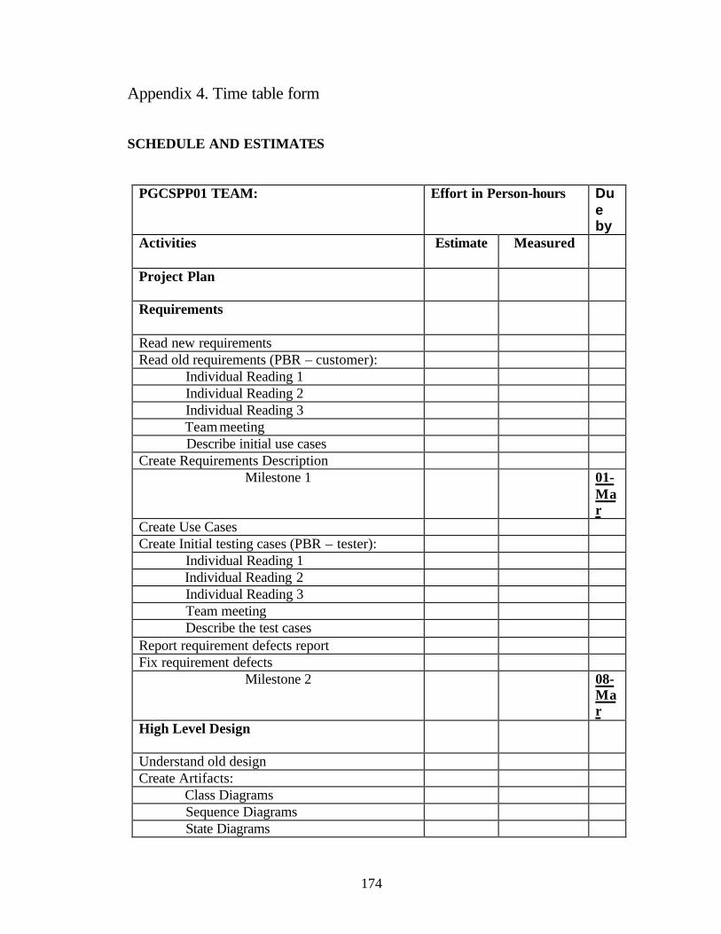
174
Appendix 4. Time table form
SCHEDULE AND ESTIMATES
PGCSPP01 TEAM: Effort in Person-hours Due by
Activities Estimate Measured
Project Plan
Requirements
Read new requirements Read old requirements (PBR – customer): Individual Reading 1 Individual Reading 2 Individual Reading 3 Team meeting Describe initial use cases Create Requirements Description
Milestone 1 01-Mar
Create Use Cases Create Initial testing cases (PBR – tester): Individual Reading 1 Individual Reading 2 Individual Reading 3 Team meeting Describe the test cases Report requirement defects report Fix requirement defects
Milestone 2 08-Mar
High Level Design
Understand old design Create Artifacts: Class Diagrams Sequence Diagrams State Diagrams

175
Class Descriptions Milestone 3.1 29-
Mar
Inspect design for consistency (OORT’s-horizontal):
Individual reading 1 Individual reading 2 Individual reading 3 Fix design defects
Milestone 3.2 05-Apr
Inspect design for traceability (OORT’s – vertical):
Individual reading 1 Individual reading 2 Individual reading 3 Team reading Report the defects Fix design defects Measure the Product
Milestone 4 12-Apr
PGCSPP01 TEAM: 1 Effort in Person-hours Due by
Activities Estimate Measured
Low Level Design
Evolve Artifacts: Class Diagrams Sequence Diagrams State Diagrams Class descriptions Design Software architecture: Package diagrams Deployment Diagrams Measure the Product

176
Milestone 5 03-May
Coding and Testing
Find integration mismatches Create integration mismatches report Create Artifacts: source code for the new parts source code for solving integration mismatches
Execute Unit testing Execute Integration Testing
Create testing plan Create final testing cases Execute test cases Report system-testing results Maintenance
Create Maintenance plan Packaging and delivering
Create delivering plan Milestone 6 10-
May
Package the product Write the simplified User’s Guide Deliver the product
Milestone 7 17-May

177
Appendix 5. Definitions
In this dissertation we use the following terms and definitions:
- Architecture – the definition of the components of a software system and the
interactions (connectors) among them.
- Architectural style – the type of architecture of a software system, e.g., object-
oriented, concurrent, pipe-and-filter, main program and subroutines, etc.
- Architectural changes – an integration strategy that involves changing the
system’s architecture by adding new components and connectors without
changing the architectural style.
- Architectural style changes – an integration strategy that involves changing the
overall system’s architectural style to overcome certain integration problems.
- Baseline architectural style – the architectural style accepted at the design phase
(as the architectural style chosen for the system being developed) based on the
available tools and the programming paradigm for in-house software. This
architectural style can be changed during the COTS architectural style design
activity allowing the integration of COTS products.
- Black-box reuse – reuse of software components, which cannot be modified
because their source code is not available.
- Component – a software or hardware unit that can be part of a larger system.
Software components include procedures, modules, objects, files, etc. Hardware
components are devices with their software drivers.

178
- Conflict – a type of integration problem caused by interactions between one
component (the object of the conflict) and several others; for example,
insufficient memory (the object) for several programs.
- COTS – commercial off-the-shelf. COTS software is obtained from a third party
and used for development of a new software system as a part of it.
- Development environment – environment (platform) used for the system’s
development. It includes compilers, linkers, debuggers and other tools; the
hardware required for successful development can be relevant.
- Environment – software and hardware that interact with the system but are not
part of it. Environment can be development (e.g. compilers, linkers) or target
(e.g. operating system and shared libraries of the deployment platform).
- Evaluation – the part of the reuse process whose goal is to evaluate and select the
best candidates among the COTS products according to the system’s
requirements and other criteria. In this work, evaluation is done primarily from
the perspective of the cost (effort) estimation of integration.
- Glueware – software whose purpose is to facilitate integration of other software,
especially COTS. Glueware can be “put around” a software component to handle
all accesses to it (wrappers) from any other components, or it can be “put
between” several software components to manage their interactions (glue).
Glueware integration strategy uses glueware to overcome interface
incompatibilities.
- Incompatibility – a failure of a software component to interact with the system or
its environment. A classification of the incompatibilities is given in this work.

179
- In-house software – software developed by the organization building the project,
opposite to COTS software obtained from a third party.
- Integration – the part of the reuse process whose goal is to integrate the reused
software into the system overcoming the incompatibilities between them, often
by using glueware. In this work, integration usually means a particular activity
(COTS integration) of the COTS reuse process but sometimes it is used as a
synonym for the whole reuse process.
- Integration problem – a problem the developers face because of an
incompatibility between a software component and other parts of a system or its
environment. Integration problems can be considered as a higher- level
perspective of low-level incompatibilities. The present work introduces five
groups of integration problems: functional, non-functional, architectural style,
architectural, and interface.
- Integration strategy – a set of related techniques intended to overcome a specific
type of integration problems. In this study we use the following integration
strategies: tailoring, modification, re-implementation, architectural style
changes, architectural changes and glueware.
- Non-functional requirements – requirements other than functional, such as
maintainability, usability, portability, etc. However, in this work we treat
separately the requirements for the software environment (e.g., portability),
therefore the non-functional requirements are related only to the user. The
examples of these requirements include usability, performance, reliability,
maintainability, etc.

180
- Objective metric – a metric whose values are obtained using an explicit and
replicable procedure and do not depend on the judgment of the person who
assigned the value to the measurement.
- Re-implementation – an integration strategy in which some functionality
(missing or wrong functionality of COTS products) is re- implemented by the
project developers.
- Subjective metric – a metric whose values involve some human judgment.
- System’s hardware – external hardware directly controlled by the system, for
example on-board devices. It does not include the hardware owned by the target
environment and controlled via system drivers, such as printers, disk drivers, etc.
We shall refer it to as simply hardware.
- Target environment – environment (platform) where the system is supposed to
work. It includes the operating system, other software required for running the
system, the driver-controlled hardware (e.g., disk drivers), and internal computer
hardware (e.g., CPU, memory, etc.).
- White-box reuse – reuse of software components that allows for their
modification.

181
REFERENCES [Abd-Allah, Boehm 96] Abd-Allah, A., Boehm, B.W., “Models for Composing Heterogeneous Software Architectures”, USC Technical Report, USC/CSE-96-505, August 1996. [Abts et al. 00] Abts, C., Boehm, B.W., Clark, E.B., “COCOTS: A Software Integration Lifecycle Cost Model – Model Overview and Preliminary Data Collection Findings”, Proceedings ESCOM-SCOPE 2000 Conference, 2000. [Albrechtsen 92] Albrechtsen, H., “Software information systems: information retrieval techniques” in “Software reuse and reverse engineering in practice”. Edited by P.A.V. Hall, Chapman and Hall, 1992, pp. 99 –127. [Baker 97] Baker, S., "CORBA distributed objects using Orbix", Addison-Wesley, 1997. [Balk, Kedia 00] Balk, L.D., Kedia, A., “PPT: A COTS Integration Case Study”, Proceedings of the 22nd International Conference on Software Engineering, Limerick, Ireland, 2000, pp. 42-49. [Basili 92] Basili, V., “Applying the Goal/Question/Metric Paradigm in the Experience Factory”, Technical report, University of Maryland, 1992. [Basili, Rombach 91] Basili, V., Rombach, H., "Support for comprehensive reuse", Software Engineering Journal, September 1991, pp. 303-316. [Boehm and Abts 99] Boehm, B., Abts, C., "COTS Integration: Plug and Pray?", IEEE Computer, January 1999, pp. 135-138. [Boland et al. 97] Boland, D., Coon, R., Byers, K., Levitt, D., "Calibration of a COTS Integration Model Using Local Project Data", The Twenty-second Software Engineering Workshop, NASA/Goddard Space Flight Center Software Engineering Laboratory (SEL), Greenbelt, MD, December 1997, pp. 81-98. [Box 98] Box, D., "Essential COM", Addison-Wesley, 1998. [Breslin 86] Breslin, J., "Selecting and Installing Software Packages. New Methodology for Corporate Implementation", 1986, Greenwood Press. [Brownsword et al. 98] Brownsword, L., Carney, D., Oberndorf, T., "The Opportunities and Complexities of Applying Commercial-Off-the-Shelf Components", 1998, Available WWW <URL:http://interactive.sei.cmu.edu/Features/1998/June/Applying_COTS/Applying_COTS.htm> (1998).

182
[Brownsword, Oberndorf 98] Brownsword, L., Oberndorf, P., “Are you ready for COTS?”, CTS98, 1998 [Brownsword et al. 00] Brownsword, L., Oberndorf, T., Sledge, C.A., “Developing New Processes for COTS-Based Systems”, IEEE Software July/August 2000, pp. 48-55. [Carney, Long 00] Carney, D., Long, F., “What Do You Mean by COTS?”, IEEE Software, March/April 2000, pp. 83-86. [Carney, Oberndorf 97] Carney, D.J., Oberndorf, P.A., "The Commandments of COTS: Still in Search of the Promised Land", Crosstalk, May 1997, Vol.10, No.5, pp 25-30. [Connell, Shafer 87] Connell, J.L., Shafer, L., "The Professional User's Guide to Acquiring Software", 1987, Van Nostrand Reinhold Company. [Crnkovic, Larsson 00] Crnkovic, I., Larsson, M., “A Case Study: Demands on Component-based Development”, Proceedings of the 22nd International Conference on Software Engineering, Limerick, Ireland, 2000, pp. 23-31. [Dargan 95] Dargan, P.A., "Building Open Systems with COTS Products: Successes and Challenges", Open Systems Standards Tracking Report, Volume 4, Number 3, November 1995, Available WWW <URL:http://www.digital.com/info/osstr/tr1195.htm> (1998). [Dashofy et al. 99] Dashofy, E., Medvidovic, N., Taylor, R.N., “Using Off-The-Shelf Middleware to Implement Connectors in Distributed Software Architectures”, Proceedings of the 21st International Conference on Software Engineering, Los Angeles, USA, 1999, pp. 3 – 12. [Davis, Williams 97] Davis, M.J., Williams, R.B., Software Architecture Characterization, Proceedings of the 1997 Symposium on Software Reusability (SSR'97), Boston, USA, May, 1997, pp. 30-38. [Dong et al. 99] Dong, J., Alencar, P.S.C., Cowan, D.D., “A Component Specification Template for COTS-based Software Development”, Proceedings of the First Workshop on Ensuring Successful COTS Development, Los Angeles, USA, 1999. [Fox et al. 97] Fox, G., Lantner, K., Marcom, S., "A Software Development Process for COTS-based Information System Infrastructure", The Twenty-second Software Engineering Workshop, NASA/Goddard Space Flight Center Software Engineering Laboratory (SEL), Greenbelt, MD, December 1997, pp. 133-153.

183
[Fox et al. 98] Fox, G., Marcom, S., Lantner, K., "A Software Development Process for COTS-based Information System Infrastructure. Part II: Lessons Learned", Crosstalk, April 1998, Available WWW <http://www.stsc.hill.af.mil/CrossTalk/1998/apr/process.asp> [Gacek 97] Gacek, C., “Detecting Architectural Mismatches During Systems Composition”, USC Technical report, USC/CSE-97-TR-506, July 1997. [Garlan et al. 95] Garlan, D., Allen, R., Ockerbloom, J., “Architectural Mismatch or Why it's hard to build systems out of existing parts”, Proceedings of the 1995 International Conference on Software Engineering, Seattle, WA, USA, 1995, pp. 179-185. [Gentleman 97] Gentleman, W.M., "Effective Use of COTS (Commercial-Off-the-Shelf) Software Components in Long Lived Systems", The Proceedings of ICSE 97, Boston, USA, 1997, pp. 635-636. [Giguere 97] Giguere, E., "Java Beans and the New Event Model", Dr.Dobbs's Journal, April 1997, pp. 50-53. [Girardi, Ibrahim 94] Girardi, M.R., Ibrahim, B., “Automatic Indexing of Software Artifacts”, The Proceedings of the Third International Conference on Software Reuse, 1994, Rio de Janeiro, Brazil, pp. 24 – 32. [Haynes et al. 97] Haynes, G., Carney, D., Foreman, J., "Component-Based Software Development / COTS Integration", 1997, Available WWW <URL:http://wei.sei.cmu.edu/str/descriptions/cbsd.html> [Hissam, Carney 99] Hissam, S.A., Carney, D., “Isolating Faults in Complex COTS-based Systems”, Journal of software maintenance: research and practice, 11, 1999, pp. 183-199. [Hybertson et al. 97] Hybertson, D.W., Ta, A.D., Thomas W.M., "Maintenance of COTS-intensive Software Systems", Software Maintenance: Research and Practice, July-August 1997, Vol.9, No.4, pp.203-216. [Jeng, Cheng 95] Jeng, J.J., Cheng, B.H.C., “Specification Matching for Software Reuse: A Foundation”, Proceedings of Symposium on Software Reuse SSR’95, Seattle, WA, USA, 1995, pp. 97 – 105. [Kontio 95] Kontio, J., "OTSO: A Systematic Process for Reusable Software Component Selection", University of Maryland, technical report, December 1995. [Kunda, Brooks 99] Kunda, D., Brooks, L., “Case Study: Identifying factors that support COTS component selection”, Proceedings of the First Workshop on Ensuring Successful COTS Development, Los Angeles, USA, 1999.

184
[Lindqvist, Jonsson 98] Lindqvist, U., Jonsson, E., "A Map of Security Risks Associated with Using COTS", Computer, June 1998, pp. 60-66. [Maiden et al. 97] Maiden, N.A.M., Ncube, C., Moore, A., "Lessons Learned During Requirements Acquisition for COTS Systems", CACM, December 1997, Vol.40, No.12, pp. 21-25. [Maiden et al. 99] Maiden, N.A.M., James, L., Ncube, C., “Evaluating Large COTS Software Packages: Why Requirements and Use Cases are Important”, Proceedings of the First Workshop on Ensuring Successful COTS Development, Los Angeles, USA, 1999. [Medvidovic et al. 97] Medvidovic, N., Oreizy, P., Taylor, R.N., Reuse of Off-the-Shelf Components in C2-Style Architectures, Proceedings of the 1997 Symposium on Software Reusability (SSR'97), Boston, USA, May, 1997, pp. 190-198. [Meyer 99] Meyer, B., "On to Components", IEEE Computer, January 1999, pp.139-140. [McDermid, Talbert, 97] McDermid, J., Talbert, N., "The Cost of COTS" (interview), Computer, June 1997, pp. 46-52. [Morisio et al. 00] Morisio, M., Seaman, C.B., Parra, A.T., Basili, V.R., Kraft, S.E., Condon, S.E., “Investigating and Improving a COTS-Based Software Development Process”, Proceedings of the 22nd International Conference on Software Engineering, Limerick, Ireland, 2000, pp. 32-41. [Nay 99] Nay, D.R., “COTS Integration Planning”, Proceedings of the First Workshop on Ensuring Successful COTS Development, Los Angeles, USA, 1999. [Neighbors 94] Neighbors, J.M., An Assessment of Reuse Technology after Ten Years, Proceedings of the Third International Conference on Software Reuse: Advances in Software Reusability, Rio de Janeiro, Brazil, November, 1994, pp. 6-13. [Oberndorf 97] Oberndorf, T., "COTS and Open Systems - An Overview", 1997, Available WWW <URL:http://wei.sei.cmu.edu/str/descriptions/cots.html#ndi> [Ousterhout 98] Ousterhout, J., "Scripting: Higher-Level Programming for the 21st Century", IEEE Computer, March 1998, pp. 23-30. [Parra et al. 97] Parra, A., Seaman, C., Basili, V., Kraft, S., Condon, S., Burke, S., Yakimovich, D., The Package-Based Development Process in the Flight Dynamics Division, The Twenty-second Software Engineering Workshop, NASA/Goddard Space Flight Center Software Engineering Laboratory (SEL), Greenbelt, MD, December 1997, pp. 21-56.

185
[Payton et al. 99] Payton, J., Keshav, R., Gamble, R.F., “System Development Using the Integrating Component Architecture Process”, Proceedings of the First Workshop on Ensuring Successful COTS Development, Los Angeles, USA, 1999. [Polen et al. 99] Polen, S., Rose, L., Phillips, B., “Component Evaluation Process”, 1999. [Rowe 97] Rowe, R., "Building a Smart Online Video Application", Dr.Dobb's Journal, December 1997, pp. 78-84. [Seacord 00] Seacord, R.C., “Case Study: Global Combat Support System – Air Force”, Available at WWW <URL:http://www.sei.cmu.edu/cbs/cbse2000/papers/10/10.html> [Simons, Jamison 96] Simons, J.M., Jamison, D.E., "Operational and Development Cost Modeling of NASA's Earth Observing System and Data Information System (EOSDIS)", SpaceOps 96, Munich, Germany, September 1996, Available WWW <URL:http://www.op.dlr.de/SpaceOps/spops96/simmod/sm-5-09/5_09.htm> [Shaw, Clements 97] Shaw, M., Clements, P., “A Field Guide to Boxology: Preliminary classification of Architectural Styles for Software Systems”, Proceedings COMPSAC97, 21st Int’l Computer Software and Application Conference, August 1997, pp. 6-13. [Shaw, Garlan 96] Shaw, M., Garlan, D., "Software Architecture. Perspectives on an Emerging Discipline", 1996, Prentice Hall, Upper Saddle River, NJ. [Shaw 95] Shaw, M., Architectural Issues in Software Reuse: It's Not Just the Functionality, It's Packaging, Proceedings of the Symposium on Software Reusability, 1995, Seattle, WA, USA, pp. 3-6. [Schneidewind 99] Schneidewind, N.F., “Issues and Methods for Assessing COTS Reliability, Maintainability, and Availability”, Proceedings of the First Workshop on Ensuring Successful COTS Development, Los Angeles, USA, 1999. [Smith et al. 97] Smith, R., Parrish, A., Hale, J., "Component Based Software Development: Parameters Influencing Cost Estimation", Twenty-second Software Engineering Workshop, NASA/Goddard Space Flight Center Software Engineering Laboratory (SEL), Greenbelt, MD, December 1997, pp. 283-301. [Sparks et al. 96] Sparks, S., Benner, K., Faris, C., "Managing Object-Oriented Framework Reuse", IEEE Computer, September 1996, pp. 52-61. [Swanson, MacMagnus 97] Swanson, B.D., MacMagnus, J.G., "C++ Component Integration Obstacles", Crosstalk, May 1997, Vol.10, No.5, pp. 22-24.

186
[Thompson 96] Thompson, T., “Must-See 3-D Engines”, Byte, June 1996, pp. 137-144. [Vidger, Dean 97] Vidger, M.R., Dean, J., "An Architectural Approach to Building Systems from COTS Software Components", The Twenty-second Software Engineering Workshop, NASA/Goddard Space Flight Center Software Engineering Laboratory (SEL), Greenbelt, MD, December 1997, pp. 99-131. [Vidger et al. 98] Vidger, M.R., Gentleman, W.M., Dean. J., "COTS Software Integration: State of the art", Available WWW <URL:http://wwwsel.iit.nrc.ca/abstracts/NRC39198.abs> (1998). [Voas 98a] Voas, J.M., "The Challenges of Using COTS Software in Component-Based Development", Computer, June 1998, pp. 44-45. [Voas 98b] Voas, J.M., "Certifying Off-the-Shelf Software Components", Computer, June 1998, pp. 53-59. [Wallnau et al. 98] Wallnau, K.C., Carney, D., Pollak, B., "How COTS Software Affects the Design of COTS-Intensive Systems". Available WWW <URL:http://interactive.sei.cmu.edu/Features/1998/June/COTS_Evaluation/COTS_Evaluation.htm> (1998). [Workshop 89] Proceedings of the Software Re-use Workshop, Utrecht, the Netherlands, November, 1989. [Yakimovich et al. 99] Yakimovich, D., Bieman, J.M., Basili, V.R., “Software architecture classification for estimating the cost of COTS integration”, Proceedings of the 21st International Conference on Software Engineering, Los Angeles, USA, 1999, pp. 296 –302. [Yakimovich et al. 99b] Yakimovich, D., Travassos, G.H., Basili, V.R., "A Classification of Software Components Incompatibilities for COTS Integration" Software Engineering Laboratory Workshop, 1999. [Zhong, Edwards 98] Zhong, Q., Edwards, N., "Security Control for COTS Components", Computer, June 1998, pp. 67-73.