ABSTRACT - MATE ROV Competition
23
Transcript of ABSTRACT - MATE ROV Competition


URI HYDROBOTICS TECHNICAL REPORT 2018
2
ABSTRACT
Our goal this year was to facilitate the building of a learning
community. It is our hope that this new approach to team dynamics
helps generate a close-knit group built to last. ROVs are not built in
a day. Behind every ROV is a story of serious dedication to a
seemingly endless task. Only the few who hold their ground and stick
it out to the very end understand the feeling of accomplishment from
that success. ICARUS is a tribute to those who keep their distance
from the sun.
Figure 1: International Competition Team with ROV ICARUS

URI HYDROBOTICS TECHNICAL REPORT 2018
3
TABLE OF CONTENTS
ABSTRACT-------------------------------------------------------------------2
INTRODUCTION--------------------------------------------------------------4
DESIGN RATIONALE-----------------------------------------------------------4
ELECTRONIC SYSTEM----------------------------------------------------4
1. POWER DISTRIBUTION---------------------------------------5
2. CONTROL STACK------------------------------------------- 6
3. TETHER----------------------------------------------------6
4. CAMERA---------------------------------------------------7
5. TOPSIDE---------------------------------------------------7
6. SOFTWARE-------------------------------------------------8
1. WIFI-------------------------------------------------9
2. MAPPING--------------------------------------------9
MECHANICAL SYSTEM--------------------------------------------------10
1. FRAME--------------------------------------------------- 11
2. PROPULSION----------------------------------------------11
3. MANIPULATION------------------------------------------- 13
4. BUOYANCY----------------------------------------------- 15
SAFETY PROTOCOL---------------------------------------------------------- 16
1. ROV OPERATION------------------------------------------ 16
2. SHOP BEHAVIOR-------------------------------------------16
3. SAFETY FEATURES ON VEHICLE------------------------------ 17
COMPANY------------------------------------------------------------------18
RESULTS/REFLECTION--------------------------------------------------------21
ACKNOWLEDGEMENTS ------------------------------------------------------ 21
REFERENCES---------------------------------------------------------------- 22
APPENDICES---------------------------------------------------------------- 22
1. GANTT CHART-------------------------------------------- 22
2. BUDGET--------------------------------------------------23

URI HYDROBOTICS TECHNICAL REPORT 2018
4
INTRODUCTION URI Hydrobotics is comprised of ambitious undergraduate students that strive to design,
manufacture and build an explorer class ROV to compete in the MATE competition. As a company
we strive to not only compete but also educate any new members to expand their knowledge and
understanding of robotics systems. Every year poses new challenges and learning opportunities even
for the most experienced veterans on the team, this allows everyone to further their own knowledge
as well as to help one another learn in the process. We as a company project an atmosphere that
allows any major to come and learn and put the time they want into educating themselves. We have
a dedicated team of upperclassmen that work to keep the team in a functioning order and help
direct students' endeavors. This year, we bring ROV ICARUS to Seattle, Washington.
DESIGN RATIONALE
ELECTRONIC SYSTEM
As the main goal of Hydrobotics is to teach, most design decisions are based solely with the intention
to teach and learn by doing. In that light we spent a considerable amount of this year teaching
important skills such as soldering, electronics, PCB fabrication and software. With the completion of
the robot we certify that all those present for development have a well-rounded understanding of
every component in action and how it was implemented.
Figure 1: ICARUS SID

URI HYDROBOTICS TECHNICAL REPORT 2018
5
POWER DISTRIBUTION
To correctly power all of the subsystems on ICARUS, several different voltages were necessary. A
12V converter and two 5V converters were used to achieve power distribution. The 12V output is
necessary for the operation of the ESCs and the T100 motors. The 5V output is necessary for the
manipulator DC motor, the compute module power, the various sensors, and the servos. GPIO pins
aboard the compute module provide power to the H-bridge circuit that controls the orientation of
the rotations of the manipulator’s DC motor. Also, a USB hub that is connected to the compute
module acts as power for the Maestro and other peripheral devices.
CUSTOM POWER DISTRIBUTION BOARD
To conserve space within the bottle and promote efficiency, URI Hydrobotics has developed a PCB
that consolidates all of the necessary power distribution. With safety also kept in mind, it was
designed in a way such that the 48V input from the tether is separated from the output voltages.
Opposite the input power, there are two connectors that output 12V. Two different 5V converters
are used. One is solely for the power of the compute module. The other 5V converter is for all
other auxiliary 5V power needs.
Figure 2: Labeled Power Distribution Board

URI HYDROBOTICS TECHNICAL REPORT 2018
6
CONTROL STACK
An in-house circuit board containing all other necessary wiring for the sensors, wifi module, and h-
bridge is used to further promote efficiency and conserve space within the bottle. This board is
connected to the compute module in a way such that the PCB rests directly above the compute
module.
Figure 3: Pi-hat PCB
TETHER
The tether is an off the shelf Igus CF-211.010 chainflex cable of 15 meters in length. This cable was
donated to us via the Igus YES program targeted at academic projects. The CF-211.010 is a
continuous flex cable comprised of four 23 gauge twisted pairs for ethernet and two 17-gauge
wires to deliver 48VDC to the robot. In this application, due to limited space in our bottle

URI HYDROBOTICS TECHNICAL REPORT 2018
7
penetrators, we opt to use only two twisted pairs to send T100 ethernet, plenty of bandwidth to
pass all data necessary for operation.
Figure 4: CF-211.101 Implementation
CAMERA
2 Raspberry Pi V2.1 Cameras are utilized by ICARUS. Both are connected directly to the Raspberry
Pi 3 Compute Module. Looking at Figure X, the cameras are oriented in a way such that CAM1
focuses on the area underneath the bottle where most of the manipulation of objects will be taking
place and is also the camera that is utilized by the video recognition software for identifying the
plane wings. CAM0 provides a more general view of what is in the front of ICARUS. CAM0 can also
show the manipulator when it is positioned completely horizontally, which can prove useful for
some tasks such as connecting the ADV.
Figure 5: Orientation of Pi Cameras
TOPSIDE
The topside control system is comprised of an Intense PC recycled from URI Hydrobotic’s 2016
MU-ROV that is running Debian and communicates with ICARUS through Ethernet via a Gigabit
Ethernet Network Switch. The control system resides within a pelican case, where a 21” Ultrawide
Monitor is mounted into the top of the case and serves as the main monitor, where most, if not all,
software processes occur. The topside control system is also designed to allow for peripherals

URI HYDROBOTICS TECHNICAL REPORT 2018
8
(such as a second monitor, USB connections, ethernet connections) to be connected to the system
through the various pass throughs on the control panel. To supply power to both the electronics
underneath the control panel and peripherals above the control panel, a server rack-mounted
surge protector is used.
Figure 6: Topside Control System
SOFTWARE
The overall software architecture that comprises URI Hydrobotics’ robot is an extension of the
software architecture that was developed for the company’s 2016 MU-ROV. The same method of
using lightweight communications and marshalling(LCM) and a system link called Procman to
communicate between topside and ICARUS. Many changes were made, however, to the pre-
existing scripts such as the mapping of the motor and servo motions to the Xbox 360 Controller
and implementing video streams for two cameras from the same compute module. New scripts
were developed to complete the video recognition and the WIFI communications, as well as
reading sensor data and determining the rotation of the manipulator arm.

URI HYDROBOTICS TECHNICAL REPORT 2018
9
VIDEO RECOGNITION
See Separate Image Recognition Document
WIFI
ICARUS uses WIFI communications not only for connecting to the OBS, but also uses WIFI
communications for the release of the lift bag. For the release of the lift bag, an ESP-12V
microcontroller is used to create an access point and a web page, similar to the OBS. A python
script is then used to send serial AT commands from ICARUS and scrapes the web page that the
ESP-12V hosts. When the web page is accessed, the solenoid holding the lift bag in place will then
release.
MAPPING
Modifications have been made to the Hydrobotics’ 2016 MU-ROV control mapping software to
suit the needs of all electrical components for ICARUS. Additions were made to accommodate the
motion of two different sets of servos. An executive decision was made to control the rotation of
the DC motor manually through a script rather than to map it on the Xbox 360 Controller, to avoid
accidentally rotating the motor by pressing a button.
URI HYDROBOTICS TECHNICAL REPORT 2018
10
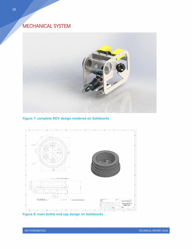
MECHANICAL SYSTEM
Figure 7: complete ROV design rendered on Solidworks
Figure 8: main bottle end cap design on Solidworks

URI HYDROBOTICS TECHNICAL REPORT 2018
11
FRAME
The frame for ICARUS is composed mostly of High Density Polyethylene. Considerations were in
mind to keep this design as lightweight and sturdy as possible looking back at structural damage
and warping of the Hydrobotics 2017 ROV for inspiration. The Frame design is composed of 2 hull
panels and 4 lateral HDPE cross bars. The frame was laser cut from a ½ inch sheet of HDPE to
provide 2 hull panels thick enough to not warp and to provide the manufacturing quality we
couldn’t otherwise provide. The 4 lateral cross bars were placed to prevent racking and torsion in
the frame when the ROV is in use. Each lateral support was also placed in a key location to serve
purposes for mounting necessary features. This included the mounting for the main manipulator,
mounting for ballast, mounting for the vertical and lateral thrusters close to the center of mass, and
in the rear mounting for a steel eye-ring used for tether stress relief.
Perhaps the most cautiously approached piece of the frame design was the bottle and end-cap as
it would provide housing for all the electronics stack and would be catastrophic if this system were
to fail. As well as housing the electronics the bottle would provide mounting for both Raspberry Pi
cams used for observing the ROV’s environment. To do this an acrylic mounting plate would hold
the electronics centered in the bottle mounted on two discs 3D printed to match the inner
diameter of the acrylic bottle. This in turn also made the system easy to service as the endcap
could be removed and the electronics could slide out on an easy to access mounting board. Using
the Parker Handbook for O-ring sizing and a dual O-ring design the mechanical team created a
technical design to match (seen in figure 1B). It was decided this piece was to be manufactured out
of PVC by a machinist based locally off the University of Rhode Island campus. This was to provide
the specifications necessary for the seal to function properly which could not be provided by our
team’s equipment capabilities while also cutting down on lead shipping time.
PROPULSION
For propulsion on the ICARUS, movement was provided by 4 Blue Robotics T100 Thrusters. T100
thrusters were chosen because of the excellent reliability of Blue Robotics products as well as the
lower cost from previously purchased thrusters while still meeting necessary power requirements.
Finger guards complying with safety standards IP20 were also manufactured for the 4 thrusters
using premade 3D printed designs from thingiverse from a user name piercet.

URI HYDROBOTICS TECHNICAL REPORT 2018
12
The ROV has 4 practical degrees of freedom, 3 of which are linear; heave is provided by the single
vertical thruster, sway is provided by the single central lateral thruster, and surge is provided by
both side mounted forward thrusters. Also, a fourth practical degree of yaw is controlled by firing
the two forward thrusters in opposite directions. In order to keep the ROV stable when strafing,
elevating, or descending, the lateral and vertical thrusters were mounted as close to a point
between center of buoyancy and mass as possible.
Figure 9: Main Manipulator Arm Location/Orientation
Figure 10: half section of manipulator design showing inner workings
The dynamic arm was designed with the mindset that it would need 3 effective axes of
motions to complete the challenges proposed by tasks 2 and 3. These tasks would require an arm
that could grasp variable circumference pieces of PVC, move objects on the ground to an upward
position, and rotate objects positioned directly below the ROV continuously in 360 degrees of
motion. These skills were essential for manipulating all manner of PVC, deploying the hydropower
station task 3, and leveling the OBS for task 2.
In order to provide 90-degree pitch from a vertical downward position to a level horizontal
position, the entire arm would be mounted on an aluminum c-bracket dual mounted to 2 servo

URI HYDROBOTICS TECHNICAL REPORT 2018
13
motors (See Figure 2B for orientation of dynamic arm mount). For continuous rotation to level the
OBS, a DC motor with a special gear mounted on an axle would rotate around the outer half of the
manipulator along another fixed specially laser cut gear (See figure 2A for half section of
manipulator). To prevent an electrical connection breaking during rotation, a special IP68 rated slip
ring would host the electrical connection between the manipulators rotor and stator sections. The
grasper on the manipulator was specially designed with 2 channels for ½ and 2-inch PVC and
would be actuated by a 3rd servo motor. A majority of framing on the manipulator will be made of
Delrin because it is low friction and easily machinable and 2 Delrin sleeves will have to be rotated
about each other.
MANIPULATION (LIFT BAG SYSTEMS)
Figure 11: lift bag release device
Figure 12: lift bag (designed for 25lb
payload)

URI HYDROBOTICS TECHNICAL REPORT 2018
14
Figure 13: electronics and solenoid for remote release
Lift bags were a challenging part of the manipulation package as they would have to be
precisely guided around the several U-bolts for the package to deploy. The lift bag package was
designed to be reloaded after removing the debris. The lift bags are housed in a tube that protrudes
from the front of the frame, in the cone of vision of the Raspberry Pi cameras. The navigator and
pilot would need to slowly guide a carabiner around both U-bolts one after the other, which then
the ROV would pull back, releasing the electronics package from the tube (Figure 13). The lift bag
(Figure 12) will be deployed with attached buoyancy foam in order to right itself, where the ROV will
hold stable as air from a static jig fills the lift bag from below (Air will be routed down with the tether
and through a static jig seen in the bottom right of figure 2B).
The electronics package will receive a WIFI signal to release the lift bag from the debris
package once the debris have been moved from the engine. This would happen when a
transmitter on the side of the bottle came within approximately 10cm which would actuate a
solenoid releasing the carabiner holding the lift bag to the object. The chute would also be reused
later to hold the ADV and mount it on the mooring chain which would need to be navigated
similarly to how the lift bag packages would need to be deployed.

URI HYDROBOTICS TECHNICAL REPORT 2018
15
BUOYANCY
Figure 14: trim table created using common mass properties and volumes of materials on the
ROV provided by Solidworks
For calculations of buoyancy for the ICARUS, mass properties where heavily used from
Solidworks 2017 to estimate where the center of mass and center of buoyancy were (shown in
figure 4A). Here we wanted to have the center of buoyancy and center of mass directly above each
other but as far away as we could have in order to increase the bot’s stability. Solidworks gave
relative XYZ coordinates which could be used to relate center and mass and center of buoyancy on
the ICARUS frame and allowed us to center them towards the front of the frame. This is where the
issue of the sideways acrylic bottle housing came into play; it added a large positive buoyant force
to the front of the ROV and large weight to one side of the ROV because of the PVC end cap. Blue
Robotics Subsea Buoyancy Foam R-3312 was used to move some buoyant force to the back of the
bot (see figure 1A), then variable size pig iron housed in PVC pipe was used to ballast the ROV
toward the front and off from the center due to the end cap. The trim table could only get us a
close estimate to how the ROV would need ballast to be slightly positively buoyant (this is so if the
ROV failed while in use it would slowly return to the surface of the water for retrieval: See figure 4A
for acceleration upward data). The final trimming of the ROV ballast was compensated for when
the ROV was tested in water for the first time.

URI HYDROBOTICS TECHNICAL REPORT 2018
16
SAFETY
Students’ safety paramount to create a constructive work environment. As policy, we ensure all
members adhere to safety protocols. Leaders equip new members with the necessary safety
measures when working with power tools and electronic devices to prevent accidents before they
happen.
ROV OPERATION
Here at URI Hydrobotics we have established key safety protocols when deploying and testing the
ROV and all its systems. Before testing in water, the ROV is placed on the ground with all members
standing a safe distance away. Then power is applied to the ROV and all thrusters are tested. Once
the ROV is deemed safe to deploy, pilots take their hands off the controls and two members of the
crew lower the ROV and tether into the water. The drivers are not allowed to touch any driving
instrumentation until an all good signal is communicated from the crew lowering the ROV into the
pool. Once the ROV has completed its mission it then returns to the surface where it is then
received by the two members that lowered the ROV into the water previously. Like its deployment,
when the ROV is being recaptured both drivers must put down any driving instruments and allow
the pool side members to receive the robot. The ROV is then systematically powered down and a
routine visual inspection of the robot is conducted to look for any visual damage or other
abnormalities.
SHOP BEHAVIOR
During the inception of this year's team the prior members along with mentors give all the new
students a safety rundown that gives members the necessary safety procedures that are needed to
work in the shop environment. Once the mentors cleared the new members they are given access
to the keycard locked lab to work. Once in the lab all company members are required to dawn the
correct PPE (personal protective equipment), when working with plastic and heat or anything that
produces a lot of dust a mask is required to be working to prevent inhalation of the particulates. In
the lab members are required to work with the buddy system to prevent any manufacturing issues
that may occur, but also to have each member peer to peer check one another with safety
procedures. In the event of an emergency the buddy system allows for the injured member to
immediately be cared for and given immediate attention, it also provides a speedy response time
because one party can call for help as the situation occurs if it could not be prevented. Perhaps the
biggest shop safety procedure that we as a company go through is the secured power system into
the shop. After access is gained using the key card access a mentor must come to the shop and
power the shop using a key which only mentors can obtain. This allows the mentors to log shop
operation to keep a concise ledger of events during the shop hours.

URI HYDROBOTICS TECHNICAL REPORT 2018
17
Figure 15: Proper PPE being used in the work environment
ROBOT SAFETY FEATURES
Figure 16: 3D Printed ROV thruster guards
Safety was the key feature when designing all the static and dynamic parts of ICARUS throughout
its evolution. The mechanical team developed a structure absent of sharp corners and edges to
prevent cutting or snagging, but also protects cables from being severed in the underwater
environment; the department achieved this through rigorous deburring of all edges that were not
machined with a bevel on ICARUS. The frame is also outfitted with a carry handle for the ease of
transport and deployment, this allows the ROV to be handled in a safe and secure way when in

URI HYDROBOTICS TECHNICAL REPORT 2018
18
transit. Also fitted onto the 4 thrusters are safety approved guards to prevent any injury that would
occur if a finger were to become lodged into the thruster system. The robot also has approved
tether security on both the ROV and topside control to provide stress relief for the tether. This
allows for the strain of the tether to be relieved into the ROV and the topside control box to
prevent tearing in the tether and allowing exposed wire into the water environment. Along with
tether security the electronics team implemented a 15A fuse was attached to the tether that will
sever power to the ROV from the main power supply in the event of a power spike or overheating.
Inside the bottle of the ROV there are two temperature sensors that monitor the ambient
temperature of the electronic systems to prevent overheating, in the event of an overheating
incident the robot is shut down and returned to the surface using the innate positive buoyancy the
ROV possesses.
COMPANY
The goal of the Hydrobotics team is to share experiences encompassing a variety of engineering
and life skills. To encourage active participation this year, we proposed a new system to distribute
funding and resources that rewards those who rise to the challenge. Every participant is capable of
becoming a leader. In order to streamline the process of research and development we
encouraged all work/projects for the ROV to be completed in a group setting. To disperse our
limited resources, we established a standardized project proposal (P2) form to field ideas and
promote collaboration. The P2 form is designed to aid the sharing of ideas, certifying that
participants have put in the necessary thought and research for project completion. This form is
not only good for basic documentation but also allows individuals to take ownership of their
respective project only having to answer to the leaders of the club. A standard project proposal, at
its core, is a free standing written document that could be consumed and understood without any
prior knowledge of the system it outlines. Once the proposal is completed it is presented to the
board for approval.
The board will consist of four experienced members (President, CFO, CTO, CIO, COO) , all with
previous success on team projects, and one faculty advisor or graduate mentor. This board hears
all project proposals before every weekly meeting and decides on funding/support accordingly.
This allows for any participant to propose a unique idea, gain experience presenting technical
subjects, and be rewarded with the opportunity to bring that goal to completion. The proposal
writer is by default the project lead and is responsible for organizing, mentoring, and completing
projects as a team.

URI HYDROBOTICS TECHNICAL REPORT 2018
19
Hydrobotics has received funding from long standing relationships with Raytheon and
team members’ supporting colleges as well as a tether donation from Igus. We are actively
engaged in our school’s engineering program’s outreach events to boost enrollment in URI
engineering. Active mentorship is the cornerstone of Hydrobotics outreach as our goal is to spread
and expand on skills and knowledge attained in the engineering curriculum. ICARUS is the
culmination of a year’s long effort to educate and empower engineering students to push beyond
their horizons and demonstrate their expertise.
Jordan Beason - CTO - Auxiliary Pilot
2nd Year Electrical Engineering and Chinese Language
Cole Boulanger - CIO - Co-Pilot
4th Year Computer Engineering

URI HYDROBOTICS TECHNICAL REPORT 2018
20
Hunter Claudio - COO - Tether Management
2nd Year Mechanical Engineering and German Language
Jackson Sugar - President – Pilot
5th Year Ocean Engineering and Chinese Language
Austin Clark - CFO - Pump Operator
2nd Year Mechanical Engineering and German Language

URI HYDROBOTICS TECHNICAL REPORT 2018
21
RESULTS/REFLECTION
This season provided a significant turning point for URI Hydrobotics. After a failed
qualification attempt for the 2017 MATE Competition, mentors and captains alike took a large step
back to discuss the true goals of the team, our motives, and what needs to happen in the future to
be successful. The new season came with many challenges, on an intrapersonal and technological
level. Only through teamwork, long hours, and a sense of responsibility between all members were
we able to develop ICARUS to its full potential. The focus of our team is to educate; however, a time
always comes every season where results are expected. It’s during these times; the late team
meetings, the all-nighters, and daily test sessions, that engineering and collaboration in its most
perfect form occurs. It’s during these times that students learn more about themselves, their
capabilities, and their confidence as future engineers within society. During these times, the true goal
of Hydrobotics is realized, and students learn just what it takes to be an engineer. ICARUS was built
off these principles and will continue to be improved upon over the coming years as we improve our
leadership and recruiting strategy.
ACKNOWLEDGEMENTS
Hydrobotics would like to extend their gratitude to these people and organizations that have made
contributions and supported the team throughout the design process:
Robin Freeland, Dr. Brennan Phillips and Dr. Stephen Licht - our academic advisors, who
provided insight during the design process
Gail Paolino- For performing all Hydrobotics purchasing
MATE Center- For organizing the competition, and providing a wonderful platform for education
Raytheon - For contributing monetary support
URI College of Engineering - For contributing monetary support
URI College of Ocean Engineering - For contributing monetary support
IGUS- For providing the tether for ICARUS

URI HYDROBOTICS TECHNICAL REPORT 2018
22
REFERENCES
Adafruit, Driver for TI's ADS1015, 2016, GitHub Repository,
https://github.com/adafruit/Adafruit_ADS1X15
Adafruit, Driver for Adafruit's LSM303DLHC breakout, 2016, GitHub Repository,
https://github.com/adafruit/Adafruit_LSM303
Piercet, Intake Guards for Blue Robotics T100 and T200 ROV Thrusters
, 2016, https://www.thingiverse.com/thing:1498338
APPENDIX
GANTT CHART

URI HYDROBOTICS TECHNICAL REPORT 2018
23
BUDGET