ABSTRACT - fileABSTRACT Carbon nanotubes (CNTs) are a recently discovered allotrope of carbon. ......
36
CARBON NANOTUBES 2010/2011 ABSTRACT Carbon nanotubes (CNTs) are a recently discovered allotrope of carbon. They take the form of cylindrical carbon molecules and have novel properties that make them potentially useful in a wide variety of applications in nanotechnology, electronics, optics, and other fields of materials science. They exhibit extraordinary strength and unique electrical properties, and are efficient conductors of heat. Inorganic nanotubes have also been synthesized. A nanotube is a member of the fullerene structural family, which also includes buckyballs. Whereas buckyballs are spherical in shape, a nanotube is cylindrical, with at least one end typically capped with a hemisphere of the buckyball structure. Their name is derived from their size, since the diameter of a nanotube is of the order of a few nanometres (approximately 50,000 times smaller than the width of a human hair), while they can be up to several millimetres in length. There are two main types of nanotubes: single-walled nanotubes (SWNTs) and multi-walled nanotubes (MWNTs). Manufacturing a nanotube is dependent on applied quantum chemistry, specifically, orbital hybridization. Nanotubes are composed entirely of sp 2 bonds, similar to those of graphite. This bonding structure, stronger than the sp 3 bonds found in diamond, provides the molecules with their unique strength. Nanotubes naturally align themselves into "ropes" held together by Van der Waal’s forces. Under high pressure, nanotubes can merge together, trading some sp 2 bonds for sp 3 bonds, giving great possibility for producing strong, unlimited-length wires through high-pressure nanotube linking. Department of Mechanical Engineering, SCE-Bangalore 1
Transcript of ABSTRACT - fileABSTRACT Carbon nanotubes (CNTs) are a recently discovered allotrope of carbon. ......

CARBON NANOTUBES 2010/2011
ABSTRACT
Carbon nanotubes (CNTs) are a recently discovered allotrope of carbon. They take the
form of cylindrical carbon molecules and have novel properties that make them
potentially useful in a wide variety of applications in nanotechnology, electronics, optics,
and other fields of materials science. They exhibit extraordinary strength and unique
electrical properties, and are efficient conductors of heat. Inorganic nanotubes have also
been synthesized. A nanotube is a member of the fullerene structural family, which also
includes buckyballs. Whereas buckyballs are spherical in shape, a nanotube is cylindrical,
with at least one end typically capped with a hemisphere of the buckyball structure. Their
name is derived from their size, since the diameter of a nanotube is of the order of a few
nanometres (approximately 50,000 times smaller than the width of a human hair), while
they can be up to several millimetres in length.
There are two main types of nanotubes: single-walled nanotubes (SWNTs) and
multi-walled nanotubes (MWNTs). Manufacturing a nanotube is dependent on applied
quantum chemistry, specifically, orbital hybridization. Nanotubes are composed entirely
of sp2 bonds, similar to those of graphite. This bonding structure, stronger than the sp3
bonds found in diamond, provides the molecules with their unique strength. Nanotubes
naturally align themselves into "ropes" held together by Van der Waal’s forces. Under
high pressure, nanotubes can merge together, trading some sp2 bonds for sp3 bonds, giving
great possibility for producing strong, unlimited-length wires through high-pressure
nanotube linking.
Department of Mechanical Engineering, SCE-Bangalore 1

CARBON NANOTUBES 2010/2011
CHAPTER: 1
INTRODUCTION
1.1 Carbon Nanotube
Carbon nanotubes are allotropes of carbon with nanometre diameters and lengths
of many microns. They are among the stiffest and strongest fibres known, and have
remarkable electronic properties and many other unique characteristics. Incorporation of a
small amount of carbon nanotube into metals and ceramics leads to the formation of high
performance and functional nano composites with enhanced mechanical and physical
properties. Considerable attention has been applied to the development and synthesis of
carbon nanotube-reinforced composites in the past decade. For these reasons they have
attracted huge academic and industrial interest.
Nanotubes are members of the fullerene structural family, which also includes the
spherical buckyballs. The ends of a nanotube may be capped with a hemisphere of the
buckyball structure. Their name is derived from their size, since the diameter of a
nanotube is on the order of a few nanometres (approximately 1/50,000th of the width of a
human hair), while they can be up to a few micrometres in length. Nanotubes are
categorized as single-walled nanotubes (SWNTs) and multi-walled nanotubes (MWNTs).
Applied quantum chemistry, specifically, orbital hybridization best describes
chemical bonding in nanotubes. The chemical bonding of nanotubes is composed entirely
of sp2 bonds, similar to those of graphite. These bonds, which are stronger than the sp3
bonds found in alkanes, provide nano tubules with their unique strength. Moreover,
nanotubes naturally align themselves into "ropes" held together by Van der Waal’s forces.
Department of Mechanical Engineering, SCE-Bangalore 2

CARBON NANOTUBES 2010/2011
CHAPTER: 2
HISTORY
A 2006 editorial written by Marc Monthioux and Vladimir Kuznetsov in the
journal “Carbon” described the interesting and often misstated origin of the carbon
nanotube. A large percentage of academic and popular literature attributes the discovery
of hollow, nanometre-size tubes composed of graphitic carbon to Sumio Iijima of NEC in
1991. In 1952 L. V. Radushkevich and V. M. Lukyanovich published clear images of 50
nanometre diameter tubes made of carbon in the Soviet Journal of Physical Chemistry.
This discovery was largely unnoticed, as the article was published in the Russian
language, and Western scientists' access to Soviet press was limited during the Cold War.
It is likely that carbon nanotubes were produced before this date, but the invention of the
transmission electron microscope (TEM) allowed direct visualization of these structures.
Carbon nanotubes have been produced and observed under a variety of conditions prior to
1991. A paper by Oberlin, Endo, and Koyama published in 1976 clearly showed hollow
carbon fibres with nanometre-scale diameters using a vapour-growth technique.
Additionally, the authors show a TEM image of a nanotube consisting of a single wall of
graphene. Later, Endo has referred to this image as a single-walled nanotube.
In 1979 John Abrahamson presented evidence of carbon nanotubes at the 14th
Biennial Conference of Carbon at Pennsylvania State University. The conference paper
described carbon nanotubes as carbon fibers which were produced on carbon anodes
during arc discharge. A characterization of these fibers was given as well as hypotheses
for their growth in a nitrogen atmosphere at low pressures.
In 1981 a group of Soviet scientists published the results of chemical and
structural characterization of carbon nanoparticles produced by a thermocatalytical
disproportionation of carbon monoxide. Using TEM images and XRD patterns, the
authors suggested that their “carbon multi-layer tubular crystals” were formed by rolling
graphene layers into cylinders. They speculated that by rolling graphene layers into a
cylinder, many different arrangements of graphene hexagonal nets are possible. They
suggested two possibilities of such arrangements: circular arrangement (armchair
nanotube) and a spiral, helical arrangement (chiral tube).
Department of Mechanical Engineering, SCE-Bangalore 3
CARBON NANOTUBES 2010/2011
In 1987, Howard G. Tennett of Hyperion Catalysis was issued a U.S. patent for
the production of "cylindrical discrete carbon fibrils" with a "constant diameter between
about 3.5 and about 70 nanometers..., length 102 times the diameter, and an outer region
of multiple essentially continuous layers of ordered carbon atoms and a distinct inner
core...."
Fig 2.1: A picture of Professor Sumio Iijima
Iijima's discovery of multi-walled carbon nanotubes in the insoluble material of
arc-burned graphite rods in 1991and Mintmire, Dunlap, and White's independent
prediction that if single-walled carbon nanotubes could be made, then they would exhibit
remarkable conducting properties helped create the initial buzz that is now associated
with carbon nanotubes. Nanotube research accelerated greatly following the independent
discoveries by Bethune at IBM and Iijima at NEC of single-walled carbon nanotubes and
methods to specifically produce them by adding transition-metal catalysts to the carbon in
an arc discharge. The arc discharge technique was well-known to produce the famed
Buckminster fullerene on a preparative scale, and these results appeared to extend the run
of accidental discoveries relating to fullerenes. The original observation of fullerenes in
mass spectrometry was not anticipated, and the first mass-production technique by
Krätschmer and Huffman was used for several years before realizing that it produced
fullerenes.
The discovery of nanotubes remains a contentious issue. Many believe that
Iijima's report in 1991 is of particular importance because it brought carbon nanotubes
into the awareness of the scientific community as a whole.
Department of Mechanical Engineering, SCE-Bangalore 4

CARBON NANOTUBES 2010/2011
CHAPTER: 3
TYPES OF NANOTUBES
3.1 Single-walled Nanotubes
Fig 3.1: Single-walled nanotube
Single-walled metallic carbon nanotubes (SWNT) can be regarded to as a
graphene sheet rolled up in the shape of a cylinder, with a radius of a few nm.
According to the wrapping angle, one can obtain different types of nanotubes. Due
to the quantization of the electron motion in the circular direction, SWNT
effectively behave as one-dimensional conductors up to energies of the order of
eV. Electronic correlations are therefore very important in these materials. Carbon
nanotubes are formed by rolling graphene sheets of hexagonal carbon rings into
hollow cylinders. Single-walled carbon nanotubes (SWNT) are composed of a
single graphene cylinder with a diameter in the range of 0.4–3nm and capped at
both ends by a hemisphere of fullerene. The length of nanotubes is in the range of
several hundred micrometers to millimeters. These characteristics make the
nanotubes exhibit very large aspect ratios. The strong van der Waals attractions
that exist between the surfaces of SWNTs allow them to assemble into ropes in
most cases. Nanotube ropes may have a diameter of 10–20nm and a length of 100
mm or above. Conceptually, the graphene sheets can be rolled into different
structures, that is, zig-zag, armchair and chiral
Department of Mechanical Engineering, SCE-Bangalore 5

CARBON NANOTUBES 2010/2011
Fig 3.2 Picture showing chiral vector and chiral angle
Fig 3.3: A pictorial representation of zig-zag, armchair and chiral structures
Department of Mechanical Engineering, SCE-Bangalore 6

CARBON NANOTUBES 2010/2011
Accordingly, the nanotube structure can be described by a chiral vector (Ch) defined by
the following equation:
Ch=na1+ma2 ….(eqn 2.1)
Where a1 and a2 are unit vectors in a two-dimensional hexagonal lattice, and n and m are
integers. Thus, the structure of any nanotube can be expressed by the two integers n, m
and chiral angle, θ (Figure 3.2). When n=m and θ=30° , an armchair structure is
produced. Zig-zag nanotubes can be formed when m or n=0 and θ=0° while chiral
nanotubes are formed for any other values of n and m, having θ between 0° and 30°. The
diameter of a nanotube can be calculated from its (n, m) indices as follows
….(eqn 2.2)
Where a = 0.246 nm
Single-walled nanotubes are an important variety of carbon nanotube because they
exhibit electric properties that are not shared by the multi-walled carbon nanotube
(MWNT) variants. In particular, their band gap can vary from zero to about 2 eV and
their electrical conductivity can show metallic or semiconducting behaviour, whereas
MWNTs are zero-gap metals. Single-walled nanotubes are the most likely candidate for
miniaturizing electronics beyond the micro electromechanical scale currently used in
electronics. The most basic building block of these systems is the electric wire, and
SWNTs can be excellent conductors. One useful application of SWNTs is in the
development of the first intramolecular field effect transistors (FET). Production of the
first intramolecular logic gate using SWNT FETs has recently become possible as well.
To create a logic gate you must have both a p-FET and an n-FET. Because SWNTs are p-
FETs when exposed to oxygen and n-FETs otherwise, it is possible to protect half of an
SWNT from oxygen exposure, while exposing the other half to oxygen. This results in a
single SWNT that acts as a NOT logic gate with both p and n type FETs within the same
molecule.
Department of Mechanical Engineering, SCE-Bangalore 7

CARBON NANOTUBES 2010/2011
3.2 Multi-walled Nanotubes
Fig 3.4: A picture of Multi-walled Nanotubes
Multi-walled nanotubes (MWNT) consist of multiple rolled layers (concentric
tubes) of graphite. There are two models which can be used to describe the structures of
multi-walled nanotubes. In the Russian Doll model, sheets of graphite are arranged in
concentric cylinders, e.g. a (0,8) single-walled nanotube (SWNT) within a larger (0,17)
single-walled nanotube. In the Parchment model, a single sheet of graphite is rolled in
around itself, resembling a scroll of parchment or a rolled newspaper. The interlayer
distance in multi-walled nanotubes is close to the distance between graphene layers in
graphite, approximately 3.4 Å.
The special place of double-walled carbon nanotubes (DWNT) must be
emphasized here because their morphology and properties are similar to SWNT but their
resistance to chemicals is significantly improved. This is especially important when
functionalization is required (this means grafting of chemical functions at the surface of
the nanotubes) to add new properties to the CNT. In the case of SWNT, covalent
functionalization will break some C=C double bonds, leaving "holes" in the structure on
the nanotube and thus modifying both its mechanical and electrical properties. In the case
of DWNT, only the outer wall is modified. DWNT synthesis on the gram-scale was first
proposed in 2003 by the CCVD technique, from the selective reduction of oxide solutions
in methane and hydrogen.
Department of Mechanical Engineering, SCE-Bangalore 8

CARBON NANOTUBES 2010/2011
CHAPTER 4
SPECIAL TYPES
4.1 Nanotorus
In theory, a nanotorus is a carbon nanotube bent into a torus (doughnut shape).
Nanotori are predicted to have many unique properties, such as magnetic moments 1000
times larger than previously expected for certain specific radii. Properties such as
magnetic moment, thermal stability, etc. vary widely depending on radius of the torus and
radius of the tube.
Fig 4.1: A picture of Nanotori
4.2 Nanobud
Carbon nanobuds are a newly created material combining two previously discovered allotropes of carbon: carbon nanotubes and fullerenes. In this new material, fullerene-like "buds" are covalently bonded to the outer sidewalls of the underlying carbon nanotube. This hybrid material has useful properties of both fullerenes and carbon nanotubes. In particular, they have been found to be exceptionally good field emitters. In composite materials, the attached fullerene molecules may function as molecular anchors preventing slipping of the nanotubes, thus improving the composite’s mechanical properties.
Fig 4.2: A picture of Nanobud
Department of Mechanical Engineering, SCE-Bangalore 9

CARBON NANOTUBES 2010/2011
4.3 Cup stacked Carbon Nanotubes
Cup-stacked carbon nanotubes (CSCNTs) differ from other quasi-1D carbon structures, which normally behave as quasi-metallic conductors of electrons. CSCNTs exhibit semiconducting behaviours due to the stacking microstructure of graphene layers. The Cup Stack Carbon Nanotube overcomes the problematic stiffness of the conventional Carbon Nanotube. Nanotube is an advanced material whose structural arrangement resembles multi-layered cups uniformly stacked together in a configuration that increases durability and flexibility. Application in racket frame: Each cup in a stack has the ability to move flexibly at the point of impact. Besides generating power, positioning CS Carbon Nanotube technology at the sides of the frame increases ball dwell time, so you can depend on the racquet to hold the ball on the strings longer for shots with more finesse and more directional accuracy
Fig 4.3: A picture of Cup stacked Carbon Nanotubes
4.4 Extreme Carbon Nanotubes
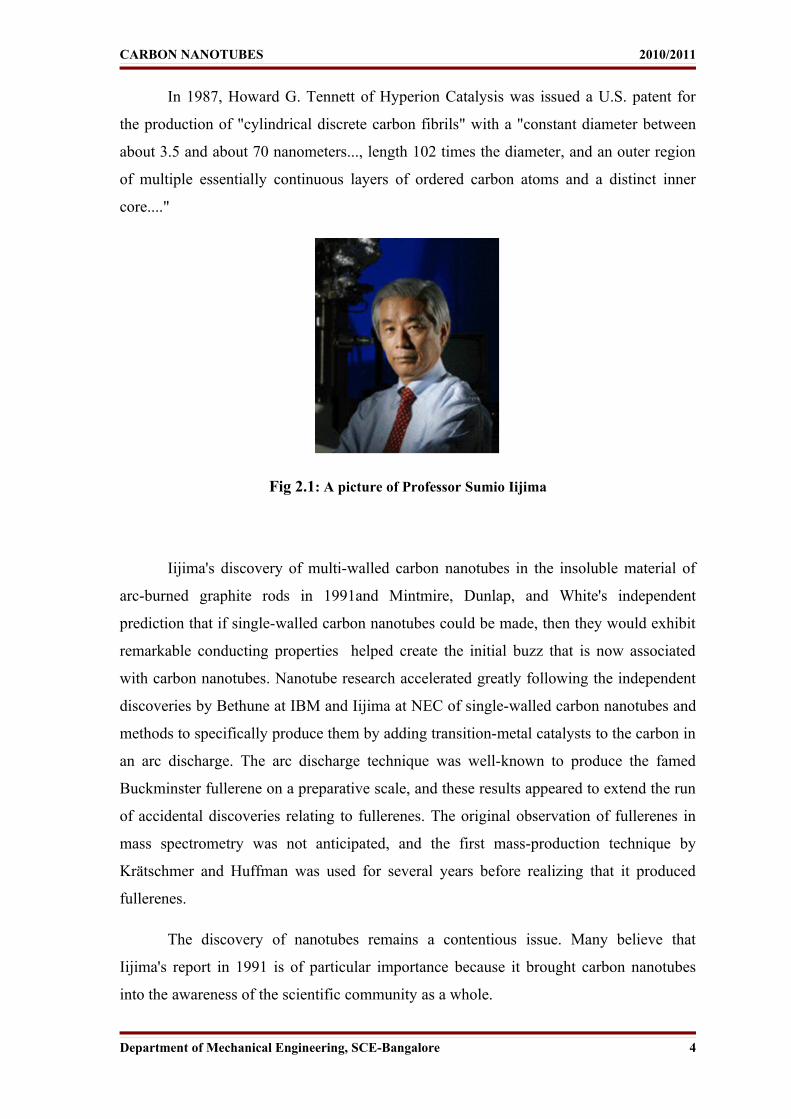
The observation of the longest carbon nanotubes (18.5 cm long) was reported in 2009. These nanotubes were grown on Si substrates using an improved chemical vapour deposition (CVD) method and represent electrically uniform arrays of single-walled carbon nanotubes. The shortest carbon nanotube is the organic compound cycloparaphenylene which was synthesized in early 2009. The thinnest carbon nanotube is armchair (2, 2) CNT with a diameter of 3 Å. This nanotube was grown inside a multi-walled carbon nanotube.
Department of Mechanical Engineering, SCE-Bangalore 10
CARBON NANOTUBES 2010/2011
Assigning of carbon nanotube type was done by combination of high-resolution transmission electron microscopy (HRTEM), Raman spectroscopy and density functional theory (DFT) calculations. The thinnest freestanding single-walled carbon nanotube is about 4.3 Å in diameter. Researchers suggested that it can be either (5, 1) or (4, 2) SWCNT, but exact type of carbon nanotube remains questionable. (3, 3), (4, 3) and (5, 1) carbon nanotubes (all about 4 Å in diameter) were unambiguously identified using more precise aberration-corrected high-resolution transmission electron microscopy. However, they were found inside of double-walled carbon nanotubes.
Fig 4.4: Cycloparaphenylene - the shortest carbon nanotube.
Department of Mechanical Engineering, SCE-Bangalore 11

CARBON NANOTUBES 2010/2011
CHAPTER: 5
PROPERTIES OF CARBON NANO TUBES
5.1 Strength
Carbon nanotubes are the strongest and stiffest materials yet discovered in terms
of tensile strength and elastic modulus respectively. This strength results from the
covalent sp² bonds formed between the individual carbon atoms. In 2000, a multi-walled
carbon nanotube was tested to have a tensile strength of 63 gigapascals (GPa) (This, for
illustration, translates into the ability to endure tension of a weight equivalent to 6422 kg
on a cable with cross-section of 1 mm2.) Since carbon nanotubes have a low density for a
solid of 1.3 to 1.4 g*cm−3, its specific strength of up to 48,000 KN*m*kg−1 is the best of
known materials, compared to high-carbon steel's 154 KN*m*kg−1.
Under excessive tensile strain, the tubes will undergo plastic deformation, which
means the deformation is permanent. This deformation begins at strains of approximately
5% and can increase the maximum strain the tubes undergo before fracture by releasing
strain energy. CNTs are not nearly as strong under compression. Because of their hollow
structure and high aspect ratio, they tend to undergo buckling when placed under
compressive, torsional or bending stress.
The above discussion referred to axial properties of the nanotube, whereas simple
geometrical considerations suggest that carbon nanotubes should be much softer in the
radial direction than along the tube axis. Indeed, TEM observation of radial elasticity
suggested that even the Van der Waal’s forces can deform two adjacent nanotubes. Nano
indentation experiments performed by several groups on multi-walled carbon nanotubes
and tapping/contact mode atomic force microscope measurement performed on single-
walled carbon nanotube, indicated Young's modulus of the order of several GPa
confirming that CNTs are indeed rather soft in the radial direction.
Department of Mechanical Engineering, SCE-Bangalore 12

CARBON NANOTUBES 2010/2011
5.2. Hardness
Standard single walled carbon nanotubes can withstand a pressure up to 24GPa
without deformation. They then undergo a transformation to super hard phase nanotubes.
Maximum pressures measured using current experimental techniques are around 55GPa.
However, these new super hard phase nanotubes collapse at an even higher, albeit
unknown, pressure. The bulk modulus of super hard phase nanotubes is 462 to 546 GPa,
even higher than that of diamond (420 GPa for single diamond crystal).
5.3 Kinetic
Multi-walled nanotubes are multiple concentric nanotubes precisely nested
within one another. These exhibit a striking telescoping property whereby an inner
nanotube core may slide, almost without friction, within its outer nanotube shell, thus
creating an atomically perfect linear or rotational bearing. This is one of the first true
examples of molecular nanotechnology, the precise positioning of atoms to create useful
machines. Already, this property has been utilized to create the world's smallest rotational
motor. Future applications such as a gigahertz mechanical oscillator are also envisaged.
5.4 Electrical
Due to the symmetry and unique electronic structure of graphene, the structure
of a nanotube strongly affects its electrical properties. For a given (n, m) nanotube, if n =
m, the nanotube is metallic; if n − m is a multiple of 3, then the nanotube is
semiconducting with a very small band gap, otherwise the nanotube is a moderate
semiconductor. Thus all armchair (n = m) nanotubes are metallic, and nanotubes (6, 4),
(9, 1), etc. are semiconducting.
However, this rule has exceptions, because curvature effects in small diameter
carbon nanotubes can influence strongly electrical properties. Thus, a (5, 0) SWCNT that
should be semiconducting in fact is metallic according to the calculations. Likewise, vice
versa-- zigzag and chiral SWCNTs with small diameters that should be metallic have
finite gap (armchair nanotubes remain metallic).
Department of Mechanical Engineering, SCE-Bangalore 13

CARBON NANOTUBES 2010/2011
In theory, metallic nanotubes can carry an electric current density of 4 × 10⁹
A/cm2 which is more than 1,000 times greater than metals such as copper, where for
copper interconnects current densities are limited by electro-migration. Multi-walled
carbon nanotubes with interconnected inner shells show superconductivity with a
relatively high transition temperature Tc = 12 K. In contrast, the Tc value is an order of
magnitude lower for ropes of single-walled carbon nanotubes or for MWNTs with usual,
non-interconnected shells.
5.5 Optical
Within materials science, the optical properties of carbon nanotubes refer
specifically to the absorption, photoluminescence, and Raman spectroscopy of carbon
nanotubes. Spectroscopic methods offer the possibility of quick and non-destructive
characterization of relatively large amounts of carbon nanotubes. There is a strong
demand for such characterization from the industrial point of view: numerous parameters
of the nanotube synthesis can be changed, intentionally or unintentionally, to alter the
nanotube quality. As shown below, optical absorption, photoluminescence and Raman
spectroscopies allow quick and reliable characterization of this "nanotube quality" in
terms of non-tubular carbon content, structure (chirality) of the produced nanotubes, and
structural defects. Those features determine nearly any other properties such as optical,
mechanical, and electrical properties.
Carbon nanotubes are unique "one dimensional systems" which can be envisioned
as rolled single sheets of graphite (or more precisely graphene). This rolling can be done
at different angles and curvatures resulting in different nanotube properties. The diameter
typically varies in the range 0.4–40 nm (i.e. "only" ~100 times), but the length can vary
~10,000 times reaching 4 cm. Thus the nanotube aspect ratio, or the length-to-diameter
ratio, can be as high as 132,000,000:1, which is unequalled by any other material.
Consequently, all the properties of the carbon nanotubes relative to those of typical
semiconductors are extremely anisotropic (directionally dependent) and tunable.
Whereas mechanical, electrical and electrochemical (super capacitor) properties of
the carbon nanotubes are well established and have immediate applications, the practical
use of optical properties is yet unclear. The aforementioned tunability of properties is
potentially useful in optics and photonics. In particular, light-emitting diodes (LEDs) and
photo-detectors based on a single nanotube have been produced in the lab.
Department of Mechanical Engineering, SCE-Bangalore 14

CARBON NANOTUBES 2010/2011
Their unique feature is not the efficiency, which is yet relatively low, but the
narrow selectivity in the wavelength of emission and detection of light and the possibility
of its fine tuning through the nanotube structure. In addition, bolometer and
optoelectronic memory devices have been realised on ensembles of single-walled carbon
nanotubes.
5.6 Thermal
All nanotubes are expected to be very good thermal conductors along the tube,
exhibiting a property known as "ballistic conduction", but good insulators laterally to the
tube axis. Measurements show that a SWNT has a room-temperature thermal conductivity
along its axis of about 3500 W*m−1*K−1; compare this to copper, a metal well-known for
its good thermal conductivity, which transmits 385 W*m−1*K−1. A SWNT has a room-
temperature thermal conductivity across its axis (in the radial direction) of about 1.52
W*m−1*K−1, which is about as thermally conductive as soil. The temperature stability of
carbon nanotubes is estimated to be up to 2800 °C in vacuum and about 750 °C in air.
Department of Mechanical Engineering, SCE-Bangalore 15

CARBON NANOTUBES 2010/2011
CHAPTER: 6
SYNTHESIS
In this section, different techniques for nanotube synthesis and their current status
are briefly explained. First, the growth mechanism is explained, as it is almost general for
all techniques. However, typical conditions are stated at the sections of all the different
techniques. The largest interest is in the newest methods for each technique and the
possibilities of scaling up.
Carbon nanotubes are generally produced by three main techniques, arc discharge,
laser ablation and chemical vapour deposition. In arc discharge, a vapour is created by an
arc discharge between two carbon electrodes with or without catalyst. Nanotubes self-
assemble from the resulting carbon vapour. In the laser ablation technique, a high-power
laser beam impinges on a volume of carbon -containing feedstock gas (methane or carbon
monoxide). At the moment, laser ablation produces a small amount of clean nanotubes,
whereas arc discharge methods generally produce large quantities of impure material. In
general, chemical vapour deposition (CVD) results in MWNTs or poor quality SWNTs.
The SWNTs produced with CVD have a large diameter range, which can be poorly
controlled. But on the other hand, this method is very easy to scale up, what favours
commercial production.
6.1 Growth mechanism
The way in which nanotubes are formed is not exactly known. The growth
mechanism is still a subject of controversy, and more than one mechanism might be
operative during the formation of CNTs. One of the mechanisms consists out of three
steps. First a precursor to the formation of nanotubes and fullerenes, C2, is formed on the
surface of the metal catalyst particle. From this metastable carbide particle, a rod-like
carbon is formed rapidly. Secondly there is a slow graphitisation of its wall. This
mechanism is based on in-situ TEM observations.
The exact atmospheric conditions depend on the technique used later on these will
be explained for each technique as they are specific for a technique. The actual growth of
the nanotube seems to be the same for all techniques mentioned.
Department of Mechanical Engineering, SCE-Bangalore 16

CARBON NANOTUBES 2010/2011
Figure 6.1: Visualisation of a possible carbon nanotube growth mechanism.
There are several theories on the exact growth mechanism for nanotubes. One
theory postulates that metal catalyst particles are floating or are supported on graphite or
another substrate. It presumes that the catalyst particles are spherical or pear-shaped, in
which case the deposition will take place on only one half of the surface (this is the lower
curvature side for the pear shaped particles). The carbon diffuses along the concentration
gradient and precipitates on the opposite half, around and below the bisecting diameter.
However, it does not precipitate from the apex of the hemisphere, which accounts for the
hollow core that is characteristic of these filaments. For supported metals, filaments can
form either by "extrusion (also known as base growth)" in which the nanotube grows
upwards from the metal particles that remain attached to the substrate, or the particles
detach and move at the head of the growing nanotube, labelled "tip-growth". Depending
on the size of the catalyst particles, SWNT or MWNT are grown. In arc discharge, if no
catalyst is present in the graphite, MWNT will be grown on the C2-particles that are
formed in the plasma.
Department of Mechanical Engineering, SCE-Bangalore 17

CARBON NANOTUBES 2010/2011
6.2 Arc discharge
The carbon arc discharge method, initially used for producing C60 fullerenes, is the
most common and perhaps easiest way to produce carbon nanotubes as it is rather simple
to undertake. However, it is a technique that produces a mixture of components and
requires separating nanotubes from the soot and the catalytic metals present in the crude
product.
This method creates nanotubes through arc-vaporisation of two carbon rods placed
end to end, separated by approximately 1mm, in an enclosure that is usually filled with
inert gas (helium, argon) at low pressure (between 50 and 700 mbar). Recent
investigations have shown that it is also possible to create nanotubes with the arc method
in liquid nitrogen. A direct current of 50 to 100 A driven by approximately 20 V creates a
high temperature discharge between the two electrodes. The discharge vaporises one of
the carbon rods and forms a small rod shaped deposit on the other rod. Producing
nanotubes in high yield depends on the uniformity of the plasma arc and the temperature
of the deposit form on the carbon electrode.
Insight in the growth mechanism is increasing and measurements have shown that
different diameter distributions have been found depending on the mixture of helium and
argon. These mixtures have different diffusions coefficients and thermal conductivities.
These properties affect the speed with which the carbon and catalyst molecules diffuse
and cool, affecting nanotube diameter in the arc process. This implies that single-layer
tubules nucleate and grow on metal particles in different sizes depending on the
quenching rate in the plasma and it suggests that temperature and carbon and metal
catalyst densities affect the diameter distribution of nanotubes. Depending on the exact
technique, it is possible to selectively grow SWNTs or MWNTs, which is shown in
Figure 6.2. Two distinct methods of synthesis can be performed with the arc discharge
apparatus.
Department of Mechanical Engineering, SCE-Bangalore 18

CARBON NANOTUBES 2010/2011
Fig 6.2: Experimental setup of an arc discharge apparatus
6.2.1 Synthesis of SWNT
If SWNTs are preferable, the anode has to be doped with metal catalyst, such as
Fe, Co, Ni, Y or Mo. A lot of elements and mixtures of elements have been tested by
various authors and it is noted that the results vary a lot, even though they use the same
elements. This is not surprising as experimental conditions differ. The quantity and
quality of the nanotubes obtained depend on various parameters such as the metal
concentration, inert gas pressure, kind of gas, the current and system geometry. Usually
the diameter is in the range of 1.2 to 1.4 nm. A couple of ways to improve the process of
arc discharge are stated below.
a) Inert gas
The most common problems with SWNT synthesis are that the product contains a
lot of metal catalyst, SWNTs have defects and purification is hard to perform. On the
other hand, an advantage is that the diameter can slightly be controlled by changing
thermal transfer and diffusion, and hence condensation of atomic carbon and metals
between the plasma and the vicinity of the cathode can control nanotube diameter in the
arc process. This was shown in an experiment in which different mixtures of inert gases
were used. It appeared that argon, with a lower thermal conductivity and diffusion
coefficient, gave SWNTs with a smaller diameter of approximately 1.2 nm. A linear fit of
the average nanotube diameter showed a 0.2 nm diameter decrease per 10 % increase in
argon helium ratio, when nickel/yttrium was used (C/Ni/Y was 94.8:4.2:1) as catalyst.
Department of Mechanical Engineering, SCE-Bangalore 19

CARBON NANOTUBES 2010/2011
b) Optical plasma control
A second way of control is plasma control by changing the anode to cathode
distance (ACD). The ACD is adjusted in order to obtain strong visible vortices around the
cathode. This enhances anode vaporisation, which improves nanotubes formation.
Combined with controlling the argon-helium mixture, one can simultaneously control the
macroscopic and microscopic parameters of the nanotubes formed. With a nickel and
yttrium catalyst (C/Ni/Y is 94.8:4.2:1) the optimum nanotube yield was found at a
pressure of 660 mbar for pure helium and 100 mbar for pure argon. The nanotube
diameter ranges from 1.27 to 1.37 nanometre.
c) Catalyst
Knowing that chemical vapour deposition (CVD) could give SWNTs with a
diameter of 0.6-1.2 nm, researchers tried the same catalyst as used in CVD on arc
discharge. Not all of the catalysts used appeared to result in nanotubes for both methods.
But there seemed to be a correlation of diameter of SWNTs synthesised by CVD and arc
discharge. As a result, the diameter can be controllably lowered to a range of 0.6-1.2 nm
with arc-discharge. Using a mixture of Co and Mo in high concentrations as catalyst
resulted in this result. These diameters are considerably smaller than 1.2-1.4 nm, which is
the usual size gained from arc-discharge.
e) Open air synthesis with welding arc torch
Only a couple of years ago, researchers discovered that it was possible to form
MWNTs in open air. A welding arc torch was operated in open air and the process was
shielded with an argon gas flow. The anode and cathode were made of graphite
containing Ni and Y (Ni/Y is 4.2:1 at. %).
Fig 6.3: Experimental set-up of the torch arc method in open air.
Department of Mechanical Engineering, SCE-Bangalore 20

CARBON NANOTUBES 2010/2011
This method was modified for preparing SWNTs. A plate target made of graphite
containing metal catalyst Ni and Y (Ni/Y is 3.6:0.8 at. per cent), was fixed at the sidewall
of a water-cooled, steel based electrode. The torch arc aimed at the edge of the target and
the soot was deposited on the substrate behind the target (see Figure 6.3). The arc was
operated at a direct current of 100 A. and shielding argon gas flowed through the torch,
enhancing the arc jet formation beyond the target. In the soot, carbon Nano horns (CNHs)
and bundles of SWNT with an average diameter of 1.32 nm were found. However, the
yield was much lower than for the conventional low-pressure arc discharge method.
There are two reasons for this fact. At first, because of the open air, the lighter soot will
escape into the atmosphere. Secondly, the carbon vapour might be oxidised and emitted
as carbon dioxide gas. In order to improve the yield in this method, contrivances for
collecting soot and development of an appropriate target are required. This method
promises to be convenient and inexpensive once the conditions for higher yield are
optimised. With a Ni/Y catalyst (Ni/Y is 3.6:0.8), SWNT bundles and CNHs are formed.
In this case the SWNTs have a diameter of approximately 1.32 nm.
6.2.2 Synthesis of MWNT
If both electrodes are graphite, the main product will be MWNTs. But next to
MWNTs a lot of side products are formed such as fullerenes, amorphous carbon, and
some graphite sheets. Purifying the MWNTs, means loss of structure and disorders the
walls. However scientists are developing ways to gain pure MWNTs in a large-scale
process without purification. Typical sizes for MWNTs are an inner diameter of 1-3 nm
and an outer diameter of approximately 10 nm. Because no catalyst is involved in this
process, there is no need for a heavy acidic purification step. This means, the MWNT, can
be synthesised with a low amount of defects.
a) Synthesis in liquid nitrogen
A first, possibly economical route to highly crystalline MWNTs is the arc-
discharge method in liquid nitrogen, with this route mass production is also possible. For
this option low pressures and expensive inert gasses are not needed.
Department of Mechanical Engineering, SCE-Bangalore 21

CARBON NANOTUBES 2010/2011
Fig 6.4: Schematic drawings of the arc discharge apparatus in liquid nitrogen.
The content of the MWNTs can be as high as 70 % of the reaction product.
Analysis with Auger-spectroscopy revealed that no nitrogen was incorporated in the
MWNTs. There is a strong possibility that SWNTs can be produced with the same
apparatus under different conditions.
b) Magnetic field synthesis
Synthesis of MWNTs in a magnetic field gives defect-free and high purity
MWNTs that can be applied as nano-sized electric wires for device fabrication. In this
case, the arc discharge synthesis was controlled by a magnetic field around the arc
plasma.
Fig 6.5: Schematic diagram of the synthesis system for MWNTs in a magnetic field.
Extremely pure graphite rods (purity > 99.999 %) were used as electrodes. Highly
pure MWNTs (purity > 95 %) were obtained without further purification, which disorders
walls of MWNTs.
Department of Mechanical Engineering, SCE-Bangalore 22

CARBON NANOTUBES 2010/2011
c) Plasma rotating arc discharge
A second possibly economical route to mass production of MWNTs is synthesis
by plasma rotating arc discharge technique. The centrifugal force caused by the rotation
generates turbulence and accelerates the carbon vapour perpendicular to the anode. In
addition, the rotation distributes the micro discharges uniformly and generates stable
plasma. Consequently, it increases the plasma volume and raises the plasma temperature.
Fig6.6: Schematic diagram of plasma rotating electrode system.
At a rotation speed of 5000 rpm a yield of 60 % was found at a formation
temperature of 1025 °C without the use of a catalyst. The yield increases up to 90% after
purification if the rotation speed is increased and the temperature is enlarged to 1150 °C.
The diameter size was not mentioned in this publication.
6.3 Laser ablation
In 1995, Smalley's group at Rice University reported the synthesis of carbon
nanotubes by laser vaporisation. The laser vaporisation apparatus used by Smalley's group
is shown in Figure 6.7. A pulsed or continuous laser is used to vaporise a graphite target
in an oven at 1200 °C. The main difference between continuous and pulsed laser, is that
the pulsed laser demands a much higher light intensity (100 kW/cm2 compared with 12
kW/cm2). The oven is filled with helium or argon gas in order to keep the pressure at 500
Torr. A very hot vapour plume forms, then expands and cools rapidly. As the vaporised
species cool, small carbon molecules and atoms quickly condense to form larger clusters,
possibly including fullerenes. The catalysts also begin to condense, but more slowly at
first, and attach to carbon clusters and prevent their closing into cage structures. Catalysts
may even open cage structures when they attach to them.
Department of Mechanical Engineering, SCE-Bangalore 23

CARBON NANOTUBES 2010/2011
From these initial clusters, tubular molecules grow into single-wall carbon
nanotubes until the catalyst particles become too large, or until conditions have cooled
sufficiently that carbon no longer can diffuse through or over the surface of the catalyst
particles. It is also possible that the particles become that much coated with a carbon layer
that they cannot absorb more and the nanotube stops growing. The SWNTs formed in this
case are bundled together by van der Waals forces.
Fig 6.7: Schematic drawing of a laser ablation apparatus.
There are some striking, but not exact similarities, in the comparison of the
spectral emission of excited species in laser ablation of a composite graphite target with
that of laser-irradiated C60 vapour. This suggests that fullerenes are also produced by laser
ablation of catalyst-filled graphite, as is the case when no catalysts are included in the
target. However, subsequent laser pulses excite fullerenes to emit C2 that adsorbs on
catalyst particles and feeds SWNT growth. However, there is insufficient evidence to
conclude this with certainty. Laser ablation is almost similar to arc discharge, since the
optimum background gas and catalyst mix is the same as in the arc discharge process.
This might be due to very similar reaction conditions needed, and the reactions probably
occur with the same mechanism.
6.3.1 Ultra-fast pulses from a free electron laser (FEL) method
Usually the pulses in an Nd: YAG system has width of approximately 10 ns, in
this FEL system the pulse width is ~ 400 fs. The repetition rate of the pulse is enormously
increased from 10 Hz to 75 MHz. To give the beam the same amount of energy as the
pulse in an Nd: YAG system, the pulse has to be focused.
Department of Mechanical Engineering, SCE-Bangalore 24

CARBON NANOTUBES 2010/2011
The intensity of the laser bundle behind the lens reaches ~5 x 10¹¹ W/cm2, which
is about 1000 times greater than in Nd: YAG systems. A jet of preheated (1000 °C) argon
through a nozzle tip is situated close to the rotating graphite target, which contains the
catalyst. The argon gas deflects the ablation plume approximately 90° away from the
incident FEL beam direction, clearing away the carbon vapour from the region in front of
the target. The produced SWNT soot is collected in a cold finger. This process can be
seen in Figure 6.8. The yield at this moment is 1, 5 g/h, which is at 20 % of the maximum
power of the not yet upgraded FEL. If the FEL is upgraded to full power and is working
at 100 % power, a yield of 45 g/h could be reached since the yield was not limited by the
laser power.
Fig 6.8: Schematic drawings of the ultra-fast-pulsed laser ablation apparatus.
With this method the maximum achievable yield with the current lasers is 45 g/h,
with a NiCo or NiY catalyst, in argon atmosphere at 1000 °C and a wavelength of ~3000
nm. The SWNTs produced in bundles of 8-200 nm and a length of 5-20 microns has a
diameter range 1-1.4 nm.
6.4 Chemical vapour deposition
Chemical vapour deposition (CVD) synthesis is achieved by putting a carbon
source in the gas phase and using an energy source, such as plasma or a resistively heated
coil, to transfer energy to a gaseous carbon molecule. Commonly used gaseous carbon
sources include methane, carbon monoxide and acetylene. The energy source is used to
"crack" the molecule into reactive atomic carbon. Then, the carbon diffuses towards the
substrate, which is heated and coated with a catalyst (usually a first row transition metal
such as Ni, Fe or Co) where it will bind. Carbon nanotubes will be formed if the proper
parameters are maintained.
Department of Mechanical Engineering, SCE-Bangalore 25

CARBON NANOTUBES 2010/2011
Excellent alignment, as well as positional control on nanometre scale, can be
achieved by using CVD. Control over the diameter, as well as the growth rate of the
nanotubes can also be maintained. The appropriate metal catalyst can preferentially grow
single rather than multi-walled nanotubes.
CVD carbon nanotube synthesis is essentially a two-step process consisting of a
catalyst preparation step followed by the actual synthesis of the nanotube. The catalyst is
generally prepared by sputtering a transition metal onto a substrate and then using either
chemical etching or thermal annealing to induce catalyst particle nucleation. Thermal
annealing results in cluster formation on the substrate, from which the nanotubes will
grow. Ammonia may be used as the etchant. The temperatures for the synthesis of
nanotubes by CVD are generally within the 650-900 oC range. Typical yields for CVD are
approximately 30%.These are the basic principles of the CVD process. In the last
decennia, different techniques for the carbon nanotubes synthesis with CVD have been
developed, such as plasma enhanced CVD, thermal chemical CVD, alcohol catalytic
CVD, vapour phase growth, aero gel-supported CVD and laser-assisted CVD. These
different techniques will be explained more detailed in this chapter.
6.4.1 Plasma enhanced chemical vapour deposition
The plasma enhanced CVD method generates a glow discharge in a chamber or a
reaction furnace by a high frequency voltage applied to both electrodes. Figure 6.9 shows
a schematic diagram of a typical plasma CVD apparatus with a parallel plate electrode
structure.
Fig 6.9: Schematic diagram of plasma CVD apparatus.
Department of Mechanical Engineering, SCE-Bangalore 26

CARBON NANOTUBES 2010/2011
A substrate is placed on the grounded electrode. In order to form a uniform film,
the reaction gas is supplied from the opposite plate. Catalytic metal, such as Fe, Ni and
Co are used on for example a Si, SiO2, or glass substrate using thermal CVD or
sputtering. After nanoscopic fine metal particles are formed, carbon nanotubes will be
grown on the metal particles on the substrate by glow discharge generated from high
frequency power. A carbon containing reaction gas, such as C2H2, CH4, C2H4, C2H6, CO is
supplied to the chamber during the discharge. The catalyst has a strong effect on the
nanotube diameter, growth rate, wall thickness, morphology and microstructure. Ni seems
to be the most suitable pure-metal catalyst for the growth of aligned multi-walled carbon
nanotubes (MWNTs). The diameter of the MWNTs is approximately 15 nm. The highest
yield of carbon nanotubes achieved was about 50% and was obtained at relatively low
temperatures (below 330o C).
6.4.2 Thermal chemical vapour deposition
In this method Fe, Ni, Co or an alloy of the three catalytic metals is initially
deposited on a substrate. After the substrate is etched in a diluted HF solution with
distilled water, the specimen is placed in a quartz boat. The boat is positioned in a CVD
reaction furnace, and nanometre-sized catalytic metal particles are formed after an
additional etching of the catalytic metal film using NH3 gas at a temperature of 750 to
1050o C. As carbon nanotubes are grown on these fine catalytic metal particles in CVD
synthesis, forming these fine catalytic metal particles is the most important process.
Figure 6.10 shows a schematic diagram of thermal CVD apparatus in the synthesis of
carbon nanotubes.
Fig 6.10: Schematic diagram of thermal CVD apparatus.
Department of Mechanical Engineering, SCE-Bangalore 27
CARBON NANOTUBES 2010/2011
When growing carbon nanotubes on a Fe catalytic film by thermal CVD, the
diameter range of the carbon nanotubes depends on the thickness of the catalytic film. By
using a thickness of 13 nm, the diameter distribution lies between 30 and 40 nm. When a
thickness of 27 nm is used, the diameter range is between 100 and 200 nm. The carbon
nanotubes formed are multi-walled.
6.4.3 Alcohol catalytic chemical vapour deposition
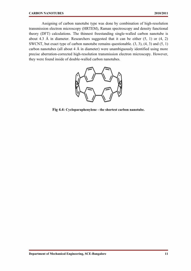
Alcohol catalytic CVD (ACCVD) is a technique that is being intensively
developed for the possibility of large-scale production of high quality single wall
nanotubes SWNTs at low cost. In this technique, evaporated alcohols, methanol and
ethanol, are being utilised over iron and cobalt catalytic metal particles supported with
zeolite. Generation is possible is possible at a relatively low minimum temperature of
about 550 oC. It seems that hydroxyl radicals, who come from reacting alcohol on
catalytic metal particles, remove carbon atoms with dangling bonds, which are obstacles
in creating high-purity SWNTs. The diameter of the SWNTs is about 1 nm. Figure 6.11
shows the ACCVD experimental apparatus.
Fig6.11: ACCVD experimental apparatus.
The lower reaction temperature and the high-purity features of this ACCVD
technique guarantee an easy possibility to scale production up at low cost. Furthermore,
the reaction temperature, which is lower than 600 oC, ensures that this technique is easily
applicable for the direct growth of SWNTs on semiconductor devices already patterned
with aluminium.
Department of Mechanical Engineering, SCE-Bangalore 28

CARBON NANOTUBES 2010/2011
6.4.4 Aero gel-supported chemical vapour deposition
In this method SWNTs are synthesised by disintegration of carbon monoxide on
an aero gel-supported Fe/Mo catalyst. There are many important factors that affect the
yield and quality of SWNTs, including the surface area of the supporting material,
reaction temperature and feeding gas. Because of the high surface area, the porosity and
ultra-light density of the aero gels, the productivity of the catalyst is much higher than in
other methods. After a simple acidic treatment and a oxidation process high purity
(>99%) SWNTs can be obtained. When using CO as feeding gas the yield of the
nanotubes is lower but the overall purity of the materials is very good. The diameter
distribution of de nanotubes is between 1, 0 nm and 1, 5 nm. The optimal reaction
temperature is approximately 860 oC .
6.4.5 Laser-assisted thermal chemical vapour deposition
In laser-assisted thermal CVD (LCVD) a medium power, continuous wave CO2
laser, which was perpendicularly directed onto a substrate, pyrolysis sensitised mixtures
of Fe (CO)5 vapour and acetylene in a flow reactor. The carbon nanotubes are formed by
the catalysing action of the very small iron particles. Figure 6.12 shows the experimental
set-up for laser-assisted CVD. By using a reactant gas mixture of iron pentacarbonyl
vapour, ethylene and acetylene both single- and multi-walled carbon nanotubes are
produced. Silica is used as substrate. The diameters of the SWNTs range from 0.7 to 2.5
nm. The diameter range of the MWNTs is 30 to 80 nm.
Fig6.12: Experimental set-up for laser-assisted CVD.
Department of Mechanical Engineering, SCE-Bangalore 29

CARBON NANOTUBES 2010/2011
CHAPTER 7
APPLICATIONS OF CARBON NANOTUBES
Current use and application of nanotubes has mostly been limited to the use of bulk
nanotubes, which is a mass of rather unorganized fragments of nanotubes. Bulk nanotube
materials may never achieve a tensile strength similar to that of individual tubes, but such
composites may nevertheless yield strengths sufficient for many applications. Bulk
carbon nanotubes have already been used as composite fibers in polymers to improve the
mechanical, thermal and electrical properties of the bulk product.
• Paper battery: a paper battery is a battery engineered to use a paper-thin sheet of
cellulose (which is the major constituent of regular paper, among other things) infused
with aligned carbon nanotubes. The nanotubes act as electrodes; allowing the storage
devices to conduct electricity. The battery, which functions as both a lithium-ion battery
and a supercapacitor, can provide a long, steady power output comparable to a
conventional battery, as well as a supercapacitor’s quick burst of high energy—and while
a conventional battery contains a number of separate components, the paper battery
integrates all of the battery components in a single structure, making it more energy
efficient.
• Solar cells: Solar cells developed at the New Jersey Institute of Technology use a
carbon nanotube complex, formed by a mixture of carbon nanotubes and carbon
buckyballs (known as fullerenes) to form snake-like structures. Buckyballs trap electrons,
although they can't make electrons flow. Add sunlight to excite the polymers, and the
buckyballs will grab the electrons. Nanotubes, behaving like copper wires, will then be
able to make the electrons or current flow.
• Nano radio: A nanoradio, a radio receiver consisting of a single nanotube, was
demonstrated in 2007. In 2008 it was shown that a sheet of nanotubes can operate as a
loudspeaker if an alternating current is applied. The sound is not produced through
vibration but thermo acoustically.
• Blacker than Black? : Black is black, right? Not so, according to a team of NASA
engineers now developing a blacker-than pitch material that will help scientists gather
hard-to-obtain scientific measurements or observe currently unseen astronomical objects,
Department of Mechanical Engineering, SCE-Bangalore 30
CARBON NANOTUBES 2010/2011
like Earth-sized planets in orbit around other stars.The nanotech-based material now
being developed by a team of 10 technologists at the NASA Goddard Space Flight Center
in Greenbelt, Md., is a thin coating of multi-walled carbon nanotubes — tiny hollow
tubes made of pure carbon about 10,000 times thinner than a strand of human hair.
Nanotubes have a multitude of potential uses, particularly in electronics and advanced
materials due to their unique electrical properties and extraordinary strength. But in this
application, NASA is interested in using the technology to help suppress errant light that
has a funny way of ricocheting off instrument components and contaminating
measurements.
• Space elevator project: Carbon nanotube ribbons created in a University of Texas
laboratory may stretch all the way into space. According to research to be published in
Science today, Dr. Mei Zhang and his team have succeeded in creating yard-long ribbons
of carbon nanotubes - just the sort of ultra-light, ultra-strong filaments needed to create
the space elevator (among many other things). A space elevator is essentially a long cable
that is anchored on Earth at one end and "anchored" at the other end 35,000 kilometers
away by a satellite in geosynchronous orbit. Gravity and centripetal acceleration keeps
the cable taut; a small elevator, or car, can crawl up the elevator at a fraction of the energy
expenditure needed to actually hurl an object into orbit. Putting a satellite in orbit could
cost hundreds of dollars per pound, rather than $7,000 per pound as it does on the space
shuttle.
• Energy storage: Graphite, carbonaceous materials and carbon fibre electrodes are
commonly used in fuel cells, batteries and other electrochemical applications. Advantages
of considering nanotubes for energy storage are their small dimensions, smooth surface
topology and perfect surface specificity. The efficiency of fuel cells is determined by the
electron transfer rate at the carbon electrodes, which is the fastest on nanotubes following
ideal Nernstian behaviour. Electrochemical energy storage and gas phase intercalation
will be described more thoroughly in the following chapters of the report.
• Hydrogen storage: The advantage of hydrogen as energy source is that its combustion
product is water. In addition, hydrogen can be easily regenerated. For this reason, a
suitable hydrogen storage system is necessary, satisfying a combination of both volume
and weight limitations. The two commonly used means to store hydrogen are gas phase
and electrochemical adsorption.
Department of Mechanical Engineering, SCE-Bangalore 31

CARBON NANOTUBES 2010/2011
Because of their cylindrical and hollow geometry, and nanometre-scale diameters, it
has been predicted that carbon nanotubes can store a liquid or a gas in the inner cores
through a capillary effect. As a threshold for economical storage, the Department of
Energy has set storage requirements of 6.5 % by weight as the minimum level for
hydrogen fuel cells. It is reported that SWNTs were able to meet and sometimes exceed
this level by using gas phase adsorption (physisorption). Yet, most experimental reports
of high storage capacities are rather controversial so that it is difficult to assess the
applications potential. What lacks, is a detailed understanding of the hydrogen storage
mechanism and the effect of materials processing on this mechanism. Another possibility
for hydrogen storage is electrochemical storage. In this case not a hydrogen molecule but
an H atom is adsorbed. This is called chemisorption.
• Lithium intercalation: The basic principle of rechargeable lithium batteries is
electrochemical intercalation and de-intercalation of lithium in both electrodes. An ideal
battery has a high-energy capacity, fast charging time and a long cycle time. The capacity
is determined by the lithium saturation concentration of the electrode materials. For Li,
this is the highest in nanotubes if all the interstitial sites (inter-shell van der Waals spaces,
inter-tube channels and inner cores) are accessible for Li intercalation. SWNTs have
shown to possess both highly reversible and irreversible capacities. Because of the large
observed voltage hysteresis, Li-intercalation in nanotubes is still unsuitable for battery
application. This feature can potentially be reduced or eliminated by processing, i.e.
cutting, the nanotubes to short segments.
• Electrochemical supercapacitors: Supercapacitors have a high capacitance and
potentially applicable in electronic devices. Typically, they are comprised two electrodes
separated by an insulating material that is ionically conducting in electrochemical
devices. The capacity of an electrochemical supercap inversely depends on the separation
between the charge on the electrode and the counter charge in the electrolyte. Because
this separation is about a nanometre for nanotubes in electrodes, very large capacities
result from the high nanotube surface area accessible to the electrolyte. In this way, a
large amount of charge injection occurs if only a small voltage is applied. This charge
injection is used for energy storage in nanotube supercapacitors. Generally speaking,
there is most interest in the double-layer supercapacitors and redox supercapacitors with
different charge-storage modes.
Department of Mechanical Engineering, SCE-Bangalore 32

CARBON NANOTUBES 2010/2011
• Field emitting devices: If a solid is subjected to a sufficiently high electric field,
electrons near the Fermi level can be extracted from the solid by tunnelling through the
surface potential barrier. This emission current depends on the strength of the local
electric field at the emission surface and its work function (which denotes the energy
necessary to extract an electron from its highest bounded state into the vacuum level).
The applied electric field must be very high in order to extract an electron. This condition
is fulfilled for carbon nanotubes, because their elongated shape ensures very large field
amplification. For technological applications, the emissive material should have a low
threshold emission field and large stability at high current density. Furthermore, an ideal
emitter is required to have a nanometre size diameter, a structural integrity, a high
electrical conductivity, a small energy spread and a large chemical stability. Carbon
nanotubes possess all these properties
• Transistors: The field-effect transistor - a three-terminal switching device - can be
constructed of only one semi-conducting SWNT. By applying a voltage to a gate
electrode, the nanotube can be switched from a conducting to an insulating state. Such
carbon nanotube transistors can be coupled together, working as a logical switch, the
basic component of computers.
• Other applications:
* Easton-Bell Sports, Inc. have been in partnership with Zyvex Performance Materials,
using CNT technology in a number of their bicycle components—including flat and riser
handlebars, cranks, forks, seat posts, stems and aero bars.
* Zyvex Performance Materials has also built a 54' maritime vessel, the Piranha
Unmanned Surface Vessel, as a technology demonstrator for what is possible using CNT
technology. CNTs help improve the structural performance of the vessel, resulting in a
lightweight 8,000 lb. boat that can carry a payload of 15,000 lb. over a range of 2,500
miles.
* Amroy Europe Oy manufactures Hybtonite carbon nanoepoxy resins where carbon
nanotubes have been chemically bond to epoxy, resulting composite material that is 20%
to 30% stronger than other composite materials. It has been used for wind turbines,
marine paints and variety of sports gear such as skis, ice hockey sticks, baseball bats,
hunting arrows and surfboards.
Department of Mechanical Engineering, SCE-Bangalore 33

CARBON NANOTUBES 2010/2011
CHAPTER 8
DRAWBACKS OF CARBON NANOTUBES
8.1Defects
As with any material, the existence of a crystallographic defect affects the material
properties. Defects can occur in the form of atomic vacancies. High levels of such defects
can lower the tensile strength by up to 85%. Another form of carbon nanotube defect is
the Stone Wales defect, which creates a pentagon and heptagon pair by rearrangement of
the bonds. Because of the very small structure of CNTs, the tensile strength of the tube is
dependent on its weakest segment in a similar manner to a chain, where the strength of
the weakest link becomes the maximum strength of the chain.
Crystallographic defects also affect the tube's electrical properties. A common
result is lowered conductivity through the defective region of the tube. A defect in
armchair-type tubes (which can conduct electricity) can cause the surrounding region to
become semiconducting, and single monoatomic vacancies induce magnetic properties.
Crystallographic defects strongly affect the tube's thermal properties. Such defects
lead to phonon scattering, which in turn increases the relaxation rate of the phonons. This
reduces the mean free path and reduces the thermal conductivity of nanotube structures.
Phonon transport simulations indicate that substitutional defects such as nitrogen or boron
will primarily lead to scattering of high-frequency optical phonons. However, larger-scale
defects such as Stone Wales defects cause phonon scattering over a wide range of
frequencies, leading to a greater reduction in thermal conductivity.
8.2 Toxicity
Determining the toxicity of carbon nanotubes has been one of the most pressing
questions in nanotechnology. Preliminary results highlight the difficulties in evaluating
the toxicity of this heterogeneous material. Parameters such as structure, size distribution,
surface area, surface chemistry, surface charge, and agglomeration state as well as purity
of the samples, have considerable impact on the reactivity of carbon nanotubes.
Department of Mechanical Engineering, SCE-Bangalore 34

CARBON NANOTUBES 2010/2011
However, available data clearly show that, under some conditions, nanotubes can
cross membrane barriers, which suggests that if raw materials reach the organs they can
induce harmful effects such as inflammatory and fibrotic reactions. A study led by
Alexandra Porter from the University of Cambridge shows that CNTs can enter human
cells and accumulate in the cytoplasm, causing cell death. Results of rodent studies
collectively show that regardless of the process by which CNTs were synthesized and the
types and amounts of metals they contained, CNTs were capable of producing
inflammation, epithelioid granulomas (microscopic nodules), fibrosis, and
biochemical/toxicological changes in the lungs. Comparative toxicity studies in which
mice were given equal weights of test materials showed that SWCNTs were more toxic
than quartz, which is considered a serious occupational health hazard when chronically
inhaled. As a control, ultrafine carbon black was shown to produce minimal lung
responses.
The needle-like fiber shape of CNTs, similar to asbestos fibers, raises fears that
widespread use of carbon nanotubes may lead to mesothelioma, cancer of the lining of the
lungs often caused by exposure to asbestos. A recently-published pilot study supports this
prediction. Scientists exposed the mesothelial lining of the body cavity of mice, as a
surrogate for the mesothelial lining of the chest cavity, to long multiwalled carbon
nanotubes and observed asbestos-like, length-dependent, pathogenic behavior which
included inflammation and formation of lesions known as granulomas. Authors of the
study conclude "This is of considerable importance, because research and business
communities continue to invest heavily in carbon nanotubes for a wide range of products
under the assumption that they are no more hazardous than graphite. Our results suggest
the need for further research and great caution before introducing such products into the
market if long-term harm is to be avoided."According to co-author Dr. Andrew Maynard
"This study is exactly the kind of strategic, highly focused research needed to ensure the
safe and responsible development of nanotechnology. It looks at a specific nanoscale
material expected to have widespread commercial applications and asks specific
questions about a specific health hazard. Even though scientists have been raising
concerns about the safety of long, thin carbon nanotubes for over a decade, none of the
research needs in the current U.S. federal nanotechnology environment, health and safety
risk research strategy address this question." Although further research is required, results
presented today clearly demonstrate that, under certain conditions, especially those
involving chronic exposure, carbon nanotubes can pose a serious risk to human health.
Department of Mechanical Engineering, SCE-Bangalore 35

CARBON NANOTUBES 2010/2011
REFERENCES
1. Topics in Applied Physics; Carbon Nanotubes: Synthesis, Structure, Properties and
Applications, M.S. Dresselhaus, G. Dresselhaus, Ph. Avouris
2. Carbon Nanotube Electronics; Phaedon Avouris, member, IEEE; Joerg Appenzeller,
Richard Martel, and Shalom J. Wind, senior member, IEEE, proceedings of the IEEE,
Vol. 91, no. 11, November 2003
3. Carbon Nanotubes: Single molecule wires,Sarah Burke, Sean Collins, David Montiel,
Mikhail Sergeev
4. Journet, C. and Bernier, P. (1998), Production of carbon nanotubes. Applied, Physics,
5. Ijiima, S. (1993) Growth of carbon, nanotubes. Materials Science and Engineering B,
6. http://www.ipt.arc.nasa.gov
7. Carbon Nanotubes: Introduction to Nanotechnology 2003, Mads Brandbyge
8. http://students.chem.tue.nl/ifp03/applications.
Department of Mechanical Engineering, SCE-Bangalore 36