
ABL-H16R6-NN ABL-H16R6-PN ABL Series 1 2 3 4 2 · 2018. 6. 21. · 16-POINT RELAY TERMINAL BLOCK...
1
16-POINT RELAY TERMINAL BLOCK (screwless type) ABL Series DRW161130AB ② ① ③ 98.4 75.4 73.4 35.2 71.55 12.5 4 77.1 10.2 71.4 ● ABL-H16R6-NN ● ABL-H16R6-PN I N S T R U C T I O N M A N U A L Thank you for choosing our Autonics product. Please read the following safety considerations before use. 1. Fail-safe device must be installed when using the unit with machinery that may cause serious injury or substantial economic loss. (e.g. nuclear power control, medical equipment, ships, vehicles, railways, aircraft, combustion apparatus, safety equipment, crime/disaster prevention devices, etc.) Failure to follow this instruction may result in personal injury, fire, or economic loss. 2. Do not repair, or inspect the unit while connected to a power source. Failure to follow this instruction may result in fire or electric shock. 3. Do not use the unit where flammable or explosive gas, humidity, direct sunlight, radiant heat, vibration, or impact may be present. Failure to follow this instruction may result in fire or explosion. 4. Do not disassemble or modify the unit. Please contact us if necessary. Failure to follow this instruction may result in electric shock, fire, or product damage. 1. Do not use the unit outdoors. Failure to follow this instruction may result in shortening the life cycle of the unit, or electric shock. 2. Use the unit within the rated specifications. Failure to follow this instruction may result in shortening the life cycle of the unit, or fire. 3. Do not use water or oil-based detergent when cleaning the unit. Use dry cloth to clean the unit. Failure to follow this instruction may result in electric shock or product damage. 4. Keep dust and wire residue from flowing into the unit. Failure to follow this instruction may result in fire or product damage. Safety Considerations Warning Caution ※Please observe all safety considerations for safe and proper product operation to avoid hazards. ※Safety considerations are categorized as follows. Warning Failure to follow these instructions may result in serious injury or death. Caution Failure to follow these instructions may result in personal injury or product damage. ※The symbols used on the product and instruction manual represent the following symbol represents caution due to special circumstances in which hazards may occur. Model Terminal type Connector type No. of relay points Relay type Input logic Varistor installation ABL-H16R6-NN Screwless Hirose connector 16 OMRON G6B NPN Not installed ABL-H16R6-PN PNP Model A B C Applicable wires End Sleeve (ferrule terminal) crimp terminal 10 to 12.0 ≤ 2.0 ≤ 4.1 AWG22-16 (0.30 to 1.25mm 2 ) A C B (unit: mm) Crimp Terminal Specifications Connecting and removing end sleeve (ferrule terminal) crimp terminal at screwless type terminal block ● Connecting 1) Push the end sleeve (ferrule) crimp terminal towards direction ① to complete the connection. ● Removing 1) Press and hold the catch above the terminal in direction ② with a flathead screwdriver. 2) Pull and remove the end sleeve (ferrule) crimp terminal towards direction ③. ※The above specifications are subject to change and some models may be discontinued without notice. Connecting Crimp Terminals ※1: Please connect to a load using the same power supply. Connecting to a load from a different power supply may cause safety issues. ※2: Relay contact capacity for resistive load. ※3: The current consumption including LED current by one relay. ※4: When using stranded wire, use End Sleeve (ferrule terminal) crimp terminals. ※5: The weight includes packaging. The weight in parenthesis is for unit only. ※Environment resistance is rated at no freezing or condensation. Specifications Model ABL-H16R6-NN ABL-H16R6-PN Power supply 24VDC ±10% Rated load voltage & current ※1※2 250VAC 3A, 30VDC 3A Current consumption ※3 ≤ 20mA Output type 1a contact relay output Applied relay G6B-1174P-FD-US [OMRON] No. of relay points 16 Terminal type Screwless Terminal pitch ≥ 7.8mm Indicator Power indicator: red LED, operation indicator: blue LED Applied cable Solid wire Ø0.6 to Ø1.25mm Stranded wire ※4 AWG22-16 (0.3 to 1.25mm 2 ) Stripped wire length 8 to 10mm Insulation resistance ≥ 1,000MΩ (at 500VDC megger) Dielectric strength Between coil-contact 3,000VAC 50/60Hz for 1 minute Between same contacts 1,000VAC 50/60Hz for 1 minute Vibration Mechanical 1.5mm amplitude at frequency of 10 to 55Hz (for 1 min) in each X, Y, Z direction for 2 hours Malfunction 1.5mm amplitude at frequency of 10 to 55Hz (for 1 min) in each X, Y, Z direction for 10 minutes Shock Mechanical 1000m/s 2 (approx. 100G) in each X, Y, Z direction for 3 times Malfunction 100m/s 2 (approx. 10G) in each X, Y, Z direction for 3 times Environ- ment Ambient temp. -15 to 55℃, storage: -25 to 65℃ Ambient humi. 35 to 85%RH, storage: 35 to 85%RH Material Terminal block, Cover: Polycarbonate CASE&BASE: Modified Polyphenylene Oxide Accessory Jumper bar: 2 Protection structure IP20 (IEC standard) Approval Weight ※5 Approx. 446g (approx. 348g) ※The values are measured at 20ºC with a tolerance of ±10%. 1) Coil specifications Relay 2) Contact specifications Model Rated voltage Must operate voltage Must release voltage Rated current Coil resistance Power consumption G6B-1174P- FD-US 24VDC ≥ 70% of rated voltage ≤ 10% of rated voltage 8.3mA 2,880Ω 200mW Maker OMRON Model G6B-1174P-FD-US Contact Arrangement 1 Form A (SPST-1a) Material AgSnln Resistance (initial) 30mΩ (5VDC 1A) Rating Rated load (resistive load) 5A 250VAC 5A 30VDC Max. switching power 1,250VA 150W Max. switching voltage 380VAC 125VDC Max. switching current 5A Electrical charac- teristics Insulation resistance ≥ 1,000MΩ (at 500VDC megger) Dielectric strength Coil and contacts 3,000VAC 50/60Hz for 1 minute Open contacts 1,000VAC 50/60Hz for 1 minute Surge voltage 6,000V Operate time ≤ 20ms Release time ≤ 10ms Mechanical character- istics Vibration Mechanical 1.5mm amplitude at frequency of 10 to 55Hz (for 1 min) in each X, Y, Z direction for 1 hour Malfunction 1.5mm amplitude at frequency of 10 to 55Hz (for 1 min) in each X, Y, Z direction for 10 minute Shock Mechanical 1,000m/s 2 (approx. 100G) in each X, Y, Z direction for 3 times Malfunction 100m/s 2 (approx. 10G) X, Y, Z in each X, Y, Z direction for 3 times Life expectancy Mechanical ≥ 50,000,000 operations (at 18,000 times/hour) Electrical ≥ 100,000 operations (5A 250VAC, 30VDC) (at 30 times/min) Environ- ment Ambient temp. -25 to 70℃ Ambient humi. 5 to 85%RH Unit weight Approx. 5g ※Environment resistance is rated at no freezing or condensation. Mounting and removal at DIN rail ● Mounting 1) Pull the rail lock towards direction ①. 2) Attach the DIN rail connection part onto the DIN rail. 3) Push the unit towards direction ②, then push the rail lock in to lock into position. ● Removal 1) Insert a screwdriver into the rail lock hole and pull it towards direction ①. 2) Remove the unit by pulling the unit towards direction ②. Installation ① ① ② Rail lock DIN rail DIN rail connector Wire Connections Dimensions (unit: mm) ● Jumper bar (model: JB-10.2-08L) ● Using jumper bars 1) Cut the jumper bar to the user's desired length by cutting at the V dent (two) using a nipper. 2) Insert the cut jumper bar to the desired jumper bar socket position. ※For the desired application (load common), jumper bar is sold separately. ● Replacing relays 1) Insert the relay ejector at both ends of the installed relay to direction ①. 2) Pull the relay ejector to direction ② for removing the relay. Jumper bar cutting V groove Using Jumper Bar and Replacing Relay 1. Use the unit within the rated environment of specification. 2. Supply power within the rated allowable voltage range. 3. Check the polarity of power or COMMON before connecting PLC or other controllers, . 4. When connecting the power input, use AWG22-16 (0.30 to 1.25mm²). For using crimp terminals, refer to ' Crimp Terminal Specifications'. 5. Do not connect wire, remove connector, or replace relays while connected to a power source. 6. Do not touch the unit immediately after the load power is supplied or cut. It may cause burn by high temperature. 7. In case of 24VDC model, power supply should be insulated and limited voltage/current or Class 2, SELV power supply device. 8. Do not use the unit at below places. ① Environments with high vibration or shock. ② Environments where strong alkalis or acids are used. ③ Environments with exposure to direct sunlight. ④ Near machinery which produce strong magnetic force or electric noise 9. This unit may be used in the following environments. ① Indoor ② Altitude max. 2,000m ③ Pollution degree 2 ④ Installation category II Cautions During Use ※Failure to follow these instructions may result in product damage. Major Products Photoelectric Sensors Temperature Controllers Fiber Optic Sensors Temperature/Humidity Transducers Door Sensors SSRs/Power Controllers Door Side Sensors Counters Area Sensors Timers Proximity Sensors Panel Meters Pressure Sensors Tachometers/Pulse (Rate) Meters Rotary Encoders Display Units Connector/Sockets Sensor Controllers Switching Mode Power Supplies Control Switches/Lamps/Buzzers I/O Terminal Blocks & Cables Stepper Motors/Drivers/Motion Controllers Graphic/Logic Panels Field Network Devices Laser Marking System (Fiber, Co₂, Nd: YAG) Laser Welding/Cutting System 3 4 1 2 RY1 GND1 24VDC1 24VDC2 GND2 N . C1 N . C3 R1- R3- R4- R5- R6- R7- R8- R9- R10- R11- R12- R13- R14- R15- R16- R2- R1+ R3+ R4+ R5+ R6+ R7+ R8+ R9+ R10+ R11+ R12+ R13+ R14+ R15+ R16+ R2+ N . C2 N . C4 JP1 JP2 JP3 JP4 JP5 JP6 JP7 JP8 JP9 JP10 JP11 JP12 JP13 JP14 JP15 JP16 RY2 RY3 RY4 RY5 RY6 RY7 RY8 RY9 RY10 RY11 RY12 RY13 RY14 RY15 RY16 20 18 16 14 12 10 19 17 15 13 11 9 7 5 8 6 2 1 3 4 5 6 7 8 9 10 11 12 13 14 15 16 17 18 19 20 21 22 23 24 25 26 27 28 29 30 31 32 33 34 35 36 37 38 39 40 ② ① 175 47.85 Jumper bar Jumper socket part ① ② 3 4 1 2 RY1 GND1 24VDC1 24VDC2 GND2 N . C1 N . C3 R1- R3- R4- R5- R6- R7- R8- R9- R10- R11- R12- R13- R14- R15- R16- R2- R1+ R3+ R4+ R5+ R6+ R7+ R8+ R9+ R10+ R11+ R12+ R13+ R14+ R15+ R16+ R2+ N . C2 N . C4 JP1 JP2 JP3 JP4 JP5 JP6 JP7 JP8 JP9 JP10 JP11 JP12 JP13 JP14 JP15 JP16 RY2 RY3 RY4 RY5 RY6 RY7 RY8 RY9 RY10 RY11 RY12 RY13 RY14 RY15 RY16 20 18 16 14 12 10 19 17 15 13 11 9 7 5 8 6 2 1 3 4 5 6 7 8 9 10 11 12 13 14 15 16 17 18 19 20 21 22 23 24 25 26 27 28 29 30 31 32 33 34 35 36 37 38 39 40 http://www.autonics.com HEADQUARTERS: 18, Bansong-ro 513 beon-gil, Haeundae-gu, Busan, South Korea, 48002 TEL: 82-51-519-3232 E-mail: [email protected] DRW161130AB
Transcript of ABL-H16R6-NN ABL-H16R6-PN ABL Series 1 2 3 4 2 · 2018. 6. 21. · 16-POINT RELAY TERMINAL BLOCK...
16-POINT RELAY TERMINAL BLOCK (screwless type)
ABL Series
DRW161130AB
②
①③
98.4
75.473.4
35.2
71.5
512
.5
477.1
10.271.4
ABL-H16R6-NN
ABL-H16R6-PN
I N S T R U C T I O N M A N U A L
Thank you for choosing our Autonics product.Please read the following safety considerations before use.
1. Fail-safe device must be installed when using the unit with machinery that may cause serious injury or substantial economic loss. (e.g. nuclear power control, medical equipment, ships, vehicles, railways, aircraft, combustion apparatus, safety equipment, crime/disaster prevention devices, etc.)Failure to follow this instruction may result in personal injury, fi re, or economic loss.
2. Do not repair, or inspect the unit while connected to a power source.Failure to follow this instruction may result in fi re or electric shock.
3. Do not use the unit where fl ammable or explosive gas, humidity, direct sunlight, radiant heat, vibration, or impact may be present.Failure to follow this instruction may result in fi re or explosion.
4. Do not disassemble or modify the unit. Please contact us if necessary.Failure to follow this instruction may result in electric shock, fi re, or product damage.
1. Do not use the unit outdoors.Failure to follow this instruction may result in shortening the life cycle of the unit, or electric shock.
2. Use the unit within the rated specifi cations.Failure to follow this instruction may result in shortening the life cycle of the unit, or fi re.
3. Do not use water or oil-based detergent when cleaning the unit. Use dry cloth to clean the unit. Failure to follow this instruction may result in electric shock or product damage.
4. Keep dust and wire residue from fl owing into the unit.Failure to follow this instruction may result in fi re or product damage.
Safety Considerations
Warning
Caution
※ Please observe all safety considerations for safe and proper product operation to avoid hazards.
※Safety considerations are categorized as follows.Warning Failure to follow these instructions may result in serious injury or death.Caution Failure to follow these instructions may result in personal injury or product
damage.※The symbols used on the product and instruction manual represent the following
symbol represents caution due to special circumstances in which hazards may occur.
Model Terminal type
Connector type
No. of relay points Relay type Input logic Varistor
installationABL-H16R6-NN
Screwless Hirose connector 16 OMRON
G6BNPN Not
installedABL-H16R6-PN PNP
Model
A B C Applicable wiresEnd Sleeve (ferrule terminal)crimp terminal 10 to 12.0 ≤ 2.0 ≤ 4.1 AWG22-16
(0.30 to 1.25mm2)
A
CB
(unit: mm)
Crimp Terminal Specifi cations
Connecting and removing end sleeve (ferrule terminal) crimp terminal at screwless type terminal block
Connecting1) Push the end sleeve (ferrule) crimp terminal towards direction ① to complete the connection. Removing1) Press and hold the catch above the terminal in direction ② with a fl athead screwdriver.2) Pull and remove the end sleeve (ferrule) crimp terminal towards direction ③.※ The above specifi cations are subject to change and some models may be discontinued without notice.
Connecting Crimp Terminals
※1: Please connect to a load using the same power supply. Connecting to a load from a different power supply may cause safety issues.※2: Relay contact capacity for resistive load. ※3: The current consumption including LED current by one relay.※4: When using stranded wire, use End Sleeve (ferrule terminal) crimp terminals.※5: The weight includes packaging. The weight in parenthesis is for unit only. ※Environment resistance is rated at no freezing or condensation.
Specifi cationsModel ABL-H16R6-NN ABL-H16R6-PNPower supply 24VDC ±10%Rated load voltage ¤t※1※2 250VAC 3A, 30VDC 3A
Current consumption※3 ≤ 20mAOutput type 1a contact relay outputApplied relay G6B-1174P-FD-US [OMRON]No. of relay points 16Terminal type ScrewlessTerminal pitch ≥ 7.8mmIndicator Power indicator: red LED, operation indicator: blue LEDApplied cable
Solid wire Ø0.6 to Ø1.25mmStranded wire※4 AWG22-16 (0.3 to 1.25mm2)
Stripped wire length 8 to 10mmInsulation resistance ≥ 1,000MΩ (at 500VDC megger)
Dielectric strength
Betweencoil-contact 3,000VAC 50/60Hz for 1 minute
Between same contacts 1,000VAC 50/60Hz for 1 minute
VibrationMechanical 1.5mm amplitude at frequency of 10 to 55Hz (for 1 min) in each X, Y, Z
direction for 2 hours
Malfunction 1.5mm amplitude at frequency of 10 to 55Hz (for 1 min) in each X, Y, Z direction for 10 minutes
ShockMechanical 1000m/s2 (approx. 100G) in each X, Y, Z direction for 3 timesMalfunction 100m/s2 (approx. 10G) in each X, Y, Z direction for 3 times
Environ-ment
Ambient temp. -15 to 55, storage: -25 to 65Ambient humi. 35 to 85%RH, storage: 35 to 85%RH
Material Terminal block, Cover: Polycarbonate CASE&BASE: Modifi ed Polyphenylene Oxide
Accessory Jumper bar: 2Protection structure IP20 (IEC standard)ApprovalWeight※5 Approx. 446g (approx. 348g)
※The values are measured at 20ºC with a tolerance of ±10%. 1) Coil specifications Relay
2) Contact specifications
Model Rated voltage
Must operate voltage
Must release voltage Rated current Coil
resistancePower consumption
G6B-1174P-FD-US 24VDC ≥ 70% of
rated voltage≤ 10% of rated voltage 8.3mA 2,880Ω 200mW
Maker OMRONModel G6B-1174P-FD-US
ContactArrangement 1 Form A (SPST-1a)Material AgSnlnResistance (initial) 30mΩ (5VDC 1A)
Rating
Rated load (resistive load) 5A 250VAC 5A 30VDCMax. switching power 1,250VA 150WMax. switching voltage 380VAC 125VDCMax. switching current 5A
Electricalcharac-teristics
Insulation resistance ≥ 1,000MΩ (at 500VDC megger)Dielectricstrength
Coil and contacts 3,000VAC 50/60Hz for 1 minuteOpen contacts 1,000VAC 50/60Hz for 1 minute
Surge voltage 6,000VOperate time ≤ 20msRelease time ≤ 10ms
Mechanicalcharacter-istics
VibrationMechanical 1.5mm amplitude at frequency of 10 to 55Hz (for 1 min) in each
X, Y, Z direction for 1 hour
Malfunction 1.5mm amplitude at frequency of 10 to 55Hz (for 1 min) in each X, Y, Z direction for 10 minute
ShockMechanical 1,000m/s2 (approx. 100G) in each X, Y, Z direction for 3 timesMalfunction 100m/s2 (approx. 10G) X, Y, Z in each X, Y, Z direction for 3 times
Lifeexpectancy
Mechanical ≥ 50,000,000 operations (at 18,000 times/hour)Electrical ≥ 100,000 operations (5A 250VAC, 30VDC) (at 30 times/min)
Environ-ment
Ambient temp. -25 to 70Ambient humi. 5 to 85%RH
Unit weight Approx. 5g※Environment resistance is rated at no freezing or condensation.
Mounting and removal at DIN rail Mounting1) Pull the rail lock towards direction ①. 2) Attach the DIN rail connection part onto the DIN rail.3) Push the unit towards direction ②, then
push the rail lock in to lock into position.
Removal1) Insert a screwdriver into the rail lock hole and pull it
towards direction ①.2) Remove the unit by pulling the unit towards direction ②.
Installation
① ①
②Raillock
DIN rail
DIN railconnector
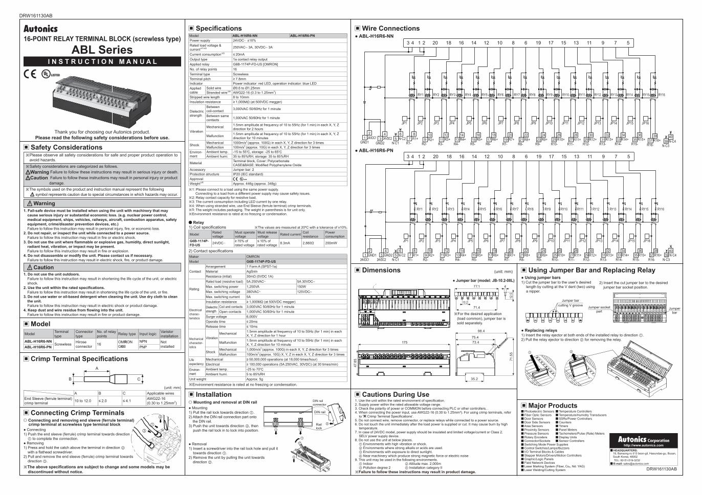
Wire Connections
Dimensions (unit: mm)
Jumper bar (model: JB-10.2-08L) Using jumper bars1) Cut the jumper bar to the user's desired
length by cutting at the V dent (two) using a nipper.
2) Insert the cut jumper bar to the desired jumper bar socket position.
※For the desired application (load common), jumper bar is sold separately.
Replacing relays1) Insert the relay ejector at both ends of the installed relay to direction ①.2) Pull the relay ejector to direction ② for removing the relay.
Jumper barcutting V groove
Using Jumper Bar and Replacing Relay
1. Use the unit within the rated environment of specification.2. Supply power within the rated allowable voltage range.3. Check the polarity of power or COMMON before connecting PLC or other controllers, .4. When connecting the power input, use AWG22-16 (0.30 to 1.25mm²). For using crimp terminals, refer
to ' Crimp Terminal Specifications'.5. Do not connect wire, remove connector, or replace relays while connected to a power source.6. Do not touch the unit immediately after the load power is supplied or cut. It may cause burn by high
temperature.7. In case of 24VDC model, power supply should be insulated and limited voltage/current or Class 2,
SELV power supply device.8. Do not use the unit at below places.
① Environments with high vibration or shock.② Environments where strong alkalis or acids are used.③ Environments with exposure to direct sunlight.④ Near machinery which produce strong magnetic force or electric noise
9. This unit may be used in the following environments.① Indoor ② Altitude max. 2,000m③ Pollution degree 2 ④ Installation category II
Cautions During Use
※Failure to follow these instructions may result in product damage.
Major Products Photoelectric Sensors Temperature Controllers Fiber Optic Sensors Temperature/Humidity Transducers Door Sensors SSRs/Power Controllers Door Side Sensors Counters Area Sensors Timers Proximity Sensors Panel Meters Pressure Sensors Tachometers/Pulse (Rate) Meters Rotary Encoders Display Units Connector/Sockets Sensor Controllers Switching Mode Power Supplies Control Switches/Lamps/Buzzers I/O Terminal Blocks & Cables Stepper Motors/Drivers/Motion Controllers Graphic/Logic Panels Field Network Devices Laser Marking System (Fiber, Co₂, Nd: YAG) Laser Welding/Cutting System
3 4 1 2
RY1
GND124VDC1 24VDC2
GND2 N.C1N.C3
R1- R3- R4- R5- R6- R7- R8- R9- R10- R11- R12- R13- R14- R15- R16-R2-R1+ R3+ R4+ R5+ R6+ R7+ R8+ R9+ R10+ R11+ R12+ R13+ R14+ R15+ R16+R2+N.C2
N.C4
JP1 JP2 JP3 JP4 JP5 JP6 JP7 JP8 JP9 JP10 JP11 JP12 JP13 JP14 JP15 JP16
RY2 RY3 RY4 RY5 RY6 RY7 RY8 RY9 RY10 RY11 RY12 RY13 RY14 RY15 RY16
20 18 16 14 12 10 19 17 15 13 11 9 7 58 6
21 3
45
67
89
1011
1213
1415
1617
1819
2021
2223
2425
2627
2829
3031
3233
3435
3637
3839
40
②
①
175
47.8
5
Jumperbar
Jumper socketpart
① ②
3 4 1 2
RY1
GND124VDC1 24VDC2
GND2N.C1 N.C3R1- R3- R4- R5- R6- R7- R8- R9- R10- R11- R12- R13- R14- R15- R16-R2-
R1+ R3+ R4+ R5+ R6+ R7+ R8+ R9+ R10+ R11+ R12+ R13+ R14+ R15+ R16+R2+N.C2 N.C4
JP1 JP2 JP3 JP4 JP5 JP6 JP7 JP8 JP9 JP10 JP11 JP12 JP13 JP14 JP15 JP16
RY2 RY3 RY4 RY5 RY6 RY7 RY8 RY9 RY10 RY11 RY12 RY13 RY14 RY15 RY16
20 18 16 14 12 10 19 17 15 13 11 9 7 58 6
21 3
45
67
89
1011
1213
1415
1617
1819
2021
2223
2425
2627
2829
3031
3233
3435
3637
3839
40
http://www.autonics.com HEADQUARTERS:18, Bansong-ro 513 beon-gil, Haeundae-gu, Busan, South Korea, 48002TEL: 82-51-519-3232
E-mail: [email protected]
DRW161130AB


![ABL Series - Autonicsautonics.se/wp-content/uploads/2018/03/a_07_abl_en_ca_aca_drw16… · ABL Series A-32 Relay Terminal Block (screwless type) [Common Feature] ... RY2 6 +24VDC](https://static.fdocuments.us/doc/165x107/5ec3c6b93d879729e3202bf1/abl-series-abl-series-a-32-relay-terminal-block-screwless-type-common-feature.jpg)


![Class 3 Ab + L AbL Review d/ dt [ AbL ] = k on [ Ab ][L] – k off [ AbL ]](https://static.fdocuments.us/doc/165x107/56815b21550346895dc8dddd/class-3-ab-l-abl-review-d-dt-abl-k-on-ab-l-k-off-abl-.jpg)