Aarti Steel WHR PDD
34
PROJECT DESIGN DOCUMENT FORM (CDM PDD) - Version 03.1. CDM – Executive Board page 1 This template shall not be altered. It shall be completed without modifying/adding headings or logo, format or font. CLEAN DEVELOPMENT MECHANISM PROJECT DESIGN DOCUMENT FORM (CDM-PDD) Version 03 - in effect as of: 28 July 2006 CONTENTS A. General description of project activity B. Application of a baseline and monitoring methodology C. Duration of the project activity / crediting period D. Environmental impacts E. Stakeholders’ comments Annexes Annex 1: Contact information on participants in the project activity Annex 2: Information regarding public funding Annex 3: Baseline information Annex 4: Monitoring plan Annex 5: Abbreviations Annex 6: References
description
qyd
Transcript of Aarti Steel WHR PDD

7/18/2019 Aarti Steel WHR PDD
http://slidepdf.com/reader/full/aarti-steel-whr-pdd 1/34
PROJECT DESIGN DOCUMENT FORM (CDM PDD) - Version 03.1.
CDM – Executive Board page 1
This template shall not be altered. It shall be completed without modifying/adding headings or logo, format or font.
CLEAN DEVELOPMENT MECHANISM
PROJECT DESIGN DOCUMENT FORM (CDM-PDD)
Version 03 - in effect as of: 28 July 2006
CONTENTS
A. General description of project activity
B. Application of a baseline and monitoring methodology
C. Duration of the project activity / crediting period
D. Environmental impacts
E. Stakeholders’ comments
Annexes
Annex 1: Contact information on participants in the project activity
Annex 2: Information regarding public funding
Annex 3: Baseline information
Annex 4: Monitoring plan
Annex 5: Abbreviations
Annex 6: References
7/18/2019 Aarti Steel WHR PDD
http://slidepdf.com/reader/full/aarti-steel-whr-pdd 2/34
PROJECT DESIGN DOCUMENT FORM (CDM PDD) - Version 03.1.
CDM – Executive Board page 2
This template shall not be altered. It shall be completed without modifying/adding headings or logo, format or font.
SECTION A. General description of project activity
A.1 Title of the project activity:
Aarti Steels Limited – Waste Heat Recovery based Captive Power Project.
Version: 01
Date: 15/05/2007
A.2. Description of the project activity:
Aarti Steels Limited (ASL) has set up an Integrated Steel Plant at Ghantikhal-Nidhipur in Athagarh
Sub division of Cuttack District, Orissa for producing sponge iron, Power, Steel Billets, Squares and
Ferro Alloys. The plant will finally produce about 0.5 Million tonnes of Value Added special steels
annually in the form of billets, squares, rounds, flats, wires, etc.
Presently the complex consists of a coal washery, Sponge Iron unit, Fluidized Bed and Waste Heat
Recovery Boilers, Steam turbine, Induction Furnace, Ladle Refining Furnace, Continuous Caster,
Ferro Alloys Plant etc. Second unit of Power plant and sponge iron plant along with Arc Furnace,
Vacuum Degassing unit, Mini Blast Furnace, Rolling Mill, Wire Drawing Mill will be added in
immediate future.
The ASL Sponge Iron unit at present consists of one rotary kiln of 500 tons per day (TPD). The
generation of flue gas from the kiln is about 120,000 Nm3 /hr at 950-1000
0C. The rotary kiln is directly
connected to the waste heat recovery boiler (WHRB), with steam generation capacity of 52 TPH which
is the project activity. The total waste flue gas generated is ducted to the WHRB to generate steam at 87
Kg/Cm2 and 510
0C.
Flue gas with high heat content is generated in the Rotary kiln in the Sponge iron plant during
conversion of Iron Ore into Sponge Iron. The entire gas coming out from after burning chamber
(ABC) of the Direct Reduced Iron (DRI) plant at about 950-10000C is passed through the Waste
Heat Recovery Boiler (WHRB). The volume of the gas generated is proportionate to the production
of the DRI kiln. The boiler absorbs the sensible heat of gas and cooled gas at about 160 0C is passed
through electrostatic precipitator (ESP) and subsequently vented to the atmosphere. The kiln when
operating at full capacity can generate adequate waste gas to produce steam up to 52 TPH equivalent
to 12 MW of power. The total power generated for the complex is about 40 MW, out which about 12
MW is generated by the WHR power plant and the balance power by coal and coal washery rejects
based Atmospheric Fluidised Bed Combustion (AFBC) power plant. In exigency cases, power from
the grid is also imported. The 12 MW electricity generated by the WHR power plant displaces
electricity that would have otherwise been generated by a coal and coal washery rejects based captivepower plant.
The purpose of the project activity is to generate power through WHRB to partially meet the in-house
requirements of ASL or export the surplus power to the Orissa State Grid
7/18/2019 Aarti Steel WHR PDD
http://slidepdf.com/reader/full/aarti-steel-whr-pdd 3/34
PROJECT DESIGN DOCUMENT FORM (CDM PDD) - Version 03.1.
CDM – Executive Board page 3
This template shall not be altered. It shall be completed without modifying/adding headings or logo, format or font.
Project’s contribution to sustainable development
The project activity has contributed to ‘Sustainable Development of India’ because the project activity is
generating power using waste heat gases from the process. By generating clean power, ASL has replacedpower generation from a coal and coal washery rejects based unit. Therefore, the project activity enables
reduction in CO2 emissions and saves the conventional fuel.
The project imparts a direct positive impact by improvement of quality of life of local people by
providing inflow of funds, direct employment, indirect job generation, technological & managerial
capacity building etc. The following paragraphs illustrate briefly how the project activity contributes to
the four pillars (indicators) of sustainable development of India:
Social aspects
The location of the project in rural setting contributes towards poverty alleviation by generating both
direct and indirect employment.
Economic aspects
The project’s initial investment is to the tune of INR 2762.4 Million in addition to which there will be
continuous inflow of funds considering CDM revenues. In the absence of the project such an inflow of
funds to the region was not envisaged. The project will also earn additional revenue to the local and
central government.
Environmental aspects
Majority of the power generation in the country is from the fossil fuels like coal, oil and gas. However,
the project activity generates the electricity from the waste flue gas and thereby reduces the GHG
emissions. The project activity utilizes the enthalpy of the hot flue gas, which will protect the
environment from thermal pollution.
Technological aspects
The Captive Power Plant (CPP) is based on the WHR technology, a clean technology for power
generation from waste hot flue gas, which would otherwise be vented to the atmosphere. The project
comprises of 52 tons per hour (TPH) capacity boiler with the outlet steam parameters of 87 kg/cm2 and
510º C.
A.3. Project participants:
Name of Party involved
(host indicates a host Party)
Private and/or public entity
(ies) project participants
(as applicable)
Kindly indicate if the Party
involved wishes to be
considered as project
participant
(Yes/No)
India Aarti Steels Limited No
7/18/2019 Aarti Steel WHR PDD
http://slidepdf.com/reader/full/aarti-steel-whr-pdd 4/34
PROJECT DESIGN DOCUMENT FORM (CDM PDD) - Version 03.1.
CDM – Executive Board page 4
This template shall not be altered. It shall be completed without modifying/adding headings or logo, format or font.
A.4. Technical description of the project activity:
A.4.1. Location of the project activity:
A.4.1.1. Host Party(ies):
India
A.4.1.2. Region/State/Province etc.:
Orissa
A.4.1.3. City/Town/Community etc:
Ghantikhal, P.O. Mahakalabasta, Via. Athagarh, District Cuttack,
A.4.1.4. Detail of physical location, including information allowing the
unique identification of this project activity (maximum one page):
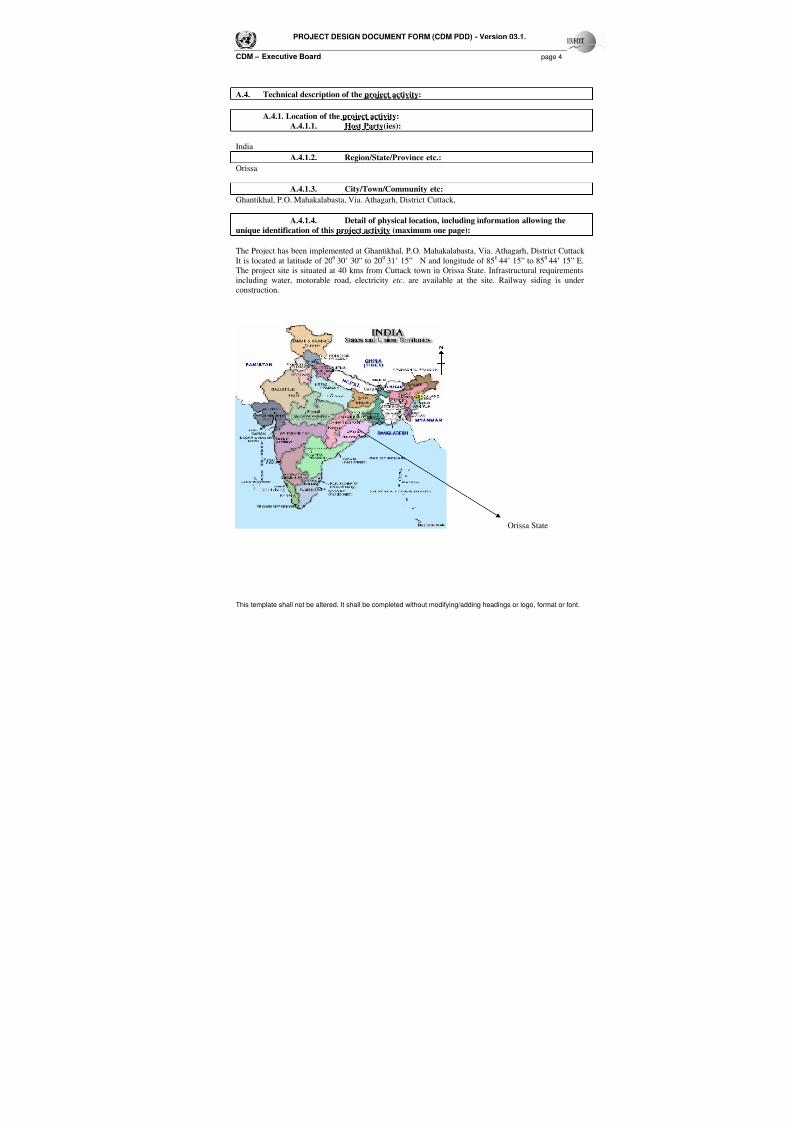
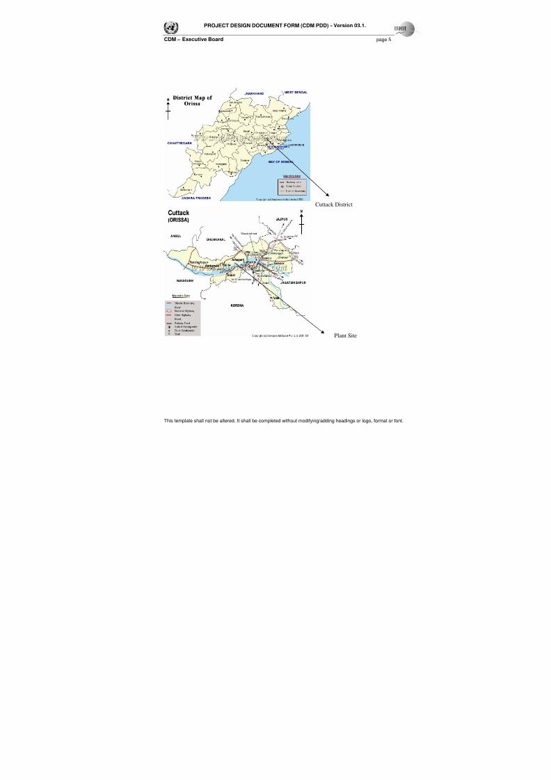
The Project has been implemented at Ghantikhal, P.O. Mahakalabasta, Via. Athagarh, District Cuttack
It is located at latitude of 200
30’ 30” to 200
31’ 15” N and longitude of 850
44’ 15” to 850
44’ 15” E.
The project site is situated at 40 kms from Cuttack town in Orissa State. Infrastructural requirements
including water, motorable road, electricity etc. are available at the site. Railway siding is under
construction.
Orissa State
7/18/2019 Aarti Steel WHR PDD
http://slidepdf.com/reader/full/aarti-steel-whr-pdd 5/34
PROJECT DESIGN DOCUMENT FORM (CDM PDD) - Version 03.1.
CDM – Executive Board page 5
This template shall not be altered. It shall be completed without modifying/adding headings or logo, format or font.
Cuttack District
Plant Site

7/18/2019 Aarti Steel WHR PDD
http://slidepdf.com/reader/full/aarti-steel-whr-pdd 6/34
PROJECT DESIGN DOCUMENT FORM (CDM PDD) - Version 03.1.
CDM – Executive Board page 6
This template shall not be altered. It shall be completed without modifying/adding headings or logo, format or font.
A.4.2. Category(ies) of project activity:
The project activity is generating electricity from the waste hot gas generated from the sponge iron plant. It
comes under category 1: Energy Industries (renewable/non renewable sources) as per “List of SectoralScopes”, Version 04. The methodology used for this project activity is ‘Approved Consolidated Baseline
Methodology - ACM0004:
Version: 02
Date : 03 March 2006
A.4.3. Technology to be employed by the project activity:
ASL integrated complex consists of facilities amongst others are one AFBC and one WHRB boiler. The
WHRB is a single drum water tube boiler of 52 TPH capacity operating at 87 ata and at a temperature of
5100C. The Power generated from the generator at 11 kV is connected to other units after the auxiliary
power consumption of WHR power plant. The technology used for this project activity is based on
Rankine cycle technology.
The ASL Sponge Iron unit consists of one rotary kiln of 500 TPD. The generation of flue gas from the
kiln at full capacity is 120,000 Nm3 /hr at 950-1000
0C. The rotary kiln is directly connected to the
WHRB Boiler, with a steam generation capacity of 52 TPH. The total waste flue gas generated is ducted
to the WHRB to generate steam at 87 kg/cm2 and 510
0C.
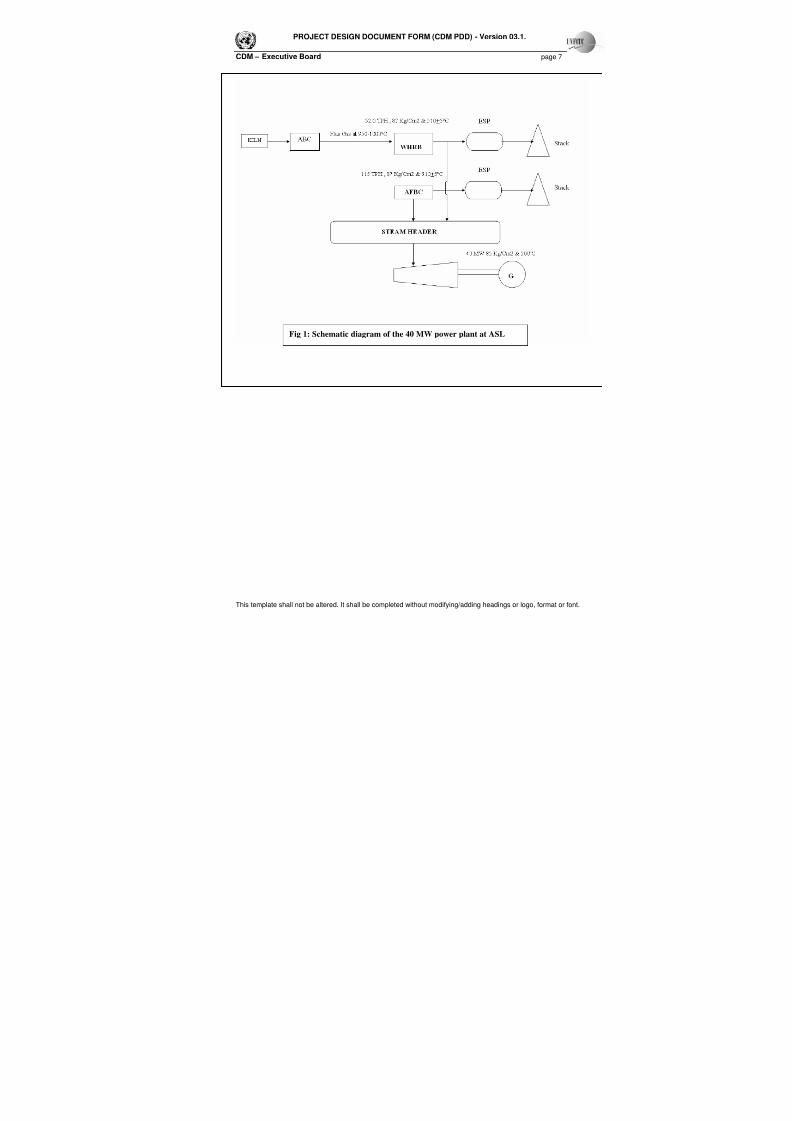
The generated steam is then introduced in to the Single flow with downward exhaust condensing Turbo
Generator for power generation. After transferring the heat, the waste flue gas is passed through the
Electro Static Precipitator (ESP) and vented to atmosphere. Fig 1 shows the schematic diagram of the 40
MW power plant at ASL.
Equipment Technical Details
Sr. No Parameter DetailsA. Turbine
1. Make ALSTOM Power Turbine
presently known as Siemens Ltd.
2. Type Single flow with downward
exhaust condensing
3. Rating 40 MW
4. Inlet steam pressure 85 kg/cm2
5. Inlet steam temperature 5000C
6. Turbine Speed 7059 rpm
B. Boiler Make-Cethar Vessels Limited.
7. Type Single drum water tube boiler
8. Net Steaming Capacity at MCR 52 TPH9. Super heater outlet pressure 87 kg/cm2
10. Super heater outlet temperature 5100C
11. Gas temperature 950-10000C
7/18/2019 Aarti Steel WHR PDD
http://slidepdf.com/reader/full/aarti-steel-whr-pdd 7/34
PROJECT DESIGN DOCUMENT FORM (CDM PDD) - Version 03.1.
CDM – Executive Board page 7
This template shall not be altered. It shall be completed without modifying/adding headings or logo, format or font.
Fig 1: Schematic diagram of the 40 MW power plant at ASL
7/18/2019 Aarti Steel WHR PDD
http://slidepdf.com/reader/full/aarti-steel-whr-pdd 8/34
PROJECT DESIGN DOCUMENT FORM (CDM PDD) - Version 03.1.
CDM – Executive Board page 8
This template shall not be altered. It shall be completed without modifying/adding headings or logo, format or font.
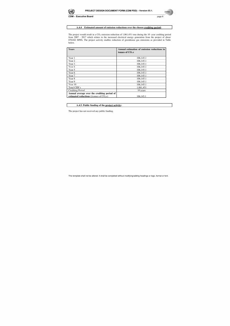
A.4.4 Estimated amount of emission reductions over the chosen crediting period:
The project would result in a CO2 emission reduction of 1,061,451 tons during the 10 -year crediting periodfrom 2007 - 2017 which relates to the increased electrical energy generation from the project of about
870,042 MWh. The project activity enables reduction of greenhouse gas emissions as provided in Table
below.
Years Annual estimation of emission reductions in
tonnes of CO2 e
Year 1 106,145.1
Year 2 106,145.1
Year 3 106,145.1
Year 4 106,145.1
Year 5 106,145.1
Year 6 106,145.1
Year 7 106,145.1
Year 8 106,145.1
Year 9 106,145.1
Year 10 106,145.1
Total CER’s 1,061,451
Crediting Period 10 years
Annual average over the crediting period of
estimated reductions ((tonnes of CO2 e) 106,145.1
A.4.5. Public funding of the project activity:
The project has not received any public funding.
7/18/2019 Aarti Steel WHR PDD
http://slidepdf.com/reader/full/aarti-steel-whr-pdd 9/34
PROJECT DESIGN DOCUMENT FORM (CDM PDD) - Version 03.1.
CDM – Executive Board page 9
This template shall not be altered. It shall be completed without modifying/adding headings or logo, format or font.
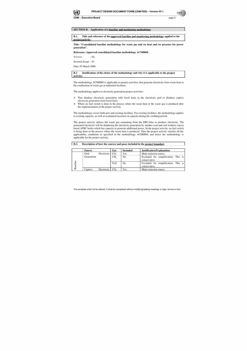
SECTION B. Application of a baseline and monitoring methodology
B.1. Title and reference of the approved baseline and monitoring methodology applied to the
project activity:
Title: “Consolidated baseline methodology for waste gas and /or heat and /or pressure for power
generation”.
Reference: Approved consolidated baseline methodology ACM0004.
Version : 02,
Sectoral Scope : 01
Date: 03 March 2006
B.2 Justification of the choice of the methodology and why it is applicable to the project
activity:
The methodology ACM0004 is applicable to project activities that generate electricity from waste heat or
the combustion of waste gas in industrial facilities.
The methodology applies to electricity generation project activities:
That displace electricity generation with fossil fuels in the electricity grid or displace captive
electricity generation from fossil fuels;
Where no fuel switch is done in the process where the waste heat or the waste gas is produced after
the implementation of the project activity
The methodology covers both new and existing facilities. For existing facilities, the methodology applies
to existing capacity, as well as to planned increases in capacity during the crediting period.
The project activity utilizes the waste gas emanating from the DRI kilns to produce electricity. The
generated electricity will be displacing the electricity generation by another coal and coal washery rejects
based AFBC boiler which has capacity to generate additional power. In the project activity, no fuel switch
is being done in the process where the waste heat is produced. Thus the project activity satisfies all the
applicability conditions as specified in the methodology ACM0004, and hence the methodology is
applicable for the project activity.
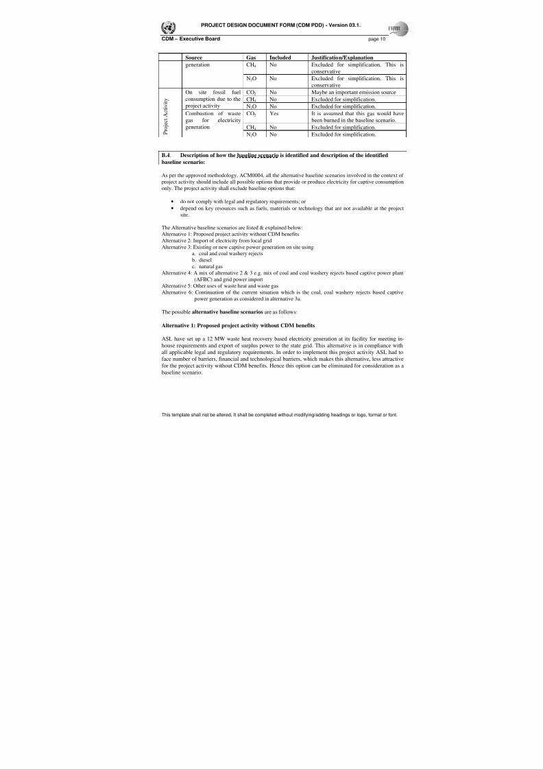
B.3. Description of how the sources and gases included in the project boundary
Source Gas Included Justification/Explanation
CO2 Yes Main emission sourceCH4 No Excluded for simplification. This is
conservative
Grid ElectricityGeneration
N2O No Excluded for simplification. This is
conservative B a s e l i n e
Captive Electricity CO2 Yes Main emission source
7/18/2019 Aarti Steel WHR PDD
http://slidepdf.com/reader/full/aarti-steel-whr-pdd 10/34
PROJECT DESIGN DOCUMENT FORM (CDM PDD) - Version 03.1.
CDM – Executive Board page 10
This template shall not be altered. It shall be completed without modifying/adding headings or logo, format or font.
Source Gas Included Justification/Explanation
CH4 No Excluded for simplification. This is
conservative
generation
N2O No Excluded for simplification. This is
conservativeCO2 No Maybe an important emission source
CH4 No Excluded for simplification.
On site fossil fuel
consumption due to the
project activity N2O No Excluded for simplification.
CO2 Yes It is assumed that this gas would have
been burned in the baseline scenario.
CH4 No Excluded for simplification. P r o j e c t A c t i v i t y
Combustion of waste
gas for electricity
generation
N2O No Excluded for simplification.
B.4. Description of how the baseline scenario is identified and description of the identified
baseline scenario:
As per the approved methodology, ACM0004, all the alternative baseline scenarios involved in the context of
project activity should include all possible options that provide or produce electricity for captive consumption
only. The project activity shall exclude baseline options that:
• do not comply with legal and regulatory requirements; or
• depend on key resources such as fuels, materials or technology that are not available at the project
site.
The Alternative baseline scenarios are listed & explained below:
Alternative 1: Proposed project activity without CDM benefits
Alternative 2: Import of electricity from local grid
Alternative 3: Existing or new captive power generation on site using
a. coal and coal washery rejectsb. diesel
c. natural gas
Alternative 4: A mix of alternative 2 & 3 e.g. mix of coal and coal washery rejects based captive power plant
(AFBC) and grid power import
Alternative 5: Other uses of waste heat and waste gas
Alternative 6: Continuation of the current situation which is the coal, coal washery rejects based captive
power generation as considered in alternative 3a.
The possible alternative baseline scenarios are as follows:
Alternative 1: Proposed project activity without CDM benefits
ASL have set up a 12 MW waste heat recovery based electricity generation at its facility for meeting in-
house requirements and export of surplus power to the state grid. This alternative is in compliance with
all applicable legal and regulatory requirements. In order to implement this project activity ASL had to
face number of barriers, financial and technological barriers, which makes this alternative, less attractive
for the project activity without CDM benefits. Hence this option can be eliminated for consideration as a
baseline scenario.
7/18/2019 Aarti Steel WHR PDD
http://slidepdf.com/reader/full/aarti-steel-whr-pdd 11/34
PROJECT DESIGN DOCUMENT FORM (CDM PDD) - Version 03.1.
CDM – Executive Board page 11
This template shall not be altered. It shall be completed without modifying/adding headings or logo, format or font.
Alternative 2: Import of electricity from Eastern regional grid
In the absence of the CDM project activity, ASL would have imported electricity from the Eastern
regional grid, which will further lead to GHG emissions from fossil fuel based thermal power plants.
This alternative is in compliance with all applicable legal and regulatory requirements and may be a partof the baseline.
Alternative 3a: Coal and coal washery rejects based captive power generation
In the absence of the proposed CDM Project activity, ASL could generate electricity by implementing a
coal and coal washery rejects based CPP to meet their demand. A coal, coal washery rejects based CPP
would be meeting the requirement of the project participant as the company is already operating one
AFBC boiler using coal, coal washery rejects from their existing washeries. Additional power generation
of 12 MW (equivalent to the capacity of the project activity i.e. the WHRB) could have been achieved
with a marginal increase in cost of FBC boiler. Another AFBC boiler with coal and coal washery rejects
would also have had technological advantages of higher PLF and also abundant availability of fuel from
their existing and nearby coal washeries resulting in lesser capital cost and cost of generation per unit.
This alternative is in compliance with all applicable legal and regulatory requirements and may be a part
of the baseline.
Alternative 3b: Diesel based captive power generation
In the absence of the proposed CDM Project activity, ASL could generate power by implementing a
diesel-based power plant to meet their power demand. This will lead to emission of GHG gases, by the
diesel based captive power generation. This alternative is in compliance with all applicable legal and
regulatory requirements and may be a part of the baseline.
Alternative 3c: Gas based captive power generation
ASL could generate its own power using natural gas based captive power plant. Although this alternative
is in compliance with all regulatory and legal requirements, it is not a realistic alternative due to non
availability of natural gas distribution network in Orissa. Therefore, alternative 3c may be excluded from
baseline scenario.
Alternative 4: Mix of options (2) and (3) – Grid power plus captive power based on coal, coal washery
rejects, diesel or gas
ASL has the option of satisfying its captive power requirements using grid power as well as generating captive
power from other fuels such as coal and coal washery rejects, diesel or gas. This alternative is in compliance
with the existing legal and regulatory requirements. However ASL already has an existing AFBC boiler based
on coal and coal washery wastes, it makes economic sense for them to go for this coal/ coal washery waste
based CPP only rather than the combination of two (grid power and CPP). Therefore this option is ruled outfor further consideration. Therefore the options 2, 3a and 3b are most likely when compared to option 4.
Alternative - 5 Other uses of waste heat and waste gas
Since there is practically no other use of waste gases (emanating from the kiln) in the steel plant, in
absence of the proposed project the waste gas thus generated would have been flared into the atmosphere
7/18/2019 Aarti Steel WHR PDD
http://slidepdf.com/reader/full/aarti-steel-whr-pdd 12/34
PROJECT DESIGN DOCUMENT FORM (CDM PDD) - Version 03.1.
CDM – Executive Board page 12
This template shall not be altered. It shall be completed without modifying/adding headings or logo, format or font.
leading to air pollution which would be the continuation of prevailing practice. Hence this alternative is
excluded from consideration.
Evaluation of alternatives for baseline selection:
Among the five alternatives discussed above that could be a part of baseline scenario, to select the
appropriate baseline scenario, the alternatives have been discussed below:
Among all these alternatives, the one that does not face any prohibitive barrier and is the most
economically attractive should be considered as the baseline scenario. Thus from the above identified
alternatives, it can be found that alternatives 2, 3a & 3b are the most likely alternatives for the baseline
scenario.
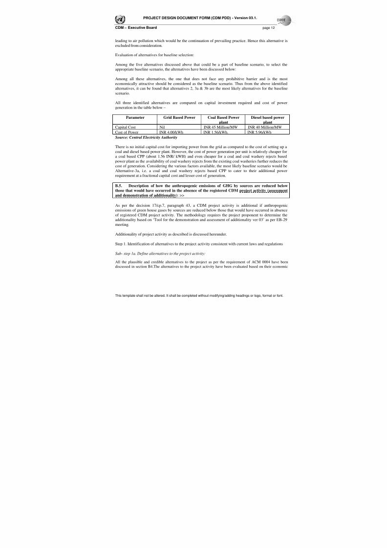
All three identified alternatives are compared on capital investment required and cost of power
generation in the table below –
Parameter Grid Based Power Coal Based Power
plant
Diesel based power
plant
Capital Cost Nil INR 45 Million/MW INR 40 Million/MW
Cost of Power INR 4.00/kWh INR 1.56/kWh. INR 5.96/kWh
Source: Central Electricity Authority
There is no initial capital cost for importing power from the grid as compared to the cost of setting up a
coal and diesel based power plant. However, the cost of power generation per unit is relatively cheaper for
a coal based CPP (about 1.56 INR/ kWH) and even cheaper for a coal and coal washery rejects based
power plant as the availability of coal washery rejects from the existing coal washeries further reduces the
cost of generation. Considering the various factors available, the most likely baseline scenario would be
Alternative-3a, i.e. a coal and coal washery rejects based CPP to cater to their additional power
requirement at a fractional capital cost and lesser cost of generation.
B.5. Description of how the anthropogenic emissions of GHG by sources are reduced below
those that would have occurred in the absence of the registered CDM project activity (assessment
and demonstration of additionality): >>
As per the decision 17/cp.7, paragraph 43, a CDM project activity is additional if anthropogenic
emissions of green house gases by sources are reduced below those that would have occurred in absence
of registered CDM project activity. The methodology requires the project proponent to determine the
additionality based on ‘Tool for the demonstration and assessment of additionality ver 03’ as per EB-29
meeting.
Additionality of project activity as described is discussed hereunder.
Step 1. Identification of alternatives to the project activity consistent with current laws and regulations
Sub- step 1a. Define alternatives to the project activity:
All the plausible and credible alternatives to the project as per the requirement of ACM 0004 have been
discussed in section B4.The alternatives to the project activity have been evaluated based on their economic

7/18/2019 Aarti Steel WHR PDD
http://slidepdf.com/reader/full/aarti-steel-whr-pdd 13/34
PROJECT DESIGN DOCUMENT FORM (CDM PDD) - Version 03.1.
CDM – Executive Board page 13
This template shall not be altered. It shall be completed without modifying/adding headings or logo, format or font.
attractiveness and hence a coal and coal washery rejects based AFBC boiler is considered as the alternative
source of power in absence of the project activity.
Sub-step 1b
Consistency with mandatory applicable laws and regulations
The alternatives discussed in section B4 are all in compliance with applicable legal and regulatory
requirements. Moreover, there are no foreseeable regulatory changes that would make the above alternatives
non- compliant.
The project proponent has opted for Step-3 i.e. barrier analysis
Step-3. Barrier Analysis
Sub-step 3a: Identify barriers that would prevent the implementation of the proposed CDM project
activity:
Investment Barrier
ASL has installed an AFBC boiler at 115 TPH for their captive power generation which would cater to
their power requirement of 28 MW. In order to meet the additional power requirement of 12 MW, ASL
could have set up another AFBC boiler of this capacity as it requires marginal increase in the project cost.
However, ASL in order to reduce the GHG emissions and also to avail the carbon benefits due to power
generation from WHRB, proposed to set up a WHRB with 52 TPH capacity
The cost of setting up a WHRB of this high pressure and temperature configuration is much higher as
compared to setting up another small AFBC boiler or augmenting the existing capacity. The company has
installed one boiler based on waste heat recovery and steam piping which is at additional cost as
compared to only up-gradation of coal and coal washery rejects based FBC Boiler to generate the balance
steam. The cost of adding this additional steam generation capacity would have been marginal ascompared to setting up of WHRB for power generation.
Comparing with similar projects, it can be noted that ASL is the second in the region to implement a
WHRB boiler with high pressure and temperature configuration of 87 ata and 510 deg C respectively
which requires greater investment when compared to other WHRB configuration (<67 ata pressure)
already implemented in the sector.
Technological barriers
The operation of the Kiln and the WHRB are interrelated without any isolation mechanism i.e. the kiln
cannot run without the WHRB in operation and the entire gases generated from the kiln are routed
through WHRB. Any instability in the quality of raw material of the DRI kiln, affects the flue gasesgenerated. Usually the hot waste gases coming out of the kiln contain high level of SOx and NOx and
hence the temperature needs to be maintained at a certain level (above acid dew point) so as to prevent
formation of corrosive acids due to condensation of these gases. Corrosive acids may lead to acute
damage in the boiler due to boiler tube failure and subsequently in the down stream equipments like ESP,
ID Fan, dampers and the exhaust stack and hence boilers are to be taken to shut down for maintenance
and kiln also has to be stopped. The cooling and heating cycle of the kiln takes minimum of about 5-6
7/18/2019 Aarti Steel WHR PDD
http://slidepdf.com/reader/full/aarti-steel-whr-pdd 14/34
PROJECT DESIGN DOCUMENT FORM (CDM PDD) - Version 03.1.
CDM – Executive Board page 14
This template shall not be altered. It shall be completed without modifying/adding headings or logo, format or font.
days involving a substantial expenditure. Also, off grade sponge iron generation takes place in the kiln
while cooling and restarting it. Moreover such irregularities in boiler operation also hamper smooth
functioning of electric furnaces. Thus all these technical difficulties lead to colossal operational barriers
which need to be properly addressed to ensure smooth functioning of the unit. Whereas all these technical
barriers do not appear for other alternatives discussed above in section B.4.
The quantum of generation of power from WHRB depends on the quantum of gas generated from the kiln
which in turn depends on the production of sponge iron. Kiln always does not run at rated capacity which
leads to shortfall in power generation leading to financial loss.
For ensuring continuous power generation consistent supply of gas at requisite heat value to the WHRB
is required. This would require proven technology and trained manpower to operate such kind of system.
As ASL had no prior experience in this sector, it had to face many technological barriers during and after
commissioning of the plant. ASL was aware that they would have to get people trained to operate and
maintain the system for ensuring consistent and reliable power generation through the waste heat recovery
from the DRI kilns without adversely affecting the kiln operation and product quality. However, to sort
out the problems associated with operating WHRB at high pressure (87ata) and 5100C temperature, ASL
had to shut down the kiln many a times leading to huge financial loss to the tune of INR 135 Million. The
other production units of the plant could also not be run due to non-availability of power. The details of
various technological barriers faced by ASL and the subsequent financial loss due to it will be given to
the DOE during the validation.
Any disruption in the operation of the pollution control equipment like ESP or any other down stream
auxiliaries will lead to boiler failure and hence the operation of the DRI kiln also will be disrupted due to
interconnectivity of the kiln with the boiler without any isolation scheme. Thus it demands exact
functioning of all the down stream equipments so as to ensure hassle free operation in all the production
facilities.
A fully condensing turbine has been installed so as to maximise the electrical output. Besides this an
economiser also has been set to operation with an aim to maintain lowest possible exhaust gastemperature which will enable maximum heat recovery from the waste gases. Thus designing of the
economiser demands additional technical sophistication so as to ensure gas temperature is maintained
above acid dew point before the gas leaves through the exhaust stack.
The identified project is connected with the state grid. Synchronisation with the grid leads to more
disturbances since the state grid is very much susceptible to problems like voltage fluctuation, regular
frequency variation etc. Therefore to manage with all these adversities high voltage protection relays have
been employed. These relays are again linked to the main DCS of the plant for extensive monitoring with
an arrangement of rapid connection and disconnection with the grid as and when required.
Despite all the above technical barriers ASL has opted for WHRB considering the flow of CDM revenues.
Barriers due to prevailing practice
ASL was the 2nd
company1 in the state to initiate the work on its plant and signed a Memorandum of
Understanding (MOU) with the Orissa Government. Though, ASL had initiated the work of setting up
the integrated complex earlier, it could not do so in time, as it faced many barriers during the
1 Pioneer special MOU-Orissa (mines and Minerals)
7/18/2019 Aarti Steel WHR PDD
http://slidepdf.com/reader/full/aarti-steel-whr-pdd 15/34
PROJECT DESIGN DOCUMENT FORM (CDM PDD) - Version 03.1.
CDM – Executive Board page 15
This template shall not be altered. It shall be completed without modifying/adding headings or logo, format or font.
implementation of the project. ASL was amongst the first companies to set up the WHRB at high
operating parameters (i.e. 87 ata).
Institutional Barrier
ASL has signed a power purchase agreement (PPA) with Grid Corporation of Orissa (GRIDCO) forexporting power to the grid. GRIDCO has signed the PPA for a tariff of INR 2.02 for the whole tenure of
the PPA. Also, as per the PPA, GRIDCO has to pay ASL for the power exported within seven days of the
receipt of the invoice. However, there have been consistent delays in payment from GRIDCO. This has
led to further financial constraints to ASL. Carbon funds i.e. CDM revenues, will ease out these financial
constraints.
Sub-step 3 b. Show that the identified barriers would not prevent the implementation of at least one of
the alternatives (except the proposed project activity):
The above identified barriers do not prevent the implementation of the baseline option i.e. the coal/ coal
washery reject based captive power plant which is the most likely and economically attractive alternative
to the project. This is considering the below:
(1) The capital cost of the coal based CPP is lower when compared to the project activity (WHRB
based power with high pressure and temperature configuration).
(2) The AFBC technology is proven and, therefore does not face technology related barriers as
compared to a WHRB system of high temperature pressure configuration (as described in the
Technological barriers section in Sub-step 3a).
Step 4. Common practice analysis
Based on the information about activities similar to the proposed project activity, ASL need to
demonstrate a common practice analysis to complement and reinforce the barrier analysis. ASL is
required to identify and discuss the existing common practice through the following sub-steps:
Step 4a: Analyze other activities similar to the proposed project activity
A recent study conducted by Joint Plant Committee under the guidance of Ministry of Steel, Government
of India pinpoints that out of 147 coal based sponge iron units surveyed the number of units with captive
power generation facility is only 16 with maximum concentration in Chhattisgarh. Thus it clearly
indicates that captive power generation is not a common phenomenon in the similar industrial units.
Captive power generation includes waste heat recovery based power generation as well.
In addition to that ASL has pioneered adopting SL/RN technology of Lurgie, GmbH, West Germany in
the region as they are the second of its kind to initiate the work to set up the project. The technology
differs with regard to two operations viz. feeding/blowing coal and introduction of air for the process.
This technology would ensure flue gas quantity and quality resulting in to stable power generation.
Such an advanced technology based WHR power generation unit has been employed in only one unit in
Orissa prior to ASL. Thus in light of the above discussion it can be concluded that difficulties associated
with such kind of project activities has restricted other similar industrial units from establishing such a
project where as ASL has gone ahead with the proposed project activity considering CDM revenue into
account.
7/18/2019 Aarti Steel WHR PDD
http://slidepdf.com/reader/full/aarti-steel-whr-pdd 16/34
PROJECT DESIGN DOCUMENT FORM (CDM PDD) - Version 03.1.
CDM – Executive Board page 16
This template shall not be altered. It shall be completed without modifying/adding headings or logo, format or font.
Step 4b: Discuss any similar options that are occurring
Thus in view of the above discussion it can be concluded that the project activity is not a common
practice amongst similar industrial units in the region and hence the project facility has opted for the
proposed project only after taking CDM funding into consideration.
B.6. Emission reductions:
B.6.1. Explanation of methodological choices:
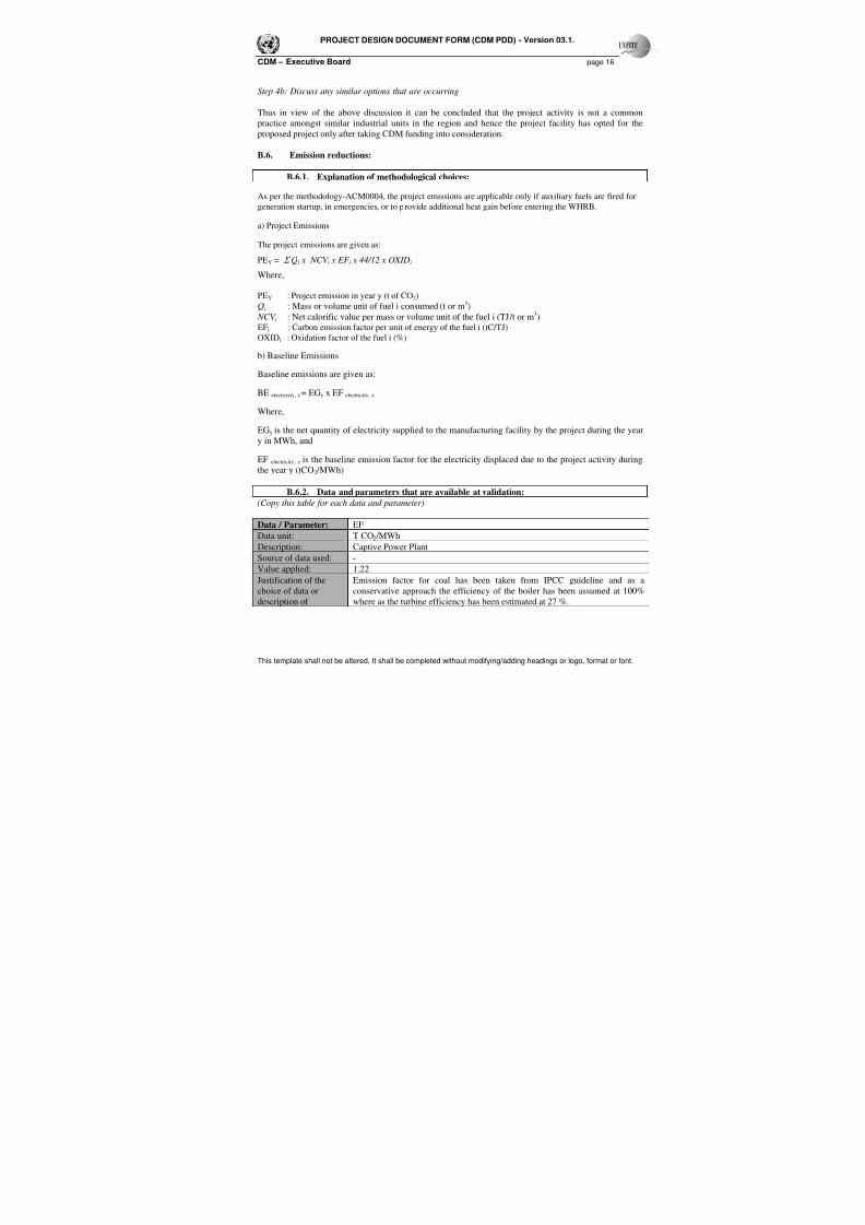
As per the methodology-ACM0004, the project emissions are applicable only if auxiliary fuels are fired for
generation startup, in emergencies, or to provide additional heat gain before entering the WHRB.
a) Project Emissions
The project emissions are given as:
PEY = Σ Qi x NCV i x EF i x 44/12 x OXIDi
Where,
PEY : Project emission in year y (t of CO2)
Qi : Mass or volume unit of fuel i consumed (t or m3)
NCV i : Net calorific value per mass or volume unit of the fuel i (TJ/t or m3)
EFi : Carbon emission factor per unit of energy of the fuel i (tC/TJ)
OXIDi : Oxidation factor of the fuel i (%)
b) Baseline Emissions
Baseline emissions are given as:
BE electricity, y = EGy x EF electricity, y
Where,
EGy is the net quantity of electricity supplied to the manufacturing facility by the project during the year
y in MWh, and
EF electricity, y is the baseline emission factor for the electricity displaced due to the project activity during
the year y (tCO2 /MWh)
B.6.2. Data and parameters that are available at validation:
(Copy this table for each data and parameter)
Data / Parameter: EF
Data unit: T CO2 /MWhDescription: Captive Power Plant
Source of data used: -
Value applied: 1.22
Justification of the
choice of data or
description of
Emission factor for coal has been taken from IPCC guideline and as a
conservative approach the efficiency of the boiler has been assumed at 100%
where as the turbine efficiency has been estimated at 27 %.
7/18/2019 Aarti Steel WHR PDD
http://slidepdf.com/reader/full/aarti-steel-whr-pdd 17/34
PROJECT DESIGN DOCUMENT FORM (CDM PDD) - Version 03.1.
CDM – Executive Board page 17
This template shall not be altered. It shall be completed without modifying/adding headings or logo, format or font.
measurement methods
and procedures
actually applied :
Any comment: This data has been calculated and the details are given in Annex – 3
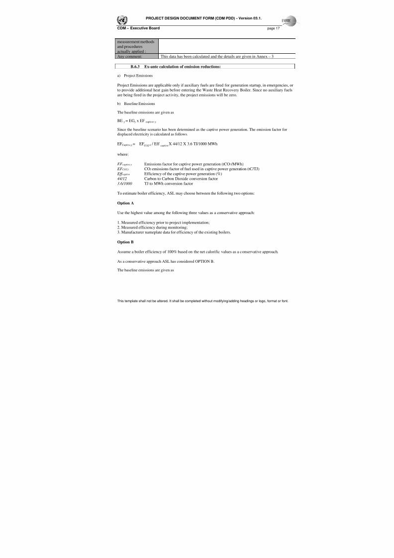
B.6.3 Ex-ante calculation of emission reductions:
a) Project Emissions
Project Emissions are applicable only if auxiliary fuels are fired for generation startup, in emergencies, or
to provide additional heat gain before entering the Waste Heat Recovery Boiler. Since no auxiliary fuels
are being fired in the project activity, the project emissions will be zero.
b) Baseline Emissions
The baseline emissions are given as
BE y = EGy x EF captive, y
Since the baseline scenario has been determined as the captive power generation. The emission factor for
displaced electricity is calculated as follows.
EFCaptive,y = EFCO2
,i / Effcaptive
X 44/12 X 3.6 TJ/1000 MWh
where:
EF captive,y Emissions factor for captive power generation (tCO2 /MWh)
EF CO2,i CO2 emissions factor of fuel used in captive power generation (tC/TJ)
Eff captive Efficiency of the captive power generation (%)
44/12 Carbon to Carbon Dioxide conversion factor
3.6/1000 TJ to MWh conversion factor
To estimate boiler efficiency, ASL may choose between the following two options:
Option A
Use the highest value among the following three values as a conservative approach:
1. Measured efficiency prior to project implementation;
2. Measured efficiency during monitoring;
3. Manufacturer nameplate data for efficiency of the existing boilers.
Option B
Assume a boiler efficiency of 100% based on the net calorific values as a conservative approach.
As a conservative approach ASL has considered OPTION B.
The baseline emissions are given as
7/18/2019 Aarti Steel WHR PDD
http://slidepdf.com/reader/full/aarti-steel-whr-pdd 18/34
PROJECT DESIGN DOCUMENT FORM (CDM PDD) - Version 03.1.
CDM – Executive Board page 18
This template shall not be altered. It shall be completed without modifying/adding headings or logo, format or font.
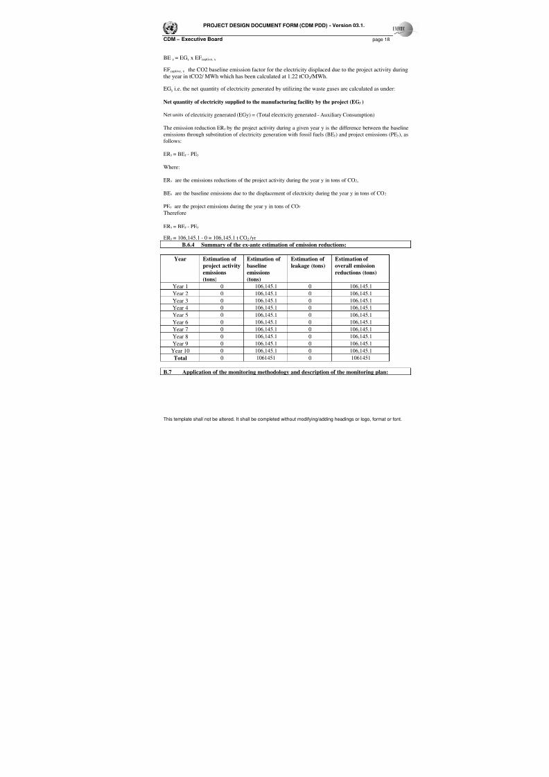
BE y = EGy x EFcaptive, y
EFcaptive, y the CO2 baseline emission factor for the electricity displaced due to the project activity during
the year in tCO2/ MWh which has been calculated at 1.22 tCO2 /MWh.
EGy i.e. the net quantity of electricity generated by utilizing the waste gases are calculated as under:
Net quantity of electricity supplied to the manufacturing facility by the project (EGy )
Net units of electricity generated (EGy) = (Total electricity generated - Auxiliary Consumption)
The emission reduction ERy by the project activity during a given year y is the difference between the baseline
emissions through substitution of electricity generation with fossil fuels (BEy) and project emissions (PEy), as
follows:
ERy = BEy - PEy
Where:
ERy are the emissions reductions of the project activity during the year y in tons of CO2,
BEy are the baseline emissions due to the displacement of electricity during the year y in tons of CO 2
PEy are the project emissions during the year y in tons of CO2
Therefore
ERy = BEy - PEy
ERy = 106,145.1 - 0 = 106,145.1 t CO2 /yr
B.6.4 Summary of the ex-ante estimation of emission reductions:
Year Estimation of
project activity
emissions
(tons)
Estimation of
baseline
emissions
(tons)
Estimation of
leakage (tons)
Estimation of
overall emission
reductions (tons)
Year 1 0 106,145.1 0 106,145.1
Year 2 0 106,145.1 0 106,145.1
Year 3 0 106,145.1 0 106,145.1
Year 4 0 106,145.1 0 106,145.1
Year 5 0 106,145.1 0 106,145.1
Year 6 0 106,145.1 0 106,145.1
Year 7 0 106,145.1 0 106,145.1
Year 8 0 106,145.1 0 106,145.1
Year 9 0 106,145.1 0 106,145.1
Year 10 0 106,145.1 0 106,145.1
Total 0 1061451 0 1061451
B.7 Application of the monitoring methodology and description of the monitoring plan:
7/18/2019 Aarti Steel WHR PDD
http://slidepdf.com/reader/full/aarti-steel-whr-pdd 19/34
PROJECT DESIGN DOCUMENT FORM (CDM PDD) - Version 03.1.
CDM – Executive Board page 19
This template shall not be altered. It shall be completed without modifying/adding headings or logo, format or font.
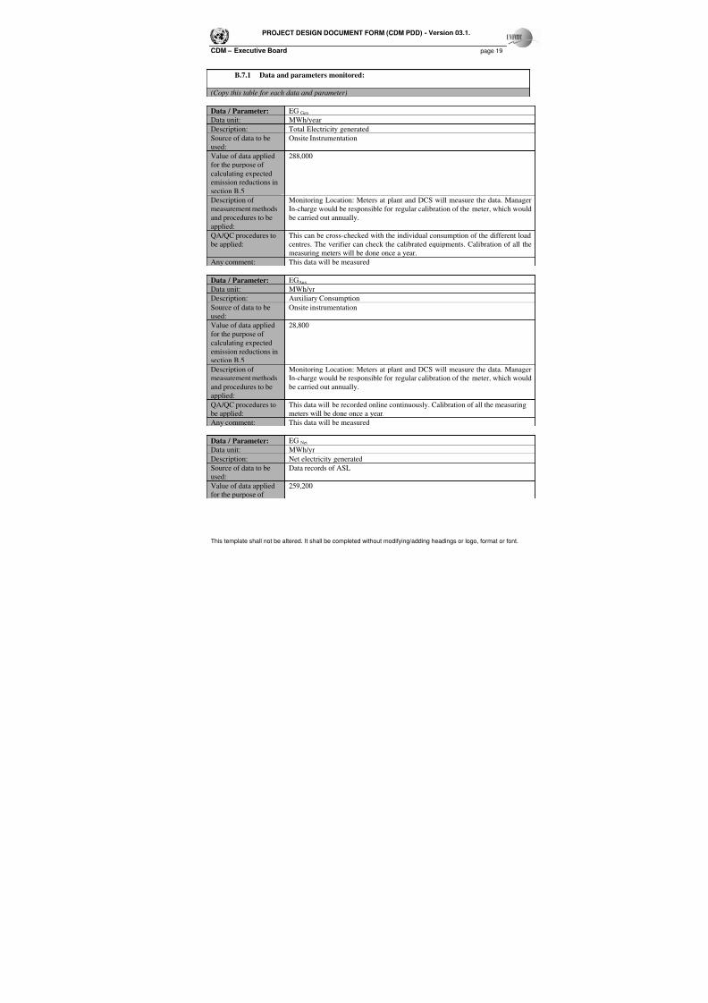
B.7.1 Data and parameters monitored:
(Copy this table for each data and parameter)
Data / Parameter: EG Gen Data unit: MWh/year
Description: Total Electricity generated
Source of data to be
used:
Onsite Instrumentation
Value of data applied
for the purpose of
calculating expected
emission reductions in
section B.5
288,000
Description of
measurement methods
and procedures to beapplied:
Monitoring Location: Meters at plant and DCS will measure the data. Manager
In-charge would be responsible for regular calibration of the meter, which would
be carried out annually.
QA/QC procedures to
be applied:
This can be cross-checked with the individual consumption of the different load
centres. The verifier can check the calibrated equipments. Calibration of all the
measuring meters will be done once a year.
Any comment: This data will be measured
Data / Parameter: EGAux
Data unit: MWh/yr
Description: Auxiliary Consumption
Source of data to be
used:
Onsite instrumentation
Value of data applied
for the purpose of
calculating expected
emission reductions in
section B.5
28,800
Description of
measurement methods
and procedures to be
applied:
Monitoring Location: Meters at plant and DCS will measure the data. Manager
In-charge would be responsible for regular calibration of the meter, which would
be carried out annually.
QA/QC procedures to
be applied:
This data will be recorded online continuously. Calibration of all the measuring
meters will be done once a year.
Any comment: This data will be measured
Data / Parameter: EG Net Data unit: MWh/yr
Description: Net electricity generated
Source of data to be
used:
Data records of ASL
Value of data applied
for the purpose of
259,200
7/18/2019 Aarti Steel WHR PDD
http://slidepdf.com/reader/full/aarti-steel-whr-pdd 20/34
PROJECT DESIGN DOCUMENT FORM (CDM PDD) - Version 03.1.
CDM – Executive Board page 20
This template shall not be altered. It shall be completed without modifying/adding headings or logo, format or font.
calculating expected
emission reductions in
section B.5
Description of
measurement methodsand procedures to be
applied:
-
QA/QC procedures to
be applied:
-
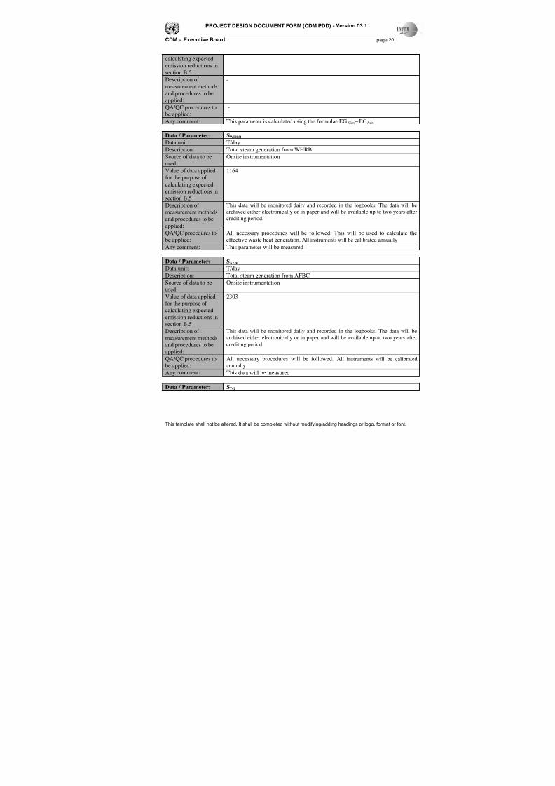
Any comment: This parameter is calculated using the formulae EG Gen – EGAux
Data / Parameter: SWHRB
Data unit: T/day
Description: Total steam generation from WHRB
Source of data to be
used:
Onsite instrumentation
Value of data appliedfor the purpose of
calculating expected
emission reductions in
section B.5
1164
Description of
measurement methods
and procedures to be
applied:
This data will be monitored daily and recorded in the logbooks. The data will be
archived either electronically or in paper and will be available up to two years after
crediting period.
QA/QC procedures to
be applied:
All necessary procedures will be followed. This will be used to calculate the
effective waste heat generation. All instruments will be calibrated annually
Any comment: This parameter will be measured
Data / Parameter: SAFBC
Data unit: T/day
Description: Total steam generation from AFBC
Source of data to be
used:
Onsite instrumentation
Value of data applied
for the purpose of
calculating expected
emission reductions in
section B.5
2303
Description of
measurement methods
and procedures to beapplied:
This data will be monitored daily and recorded in the logbooks. The data will be
archived either electronically or in paper and will be available up to two years after
crediting period.
QA/QC procedures to
be applied:
All necessary procedures will be followed. All instruments will be calibrated
annually.
Any comment: This data will be measured
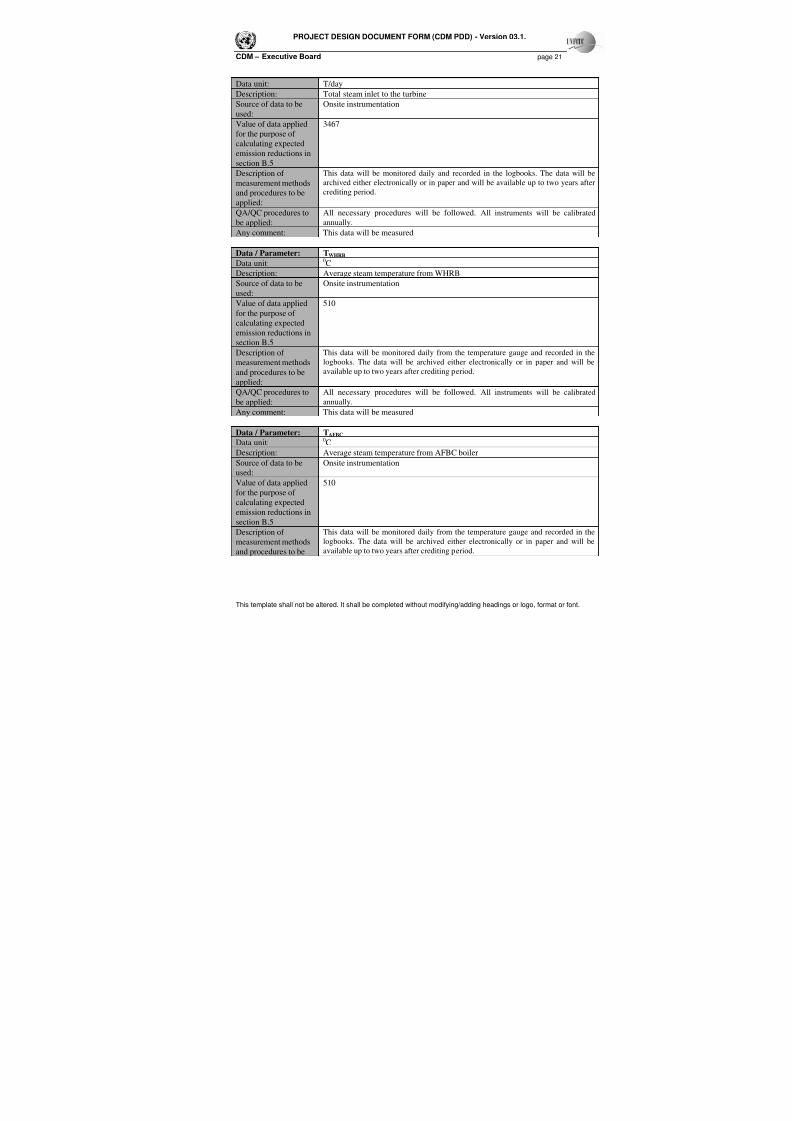
Data / Parameter: STG
7/18/2019 Aarti Steel WHR PDD
http://slidepdf.com/reader/full/aarti-steel-whr-pdd 21/34
PROJECT DESIGN DOCUMENT FORM (CDM PDD) - Version 03.1.
CDM – Executive Board page 21
This template shall not be altered. It shall be completed without modifying/adding headings or logo, format or font.
Data unit: T/day
Description: Total steam inlet to the turbine
Source of data to be
used:
Onsite instrumentation
Value of data appliedfor the purpose of
calculating expected
emission reductions in
section B.5
3467
Description of
measurement methods
and procedures to be
applied:
This data will be monitored daily and recorded in the logbooks. The data will be
archived either electronically or in paper and will be available up to two years after
crediting period.
QA/QC procedures to
be applied:
All necessary procedures will be followed. All instruments will be calibrated
annually.
Any comment: This data will be measured
Data / Parameter: TWHRB
Data unit:0C
Description: Average steam temperature from WHRB
Source of data to be
used:
Onsite instrumentation
Value of data applied
for the purpose of
calculating expected
emission reductions in
section B.5
510
Description of
measurement methods
and procedures to be
applied:
This data will be monitored daily from the temperature gauge and recorded in the
logbooks. The data will be archived either electronically or in paper and will be
available up to two years after crediting period.
QA/QC procedures to
be applied:
All necessary procedures will be followed. All instruments will be calibrated
annually.
Any comment: This data will be measured
Data / Parameter: TAFBC
Data unit:0C
Description: Average steam temperature from AFBC boiler
Source of data to be
used:
Onsite instrumentation
Value of data applied
for the purpose ofcalculating expected
emission reductions in
section B.5
510
Description of
measurement methods
and procedures to be
This data will be monitored daily from the temperature gauge and recorded in the
logbooks. The data will be archived either electronically or in paper and will be
available up to two years after crediting period.
7/18/2019 Aarti Steel WHR PDD
http://slidepdf.com/reader/full/aarti-steel-whr-pdd 22/34
PROJECT DESIGN DOCUMENT FORM (CDM PDD) - Version 03.1.
CDM – Executive Board page 22
This template shall not be altered. It shall be completed without modifying/adding headings or logo, format or font.
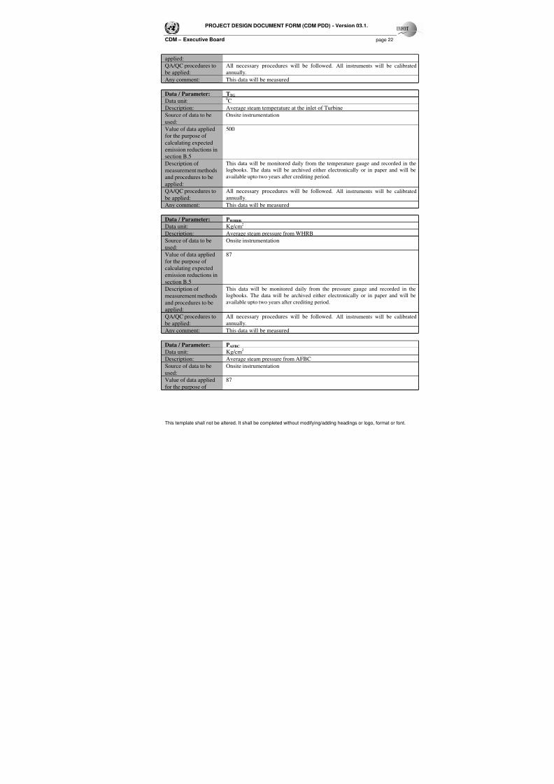
applied:
QA/QC procedures to
be applied:
All necessary procedures will be followed. All instruments will be calibrated
annually.
Any comment: This data will be measured
Data / Parameter: TTG
Data unit:0C
Description: Average steam temperature at the inlet of Turbine
Source of data to be
used:
Onsite instrumentation
Value of data applied
for the purpose of
calculating expected
emission reductions in
section B.5
500
Description of
measurement methodsand procedures to be
applied:
This data will be monitored daily from the temperature gauge and recorded in the
logbooks. The data will be archived either electronically or in paper and will beavailable upto two years after crediting period.
QA/QC procedures to
be applied:
All necessary procedures will be followed. All instruments will be calibrated
annually.
Any comment: This data will be measured
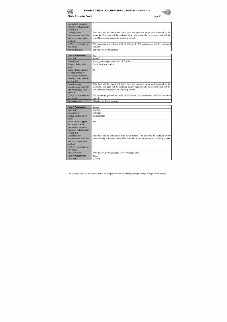
Data / Parameter: PWHRB
Data unit: Kg/cm2
Description: Average steam pressure from WHRB
Source of data to be
used:
Onsite instrumentation
Value of data appliedfor the purpose of
calculating expected
emission reductions in
section B.5
87
Description of
measurement methods
and procedures to be
applied:
This data will be monitored daily from the pressure gauge and recorded in the
logbooks. The data will be archived either electronically or in paper and will be
available upto two years after crediting period.
QA/QC procedures to
be applied:
All necessary procedures will be followed. All instruments will be calibrated
annually.
Any comment: This data will be measured
Data / Parameter: PAFBC
Data unit: Kg/cm2
Description: Average steam pressure from AFBC
Source of data to be
used:
Onsite instrumentation
Value of data applied
for the purpose of
87
7/18/2019 Aarti Steel WHR PDD
http://slidepdf.com/reader/full/aarti-steel-whr-pdd 23/34
PROJECT DESIGN DOCUMENT FORM (CDM PDD) - Version 03.1.
CDM – Executive Board page 23
This template shall not be altered. It shall be completed without modifying/adding headings or logo, format or font.
calculating expected
emission reductions in
section B.5
Description of
measurement methodsand procedures to be
applied:
This data will be monitored daily from the pressure gauge and recorded in the
logbooks. The data will be archived either electronically or in paper and will beavailable upto two years after crediting period.
QA/QC procedures to
be applied:
All necessary procedures will be followed. All instruments will be calibrated
annually.
Any comment: This data will be measured
Data / Parameter: PTG
Data unit: Kg/cm2
Description: Average steam pressure inlet of Turbine
Source of data to be
used:
Onsite instrumentation
Value of data appliedfor the purpose of
calculating expected
emission reductions in
section B.5
85
Description of
measurement methods
and procedures to be
applied:
This data will be monitored daily from the pressure gauge and recorded in the
logbooks. The data will be archived either electronically or in paper and will be
available upto two years after crediting period.
QA/QC procedures to
be applied:
All necessary procedures will be followed. All instruments will be calibrated
annually.
Any comment: This data will be measured
Data / Parameter: hWHRB
Data unit: kCal/kg
Description: Enthaply
Source of data to be
used:
Steam tables
Value of data applied
for the purpose of
calculating expected
emission reductions in
section B.5
815
Description of
measurement methods
and procedures to beapplied:
This data will be calculated from steam tables. The data will be archived either
electronically or in paper and will be available up to two years after crediting period.
QA/QC procedures to
be applied:
-
Any comment: This data will be calculated from the steam table
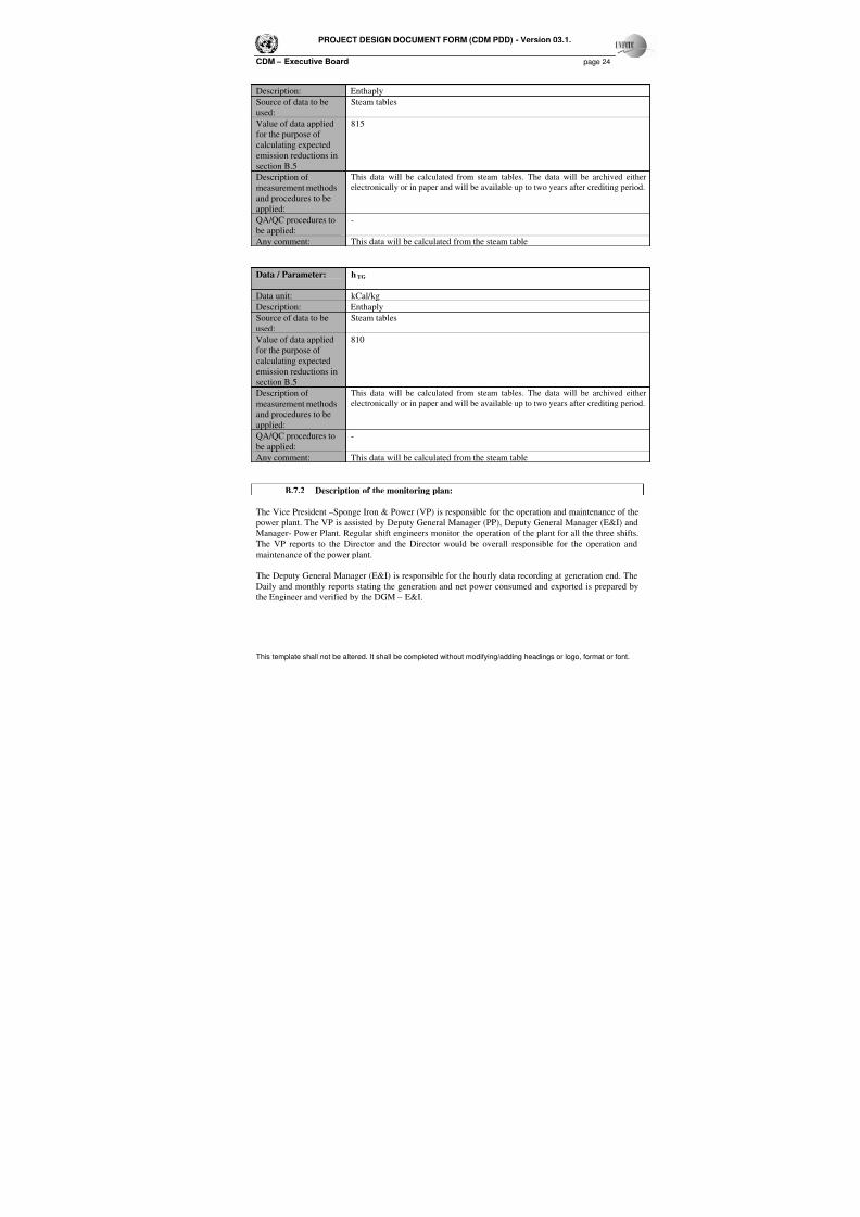
Data / Parameter: hAFBC
Data unit: kCal/kg
7/18/2019 Aarti Steel WHR PDD
http://slidepdf.com/reader/full/aarti-steel-whr-pdd 24/34
PROJECT DESIGN DOCUMENT FORM (CDM PDD) - Version 03.1.
CDM – Executive Board page 24
This template shall not be altered. It shall be completed without modifying/adding headings or logo, format or font.
Description: Enthaply
Source of data to be
used:
Steam tables
Value of data applied
for the purpose ofcalculating expected
emission reductions in
section B.5
815
Description of
measurement methods
and procedures to be
applied:
This data will be calculated from steam tables. The data will be archived either
electronically or in paper and will be available up to two years after crediting period.
QA/QC procedures to
be applied:
-
Any comment: This data will be calculated from the steam table
Data / Parameter: h TG
Data unit: kCal/kg
Description: Enthaply
Source of data to be
used:
Steam tables
Value of data applied
for the purpose of
calculating expected
emission reductions in
section B.5
810
Description of
measurement methods
and procedures to be
applied:
This data will be calculated from steam tables. The data will be archived either
electronically or in paper and will be available up to two years after crediting period.
QA/QC procedures to
be applied:
-
Any comment: This data will be calculated from the steam table
B.7.2 Description of the monitoring plan:
The Vice President –Sponge Iron & Power (VP) is responsible for the operation and maintenance of the
power plant. The VP is assisted by Deputy General Manager (PP), Deputy General Manager (E&I) and
Manager- Power Plant. Regular shift engineers monitor the operation of the plant for all the three shifts.The VP reports to the Director and the Director would be overall responsible for the operation and
maintenance of the power plant.
The Deputy General Manager (E&I) is responsible for the hourly data recording at generation end. The
Daily and monthly reports stating the generation and net power consumed and exported is prepared by
the Engineer and verified by the DGM – E&I.
7/18/2019 Aarti Steel WHR PDD
http://slidepdf.com/reader/full/aarti-steel-whr-pdd 25/34
PROJECT DESIGN DOCUMENT FORM (CDM PDD) - Version 03.1.
CDM – Executive Board page 25
This template shall not be altered. It shall be completed without modifying/adding headings or logo, format or font.
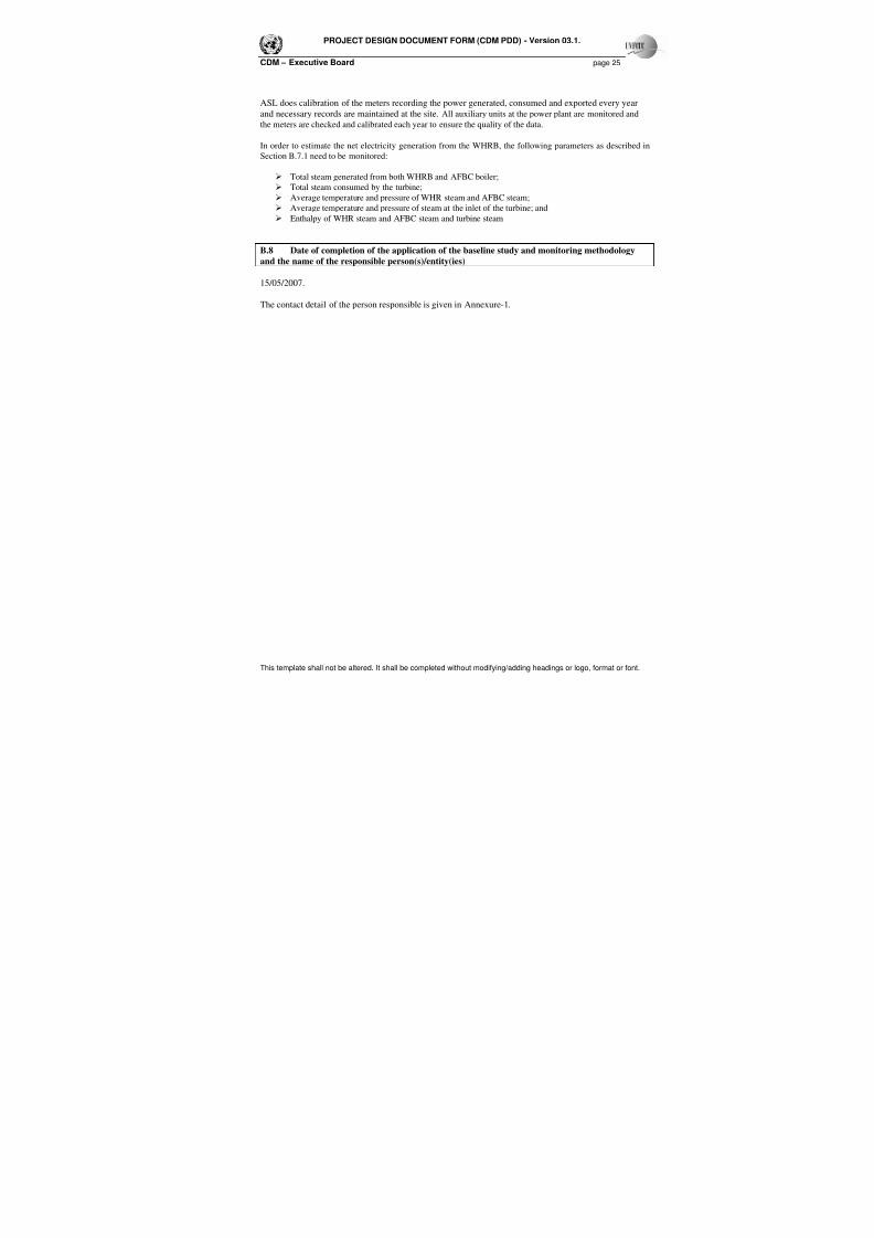
ASL does calibration of the meters recording the power generated, consumed and exported every year
and necessary records are maintained at the site. All auxiliary units at the power plant are monitored and
the meters are checked and calibrated each year to ensure the quality of the data.
In order to estimate the net electricity generation from the WHRB, the following parameters as described in
Section B.7.1 need to be monitored:
Total steam generated from both WHRB and AFBC boiler;
Total steam consumed by the turbine;
Average temperature and pressure of WHR steam and AFBC steam;
Average temperature and pressure of steam at the inlet of the turbine; and
Enthalpy of WHR steam and AFBC steam and turbine steam
B.8 Date of completion of the application of the baseline study and monitoring methodology
and the name of the responsible person(s)/entity(ies)
15/05/2007.
The contact detail of the person responsible is given in Annexure-1.
7/18/2019 Aarti Steel WHR PDD
http://slidepdf.com/reader/full/aarti-steel-whr-pdd 26/34
PROJECT DESIGN DOCUMENT FORM (CDM PDD) - Version 03.1.
CDM – Executive Board page 26
This template shall not be altered. It shall be completed without modifying/adding headings or logo, format or font.
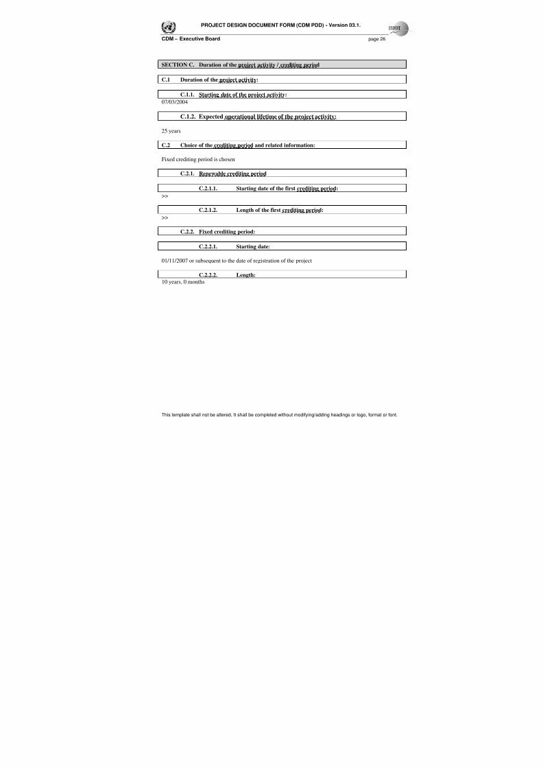
SECTION C. Duration of the project activity / crediting period
C.1 Duration of the project activity:
C.1.1. Starting date of the project activity:
07/03/2004
C.1.2. Expected operational lifetime of the project activity:
25 years
C.2 Choice of the crediting period and related information:
Fixed crediting period is chosen
C.2.1. Renewable crediting period
C.2.1.1. Starting date of the first crediting period:
>>
C.2.1.2. Length of the first crediting period:
>>
C.2.2. Fixed crediting period:
C.2.2.1. Starting date:
01/11/2007 or subsequent to the date of registration of the project
C.2.2.2. Length:
10 years, 0 months
7/18/2019 Aarti Steel WHR PDD
http://slidepdf.com/reader/full/aarti-steel-whr-pdd 27/34
PROJECT DESIGN DOCUMENT FORM (CDM PDD) - Version 03
CDM – Executive Board
This template shall not be altered. It shall be completed without modifying/adding headings or logo, format or font.
SECTION D. Environmental impacts
>>
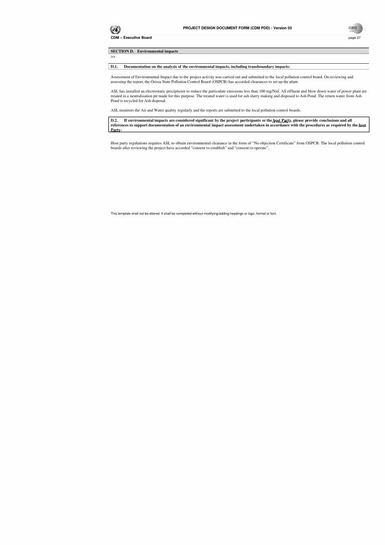
D.1. Documentation on the analysis of the environmental impacts, including transboundary impacts:
Assessment of Environmental Impact due to the project activity was carried out and submitted to the local pollution
assessing the report, the Orissa State Pollution Control Board (OSPCB) has accorded clearances to set up the plant
ASL has installed an electrostatic precipitator to reduce the particulate emissions less than 100 mg/Nm3. All effluen
treated in a neutralisation pit made for this purpose. The treated water is used for ash slurry making and disposed to
Pond is recycled for Ash disposal.
ASL monitors the Air and Water quality regularly and the reports are submitted to the local pollution control board
D.2. If environmental impacts are considered significant by the project participants or the host Party, ple
references to support documentation of an environmental impact assessment undertaken in accordance with
Party:
Host party regulations requires ASL to obtain environmental clearance in the form of “No objection Certificate” f
boards after reviewing the project have accorded “consent to establish” and “consent to operate”.
7/18/2019 Aarti Steel WHR PDD
http://slidepdf.com/reader/full/aarti-steel-whr-pdd 28/34
PROJECT DESIGN DOCUMENT FORM (CDM PDD) - Version 03
CDM – Executive Board
This template shall not be altered. It shall be completed without modifying/adding headings or logo, format or font.
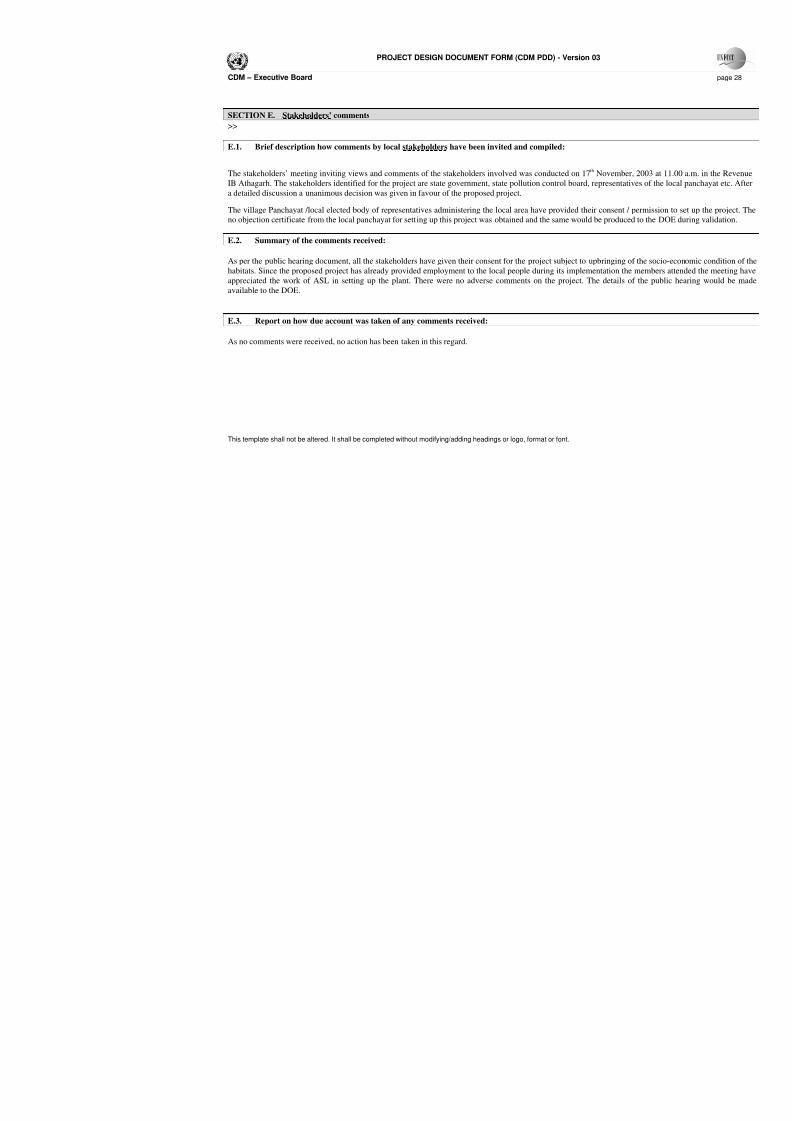
SECTION E. Stakeholders’ comments
>>
E.1. Brief description how comments by local stakeholders have been invited and compiled:
The stakeholders’ meeting inviting views and comments of the stakeholders involved was conducted on 17th Nov
IB Athagarh. The stakeholders identified for the project are state government, state pollution control board, repres
a detailed discussion a unanimous decision was given in favour of the proposed project.
The village Panchayat /local elected body of representatives administering the local area have provided their cons
no objection certificate from the local panchayat for setting up this project was obtained and the same would be pro
E.2. Summary of the comments received:
As per the public hearing document, all the stakeholders have given their consent for the project subject to upbring
habitats. Since the proposed project has already provided employment to the local people during its implementatio
appreciated the work of ASL in setting up the plant. There were no adverse comments on the project. The det
available to the DOE.
E.3. Report on how due account was taken of any comments received:
As no comments were received, no action has been taken in this regard.
7/18/2019 Aarti Steel WHR PDD
http://slidepdf.com/reader/full/aarti-steel-whr-pdd 29/34
This template shall not be altered. It shall be completed without modifying/adding headings or logo, format or font.
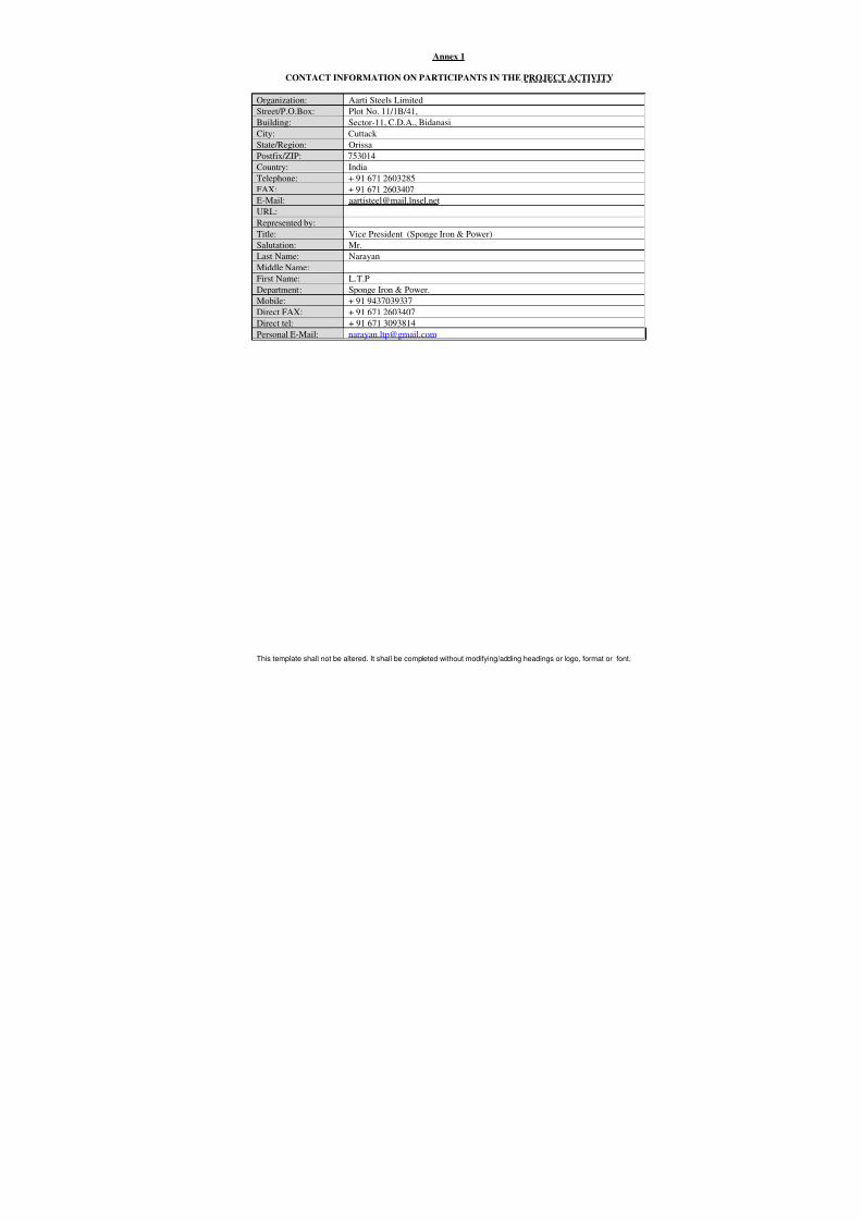
Annex 1
CONTACT INFORMATION ON PARTICIPANTS IN THE PROJECT ACTIVITY
Organization: Aarti Steels Limited
Street/P.O.Box: Plot No. 11/1B/41,
Building: Sector-11, C.D.A., Bidanasi
City: CuttackState/Region: Orissa
Postfix/ZIP: 753014
Country: India
Telephone: + 91 671 2603285
FAX: + 91 671 2603407
E-Mail: [email protected]
URL:
Represented by:
Title: Vice President (Sponge Iron & Power)
Salutation: Mr.
Last Name: Narayan
Middle Name:First Name: L.T.P
Department: Sponge Iron & Power.
Mobile: + 91 9437039337
Direct FAX: + 91 671 2603407
Direct tel: + 91 671 3093814
Personal E-Mail: [email protected]

7/18/2019 Aarti Steel WHR PDD
http://slidepdf.com/reader/full/aarti-steel-whr-pdd 30/34
This template shall not be altered. It shall be completed without modifying/adding headings or logo, format or font.
Annex 2
INFORMATION REGARDING PUBLIC FUNDING
No public funding for this project

7/18/2019 Aarti Steel WHR PDD
http://slidepdf.com/reader/full/aarti-steel-whr-pdd 31/34
This template shall not be altered. It shall be completed without modifying/adding headings or logo, format or font.
Annex 3
BASELINE INFORMATION
The project activity generates electricity by using waste gases emanating out of the DRI kiln in the
production facility. Thus it displaces equivalent quantum of power which otherwise would have been
generated in a captive coal and coal washery rejects fired plant. The emission reduction due to the project
activity will depend upon the net quantity of electricity supplied by the WHRB and the CO 2 baseline
emission factor of the coal and coal washery rejects based captive power plant.
Emission Reduction Estimation from the Project Activity
Calculation of baseline emission factor (t CO2 /MWh)
Carbon Emission Factor of the Coal
(including coal washery rejects)used
in the baseline plant (tC/TJ)
26.1
Efficiency of the baseline plant 28 %
Emission Factor of the baseline plant
(t CO2 /MWh)
1.22
Emission Reduction due to the project activity
Year Emission Reduction (t CO2)
Year 1 106,145.1
Year 2 106,145.1
Year 3 106,145.1
Year 4 106,145.1
Year 5 106,145.1
Year 6 106,145.1
Year 7 106,145.1
Year 8 106,145.1 Year 9 106,145.1
Year 10 106,145.1

7/18/2019 Aarti Steel WHR PDD
http://slidepdf.com/reader/full/aarti-steel-whr-pdd 32/34
This template shall not be altered. It shall be completed without modifying/adding headings or logo, format or font.
Annex 4
MONITORING PLAN
A. THE METHODOLOGY REQUIRES MONITORING OF THE FOLLOWINGS
1. Net electricity generation2. Auxiliary power consumption
3. Steam flow at the outlet of WHRB, AFBCB and inlet to TG
4. Steam Temperature at the outlet of WHRB, AFBCB and inlet to TG
5. Steam pressure at the outlet of WHRB, AFBCB and inlet to TG
ASL has installed meters to monitor all the above mentioned parameters. All the meters are annually
calibrated to ensure a proper monitoring mechanism.
B. ESTIMATION OF NET POWER GENERATED FROM WHRB
Contribution to Net Electricity Generation from WHRB = (% Contribution of Enthalpy of Steam fromWHRB X Net Electricity Generated )
Note :
% Contribution of Enthalpy of Steam from WHRB is ascertained from the total enthalpy of the steam at
the TG inlet and the steam enthalpy at the WHRB outlet according to the table given in section B.7.1 of
this document “data and parameters monitored”.
1. Steam enthalpy (hWHRB & hAFBC) in KCal/kg is derived by using thermodynamic steam tables, based
on the pressure and temperature readings.
2. Flow quantity (SWHRB & SAFBC ) is determined from the recorded steam flow at DCS.

7/18/2019 Aarti Steel WHR PDD
http://slidepdf.com/reader/full/aarti-steel-whr-pdd 33/34
This template shall not be altered. It shall be completed without modifying/adding headings or logo, format or font.
Annex 5
ABBREVIATIONS
AFBC Alternate Fluidised Bed Combustion
ASL Aarti Steels Limited
CDM Clean Development Mechanism
CPP Captive Power Plant
CER Certified Emission Reduction
CEA Central Electricity Authority
Cm Centimeter
DRI Direct Reduced Iron
DOE Designated Operational Entity
ESP Electrostatic Precipitator
GHG Green House Gas
GRIDCO Grid Corporation of Orissa Limited
INR Indian Rupees
IPPs Independent Power Producers
Kg Kilogram
KWh Kilowatt Hour
MW Mega Watt
MWh Megawatt hour
MOU Memoranding of Understaning
OSPCB Orrissa State Pollution Control Board
PLF Plant Load Factor
PPA Power Purchase Agreement
RPM Revolutions per minute
TG Turbine Generator
TPH Ton Per Hour
UNFCCC United Nations Framework Convention of Climate Change
WHRB Waste Heat Recovery Boiler
7/18/2019 Aarti Steel WHR PDD
http://slidepdf.com/reader/full/aarti-steel-whr-pdd 34/34
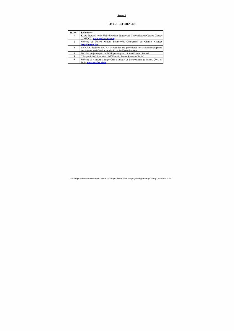
Annex 6
LIST OF REFERENCES
Sr. No References
1. Kyoto Protocol to the United Nations Framework Convention on Climate Change(UNFCCC) www.unfccc.int/cdm
2. Website of United Nations Framework Convention on Climate Change,
http://unfccc.int
3. UNFCCC decision 17/CP.7: Modalities and procedures for a clean development
mechanism as defined in article 12 of the Kyoto Protocol
4. Detailed project report on WHR power plant of Aarti Steels Limited
5. CEA published document “16th Electric Power Survey of India”
6. Website of Climate Change Cell, Ministry of Environment & Forest, Govt. of
India. www.envfor.nic.in