AA12 - Experience with Particle Breakdown in Gas ... Experience with particle breakdown in gas...
10
1 Experience with particle breakdown in gas suspension calciners Benny Erik Raahauge 1 and Niranjan Devarajan 2 1. General Manager, Alumina Technology, Minerals Division, FLSmidth A/S 2. Senior Manager Process, Alumina Technology, Minerals Division, FLSmidth Private Limited, India Corresponding Author: [email protected] Abstract Since calcination in Rotary Kilns was replaced with calcination in Stationary Calciners, following the energy crisis in the 1970'ties, Particle Strength, Size and Breakdown of the Alumina produced has been of major concern in design and operation of the Hydrate Precipitation circuit followed by calcination in Stationary Calciners. This paper outlines the FLSmidth experience with particle breakdown in Gas Suspension Calciners (GSC) over the past 35 years from different hydrate sources in both pilot and full scale Gas Suspension Calciners of various design and capacity. The particle breakdown reported in the GSC units ranges from 100 % upwards of the particle breakdown observed in rotary kilns dependent on Hydrate Quality and GSC design / operation. Some impact on smelter performance reported in the literature will be covered as well. Keywords: Precipitation; Calcination; Alumina; Particle Size. 1. Introduction Over the past 40+ years significant technology changes/shifts has taken place in Refineries and Aluminium Smelters, the only customer for SGA. The drivers for these changes were and still are economy of scale, energy efficiency and/or improved environmental performance. In 1935 the first Rotary Kiln for calcination of Aluminium Hydroxide with a capacity of 110 tpd alumina was installed. Until about 1972 where the largest Ø 4.3 x 122 m Rotary Kiln was contracted with a capacity of 1400 tpd sandy alumina, this technology dominated the industry (Figure 1, left). Figure 1. 3xØ 3.95 x 10⁷ m rotary kilns 3 x 4500TPD GSC units with bag filters. In 1952, Alcoa commissioned their first 300 tpd Fluid-Bed Calciner producing sandy alumina [1] and since the oil crisis in 1972 only Stationary Calciners have been installed in new Alumina Refineries for production of Smelter Grade Alumina (SGA) owing to about 25-30 % less fuel consumption per ton alumina produced in Stationary Calciners compared to Rotary Kilns.
Transcript of AA12 - Experience with Particle Breakdown in Gas ... Experience with particle breakdown in gas...
1
Experience with particle breakdown in gas suspension calciners
Benny Erik Raahauge1 and Niranjan Devarajan2 1. General Manager, Alumina Technology, Minerals Division, FLSmidth A/S
2. Senior Manager Process, Alumina Technology, Minerals Division, FLSmidth Private Limited, India Corresponding Author: [email protected]
Abstract
Since calcination in Rotary Kilns was replaced with calcination in Stationary Calciners, following the energy crisis in the 1970'ties, Particle Strength, Size and Breakdown of the Alumina produced has been of major concern in design and operation of the Hydrate Precipitation circuit followed by calcination in Stationary Calciners. This paper outlines the FLSmidth experience with particle breakdown in Gas Suspension Calciners (GSC) over the past 35 years from different hydrate sources in both pilot and full scale Gas Suspension Calciners of various design and capacity. The particle breakdown reported in the GSC units ranges from 100 % upwards of the particle breakdown observed in rotary kilns dependent on Hydrate Quality and GSC design / operation. Some impact on smelter performance reported in the literature will be covered as well.
Keywords: Precipitation; Calcination; Alumina; Particle Size.
1. Introduction
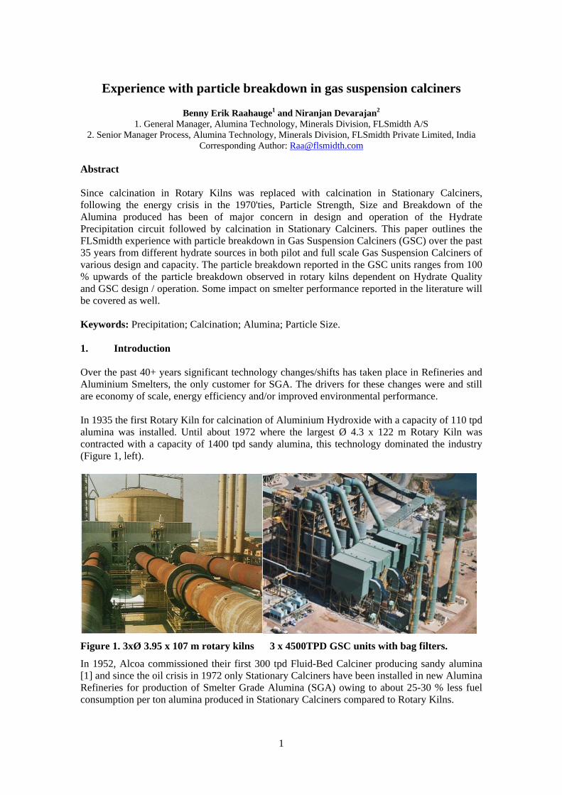
Over the past 40+ years significant technology changes/shifts has taken place in Refineries and Aluminium Smelters, the only customer for SGA. The drivers for these changes were and still are economy of scale, energy efficiency and/or improved environmental performance. In 1935 the first Rotary Kiln for calcination of Aluminium Hydroxide with a capacity of 110 tpd alumina was installed. Until about 1972 where the largest Ø 4.3 x 122 m Rotary Kiln was contracted with a capacity of 1400 tpd sandy alumina, this technology dominated the industry (Figure 1, left).
Figure 1. 3xØ 3.95 x 10⁷ m rotary kilns 3 x 4500TPD GSC units with bag filters.
In 1952, Alcoa commissioned their first 300 tpd Fluid-Bed Calciner producing sandy alumina [1] and since the oil crisis in 1972 only Stationary Calciners have been installed in new Alumina Refineries for production of Smelter Grade Alumina (SGA) owing to about 25-30 % less fuel consumption per ton alumina produced in Stationary Calciners compared to Rotary Kilns.
2
Today, almost all rotary kilns have been replaced with Stationary Calciners and many of the latest Gas Suspension Calciner (GSC) units [2, 3] are now equipped with Bag House/Fabric Filters (Figure 1, right) instead of Electrostatic Precipitators (ESP). The major reason being, that ESP units are not absolute filters because a plume of alumina dust is emitted from the ESP in case of a power failure.
2. Particle breakdown, alumina particle strength and hydrate precipitation Ever since the introduction of Stationary Calciners into alumina refineries, Particle Strength, Size and Breakdown of the Alumina produced has been of major concern in design and operation of the Hydrate Precipitation circuit supplying the Stationary Calciners with production hydrate.
2.1. Definitions of particle breakdown
Particle Breakdown (PB) measures the change in Particle Size Distribution on 45 Micron or 325 Mesh sieve size (Rotap) between Hydrate fed into the calcination plant and Alumina discharged from the calcination plant:
PB (%) = (wt% Hydrate > 45 µm) - (wt% Alumina > 45 µm) (1) Or:
PB (%) = (wt% Alumina < 45 µm) - (wt% Hydrate < 45 µm) (2)
In general, maximum 10 wt % < 45 Micron/325 Mesh in shipped SGA is specified by Smelters. But up to 15-20 % may be accepted at the Pot. The reason being that super fines measured as % SGA < 20 Microns (i.e. by Laser) is just as, if not more important, subject to the impact of super fines on the overall PSD and flowability of the alumina. Lindsay has reported [4], that resulting flowability (flow time) of the alumina has a negative impact on current efficiency and Green House gas generation in the Smelters. 2.2. Definition of alumina particle strength (Attrition Index) There is no generally accepted measurement method of Alumina Particle Strength or "toughness" [4], but the alumina industry has used the Alumina Attrition Index determined by the Forsyth-Hertwig test [5] modified and introduced by Alcoa many years back. The Alumina Attrition Index (AAI) is calculated as follows: AAI (%) = 100 [1 - (% Alumina > 45 µm)AFTER / (% Alumina > 45 µm)BEFORE ] (3) There is no general requirement by Smelters with respect to the Alumina Attrition Index in SGA. However, Smelters prefer strong or "tough" alumina particles that can withstand handling and passage through their Gas Treatment Centre or Dry Scrubbers prior to feeding the Pots [6]. This is to avoid excessive generation of fines and super fines with the negative impact on pot operation as mentioned above [4]. 2.3. Particle breakdown in rotary kilns and alumina Attrition Index of SGA For comparison and confidentially reasons, % Relative Particle Breakdown will be reported onwards in this paper. It is calculated as a % of the absolute wt% Particle Breakdown on 45 µm sieve (Rotap) observed in the Rotary Kiln or GS C at Eurallumina in Italy [8]. As seen from Table 1, there seems to be a relationship between Particle Breakdown in Rotary Kilns, Alumina Attrition Index and Hydrate Precipitation technology [7, 8, 9].
3
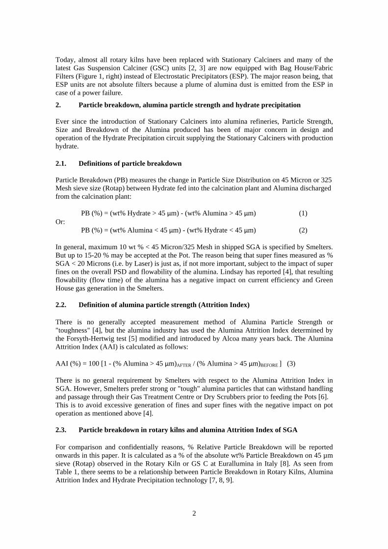
Table 1. Relative particle breakdown (PB) versus alumina attrition index (AAI).
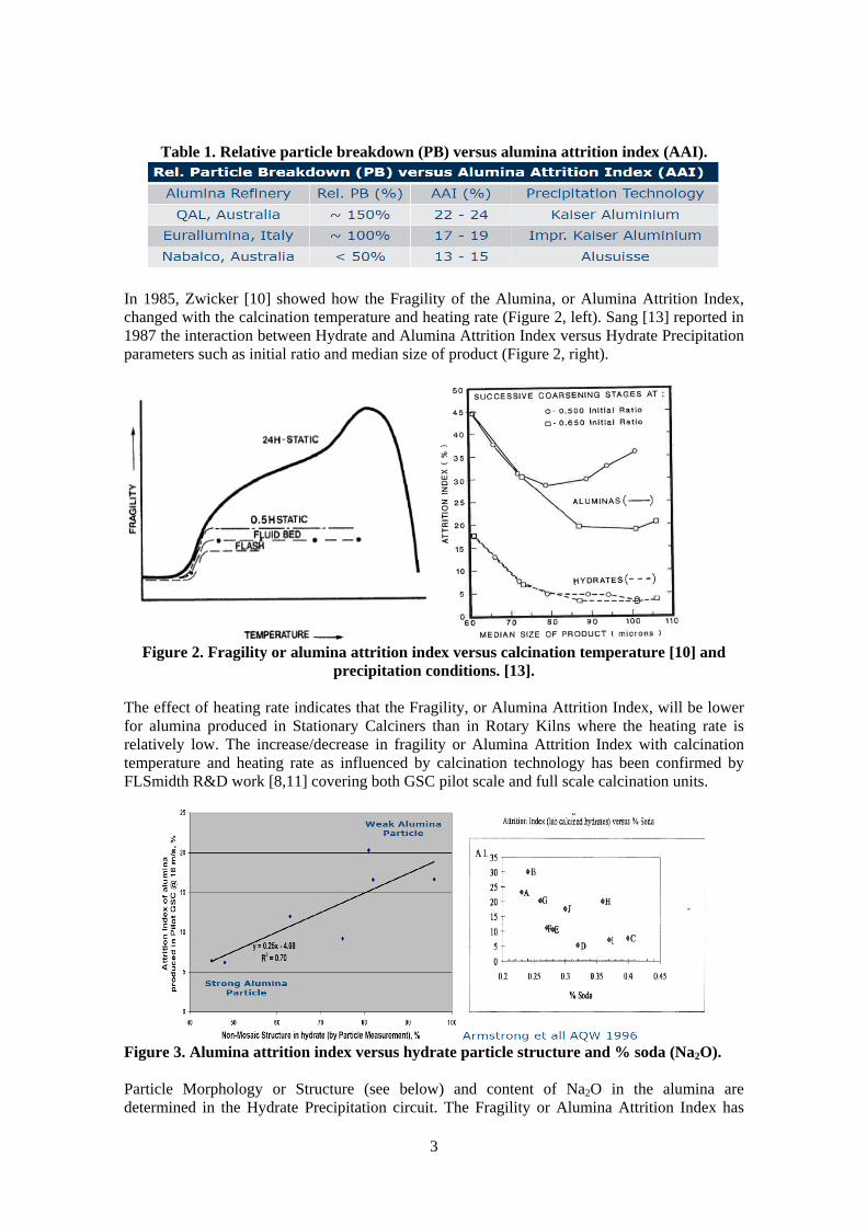
In 1985, Zwicker [10] showed how the Fragility of the Alumina, or Alumina Attrition Index, changed with the calcination temperature and heating rate (Figure 2, left). Sang [13] reported in 1987 the interaction between Hydrate and Alumina Attrition Index versus Hydrate Precipitation parameters such as initial ratio and median size of product (Figure 2, right).
Figure 2. Fragility or alumina attrition index versus calcination temperature [10] and
precipitation conditions. [13]. The effect of heating rate indicates that the Fragility, or Alumina Attrition Index, will be lower for alumina produced in Stationary Calciners than in Rotary Kilns where the heating rate is relatively low. The increase/decrease in fragility or Alumina Attrition Index with calcination temperature and heating rate as influenced by calcination technology has been confirmed by FLSmidth R&D work [8,11] covering both GSC pilot scale and full scale calcination units.
Figure 3. Alumina attrition index versus hydrate particle structure and % soda (Na2O). Particle Morphology or Structure (see below) and content of Na2O in the alumina are determined in the Hydrate Precipitation circuit. The Fragility or Alumina Attrition Index has
4
been shown (Figure 3, left) to increase with increasing content of non-mosaic particle structure [11], and (Figure 3, right) decreasing content of Na2O in the alumina [12].
2.4. Developments in hydrate precipitation technology
Around 1970 Smelters were required to lower their emission of HF by installing Dry Scrubbers requiring Sandy alumina with SSA of 50–80 m2 /g. The change in smelter grade alumina quality to Sandy made Floury alumina [3] unacceptable to most Smelters overnight and it became a significant challenge for the Bayer Process designer/operators to change their precipitation circuit to produce a coarser Sandy alumina particle, while maintaining the high precipitation yield of producing Floury alumina [16, 17].
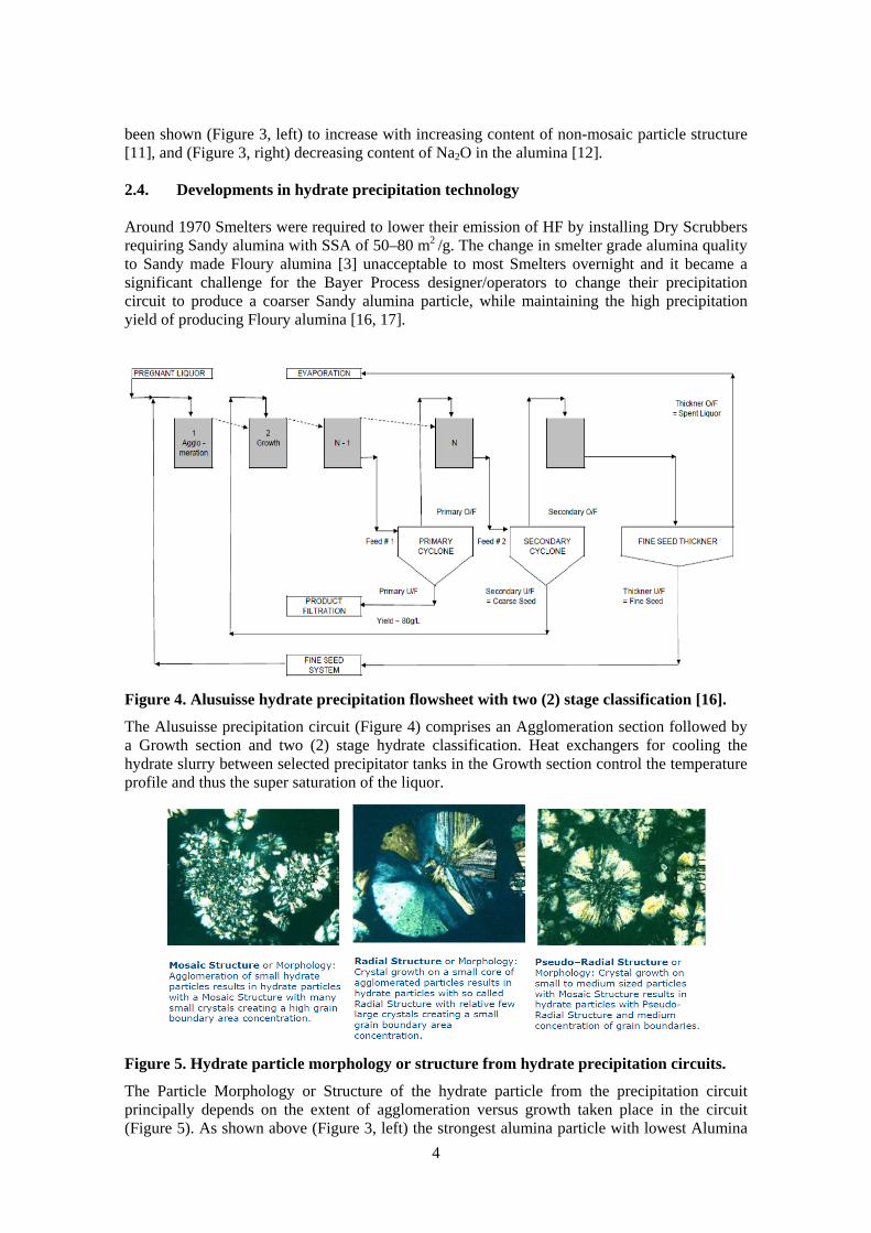
Figure 4. Alusuisse hydrate precipitation flowsheet with two (2) stage classification [16].
The Alusuisse precipitation circuit (Figure 4) comprises an Agglomeration section followed by a Growth section and two (2) stage hydrate classification. Heat exchangers for cooling the hydrate slurry between selected precipitator tanks in the Growth section control the temperature profile and thus the super saturation of the liquor.
Figure 5. Hydrate particle morphology or structure from hydrate precipitation circuits.
The Particle Morphology or Structure of the hydrate particle from the precipitation circuit principally depends on the extent of agglomeration versus growth taken place in the circuit (Figure 5). As shown above (Figure 3, left) the strongest alumina particle with lowest Alumina
5
Attrition Index after calcination is obtained from hydrate particles with relatively low content of non-mosaic structure.
A summary of design/operating data for Agglomeration and Growth sections is given by Anjier and Roberson [18]. The initial pregnant liquor super saturation (initial ratio) together with proper fine seed charge management are the major factors required for conditioning the agglomeration process so that a strong cemented hydrate particle is achieved from the Growth section resulting in alumina with low attrition index [13,14].
Hydrate from the precipitation is classified into coarse product for calcination, coarse seed subject to growth, and fine seed subject to agglomeration, by a two-stage (Figure 4) or one-stage (Figure 6) classification flowsheet.
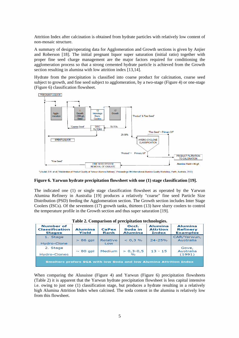
Figure 6. Yarwun hydrate precipitation flowsheet with one (1) stage classification [19]. The indicated one (1) or single stage classification flowsheet as operated by the Yarwun Alumina Refinery in Australia [19] produces a relatively "coarse" fine seed Particle Size Distribution (PSD) feeding the Agglomeration section. The Growth section includes Inter Stage Coolers (ISCs). Of the seventeen (17) growth tanks, thirteen (13) have slurry coolers to control the temperature profile in the Growth section and thus super saturation [19].
Table 2. Comparison of precipitation technologies.
When comparing the Alusuisse (Figure 4) and Yarwun (Figure 6) precipitation flowsheets (Table 2) it is apparent that the Yarwun hydrate precipitation flowsheet is less capital intensive i.e. owing to just one (1) classification stage, but produces a hydrate resulting in a relatively high Alumina Attrition Index when calcined. The soda content in the alumina is relatively low from this flowsheet.
6
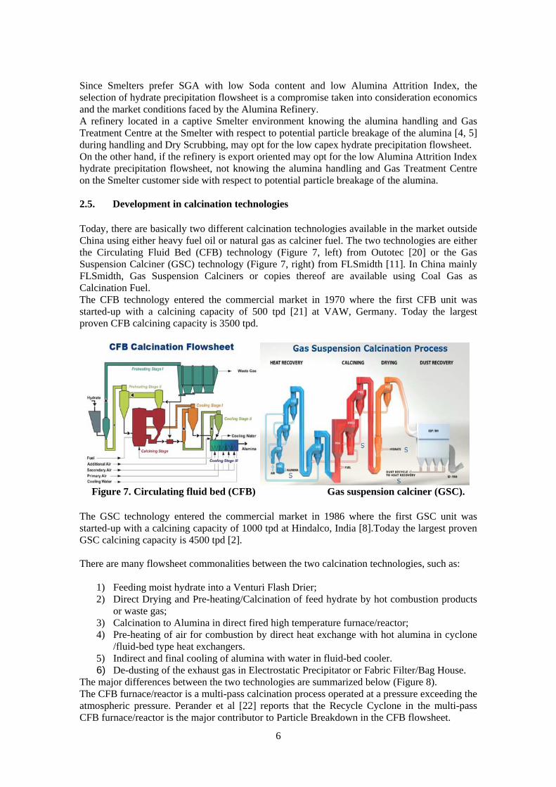
Since Smelters prefer SGA with low Soda content and low Alumina Attrition Index, the selection of hydrate precipitation flowsheet is a compromise taken into consideration economics and the market conditions faced by the Alumina Refinery. A refinery located in a captive Smelter environment knowing the alumina handling and Gas Treatment Centre at the Smelter with respect to potential particle breakage of the alumina [4, 5] during handling and Dry Scrubbing, may opt for the low capex hydrate precipitation flowsheet. On the other hand, if the refinery is export oriented may opt for the low Alumina Attrition Index hydrate precipitation flowsheet, not knowing the alumina handling and Gas Treatment Centre on the Smelter customer side with respect to potential particle breakage of the alumina. 2.5. Development in calcination technologies Today, there are basically two different calcination technologies available in the market outside China using either heavy fuel oil or natural gas as calciner fuel. The two technologies are either the Circulating Fluid Bed (CFB) technology (Figure 7, left) from Outotec [20] or the Gas Suspension Calciner (GSC) technology (Figure 7, right) from FLSmidth [11]. In China mainly FLSmidth, Gas Suspension Calciners or copies thereof are available using Coal Gas as Calcination Fuel. The CFB technology entered the commercial market in 1970 where the first CFB unit was started-up with a calcining capacity of 500 tpd [21] at VAW, Germany. Today the largest proven CFB calcining capacity is 3500 tpd.
Figure 7. Circulating fluid bed (CFB) Gas suspension calciner (GSC).
The GSC technology entered the commercial market in 1986 where the first GSC unit was started-up with a calcining capacity of 1000 tpd at Hindalco, India [8].Today the largest proven GSC calcining capacity is 4500 tpd [2]. There are many flowsheet commonalities between the two calcination technologies, such as:
1) Feeding moist hydrate into a Venturi Flash Drier; 2) Direct Drying and Pre-heating/Calcination of feed hydrate by hot combustion products
or waste gas; 3) Calcination to Alumina in direct fired high temperature furnace/reactor; 4) Pre-heating of air for combustion by direct heat exchange with hot alumina in cyclone
/fluid-bed type heat exchangers. 5) Indirect and final cooling of alumina with water in fluid-bed cooler. 6) De-dusting of the exhaust gas in Electrostatic Precipitator or Fabric Filter/Bag House.
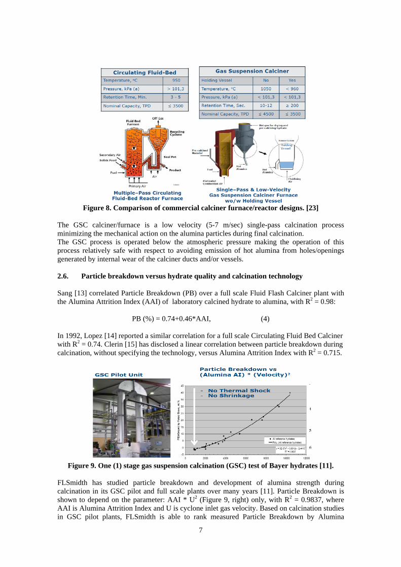
The major differences between the two technologies are summarized below (Figure 8). The CFB furnace/reactor is a multi-pass calcination process operated at a pressure exceeding the atmospheric pressure. Perander et al [22] reports that the Recycle Cyclone in the multi-pass CFB furnace/reactor is the major contributor to Particle Breakdown in the CFB flowsheet.
7
Figure 8. Comparison of commercial calciner furnace/reactor designs. [23]
The GSC calciner/furnace is a low velocity (5-7 m/sec) single-pass calcination process minimizing the mechanical action on the alumina particles during final calcination. The GSC process is operated below the atmospheric pressure making the operation of this process relatively safe with respect to avoiding emission of hot alumina from holes/openings generated by internal wear of the calciner ducts and/or vessels. 2.6. Particle breakdown versus hydrate quality and calcination technology Sang [13] correlated Particle Breakdown (PB) over a full scale Fluid Flash Calciner plant with the Alumina Attrition Index (AAI) of laboratory calcined hydrate to alumina, with R2 = 0.98:
PB (%) = 0.74+0.46*AAI, (4) In 1992, Lopez [14] reported a similar correlation for a full scale Circulating Fluid Bed Calciner with R2 = 0.74. Clerin [15] has disclosed a linear correlation between particle breakdown during calcination, without specifying the technology, versus Alumina Attrition Index with R2 = 0.715.
Figure 9. One (1) stage gas suspension calcination (GSC) test of Bayer hydrates [11].
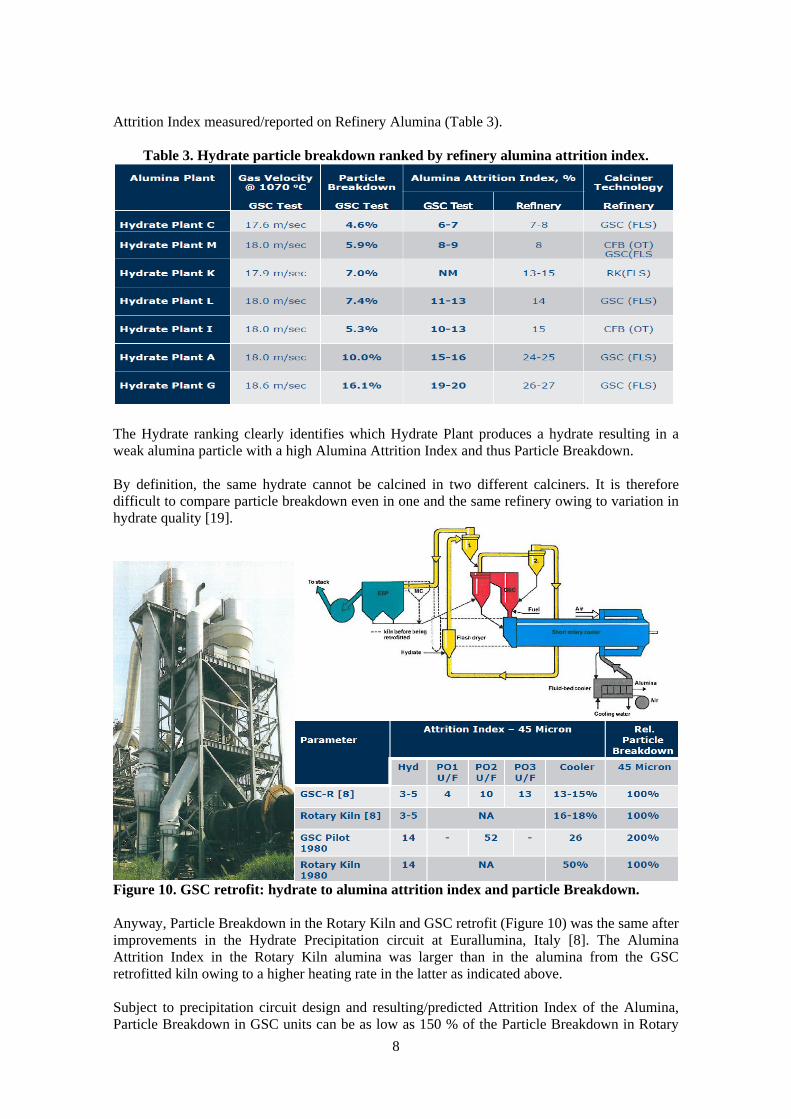
FLSmidth has studied particle breakdown and development of alumina strength during calcination in its GSC pilot and full scale plants over many years [11]. Particle Breakdown is shown to depend on the parameter: AAI * U2 (Figure 9, right) only, with R2 = 0.9837, where AAI is Alumina Attrition Index and U is cyclone inlet gas velocity. Based on calcination studies in GSC pilot plants, FLSmidth is able to rank measured Particle Breakdown by Alumina
8
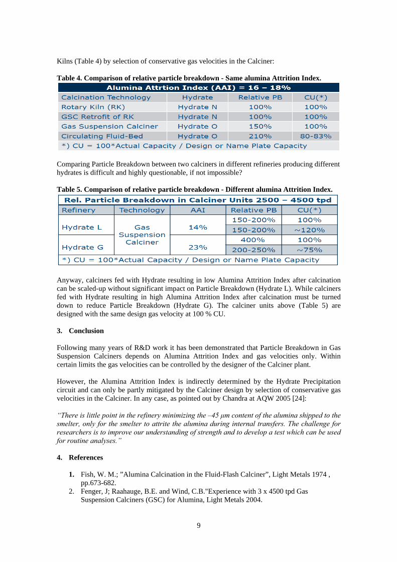
Attrition Index measured/reported on Refinery Alumina (Table 3).
Table 3. Hydrate particle breakdown ranked by refinery alumina attrition index.
The Hydrate ranking clearly identifies which Hydrate Plant produces a hydrate resulting in a weak alumina particle with a high Alumina Attrition Index and thus Particle Breakdown. By definition, the same hydrate cannot be calcined in two different calciners. It is therefore difficult to compare particle breakdown even in one and the same refinery owing to variation in hydrate quality [19].
Figure 10. GSC retrofit: hydrate to alumina attrition index and particle Breakdown. Anyway, Particle Breakdown in the Rotary Kiln and GSC retrofit (Figure 10) was the same after improvements in the Hydrate Precipitation circuit at Eurallumina, Italy [8]. The Alumina Attrition Index in the Rotary Kiln alumina was larger than in the alumina from the GSC retrofitted kiln owing to a higher heating rate in the latter as indicated above. Subject to precipitation circuit design and resulting/predicted Attrition Index of the Alumina, Particle Breakdown in GSC units can be as low as 150 % of the Particle Breakdown in Rotary
9
Kilns (Table 4) by selection of conservative gas velocities in the Calciner: Table 4. Comparison of relative particle breakdown - Same alumina Attrition Index.
Comparing Particle Breakdown between two calciners in different refineries producing different hydrates is difficult and highly questionable, if not impossible? Table 5. Comparison of relative particle breakdown - Different alumina Attrition Index.
Anyway, calciners fed with Hydrate resulting in low Alumina Attrition Index after calcination can be scaled-up without significant impact on Particle Breakdown (Hydrate L). While calciners fed with Hydrate resulting in high Alumina Attrition Index after calcination must be turned down to reduce Particle Breakdown (Hydrate G). The calciner units above (Table 5) are designed with the same design gas velocity at 100 % CU. 3. Conclusion Following many years of R&D work it has been demonstrated that Particle Breakdown in Gas Suspension Calciners depends on Alumina Attrition Index and gas velocities only. Within certain limits the gas velocities can be controlled by the designer of the Calciner plant. However, the Alumina Attrition Index is indirectly determined by the Hydrate Precipitation circuit and can only be partly mitigated by the Calciner design by selection of conservative gas velocities in the Calciner. In any case, as pointed out by Chandra at AQW 2005 [24]: “There is little point in the refinery minimizing the –45 μm content of the alumina shipped to the smelter, only for the smelter to attrite the alumina during internal transfers. The challenge for researchers is to improve our understanding of strength and to develop a test which can be used for routine analyses.” 4. References
1. Fish, W. M.; ”Alumina Calcination in the Fluid-Flash Calciner”, Light Metals 1974 ,
pp.673-682. 2. Fenger, J; Raahauge, B.E. and Wind, C.B."Experience with 3 x 4500 tpd Gas
Suspension Calciners (GSC) for Alumina, Light Metals 2004.
10
3. Raahauge, B.E., "Smelter Grade Alumina Quality in 40+ Year Perspective - Where to From Here?" Proceedings of the 10th International Alumina Quality Workshop, 2015.
4. Lindsay, S.J., "Key Physical Properties of Smelter Grade Alumina", Light Metals 2014, pp 597-601.
5. Forsyth,W.L. and Hertwig,W.R. "Attrition Characteristics of Fluid Cracking Cayalyst", Ind. Eng. Chem. June 1949, pp. 1200-1206.
6. Lindsay, S.J."Attrition of Alumina in Smelter Handling and Scubbing Systems", Light Metals 2011, pp. 163-168.
7. McIntosh, P. "Alumina Calcination Review", Alumina Technology Workshop, University of Sydney, NSW, 1985,pp.205-219.
8. Raahauge, B. E. et al.,”Experience with Gas Suspension Calciner for Alumina”, Light Metals 1991.
9. Bhasin, A.B. and Schenk, H.J."Productivity and Efficiency Improvements at the Gove Alumina Plant", Light Metals 1992, pp. 203-207.
10. Zwicker, J.D. “The Generation of Fines due to Heating of Aluminium Trihydrate“, Light Metals 1985, pp 373-395.
11. Wind, S., Jensen-Holm,C. And Raahauge, B.E. "Development of Particle Breakdown and Alumna strength During Calcination" Proceedings of the 9th International Alumina Quality Workshop, 2012.
12. Armstrong, L. et al., ”Alumina Attrition - Investigation of Hydrate Structure”, Proceedings of the 4th International Alumina Quality Workshop pp.239-249, 1996.
13. Sang, J.V.”Factors Affecting the Attrition Strength of Alumina Products”, Light Metals 1987, pp 121-127.
14. Lopez, J.E. and Quintero, I. "Evaluation of Agglomeration Stage Conditions to Control Alumina and Hydrate Particle Breakage", Light Metals 1992, pp.199-202.
15. P.Clerin, P. and Laurent, V.”Alumina Particle Breakage in Attrition Test”, Light Metals 2001, pp 41-47.
16. Howard, S.G. "Operation of the Alusuisse Precipitation Process at Gove, N.T. Australia", Light metals 1988, pp.125-128.
17. Tschamper O., "Improvements by the New Alusuisse Process for Producing Coarse Aluminium Hydrate in the Bayer Process", Light Metals 1981, pp.103-115.
18. Anjier, J.L. and Roberson, M.L."Precipitation Technology", Light Metals 1985, pp. 367-375.
19. Audet, D.R. et al., "Stabilization of Product Quality at Yarwun Alumina Refinery", 9th
International Alumina Quality Workshop pp.304-307, 2012. 20. Klett,C. et al.,"Improvement of Product Quality in Circulating Fluidized Bed
Calcination", Light Metals 2010, pp.33-38. 21. Williams, F. and Schmidt, HW.,"Flash- and CFB Calciners, History and Difficulties of
Development of Two Calcination Technologies", Light Metals 2012. 22. Perander, L. et all.,"Coal Gasification and Impacts on Alumina CFB Design",
Proceedings of the 10th International Alumina Quality Workshop pp.243-250, 2015. 23. L.M.Perander, J.B.Metson and C. Klett,”Two Perspectives on the Evolution and Future
of Alumina”,TMS Light Metals, pp151-155,(2011). 24. Chandraskar, S. et al.,”Alumina Fines’ Journey from Cradle to Grave”. Proceedings of
the 7th International Alumina Quality Workshop, Perth, Australia (2005).