A UML-based method for risk analysis of human-robot ...
11
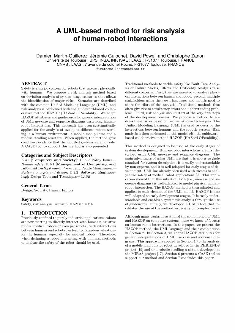
HAL Id: hal-01285195 https://hal.archives-ouvertes.fr/hal-01285195 Submitted on 9 Mar 2016 HAL is a multi-disciplinary open access archive for the deposit and dissemination of sci- entific research documents, whether they are pub- lished or not. The documents may come from teaching and research institutions in France or abroad, or from public or private research centers. L’archive ouverte pluridisciplinaire HAL, est destinée au dépôt et à la diffusion de documents scientifiques de niveau recherche, publiés ou non, émanant des établissements d’enseignement et de recherche français ou étrangers, des laboratoires publics ou privés. A UML-based method for risk analysis of human-robot interactions Damien Martin-Guillerez, Jérémie Guiochet, David Powell, Christophe Zanon To cite this version: Damien Martin-Guillerez, Jérémie Guiochet, David Powell, Christophe Zanon. A UML-based method for risk analysis of human-robot interactions. 2nd International Workshop on Software Engineering for Resilient Systems (SERENE), Apr 2010, London, United Kingdom. pp. 32-41, 10.1145/2401736.2401740. hal-01285195
Transcript of A UML-based method for risk analysis of human-robot ...

HAL Id: hal-01285195https://hal.archives-ouvertes.fr/hal-01285195
Submitted on 9 Mar 2016
HAL is a multi-disciplinary open accessarchive for the deposit and dissemination of sci-entific research documents, whether they are pub-lished or not. The documents may come fromteaching and research institutions in France orabroad, or from public or private research centers.
L’archive ouverte pluridisciplinaire HAL, estdestinée au dépôt et à la diffusion de documentsscientifiques de niveau recherche, publiés ou non,émanant des établissements d’enseignement et derecherche français ou étrangers, des laboratoirespublics ou privés.
A UML-based method for risk analysis of human-robotinteractions
Damien Martin-Guillerez, Jérémie Guiochet, David Powell, Christophe Zanon
To cite this version:Damien Martin-Guillerez, Jérémie Guiochet, David Powell, Christophe Zanon. A UML-basedmethod for risk analysis of human-robot interactions. 2nd International Workshop on SoftwareEngineering for Resilient Systems (SERENE), Apr 2010, London, United Kingdom. pp. 32-41,�10.1145/2401736.2401740�. �hal-01285195�
A UML-based method for risk analysisof human-robot interactions
Damien Martin-Guillerez, Jérémie Guiochet, David Powell and Christophe ZanonUniversité de Toulouse ; UPS, INSA, INP, ISAE ; LAAS ; F-31077 Toulouse, FRANCE
CNRS ; LAAS ; 7 avenue du colonel Roche, F-31077 Toulouse, [email protected]
ABSTRACTSafety is a major concern for robots that interact physicallywith humans. We propose a risk analysis method basedon deviation analysis of system usage scenarios that allowsthe identification of major risks. Scenarios are describedwith the common Unified Modeling Language (UML), andrisk analysis is performed with the guideword-based collab-orative method HAZOP (HAZard OP-erability). We adaptHAZOP attributes and guidewords for generic interpretationof UML use-case and sequence diagrams describing human-robot interactions. This approach has been systematicallyapplied for the analysis of two quite different robots work-ing in a human environment: a mobile manipulator and arobotic strolling assistant. When applied, the method gaveconclusive evidence that the modeled systems were not safe.A CASE tool to support this method is also presented.
Categories and Subject DescriptorsK.4.1 [Computers and Society]: Public Policy Issues—Human safety ; K.6.1 [Management of Computing andInformation Systems]: Project and People Management—Systems analysis and design; D.2.2 [Software Engineer-ing]: Design Tools and Techniques—CASE
General TermsDesign, Security, Human Factors
KeywordsSafety, risk analysis, scenario, HAZOP, UML
1. INTRODUCTIONPreviously confined to purely industrial applications, robotsare now starting to directly interact with humans: assistiverobots, medical robots or even pet robots. Such interactionsbetween humans and robots can lead to hazardous situationsfor the humans, especially for medical robots. Therefore,when designing a robot interacting with humans, methodsto analyze the safety of the robot should be used.
Traditional methods to tackle safety like Fault Tree Analy-sis or Failure Modes, Effects and Criticality Analysis raisedifferent concerns. First, they are unsuited to analyze physi-cal interactions between human and robot. Second, multiplestakeholders using their own languages and models need toshare the effort of risk analysis. Traditional methods thusoften give rise to consistency errors and understanding prob-lems. Third, risk analysis should start at the very first stepsof the development process. We propose a method to ad-dress these issues based on two well-known techniques. TheUnified Modeling Language (UML) is used to describe theinteractions between humans and the robotic system. Riskanalysis is then performed on this model with the guideword-based collaborative method HAZOP (HAZard OPerability).
This method is designed to be used at the early stages ofsystem development. Human-robot interactions are first de-scribed using UML use-case and sequence diagrams. Themain advantages of using UML are that it is now a de factostandard for system description, it is easily understandableby non-experts, and it is well adapted for early stages of de-velopment. UML has already been used with success to anal-yse the safety of medical robot applications [9]. This appli-cation showed that this subset of UML (i.e., use-case and se-quence diagrams) is well-adapted to model physical human-robot interaction. The HAZOP method is then adapted andapplied to each element of the UML model. HAZOP is alsowell-adapted to early development stages. It is easily under-standable and enables a systematic analysis through the useof guidewords. Finally, we developed a CASE tool that fa-cilitates the use of the method, especially on complex cases.
Although many works have studied the combination of UMLand HAZOP on computer systems, none we know of focuseson human-robot interactions. In this paper, we present theHAZOP method, the UML language and their combinationin Section 2. In Section 3, we adapt HAZOP attributes forgeneric interpretations of UML use case and sequence dia-grams. This approach is applied, in Section 4, to the analysisof a mobile manipulator robot developed in the PHRIENDSproject [19] and to a robotic strolling assistant developed inthe MIRAS project [17]. Section 6 presents a CASE tool tosupport our method and Section 7 concludes this paper.
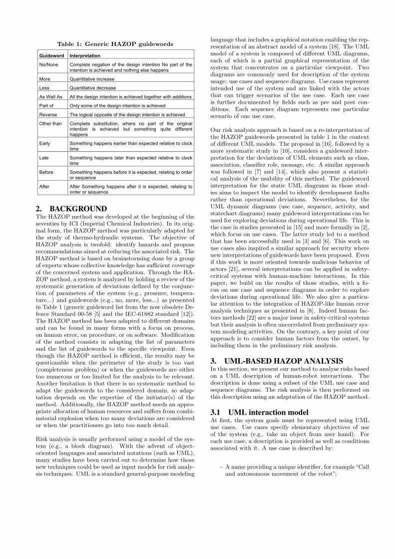
Table 1: Generic HAZOP guidewords
Guideword Interpretation
No/None Complete negation of the design intention No part of the
intention is achieved and nothing else happens
More Quantitative increase
Less Quantitative decrease
As Well As All the design intention is achieved together with additions
Part of Only some of the design intention is achieved
Reverse The logical opposite of the design intention is achieved
Other than Complete substitution, where no part of the original intention is achieved but something quite different happens
Early Something happens earlier than expected relative to clock time
Late Something happens later than expected relative to clock time
Before Something happens before it is expected, relating to order or sequence
After After Something happens after it is expected, relating to order or sequence
2. BACKGROUNDThe HAZOP method was developed at the beginning of theseventies by ICI (Imperial Chemical Industries). In its orig-inal form, the HAZOP method was particularly adapted forthe study of thermo-hydraulic systems. The objective ofHAZOP analysis is twofold: identify hazards and proposerecommendations aimed at reducing the associated risk. TheHAZOP method is based on brainstorming done by a groupof experts whose collective knowledge has sufficient coverageof the concerned system and application. Through the HA-ZOP method, a system is analyzed by holding a review of thesystematic generation of deviations defined by the conjunc-tion of parameters of the system (e.g., pressure, tempera-ture...) and guidewords (e.g., no, more, less...) as presentedin Table 1 (generic guideword list from the now obsolete De-fence Standard 00-58 [5] and the IEC-61882 standard [12]).The HAZOP method has been adapted to different domainsand can be found in many forms with a focus on process,on human error, on procedure, or on software. Modificationof the method consists in adapting the list of parametersand the list of guidewords to the specific viewpoint. Eventhough the HAZOP method is efficient, the results may bequestionable when the perimeter of the study is too vast(completeness problem) or when the guidewords are eithertoo numerous or too limited for the analysis to be relevant.Another limitation is that there is no systematic method toadapt the guidewords to the considered domain, so adap-tation depends on the expertise of the initiator(s) of themethod. Additionally, the HAZOP method needs an appro-priate allocation of human resources and suffers from combi-natorial explosion when too many deviations are consideredor when the practitioners go into too much detail.
Risk analysis is usually performed using a model of the sys-tem (e.g., a block diagram). With the advent of object-oriented languages and associated notations (such as UML),many studies have been carried out to determine how thosenew techniques could be used as input models for risk analy-sis techniques. UML is a standard general-purpose modeling
language that includes a graphical notation enabling the rep-resentation of an abstract model of a system [18]. The UMLmodel of a system is composed of different UML diagrams,each of which is a partial graphical representation of thesystem that concentrates on a particular viewpoint. Twodiagrams are commonly used for description of the systemusage: use cases and sequence diagrams. Use cases representintended use of the system and are linked with the actorsthat can trigger scenarios of the use case. Each use caseis further documented by fields such as pre and post con-ditions. Each sequence diagram represents one particularscenario of one use case.
Our risk analysis approach is based on a re-interpretation ofthe HAZOP guidewords presented in table 1 in the contextof different UML models. The proposal in [16], followed by amore systematic study in [10], considers a guideword inter-pretation for the deviations of UML elements such as class,association, classifier role, message, etc. A similar approachwas followed in [7] and [14], which also present a statisti-cal analysis of the usability of this method. The guidewordinterpretation for the static UML diagrams in those stud-ies aims to inspect the model to identify development faultsrather than operational deviations. Nevertheless, for theUML dynamic diagrams (use case, sequence, activity, andstatechart diagrams) many guideword interpretations can beused for exploring deviations during operational life. This isthe case in studies presented in [15] and more formally in [2],which focus on use cases. The latter study led to a methodthat has been successfully used in [3] and [6]. This work onuse cases also inspired a similar approach for security wherenew interpretations of guidewords have been proposed. Evenif this work is more oriented towards malicious behavior ofactors [21], several interpretations can be applied in safety-critical systems with human-machine interactions. In thispaper, we build on the results of those studies, with a fo-cus on use case and sequence diagrams in order to exploredeviations during operational life. We also give a particu-lar attention to the integration of HAZOP-like human erroranalysis techniques as presented in [8]. Indeed human fac-tors methods [22] are a major issue in safety-critical systemsbut their analysis is often uncorrelated from preliminary sys-tem modeling activities. On the contrary, a key point of ourapproach is to consider human factors from the outset, byincluding them in the preliminary risk analysis.
3. UML-BASED HAZOP ANALYSISIn this section, we present our method to analyse risks basedon a UML description of human-robot interactions. Thedescription is done using a subset of the UML use case andsequence diagrams. The risk analysis is then performed onthis description using an adaptation of the HAZOP method.
3.1 UML interaction modelAt first, the system goals must be represented using UMLuse cases. Use cases specify elementary objectives of useof the system (e.g., take an object from user hand). Foreach use case, a description is provided as well as conditionsassociated with it. A use case is described by:
- A name providing a unique identifier, for example“Calland autonomous movement of the robot”;

Table 2: Attributes, guidewords and interpretationsfor use case entity
Figure 4 - HAZOP methodology adapted from [MoD Def Stan 00-58:2000]
The conjunction attribute + guideword facilitates the generation of deviations. We adapted the guidewords of Erreur ! Source du renvoi introuvable. according to the two types of entities. They are presented hereafter in tabular form. Each table associates a list of guidewords for an attribute of one entity. An interpretation of the generic deviation is also provided in order to guide the mental process. Table 3 is the adaptation of the HAZOP guidewords for use cases, and Table 4 for sequence diagrams (which is an extension of the results of Lano et al. [LAN02]).
Entity = Use Case
Attribute Guideword Interpretation
No/none The condition is not evaluated and can have any value
Other than The condition is evaluated true whereas it is false The condition is evaluated false whereas it is true
As well as The condition is correctly evaluated but other unexpected conditions are true
Part of The condition is partially evaluated Some conditions are missing
Early
The condition is evaluated earlier than required (other condition(s) should be tested before) The condition is evaluated earlier than required for correct
synchronization with the environment
Preconditions / Postconditions /
Invariants
Late
The condition is evaluated later than required (condition(s) depending on this one should have already been tested) The condition is evaluated later than required for correct synchronization with the environment
Table 3 - Attributes, guidewords and interpretations for use case entity
- An abstract describing the interaction that occurs in
the main scenario of the use case, for example “Whencalled by the user, the robot moves from its currentposition to a position near the user”;
- A series of preconditions that must be satisfied beforethe use case can be executed, for example “The usercalled the robot” and “The robot is free from othertasks”;
- A series of postconditions that must be satisfied af-ter the use case has been completed successfully, forexample “The robot is in the user’s vicinity”;
- A series of invariants that must be fulfilled throughoutthe execution of the use case, for example “The robotdoes not collide with the environment or the user”.
UML sequence diagrams are then used to model the inter-actions between the robotic system and humans. Interac-tion between objects of the sequence diagram can be rep-resented by messages while actions of one object can berepresented using self-messages. We also use annotationsto express the types of interaction (physical contact, visualsignal, etc.) when the design is sufficiently advanced for thatto be known.
For each use case, at least one sequence diagram should bedrawn for the nominal scenario. Sequence diagrams shouldalso be drawn for the most pertinent alternative scenarios.The exceptional scenarios can be ignored as they will beidentified and analyzed during the HAZOP analysis.
This UML specification should be done as early as possiblein the development process to allow early identification ofmajor risks and consequent adaption of the design to meetthe safety requirements of the robotic system. This is possi-ble since the UML specification remains at a very high levelof abstraction. The use case diagrams define the purpose ofthe system and the sequence diagrams of interest describejust the preliminary design of the system.
3.2 HAZOP method adaptationOnce the UML interaction model is completed, the HAZOPmethod is applied by selecting elements of a diagram and
applying guidewords to them. In the Defence Standard 00-58 [5], the HAZOP analysis is the systematic identification ofevery deviation of every attribute of every entity (Figure 1).We define those terms as follows:
- An entity defines what part of the system model isunder investigation. In our case it refers to a use caseor a sequence diagram.
- An attribute refers to a physical or logical property ofan entity :
- For use cases, we choose the fields: (1) precondi-tions, (2) postconditions, and (3) invariants.
- For sequence diagrams, we identify five attributesfor each message: (1) predecessors and successorsduring the interaction, (2) message timing, (3)send and receive objects, (4) message guard con-dition and (5) message parameters.
Table 2 is the adaptation of the HAZOP guidewords for usecases, and Table 3 for sequence diagrams. An interpreta-tion of the generic deviation is also provided in order toguide the mental process. These tables were derived from acombination of the different studies presented in section 2,discussions with experts, application of the guidewords tosmall case studies, models of computation errors, and con-frontation with human error models.
Once deviations have been identified, possible consequencesand causes are analyzed. To do this, the conditions of execu-tion of the sequence diagram (e.g., environmental conditionsor human states) need to be taken into account. The nextstep is to propose hints regarding possible risk reductionmeans to prevent the occurrence of deviations or to provideprotection against their unwanted effects. One way of pre-venting the occurrence of deviations is to guarantee that afunction or functional block whose failure can give rise to thisdeviation has a high level of integrity, i.e., it is sufficientlytrustworthy to meet the safety objectives. For this, we usethe concept of Safety Integrity Levels (SILs) as defined inthe ISO/IEC61508 standard [11]. We consider that, for asafety-related function, the SIL is determined only in termsof the severity of the consequences of its failure. Hence,we used a direct mapping between severity levels and SILs.Of course, as presented in the standard, other approachescan be used to calculate a SIL. Such alternatives should beconsidered for each given project, depending on its safetyobjectives.
For some functions, it is difficult to meet the assigned SILrequirements. For example, the SIL assigned to a criticalsoftware component might require the use of stringent de-velopment methods and tools that are not capable of dealingwith the complexity of the component. Moreover, some de-viations just cannot be treated in this way. For example,the root cause of a human error cannot be mapped to afunction to which a SIL can be assigned. For these reasons,other recommendations need to be given to limit the effectsof the deviation, such as modifications of the specification,of system usage or of the human-machine interfaces.

Start Select system entity
Select entityattribute
Apply a deviation attribute + guideword
Identify possible causes and consequences of
deviation
Evaluate the risk of the deviation effect
Formulate recommendations for
prevention of deviation and protection against
consequences
More deviations to apply?
More attributes
?
More entities ?Stop
yes yes yes
no no no
Figure 1: HAZOP methodology adapted from [5]
Table 3: Attributes, guidewords and interpretations for sequence diagram entity
The final outcome of a UML-HAZOP analysis consists of alist of recommendations and a list of hazards, together withthe possible deviations leading to them. This list of hazardsmay be converted to a list of risks when the probabilities ofoccurrence of the deviations can be estimated (a risk is acombination of a harm probability and severity [13]). Thisis possible when the design is sufficiently well advanced toallow the use of other risk analysis methods such as FaultTree Analysis.
3.3 HAZOP analysis tableTo assist the HAZOP process, we propose a deviation anal-ysis table with the following columns (cf. example givenTable 51):
1. Element: the UML element on which the deviation isapplied.
2. Attribute: the considered attribute.
1For compactness, items 1 and 2 and items 6 and 7 aregrouped into single columns in this table.

3. Guideword: the applied guideword.
4. Deviation: the deviation resulting from the combina-tion of the attribute and the guideword.
6. Use Case Effect: effect at the use case level.
7. Real World Effect: possible effect in the real world.
8. Severity: rating of effect of the worst case scenario inthe real world.
9. Possible Causes: possible causes of the deviation (soft-ware, hardware, human, etc.).
10 Integrity Level Requirements: a preliminary safety in-tegrity level [11] aimed at avoiding the deviation witha sufficient level of confidence (this will lead to the ap-plication of specific fault prevention and fault removaltechniques [4]).
11. New Safety Requirements: if the deviation cannot beavoided, new requirements are specified (e.g., addi-tional fault tolerance techniques, or regulatory con-straints).
12. Remarks: explanation of analysis, additional recom-mendations, etc.
13. Hazard Numbers: real world effects are identified ashazards and assigned a number, helping the users tonavigate between results of the study and the HAZOPtables.
4. CASE STUDIESThis section presents two applications of the method. Thefirst study was performed for the PHRIENDS project [19].It analyzed the safety of a robotic mobile manipulator. Thesecond study was carried out in the framework of the MI-RAS project [17] and analyzed safety of a robotic strollingassistant. For both studies, we rated the severity of devia-tions (column 8 of the HAZOP analysis table) according tothe abbreviated injury scale of [1].
4.1 Application to a mobile robot manipula-tor
Figure 2: Example of a mobile manipulator: “con-cept omniRob” c© at Automatica 2008 exhibition –KUKA Roboter GmbH
Table 4: Description of UC4 “Take an object fromthe user’s hand”
Use case name UC4. Take an object from the user's hand
Abstract The user orders the robot to take an object from his
hand
Precondition No object in the gripper Location reachable Object can be taken
Postcondition Robot base is stopped Object in the gripper Robot arm is in transportation position
Invariant None
The first considered system is a wheel-based mobile robotwith a manipulator arm (Figure 2). The environment is aworkshop and factory with human workers. Collaborativework between a human and the robot is possible (e.g., therobot can give an object to the human). The robot is ableto navigate in a dynamic environment where there are othermobile objects (e.g., humans). Identified use cases are: Takean object from a specified location (UC1), Place an object ata specified location (UC2), Go to a location (holding or notholding an object) (UC3), Take an object from the user’shand (UC4), Give an object to the user (UC5), Abort a task(UC6), Guide the robot arm to a location (UC7), Pause andresume a task (UC8), and Physical interaction with the arm(UC9).
The five first use cases do not necessarily imply physical con-tact or even an interaction via an object; they can nonethe-less be interrupted by physically stopping the arm of therobot (UC9) in order to switch to one of the use cases UC6,UC7 or UC8. Two more use cases are Program robot (UC10)and Set up (UC11), which, although they can induce majorsafety problems, have not been considered here since theyare quite common use cases in industrial robotics and do notintroduce any novelties with respect to human-robot inter-action.
For each use case, preconditions, postconditions and invari-ants were identified, and the nominal scenario was modeledusing a sequence diagram. By way of an example, Table 4shows the description of UC4 Take an object from the user’shand and Figure 3 presents the sequence diagram of thenominal scenario of UC4. Table 5 presents an extract ofthe study of this sequence diagram. Analysis of the firstdeviation in this table leads to the requirement of a proto-col for communication between user and robot. Analysis ofthe second deviation in Table 5 leads to the identification ofa safer human-robot interaction for passing an object (Re-marks column). It is suggested that the robot’s behaviourhas to be modified.
During this study, 130 elements were analyzed leading to1694 deviations. However, only 768 deviations (45%) couldbe interpreted. The sample list of hazards presented in Ta-ble 6 is extracted from the full set of HAZOP tables in which21 hazards were identified. Due to space limitations the ta-ble shown does not contain the extra column with the listof sources of each hazard class (this column is contained inour study and in the tool presented in Section 6). This haz-

Table 5: Extract of SD4 “Take an object from the user’s hand” HAZOP analysis
Figure 3: Sequence diagram SD4 giving main sce-nario of UC4 “Take an object from the user’s hand”
ard list was checked by robotics experts of the PHRIENDSproject (KUKA Roboter GmbH). The analysis led to 18high-level recommendations, for example:
• R1. The user must be able to stop the robot at anytime by touching any part of the robot.
Table 6: Extract of identified hazards (total number21)
Hazard Hazard description1 Robot base is moving while it should not2 Robot arm is moving while it should not20 Task planning error (fault in the planner
or insufficient knowledge of the environmentor of the nature of the object)
21 Gripper speed is too slow for human/robotsynchronization
• R4. The robot and the user have to be aware of eachother: some device or means should be used to com-municate to the user the actual mode of operation ofthe robot.
• R6. Allow the user to guide not only the robot armbut the mobile base too.
4.2 Application to a robotic strolling assistantThe second considered system is a robotic strolling systemthat helps partially-disabled persons to stand up, stroll andsit down. It is intended to be used in elderly care centersby people suffering from gait and orientation problems. Thesystem consists of a wheeled base and a moving handlebar(cf. Figure 4), and is equipped with several sensors to detectphysiological parameters and the posture of the patient. Itcan also move autonomously. The preliminary design of therobot identified 11 use cases: Strolling (UC01), Standing upoperation (UC02), Sitting down operation (UC03), Balanceloss handling (UC04), Call and autonomous movement ofthe robot (UC05), End of use detection and movement toa waiting position (UC06), Positioning the robot by hand(UC07), Alarms handling (UC08), Patient profile program-ming (UC09), Patient profile learning (UC10), and Robotset-up (UC11).
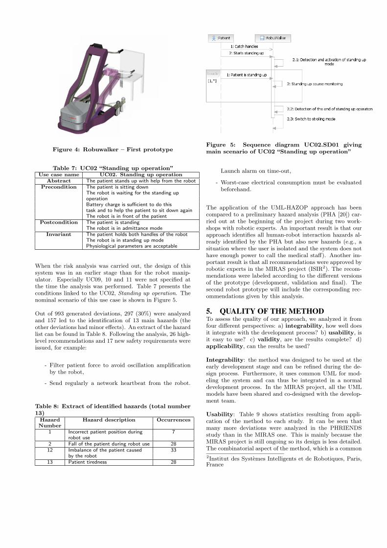
Figure 4: Robuwalker – First prototype
Table 7: UC02 “Standing up operation”Use case name UC02. Standing up operation
Abstract The patient stands up with help from the robotPrecondition The patient is sitting down
The robot is waiting for the standing upoperationBattery charge is sufficient to do thistask and to help the patient to sit down againThe robot is in front of the patient
Postcondition The patient is standingThe robot is in admittance mode
Invariant The patient holds both handles of the robotThe robot is in standing up modePhysiological parameters are acceptable
When the risk analysis was carried out, the design of thissystem was in an earlier stage than for the robot manip-ulator. Especially UC09, 10 and 11 were not specified atthe time the analysis was performed. Table 7 presents theconditions linked to the UC02, Standing up operation. Thenominal scenario of this use case is shown in Figure 5.
Out of 993 generated deviations, 297 (30%) were analyzedand 157 led to the identification of 13 main hazards (theother deviations had minor effects). An extract of the hazardlist can be found in Table 8. Following the analysis, 26 high-level recommendations and 17 new safety requirements wereissued, for example:
- Filter patient force to avoid oscillation amplificationby the robot,
- Send regularly a network heartbeat from the robot.
Table 8: Extract of identified hazards (total number13)
Hazard Hazard description OccurrencesNumber
1 Incorrect patient position during 7robot use
2 Fall of the patient during robot use 2812 Imbalance of the patient caused 33
by the robot13 Patient tiredness 28
Figure 5: Sequence diagram UC02.SD01 givingmain scenario of UC02 “Standing up operation”
Launch alarm on time-out,
- Worst-case electrical consumption must be evaluatedbeforehand.
The application of the UML-HAZOP approach has beencompared to a preliminary hazard analysis (PHA [20]) car-ried out at the beginning of the project during two work-shops with robotic experts. An important result is that ourapproach identifies all human-robot interaction hazards al-ready identified by the PHA but also new hazards (e.g., asituation where the user is isolated and the system does nothave enough power to call the medical staff). Another im-portant result is that all recommendations were approved byrobotic experts in the MIRAS project (ISIR2). The recom-mendations were labeled according to the different versionsof the prototype (development, validation and final). Thesecond robot prototype will include the corresponding rec-ommendations given by this analysis.
5. QUALITY OF THE METHODTo assess the quality of our approach, we analyzed it fromfour different perspectives: a) integrability, how well doesit integrate with the development process? b) usability, isit easy to use? c) validity, are the results complete? d)applicability, can the results be used?
Integrability: the method was designed to be used at theearly development stage and can be refined during the de-sign process. Furthermore, it uses common UML for mod-eling the system and can thus be integrated in a normaldevelopment process. In the MIRAS project, all the UMLmodels have been shared and co-designed with the develop-ment team.
Usability: Table 9 shows statistics resulting from appli-cation of the method to each study. It can be seen thatmany more deviations were analyzed in the PHRIENDSstudy than in the MIRAS one. This is mainly because theMIRAS project is still ongoing so its design is less detailed.The combinatorial aspect of the method, which is a common
2Institut des Systemes Intelligents et de Robotiques, Paris,France
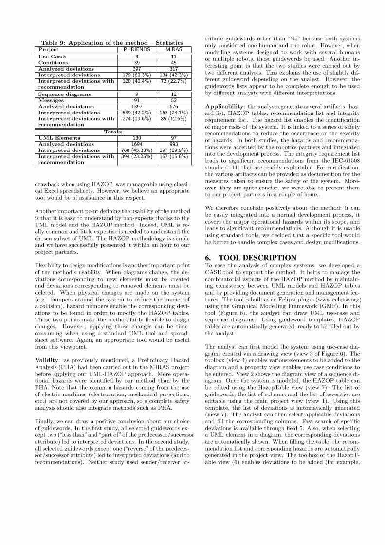
Table 9: Application of the method – StatisticsProject PHRIENDS MIRAS
Use Cases 9 11Conditions 39 45Analyzed deviations 297 317Interpreted deviations 179 (60.3%) 134 (42.3%)Interpreted deviations with 120 (40.4%) 72 (22.7%)recommendation
Sequence diagrams 9 12Messages 91 52Analyzed deviations 1397 676Interpreted deviations 589 (42.2%) 163 (24.1%)Interpreted deviations with 274 (19.6%) 85 (12.6%)recommendation
Totals:UML Elements 130 97Analyzed deviations 1694 993Interpreted deviations 768 (45.33%) 297 (29.9%)Interpreted deviations with 394 (23.25%) 157 (15.8%)recommendation
drawback when using HAZOP, was manageable using classi-cal Excel spreadsheets. However, we believe an appropriatetool would be of assistance in this respect.
Another important point defining the usability of the methodis that it is easy to understand by non-experts thanks to theUML model and the HAZOP method. Indeed, UML is re-ally common and little expertise is needed to understand thechosen subset of UML. The HAZOP methodology is simpleand we have successfully presented it within an hour to ourproject partners.
Flexibility to design modifications is another important pointof the method’s usability. When diagrams change, the de-viations corresponding to new elements must be createdand deviations corresponding to removed elements must bedeleted. When physical changes are made on the system(e.g. bumpers around the system to reduce the impact ofa collision), hazard numbers enable the corresponding devi-ations to be found in order to modify the HAZOP tables.Those two points make the method fairly flexible to designchanges. However, applying those changes can be time-consuming when using a standard UML tool and spread-sheet software. Again, an appropriate tool would be usefulfrom this viewpoint.
Validity: as previously mentioned, a Preliminary HazardAnalysis (PHA) had been carried out in the MIRAS projectbefore applying our UML-HAZOP approach. More opera-tional hazards were identified by our method than by thePHA. Note that the common hazards coming from the useof electric machines (electrocution, mechanical projections,etc.) are not covered by our approach, so a complete safetyanalysis should also integrate methods such as PHA.
Finally, we can draw a positive conclusion about our choiceof guidewords. In the first study, all selected guidewords ex-cept two (“less than”and“part of”of the predecessor/successorattribute) led to interpreted deviations. In the second study,all selected guidewords except one (“reverse”of the predeces-sor/successor attribute) led to interpreted deviations (and torecommendations). Neither study used sender/receiver at-
tribute guidewords other than “No” because both systemsonly considered one human and one robot. However, whenmodelling systems designed to work with several humansor multiple robots, those guidewords be used. Another in-teresting point is that the two studies were carried out bytwo different analysts. This explains the use of slightly dif-ferent guideword depending on the analyst. However, theguidewords lists appear to be complete enough to be usedby different analysts with different interpretations.
Applicability: the analyses generate several artifacts: haz-ard list, HAZOP tables, recommendation list and integrityrequirement list. The hazard list enables the identificationof major risks of the system. It is linked to a series of safetyrecommendations to reduce the occurrence or the severityof hazards. In both studies, the hazards and recommenda-tions were accepted by the robotics partners and integratedinto the development process. The integrity requirement listleads to significant recommendations from the IEC-61508standard [11] that are readily exploitable. For certification,the various artifacts can be provided as documention for themeasures taken to ensure the safety of the system. More-over, they are quite concise: we were able to present themto our project partners in a couple of hours.
We therefore conclude positively about the method: it canbe easily integrated into a normal development process, itcovers the major operational hazards within its scope, andleads to significant recommendations. Although it is usableusing standard tools, we decided that a specific tool wouldbe better to handle complex cases and design modifications.
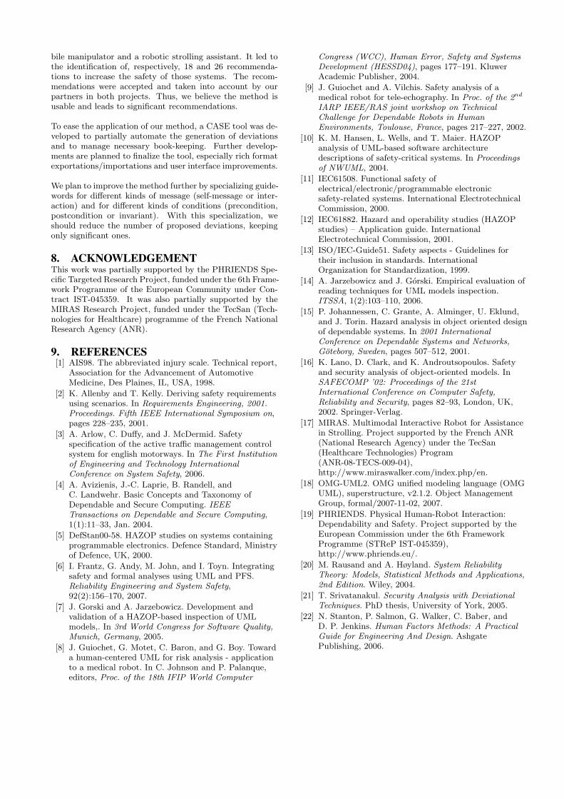
6. TOOL DESCRIPTIONTo ease the analysis of complex systems, we developed aCASE tool to support the method. It helps to manage thecombinatorial aspects of the HAZOP method by maintain-ing consistency between UML models and HAZOP tablesand by providing document generation and management fea-tures. The tool is built as an Eclipse plugin (www.eclipse.org)using the Graphical Modelling Framework (GMF). In thistool (Figure 6), the analyst can draw UML use-case andsequence diagrams. Using guideword templates, HAZOPtables are automatically generated, ready to be filled out bythe analyst.
The analyst can first model the system using use-case dia-grams created via a drawing view (view 3 of Figure 6). Thetoolbox (view 4) enables various elements to be added to thediagram and a property view enables use case conditions tobe entered. View 2 shows the diagram view of a sequence di-agram. Once the system is modeled, the HAZOP table canbe edited using the HazopTable view (view 7). The list ofguidewords, the list of columns and the list of severities areeditable using the main project view (view 1). Using thistemplate, the list of deviations is automatically generated(view 7). The analyst can then select applicable deviationsand fill the corresponding columns. Fast search of specificdeviations is available through field 5. Also, when selectinga UML element in a diagram, the corresponding deviationsare automatically shown. When filling the table, the recom-mendation list and corresponding hazards are automaticallygenerated in the project view. The toolbox of the HazopT-able view (6) enables deviations to be added (for example,

Figure 6: Main view of the CASE Tool to support the UML-HAZOP method
several deviations for the same keyword) and to export thecurrent table in the CSV (Comma Separated Values) formatreadable by spreadsheet software. Diagrams can be exportedin the image format. A report generator is currently underdevelopment.
The tool is easy to use because of its simplicity and integra-tion to a common environment. It manages the combinato-rial aspects of the HAZOP method by automatic generationof partially filled-out deviations. The method and guidewordlist can be adapted thanks to HAZOP table templates. Fur-thermore, the analysis can be exported in CSV to reuse theresults outside the tool. However, rich formats like HTMLor Excel are not yet available for exportation, which cur-rently limits the integration of our tool with other software.Rich format exportation should permit the generation of theartifacts identified in our case studies: use case list with con-ditions, sequence diagrams, list of remarks issued during theanalysis (incomplete specification, useful relation to existingnorms, etc.), list of generated hazards, HAZOP tables, listof recommendations, and list of integrity level requirements.Since we only use a partial subset of UML, the tool cannotbe used for the whole modeling process. However, impor-tation and exportation to other software like IBM Rational
Software Architect is a planned feature.
7. CONCLUSIONTo tackle safety of robotic systems, appropriate analysismethods are needed. Classic methods suffer from severallimitations: unsuited for human-robot interaction, inabilityto cope with multiple stakeholders and too late implicationin the development process. We proposed an adaptationof the HAZOP method to apply it on a subset of the Uni-fied Modeling Language. The method is particularly aimedat modeling physical human-robot interaction early in thedevelopment process. The discussions between stakehold-ers are facilitated through the use of a well-known standardformat (UML). Furthermore, since the process is quite sys-tematic, very few analysts are needed once the system ismodeled. The combinatorial aspect of the HAZOP methodremains manageable since the analysis is restricted to theuse case diagram and context sequence diagrams (showingonly actors and the system). The developed tool also helpsconsiderably in this respect since it facilitates navigationbetween generated summary listing and rough analysis con-tained in the HAZOP tables.
The method has been applied to two systems: a robotic mo-
bile manipulator and a robotic strolling assistant. It led tothe identification of, respectively, 18 and 26 recommenda-tions to increase the safety of those systems. The recom-mendations were accepted and taken into account by ourpartners in both projects. Thus, we believe the method isusable and leads to significant recommendations.
To ease the application of our method, a CASE tool was de-veloped to partially automate the generation of deviationsand to manage necessary book-keeping. Further develop-ments are planned to finalize the tool, especially rich formatexportations/importations and user interface improvements.
We plan to improve the method further by specializing guide-words for different kinds of message (self-message or inter-action) and for different kinds of conditions (precondition,postcondition or invariant). With this specialization, weshould reduce the number of proposed deviations, keepingonly significant ones.
8. ACKNOWLEDGEMENTThis work was partially supported by the PHRIENDS Spe-cific Targeted Research Project, funded under the 6th Frame-work Programme of the European Community under Con-tract IST-045359. It was also partially supported by theMIRAS Research Project, funded under the TecSan (Tech-nologies for Healthcare) programme of the French NationalResearch Agency (ANR).
9. REFERENCES[1] AIS98. The abbreviated injury scale. Technical report,
Association for the Advancement of AutomotiveMedicine, Des Plaines, IL, USA, 1998.
[2] K. Allenby and T. Kelly. Deriving safety requirementsusing scenarios. In Requirements Engineering, 2001.Proceedings. Fifth IEEE International Symposium on,pages 228–235, 2001.
[3] A. Arlow, C. Duffy, and J. McDermid. Safetyspecification of the active traffic management controlsystem for english motorways. In The First Institutionof Engineering and Technology InternationalConference on System Safety, 2006.
[4] A. Avizienis, J.-C. Laprie, B. Randell, andC. Landwehr. Basic Concepts and Taxonomy ofDependable and Secure Computing. IEEETransactions on Dependable and Secure Computing,1(1):11–33, Jan. 2004.
[5] DefStan00-58. HAZOP studies on systems containingprogrammable electronics. Defence Standard, Ministryof Defence, UK, 2000.
[6] I. Frantz, G. Andy, M. John, and I. Toyn. Integratingsafety and formal analyses using UML and PFS.Reliability Engineering and System Safety,92(2):156–170, 2007.
[7] J. Gorski and A. Jarzebowicz. Development andvalidation of a HAZOP-based inspection of UMLmodels,. In 3rd World Congress for Software Quality,Munich, Germany, 2005.
[8] J. Guiochet, G. Motet, C. Baron, and G. Boy. Towarda human-centered UML for risk analysis - applicationto a medical robot. In C. Johnson and P. Palanque,editors, Proc. of the 18th IFIP World Computer
Congress (WCC), Human Error, Safety and SystemsDevelopment (HESSD04), pages 177–191. KluwerAcademic Publisher, 2004.
[9] J. Guiochet and A. Vilchis. Safety analysis of amedical robot for tele-echography. In Proc. of the 2nd
IARP IEEE/RAS joint workshop on TechnicalChallenge for Dependable Robots in HumanEnvironments, Toulouse, France, pages 217–227, 2002.
[10] K. M. Hansen, L. Wells, and T. Maier. HAZOPanalysis of UML-based software architecturedescriptions of safety-critical systems. In Proceedingsof NWUML, 2004.
[11] IEC61508. Functional safety ofelectrical/electronic/programmable electronicsafety-related systems. International ElectrotechnicalCommission, 2000.
[12] IEC61882. Hazard and operability studies (HAZOPstudies) – Application guide. InternationalElectrotechnical Commission, 2001.
[13] ISO/IEC-Guide51. Safety aspects - Guidelines fortheir inclusion in standards. InternationalOrganization for Standardization, 1999.
[14] A. Jarzebowicz and J. Gorski. Empirical evaluation ofreading techniques for UML models inspection.ITSSA, 1(2):103–110, 2006.
[15] P. Johannessen, C. Grante, A. Alminger, U. Eklund,and J. Torin. Hazard analysis in object oriented designof dependable systems. In 2001 InternationalConference on Dependable Systems and Networks,Goteborg, Sweden, pages 507–512, 2001.
[16] K. Lano, D. Clark, and K. Androutsopoulos. Safetyand security analysis of object-oriented models. InSAFECOMP ’02: Proceedings of the 21stInternational Conference on Computer Safety,Reliability and Security, pages 82–93, London, UK,2002. Springer-Verlag.
[17] MIRAS. Multimodal Interactive Robot for Assistancein Strolling. Project supported by the French ANR(National Research Agency) under the TecSan(Healthcare Technologies) Program(ANR-08-TECS-009-04),http://www.miraswalker.com/index.php/en.
[18] OMG-UML2. OMG unified modeling language (OMGUML), superstructure, v2.1.2. Object ManagementGroup, formal/2007-11-02, 2007.
[19] PHRIENDS. Physical Human-Robot Interaction:Dependability and Safety. Project supported by theEuropean Commission under the 6th FrameworkProgramme (STReP IST-045359),http://www.phriends.eu/.
[20] M. Rausand and A. Høyland. System ReliabilityTheory: Models, Statistical Methods and Applications,2nd Edition. Wiley, 2004.
[21] T. Srivatanakul. Security Analysis with DeviationalTechniques. PhD thesis, University of York, 2005.
[22] N. Stanton, P. Salmon, G. Walker, C. Baber, andD. P. Jenkins. Human Factors Methods: A PracticalGuide for Engineering And Design. AshgatePublishing, 2006.