Hazard analysis of human–robot interactions with HAZOP–UML
36
HAL Id: hal-01271565 https://hal.archives-ouvertes.fr/hal-01271565 Submitted on 9 Feb 2016 HAL is a multi-disciplinary open access archive for the deposit and dissemination of sci- entific research documents, whether they are pub- lished or not. The documents may come from teaching and research institutions in France or abroad, or from public or private research centers. L’archive ouverte pluridisciplinaire HAL, est destinée au dépôt et à la diffusion de documents scientifiques de niveau recherche, publiés ou non, émanant des établissements d’enseignement et de recherche français ou étrangers, des laboratoires publics ou privés. Hazard analysis of human–robot interactions with HAZOP–UML Jérémie Guiochet To cite this version: Jérémie Guiochet. Hazard analysis of human–robot interactions with HAZOP–UML. Safety Science, Elsevier, 2016, 84, pp. 225-237. 10.1016/j.ssci.2015.12.017. hal-01271565
Transcript of Hazard analysis of human–robot interactions with HAZOP–UML

HAL Id: hal-01271565https://hal.archives-ouvertes.fr/hal-01271565
Submitted on 9 Feb 2016
HAL is a multi-disciplinary open accessarchive for the deposit and dissemination of sci-entific research documents, whether they are pub-lished or not. The documents may come fromteaching and research institutions in France orabroad, or from public or private research centers.
L’archive ouverte pluridisciplinaire HAL, estdestinée au dépôt et à la diffusion de documentsscientifiques de niveau recherche, publiés ou non,émanant des établissements d’enseignement et derecherche français ou étrangers, des laboratoirespublics ou privés.
Hazard analysis of human–robot interactions withHAZOP–UML
Jérémie Guiochet
To cite this version:Jérémie Guiochet. Hazard analysis of human–robot interactions with HAZOP–UML. Safety Science,Elsevier, 2016, 84, pp. 225-237. �10.1016/j.ssci.2015.12.017�. �hal-01271565�

Hazard analysis of human-robot interactions with
HAZOP-UML
Jeremie Guiochet
University of Toulouse, LAAS-CNRS, Toulouse, France
Abstract
New safety critical systems are about to appear in our everyday life: advancedrobots able to interact with humans and perform tasks at home, in hospi-tals, or at work. A hazardous behavior of those systems, induced by failuresor extreme environment conditions, may lead to catastrophic consequences.Well-known risk analysis methods used in other critical domains (e.g., avion-ics, nuclear, medical, transportation), have to be extended or adapted dueto the non-deterministic behavior of those systems, evolving in unstructuredenvironments. One major challenge is thus to develop methods that can beapplied at the very beginning of the development process, to identify hazardsinduced by robot tasks and their interactions with humans. In this paper wepresent a method which is based on an adaptation of a hazard identificationtechnique, HAZOP (Hazard Operability), coupled with a system descriptionnotation, UML (Unified Modeling Language). This systematic approach hasbeen applied successfully in research projects, and is now applied by robotmanufacturers. Some results of those studies are presented and discussed toexplain the benefits and limits of our method.
Keywords: Hazard identification, Risk analysis, Robot safety, HAZOP,UML
1. Introduction
Besides the developments of well-known safety critical systems in aero-nautics or transportation, new systems are about to appear in our everyday
Email address: [email protected] (Jeremie Guiochet)URL: homepages.laas.fr/guiochet (Jeremie Guiochet)
Preprint submitted to Safety Science February 9, 2016

life: robots at home, at work, or in the hospitals (Royakkers and van Est,2015). Such systems, will interact with users, and execute tasks in the vicinityor even in physical contact with humans. Hence, a failure of such complexsystems may lead to catastrophic consequences for users which is a majorobstacle to their deployment in real life. Most safety analysis techniquescoming from the dependability (Avizienis et al., 2004) or risk management(ISO31000, 2009) domains could be used for such systems, but some speci-ficities of robots limit their efficiency. For instance, the fact that robots movein unstructured and unknown environments makes the verification and vali-dation (mainly through testing) non sufficient (it is impossible to guaranteethat all main scenarios have been tested); the presence of users and com-plex non deterministic software (with decisional mechanisms) limit the useof quantitative risk analysis techniques; classical hazard analysis techniquesare also not adapted to the complexity of human-robot interactions. Littlework has been done about risk analysis for such systems, although it is amajor challenge for robot certification (Mitka et al., 2012). Many roboticsstudies about estimation and treatment of collision risks exist (many refer-ences presented by Haddadin (2014)), but few are on risk analysis methods(Dogramadzi et al., 2014). The safety community has rarely addressed thisissue, whereas we have been working on this for a decade (Guiochet andVilchis, 2002; Guiochet et al., 2004).
Some robot manufacturers use directives (2006/42/EC, 2006) or stan-dards (ISO13849-1, 2006) dedicated to machines, but they are not completelyapplicable, particularly when there is a human-robot physical interaction.Generic standards like IEC61508-5 (2010), are also hardly applicable due touncertainties in the robot behavior (in this standard, fault correction throughartificial intelligence is not recommended for safety integrity level SIL2 toSIL4). More recently, the standard ISO10218-1 (2011) for industrial robotsthat might share their workspace with humans, has been completed by theISO13482 (2014). It is also important to note that such standards, do notcover other application domain robots. For instance, in the medical field,there is no robotic-specific standard, and the robots are considered as activemedical devices such as defined in the 93/42/EEC (1993), and covered byISO/FDIS14971 (2006) for risk management. In all those standards, classicrisk management and design recommendations are proposed, but no specificguidelines for risk analysis techniques are presented.
To cope with the previous issues, we suggest a hazard identification tech-nique with the following objectives:
2

1. applicable from the very beginning of the development process
2. includes human activity as a source of hazard
3. provides guidance for analysts with list of guide words
4. focuses on operational hazards, i.e., hazards linked with the robot tasksand interactions
Among risk analysis techniques, the most widely used are Preliminary HazardAnalysis (PHA), Hazard Operability Analysis (HAZOP), Fault Tree Anal-ysis (FTA), and Failure Mode, Effects, and Criticality Analysis (FMECA).The two first may be applied as hazard analysis at the very early steps of adevelopment process, whereas FTA and FMECA are more dedicated to ad-vanced steps, focusing more on reliability aspects. Thus, we chose to base ourmethod on HAZOP, and to combine it with the system modeling languageUML (Unified Modeling Language). This method developed at LAAS (Guio-chet et al., 2010; Martin-Guillerez et al., 2010; Guiochet et al., 2013), has beensuccessfully applied in several French and European projects (PHRIENDS,2006-2009; SAPHARI, 2011-2015; MIRAS, 2009-2013) in collaboration withrobot manufacturers (KUKA Robotics, AIRBUS Group and Robosoft). Thispaper synthesizes for the first time our work on HAZOP-UML, and proposesan analysis of the applications in these projects.
The remainder of this paper is structured as follows. Section 2 providesbackground on UML and HAZOP. In Section 3, we present the HAZOP-UML method, and in Section 4, results of several experiments are analyzedand discussed. In Section 5, related work on model-based safety analysisis compared to our approach. We conclude in Section 6 by outlining thebenefits and limits of HAZOP-UML, and listing some future directions.
2. Background
2.1. Unified Modeling Language
UML (Unified Modeling Language) is a graphical notation, widely usedin software and system engineering domains to support early steps of thedevelopment process. Its specification is available on the Object ManagementGroup UML page1. The current version (UML 2), has thirteen diagrams,that could be classified in static diagrams (e.g., class diagram) and dynamicdiagrams (e.g., use case, sequence and state machine diagrams). UML is
1www.uml.org : accessed 2015-05-15
3

4.4 Analyse et évaluation des risques 103
Figure 4.4 – Le premier prototype (Robosoft) (à gauche) et le deuxième (ISIR)(à droite)
extrait d’une table HAZOP telle que nous l’avons déployée est donné Figure 4.7. Cetteétude a donné lieu à une liste de dangers présentée Figure 4.9, que l’on a extrait des tablesHAZOP. Pour chaque danger nous avons également utilisé des références vers les lignes destables HAZOP induisant le danger. Ce travail permet ainsi d’avoir une traçabilité entreles causes et les conséquences, et peut s’avérer très utile si l’on souhaite utiliser d’autrestechniques d’analyse du risque comme les arbres de fautes ou une AMDEC par exemple.
La liste est donnée ci-dessous :HN01 Posture incorrecte du patient pendant l’utilisation du robot (penché en avant ou
en arrière)HN02 Chute du patient pendant l’utilisation du robot (comme pour un déambulateur
classique), soit au sol, soit sur le robot lui-mêmeHN03 Arrêt total du robot pendant l’utilisation (absence d’énergie), rendant impossible
toute action du robotHN04 Chute du patient sans alarme ou avec alarme tardiveHN05 Problème physiologique du patient sans alarme ou avec alarme tardiveHN06 Chute du patient provoquée par le robot (mouvement non désiré du robot)HN07 Incident détecté mais défaut de passage en mode sûr ; le robot continue à se
déplacer alors qu’il a un déséquilibre, une chute ou une fatigue du patientHN08 Le robot coince un membre du patient entre 2 parties du robot ou entre le robot
et un objet fixeHN09 Collision entre le robot (ou partie du robot) et le patient
Figure 1: MIRAS robot prototype during clinical investigation
a language, and not a method, as it is not specified in which chronologicalorder each diagram must be used. But, use cases and sequence diagrams aretypically used at the beginning of any project development. State machinediagrams are also widely used in reactive systems as robot controllers. Hence,we will present those three diagrams, focusing only in the elements we willuse for our approach. One main pitfall using this language is to mix differentlevels of details in the same diagram. For instance, mixing some high levelspecifications with implementation constraints on the same diagram is errorprone and also not recommended for the safety analysis. This is why we alsoput forward in this paper some modeling rules to avoid this pitfall and toguide the analysts.
As a running example, we will use some models of the case study MIRAS(2009-2013), an assistive robot presented Figure 1, for standing up, sittingdown and walking, and also capable of health-state monitoring of the pa-tients. It is designed to be used in elderly care centers by people sufferingfrom gait and orientation problems where a classic wheeled walker (or “rolla-tor”), is not sufficient for patient autonomy. The robotic rollator is composedof a mobile base and a moving handlebar.
Use case diagrams. This diagram is the basic requirement UML model, pre-senting the system to analyse, the actors communicating with it, and theobjectives for the use of the system: the use cases. The example of Figure 2only presents a subset of the complete use case diagram (15 use cases), andthe two involved actors. In this diagram, the proposed services are to helpthe patient to stand up (UC02), deambulate (UC01), and sit down (UC03).The system is also able to detect physiological issues and trigger an alarm(patient heartbeat and fatigue, in UC08). We also represent that the systemoffers the profile learning facility (UC10). In some projects using UML the
4

Patient
MIRAS Robot
UC01Strolling UC02
Standing up operation
Medical Staff
UC03Sitting down
operation
UC08Alarm
Handling
UC10Patient profile
learning
Actor
Use case
Association
Studied system boundary
Figure 2: Extract of MIRAS use case diagram from Guiochet et al. (2013)
mechanical part of a robot is represented as a UML actor, and the systemboundary (the box around use cases) defines the robot controller (includingsoftware and hardware). We do not recommend using such an approach toperform the hazard identification, indeed, the complete system has to bestudied as a whole.
This diagram provides an expressive and simple mean to communicate be-tween developers, analysts and users. This graphical representation is alwayscompleted with a textual description as in Figure 3. Important informationsuch pre and post conditions, and non-functional requirements are included.Use case diagram only represents functional requirements. Textual descrip-tion of the normal, alternative and exception flows may also be presentedwith sequence diagrams as presented hereafter.
In the UML OMG standard, some relations may exist between use cases(mainly the relations extend and include) but we recommend not to usethem, as they often lead to misunderstandings and to an unclear applicationof the HAZOP-UML method. In order to prepare the HAZOP-UML study,an extract from the use case textual description should be done, with only thepre and post conditions, and also the invariants coming from safety propertiesin the “Non functional requirements” category. An example of such a tableis given in Figure 4 for the UC02 of the MIRAS running example.
5

Use Case Name [Name of the use case] Actors [An actor is a person or other entity external to the system being
specified who interacts with the system and performs use cases to accomplish tasks]
Preconditions [Activities that must take place, or any conditions that must be true, before the use case can be started]
Normal Flow
Description [User actions and system responses that will take place during execution of the use case under normal, expected conditions.]
Postconditions
[State of the system at the conclusion of the use case execution with a normal flow (nominal)]
Alternative flows and exceptions
[Major alternative flows or exceptions that may occur in the flow of event]
Non functional requirements
[All non-functional requirement: e.g., dependability (safety, reliability, etc.), performance, ergonomic]
Figure 3: Use case textual description template
Use case name UC02. Standing up operation
Abstract The patient stands up with the help of the robot
Precondition The patient is sitting down
The robot is waiting for the standing up
operation
Battery charge is sufficient to do this task and to
help the patient to sit down
The robot is in front of the patient
Postcondition The patient is standing up
The robot is in admittance mode
Invariant The patient holds both handles of the robot
The robot is in standing up mode
Physiological parameters are acceptable
Figure 4: UC02 use case textual description with pre,post conditions and invariant
6
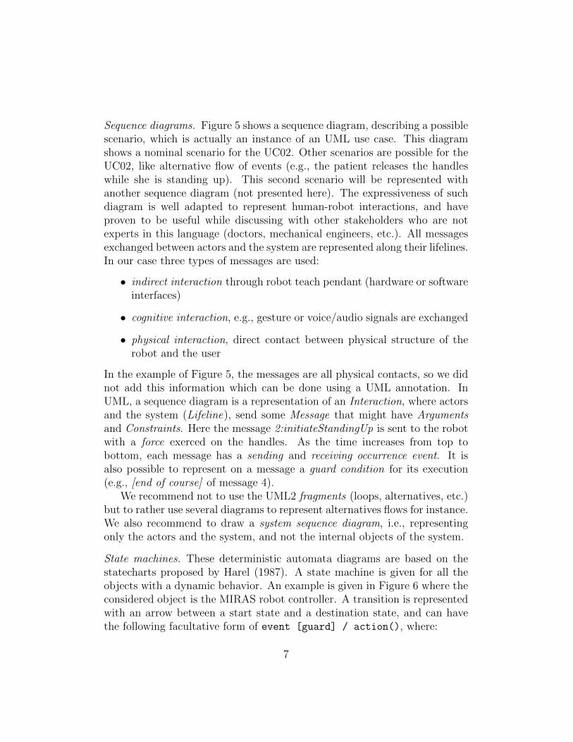
Sequence diagrams. Figure 5 shows a sequence diagram, describing a possiblescenario, which is actually an instance of an UML use case. This diagramshows a nominal scenario for the UC02. Other scenarios are possible for theUC02, like alternative flow of events (e.g., the patient releases the handleswhile she is standing up). This second scenario will be represented withanother sequence diagram (not presented here). The expressiveness of suchdiagram is well adapted to represent human-robot interactions, and haveproven to be useful while discussing with other stakeholders who are notexperts in this language (doctors, mechanical engineers, etc.). All messagesexchanged between actors and the system are represented along their lifelines.In our case three types of messages are used:
• indirect interaction through robot teach pendant (hardware or softwareinterfaces)
• cognitive interaction, e.g., gesture or voice/audio signals are exchanged
• physical interaction, direct contact between physical structure of therobot and the user
In the example of Figure 5, the messages are all physical contacts, so we didnot add this information which can be done using a UML annotation. InUML, a sequence diagram is a representation of an Interaction, where actorsand the system (Lifeline), send some Message that might have Argumentsand Constraints. Here the message 2:initiateStandingUp is sent to the robotwith a force exerced on the handles. As the time increases from top tobottom, each message has a sending and receiving occurrence event. It isalso possible to represent on a message a guard condition for its execution(e.g., [end of course] of message 4).
We recommend not to use the UML2 fragments (loops, alternatives, etc.)but to rather use several diagrams to represent alternatives flows for instance.We also recommend to draw a system sequence diagram, i.e., representingonly the actors and the system, and not the internal objects of the system.
State machines. These deterministic automata diagrams are based on thestatecharts proposed by Harel (1987). A state machine is given for all theobjects with a dynamic behavior. An example is given in Figure 6 where theconsidered object is the MIRAS robot controller. A transition is representedwith an arrow between a start state and a destination state, and can havethe following facultative form of event [guard] / action(), where:
7

:Patient
: MIRASRobot
1: catchHandles()
2: initiateStandingUp(force)2.1 : activateStandingUpMode()
3. patientStandingUp()3.1 : courseAssistance()
4 : [end of course] activateStrollingMode
Time
sd Standing up nominal
1.1 : detectCatching()
Lifeline
Message signature
Message argument
(Sending) OccurrenceSpecification
(Receiving) OccurrenceSpecification Interaction constraint
(Guard condition)
Interaction
Figure 5: Sequence diagram for the nominal scenario of UC01: Standing up operation
PhysicalInteractionAssistance
Idle
Alarm
StandingUp
Strolling
SittingDownBalanceManagement
H
physiological problem / sendAlarm()
[two handles catched] initStandingUp
release of handles
end of sitting down
end of course
end of strolling
end of unbalanced
unbalance
medical staff intervention
Initial state
Final state
Event Action
State
Super stateCondition
History operator
Figure 6: Simplified version of MIRAS state machine
8

• event is the trigger element of the transition, which could be:
– signal event : asynchronous external event (e.g., button pressed,voice command)
– call event : reception of an operation called by another object ofthe system
– change event : a change of a boolean variable based on the esti-mation of a system variable
– temporal event (after or when): expired duration after(<duration>),or absolute time when(date=<date>)
• guard is a condition estimated only if the event occurs
• action is a list of actions performed instantly when the transition istriggered
In this method we use state diagrams to specify at the beginning of aproject, the different operational modes of the robot. This diagram is alsouseful for the detailed design and implementation of the robot controller,which is out of the scope of this paper.
2.2. HAZOP
HAZOP (HAZard OPerability) is a collaborative hazard identificationtechnique, developed in the 70’s, and is widely used in the process industries.It is now standardized by the standard IEC61882 (2001). Its success mainlylies in its simplicity and the possibility to apply it at the very beginning of thedevelopment process. It is also adaptable to the formalism used to describea system as presented in the standard DefStan00-58 (2000). HAZOP doesnot consider failure modes as FMECA, but potential deviations of the mainparameters of the process. For each part of the system, the identification ofthe deviation is systematically done with the conjunction of:
• system parameters, e.g., in the case of an industrial process : temperature,pressure, flow, etc.
• guide words like: No, More, Less or Reverse
The role of the guide word is to stimulate imaginative ideas and initiatediscussions. A proposed list of guide words is given in Figure 7. For instance,we can have the following conjunctions (e.g., for a chemical process):
9

Guideword Interpretation
No/None Complete negation of the design intention / No part of the intention is achieved and nothing else happens
More Quantitative increase
Less Quantitative decrease
As Well As All the design intention is achieved together with additions
Part of Only some of the design intention is achieved
Reverse The logical opposite of the design intention is achieved
Other than Complete substitution, where no part of the original intention is achieved but something quite different happens
Early Something happens earlier than expected relative to clock time
Late Something happens later than expected relative to clock time
Before Something happens before it is expected, relating to order or sequence
After After Something happens after it is expected, relating to order or sequence
Figure 7: Guide words list adapted from IEC61882 (2001)
• Temperature ⊗ More → Temperature too high
• Flow ⊗ Reverse → Product flow reversal
For each deviation, the procedure is then to investigate causes, consequencesand protection, and produce document usually in a table form (similar toFMECA), with columns like: Guide word, Element, Deviation, Possiblecauses, Consequences, Safeguards, Comments, Actions required, etc.
Even though the HAZOP method has proved to be efficient, the resultsmay be questionable when the boundary of the study is too vast or not welldefined, or when the guide words are either too numerous or too limited forthe analysis to be relevant. Another limitation is that there is no systematicmethod to adapt the guide words to the considered domain, so adaptationdepends on the expertise of the initiators of the method. Additionally, theHAZOP method needs the allocation of human resources and suffers fromcombinatorial explosion when too many deviations are considered or whenthe analysts go into too much details. Hence, the success of a HAZOP studydepends greatly on the ability of the analyst and the interactions betweenteam members. The choice of the considered “system parameters”, is of highimportance, because all the study relies on it. The HAZOP-UML methodproposed in this paper is aimed at providing more guidance to analysts to
10

identify which parameters they have to consider.
3. HAZOP-UML
One main issue when applying HAZOP is to identify the system param-eters. We propose to use UML to partition and describe the system. Theconsidered parameters will be then some elements of the UML diagrams. Inthis section we will give guidelines to identify those parameters, and the asso-ciated guide words to identify possible deviations. This work is the result ofseveral applications and refinement, and may also be completed or modifiedby the analysts. Even if our objective is to propose a systematic approach, itis important to note that HAZOP-UML does not identify all hazards. Firstbecause no single hazard identification technique is actually capable of find-ing all the hazards (Cantrell and Clemens, 2009), and also because we willfocus on the identification of the operational hazards, i.e., hazards linked tothe human-robot interactions, through dynamic models of the system.
As already presented, we propose to focus on the three main dynamicUML diagrams: use case, sequence and state diagrams. For those diagrams,some generic deviations are presented in Section 3.1. The whole process isthen introduced in Section 3.2, and Section 3.3 presents a prototype of a toolfor HAZOP-UML.
3.1. Guide words
Instead of using the term “parameter” usually used in HAZOP studies,entities and attributes of UML elements are introduced in this section. Thenfor each element, a generic interpretation for a deviation is proposed. Thisanalysis is based on the UML metamodel (OMG-UML2, 2007). The selectedUML entities are : use case, message, state machine.
3.1.1. Guide words for use cases
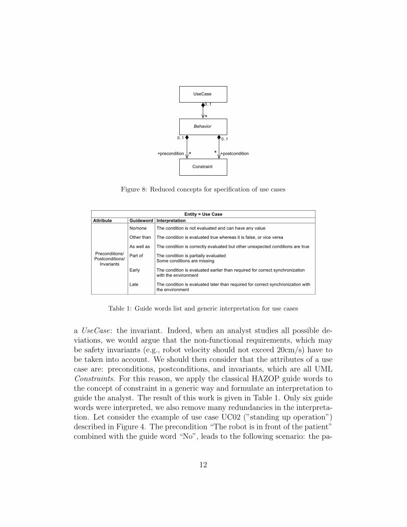
Figure 8 presents an extract from the UML metamodel, focusing on a usecase. The UML class diagram notation is used to represent this metamodel.This diagram specifies that a use case may be composed of 0 to several (notedas “*”) Behaviors. Indeed, a use case is usually composed of a nominal behav-ior (or nominal scenario), and several exceptions. Each Behavior may have0 to several Constraints, which are pre and post conditions. As introducedin section 2.1, we add to this metamodel one constraint to the Behavior of
11
Behavior
UseCase
Constraint
+precondition +postcondition**
0..10..1
0..1
*
Figure 8: Reduced concepts for specification of use cases
Entity = Use Case
Attribute Guideword Interpretation
Preconditions/ Postconditions/
Invariants
No/none The condition is not evaluated and can have any value
Other than The condition is evaluated true whereas it is false, or vice versa
As well as The condition is correctly evaluated but other unexpected conditions are true
Part of
The condition is partially evaluated Some conditions are missing
Early The condition is evaluated earlier than required for correct synchronization with the environment
Late The condition is evaluated later than required for correct synchronization with the environment
Table 1: Guide words list and generic interpretation for use cases
a UseCase: the invariant. Indeed, when an analyst studies all possible de-viations, we would argue that the non-functional requirements, which maybe safety invariants (e.g., robot velocity should not exceed 20cm/s) have tobe taken into account. We should then consider that the attributes of a usecase are: preconditions, postconditions, and invariants, which are all UMLConstraints. For this reason, we apply the classical HAZOP guide words tothe concept of constraint in a generic way and formulate an interpretation toguide the analyst. The result of this work is given in Table 1. Only six guidewords were interpreted, we also remove many redundancies in the interpreta-tion. Let consider the example of use case UC02 (”standing up operation”)described in Figure 4. The precondition “The robot is in front of the patient”combined with the guide word “No”, leads to the following scenario: the pa-
12

Message
Interaction
OccurrenceSpecification
GeneralOrdering
LifeLine*
+toBefore+toAfter
+sendEvent
+receiveEvent
0..1
0..10..1
0..1
1
*
NamedElement
ValueSpecification
+argument
+signature
0..1
*
0..1
*
InteractionConstraint
Constraint
1 *
1
*
+guard
1
1
*
1
*
+after+before
Figure 9: Reduced metamodel for interactions in UML (sequence diagrams) extractedfrom OMG-UML2 (2007)
tient tries to standup while the robot is not properly positioned. This mightinduce excessive effort for the patient and a fall which is catastrophic in ourcase study. If we consider this use case, with 9 conditions and 6 guide words,this leads to 54 possible deviations. Moreover, the interpretation of a guideword may change from an analyst to another. Nevertheless, the objective isto eventually identify all hazards, and the original guide word used for theidentification is of no real importance.
3.1.2. Guide words for sequence diagrams
Sequence diagrams are one of the graphical representation of the Interac-tion UML concept. It is composed of Lifelines exchanging Messages. Thisis represented in the simplified metamodel in Figure 9. This metamodel ex-tracted from OMG-UML2 (2007) has very little differences with the version(OMG-UML2, 2011), so we kept this representation which is simpler, andexpressive enough for its use in HAZOP-UML. Based on this metamodel, wedefine five attributes for the Message:
1. General Ordering: the general order of the messages within the inter-action
2. Send/receive event timing: event related to the clock time
3. Lifelines: send and receiving lifelines of a message
4. Interaction Constraint: guard condition on a message
13

5. Message argument: parameters of a message
Other elements of the metamodel have not been considered, as we did notfind any possible deviation or we intentionally avoid to consider them becausethey would have produced redundant possible deviations (interested readermay find more about UML interaction fragments in OMG-UML2 (2011).The resulting table for the generic deviations and their interpretation is givenin Table 2. In tOMG-UML2 (2011) the following explanation is given: “AGeneralOrdering represents a binary relation between two OccurrenceSpec-ifications, to describe that one OccurrenceSpecification must occur beforethe other in a valid trace. This mechanism provides the ability to definepartial orders of OccurrenceSpecifications that may otherwise not have aspecified order.” This could be interpreted as the fact that in some diagramsa GeneralOrdering relation can be added as a constraint. But in a sequencediagram, the physical position of the message already specifies an order for avalid trace. Hence, in our approach, we will interpret a sequence diagram asa valid trace, i.e., with a valid specified ordering of the message. This traceis descriptive (and not prescriptive like the state machine), but changing theordering may lead to hazardous interactions.
3.1.3. Guide words for state machines
The same approach was used for the state machines. This diagram canalso be used for detailed system design, which may lead to a combinatory ex-plosion for the HAZOP analysis. Hence, we reduced the number of conceptsto a very simple version as presented in Figure 10. Note that we replacedin this model the original class Behavior by Action. Actually, in UML anaction is the fundamental unit of behavior specification, which can be asso-ciated to a state or a transition. We only consider in this method the actionon transitions, which is sufficient to express relevant behavior. Of course,our proposal could be extended to the complete state machine metamodel,to identify all possible deviation at design time, but this is out of the scopeof our method.
According to this metamodel, the resulting table for possible deviationsis given in Table 3. In order to provide more guidance, we also point out inthis table if the transition is triggered or not for some deviations.
3.2. HAZOP-UML process and outputs
According to the previous tables, the process to perform HAZOP-UMLis the following procedure: for each entity, for each attribute, for each guide
14

Entity = Message
Attribute Guideword Interpretation
General Ordering
No Message is not sent Other than Unexpected message is sent As well as Message is sent as well as another message More than Message sent more often than intended Less than Message sent less often than intended Before Message sent before intended After Message sent after intended Part of Only a part of a set of messages is sent Reverse Reverse order of expected messages
Send/receive event timing
As well as Message sent at correct time and also at incorrect time Early Message sent earlier than intended time Later Message sent later than intended time
Lifelines (receiving and
sending objects)
No Message sent to but never received by intended object Other than Message sent to wrong object As well as Message sent to correct object and also an incorrect object Reverse Source and destination objects are reversed More Message sent to more objects than intended Less Message sent to fewer objects than intended
Interaction Constraint
(Message guard condition)
No/none The condition is not evaluated and can have any value Other than The condition is evaluated true whereas it is false, or vice versa As well as The condition is well evaluated but other unexpected conditions are true Part of Only a part of condition is correctly evaluated Late The condition is evaluated later than correct synchronization with the
environment
Message arguments
(Parameters)
No/None Expected parameters are never set / returned More Parameters values are higher than intended Less Parameters values are lower than intended As Well As Parameters are also transmitted with unexpected ones Part of Only some parameters are transmitted
Some parameters are missing Other than Parameter type / number are different from those expected by the receiver
Table 2: Guide words list and generic interpretation for sequence diagram messages
Transition
State
+source +target11
**
Constraint
Action
0..1*Event
*0..1
*0..1
Figure 10: Adapted UML metamodel of state machine
15

Entity = State machine
Attribute Guideword Interpretation
Destination state
Other than The transition leads to another state than expected
Transition No/none The transition is not triggered when intended
Never The transition is not triggered because the event never occurs or the condition is never met
Event No/none The transition is triggered while the event does not occur
Other than transition not triggered : the transition is not triggered when the event occurs transition triggered : the transition is triggered when another event occurs
Condition
No/none The condition is not evaluated and can have any value, the transition is triggered
Other than transition not triggered : the condition is evaluated false whereas it is true, the transition is not triggered transition triggered : the condition is evaluated true whereas it is false, the transition is triggered
As well as The condition is well evaluated but other unexpected conditions are true, the transition is triggered
Part of Only a part of condition is correctly evaluated, the transition is triggered
Early The condition is evaluated sooner than required, the transition is triggered
Late The condition is evaluated later than required, the transition is triggered
Action
No/none The transition is not triggered, there is no action
Other than The transition is triggered but an action other than intended takes place
As well as The transition is triggered, the action as well as an unexpected action take place
Part of The transition is triggered but only a part of action takes place
Early The transition is triggered but the action takes place sooner than correct synchronization with the environment
Late The transition is triggered but the action takes place later than correct synchronization with the environment
More The transitions is triggered but the result of the action, if quantifiable, is too high
Less The transitions is triggered but the result of the action, if quantifiable, is too low
Table 3: Guide words list and generic interpretation for state machines
16

Start Select system entity
Select entityattribute
Apply a deviation attribute + guideword
Identify possible causes and consequences of
deviation
Evaluate the risk of the deviation effect
Formulate recommendations for
prevention of deviation and protection against
consequences
More deviations to apply?
More attributes
?
More entities ?Stop
yes yes yes
no no no
Figure 11: HAZOP-UML process
words, identify one or several possible deviations and analyse it (them). Agraphical view is given in Figure 11. The analysis of the deviation mayinclude the identification of possible causes and consequences. Dependingon the project, it is also possible to evaluate the risk (consequence of thedeviation effect, and likelihood of the considered deviation). Nevertheless,this information is usually too complex or impossible to obtain. On thecontrary, such analysis always includes identification of recommendations totreat the deviation or its causes or it consequences (prevention and protectionmeans). To establish such a study, the columns of a table as in Figure 12 aregiven hereafter:
1. Entity: the UML element on which the deviation is applied (here UC02is the same for all the table so it is in the head of the table)
2. Line number: for traceability (UCx.line number)3. Attribute: the considered attribute (e.g., a use case precondition)4. Guide word: the applied guide word5. Deviation: the deviation resulting from the combination of the entity
attribute and the guide word based on Tables 1, 2 and 3.6. Use Case Effect: effect at the use case level.7. Real World Effect: possible effect in the real world.8. Severity: rating of effect of the worst case scenario in the real world.9. Possible Causes: possible causes of the deviation (software, hardware,
human, etc.).
17

Date: Prepared by:
Revised by:
Line Number Attribute Guideword Deviation Use Case
EffectReal World
Effect Severity Possible Causes
Safety Recommandation Remarks Hazard
Num.
UC02.15
Battery charge is
sufficient to do this task and to help
the patient to sit down
(precond)
No/none
Battery charge is too low but the robot starts the standing up operation
The robot interrupts its movement
(standing up or walking)
Loss of balance or fall of the patient
Serious
HW/SW Failure
Specification error
Worst-case electrical
consumption must be
evaluated beforehand. Take the lower bound of the battery
charge estimation
If the robot stops during standing operation, the most probable scenario is that the patient will fall back on the
seat.
HN6
UC02.16 Other than
Battery charge is high enough but the robot
thinks otherwise
Robot refuses to start stand up operation
Patient is confused None
HW/SW Failure
Specification error
None
Project: MIRAS 04/08/2009HAZOP table number: UC02 DMGEntity: UC02.Standing up operation JG
Figure 12: HAZOP-UML Table extract
10. Safety Recommendations for prevention or protection
11. Remarks: explanation of analysis, additional recommendations, etc.
12. Hazard Numbers: real world effects are identified as hazards and as-signed a number, helping the users to navigate between results of thestudy and the HAZOP-UML tables.
In Figure 12 given example, a precondition of UC02 (previously presented inFigure 4) is analyzed using the guide words No and Other than. It leads toidentify the hazard HN6 (Fall of the patient due to imbalance caused by therobot).
The resulting documents are the tables as the raw artefacts, but also:
• a concatenated list of identified hazards
• a list of hypotheses made to perform the analysis, which need to beconfirmed by domain experts to validate the study
• a list of safety recommendations
All those documents reference each others using numbered labels for lines,hazards (HN), recommendations (Rec), and hypothesis. Examples of a haz-ard table and recommendation list are given in Figure 13 and Figure 14. Asan example, recommendation Rec2 from Figure 14, covers hazards HN6 (fallof the patient), and has been formulated in the HAZOP table UC02 line 15(UC02.15).
18

Num. Hazard Severity References
HN4 Fall of the patient without alarm or with a late alarm Severe UC13.SD01.29
HN5 Physiological problem of the patient without alarm or with a late alarm Severe UC03.SD02.57
HN6 Fall of the patient due to imbalance caused by the robot Severe UC12.SD01.19,30
HN7Failure to switch to safe mode when a problem is detected. The robot keeps moving
Severe UC12.SD01.62,89
HN1 Incorrect position of the patient during robot use Serious UC13.SD01.1,2,3
Figure 13: Hazard list extract
Num. Safety recommandation Hazard Num. References
Rec1 The standing-up profile should be validated by a human operator
HN8,HN12 UC03.SD02.91,96
Rec2Worst-case electrical consumption must be evaluated beforehand (and display of the mean battery time left by the robot)
HN6 UC02.15
Rec22Send regularly a network heartbeat from the robot to the medical staff control panel. Launch alarm on time-out.
HN6 UC01.SD1.15,24
Rec31Safety margins should determined for maximum and minimum height of the robot (monitoring is required)
HN8 UC03.SD02.91
Figure 14: Recommendation list extract
19

3.3. A tool for HAZOP-UML
To ease the analysis of complex systems, we developed a prototype of atool to support the method. It helps to manage the combinatorial aspectsof the HAZOP method by maintaining consistency between UML modelsand HAZOP tables and by providing document generation and managementfeatures. The tool is built as an Eclipse plugin (www.eclipse.org) using theGraphical Modelling Framework (GMF). In this tool presented in Figure 15,the analyst can draw UML use case and sequence diagrams. Using guideword templates, HAZOP tables are automatically generated, ready to befilled out by the analyst using choice lists.
The list of guide words, the list of columns and the list of severities areeditable using the main project view. Using the template, the analyst canadd a line in the table by selecting a message, and then select applicabledeviations and fill in the corresponding columns. When completing the ta-ble, the recommendation list and corresponding hazards are automaticallygenerated in the project view. The toolbox of the HAZOP guide words al-lows deviations to be added (for example, several deviations for the samekeyword). Finally a report in HTML can be generated consisting of HAZOPtables, UML diagrams, and hazards, recommendations and hypotheses lists.
4. Experiments and results
This section provides results of the experimentation of HAZOP-UML onthree robotic applications developed within the following projects:
• ANR-MIRAS (Multimodal Interactive Robot of Assistance in Strolling)(MIRAS, 2009-2013) an assistive robot for standing up, sitting downand strolling already presented in Section 2.1.
• FP6-PHRIENDS (Physical Human-Robot Interaction: depENDabilityand Safety) (PHRIENDS, 2006-2009). The system is a mobile robotwith a manipulator arm. The considered environments are workshopsand factories with human workers. Collaborative work between a hu-man and a robot is possible (e.g., the robot can give an object to thehuman). The arm is the KUKA Light Weight Robot (LWR), a sevendegrees of freedom arm which contains torque and motor position sen-sors. The mobile base is the KUKA omnirob product.
20

Figure 15: Main view of the tool to support the HAZOP-UML method
21

• FP7-SAPHARI (Safe and Autonomous Physical Human-Aware RobotInteraction) (SAPHARI, 2011-2015). As in PHRIENDS, an Indus-trial coworker operates in a manufacturing setting accessible to humanworkers. The mobile manipulator may encounter humans while movingbetween the different workstations because the operation area is freelyaccessible to human workers. It takes and places part boxes on shelves,work stations, or on the robot base in order to convey them. The robotnavigates autonomously in its operation area. When the robot encoun-ters unexpected or difficult situations the worker might intervene andhelp by giving the robot direct haptic instructions.
For all three experiments, we followed the same procedure. We recruitedanalysts (an engineer for PHRIENDS, a postdoctoral for MIRAS, and aPhd student for SAPHARI), who were trained in our laboratory to HAZOP-UML. As a first step, they were in charge of modeling the UML diagrams,and validate them with robotic and domain experts (for instance in MIRAS,validation was also performed by doctors from the hospitals of the project).A second step was the deviation analysis performed only by the recruitedanalyst, followed by a revision by another member of our laboratory alreadytrained to HAZOP-UML. Then, the resulting hazard and recommendationlists were discussed and validated by the robotic and domain experts. Quan-titative data (e.g., working time or numbers of deviations) and qualitativedata (e.g., traceability or modifiability) coming from these experiments arepresented in this section, and structured according to the following proper-ties:
• Applicability: we estimated the resources needed for the application ofHAZOP-UML
• Guide words relevance: this is a critical point of the method as all theresults will depend on the ability of those guide words to guide theanalyst
• Validity: we compared results from a Preliminary Hazard Analysis toHAZOP-UML to assess its validity.
• Usability: some benefits and limits of HAZOP-UML while using it.
22

PHRIENDS MIRAS SAPHARIUse cases 9 11 15Conditions 39 45 54Analyzed deviations 297 317 324Interpreted deviations 179 134 65Interpreted deviations with 120 72 50recommendationSequence diagrams 9 12 16Messages 91 52 122Analyzed deviations 1397 676 2196Interpreted deviations 589 163 87Interpreted deviations with 274 85 36recommendationNumber of hazards 21 16 28
Table 4: Statistics for the application of HAZOP-UML for the three projects
MIRASState Machine diagram 1States 9Transitions 19Analyzed deviations 215Interpreted deviations with 161recommandation
Table 5: Statistics for the application of HAZOP-UML State-machine only to MIRAS
4.1. HAZOP-UML applicability
Classic HAZOP is usually applied in collaborative workshops, involvingmany partners to maximize the chances of study completeness. On the con-trary, HAZOP-UML can be applied by a single analyst and then validatedby experts. This comes from the fact that the study is always based on aUML model, which has been done in collaboration with stakeholders (e.g.,robotic engineers or medical staff). The fact that their knowledge has beencaptured by UML models, makes the safety analyst task more independentfrom domain experts. Of course, during the analysis several questions arise,and hypotheses need to be made to carry out the analysis. They need then tobe validated by the experts (this is why we propose to produce a hypotheseslist).
Considering that a single analyst can perform most of the work, we alsoevaluate the effort to perform the complete analysis. Numbers are given inTable 4 for the three robotic projects. The state-machine version of HAZOP-UML has only been applied to MIRAS and statistics are presented in Table 5.
For the three projects, the complexity was nearly the same (between 39and 54 use case conditions, and 91 and 122 messages in sequence diagrams).
23

For each project one analyst has been recruited. Those three analysts were apost-doctoral, an engineer, and a Dr-engineer. “Analyzed deviations” standsfor the number of deviations the analyst has considered, but only a part ofthem leads to an ‘Interpreted deviations”.
The resulting numbers show that no combinatory explosion happened,and less than 0.5 man-month was necessary for each study. Few iterationsfor table updates were needed (between 2 and 3). The presented tool inSection 3.3 was under development during those three projects, so we used aclassic spreadsheet software with templates and macros. The cross checkingbetween HAZOP tables and UML diagrams was then done by hand, which isclearly a limit that we want to reduce with our tool. Same conclusions weredrawn for the state machine study, which was only applied to the MIRASproject (Table 5). However, those three projects were successful regardingthe applicability of our method.
4.2. HAZOP-UML guide words relevance
For all projects, statistics of guide word usage have been made. Theresults of PHRIENDS project are presented in Tables 6 and 7. A first remarkis that most of the guide words have been used by the analyst except in somespecial cases. The lifeline attribute is particularly useful when the roboticsystem is communicating with different actors (e.g., other robots), which wasnot the case in our project. The PHRIENDS UML diagrams also did notinclude any constraint on the messages, so the “Interaction constraints” guidewords weren’t used either in our case study. The guide word “Less than”(Message sent less often than intended) was also not used, as no constrainton frequency for messages was specified in the UML diagrams. The analystalso considered that “Part of” (only a part of a set of message is sent) wasnot relevant, because the level of description of UML diagram did not allowto consider parts of a message (as it may be the case with complex messagesending with long protocol). Nevertheless, we chose to keep these guide wordsas in some special cases they would be applicable.
Another result, which is not presented here, is the redundancy of thehazards found, with different guide words. This is actually not an issue,because our main objective is to find a list of hazards, whatever guide wordused to identify it. To determine if the guide words list is not limiting, weonly rely on the results of the application on the three projects. A formaldemonstration is actually impossible, and as already discussed, no singlehazard identification technique is actually capable of finding all the hazards.
24

Results Use cases Sequence diagrams
Total
Attributes 39 91 130
Guidewords 6 29
(16 applicable) 22
Analyzed deviations
297 1397 1694
N/A deviations 118 808 926
Interpreted deviations
179 589 768
Use case attributes
Guidewords Deviations Interpretation
Conditions (39) (pre/post/inv)
No/none 42 39
Other than 95 95
As well as 41 23
Part of 40 10
Early 40 9
Late 39 3
Total 297 179
Message attributes
Guidewords Deviations Interpretations
1. General Ordering
No 91 75
Other than 97 25
As well as 91 13
More than 91 7
Less than 0 0
Before 92 32
After 91 15
Part of 0 0
Reverse 91 43
2. Message timing
Early 91 28
Later 91 28
3. Lifelines Not applicable in our case study, which
considers only a single robot (and a single human)
4. Interaction Constraint
No constraint were specified in the UML models
5. Message arguments
No/None 91 59
More 91 52
Less 91 62 As Well
As 71 2
Part of 95 31
Other than 112 98
Table 6: Sequence diagram guide words utility in PHRIENDS
We thus consider that in order to propose a systematic approach, the selectedguide words are sufficient to identify all the major hazards.
4.3. HAZOP-UML validity
Table 8 presents two results for validity. First, this study shows thatall hazards found during the PHA (Preliminary Hazard Analysis), done bycollaborative workshop between a safety analyst and robotic experts, werealso identified during HAZOP-UML (performed by the analyst), and thatnew hazards were also found. The fact that all scenarios of use were modeledin UML significantly improves the analysis. For instance, the hazard HN11(Disturbance of medical staff during an intervention), was only identifiedduring use case analysis, and never mentioned during the PHA, whereas itis highly relevant in case of emergency intervention.
The second analysis presented in this Table shows that use cases (UC) andmessages (Seq) analysis are complementary, whereas state machine analysishas a redundant contribution for hazard identification. For instance, HN4
25

Results Use cases Sequence diagrams
Total
Attributes 39 91 130
Guidewords 6 29
(16 applicable) 22
Analyzed deviations
297 1397 1694
N/A deviations 118 808 926
Interpreted deviations
179 589 768
Use case attributes
Guidewords Deviations Interpretation
Conditions (39) (pre/post/inv)
No/none 42 39
Other than 95 95
As well as 41 23
Part of 40 10
Early 40 9
Late 39 3
Message attributes
Guidewords Deviations Interpretations
1. General Ordering
No 91 75
Other than 97 25
As well as 91 13
More than 91 7
Less than 0 0
Before 92 32
After 91 15
Part of 0 0
Reverse 91 43
2. Message timing
Early 91 28
Later 91 28
3. Lifelines Not applicable in our case study, which
considers only a single robot (and a single human)
4. Interaction Constraint
No constraint were specified in the UML models
5. Message arguments
No/None 91 59
More 91 52
Less 91 62 As Well
As 71 2
Part of 95 31
Other than 112 98
Table 7: Use case guide words utility in PHRIENDS
Num Description PHA HAZOP-UML
UC Seq. State Machine
HN1 Incorrect posture of the patient during robot use 2" 4" 3" 4"HN2 Fall of patient due to imbalance not caused by the robot "" 29" 27" 30"HN3 Robot shutdown during its use 1" 2" "" 5"HN4 Patient falls without alarm or with a late alarm "" 11" 13" 32"
HN5 Physiological problem of the patient without alarm or with a late alarm "" 15" 10" ""
HN6 Fall of the patient due to imbalance caused by the robot 10" 51" 37" 10"
HN7 Failure to switch to safe mode when a problem is detected. The robot keeps on moving "" 8" "" ""
HN8 Robot parts catching patient or clothes 3" 5" 4" ""HN9 Collision between the robot (or robot part) and the patient 2" 14" 14" ""
HN10 Collision between the robot and a person other than the patient "" 5" 14" 2"
HN11 Disturbance of medical staff during an intervention "" 1" "" ""
HN12 Patient loses his/her balance due to the robot (without falling) 11" 1" 70" 1"
HN13 Robot manipulation causes patient fatigue 12" 1" 53" 21"
HN14 Injuries of the patient due to robot sudden movements while carrying the patient on its seat "" "" 3" ""
HN15 Fall of the patient from the robot seat 2" 10" 12" ""HN16 Frequent false positive alarms (false alarm) "" "" 3" ""
Table 8: Hazard list and occurrences in PHA and HAZOP-UML in MIRAS
identified 11 and 13 times during use case and sequence diagrams analyses,has been identified 32 more times during state machine analysis. Neverthe-less, we believe that state machine analysis is also interesting to identify moresources of deviations that could be used in other risk analysis methods, andalso provide safety recommendations which are different from use cases andmessages ones.
4.4. HAZOP-UML usability
A major advantage of HAZOP-UML lies in its simplicity. Indeed, UMLmodels have been simplified to be easily understandable by non experts with-out reducing its expressiveness. HAZOP is also an intuitive method. Severalengineers from different domains (electronics, computer science or risk man-agement) have been trained to the method in few days.
26

HAZOP-UML is completely integrated and consistent with the develop-ment process. Indeed, same UML diagrams were used in the projects, todefine the scenarios. This helped us for each iteration in the developmentprocess to easily update the HAZOP tables. This traceability is an impor-tant issue in safety analysis methods, which are usually applied once due tothe cost to apply them.
Among HAZOP-UML limitations, we remind that HAZOP-UML is fo-cusing on operational hazards (linked with the robot tasks). We thus do notconsider “machine” hazards already defined in many standards, like electro-cution, explosion, etc. As already mentioned, this method should be com-pleted by other hazard analysis techniques. A second limitation is the factthat the UML models and HAZOP tables do not explicitly mention the en-vironment conditions of execution. For instance, a similar scenario but withhigh or low level of light might change the deviations and their consequences.It is still an open issue and an integration in the UML models would be aninteresting direction. Last but not least, the HAZOP-UML has the samedrawback as other risk analysis methods, which is a difficult determinationand expression of the hazard because of the fuzziness of a hazard definition(“potential source of harm”, from ISO/IEC-Guide51 (1999)) which may des-ignate both a cause or a consequence. Three columns in the HAZOP tablecan represent a hazard: deviation, use case effect, real word effect. In manytables, we found that some real word effects were already mentioned as usecase effects in other HAZOP table lines. We chose to reduce the numberof hazards, taking into account only the “real word effect” as a hazard, butfor some cases where it was obvious that the treatment would be completelydifferent, we also took into account the deviation and use case effect. Forinstance, in Table 8, the hazard HN2 (Fall of patient due to imbalance notcaused by the robot) and HN6 (Fall of the patient due to imbalance causedby the robot), lead both to the fall of the patient, but have been differenti-ated. Even if we provide a well guided method, extraction and formulationof hazards list require a high level of expertise from the safety analyst, inorder to choose the right level of description of a hazard.
5. Related work on model-based hazard identification, tools andmethods
This section presents related work, focusing on model-based safety anal-ysis, and more particularly those using UML. The concept of “model-based”
27

refers to the fact that a safety analysis technique (e.g., FTA) is based onan abstract representation of the studied system. This was already done atthe very first hours of the risk analysis techniques using for instance blockdiagrams, or had-hoc representations. The quite recent model-based term,usually refers to the use of standardized models (like UML) and the possibil-ity to have tools assisting analysts to produce automatic, or semi-automaticsafety analysis based on a system model. Generally, model-based safety anal-yses focus on the following issues (Blanquart, 2010):
1. Fault propagation analysis
(a) bottom-up: a fault effect on the system(b) top-down: induction of faults inducing an unwanted effect
2. Dependability (or safety) properties verification
3. Quantification of probability of unwanted events
Many high-level modeling languages for safety analyses have been definedto cover those points. Just to cite some of them, HIPS-HOPS (Hierarchi-cally Performed Hazard Origin and Propagation Studies) and its associatedtool developed at Hull university 2, automatically generates fault trees andFMECA tables starting from system models (e.g., Simulink models). Foreach component, fault annotations are given, and the tool propagates thosefaults to build safety models (e.g., Fault trees). Altarica (Boiteau et al., 2006;Lipaczewski et al., 2015) provides means for fault tree generation or prop-erties verification from system and reliability models. Additionally, manyEuropean research projects addressed model-based safety analysis: ESACS(2001-2003)3 in transportation domain, followed by ISAAC (2004-2007) 4 inavionics, then CESAR (2009-2012) 5 followed by CRYSTAL (2013-2017) 6
for embedded systems. Previous techniques and works, usually rely on aprecise description of the system behavior, which is usually not available atthe beginning of a human-robot project.
The method put forward in this paper falls within the scope of fault prop-agation analysis, and can be described as a “middle-up approach”, as we do
2http://hip-hops.eu (accessed 2015-05-15)3www.transport-research.info/web/projects/project_details.cfm?ID=26584http://ec.europa.eu/research/transport/projects/items/isaac_en.htm5www.cesarproject.eu6www.crystal-artemis.eu
28

not start from “faults” but from deviations. Our objective is then to iden-tify hazards (and hazardous situations) during human-robot interaction. Avery close work is advanced by Leveson (2011), with a method called STPA(System Theoretic Process Analysis), which provides guidance to users com-bining guide words (like in HAZOP) and fault models, applied to models,based on a process/controller/actuator/sensor representation. Many recentapplications of STPA can be found, e.g., in robotics (Alemzadeh et al., 2015),space (Ishimatsu et al., 2010), railway (Thomas and Leveson, 2011) or au-tomotive (Sulaman et al., 2014). One difference with our approach is thatscenarios are actually not modeled in this approach. Users are representedas “controllers”, which is not clear while describing human-robot interac-tions. STPA objective is also different in the way that it really focuses onthe identification of cause-consequence chain, which is not the objective ofHAZOP-UML (only find the hazards and hazardous situations). We also pro-pose to use UML which is not the case in STPA. On the contrary, the workdone in the CORAS project (CORAS, 2014; Bjørn Axel Gran and Thunem,2004), is based on UML to analyse security. Even if we focus on safety, ourobjectives are the same. A major difference is that we strongly intercon-nect UML models and the risk analysis technique HAZOP, which was notaddressed in CORAS.
Our risk analysis approach is based on a re-interpretation of HAZOPguidewords in the context of some UML diagrams. A similar approach hasbeen followed in some previous studies considering UML structural diagrams(Hansen et al., 2004; Gorski and Jarzebowicz, 2005; Jarzebowicz and Gorski,2006) and dynamic diagrams (Johannessen et al., 2001; Allenby and Kelly,2001; Arlow et al., 2006; Iwu et al., 2007; Srivatanakul, 2005). In all thosepapers, the guide words were quite reduced (e.g., only omission and com-mission) or the link with UML language elements was not fully explored.We actually extended the results of those studies, focusing only on use case,sequence and state machine diagrams, in order to explore deviations duringoperational life. We also paid a particular attention to the human errorsexpression and analysis in this method, which was absent from the previouspapers.
6. Conclusion
We set forth a new method for the safety analysis of human-robot interac-tion called HAZOP-UML. To build this method we used the UML metamodel
29

to identify the basic elements of three dynamic models. We then proposedthree guide words tables for use cases, messages of sequence diagrams, andstate machines. Those guide words tables help the safety analyst to imag-ine possible deviations for every elements of those dynamic models. Thosedeviations are then reported in HAZOP tables, where causes, consequences,and recommendations are formulated. This process produces lists of hazards,recommendations, and hypotheses.
This method has been applied successfully on several projects, and wepresent in this paper a general analysis of the benefits and the limits ofthe method. We particularly focus on the applicability and validity of theapproach. Main advantages of HAZOP-UML are:
• simple (training and application)
• applicable at the first step of the development process
• limits the combinatory explosion
• consistent with system models, and inherits of system modeling bene-fits: traceability and modifiability
• easily supported by a computer assisting tool
Even if the models and HAZOP tables can be easily achieved, the main limitlies in the necessity of a high expertise to formulate hazards from HAZOPtables. It is up to the safety analyst to determine the right level of detail forthe hazard identification.
Additionally to the three projects presented in this paper, HAZOP-UMLhas also been used as a first step of a method to build independent safetymonitors in the context of autonomous robots (Machin et al., 2014), and wealso plan to use it as an entry point for defining virtual words for testingmobile robots in simulation. A future direction is the complete transfer toindustry, which is already started in the project CPSELabs (2015-2018).
Acknowledgments
This work was partially supported by the MIRAS project, funded underANR-TecSan 2009 framework, and the PHRIENDS and SAPHARI Projects,funded under the 6th and the 7th Framework Programme of the EuropeanCommunity.
30

References
2006/42/EC, 2006. Council directive on machinery. Official Journal of theEuropean Union L157.
93/42/EEC, 1993. Council directive of the 14th of june 1993 concerning med-ical devices. Official Journal of the European Union.
Alemzadeh, H., Chen, D., Lewis, A., Kalbarczyk, Z., Iyer, R., 2015. Systems-theoretic safety assessment of robotic telesurgical system. In: 34th Inter-national Conference on Computer Safety, Reliability and Security.
Allenby, K., Kelly, T., 2001. Deriving safety requirements using scenarios.In: Fifth IEEE International Symposium on Requirements Engineering.pp. 228–235.
Arlow, A., Duffy, C., McDermid, J., 2006. Safety specification of the ac-tive traffic management control system for english motorways. In: TheFirst Institution of Engineering and Technology International Conferenceon System Safety.
Avizienis, A., Laprie, J. C., Randell, B., Landwehr, C., 2004. Basic conceptsand taxonomy of dependable and secure computing. IEEE Transactionson Dependable and Secure Computing 1 (1), 11–33.
Bjørn Axel Gran, R. F., Thunem, A. P.-J., 2004. An approach for model-based risk assessment. In: 23rd International Conference, SAFECOMP2004, Potsdam, Germany. Springer Berlin / Heidelberg, pp. 311–324.
Blanquart, J.-P., 2010. Survey of state of the art and of the practice in safetyand diagnosability. Tech. Rep. D SP1 R5.8 M2, EADS Astrium Satellites,CESAR European Project.
Boiteau, M., Dutuit, Y., Rauzy, A., Signoret, J.-P., 2006. The AltaRica data-flow language in use: modeling of production availability of a multi-statesystem. Reliability Engineering & System Safety 91 (7), 747 – 755.
Cantrell, S., Clemens, P., 2009. Finding all the hazards how do we knowwe are done? Professional Safety, American Society of Safety Engineers54 (11).
31

CORAS, 2014. A platform for risk analysis of security critical systems.coras.sourceforge.net, accessed 2015-05-17.
CPSELabs, 2015-2018. Cyber-Physical Systems Engineering Labs. Projectfunded by the European Union, Horizon2020 Programme, www.
cpse-labs.eu, accessed 2015-05-17.
DefStan00-58, 2000. HAZOP studies on systems containing programmableelectronics. Defence Standard, Ministry of Defence, UK, part 1 and 2.
Dogramadzi, S., Giannaccini, M., Harper, C., Sobhani, M., Woodman, R.,Choung, J., 2014. Environmental hazard analysis - a variant of preliminaryhazard analysis for autonomous mobile robots. Journal of Intelligent &Robotic Systems 76 (1), 73–117.
Gorski, J., Jarzebowicz, A., 2005. Development and validation of a HAZOP-based inspection of UML models,. In: 3rd World Congress for SoftwareQuality, Munich, Germany.
Guiochet, J., Do Hoang, Q. A., Kaaniche, M., Powell, D., 2013. Model-based safety analysis of human-robot interactions: The MIRAS walkingassistance robot. In: Rehabilitation Robotics (ICORR), 2013 IEEE Inter-national Conference on. pp. 1–7.
Guiochet, J., Martin-Guillerez, D., Powell, D., 2010. Experience with model-based user-centered risk assessment for service robots. In: IEEE Interna-tional Symposium on High-Assurance Systems Engineering (HASE2010).IEEE Computer Society, San Jose, CA, USA, pp. 104–113.
Guiochet, J., Motet, G., Baron, C., Boy, G., 2004. Toward a human-centeredUML for risk analysis - application to a medical robot. In: Johnson, C.,Palanque, P. (Eds.), Proc. of the 18th IFIP World Computer Congress(WCC), Human Error, Safety and Systems Development (HESSD04).Kluwer Academic Publisher, pp. 177–191.
Guiochet, J., Vilchis, A., 2002. Safety analysis of a medical robot for tele-echography. In: Proc. of the 2nd IARP IEEE/RAS joint workshop on Tech-nical Challenge for Dependable Robots in Human Environments, Toulouse,France. pp. 217–227.
32

Haddadin, S., 2014. Towards Safe Robots, Approaching Asimovs 1st Law.Vol. Springer Tracts in Advanced Robotics, Vol. 90. Springer.
Hansen, K. M., Wells, L., Maier, T., 2004. HAZOP analysis of UML-basedsoftware architecture descriptions of safety-critical systems. In: NordicWorkshop on UML and Software Modeling (NWUML04).
Harel, D., 1987. Statecharts: A visual formalism for complex systems. Sci.Comput. Program. 8 (3), 231–274.
IEC61508-5, 2010. Functional safety of electrical/electronic/programmableelectronic safety-related systems: Part 5: Examples of methods for the de-termination of safety integrity level. International Electrotechnical Com-mission.
IEC61882, 2001. Hazard and operability studies (HAZOP studies) – Appli-cation guide. International Electrotechnical Commission.
Ishimatsu, T., Leveson, N., Thomas, J., Katahira, M., Miyamoto, Y., Nakao,H., 2010. Modeling and hazard analysis using STPA. In: 4th Confer-ence of the International Association for the Advancement of Space Safety(IAASS).
ISO10218-1, 2011. Robots for industrial environments – safety requirements– part 1: Robot. International Organization for Standardization.
ISO13482, 2014. Robots and robotic devices – safety requirements for per-sonal care robots. International Organization for Standardization.
ISO13849-1, 2006. Safety of machinery – safety-related parts of control sys-tems – part 1: General principles for design. International Organizationfor Standardization.
ISO31000, 2009. Risk management - Principles and guidelines. InternationalOrganization for Standardization.
ISO/FDIS14971, 2006. Medical devices - Application of risk management tomedical devices. International Standard Organisation.
ISO/IEC-Guide51, 1999. Safety aspects - Guidelines for their inclusion instandards. International Organization for Standardization.
33

Iwu, F., Galloway, A., Mcdermid, J., Ian, T., 2007. Integrating safety andformal analyses using UML and PFS. Reliability Engineering and SystemSafety 92 (2), 156–170.
Jarzebowicz, A., Gorski, J., 2006. Empirical evaluation of reading techniquesfor UML models inspection. ITSSA 1 (2), 103–110.
Johannessen, P., Grante, C., Alminger, A., Eklund, U., Torin, J., 2001. Haz-ard analysis in object oriented design of dependable systems. In: 2001 In-ternational Conference on Dependable Systems and Networks, Goteborg,Sweden. pp. 507–512.
Leveson, N. G., 2011. Engineering a Safer World, Systems Thinking Appliedto Safety. The MIT Press.
Lipaczewski, M., Ortmeier, F., Prosvirnova, T., Rauzy, A., Struck, S., 2015.Comparison of modeling formalisms for safety analyses: SAML and Al-taRica. Reliability Engineering & System Safety (0), –.
Machin, M., Dufoss, F., Blanquart, J.-P., Guiochet, J., Powell, D., Waese-lynck, H., 2014. Specifying safety monitors for autonomous systems usingmodel-checking. In: Bondavalli, A., Di Giandomenico, F. (Eds.), ComputerSafety, Reliability, and Security. Vol. 8666 of Lecture Notes in ComputerScience. Springer International Publishing, pp. 262–277.
Martin-Guillerez, D., Guiochet, J., Powell, D., Zanon, C., 2010. UML-basedmethod for risk analysis of human-robot interaction. In: InternationalWorkshop on Software Engineering for Resilient Systems (SERENE2010),London, UK.
MIRAS, 2009-2013. Multimodal Interactive Robot for Assistance in Strolling.Project supported by the French ANR (National Research Agency) underthe TecSan (Healthcare Technologies) Program (ANR-08-TECS-009-04),www.miraswalker.com/index.php/en, accessed 2015-05-17.
Mitka, E., Gasteratos, A., Kyriakoulis, N., Mouroutsos, S. G., 2012. Safetycertification requirements for domestic robots. Safety Science 50 (9), 1888– 1897.
OMG-UML2, 2007. Unified Modeling Language (UML), Superstructure,V2.1.2, formal/2007-11-02. Object Management Group.
34

OMG-UML2, 2011. Unified Modeling Language (UML), Superstructure,V2.4.1, formal/2011-08-06. Object Management Group.
PHRIENDS, 2006-2009. Physical Human-Robot Interaction: Dependabilityand Safety. Project supported by the European Commission under the 6thFramework Programme (STReP IST-045359),www.phriends.eu, accessed:2015-04-30.
Royakkers, L., van Est, R., 2015. A literature review on new robotics: Au-tomation from love to war. International Journal of Social Robotics, 1–22.
SAPHARI, 2011-2015. Safe and Autonomous Physical Human-Aware RobotInteraction. Project supported by the European Commission under the 7thFramework Programme, www.saphari.eu, accessed 2015-05-17.
Srivatanakul, T., 2005. Security analysis with deviational techniques. Ph.D.thesis, University of York.
Sulaman, S. M., Abbas, T., Wnuk, K., Ho st, M., 2014. Hazard analysis ofcollision avoidance system using stpa. In: 11th International Conferenceon Information Systems for Crisis Response and Management (ISCRAM).
Thomas, J., Leveson, N. G., 2011. Performing hazard analysis on complex,software and human-intensive systems. In: 29th ISSC Conference aboutSystem Safety.
35