A State of the Art of Power Transmission Line Maintenance ...
11
J Electr Eng Technol.2016; 11(5): 1412-1422 http://dx.doi.org/10.5370/JEET.2016.11.5.1412 1412 Copyright ⓒ The Korean Institute of Electrical Engineers This is an Open-Access article distributed under the terms of the Creative Commons Attribution Non-Commercial License (http://creativecommons.org/ licenses/by-nc/3.0/) which permits unrestricted non-commercial use, distribution, and reproduction in any medium, provided the original work is properly cited. A State of the Art of Power Transmission Line Maintenance Robots Kwang-Ho Seok* and Yoon Sang Kim † Abstract – This paper dealt with a state-of-the-art maintenance robots for power transmission lines (PTL). The paper summarized the PTL maintenance robots that have been developed by eight major research institutions. The main features of the robot navigation were derived and classified through analysis of researches conducted by those institutions. The derived six main features were analyzed quantitatively and qualitatively through readiness level assessment. For this, system readiness level (SRL) was used to evaluate the readiness level of overall system. The SRL was obtained using technology readiness level (TRL) and integration readiness level (IRL). In addition, the readiness level for each feature was reviewed through statistical analysis using box and whisker plot. In conclusion, we confirmed the status and direction of research and development on PTL maintenance robots by analyzing conventional robots with respect to six main features. Keywords: Power transmission line maintenance, Inspection robot, Navigation feature, Readiness level assessment 1. Introduction The global demand for electric power has been increasing because of population growth and industrial development. Large-scale power facilities have been built to provide reliable power, and lines with several kilometers long have been installed for extra-high voltage (EHV) transmission. Until now, those power facilities have been investigated by aircraft or manually by an operator. Manned inspection is performed by a worker moving along a high-voltage line or hanging from a gondola; rough terrain can make it difficult for the worker to access power transmission lines (PTLs) in coastal and mountainous areas. Inspection by aircraft is expensive and can be dangerous under bad weather conditions. Therefore, research on PTL inspection/maintenance is important for ensuring a stable power supply and preventing wide-area outages. Tools and methods that enable the inspection and maintenance of PTLs are very important. Currently, various types of maintenance robots for PTLs are being developed to solve this problem. PTL maintenance robots make it possible to perform inspection and maintenance work at a low cost, ensure reliable and efficient inspection for preventing accidents caused by aging and broken conductors, and shorten the inspection time. A PTL maintenance robot can be used in continuous inspection for fault diagnosis through a remote or intelligent system; it is not restricted by the number of inspections. It can solve problems such as high costs from the inspection and repair process and securing personnel. There is also a growing need for inspection and maintenance methods that use robots to avoid hazards to humans such as the risk of falling and electric shock. Tokyo Electric Power Company and Toshiba Corporation started research on PTL maintenance robots at the end of the 1980s [1, 2]. Since 2000s, the increasing need around the world for robots to inspect PTLs has led to the development of various types of robots through field tests by a number of institutions in different countries. This paper is organized as follows. Section 2 summarizes the development trends of PTL maintenance robots developed by major research institutions. Section 3 derives and analyzes the six features required for the transmission line navigation through the conventional robots research introduced in Section 2. Section 4 assesses the conventional robots using system readiness level (SRL), integration readiness level (IRL), and technology readiness level (TRL) defined by national aeronautics and space administration (NASA). In addition, Section 4 presents quantitative and qualitative analyses on the six features of the PTL maintenance robots, followed by conclusion in Section 5. 2. PTL Maintenance Robot 2.1 Summary of PTL maintenance robot [as of 2015] This section summarizes the PTL maintenance robots that have been developed by major research institutions. Papers were selected based on a systematic search using electronic databases for IEEE/IET, InTech, and applied robotics-related journals and conferences. The keywords used for this search were “power,” “transmission,” “main- tenance,” “inspection,” “line,” and “robot”. Only full text papers published between 2003 and 2015 were retained. Approximately 115 papers from 24 research institutions † Corresponding Author: Dept. of Computer Science and Engineering, Korea University of Technology and Education, Korea. ([email protected]) * Dept. of Computer Science and Engineering, Korea University of Technology and Education, Korea. ([email protected]) Received: September 9, 2015; Accepted: February 23, 2016 ISSN(Print) 1975-0102 ISSN(Online) 2093-7423
Transcript of A State of the Art of Power Transmission Line Maintenance ...

J Electr Eng Technol.2016; 11(5): 1412-1422 http://dx.doi.org/10.5370/JEET.2016.11.5.1412
1412 Copyright ⓒ The Korean Institute of Electrical Engineers
This is an Open-Access article distributed under the terms of the Creative Commons Attribution Non-Commercial License (http://creativecommons.org/ licenses/by-nc/3.0/) which permits unrestricted non-commercial use, distribution, and reproduction in any medium, provided the original work is properly cited.
A State of the Art of Power Transmission Line Maintenance Robots
Kwang-Ho Seok* and Yoon Sang Kim†
Abstract – This paper dealt with a state-of-the-art maintenance robots for power transmission lines (PTL). The paper summarized the PTL maintenance robots that have been developed by eight major research institutions. The main features of the robot navigation were derived and classified through analysis of researches conducted by those institutions. The derived six main features were analyzed quantitatively and qualitatively through readiness level assessment. For this, system readiness level (SRL) was used to evaluate the readiness level of overall system. The SRL was obtained using technology readiness level (TRL) and integration readiness level (IRL). In addition, the readiness level for each feature was reviewed through statistical analysis using box and whisker plot. In conclusion, we confirmed the status and direction of research and development on PTL maintenance robots by analyzing conventional robots with respect to six main features.
Keywords: Power transmission line maintenance, Inspection robot, Navigation feature, Readiness level assessment
1. Introduction The global demand for electric power has been
increasing because of population growth and industrial development. Large-scale power facilities have been built to provide reliable power, and lines with several kilometers long have been installed for extra-high voltage (EHV) transmission. Until now, those power facilities have been investigated by aircraft or manually by an operator. Manned inspection is performed by a worker moving along a high-voltage line or hanging from a gondola; rough terrain can make it difficult for the worker to access power transmission lines (PTLs) in coastal and mountainous areas. Inspection by aircraft is expensive and can be dangerous under bad weather conditions. Therefore, research on PTL inspection/maintenance is important for ensuring a stable power supply and preventing wide-area outages. Tools and methods that enable the inspection and maintenance of PTLs are very important. Currently, various types of maintenance robots for PTLs are being developed to solve this problem. PTL maintenance robots make it possible to perform inspection and maintenance work at a low cost, ensure reliable and efficient inspection for preventing accidents caused by aging and broken conductors, and shorten the inspection time. A PTL maintenance robot can be used in continuous inspection for fault diagnosis through a remote or intelligent system; it is not restricted by the number of inspections. It can solve problems such as high costs from the inspection and repair process and securing personnel. There is also a growing need for
inspection and maintenance methods that use robots to avoid hazards to humans such as the risk of falling and electric shock. Tokyo Electric Power Company and Toshiba Corporation started research on PTL maintenance robots at the end of the 1980s [1, 2]. Since 2000s, the increasing need around the world for robots to inspect PTLs has led to the development of various types of robots through field tests by a number of institutions in different countries.
This paper is organized as follows. Section 2 summarizes the development trends of PTL maintenance robots developed by major research institutions. Section 3 derives and analyzes the six features required for the transmission line navigation through the conventional robots research introduced in Section 2. Section 4 assesses the conventional robots using system readiness level (SRL), integration readiness level (IRL), and technology readiness level (TRL) defined by national aeronautics and space administration (NASA). In addition, Section 4 presents quantitative and qualitative analyses on the six features of the PTL maintenance robots, followed by conclusion in Section 5.
2. PTL Maintenance Robot
2.1 Summary of PTL maintenance robot [as of 2015] This section summarizes the PTL maintenance robots
that have been developed by major research institutions. Papers were selected based on a systematic search using electronic databases for IEEE/IET, InTech, and applied robotics-related journals and conferences. The keywords used for this search were “power,” “transmission,” “main-tenance,” “inspection,” “line,” and “robot”. Only full text papers published between 2003 and 2015 were retained. Approximately 115 papers from 24 research institutions
† Corresponding Author: Dept. of Computer Science and Engineering, Korea University of Technology and Education, Korea. ([email protected])
* Dept. of Computer Science and Engineering, Korea University of Technology and Education, Korea. ([email protected])
Received: September 9, 2015; Accepted: February 23, 2016
ISSN(Print) 1975-0102 ISSN(Online) 2093-7423

Kwang-Ho Seok and Yoon Sang Kim
http://www.jeet.or.kr │ 1413
were obtained as the search results. Out of them, 42 papers from eight major research institutions that have been actively developing a PTL maintenance robot were reviewed. Table 1 lists these major research institutions.
The Hydro-Québec Research Institute (Canada) is actively developing a PTL maintenance robot. Their developed inspection robot, “LineScout”, is a multi-purpose mobile platform that can perform live line inspection and maintenance. In addition, control and operating systems were designed for intuitive manipulation. It is commercially available and has been subjected to EHV field tests. Fig. 1 shows the robot [a] developed by Hydro-Québec Research Institute.
Among others, the HiBot Corporation, Kansai Electric Power Corporation, and Tokyo Institute of Technology developed the inspection robot, “Expliner” (Japan), for commercialization in 2002. Unlike conventional inspection robots, “Expliner” was designed for bundled conductor navigation and has been developed for remote control inspection of energized high voltage transmission lines of up to 765kV. Robot supports a stable navigation by four wheels. Functions were developed to avoid obstacles located on a PTL such spacer, suspension clamps, and electric fittings. In addition, the robot was maintained by operating the counterbalancing box in the obstacle avoidance navigation. Fig. 2 shows the robot [b] developed by HiBot.
In China, Chinese academy of sciences (CAS) and universities (Wuhan university, Shanghai university, etc.) have developed PTL maintenance robots. CAS has focused on 220-500kV EHV transmission line maintenance robots since 2002. So far, they have developed various robot prototypes: AApe-A, AApe-B, AApe-C, AApe-D, and etc.
In addition, research on an obstacle recognition algorithm to utilize the data obtained from EHV navigation is actively ongoing. Fig. 3 shows the robot [c] developed by CAS.
Since 2001, Wuhan university has developed three types of robots for 220kV single conductors, 220-500kV bundled conductors, and ground line inspection. Recently, a snake-like robot mechanism was developed to navigate clamping obstacles on high voltage transmission lines. Fig. 4 shows the robot [d] developed by Wuhan university.
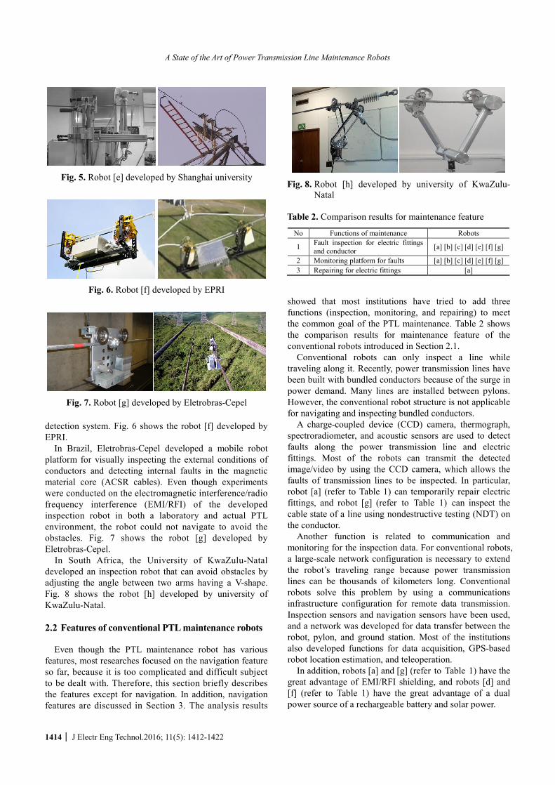
Shanghai university developed an inspection robot similar to CAS’s one that autonomously avoids obstacles on a 110kV PTL with an obstacle avoidance planning method. In particular, the robot focused on supporting navigation along an inclined line with unstable counter-balancing. Fig. 5 shows the robot [e] developed by Shanghai university.
Electric power research institute (EPRI) developed the inspection robot, “TI” in 2008. “TI” was evaluated in a field test under an EHV line environment. The results were used to develop the bypassing system, solar panels, sensor package, and power requirements. Research on its application to an actual 765kV PTL is actively being carried out through the development of autonomous navigation, a control method, and the architecture for a
Table 1. Main research institutions that have developed PTL maintenance robots
Robots Institutions References [a] Hydro-Québec (Canada) [3-11] [b] HiBot (Japan) [12-15] [c] CAS (China) [16-25] [d] Wuhan university (China) [26-32] [e] Shanghai university (China) [33-37] [f] EPRI (USA) [38-40] [g] Eletrobras-Cepel (Brazil) [41-42]
[h] University of KwaZulu-Natal (South Africa) [43-44]
Fig. 1. Robot [a] developed by Hydro-Québec
Fig. 2. Robot [b] developed by HiBot
Fig. 3. Robots [c] developed by CAS
Fig. 4. Robots [d] developed by Wuhan university
A State of the Art of Power Transmission Line Maintenance Robots
1414 │ J Electr Eng Technol.2016; 11(5): 1412-1422
detection system. Fig. 6 shows the robot [f] developed by EPRI.
In Brazil, Eletrobras-Cepel developed a mobile robot platform for visually inspecting the external conditions of conductors and detecting internal faults in the magnetic material core (ACSR cables). Even though experiments were conducted on the electromagnetic interference/radio frequency interference (EMI/RFI) of the developed inspection robot in both a laboratory and actual PTL environment, the robot could not navigate to avoid the obstacles. Fig. 7 shows the robot [g] developed by Eletrobras-Cepel.
In South Africa, the University of KwaZulu-Natal developed an inspection robot that can avoid obstacles by adjusting the angle between two arms having a V-shape. Fig. 8 shows the robot [h] developed by university of KwaZulu-Natal.
2.2 Features of conventional PTL maintenance robots
Even though the PTL maintenance robot has various
features, most researches focused on the navigation feature so far, because it is too complicated and difficult subject to be dealt with. Therefore, this section briefly describes the features except for navigation. In addition, navigation features are discussed in Section 3. The analysis results
showed that most institutions have tried to add three functions (inspection, monitoring, and repairing) to meet the common goal of the PTL maintenance. Table 2 shows the comparison results for maintenance feature of the conventional robots introduced in Section 2.1.
Conventional robots can only inspect a line while traveling along it. Recently, power transmission lines have been built with bundled conductors because of the surge in power demand. Many lines are installed between pylons. However, the conventional robot structure is not applicable for navigating and inspecting bundled conductors.
A charge-coupled device (CCD) camera, thermograph, spectroradiometer, and acoustic sensors are used to detect faults along the power transmission line and electric fittings. Most of the robots can transmit the detected image/video by using the CCD camera, which allows the faults of transmission lines to be inspected. In particular, robot [a] (refer to Table 1) can temporarily repair electric fittings, and robot [g] (refer to Table 1) can inspect the cable state of a line using nondestructive testing (NDT) on the conductor.
Another function is related to communication and monitoring for the inspection data. For conventional robots, a large-scale network configuration is necessary to extend the robot’s traveling range because power transmission lines can be thousands of kilometers long. Conventional robots solve this problem by using a communications infrastructure configuration for remote data transmission. Inspection sensors and navigation sensors have been used, and a network was developed for data transfer between the robot, pylon, and ground station. Most of the institutions also developed functions for data acquisition, GPS-based robot location estimation, and teleoperation.
In addition, robots [a] and [g] (refer to Table 1) have the great advantage of EMI/RFI shielding, and robots [d] and [f] (refer to Table 1) have the great advantage of a dual power source of a rechargeable battery and solar power.
Fig. 5. Robot [e] developed by Shanghai university
Fig. 6. Robot [f] developed by EPRI
Fig. 7. Robot [g] developed by Eletrobras-Cepel
Fig. 8. Robot [h] developed by university of KwaZulu-
Natal
Table 2. Comparison results for maintenance feature
No Functions of maintenance Robots
1 Fault inspection for electric fittings and conductor [a] [b] [c] [d] [e] [f] [g]
2 Monitoring platform for faults [a] [b] [c] [d] [e] [f] [g] 3 Repairing for electric fittings [a]

Kwang-Ho Seok and Yoon Sang Kim
http://www.jeet.or.kr │ 1415
3. Analysis of Navigation Features for PTL Maintenance Robots
3.1 Function analysis and problem deduction for
PTL navigation The analysis showed that most of the robots developed
by the eight research institutions have their own navigation mechanism for transmission lines. Reliable line gripping and high-speed traveling are advantageous because each robot navigates with a line groove between the wheels. Except for robot [b] (refer to Table 1), most of the robots navigate along a single line using wheels that are linked to the rear and front arms: that is, robot [b] can navigate a two-conductor bundle using four wheels that are linked to two pairs of rear arms and front arms. Functions were developed to avoid obstacles located on a PTL, such as spacer dampers, clamps, and electric fittings. The inspection robots avoid obstacles by rotational / perpendicular motion of the arms. Except for robot [g] (refer to Table 1), most of the robots can avoid obstacles by moving the robot arm that is directly linked to the wheel. Robot [a] (refer to Table 1) uses an additional arm equipped with a gripper. This obstacle avoidance function can also be used in navigation for pylon bypassing. Most of the robots can avoid the suspension and strain insulator in the same manner as they avoid electric fittings. The analysis results showed that the most important function is automatic navigation on a transmission line. To achieve this goal, the inspection robot should first be able to dock on the line by climbing a pylon autonomously. However, most institutions place the robots on the line by using a crane and human operator. Pylon bypass is also the main feature of the PTL maintenance robot. Navigation is easy because the insulator of suspension tower (A-type towers) is not located on the traveling path of the robot, whereas navigation is difficult because the insulator is placed on the traveling path of the robot in the strain tower (B-type towers, C-type tower). Conventional robots bypass the pylon via the jumper line navigation to avoid strain insulator. However, various jumper line types and structures were difficult for stable navigation.
3.2 Main feature derivation for PTL navigation
In this subsection, the problems discussed in Section 3.1
are used to derive and classify the main features of transmission line maintenance robots by analyzing the navigation function of conventional robots. Navigation feature of PTL maintenance robot is affected by the line/tower configurations such as type of tower, insulator configuration, and type/number of electric fittings. Six main features are derived from the correlation analysis of the tower configurations and functions for PTL navigation. Table 3 shows the derived results (six main features) for PTL navigation. Feature A includes functions for a live line-climbing mechanism. Feature B includes functions for
traveling along bundled conductors. Feature C includes functions for an obstacle avoidance mechanism. Feature D includes functions for a strain pylon bypassing mechanism. Feature E includes functions for a suspension pylon bypassing mechanism. Feature F includes functions for pylon access and line gripping mechanism.
4. Quantitative and Qualitative Assessment Using Statistical Analysis
4.1 Readiness level assessment
In this section, readiness level assessment of the
conventional robots is performed based on the main features derived in previous section. Technology readiness level (TRL) [45] defined by NASA is used for quantitative and qualitative assessment of conventional robots. TRL is a systematic approach that evaluates the readiness level of a particular technology and compares the one between different types of technology. Table 4 shows the technology readiness levels. TRL is defined as a total of 9 levels from basic phase to the commercialization one, and we are given a score divided into 5 steps for derived main feature analysis.
In addition, integration readiness level (IRL) [46] is used for compatible interactions of various technologies and
Table 4. Technology readiness levels Level Phase Definition Score
1 Basic principles observed and reported
2
Basic Technology
Research Technology concept and/or application
formulated
1 (0.2)
3 Analytical and experimental critical
function and/or characteristic proof of concept
4
Technology Development Component and/or breadboard
validation in laboratory environment
2 (0.4)
5 Component and/or breadboard validation in relevant environment
6
Technology Demonstration System/subsystem model or prototype
demonstration in a relevant environment (ground or space)
3 (0.6)
7 System prototype demonstration in a space environment
8
System Development Actual system completed and “flight
qualified” through test and demonstration (ground or space)
4 (0.8)
9 System Test, Launch, and Operations
Actual system “flight proven” through successful mission operations
5 (1.0)
Table 3. Six features for PTL navigation
Main features A Live line navigation B Bundled conductors navigation
C Obstacle(clamps, spacer, vibration damper) avoidance navigation
D Strain pylon bypassing navigation E suspension pylon bypassing navigation F Pylon/line docking navigation

A State of the Art of Power Transmission Line Maintenance Robots
1416 │ J Electr Eng Technol.2016; 11(5): 1412-1422
consistent comparison of the readiness level between integration points. IRL was developed for the accurate evaluation to see how the integration between technologies effects overall system development. Table 5 presents the integration readiness levels. IRL is defined as a total of 9 levels, and we are given a score divided into 5 steps for derived main feature analysis.
In conclusion, system readiness level (SRL) was used to evaluate the readiness level of overall system, the SRL estimates the complexity of each technology, corresponding integrations, and compatibility using the functional relations between TRL and IRL, and it assesses the readiness levels of potential system quantitatively.
For a system with n technologies (features), TRL is given by
1
2
n
TRLTRL
TRL
TRL
é ùê úê ú=ê úê úë û
M (1)
where, 1TRL = Feature A, 2TRL = Feature B, 3TRL = Feature C, 4TRL = Feature D, 5TRL = Feature E, 6TRL = Feature F
temp ij iSRL IRL TRL= ´
11 1 12 2 1
21 1 22 2 2
1 1 2 2
n n
n n
n n nn n
IRL TRL IRL TRL IRL TRLIRL TRL IRL TRL IRL TRL
IRL TRL IRL TRL IRL TRL
+ + +é ùê ú+ + +ê ú=ê úê ú
+ + +ê úë û
LL
ML
(2)
Table 6. Systems readiness levels
Phase SRL range Definition Readiness level 5 0.9-1.0 Operations & Support 4 0.7-0.89 Production High
3 0.6-0.69 System Development & Demonstration
2 0.4-0.59 Technology Development Medium
1 0.1-0.39 Concept Refinement Low Table 7. TRL analysis results for PTL maintenance robots
TRL1 TRL2 TRL3 TRL4 TRL5 TRL6 Features Robots A B C D E F
[a] 1.0 0.8 1.0 0.4 1.0 0.2 [b] 1.0 1.0 1.0 0.4 1.0 0.2 [c] 1.0 0.4 1.0 0.8 1.0 0.2 [d] 1.0 0.4 1.0 0.8 1.0 0.2 [e] 1.0 0.4 0.8 0.6 1.0 0.2 [f] 1.0 0.4 0.8 0.6 0.6 0.2 [g] 1.0 0.4 0.4 0.4 0.4 0.2 [h] 0.8 0.4 0.8 0.8 0.8 0.2
where, ij jiIRL IRL=
/i temp iSRL SRL n= (3)
where, 1SRL = Feature A, 2SRL = Feature B, 3SRL = Feature C, 4SRL = Feature D, 5SRL = Feature E, 6SRL = Feature F
The representation of each of the SRLtemp values obtained in (2) addresses the relations of TRLs and IRLs. Each value is TRL score of Table 4 and IRL score of Table 5. When no integration is present between two technologies, the IRL value should be assigned as 0. Its corresponding SRLi in (3) is divided by ni to obtain its normalized value between (0, 1). In addition, the SRL for the complete system is the average of all such normalized technologies’ SRL values. The SRL range is from 0.0 to 1.0, and readiness level for analysis is assigned with a three values: high, medium, and low. Table 6 presents the system readiness level.
SRL was obtained based on the six main features of Table 3 to analyze the navigation of conventional robot. The navigation features were evaluated by six scales: 5 (commercialization), 4 (real field test-phase), 3 (prototype test-phase), 2 (development-phase), 1 (research-phase), and 0 (none). Table 7 shows the TRL analysis results for PTL maintenance robots. The maximum and minimum scores of each feature were 1 and 0, respectively.
Table 8 presents the ni values for SRL results derivation. ni in (3) means the number of integrations of technology i (feature A-F) with itself and every other technology. In addition, Table 9 lists IRL analysis results for PTL maintenance robots.
Table 10 presents the analysis results for SRL of PTL maintenance robots. Table 10 lists the major research institutions defined by Table 1, and six features (A-F) are 6 main features of the navigation defined as Table 3. Fig. 9
Table 5. Integration readiness levels
Level Definition Score
1 An Interface between technologies has been identified with sufficient detail to allow charac-terization of the relationship
2 There is some level of specificity to characterize the Interaction (i.e. ability to influence) between technologies through their interface
1 (0.2)
3 There is Compatibility (i.e. common language) between technologies to orderly and efficiently integrate and interact
4 There is sufficient detail in the Quality and Assurance of the integration between technologies
2 (0.4)
5 There is sufficient Control between technologies necessary to establish, manage, and terminate the integration
6 The integrating technologies can accept, Translate, and Structure Information for its intended application
3 (0.6)
7 The integration of technologies has been Verified and Validated with sufficient detail to be actionable
8 Actual integration completed and Mission Qualified through test and demonstration, in the system environment
4 (0.8)
9 Integration is Mission Proven through successful mission operations
5 (1.0)

Kwang-Ho Seok and Yoon Sang Kim
http://www.jeet.or.kr │ 1417
shows the SRL result of robots analyzed using a radar chart. The scores of robot [a] for features A, B, C, D, E, and F were 0.79, 0.52, 0.73, 0.36, 0.87, and 0.04, respectively. However, the score for feature A showed that robot [a] has difficulty with traveling on bundled conductors and climbing autonomously without the help of an operator. In addition, navigation to avoid the strain-type insulators was difficult due to heavy weight (100kg). The scores of robot
[b] for features A, B, C, D, E, and F were 0.79, 0.72, 0.82, 0.24, 0.95, and 0.04, respectively. Robot [b] provides reliable traveling movement because it has a structure capable of gripping bundled conductors, but it finds bypassing the pylon very difficult. The scores of robot [c] for features A, B, C, D, E, and F were 0.82, 0.32, 0.65, 0.50, 0.74, and 0.04, respectively. Robot [c] could avoid obstacles by motion of the two arms. It can bypass pylons consisting of strain-type insulator with a jumper-line, but it has difficulty with traveling overall because of the strong influence of the jumper-line structure. The scores of robot [d] for features A, B, C, D, E, and F were 0.86, 0.32, 0.68, 0.60, 0.74, and 0.04, respectively. Robot [d] has similar characteristics to robot [c]. However, it has a different approach to avoiding obstacles with a new snake-type mechanism. The new snake-type robot has a large advantage when traveling between pylons and avoiding obstacles.
The scores of robot [e] for features A, B, C, D, E, and F were 0.63, 0.28, 0.51, 0.35, 0.65, and 0.04, respectively. Robot [e] has a very similar mechanism to robot [c]. The scores of robot [f] for features A, B, C, D, E, and F were 0.49, 0.24, 0.34, 0.31, 0.31, and 0.04, respectively. The structure of robot [f] cannot be applied directly to the existing PTL environment. It has the advantage of sensing technology but finds it very difficult to bypass pylons and avoid obstacles. To travel on existing PTLs, the robot needs new lines to be installed. The scores of robot [g] for
Fig. 9. Analysis result for robots
Table 8. ni values for SRL results derivation n1 n 2 n 3 n 4 n 5 n 6 Features
Robots A B C D E F [a] 4 4 5 4 4 1 [b] 4 4 5 4 4 1 [c] 4 4 5 4 4 1 [d] 4 4 5 4 4 1 [e] 4 4 5 4 4 1 [f] 4 4 5 4 4 1 [g] 4 4 5 4 4 1 [h] 4 4 5 4 4 1
Table 9. IRL analysis results for PTL maintenance robots
Robot [a] Robot [b] Robot [c] Robot [d] IRLij A B C D E F A B C D E F A B C D E F A B C D E F A 1.0 0.0 1.0 0.4 1.0 0.0 1.0 0.0 1.0 0.4 1.0 0.0 1.0 0.0 0.8 0.6 1.0 0.0 1.0 0.0 0.8 0.8 1.0 0.0 B 0.0 0.8 0.6 0.6 0.6 0.0 0.0 1.0 1.0 0.2 0.8 0.0 0.0 0.4 0.4 0.4 0.4 0.0 0.0 0.4 0.4 0.4 0.4 0.0 C 1.0 0.6 1.0 0.4 1.0 0.0 1.0 1.0 1.0 0.2 1.0 0.0 0.8 0.4 1.0 0.6 0.8 0.0 0.8 0.4 1.0 0.8 0.8 0.0 D 0.4 0.6 0.4 0.4 0.0 0.0 0.4 0.2 0.2 0.4 0.0 0.0 0.6 0.4 0.6 0.8 0.0 0.0 0.8 0.4 0.8 0.8 0.0 0.0 E 1.0 0.6 1.0 0.0 1.0 0.0 1.0 0.8 1.0 0.0 1.0 0.0 1.0 0.4 0.8 0.0 1.0 0.0 1.0 0.4 0.8 0.0 1.0 0.0 F 0.0 0.0 0.0 0.0 0.0 0.2 0.0 0.0 0.0 0.0 0.0 0.2 0.0 0.0 0.0 0.0 0.0 0.2 0.0 0.0 0.0 0.0 0.0 0.2
Robot [e] Robot [f] Robot [g] Robot [h] IRLij A B C D E F A B C D E F A B C D E F A B C D E F A 1.0 0.0 0.6 0.4 0.8 0.0 1.0 0.0 0.6 0.4 0.4 0.0 1.0 0.0 0.4 0.4 0.4 0.0 0.8 0.0 0.6 0.6 0.6 0.0 B 0.0 0.4 0.4 0.4 0.4 0.0 0.0 0.4 0.4 0.4 0.4 0.0 0.0 0.4 0.4 0.4 0.4 0.0 0.0 0.4 0.4 0.4 0.4 0.0 C 0.6 0.4 0.8 0.6 0.8 0.0 0.6 0.4 0.6 0.4 0.4 0.0 0.4 0.4 0.4 0.4 0.4 0.0 0.6 0.4 0.8 0.6 0.6 0.0 D 0.4 0.4 0.6 0.6 0.0 0.0 0.4 0.4 0.6 0.0 0.0 0.0 0.4 0.4 0.4 0.4 0.0 0.0 0.6 0.4 0.6 0.8 0.0 0.0 E 0.8 0.4 0.8 0.0 1.0 0.0 0.4 0.4 0.4 0.0 0.6 0.0 0.4 0.4 0.4 0.0 0.4 0.0 0.6 0.4 0.6 0.0 0.8 0.0 F 0.0 0.0 0.0 0.0 0.0 0.2 0.0 0.0 0.0 0.0 0.0 0.2 0.0 0.0 0.0 0.0 0.0 0.2 0.0 0.0 0.0 0.0 0.0 0.2
Table 10. SRL analysis results for PTL maintenance robots SRL1 SRL2 SRL3 SRL4 SRL5 SRL6 Features
Robots A B C D E F [a] 0.79 0.52 0.73 0.36 0.87 0.04 [b] 0.79 0.72 0.82 0.24 0.95 0.04 [c] 0.82 0.32 0.65 0.50 0.74 0.04 [d] 0.86 0.32 0.68 0.60 0.74 0.04 [e] 0.63 0.28 0.51 0.35 0.65 0.04 [f] 0.49 0.24 0.34 0.31 0.31 0.04 [g] 0.37 0.16 0.21 0.22 0.22 0.04 [h] 0.52 0.28 0.45 0.44 0.44 0.04

A State of the Art of Power Transmission Line Maintenance Robots
1418 │ J Electr Eng Technol.2016; 11(5): 1412-1422
features A, B, C, D, E, and F were 0.37, 0.16, 0.21, 0.22, 0.22, and 0.04, respectively. Robot [g] has a very simple mechanism and has difficulty with obstacle avoidance. The scores of robot [h] for features A, B, C, D, E, and F were 0.52, 0.28, 0.45, 0.44, 0.44, and 0.04, respectively. Robot [h] has a very simple mechanism but can avoid obstacles and bypass pylons through jumper-line traveling. However, it has difficulties with avoiding long obstacles. From the analysis result, most robots were impossible to grip the line to climb the tower autonomously without the operator.
4.2 Navigation features analysis
In this section, navigation features are analyzed using
the statistical approach. The navigation analysis confirmed that most robots use similar mechanisms for navigation. Most of the navigation mechanisms enable robots to avoid obstacles by adjusting the length of the arm and bypass pylons by jumper-line traveling. Counterbalancing control was found to have the most important role for navigation. Fully autonomous navigation is impossible because most robots are placed on the line by a vehicle (e.g., crane or truck) and human resources. Table 11 shows the analysis results for the six main features. Out of 1.0 total score of each main feature, the scores for features A, B, C, D, E, and F were 0.66, 0.36, 0.55, 0.38, 0.62, and 0.04, respectively. The readiness levels were divided into low
(0.00-0.39), medium (0.40-0.69), and high (0.70-1.00) depending on the scores of each main feature. Features A, C, and E showed medium readiness level. More development is needed for commercialization. Features B, D, and E showed low readiness level. More research is needed for development.
Table 12 presents the factors of features A, B, C, D, E, and F obtained using the statistical analysis. The following factors were used for the statistical analysis: first quartile (Q1), min, median, max, third quartile (Q3), mean, standard deviation (SD), standard error of the mean (SE), and confidence interval (CI). Those factors can measure from the SRL analysis results of Table 10.
Fig. 10 shows the statistical analysis results including max, min, median, interquartile range, mean, and confidence interval (CI) of features A, B, C, and D using box and whisker plot. The low and high of the box (interquartile range) represents the data from the first quartile (25% position) and the third quartile (75% position), respectively. Feature A (red), C (blue), and E (pink) showed that the interquartile range was similar, and feature B (green), D (yellow), and F (brown) were lower than others. In particular, feature F (brown) was the lowest. The outliers
Table 11. Analysis results for main features Main features Score (1.0) Readiness level
Feature A Feature B Feature C Feature D Feature E Feature F
0.66 0.36 0.55 0.38 0.62 0.04
Medium Low
Medium Low
Medium Low
Fig. 10. Statistical analysis results using box and whisker plot
Table 12. Factors of features A, B, C, D, E, and F for the statistical analysis
Factors A B C D E F N
Q1 Min
Median Max Q3
Mean SD SE CI
8 0.51 0.37 0.71 0.86 0.80 0.66 0.18 0.06 0.15
8 0.27 0.16 0.30 0.72 0.37 0.36 0.18 0.06 0.15
8 0.42 0.21 0.58 0.82 0.69 0.55 0.21 0.07 0.17
8 0.29 0.22 0.36 0.60 0.46 0.38 0.13 0.05 0.11
8 0.41 0.22 0.70 0.95 0.77 0.62 0.26 0.09 0.22
8 0.04 0.04 0.04 0.04 0.04 0.04 0.00 0.00 0.00

Kwang-Ho Seok and Yoon Sang Kim
http://www.jeet.or.kr │ 1419
were represented by an dot (•). The readiness level for each feature was examined
through whiskers analysis showing confidence interval. Features A, C, and E showed medium-readiness level, and features B, D, and F showed low-readiness level. Those are navigation features for traveling along bundled conductors, a strain pylon bypassing mechanism, and pylon access and line gripping mechanism, and we confirmed that more research and development are required. The ultimate goal for a PTL maintenance robot is to develop its functions to completely take over the role of a worker. However, until now most institutions have not invested a great deal of research in the early stages of development from the results.
5. Conclusion
In this paper, we reviewed state-of-the-art PTL
maintenance robots developed by eight major research institutions, and derived main features for navigation. By analyzing the correlations of the tower configurations and functions for PTL navigation, the six main features derived are navigation for live line (feature A), navigation for bundled conductors (feature B), navigation for obstacle avoidance (feature C), navigation for strain pylon bypassing (feature D), navigation for suspension pylon bypassing (feature E), and navigation for pylon/line docking (feature F). Those main features were analyzed quantitatively and qualitatively through readiness level assessment. For this, SRL was used to evaluate the readiness level of overall system, and obtained by using TRL and IRL. In addition, the readiness level for each feature was reviewed through statistical analysis using box and whisker plot. The readiness levels were divided into three ones; low (0.00-0.39), medium (0.40-0.69), and high (0.70-1.00) depending on the scores of each main feature. The mean score for feature A was 0.66 out of 1.0 which can be considered as the medium readiness level. From the analysis result, it was shown that feature A was the most basic navigation research topic in the most institutions. The navigation analysis confirmed that most robots used similar mechanisms for navigation. The mean score for feature B was 0.36 out of 1.0 which can be inferred as the low readiness level. From the analysis result, it was conformed that most robot navigations were suitable for single line. The mean score for feature C was 0.55 out of 1.0 which can be considered as the medium readiness level. From the analysis result, it was found that obstacle avoidance was one of the priority features, and most institutions have actively performed research and development. The mean score for feature D was 0.38 out of 1.0 which can be inferred as the low readiness level. From the analysis result, it was shown that navigation was unstable but robot was able to bypass the pylon via the jumper line. The mean score for feature E was 0.62 out of 1.0 which can be considered as the medium readiness level. From the analysis result, it was found that robots bypassed the pylon in similar way of feature C. The
mean score for feature F was 0.04 out of 1.0 which can be inferred as the low readiness level. From the analysis result, it was conformed that feature F was not dealing with the navigation research in the most institutions. In addition, the distribution ratio of for features A, B, C, D, E, and F were 25%, 14%, 21%, 15%, 24%, and 1%, respectively. Those distribution results show the ratio of the six main features. Feature A, B, C, D, and E was showing that a similar distribution, but feature E were showing that a low ratio. From our study, we could find out that research on navigation for live line, navigation for bundled conductors, navigation for obstacle avoidance, navigation for strain pylon bypassing, and navigation for suspension pylon bypassing was actively being carried out, whereas most robots were unable to grip the line to climb the tower autonomously. We could reach such a conclusion that more technology development for bundled conductors navigation, strain pylon bypassing navigation, and pylon/line docking navigation is required. In particular, if the robot is docked on the line with the help of the equipment such crane or helicopter, it could raise questions about the use of a PTL maintenance robot. In conclusion, the importance of the needs for technical development and research, for the navigation as well as for pylon/line docking (feature F) was confirmed.
References
[1] Shin-ichi Aoshima, Takeshi Tsujimura and Tetsuro Yabuta, “A Wire Mobile Robot with Multi-unit Structure,” in Proceedings of the IEEE/RSJ Inter-national Workshop on Intelligent Robots and Systems, pp. 414-421, 1989.
[2] Jun Sawada, Kazuyuki Kusumoto, Tadashi Munakata, Yasuhisa Maikawa and Yoshinobu Ishikawa, “A Mobile Robot for Inspection of Power Transmission Lines,” IEEE Transactions on Power Delivery, vol.6, no.1, pp. 309-315, 1991.
[3] Serge Montambault and Nicolas Pouliot, “The HQ LineROVer: Contributing to Innovation in Trans-mission Line Maintenance,” in Proceedings of the IEEE 10th International Conference on Transmission and Distribution Construction, Operation and Live-Line Maintenance, pp. 33-40, 2003.
[4] Serge Montambault and Nicolas Pouliot, “LineScout Technology: Development of an Inspection Robot Capable of Clearing Obstacles While Operating on a Live Line,” in Proceedings of the IEEE 11th Inter-national Conference on Transmission and Distribution Construction, Operation and Live-Line Maintenance, 2006.
[5] Nicolas Pouliot and Serge Montambault, “Geometric Design of the LineScout, a Teleoperated Robot for Power Line Inspection and Maintenance,” in Pro-ceedings of the IEEE International Conference on

A State of the Art of Power Transmission Line Maintenance Robots
1420 │ J Electr Eng Technol.2016; 11(5): 1412-1422
Robotics and Automation, pp. 3970-3977, 2008. [6] Serge Montambault and Nicolas Pouliot, “Design and
Validation of a Mobile Robot for Power Line Inspection and Maintenance,” Field and Service Robotics, vol. 42, pp. 495-504, 2008.
[7] Nicolas Pouliot and Serge Montambault, “LineScout Technology: From Inspection to Robotic Maintenance on Live Transmission Power Lines,” in Proceedings of the IEEE International Conference on Robotics and Automation, pp. 1034-1040, 2009.
[8] Nicolas Pouliot, Pierre Latulippe and Serge Montam-bault, “Reliable and Intuitive Teleoperation of Line-Scout: a Mobile Robot for Live Transmission Line Maintenance,” in Proceedings of the IEEE/RSJ International Conference on Intelligent Robots and Systems, pp.1703-1710, 2009.
[9] Janos Toth, Nicolas Pouliot and Serge Montambault, “Field Experiences Using LineScout Technology on Large BC Transmission Crossings,” in Proceedings of the 1st International Conference on Applied Robotics for the Power Industry, 2010.
[10] Pierre-Luc Richard, Nicolas Pouliot and Serge Montambault, “Introduction of a LIDAR-Based Obstacle Detection System on the LineScout Power Line Robot,” in Proceedings of the IEEE/ASME International Conference on Advanced Intelligent Mechatronics (AIM), pp.1734-1740, 2014.
[11] Nicolas Pouliot, Pierre-Luc Richard and Serge Montambault, “LineScout Technology Opens the Way to Robotic Inspection and Maintenance of High-Voltage Power Lines,” IEEE Power and Energy Technology Systems Journal, vol. 2, no. 1, 2015.
[12] Paulo Debenest, Michele Guarnieri, Kensuke Takita, Edwardo F. Fukushima, Shigeo Hirose, Kiyoshi Tamura, Akihiro Kimura, Hiroshi Kubokawa, Narumi Iwama and Fuminori Shiga, “Sensor-Arm-Robotic Manipulator for Preventive Maintenance and Inspec-tion of High-Voltage Transmission Lines,” in Proceedings of the IEEE / RSJ International Con-ference on Intelligent Robots and Systems, pp.1737-1744, 2008.
[13] Paulo Debenest, Michele Guarnieri, Kensuke Takita, Edwardo F. Fukushima, Shigeo Hirose, Kiyoshi Tamura, Akihiro Kimura, Hiroshi Kubokawa, Narumi Iwama and Fuminori Shiga, “Expliner - Robot for Inspection of Transmission Lines,” in Proceedings of the IEEE International Conference on Robotics and Automation, pp.3978-3984, 2008.
[14] Paulo Debenest and Michele Guarnieri, “Expliner - From Prototype Towards Practical Robot for Inspection of High-Voltage Lines,” in Proceedings of the International Conference on Applied Robotics for the Power Industry, 2010.
[15] Paulo Debenest, Michele Guarnieri, Kensuke Takita, Edwardo F. Fukushima, Shigeo Hirose, Kiyoshi
Tamura, Akihiro Kimura, Hiroshi Kubokawa, Narumi Iwama, Fuminori Shiga, Yukio Morimura and Youichi Ichioka, “Expliner-Toward a Practical Robot for Inspection of High-Voltage Lines,” Field and Service Robotics, vol. 62, pp. 45-55, 2010.
[16] Tang Li, Fang Lijin and Wang Hongguang, “Development of An Inspection Robot Control System for 500kV Extra-High Voltage Power Trans-mission Lines,” in Proceedings of the SICE Annual Conference, pp.1819-1824, 2004.
[17] Wang Ludan, Fang Lijin, Wang Hongguang and Zhao Mingyang, “Development and Control of an Autonomously Obstacle-Navigation Inspection Robot for Extra-High Voltage Power Transmission Lines,” in Proceedings of the SICE-ICASE International Joint Conference, pp.5400-5405, 2006.
[18] Wang Ludan, Wang Hongguang and Fang Lijin, “Obstacle-Navigation Control of Power Transmission Lines Inspection Robot,” in Proceedings of the IEEE International Conference on Robotics and Biomi-metics, pp.706-711, 2007.
[19] Wang Hongguang, Jiang Yong, Liu Aihua, Fang Lijin and Ling Lie, “Research of Power Transmission Line Maintenance Robots in SIACAS,” in Proceedings of the 1st International Conference on Applied Robotics for the Power Industry, 2010.
[20] Song Yifeng, Wang Hongguang and Ling Lie, “Research on the Influence of the Driving Wheel and Robot Posture on Climbing Capability of a Trans-mission Line Inspection Robot,” in Proceedings of the IEEE 6th Conference on Industrial Electronics and Applications, pp.1632-1639, 2011.
[21] Song Yifeng, Wang Hongguang, Jiang Yong and Ling Lie, “AApe-D: a Novel Power Transmission Line Maintenance Robot for Broken Strand Repair,” in Proceedings of the 2nd International Conference on Applied Robotics for the Power Industry, pp.108-113, 2012.
[22] Si-Yao Fu, Yun-Chu Zhang, Long Cheng, Zi-Ze Liang, Zeng-Guang Hou and Min Tan, “Motion Based Image Deblur Using Recurrent Neural Network for Power Transmission Line Inspection Robot,” in Proceedings of the International Joint Conference on Neural Networks, pp. 3854-3859, 2006.
[23] Si-Yao Fu, Zi-Ze Liang, Zeng-Guang Hou and Min Tan, “Vision based Navigation for Power Trans-mission Line Inspection Robot,” in Proceedings of the IEEE 7th International Conference on Cognitive Informatics, pp. 411-417, 2008.
[24] Guodong Yang, En Li, Changchun Fan, Weiyang Lei and Zi-Ze Liang, “Modeling and Control of a Bi-brachiate Inspection Robot for Power Transmission Lines,” in Proceedings of the IEEE International Conference on Mechatronics and Automation, pp. 1036-1041, 2010.
[25] Song Yifeng, Wang Lin, Jiang Yong, Wang Hongguang,

Kwang-Ho Seok and Yoon Sang Kim
http://www.jeet.or.kr │ 1421
Jiang Wendong, Wang Cancan, Chu Jinliang and Han Dongfeng, “A Vision-based method for the Broken Spacer Detection,” in Proceedings of the 5th Annual IEEE International Conference on Cyber Technology in Automation, Control and Intelligent Systems, pp. 715-719, 2015.
[26] Gongping Wu, Xiaohui Xiao, E Du and Sanping Li, “Kinematics and Dynamics Simulation of Inspection Robot for Power Transmission Line,” in Proceedings of the 5th WSEAS International Conference on Signal Processing, Robotics and Automation, pp. 70-76, 2006.
[27] Gongping Wu, Xiaohui Xiao and Yuanbiao Lai, “A Wheel-Claw Hybrid Manipulator and its Grasping Stability for the Mobile Robot Rolling/Crawling along Flexible Cable,” in Proceedings of the International Workshop on Robotic and Sensors Environments, 2007.
[28] Gongping Wu, Tuo Zheng, Hua Xiao and Cheng Li, “Navigation, Location and Non-collision Obstacles Overcoming for High-Voltage Power Transmission-Line Inspection Robot,” in Proceedings of the International Conference on Mechatronics and Automation, pp.2014-2020, 2009.
[29] Gongping Wu, Heng Cao, Xianjin Xu, Hua Xiao, Shengbang Li, Qingshan Xu, Bin Liu, Qinghong Wang, Zhijun Wang and Yulin Ma, “Design and Application of Inspection System in a Self-Governing Mobile Robot System for High Voltage Transmission Line Inspection,” in Proceedings of the Asia-Pacific Power and Energy Engineering Conference, 2009.
[30] Gongping Wu, Hua Xiao, Xiaohui Xiao, Zhenglie Huang and Yingsong Li, “Transmission Line Inspec-tion Robot and Deicing Robot: Key Technologies, Prototypes and Applications,” in Proceedings of the 1st International Conference on Applied Robotics for the Power Industry, 2010.
[31] Wei Wang, Yucheng Bai, Gongping Wu, Shuixia Li and Qian Chen, “The Mechanism of a Snake-Like Robot’s Clamping Obstacle Navigation on High Voltage Transmission Lines,” International Journal of Advanced Robotic Systems, vol. 10, pp. 1-14, 2013.
[32] Wei Xing-wei Fu, Gongping Wu, Peng Zhou and Na Yu, “Energy-consumption estimation of inspection robot based on Kalman filter,” Journal of Zhejiang University(Engineering Science), 2015.
[33] Zhibin Ren and Yi Ruan, “Planning and Control in Inspection Robot for Power Transmission Lines,” in Proceedings of the IEEE International Conference on Industrial Technology, 2008.
[34] Zheng Li, Yi Ruan and Feng Zhang, “A New Posture Plan for the Inspection Robot Capable of Clearing Obstacles in Power Transmission Line Maintenance,” in Proceedings of the Asia-Pacific Power and Energy Engineering Conference, 2009.
[35] Jian Jin, Guoxian Zhang and Tingyu Zhang, “Design of a Mobile Robot for the Innovation in Power Line Inspection and Maintenance,” in Proceedings of the ASME/IFToMM International Conference on Re-configurable Mechanisms and Robots, pp. 444-449, 2009.
[36] Jian Jin, Huajin Zhu and Guoxian Zhang, “Counter-weight-Navigation of a Mobile Inspection Robot Working on the Ground Wires,” in Proceedings of the IEEE International Conference on Automation and Logistics, pp. 278-282, 2009.
[37] Zheng Li and Yi Ruan, “Autonomous Inspection Robot for Power Transmission Lines Maintenance While Operating on the Overhead Ground Wires,” International Journal of Advanced Robotic Systems, vol. 7, no. 4, pp.111-116, 2010.
[38] Andrew Phillips, “Robotic Inspection of Trans-mission Lines,” EPRI, 2010.
[39] Don Kintner, “ “Ti” EPRI Transmission Line Robot Development - Executive Summary,” EPRI, 2012.
[40] Andrew Phillips, Eric Engdahl, Drew McGuire, Mark Major and Glynn Bartlett, “Autonomous Overhead Transmission Line Inspection Robot (TI) Development and Demonstration,” in Proceedings of the 2nd International Conference on Applied Robotics for the Power Industry, pp. 94-95, 2012.
[41] Ary Vaz Pinto, Mauro Zanini Sebrao, Celia Regina S. H. Lourenco, Ildejairo Sant’Anna de Almeida, Joao Saad Jr and Plutarcho M. Lourenco, “Remote Detection of Internal Corrosion in Conductor Cables of Power Transmission Lines,” in Proceedings of the 1st International Conference on Applied Robotics for the Power Industry, 2010.
[42] Alisson Fonseca, Ricardo Abdo and João Alberto, “Robot for Inspection of Transmission Lines,” in Proceedings of the 2nd International Conference on Applied Robotics for the Power Industry, pp. 83-87, 2012.
[43] Trevor Lorimer and Ed Boje, “A Simple Robot Manipulator Able to Negotiate Power Line Hard-ware,” in Proceedings of the 2nd International Conference on Applied Robotics for the Power Industry, pp.120-125, 2012.
[44] Timothy Rowell and Ed Boje, “Obstacle Avoidance for a Power Line Inspection Robot,” in Proceedings of the 2nd International Conference on Applied Robotics for the Power Industry, pp.114-119, 2012.
[45] John C. Mankins, “Technology Readiness Levels-A White Paper,” NASA, 1995.
[46] Jose Emmanuel Ramirez-Marquez and Brian J. Sauser, “System Development Planning via System Maturity Optimization,” IEEE Transactions of Engineering Management, vol. 56, no. 3, pp. 533-548, 2009.

A State of the Art of Power Transmission Line Maintenance Robots
1422 │ J Electr Eng Technol.2016; 11(5): 1412-1422
Kwang-Ho Seok He received his B.S., M.S., and Ph.D. degrees in computer science and engineering from Korea University of Technology and Edu-cation, Cheonan, Korea in 2007, 2009, and 2015, respectively. He is currently a Post-Doctor researcher at Human-Centered Interaction Laboratory, Korea
University of Technology and Education, Cheonan, Korea. His research interests include Human-Robot Interaction, Power-IT technology, and Robotics.
Yoon Sang Kim He received the B.S., M.S., and Ph.D. degrees in electrical engineering from Sungkyunkwan Uni-versity, Seoul, Korea, in 1993, 1995, and 1999, respectively. He was a Member of the Postdoctoral Research Staff of Korea Institute of Science and Technology (KIST), Seoul, Korea. He
was also a Faculty Research Associate in the Department of Electrical Engineering, University of Washington, Seattle, USA. He was a Member of the Senior Research Staff, Samsung Advanced Institute of Technology (SAIT), Suwon, Korea. Since March 2005, he has been a Professor at the School of Computer and Science Engineering, Korea University of Technology Education (KOREATECH), Cheonan, Korea. His current research interests include Virtual simulation, Power-IT technology, and Bioengineering application. Dr. Kim was awarded Korea Science and Engineering Foundation (KOSEF) Overseas Postdoctoral Fellow in 2000. He is a member of IEEE, IEICE, ICASE, KIPS, KIEE, and KIIEE.