
A Special Content Electronic Edition of Maritime Reporter...
17
MARITIME REPORTER A Special Content Electronic Edition of Maritime Reporter & Engineering News • July/August 2018 AND ENGINEERING NEWS M A R I N E L I N K . C O M MR White Papers
Transcript of A Special Content Electronic Edition of Maritime Reporter...

MARITIMEREPORTER
A Special Content Electronic Edition of Maritime Reporter & Engineering News • July/August 2018
ANDENGINEERING NEWS
M A R I N E L I N K . C O M
MRWhite
Papers

Marine Reporter & Engineering News 1http://whitepapers.marinelink.com/
Ship Repair & Conversion
Electronic Fuel Management
10 Selecting Mechanically Attached Fittings
2 Fuel Management Systems Improve Vessel Operations through Automation
HQ118 E. 25th St., 2nd FloorNew York, NY 10010 USA
Tel +1 212 477 6700Fax +1 212 254 6271www.marinelink.com
FL Office 215 NW 3rd St
Boynton Beach, FL 33435-4009Tel +1 561 732 4368Fax +1 561 732 6984
PublishersJohn E. O’Malley John C. O’Malley
Associate Publisher/Editorial DirectorGreg Trauthwein [email protected]
Vice President, SalesRob Howard [email protected]
Web EditorEric Haun [email protected]
Web ContributorMichelle Howard [email protected]
EditorialJoseph Fonseca - India
Claudio Paschoa - BrazilPeter Pospiech - Germany
ProductionIrina Tabakina [email protected] Ventimiglia [email protected]
Corporate StaffMark O’Malley, Public RelationsEsther Rothenberger, AccountingGabby DelGatto, Office Manager
Information TechnologyVladimir Bibik
Emin Tule
SubscriptionKathleen Hickey [email protected]
Sales Lucia Annunziata [email protected] +1 212 477 6700 John Cagni [email protected]
+1 631 472 2715 Terry Breese [email protected]
+1 561 732 1185 Frank Covella [email protected]
+1 561 732 1659 Mitch Engel [email protected]
+1 561 732 0312 Mike Kozlowski [email protected] +1 561 733 2477 Jean Vertucci [email protected]
+1 212 477 6700
International Sales Scandinavia Roland Persson [email protected] Orn Marketing AB, Box 184 , S-271 24 Ystad, Sweden t: +46 411-184 00 f: +46 411 105 31
Western Europe Uwe Riemeyer [email protected] t: +49 202 27169 0 f: +49 202 27169 20
United Kingdom Paul Barrett [email protected] Hallmark House, 25 Downham Road, Ramsden Health, Essex CM11 1PU UK t: +44 1268 711560 m: +44 7778 357722 f: +44 1268 711567
Korea Jo, Young Sang [email protected] Business Communications Inc., Rm 1232, Gwanghwamoon Officia Bldg., 163, 1-Ga, Shinmoon-Ro, Jongro-Gu, Seoul, Korea 110-999 t: +82 2 739 7840 f: +82 2 732 3662
Classified Sales t: (212) 477-6700
Founder: John J. O’Malley 1905 - 1980 Charles P. O’Malley 1928 - 2000
MR White Papers / No. 1
Contents
M A R I N E L I N K . C O M
Phot
o C
redi
t: ©
Paw
in/A
dobe
Sto
ck
By: Ruben DeLeon, Product Support Director at Nautical Control Solutions, LP
By, Paul Switzer

Special Content Edition / Number One2 MR White Papers
Electronic Fuel Management
Fuel Management Systems Improve Vessel Operations through Automation
Fuel is the second highest expenditure in the operation of marine fleets, just after crew costs. Traditional fuel monitoring practic-es are rudimentary and subject to costly human error. Recently,
however, the availability of big data has accelerated change and trans-formed the maritime industry, as stakeholders at all levels now see the economic value of predictive and operational analytics. Collecting ac-curate, reliable fuel data allows insight into fuel consumption, inven-tory, and transfers not previously available to vessel captains and fleet owners.
The methods used by most vessels to measure fuel usage hasn’t changed in decades, with manual tank sounding as the most widely used method. During the sounding procedure, crew members insert a dipstick into a fuel tank and estimate how much fuel has been con-sumed since the last measurement.
But this situation is now changing and improving rapidly as vessels worldwide adapt modern, automated systems to measure fuel con-sumption in real-time, display results to crew onboard, and transmit this information to onshore monitoring facilities via satellite (Figure
By Ruben DeLeon, Product Support Director at Nautical Control Solutions, LP
In marine vessels around the world, fuel consumption is commonly measured manually, despite the significant problems associated with doing so. Automated
systems are now available to address these problems and to provide a host of benefits, including a reduction in consumption of 10% or greater across fleets.
Figure 1. Vessels worldwide are adapting modern, automated systems to measure fuel consumption in real-time, display results to crew onboard, and transmit this information to onshore monitoring facilities via satellite.
Phot
o: N
autic
al C
ontr
ols
http://whitepapers.marinelink.com/ Maritime Reporter & Engineering News 3
1). These systems allow the crew to optimize fuel consumption, and also to detect engine performance changes and fuel quality issues while bunkering. The results is increased accountability for management per-sonnel onshore.
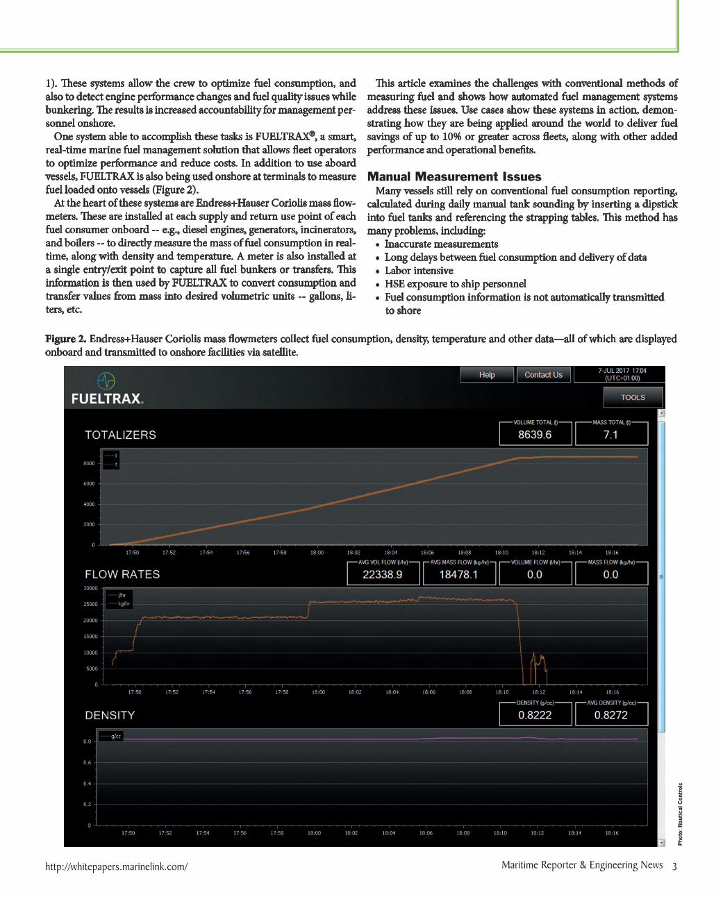
One system able to accomplish these tasks is FUELTRAX®, a smart, real-time marine fuel management solution that allows fleet operators to optimize performance and reduce costs. In addition to use aboard vessels, FUELTRAX is also being used onshore at terminals to measure fuel loaded onto vessels (Figure 2).
At the heart of these systems are Endress+Hauser Coriolis mass flow-meters. These are installed at each supply and return use point of each fuel consumer onboard -- e.g., diesel engines, generators, incinerators, and boilers -- to directly measure the mass of fuel consumption in real-time, along with density and temperature. A meter is also installed at a single entry/exit point to capture all fuel bunkers or transfers. This information is then used by FUELTRAX to convert consumption and transfer values from mass into desired volumetric units -- gallons, li-ters, etc.
This article examines the challenges with conventional methods of measuring fuel and shows how automated fuel management systems address these issues. Use cases show these systems in action, demon-strating how they are being applied around the world to deliver fuel savings of up to 10% or greater across fleets, along with other added performance and operational benefits.
Manual Measurement Issues
Many vessels still rely on conventional fuel consumption reporting, calculated during daily manual tank sounding by inserting a dipstick into fuel tanks and referencing the strapping tables. This method has many problems, including:
• Inaccurate measurements• Long delays between fuel consumption and delivery of data• Labor intensive• HSE exposure to ship personnel• Fuel consumption information is not automatically transmitted to shore
Figure 2. Endress+Hauser Coriolis mass flowmeters collect fuel consumption, density, temperature and other data—all of which are displayed onboard and transmitted to onshore facilities via satellite.
Phot
o: N
autic
al C
ontr
ols

4 MR White Papers Special Content Edition / Number One
Electronic Fuel Management
Inaccurate measurements are a natural consequence of manual tank sounding. The tank must be dead level, which is rare in the normal pitch and roll of a vessel at sea. The person making the measurement must record results with a high degree of accuracy, despite considerable potential for error. Fuel consumption is then assessed by calculating the difference between measurements, typically taken once a day. A single inaccurate reading will skew subsequent measurements.
Long delays between fuel consumption and delivery of data is ex-pected with the manual tank sounding measurement, as well as with all other methods of manual measurement. The vessel crew will only become aware of fuel consumption at least 24 hours after the fact, mak-ing it impossible to use these measurements to optimize consumption during real-time operations. Likewise, indications of fuel tampering or theft won’t be discovered by onshore management until long after the fact.
Labor intensive manual measurements are a poor use of the lim-ited manpower onboard vessels. Making and recording these measure-ments, and then calculating fuel consumption based on the difference from one measurement to the next, takes time. The written records which are produced must be transcribed and shared with onshore management, another time-consuming task.
Making manual measurements increases HSE exposure to ship per-sonnel, as they must gain access to the top of a tank, often during times when the vessel is pitching and rolling. Slippery conditions are com-mon, and falls are an ongoing risk. Personnel carrying out the mea-surements are exposed to hazardous fuel fumes on a regular basis.
Fuel consumption information is not automatically transmitted to shore, but typically sent with daily noon reports. This precludes the use of fuel data to provide immediate and automated optimizations for
fuel consumption.These are the main issues with manual measurement of fuel con-
sumption, each of which can be solved with an automated fuel man-agement system as described below.
Automated Fuel Management System DescriptionA crucial component of the automated fuel management system are
the Endress+Hauser Coriolis mass flowmeters. There are many differ-ent technologies for measuring flow, but Coriolis was selected because of the increased accuracy of mass flow measurements, as opposed to volumetric flow.
Mass flowmeters generate precise measurements and fuel quality readings, while volumetric flowmeters cannot differentiate measure-ment based on quality or spec. This is because Coriolis meters measure mass, along with density and temperature, used by the system to deter-mine fuel quantity and quality. In addition, many volumetric meters contain moving parts which require frequent maintenance.
While Coriolis mass flowmeters are available from many different vendors, Endress+Hauser was selected because of the quality and reli-ability of their meter, as well as their willingness to work with FUEL-TRAX to provide local stocking and to accommodate other business needs.
Each flowmeter sends mass flow, density, temperature, status and di-agnostic data to the FUELTRAX Field Termination Unit (FTU) via a Modbus RTU digital data link. The FUELTRAX FTU then sends this data to the Master Electronics Unit (MEU). The MEU processes pro-cesses the data from the mass flowmeters and sends it to the FUEL-TRAX satellite antenna for transmission to a shore-based data center via Iridium® satellite network. A GPS antenna is included with each
Figure 3. Fuel consumption and quality measurements are used onboard and onshore to optimize operations, track vessels across fleets and provide alerts.
Phot
o: N
autic
al C
ontr
ols

Self contained smart maritime solutions
The market-leading FUELTRAX smart, self-contained fuel management solution connects you to every vessel, anywhere in the world.Accurate and secure data insights, delivered in real-time, enable you to make informed decisions—fast. Achieve optimal fl eet performance with reduced fuel costs, increased uptime, and complete fuel security.
Enhance the performance of you fl eet. Talk to FUELTRAX today.
Compliance | Security | Performance
fueltrax.com
POWERFUL INSIGHTS INTO YOUR FLEET’S PERFORMANCE
2444EE FUELTRAX Ad 276x343_AW.indd 1 27/03/2018 21:27

Special Content Edition / Number One6 MR White Papers
Electronic Fuel Management
system antenna unit to transmit location data, which can be correlated with fuel consumption data. With FUELNET, this information is then overlaid on Google Maps to show a complete, minute-by-minute his-tory of the vessel’s movements, combined with exact information on what engines and generators are running, along with speed, and fuel consumption data for each.
The MEU performs the calculations necessary to turn the mass flow-meter data into actionable information to assist the crew onboard. A Wheelhouse Monitor displays this information and live recommenda-tions to optimize the vessel’s fuel consumption in relation to speed. A second display in the Engine Control Room (ECR) enables close watch of individual engine performance, as well as monitoring of real-time fuel consumption and quality. This display also allows the Chief Engi-neer to inspect the density quality during bunkers or transfer. A density siren is alarmed with strobe light to alert on fuel outside the predefined density ranges, indicating a fuel quality issues; an onscreen notification is then flashed on all FUELTRAX Monitors onboard.
Benefits of Automated Fuel Management The automated fuel management system onboard combined with the
web reporting platform FUELNET (Figure 3), work hand in hand to solve all of the problems associated with manual measurement systems and deliver the following additional benefits:
• Optimizes fuel consumption• Detects fuel quality • Deters fuel theft• Details and analyzes fuel consumption• Tracks vessel location in real-timeThe main benefit of an automated fuel management system is optimi-
zation of fuel consumption. The crew of the vessel uses the information
displayed on the FUELTRAX Wheelhouse Monitor to adjust the throt-tle and optimize consumption in real-time. As shown in the example below, this can cut consumption by up to 20% (Figure 5).
In many cases, optimizing fuel consumption must be balanced with-out sacrificing speed to ensure prompt delivery of cargo. An automated fuel management system provides the information required to reduce fuel consumption at the greatest maximum speed possible for the ves-sel. This delivers substantial financial benefits for on time delivery of the cargo with the least amount of fuel consumed during transit.
Critical fuel quality issues are promptly detected by automated fuel management systems. The Coriolis mass flowmeters used in these sys-tems measure density and temperature, revealing problems related to entrained air, or the presence of water or other contaminants. This in-formation is reported back to the FUELNET web platform for further review and analysis. Since the monitoring is carried out in real-time, problems are detected sooner and more efficiently than is possible with manual systems, allowing for timely remedial action.
Fuel accountability is a major issue for many fleet operators. Any signs of pilfering or slippage need to be detected in real-time. This is best achieved with an automated fuel management system with advanced capability to transmit fuel data, and visualized through a web-based platform accessible anywhere in the world. The system can also send email and text alerts to smartphones, tablets and other devices—allow-ing fleet managers and others to take action immediately and mitigate losses.
There are two main types of fuel accountability issues. The first occurs during fuel loading due to poor quality control or outright attempts at pilfering, or a combination of both. Air, water or other impurities are mixed with the fuel, which not only results in less fuel being loaded than expected, but can also affect the performance of engines and gen-
Figure 4. Crews activating the onboard settings at least 50% of time spent in Underway Mode achieved an average of 6% savings compared to typical fuel consumption.
Phot
o: N
autic
al C
ontr
ols

http://whitepapers.marinelink.com/ Maritime Reporter & Engineering News 7
erators. The density and temperature measurements from the mass flowmeter indicate issues, triggering the onboard density alarm as de-scribed above. The second accountability issue arises when unauthor-ized transfers are made in port or at sea, which can be detected by the mass flowmeter(s) placed at each loading point or a common header.
As shown in Figure 3, fuel consumption and quality data, along with vessel position, is transmitted via satellite link to shore, allowing for de-tailed analysis in a timely and efficient manner. In FUELNET, detailed reports are generated for data analysis revealing opportunities for fuel savings across the fleet. Alerts can also be generated to warn of existing or potential maintenance problems, thus allowing timely resolution.
The following use case shows how the FUELTRAX automated fuel management system is being used worldwide.
Use Case: Optimizing Four Main Modes of Operation
As shown in Figure 4, vessel data can be categorized into custom op-erating Modes, such as:
• “Underway” or “In-Transit”• Standby• Dock• Dynamic Positioning (DP)• DP outside 500m• Fuel Transfer• PortAdditional Modes can be customized according to the needs of the
vessel operator, which are automatically tracked and recorded based on the vessel operating parameters in FUELNET such as speed, engine run count, and GPS location.
For a fleet operator with 26 vessels, just four out of eight operating
modes accounted for nearly 80% of annual fuel spend. Through collab-oration with FUELTRAX Support team, the operator focused attention on the top four Modes to achieve the greatest fuel savings. The opera-tor saw significant savings across these modes by implementing opera-tional recommendations derived from FUELTRAX Support analysis and advanced analytics. In the following use case, we will examine the savings found by this operator in Underway Mode.
In August 2016, Underway Mode savings year-to-date were on average 6% per vessel. The operator achieved these savings through the crew’s activation of FUELTRAX onboard throttle op-timizations. Crews activating the onboard settings at least 50% of time spent in Underway Mode achieved an average of 6% savings compared to typical fuel consumption (Figure 4).
As each crew increases utilization of the onboard throttle opti-mizations, more savings can be achieved. For example, one ves-sel activating the onboard optimization settings 78% of the time spent in Underway Mode reported year to date savings over 14%.
By increasing the activation of the onboard optimization set-tings to 80% for all vessels, the operator has potential savings of up to 10% across all Underway Mode operations. The two on-board settings used are BestSpeedTM and BestEconomyTM, acti-vated by the crew when operating conditions permit (Figure 5). Further details about how these throttle settings reduce fuel con-sumption in real-time can be found in the following section.
With a goal of increasing savings in each of the four Modes, the op-erator performed similar operational studies of each Mode in collabo-ration with FUELTRAX Support team. In all Mode optimization cases such as this, the operational recommendations are validated by FUEL-NET data. Verified operational changes are replicated across the entire fleet to maximize savings.
Figure 5. The BestSpeed algorithm recommended the optimal maximum speed with minimum fuel consumption, resulting in savings of 21.3% compared to the typical burn rate.
Phot
o: N
autic
al C
ontr
ols

8 MR White Papers Special Content Edition / Number One
Optimizing Fuel consumption While in “Underway” Mode
As fuel consumption is analyzed by the system in real-time, appro-priate adjustments to the vessel’s operation can be made, reducing fuel consumption by 5-10% on average, and in some cases up to 20%. To assist the crew, the FUELTRAX automated fuel management system offers real-time recommendations on throttle placement in order to reduce consumption while vessel is in transit. These settings – Best-Speed™ and BestEconomy™ -- provide recommendations based on op-timal fuel consumption at maximum or reduced speed, respectively.
Each marine vessel has a non-linear speed versus fuel consumption curve, so optimal operation is not simply a case of maintaining the same speed at all times. In this example, the Captain was able to create the graph shown in Figure 5 by using the FUELTRAX onboard recom-mendations to adjust throttles in real-time. As the top graph illustrates, burn rate dropped from 60 gallon per hour (GPH) to 40 GPH, with very little reduction in speed as shown in the bottom graph.
The BestSpeed algorithm recommended the optimal maximum speed with minimum fuel consumption, resulting in savings of 21.3% compared to the typical burn rate. By calculating the optimal throttle setting, the decrease in speed from 10 knots was very minimal while resulting in large savings on total fuel consumed during the voyage.
ConclusionMore than 2000 Endress+Hauser Coriolis mass flowmeters have
been installed on over 200 vessels worldwide, resulting in an average fuel savings of 10% and a ROI of less than 12 months across fleets of 10 vessels or more. The meters have operated reliably with little to no maintenance required, as has the rest of the fuel management system.
Optimization of operations through analysis of the data provided by the FUELTRAX system can help fleet operators reduce consumption even more, by up to 20% in some cases. Because fuel consumption is typically a vessel’s second largest expense, a reliable fuel management system and analytics platform can cut total operating expenditure sub-stantially. In addition to savings and theft prevention, these automated systems also improve safety and allow operators to easily track vessel location at all times.
Electronic Fuel Management
Phot
o: N
autic
al C
ontr
ols
About the AuthorRuben DeLeon is the Product Support Director at Nautical Control Solutions, a position he has held since joining the company in January 2015. Prior to his current position, he worked for BP as an Instrumentation and Controls Engineer, and for the United Space Alliance as a Space Shuttle Flight Controller at NASA Johnson Space Center. Ruben holds a BS degree in Electrical and Computer Engineering from Baylor University.

62-67 Prime Mover Controls - Marine Propulsion.indd 67 7/29/2015 2:22:10 PM

10 MR White Papers Special Content Edition / Number One
WHITE PAPERSelecting Mechanically Attached Fittings
Ship Repair & Conversion
T raditional pipe-joining methods for shipbuilding are time-consuming and can pose significant safety concerns with the use of a torch or flame for welding and brazing pipe connections. Along with safety
concerns, these methods present efficiency, labor and regulatory chal-lenges. These challenges and concerns can be solved with the installation of mechanically attached fittings (MAFs), rather than pipe fittings that require welding or brazing. Advances in technology mean there are an array of fittings for installations and repairs for a variety of materials. These types of innovative fittings are versatile and can provide consistent connections without the need for fire watches or hot work permits. They promote substantial labor reduction with consistent first time quality and simplified testing/commissioning of systems.
DEFINING MAFSMAFs, or mechanically attached fittings, are pipe-joining methods that use alternative methods to keep pipes together with the same perfor-mance as welded or brazed fittings. They come in different varieties de-pending on anchoring and sealing methods, i.e. press, bite, and slip on.
INNOVATIONS IN MAFSOne of the recent innovations in MAF technology is the introduction of hybrid fittings, which combine features from bite-, press- and grip-type fittings. These fittings consist of a sleeve, grip ring, separator ring and sealing element. The grip ring with bidirectional teeth grips the outer surface of the pipe and locks the fitting to the pipe. The constant compression produces a positive, non-detachable mechanical joint.
TYPES OF MECHANICAL JOINTSThere are three types of connections for mechanical joints that are es-tablished in the “ABS Rules for Building and Classing” for steel vessels: pipe unions, compression couplings and slip-on joints.
MAFs are approved by class societies like the American Bureau of Shipping (ABS) and accepted by the United States Coast Guard (USCG) for marine and offshore applications to be specified throughout a classed vessel including engine rooms and cat A machinery spaces. These ap-proved shipboard applications include: potable water, compressed air, wet or dry fire main, fire sprinkler, fuel, lube oil, hydraulic oil and sea-water cooling systems. However, 2018 rule changes do not allow MAFs in Class A Machinery Spaces or Accommodation Spaces (footnote 2 in the chart to the right) for flammable fluids (flash point >60o C) for fuel, lube oil, hydraulic oil and heating oil, reversing a series of long stand-
ing applications. Slip-on joints face a number of additional restrictions.
APPLICATIONSBelow is the list of applications for the three types of mechanical joints, according to “ABS Steel Vessel Rules 2018.” The chart displays the kind of connection and how it relates to the eight major ship services, 33 listed ship applications and the service limitations imposed by the reg-ulatory bodies based on systems and not joint capabilities.
Phot
o: V
iega
LLC
Part 4 Vessel Systems and MachineryChapter 6 Piping SystemsSection 2 Metallic Piping 4-6-2
TABLE 10 Application of Mechanical Joints (1 July 2017)
The following table indicates systems where the various kinds of joints may be accepted. However, in all cases, acceptance of the joint type is to be subject to approval for the intended application, and subject to conditions of the approval and applicable Rules.
SystemsKind of Connections
Pipe Unions CompressionCouplings Slip-on Joints
Flammable Fluids (Flash Point 60°)1 Cargo oil lines (4) Y Y Y (11)
2 Crude oil washing lines (4) Y Y Y3 Vent lines (3) Y Y Y (13)
Inert gas4 Water seal effluent lines Y Y Y (16)
5 Scrubber effluent lines Y Y Y6 Main lines (2, 4) Y Y Y7 Distributions lines (4) Y Y Y
Flammable Fluids (Flash Point > 60°)8 Cargo oil lines (4) Y Y Y (11)
9 Fuel oil lines (3, 2) Y Y Y10 Lubricating oil lines (2, 3) Y Y Y11 Hydraulic oil (2, 3) Y Y Y (12)
12 Thermal oil (2, 3) Y Y YSea Water
13 Bilge lines (1) Y Y Y (8)
14 Water filled fire extinguishing systems (e.g., sprinkler systems) (3)
Y Y Y (7)
15 Non water filled fire extinguishing systems (e.g., foam, drencher systems) (3)
Y Y Y (7)
16 Fire main (not permanently filled (3) Y Y Y (7)
17 Ballast system (1) Y Y Y (9, 10)
18 Cooling water system (1) Y Y Y19 Tank cleaning services Y Y Y20 Non-essential systems Y Y Y
Fresh Water21 Cooling water system (1) Y Y Y (8)
22 Condensate return (1) Y Y Y (8)
23 Non-essential system Y Y YSanitary/Drains/Scuppers
24 Deck drains (internal) (6) Y Y Y (4)
25 Sanitary drains Y Y Y26 Scuppers and discharge (overboard) Y Y N (14)
Sounding/Vent27 Water tanks/Dry spaces Y Y Y28 Oil tanks (f.p.> 60°C) (2, 3) Y Y Y
Miscellaneous29 Starting/Control air (1) Y Y N30 Service air (non-essential) Y Y Y31 Brine Y Y Y32 CO2 system (1) Y Y N33 Steam Y Y Y (5, 15)
ABS RULES FOR BUILDING AND CLASSING STEEL VESSELS . 2018 431
By, Paul Switzer

http://whitepapers.marinelink.com/ Maritime Reporter & Engineering News 11
SEALING ELEMENT STUDYSome MAF manufacturers build a leak detection feature into the fit-ting, rather than the sealing element, to ensure that there are no false positives. However, in a recent study, manufacturers that used a modi-fied sealing element as a leak detection system on a ½” - 2” path had false positives approximately 70% of the time. This means that under the initial system pressure testing, even if a joint had not been pressed, it will still hold pressure for a short amount of time, sometimes even hours or months. The other major issue with using a modified sealing element is that they do not use the three components (sealing element, separator and bite ring) in their 2-½”- 4” sizes. Because of this, the tolerance is extremely tight on those sizes and many users have issues getting the pipe inserted into the fitting.
When the leak indicator is built into the fitting itself, this provides a repeatable and reliable indication of an unpressed joint 100 percent of
the time. Upon pressing, the alloy is being squeezed closed or reformed into the fitting during the press, which removes the leak path without depending on the sealing element to do so.
TYPES OF PRESS FITTINGSPress fittings are an example of compression couplings. Press fittings come in a variety of types and with several design considerations to take into account. Copper tube size (CTS) systems sometimes feature a single-side press sealing element. Double-sided press fittings in a CTS system feature a cylindrical pipe guide to insure alignment, protect the sealing element and provide double the mechanical anchoring to the tubing.
Iron pipe size systems (IPS) feature a bite ring to bite against pipe to provide a positive mechanical attachment to pipe. They also have a separator ring, which protects the sealing element from damage during
Part 4 Vessel Systems and MachineryChapter 6 Piping SystemsSection 2 Metallic Piping 4-6-2
TABLE 10 (continued)Application of Mechanical Joints (1 July 2017)
AbbreviationsY – Application is allowed
N – Application is not allowed
Footnotes – Fire Resistance Capability:If mechanical joints include any components which readily deteriorate in case of fire, they are to be of an approved fire resistant type under consideration of the following footnotes:
1 Inside machinery spaces of category A – only approved fire resistant types.
2 Not inside machinery spaces of category A or accommodation spaces. May be accepted in other machinery spaces provided the joints are located in easily visible and accessible positions.
3 Approved fire resistant types except in cases where such mechanical joints are installed on exposed open decks, as defined in SOLAS II-2/Reg. 9.2.3.3.2.2(10) and not used for fuel oil lines.
4 In pump rooms and open decks – only approved fire resistant types.
Footnotes – General:5 Slip type slip-on joints as shown in 4-6-2/Table 9, may be used for pipes on deck with a design pressure of 10 bar
or less.
6 Only above bulkhead deck of passenger ships and freeboard deck of cargo ships.
7 In accessible locations at all times under normal condition.
8 In accessible locations in machinery spaces, container holds carrying non-dangerous goods, shaft tunnels, pipe tunnels, etc.
9 In accessible locations in machinery spaces, shaft tunnels, pipe tunnels, etc. In pipelines located within other ballasttanks. For tankers, in clean or dirty ballast lines provided lines terminate in cargo pump room [see 5C-1-7/5.3.2(a) of the Rules for prohibitions].
10 Inside pump room – only with approved fire resistant types.
11 Within cargo tanks.
12 Not permitted in steering gear hydraulic systems, otherwise Class III systems only.
13 On vent risers on decks only.
14 Accessible location inboard of required shell valve(s) may be permitted. Slip-on joints are not permitted where there are no shell valve(s), for example, when outboard end >450 mm below freeboard deck or outboard end < 600 mm above summer waterline. For such instances, the overboard piping is required to be of substantial thickness per definition in 4-6-2/9.13.3.
15 Permitted in Class III piping in machinery spaces of Category A, other machinery spaces, accommodation spaces and open deck.
16 On the open deck only.
432 ABS RULES FOR BUILDING AND CLASSING STEEL VESSELS . 2018
Phot
o: V
iega
LLC

12 MR White Papers Special Content Edition / Number One
Ship Repair & Conversion
the pressing and is radially pressed to complete the mechanical connection. QUALIFYING A MAFMAFs are qualified based on temperature and pressure capabilities. They are also classified according to different thresholds as Class I (high temperature and pressure capability), Class II (mid temperature and pressure capability) and Class III (low temperature and pressure capability). These are defined by the operational requirements of the systems in which they are used.
MAF qualification is based on restrictive testing that verifies system performance, longevity and safety. When selecting what type of MAF to include in the specification process, it is important to consider ap-provals, performance, ease of use, consistency, tooling, environment and fitting cost.
SAFETY AND QUALITY BENEFITS OF SELECTING MAFSMAFs are safe, efficient and eliminate the need for hot work, fumes and gases. They also do not require bulky equipment to take down, relocate and setup. Installing MAFs reduces lifting and moving heavy objects, which lightens the load on the labor force as well as reduces welding-related accidents and injuries. The installer is mobile and can move
deck to deck installing fittings using a hand-held battery tool, as well as a separate spark-free tool for hazardous/confined spaces.
Expediting pipe installations by using MAFs allows other trades like painting, insulation and electrical to work in the same area, therefore advancing the entire project schedule and not just the piping. MAFs are a good solution for reducing a ship’s initial build cost for new construc-tion, as well as reducing the overall cost of ownership when utilized for retrofits, modernization and permanent repairs while underway. Pressed pipe fittings can also be tied into existing piping systems, elimi-nating the need to re-pipe the entire ship.
Often times, emergency repairs on a ship are temporary and per-formed by the crew. Some MAFs provide a permanent repair in emer-gency situations. These can be completed the first time and the ship does not have to update the repair at a future date.
System integrity and reliability are also improved with the use of MAFs because this type of fitting provides a consistent joint each time in a permanent installation. They offer leak-free performance with no false positives that reduces any callback work and ultimately reduce the total cost of ownership. MAF connections can be made wet or dry, and the quality of the joint is not compromised by the position of the pipe or the presence of liquids. There are fire-approved type MAFs that withstand service conditions that a system is anticipated to experience, including fire and shock.
LABOR AND COST BENEFITS OF SELECTING MAFSIn addition to safety, MAFs offer a variety of other benefits, including reduced initial build cost and reduced cost of ownership. Well-designed MAFs insure consistent first time quality connections and do not rely on the skill level of the installer. Commissioning of the system is achieved by
Phot
o: V
iega
LLC
Phot
o: V
iega
LLC

The most innovative, mechanically-attached � ttings for the marine world. Let’s face it. With tighter deadlines, bigger budget constraints, and a rising tide of labor scarcity, traditional welding methods have gotten in the way of timely building and repair. Finally, there’s a faster, safer, simpler alternative that brings more certainty and success to the industry. MegaPress CuNi is a new press � tting system designed for copper nickel application aboard ships. It’s a sea of change for the marine world. Those who harness it will be those who rule with con� dence. Viega. Connected in quality.
Learn more about how MegaPress CuNi can help you rule the sea at viega.us/RuleNow
Rule the Sea.Introducing MegaPress® CuNi.

14 MR White Papers Special Content Edition / Number One
Ship Repair & Conversion
hydrostatic testing. Unpressed connections are easily pressed while the system remains pressurized without the need to stop the test, flush the system, repair and repeat the hydrostatic procedure. Therefore, the time and associated costs of installation can be largely minimized by using sys-tems that incorporate these capabilities. Also, the costs and time for train-ing installers for MAFs is significantly less than for welding. MAFs also reduce a number of equipment costs compared to welding and threading systems, such as the cost of threading machines, gases and welding rods.
MCAA Labor Estimating Guides show a labor reduction of solder versus press of 70-77% and weld versus press of 90-93%, meaning users can install more piping with less labor, resulting in an expedited instal-lation and delivery schedule.
THE FUTURE OF MAFSIn the coming years, innovative technology, like hybrid MAFs, will eventually rewrite the industry rules. By combining the best technol-ogy and qualities from bite-, press- and grip-type fittings, the reliable and strong connections made by hybrid fittings have the potential to create new standards for building and servicing ships.
CONCLUSIONAll types of MAFs are not equal. There are inherent differences be-tween compression couplings, which include swage, press, bite and flared type, and slip-on joints, which include bite, machine grooved and slip types. It is important to select reliable, safe and easy-to-install MAFs that will advance shipbuilding technology into the twenty-first century and keep shipbuilders profitable and on schedule with existing labor pools.
About Viega:The Viega Group, with a tradition of innovation for more than 115 years, has more than 4,000 employees worldwide and is among the leading manufacturers of pipe fitting installation technology. In metal press systems for industrial, commercial and residential projects, the company is the global market leader. In the U.S., Viega LLC employs more than 600 people and offers more than 3,000 products. These include Viega
ProPress® for copper and stainless, Viega MegaPress® for carbon steel and stainless pipe, the Viega PureFlow® System including PEX and fittings in high-performance polymer and Zero Lead bronze, as well as MegaPress CuNi and SeaPress® systems for marine applications.Viega also specializes in the design, production and installation of ProRadiant™ heating and cooling systems, and offers In-Wall Flushing Technology including carriers and flush plates.
For more information, visit viega.us.
Phot
o: V
iega
LLC
Phot
o: V
iega
LLC
Author: Paul Switzer, Manager, Shipbuilding and Offshore at Viega