A Sensor Network for Buildings Based on the DALI Bus
52
Sensor/DALI Bus 1 A Sensor Network for Buildings Based on the DALI Bus Yuan Ma and Darold Wobschall Esensors Inc. and University at Buffalo Buffalo, NY www.eesensors.com Sensors Application Symposium (SAS) San Diego, Feb. 2006 b
Transcript of A Sensor Network for Buildings Based on the DALI Bus

Sensor/DALI Bus 1
A Sensor Network for BuildingsBased on the DALI Bus
Yuan Ma and Darold Wobschall
Esensors Inc. andUniversity at BuffaloBuffalo, NY
www.eesensors.com
Sensors Application Symposium (SAS)San Diego, Feb. 2006
b

Sensor/DALI Bus 2
Goals
� To develop and demonstrate a an extended version of the DALI bus suitable for sensor data acquisition.
� To provide a conversion of the DALI to IEEE 1451 format.

Description of Standard DALI Bus
� DALI: Digital Addressable Lighting Interface
� Developed for building lighting control, especially ballasts
� Two-wire bus: 12/15 volts with 250 mA current limit
� Master data is standard RRZ (like UART, but bi-phase encoding, 1200 bits/sec)
� Slave (remote) device shorts bus for logic 0.
� 16-bit command with 8-bit return, with timeouts
� Operates up to 300 meters (14 to 22 gage wire)
Sensor/DALI Bus 3

Standard DALI Block Diagram
Sensor/DALI Bus 4

DALI Bus Waveform
Sensor/DALI Bus 5

DALI Bus Characteristics
� Data and power on two wires
� Oriented to lighting control
� Many DALI device suppliers
� Noise immune (low data rate, higher voltage/current bus)
� Data return too slow and limited for sensor data
Sensor/DALI Bus 6

Sensor/DALI Bus 7
DALI Master (Driver) Interface Circuit

Sensor/DALI Bus 8
DALI Remote (Slave) Interface Circuit
Isolator option shownBipolar diodebridge option shown

Extended DALI Concept
� Use same voltage/current limit as standard DALI
� Be compatible with standard DALI (co-existence on same bus)
� Increase speed to 9600 Bits/sec (standard DALI ignores)
� Increase data return (7+ bytes)
� Provide TEDS (IEEE 1451.4) for ID
� Provide gateway to IEEE 1451.0 (Dot 0) protocol
� Also provide wireless option
Sensor/DALI Bus 9

Sensor/DALI Bus 10
A review of the
IEEE 1451 Smart Transducer Concept
Analog /Digital
Conversion
1451.0 Control Logic
Sensor
TEDS
Signal Processing
1451 .X Comm Layer
Transducer Interface Module (TIM)
Network Capable Application Processor (NCAP)
1451.X Comm Layer
1451.0 Routing, signal
processing , TEDS mgt
Message Abstraction , TCP/IP, Web
Server Embedded Application
1451 .X Transport Mechanism
Remote Computer
LAN
From Smart Sensor Systems Master=NCAP, Slave=TIM

Sensor/DALI Bus 11
IEEE 1451.0 (Dot 0) Format
� Required: Transducer Electronic Data Sheet (TEDS)[Memory block with defined format]� MetaTEDS� Channel TEDS� Calibration TEDS (unless SI units)� Xdr-name TEDS� Phy TEDS� Also optional TEDS
� Data Transmission [specific octet format]� TEDS/Status requests� Triggering and configuration� Sensor read commands and data return� Actuator write commands and data sending
Sensor/DALI Bus 12
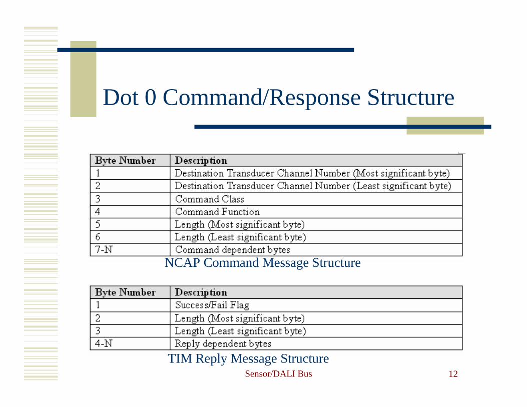
Dot 0 Command/Response Structure
NCAP Command Message Structure
TIM Reply Message Structure

Sensor/DALI Bus 13
Simplified (Dot 4) TEDS(developed for IEEE 1451.4)
� UUID (Universal Unique Identifier)Supplied by EEPROM (DS2433) manufacturer (6 bytes)
� Basic TEDS (8 bytes)� Model Number (15 bits)
� Version Letter (5 bits, A-Z)
� Version Number (6 bits)
� Manufacturer ID (14 bits)
� Serial Number (6 bits)
� Manufacturer’s TEDSSensor type and calibration parameters (16 bytes)
Dot 4Conversion to Dot 0 TEDS done in NCAP

Sensor/DALI Bus 14
Block Diagram of Extended DALI Bus

Extended DALI Data Frame Format
Sensor/DALI Bus 15
Control Field Data Field CRC Field ACK Filed
Arbitration (1-byte)
Description + Length (1byte)
Slave ID(1 byte)
Command/Data(N bytes)
CRC(2 bytes)
FF hex(1 byte)

Examples of Master Slave Responses
Sensor/DALI Bus 16
Data FieldSlave address
0x01(inquiry Command)
Illumination code Temperature code
Data Field
Slave address
0x01(Answer Inquiry)
Illumination code
Illumination Data
Temperature code
Temperature Data
Slave Response (Illumination and Temperature Data to Master)
Master Requests Illumination and Temperature from Slave

Sensor/DALI Bus 17
Data Readout Examples(via Internet)

Amperometric Sensor on DALI bus
Sensor/DALI Bus 18

Sensor/DALI Bus 19
Prototype DALI Master and Slave Circuit Boards

Sensor/DALI Bus 20
TEDS Compiler
� Part of Ph. D. thesis of
Wai Liu
(Univ. at Buffalo)
� Copy of thesis is
available free

Sensor/DALI Bus 21
References
� Wai Liu, “Design of TEDS Writer, Reader and Testing System for Transducer Interface Modules based on the IEEE 1451 Standard“, Ph. D. thesis (SUNY/Buffalo, EE Dept), May 2006.
� IEEE Std.
� D. Wobschall, “A Minimal Dot4 NCAP with a Compatible Sensor Bus”, SiCon/05 (Houston).
� www.eesensors.com/IEEE1451

Sensor/DALI Bus 22
Summary
� We have developed an extension of the DALI bus which is suitable for acquiring sensor data.
� Bus was tested with bus consisting of mix of sensors and conventional DALI lighting devices
� The IEEE 1451 protocol with the Dot 4 TEDS and Dot 0 on the network was demonstrated.
Further information: [email protected]

Sensor/DALI Bus 23
Backup Slides
www.eesensors.com

Sensor/DALI Bus 24
IEEE 1451 – the Universal Transducer Language
� Over 100 sensor network protocols in common use
� Narrow solutions and borrowed protocols have not worked
� IEEE 1451 is the best universal solution
� Sensor engineers in the fragmented sensor industry need a simple method of implementation
� How can it be done?
The Tower of Babel

Sensor/DALI Bus 25
IEEE 145.0 (Dot 0) Advantages
� Comprehensive enough to cover nearly all sensors and actuators in use today (not 20/80% approach)
� Many operating modes(buffered, no-buffer, grouped sensors, timestamps, timed data, streaming …)
� Extensive units, linearization and calibration options
� Multiple timing and data block size constraints handled.
� Compatible with most wired and wireless sensor buses and networks (point-to-point, mesh, TIM-to-TIM, mixed networks).
� Efficient binary protocol (especially suitable for wireless)

Sensor/DALI Bus 26
But the Complexity!
� A comprehensive standard is necessarily complex
� There was little adoption of the original IEEE 1451.2 (TII) standard because of its perceived complexity
� Manual preparation of the TEDS is not practical
� A TEDS compiler is needed� A compliance test procedure is also desirable
to prove that the design is correctMunch –The scream

Sensor/DALI Bus 27
TEDS Format
� General format for each TEDS section:
� Binary TEDS Tuple format for each data block:
Type-Length-value (TLV)
Example: 01 02 A3 04
Field type is 1, Length is 2 bytes, field value is “A304” hex
� Field example: Meta-TEDS (TEDS # 1)
13: Number of Implemented Transducer Channels (default=1)

Sensor/DALI Bus 28
TEDS Sections Implemented
� Meta TEDS
� Meta ID TEDS
� Transducer Channel TEDS
� Transducer Channel ID TEDS
� Calibration TEDS
� Calibration ID TEDS
� XdrcName TEDS
Referenced by TEDS section/access code (e.g. #1 for Meta-TEDS)

Sensor/DALI Bus 29
SI Based Units
Standard Transducer Units(binary format)

Sensor/DALI Bus 30
Meta-TEDS Writer Screen

Sensor/DALI Bus 31
Channel/Calibration TEDS(for linear sensors)

Sensor/DALI Bus 32
Text Based TEDS(human readable)
� Meta ID TEDS
� Transducer Channel ID TEDS
� Calibration ID TEDS
� XdcrName TEDS (required)
ASCII or XML – multiple languages availableEN: English
QC: computer language (additional data)

Sensor/DALI Bus 33
TEDS Reader

Sensor/DALI Bus 34
IEEE 451 TIM Compliance Tester
� TIM (Transducer Interface Module) is most complex and done by sensor design engineers
(TIM tester can be used by the few NCAP designers)
� Tester verifies compliance of a TIM to IEEE 1451.0 (Dot 0) protocol
� Focus is on TEDS checking and data transfer format� Physical device compliance not checked (part of
other standards, e.g. RS485, Bluetooth)� Tester uses serial bus (RS232)� Testing may be done by Internet

Sensor/DALI Bus 35
Network side (NCAP) options(wired)
� Internet/Ethernet
� PC Readout
� Industrial
network
All use Dot 0 protocol
Sensor/DALI Bus 36
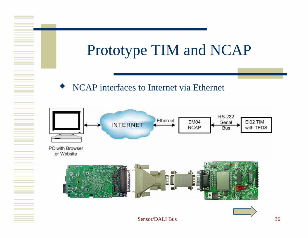
Prototype TIM and NCAP
� NCAP interfaces to Internet via Ethernet

Sensor/DALI Bus 37
TEDS Compliance TesterRetrieval Sequence
� Read TIM Version� Read IEEE p1451.0 Version� Query Meta ID TEDS� Query Meta TEDS� Get Meta TEDS Content� Query Transducer Channel TEDS� Get Transducer Channel TEDS Content� Query Calibration TEDS� Get Calibration TEDS Content� Query Transducer Channel ID TEDS� Query Calibration ID TEDS

Sensor/DALI Bus 38
TIM Tester (Operating Mode)
Similar test sequencefor Idle Mode
Sensor/DALI Bus 39
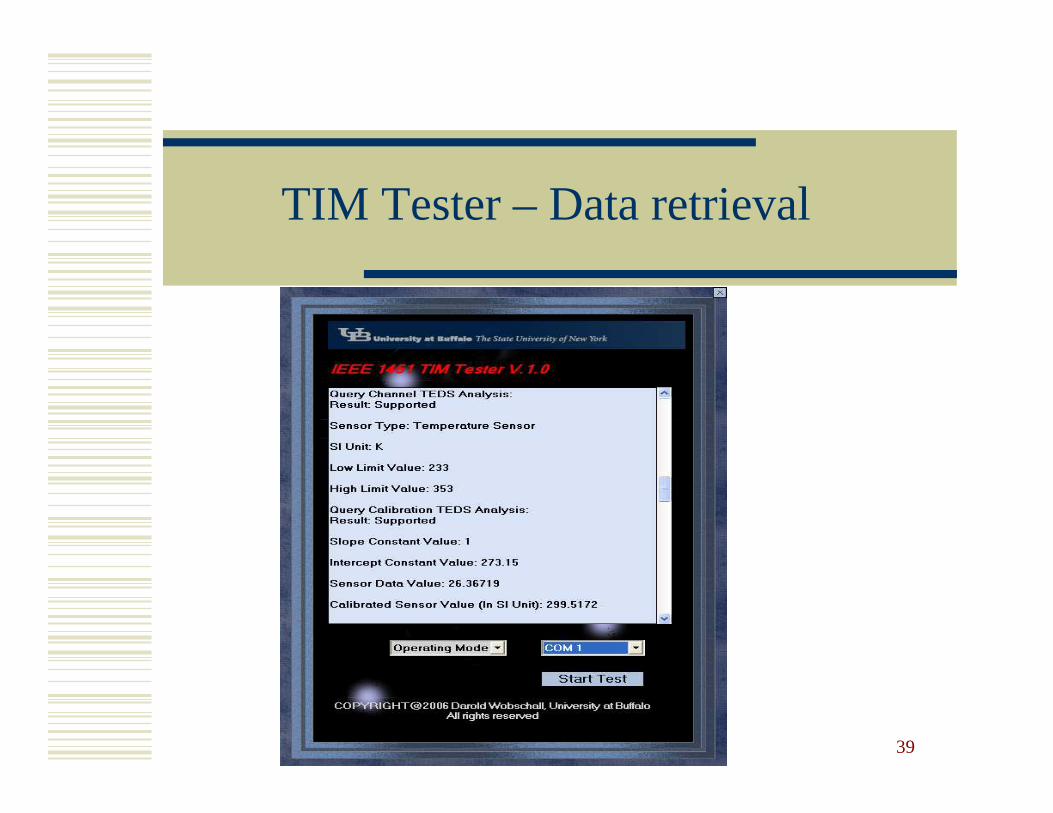
TIM Tester – Data retrieval

Sensor/DALI Bus 40
Serial Bus Formatand Relation to other Networks
� Tester uses RS232 serial bus only but…� Interfaces to other physical devices (USB, RS485,
Bluetooth, Zigbee, ….) available.� TEDS retrieval is one feature� Sensor data read (protocol check) for each channel:
Idle mode – full scale value of sensor reading(Checked against TEDS, error flag is not correct)
Operating mode – actual sensor reading(Must be within sensor range)

Sensor/DALI Bus 41
Example –Wireless Connection
� Wireless modules with RS232 I/Owhen connected to Dot 2 TIMS are similar to IEEE 1451.5 TIMs (wireless version of IEEE 1451).
� Data format and TEDS are the same (both follow the Dot 0 standard)..
Dot 5 TIM built from a Dot 2 TIM and wireless transceiver

Sensor/DALI Bus 42
Alternative Tester forDot 4 TEDS
Dot 4
IEEE 1451.4 (only) does not use the Dot 0 format TEDS.This is a small, TEDS-only version (no digital data format is specified by the standard).

Sensor/DALI Bus 43
Dot 4 TEDS Writer and Reader(PC Screens)
Writer ReaderDot 4

Sensor/DALI Bus 44
Harmonization of IEEE 1451 with other sensor standards

Sensor/DALI Bus 45
UUID Format
Meta-TEDS (#1), field 4 (10 bytes)

Sensor/DALI Bus 46
Block Diagram of a Prototype Dot 2 TIM or Smart Transducer

Sensor/DALI Bus 47
Prototype Dot 2 (RS232) TIM(with 2 sensors and 1 actuator)
Hall effectPhotoRelay

Sensor/DALI Bus 48
TEDS/Test Data File Save

Sensor/DALI Bus 49
References
� Wai Liu, “Design of TEDS Writer, Reader and Testing System for Transducer Interface Modules based on the IEEE 1451 Standard“, Ph. D. thesis (SUNY/Buffalo, EE Dept), May 2006.
� R. Johnson, et al “A Standard Smart Transducer Interface”http://ieee1451.nist.gov/Workshop_04Oct01/1451_overview.pdf
� IEEE Std. 1451.2-1907 “IEEE Standard for a Smart Transducer Interface for Sensors and Actuators – Transducer to Microprocessor Communication Protocols and Transducer Electronic Data Sheet (TEDS) Format” http://ihome.ust.hk/~yangrd/pdf/ieee14512.pdf
� R. Frank “Understanding Smart Sensors”, 2nd ed, Artech House (2000)
� D. Wobschall, “Websensor Design – Smart sensors with an Internet Address” Proceeding Sensors Expo (Philadelphia, Oct. 2001)
� D. Wobschall, “A Minimal Dot4 NCAP with a Compatible Sensor Bus”, SiCon/05 (Houston).
� www.eesensors.com/IEEE1451

Sensor/DALI Bus 50
Original IEEE 1451.2 (Dot 2)with 10-pin Transducer Independent Interface (TII)
Note: New name is TIM (Transducer Interface Module)
Sensor/DALI Bus 51
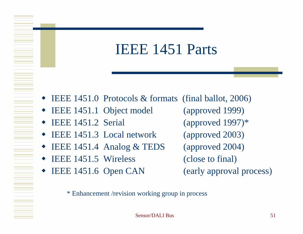
IEEE 1451 Parts
� IEEE 1451.0 Protocols & formats (final ballot, 2006)� IEEE 1451.1 Object model (approved 1999)� IEEE 1451.2 Serial (approved 1997)*� IEEE 1451.3 Local network (approved 2003)� IEEE 1451.4 Analog & TEDS (approved 2004)� IEEE 1451.5 Wireless (close to final)� IEEE 1451.6 Open CAN (early approval process)
* Enhancement /revision working group in process

Sensor/DALI Bus 52
� END