100W DMX/RDM/DALI Full-Colour (RGBW) Dimmable LED Driver ...

Helvar | Data is subject to change without notice. | HELVAR DRIVER CONFIGURATOR 2.0 UG22124 1A 12/09/2017 1
PARAMETER SETTING WITH HELVAR DRIVER CONFIGURATOR
The Helvar Driver Configurator tool is divided in tabs for ease of use. Once device data is red, all functions not supported by the connected driver will appear as disabled and not accessible. The configuration tool includes text fields where parameters can be modified: by typing into information fields or pressing buttons to select/enable/disable functionalities. An “Upload” button in the “Device Parameters” tab uploads the modified parameters into the connected driver.
The program is used to control and program manually or automatically the connected drivers. Also driver address copying and physical driver identification features are available.
The program is used for customizing the LED driver for a specific need. Following selection of configurable LED driver parameters are available:
• Device identificaton & addressing• Driver settings• Automatic programming• Command programming• iC & DALI settings
iC & DALI settings allow to configure LED module parameters and driver parameters affecting the control of colour temperature in order to ensure a proper operation of colour and intensity control with Helvar Tunable White LED drivers (iC Series).
ELECTRICAL CONNECTION
Safety warning: remember to turn off the electricity before disconnecting or connecting devices. Only a trained person should be doing this!
The connection between the programming PC and the driver can be established for example with the following setup:
Devices needed:• DALI power supply (ie. Helvar 401, 402 or Helvar iDim Solo
403; iDim Solo 403 is used in this example.)• Helvar USB to DALI Interface Unit 510 or Helvar DIGIDIM
505 Serial interface.
For installation of the software, run the installation file. Supported operating system is Microsoft Windows 7 and compatible.
Preliminary setup: The USB to DALI Interface unit is connected to the DALI power supply, and the driver under configuration with DALI bus. Please ensure correct polarity of the USB to DALI Interface and DALI power supply! Helvar LED driver DALI bus connections are unipolar and require no special attention.The DALI power supply and the driver under configuration must also be provided with mains power.
Example setup to use when using Helvar DALI Driver Configurator:
Helvar Driver ConfiguratorUSER GUIDE
This user guide provides instructions on how to program Helvar LED driver parameters, how to configure iC colour control features, and provides guidance for the use of the Helvar Driver Configurator program.
USB to DALI interface
Helvar (iC) LED Driver
LED Module
LED Module
DALI power supply

Helvar | Data is subject to change without notice. | HELVAR DRIVER CONFIGURATOR 2.0 UG22124 1A 12/09/2017 2
MAIN WINDOW
The main part of the Configurator window is common for all sub tabs showing selected adapter selector, address selector, scan bus, assign short addresses, read data and identify buttons.
MAIN WINDOW BUTTON FUNCTIONALITIES
Adapter selector Select USB or COM port for DALI communication. USB selection always refers to a connected Helvar 510 USB to DALI converter, while COM port might be any serial device. The user should know the actual COM port for their serial to DALI converter.
Address selector Select the DALI address of the device. Use “Scan bus” to populate the list (initially the list is empty).
Scan Bus Scans through DALI short address space to find devices connected to the selected DALI adapter. Updates the address list with found short addresses and device names.
Assign short ddresses When checked, the “Scan Bus” process (see above) assigns new short addresses to devices that lack them or devices with conflicting addresses. Already assigned unique short addresses are left as they are. Note: it’s also possible to configure unaddressed devices if they are the only device currently on the DALI bus.
Read Data Reads the current configuration from the selected device. The configuration can then be edited in “Device Parameters” tab below.
Identify The selected LED driver changes between MIN and MAX values, so it’s possible to physically identify which device is currently being configured. Use this feature together with address selector to program a desired driver in an installation.
CONFIGURATOR FEATURES

Helvar | Data is subject to change without notice. | HELVAR DRIVER CONFIGURATOR 2.0 UG22124 1A 12/09/2017 3
DEVICE PARAMETERS
After reading the configuration from a selected device using “Read Data” button, the “Device Parameters” tab displays the features of the device which can be altered. Please note that only available settings for the connected device model are displayed.
GENERAL BUTTONS
Load Load configuration from file. The parameters supported by the device type will be shown in “Device Parameters” tab.
Save Save configuration to a file.
Upload Uploads the current parameters to the device selected by “Adapter” and “Address” selectors.
DEVICE DEPENDENTLY AVAILABLE SETTINGS
Switch Control Enabled Selecting this radio button enables the functionality if it is supported by the LED driver. • Power On Last Level Enabled – selecting this lights return to the last DALI level used before the
power break.
Iset by SW Select this to override current setting via multipurpose Iset-terminal in the driver. The same driver terminal can then be utilized for other functions like the NTC operation.
Output current Type in the driver output current in mA. If the value is outside of the LED driver output current range the driver will use the closest specified value. The drivers use the smallest output current as a default.
NTC Enabled Select this feature to protect luminaire from critical high temperatures.
NTC value Type in the NTC value corresponding to the trigger temperature. If supported the NTC value is speci-fied on each Helvar LED driver datasheet.
CLO Enabled Select this to compensate against light depreciation of the light source. CLO Start level (%) – type in desired light level to maintain Constant Light OutputCLO Life Time (x1000 h) – type in desired lifetime in thousand hours. This time describes when the output current needs to be on 100% level to maintain the selected Constant Light Output.
Write short address When checked, also a short address is set during upload. This can be is useful if you want to copy the whole state of another device including the short address (read data from one device, select a new compatible device and upload with this option checked). If you want to change device address to some other value see “New short address” in “Control” tab.
CONFIGURATOR FEATURES
Helvar | Data is subject to change without notice. | HELVAR DRIVER CONFIGURATOR 2.0 UG22124 1A 12/09/2017 4
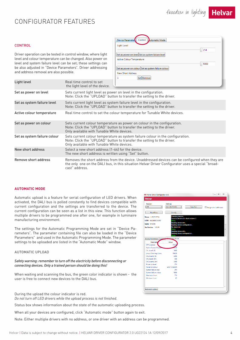
CONTROL
Driver operation can be tested in control window, where light level and colour temperature can be changed. Also power on level and system failure level can be set; these settings can be also adjusted in “Device Parameters”. Driver addressing and address removal are also possible.
Light level Real time control to set the light level of the device.
Set as power on level Sets current light level as power on level in the configuration. Note: Click the “UPLOAD” button to transfer the setting to the driver.
Set as system failure level Sets current light level as system failure level in the configuration. Note: Click the “UPLOAD” button to transfer the setting to the driver.
Active colour temperature Real time control to set the colour temperature for Tunable White devices.
Set as power on colour Sets current colour temperature as power on colour in the configuration. Note: Click the "UPLOAD" button to transfer the setting to the driver. Only available with Tunable White devices.
Set as system failure colour Sets current colour temperature as system failure colour in the configuration. Note: Click the “UPLOAD” button to transfer the setting to the driver. Only available with Tunable White devices.
New short address Select a new short address (1-64) for the device. The new short address is written using “Set” button.
Remove short address Removes the short address from the device. Unaddressed devices can be configured when they are the only one on the DALI bus, in this situation Helvar Driver Configurator uses a special “broad-cast” address.
AUTOMATIC MODE
Automatic upload is a feature for serial configuration of LED drivers. When activated, the DALI bus is polled constantly to find devices compatible with current configuration and the settings are transferred to the device. The current configuration can be seen as a list in this view. This function allows multiple drivers to be programmed one after one, for example in luminaire manufacturing environment.
The settings for the Automatic Programming Mode are set in “Device Pa-rameters”. The parameter containing file can also be loaded in the “Device Parameters” and used in the Automatic Programming Mode. The parameter settings to be uploaded are listed in the “Automatic Mode” window.
AUTOMATIC UPLOAD
Safety warning: remember to turn off the electricity before disconnecting or connecting devices. Only a trained person should be doing this!
When waiting and scanning the bus, the green color indicator is shown - the user is free to connect new devices to the DALI bus.
CONFIGURATOR FEATURES
During the upload the colour indicator is red. Do not turn off LED drivers while the upload process is not finished.
Status box shows information about the state of the automatic uploading process.
When all your devices are configured, click “Automatic mode” button again to exit.
Note: Either multiple drivers with no address, or one driver with an address can be programmed.
Helvar | Data is subject to change without notice. | HELVAR DRIVER CONFIGURATOR 2.0 UG22124 1A 12/09/2017 5
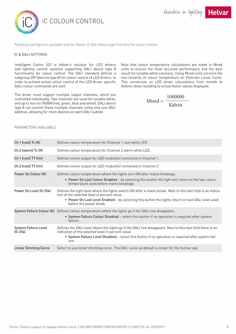
Following settings are available only for Helvar iC DALI device type 8 drivers for colour control.
IC & DALI SETTINGS
PARAMETERS AVAILABLE
Ch 1 (cool) Tc (K) Defines colour temperature for Channel 1 cool white LED.
Ch 2 (warm) Tc (K) Defines colour temperature for Channel 2 warm white LED.
Ch 1 (cool) TY (lm) Defines lumen output for LED module(s) connected in Channel 1.
Ch 2 (cool) TY (lm) Defines lumen output for LED module(s) connected in Channel 2.
Power On Colour (K) Defines colour temperature where the lights turn ON after mains breakage.• Power On Last Colour Enabled – by selecting this button the light will return to the last colour
temperature used before mains breakage.
Power On Level (0-254) Defines the light level where the lights switch ON after a mains break. Next to this text field is an indica-tion of the selected level in percent value.
• Power On Last Level Enabled – by selecting this button the lights return on last DALI level used before the power break.
System Failure Colour (K) Defines colour temperature where the lights go if the DALI line disappears.• System Failure Colour Disabled – select this button if no operation is required after system
failure.
System Failure Level (0-254)
Defines the DALI level where the lights go if the DALI line disappears. Next to this text field there is an indication of the selected level in percent value.
• System Failure Level Disabled – select this button if no operation is required after system fail-ure.
Linear Dimming Curve Select to use linear dimming curve. The DALI curve as default is linear for the human eye.
Intelligent Colour (iC) is Helvar’s solution for LED drivers and lighting control systems supporting DALI device type 8 functionality for colour control. The DALI standard defines a subgroup 209 (devices type 8) for colour control of LED drivers. In order to achieve actual colour control of the LED driver, specific DALI colour commands are sent.
The driver must support multiple output channels, which are controlled individually. Two channels are used for tunable white, and up to four for RGBW (red, green, blue and white). DALI device type 8 can control these multiple channels using only one DALI address, allowing for more devices on each DALI subnet.
Note that colour temperature calculations are made in Mired units to ensure the most accurate performance and the best result for tunable white solutions. Using Mired units corrects the non-linearity of colour temperature on Plancian Locus Curve. This conversion on LED driver calculations from mireds to Kelvins show rounding to actual Kelvin values displayed.
iC COLOUR CONTROL
Helvar | Data is subject to change without notice. | HELVAR DRIVER CONFIGURATOR 2.0 UG22124 1A 12/09/2017 6
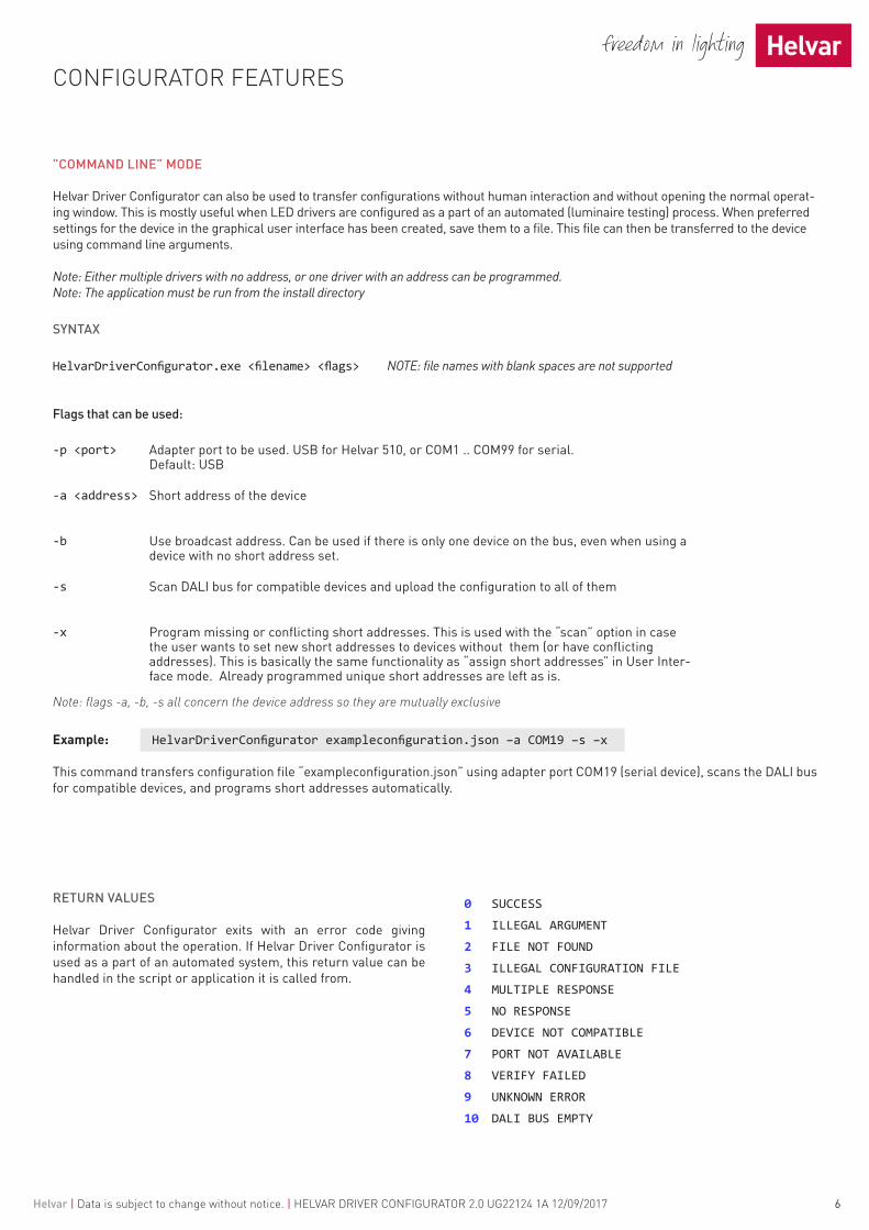
”COMMAND LINE” MODE
Helvar Driver Configurator can also be used to transfer configurations without human interaction and without opening the normal operat-ing window. This is mostly useful when LED drivers are configured as a part of an automated (luminaire testing) process. When preferred settings for the device in the graphical user interface has been created, save them to a file. This file can then be transferred to the device using command line arguments.
Note: Either multiple drivers with no address, or one driver with an address can be programmed.Note: The application must be run from the install directory
SYNTAX
HelvarDriverConfigurator.exe <filename> <flags> NOTE: file names with blank spaces are not supported
Flags that can be used:
-p <port> Adapter port to be used. USB for Helvar 510, or COM1 .. COM99 for serial.Default: USB
-a <address> Short address of the device
-b Use broadcast address. Can be used if there is only one device on the bus, even when using a device with no short address set.
-s Scan DALI bus for compatible devices and upload the configuration to all of them
-x Program missing or conflicting short addresses. This is used with the “scan” option in case the user wants to set new short addresses to devices without them (or have conflicting addresses). This is basically the same functionality as “assign short addresses” in User Inter-face mode. Already programmed unique short addresses are left as is.
Note: flags -a, -b, -s all concern the device address so they are mutually exclusive
Example: HelvarDriverConfigurator exampleconfiguration.json –a COM19 –s –x
This command transfers configuration file “exampleconfiguration.json” using adapter port COM19 (serial device), scans the DALI bus for compatible devices, and programs short addresses automatically.
CONFIGURATOR FEATURES
0 SUCCESS
1 ILLEGAL ARGUMENT
2 FILE NOT FOUND
3 ILLEGAL CONFIGURATION FILE
4 MULTIPLE RESPONSE
5 NO RESPONSE
6 DEVICE NOT COMPATIBLE
7 PORT NOT AVAILABLE
8 VERIFY FAILED
9 UNKNOWN ERROR
10 DALI BUS EMPTY
RETURN VALUES
Helvar Driver Configurator exits with an error code giving information about the operation. If Helvar Driver Configurator is used as a part of an automated system, this return value can be handled in the script or application it is called from.