A Scalable Framework for Monte Carlo Simulation Using …nicola/thesis/phil_masc_2011.pdf · A...
103
A Scalable Framework for Monte Carlo Simulation Using FPGA-based Hardware Accelerators with Application to SPECT Imaging
Transcript of A Scalable Framework for Monte Carlo Simulation Using …nicola/thesis/phil_masc_2011.pdf · A...
A Scalable Framework for Monte Carlo Simulation
Using FPGA-based Hardware Accelerators with
Application to SPECT Imaging

A SCALABLE FRAMEWORK FOR MONTE CARLO
SIMULATION USING FPGA-BASED HARDWARE
ACCELERATORS WITH APPLICATION TO SPECT IMAGING
BY
PHILLIP J. KINSMAN, B.Eng.
a thesis
submitted to the department of electrical & computer engineering
and the school of graduate studies
of mcmaster university
in partial fulfilment of the requirements
for the degree of
Master of Applied Science
c© Copyright by Phillip J. Kinsman, September 2011
All Rights Reserved

Master of Applied Science (2011) McMaster University
(Electrical & Computer Engineering) Hamilton, Ontario, Canada
TITLE: A Scalable Framework for Monte Carlo Simulation Using
FPGA-based Hardware Accelerators with Application to
SPECT Imaging
AUTHOR: Phillip J. Kinsman
B.Eng., (Electrical and Biomedical Engineering)
McMaster University, Hamilton, Ontario
SUPERVISOR: Dr. Nicola Nicolici
NUMBER OF PAGES: xii, 87
ii

Dedicated to my loving wife Alex who reassured unceasingly, despite finding the
contents of this thesis to be quite dry
Abstract
As the number of transistors that are integrated onto a silicon die continues to in-
crease, the compute power is becoming a commodity. This has enabled a whole host
of new applications that rely on high-throughput computations. Recently, the need
for faster and cost-effective applications in form-factor constrained environments has
driven an interest in on-chip acceleration of algorithms based on Monte Carlo simula-
tions. Though Field Programmable Gate Arrays (FPGAs), with hundreds of on-chip
arithmetic units, show significant promise for accelerating these embarrassingly paral-
lel simulations, a challenge exists in sharing access to simulation data amongst many
concurrent experiments. This thesis presents a compute architecture for accelerating
Monte Carlo simulations based on the Network-on-Chip (NoC) paradigm for on-chip
communication. We demonstrate through the complete implementation of a Monte
Carlo-based image reconstruction algorithm for Single-Photon Emission Computed
Tomography (SPECT) imaging that this complex problem can be accelerated by two
orders of magnitude on even a modestly-sized FPGA over a 2GHz Intel Core 2 Duo
Processor. Futhermore, we have created a framework for further increasing paral-
lelism by scaling our architecture across multiple compute devices and by extending
our original design to a multi-FPGA system nearly linear increase in acceleration with
logic resources was achieved.
iv

Acknowledgements
One could hardly put into words the contributions made to this work by the many
wonderful people who surround me on a daily basis. I count myself blessed to have
family, friends and colleagues that support and encourage me and to recognize each
individually would be impossible. Nonetheless, there are some people without whose
explicit mention this thesis would be incomplete. My thanks are extended to the
technical and administrative staff of the Electrical and Computer Engineering de-
partment at McMaster for their patience and aid. I am grateful to Dr. Aleks Jeremic
and Dr. Troy Farncombe for inspiring this project as well as to Dr. Alex Patriciu
and Dr. Shahin Sirouspour for their time and feedback, which have greatly improved
this work.
My warmest gratitude is extended to the many colleagues whose input has been
instrumental in the development of this work. In addition to the classmates who have
seen me through the better part of my education, many hours were contributed to
the refining of this work and myself by Dr. Ehab Anis, Dr. Adam Kinsman, Dr.
Ho Fai Ko, Kaveh Elizeh, Mark Jobes, David Leung, Roomi Sahi and the members
of the Computer Aided Design and Test Laboratory at McMaster: Peter Bergstra,
Zahra Lak, Xiaobing Shi, Pouya Taatizadeh, Jason Thong, and Amin Vali. To my
colleague and eldest brother Dr. Adam Kinsman I extend my deepest thanks. Our
v
many meetings over coffee have inspired, encouraged, and caffeinated the many long
days and nights over the course of my degree. Of those mentioned above, a special
recognition is due Jason and Adam, who along with Nathan Cox spent countless
hours in brainstorming the fundamental insights of this work; I could not have done
it without you. I could never repay the debt I owe to my supervisor, Dr. Nicola
Nicolici. His motivation and mentorship, both personally and professionally, have
been instrumental in this work and my maturation and I count myself far better for
having known him.
In loving memory, I thank Audrey Gleave whose enthusiasm and vitality were a
great example to me. I deeply appreciate my brother-in-law Brandon, sisters-in-law
Pam, Jenn, and Beth, and brothers Adam, Josh, and Matt. I cannot express the
many ways in which my life is better because of you. Our times of recreation have
rejuvenated me and in times of crisis you were an incredible support. My mother-
in-law Susan and grandmother-in-law Shirley are deserving of so much gratitude, as
are my grandparents Lambert and Marie, and my grandmother Julia. Your loving
kindness, letters of encouragement, and many, many hours spent helping me will never
be forgotten. My heartfelt thanks go to my parents Bruce and Jan for their unceasing
enrichment of my life. They have consistently demonstrated the integrity and values
that are critical to good research and their generosity to me is inexhaustible. This
list could only be completed with the addition of my loving wife, Alex. She is the
energy that sustains me, the love that drives me, and the first and last person I think
of each day. Her support and encouragement is written into every page of this work.
Above and before all of these I thank God. He has given me a passion for discovery
and strength for each day and it is only through Him that this work was possible.
vi
Notation and abbreviations
BEE2 Berkeley Emulation Engine IICORDIC Coordinate Rotation Digital ComputerCPU Central Processing UnitCUDA Complete Unified Device ArchitectureDDR Double Data RateDSP Digital Signal ProcessingFLIT Flow UnitFPGA Field Programmable Gate ArrayGNU GNU is Not UNIXGPU Graphics Processing UnitGPGPU General Purpose Graphics Processing UnitLCG Linear Congruential GeneratorLUT Lookup TableLVCMOS Low-Voltage Complementary Metal Oxide SemiconductorMC Monte CarloMSE Mean-Squared ErrorNoC Network on ChipNR Newton-RhapsonPHW Photon History WeightPRNG Pseudo-Random Number GeneratorPU Processing UnitRTL Register Transfer LevelSIMD Single Instruction Multiple DataSM Streaming MultiprocessorSNR Signal to Noise RatioSP Streaming ProcessorSPECT Single Photon Emission Computed TomographyVRT Variance Reduction TechniqueWH Wormhole
vii

Contents
Abstract iv
Acknowledgements v
Notation and abbreviations vii
1 Introduction 1
1.1 Principles of SPECT Imaging . . . . . . . . . . . . . . . . . . . . . . 1
1.2 Simulation Algorithm . . . . . . . . . . . . . . . . . . . . . . . . . . . 2
1.2.1 Scatter Simulation . . . . . . . . . . . . . . . . . . . . . . . . 6
1.2.2 Photon Path Length Sampling . . . . . . . . . . . . . . . . . . 7
1.2.3 Photon Attenuation Calculation . . . . . . . . . . . . . . . . . 7
1.3 Motivation and Contributions . . . . . . . . . . . . . . . . . . . . . . 7
1.4 Organization . . . . . . . . . . . . . . . . . . . . . . . . . . . . . . . 8
1.5 Summary . . . . . . . . . . . . . . . . . . . . . . . . . . . . . . . . . 9
2 Background and Related Work 10
2.1 Platforms for Scientific Computing . . . . . . . . . . . . . . . . . . . 10
2.1.1 Central Processing Units . . . . . . . . . . . . . . . . . . . . . 11
viii
2.1.2 General-Purpose Graphics Processing Units . . . . . . . . . . 12
2.1.3 Field Programmable Gate Arrays . . . . . . . . . . . . . . . . 14
2.2 Literature Survey . . . . . . . . . . . . . . . . . . . . . . . . . . . . . 16
2.3 Network-on-Chip . . . . . . . . . . . . . . . . . . . . . . . . . . . . . 21
2.4 Summary . . . . . . . . . . . . . . . . . . . . . . . . . . . . . . . . . 23
3 Design of a Scalable Framework for Acceleration of SPECT Simula-
tion in Custom Hardware 24
3.1 Computational Trends in the Application . . . . . . . . . . . . . . . . 25
3.2 CPU-based Approach . . . . . . . . . . . . . . . . . . . . . . . . . . . 27
3.3 Queue-based Approach for Massively Multithreading on a GPGPU . 29
3.3.1 Parallel Algorithm . . . . . . . . . . . . . . . . . . . . . . . . 29
3.3.2 Minimizing Divergence . . . . . . . . . . . . . . . . . . . . . . 30
3.3.3 Pseudo-Random Number Generation . . . . . . . . . . . . . . 34
3.3.4 Memory Access . . . . . . . . . . . . . . . . . . . . . . . . . . 36
3.3.5 Photon Queues . . . . . . . . . . . . . . . . . . . . . . . . . . 37
3.3.6 Limitations . . . . . . . . . . . . . . . . . . . . . . . . . . . . 38
3.4 NoC-based Parallel Architecture for FPGAs . . . . . . . . . . . . . . 39
3.4.1 Network Topology and Organization . . . . . . . . . . . . . . 39
3.4.2 Communication Payload and Protocol . . . . . . . . . . . . . 42
3.4.3 Allocation of Communication Resources . . . . . . . . . . . . 44
3.4.4 Routing Policies and Switch Structure . . . . . . . . . . . . . 45
3.4.5 Processing Unit Structure . . . . . . . . . . . . . . . . . . . . 49
3.4.6 Pseudo-Random Number Generator . . . . . . . . . . . . . . . 52
3.5 Scaling the NoC-based Architecture for Increased Parallelism . . . . . 53
ix
3.5.1 Scaling to Multiple FPGAs . . . . . . . . . . . . . . . . . . . 54
3.6 Summary . . . . . . . . . . . . . . . . . . . . . . . . . . . . . . . . . 62
4 Experimental Results 63
4.1 Randomness and Image Quality . . . . . . . . . . . . . . . . . . . . . 64
4.2 Queue-Based GPGPU Implementation . . . . . . . . . . . . . . . . . 66
4.3 NoC-Based FPGA Implementation . . . . . . . . . . . . . . . . . . . 67
4.3.1 Acceleration on a Single FPGA . . . . . . . . . . . . . . . . . 68
4.3.2 Acceleration on Multiple FPGAs . . . . . . . . . . . . . . . . 72
4.4 Summary . . . . . . . . . . . . . . . . . . . . . . . . . . . . . . . . . 76
5 Conclusion and Future Work 77
5.1 Resulting Conclusions . . . . . . . . . . . . . . . . . . . . . . . . . . 77
5.2 Extending the Results to Other Monte Carlo Simulations . . . . . . . 78
x

List of Figures
1.1 Simulation of the Imaging Process . . . . . . . . . . . . . . . . . . . . 2
1.2 Iterative Reconstruction . . . . . . . . . . . . . . . . . . . . . . . . . 3
1.3 Workflow for One Experiment . . . . . . . . . . . . . . . . . . . . . . 4
2.1 Intel Core i7 (Waldock, 2009) . . . . . . . . . . . . . . . . . . . . . . 11
2.2 Thread Grouping in CUDA . . . . . . . . . . . . . . . . . . . . . . . 13
2.3 Logic Block Implementation and Interconnection . . . . . . . . . . . . 15
2.4 Virtex-II Pro Generic Architecture Overview (XILINX, Inc., 2011b) . 16
2.5 Design Flow for FPGA (Kilts, 2007) . . . . . . . . . . . . . . . . . . 17
2.6 Current Approaches to MC Acceleration . . . . . . . . . . . . . . . . 19
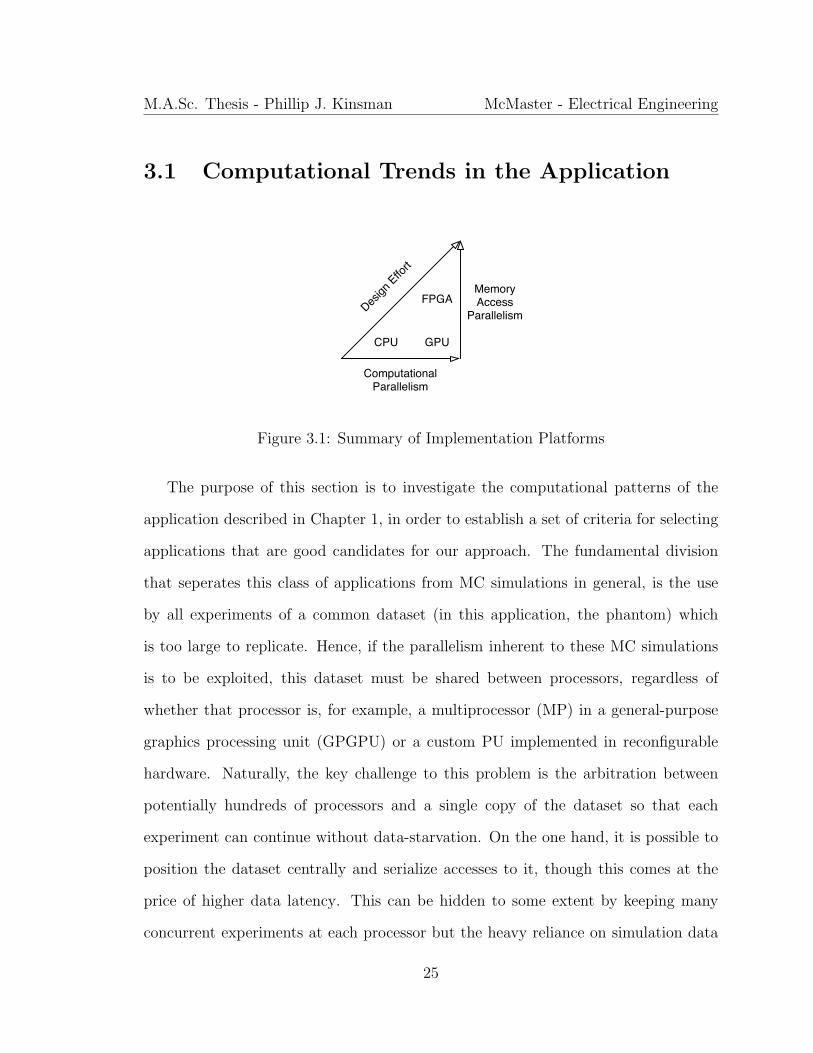
3.1 Summary of Implementation Platforms . . . . . . . . . . . . . . . . . 25
3.2 Flowchart showing different operations . . . . . . . . . . . . . . . . . 30
3.3 Operation of the Photon Queues Within a Block . . . . . . . . . . . . 33
3.4 Hybrid Tausworthe-LCG PRNG . . . . . . . . . . . . . . . . . . . . . 35
3.5 Top Layer of The Network . . . . . . . . . . . . . . . . . . . . . . . . 40
3.6 Experiment Orientation . . . . . . . . . . . . . . . . . . . . . . . . . 41
3.7 Different Types of Network Transfers . . . . . . . . . . . . . . . . . . 43
3.8 Wormhole Switching . . . . . . . . . . . . . . . . . . . . . . . . . . . 47
3.9 Routing Configuration in a Switch . . . . . . . . . . . . . . . . . . . . 48
xi
3.10 Newton-Rhapson Calculator for Processing Units . . . . . . . . . . . 50
3.11 Shift-Structure Implementation of Tausworthe PRNG . . . . . . . . . 53
3.12 Two Connections Statically Combined to One Virtual Channel . . . . 58
3.13 Four Connections Dynamically Combined to Two Virtual Channels . 61
4.1 Image SNR vs. Simulation Size . . . . . . . . . . . . . . . . . . . . . 67
4.2 Sample Reconstructed Image . . . . . . . . . . . . . . . . . . . . . . . 68
4.3 Inter-chip Communication on the BEE2 . . . . . . . . . . . . . . . . 69
xii
Chapter 1
Introduction
Single Photon Emission Computed Tomography (SPECT) is a medical imaging modal-
ity used clinically in a number of diagnostic applications, including detection of car-
diac pathology, various forms of cancer, and certain degenerative brain diseases. Con-
sequently, timely and accurate reconstruction of SPECT images is of critical impor-
tance. This chapter describes this imaging modality in Section 1.1 and outlines the
SPECT simulation algorithm considered by this work in Section 1.2. Section 1.3
goes on to motivate and summarize the principle contributions of this work. Finally,
Section 1.4 outlines the organization of the rest of the document.
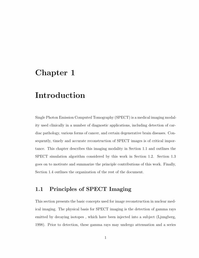
1.1 Principles of SPECT Imaging
This section presents the basic concepts used for image reconstruction in nuclear med-
ical imaging. The physical basis for SPECT imaging is the detection of gamma rays
emitted by decaying isotopes , which have been injected into a subject (Ljungberg,
1998). Prior to detection, these gamma rays may undergo attenuation and a series
1

M.A.Sc. Thesis - Phillip J. Kinsman McMaster - Electrical Engineering
of scatterings on their course of exit from the patient. This makes determination of
the variable of interest - namely the distribution of the radioactive source within the
patient - nontrivial. As previously mentioned, the focus of this work is the accelerated
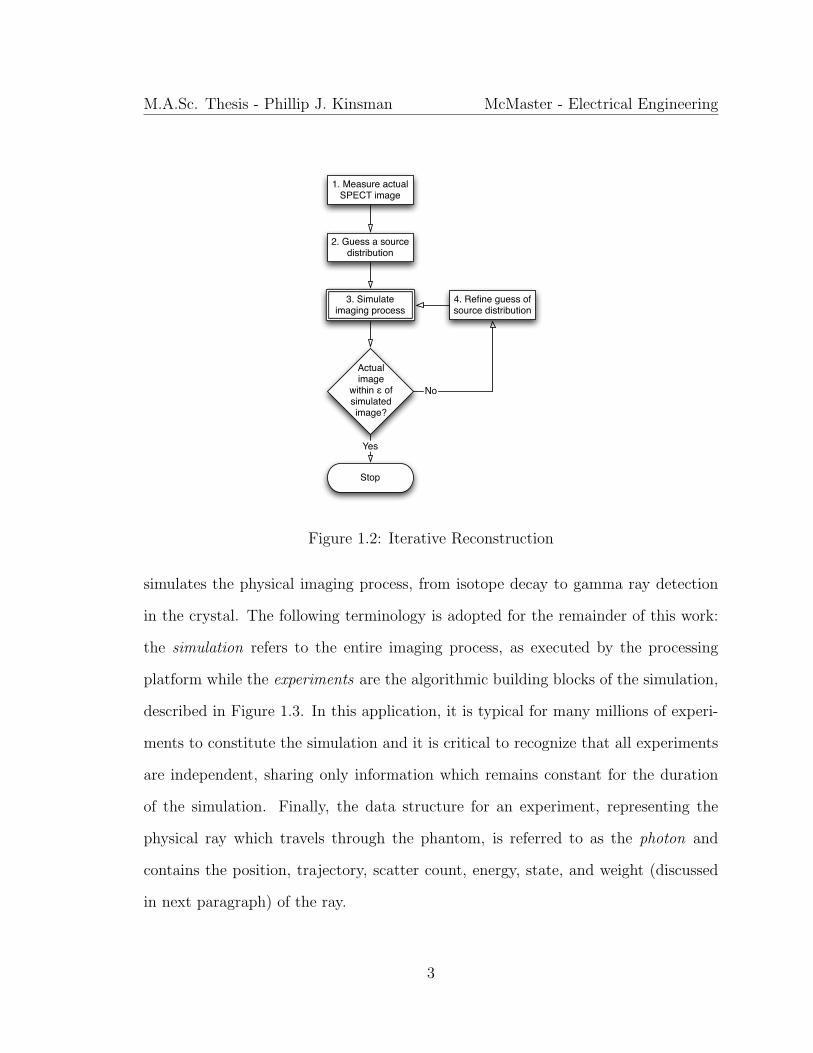
simulation of this imaging process (see Figure 1.1) using Monte Carlo methods, since
this simulation is in the inner loop of a group of iterative reconstruction algorithms
depicted in Figure 1.2. It should be noted that the actual iterative refinement for
image reconstruction is not addressed explicitly by this work.
Scatter Model
Monte Carlo
Simulation
Patient DensityScan (3D)
Source Distribution (3D)
SimulatedImage (2D)
Figure 1.1: Simulation of the Imaging Process
1.2 Simulation Algorithm
As a model for the simulation depicted in Figure 1.1, we adopted the SIMIND Monte
Carlo application (Ljungberg, 1998) developed by Michael Ljungnberg at Lunds Uni-
versitet. This FORTRAN software model takes a description of the source distribution
and a density map of the imaged subject (henceforth referred to as the phantom) and
2
M.A.Sc. Thesis - Phillip J. Kinsman McMaster - Electrical Engineering
2. Guess a source distribution
3. Simulate imaging process
Actual image
within ε of simulated image?
1. Measure actual SPECT image
4. Refine guess of source distribution
No
Stop
Yes
Figure 1.2: Iterative Reconstruction
simulates the physical imaging process, from isotope decay to gamma ray detection
in the crystal. The following terminology is adopted for the remainder of this work:
the simulation refers to the entire imaging process, as executed by the processing
platform while the experiments are the algorithmic building blocks of the simulation,
described in Figure 1.3. In this application, it is typical for many millions of experi-
ments to constitute the simulation and it is critical to recognize that all experiments
are independent, sharing only information which remains constant for the duration
of the simulation. Finally, the data structure for an experiment, representing the
physical ray which travels through the phantom, is referred to as the photon and
contains the position, trajectory, scatter count, energy, state, and weight (discussed
in next paragraph) of the ray.
3
M.A.Sc. Thesis - Phillip J. Kinsman McMaster - Electrical Engineering
PrimaryPhoton?
Sample Isotropic Direction
no
Calculate Attenuation to Detector
Update History Weight
Simulate Detection
Return
Compute Direction Cosines
Compute Dmax
Sample photon path ( < Dmax)
Calculate Interaction coordinates
Update History Weight
Scatter Order < max?
Sample Coherent Scattering
Sample Compton Scattering
SampleScatterType
y
EntrySample
max scatter order
yes
Compton Scattering
Photon direction in solid angle
Figure 1.3: Workflow for One Experiment
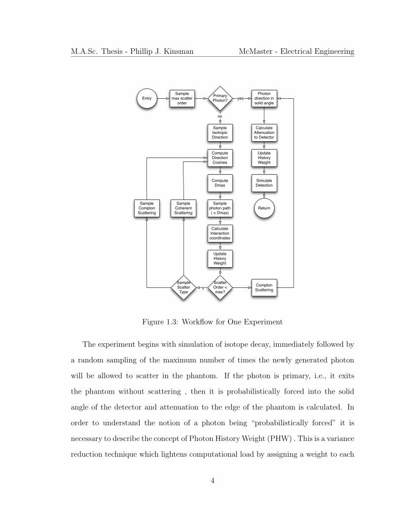
The experiment begins with simulation of isotope decay, immediately followed by
a random sampling of the maximum number of times the newly generated photon
will be allowed to scatter in the phantom. If the photon is primary, i.e., it exits
the phantom without scattering , then it is probabilistically forced into the solid
angle of the detector and attenuation to the edge of the phantom is calculated. In
order to understand the notion of a photon being “probabilistically forced” it is
necessary to describe the concept of Photon History Weight (PHW) . This is a variance
reduction technique which lightens computational load by assigning a weight to each
4

M.A.Sc. Thesis - Phillip J. Kinsman McMaster - Electrical Engineering
photon as it is emitted. This weight is reduced in proportion to the probability
of each photon interaction over the course of the experiment . Consequently, some
information is contributed to the final image by every experiment. This is in contrast
to the traditional approach where photons are probabilistically eliminated at each
interaction with only the surviving photons contributing to the resultant image. It
is worth noting that the initial value of the weight is the same for each experiment
and represents the average decay activity per photon as calculated by Equation 1.1,
where n is the number of photons emitted per decay, γ is the activity of the source
in Bq, and N is the total number of photon histories to be simulated.
W0 = γn
N(1.1)
Though several variance reduction techniques are commonly employed to decrease
run-time, (Liu et al., 2008; Beekman et al., 2002; de Wit et al., 2005), above we have
summarized one representative example.
If the photon is not a primary photon, then an emission trajectory is randomly
sampled and its corresponding direction cosines are computed. Next, the maximum
distance to the next interaction site (Dmax) is computed and then a photon path
length is sampled (less than Dmax). If the scatter order of the photon is less than
the previously sampled maximum, then a scatter type is sampled, the interaction is
simulated, and the loop repeats. Otherwise, a Compton scattering is forced in order
to direct the photon into the solid angle of the detector and the photon attenuation
and detection are simulated as with primary photons.
The reader can obtain more detailed information regarding the specific implemen-
tation details from (Ljungberg, 1998) or on the SIMIND website (Ljungberg, 2010).
5
M.A.Sc. Thesis - Phillip J. Kinsman McMaster - Electrical Engineering
The focus of this work is primarily on the development of a framework enabling the
mapping of this algorithm onto a new implementation platform that can better lever-
age its inherent parallelism through the implementation of many processing units.
Therefore, specific algorithmic details are discussed in the following paragraphs only
as they provide insight into the design considerations for this framework.
1.2.1 Scatter Simulation
At the site of an interaction in the phantom, one of two types of scatter can occur:
Compton or Rayleigh (coherent). Compton scattering is a physical process whereby
an X-ray or γ-ray scatters inelastically, resulting in a change in direction and increase
in wavelength, (Busberg et al., 2001). The energy lost by the ray is used to eject
a scattering electron from an atom in the scatter medium. This ionizes the atom,
hence the term ionizing radiation attributed to such high-energy photons. On the
other hand, Rayleigh scattering is a type of elastic scattering that can occur with
much lower energy radiation, even visible light. In this case, a direction change is
observed, while the photon energy remains the same, (Busberg et al., 2001). Random
sampling dictates which of the two types of scatter occurs but both use a sample-
reject method that requires up to hundreds of accesses to a scatter model. The
substantial amount of data represented in these models and the high frequency with
which they are accessed have important computational side effects, to be elaborated
later in Section 3.4.5.
6

M.A.Sc. Thesis - Phillip J. Kinsman McMaster - Electrical Engineering
1.2.2 Photon Path Length Sampling
As mentioned above, when a photon is not primary, it is necessary to sample the
location of the next photon interaction site. The site is determined by a combination
of random sampling and comparison with density values along the photon’s trajectory.
In the vast majority of cases this can be accomplished by sampling only 1-3 values from
the density map, keeping in mind that these values often lay far from the photon’s
current position in the phantom. The implications of this become clear in Section
3.4.2 when the patterns of on-chip data transfers are discussed.
1.2.3 Photon Attenuation Calculation
As a photon exits the phantom , it experiences attenuation proportional to the integral
of the density values along the exit path. This process is necessarily discretized, such
that the photon takes small steps along the exit trajectory and reads the density at
each point and in so doing, incrementally calculates the total attenuation . In the
majority of cases, this process requires 20-100 samples from the density map, though
each sample exhibits high spatial locality to its preceding and following samples. The
relevance of this matter is, again, further elaborated in Section 3.4.2.
1.3 Motivation and Contributions
As elluded to in the previous section, the massive simulations used for image recon-
struction are extremely computationally demanding. As a result, current practices
struggle to achieve clinically acceptable run-times (on the order of hours) without
7

M.A.Sc. Thesis - Phillip J. Kinsman McMaster - Electrical Engineering
compromising image quality, delaying time-critical diagnosis and treatment of pa-
tients. The primary contribution of this work is to address this problem through the
creation of a scalable framework for the design of a custom hardware accelerator for
this application. The efficacy of our approach is validated through the implementa-
tion of a parallel on-chip architecture for the algorithm described in Section 1.2, which
achieves two orders of magnitude acceleration over an optimized single-core software
implementation. The massive parallelism facilitated by the efficient use of all of the
large number of processing units that were implemented is enabled by the design of
on-chip networks for their interconnection. In order to justify the relatively large de-
sign effort for the custom hardware implementation of this application, our approach
is compared to another state-of-the-art platform for massively parallel computing. Fi-
nally, a methodology is developed for scaling the design to multiple compute devices
with a near-linear relationship between logic resources and acceleration.
1.4 Organization
Having described the physical basis and application for this work, Chapter 2 de-
scribes the processing platforms considered for this application and surveys the cur-
rent knowledge in this field in order to position the uniqueness of our contribution.
This is followed by a chapter describing our new framework and giving details of the
complete implementation of the SPECT simulation application in custom hardware
. Next, Chapter 4 demonstrates the efficacy of our approach by comparing our im-
plementation to optimized instances of the application on two other state-of-the-art
platforms. Finally, Chapter 5 outlines the implications of this work for the broad
scope of applications with similar underlying algorithmic patterns.
8

M.A.Sc. Thesis - Phillip J. Kinsman McMaster - Electrical Engineering
1.5 Summary
This chapter has introduced SPECT imaging as the focal problem of this thesis. The
algorithm of the SPECT simulator taken as a model for our development was de-
scribed and its key deficiency was highlighted in order to motivate this work. Finally,
our key contributions were summarized and this document’s organization was out-
lined. The next chapter goes on to give background for the compute devices leveraged
in scientific computing as well as to survey the current art in computation for SPECT
simulation.
9

Chapter 2
Background and Related Work
Having described SPECT imaging and the motivation for this work in the previous
chapter, the purpose of this chapter is to provide background knowledge in modern
computational platforms as well as to survey the current literature from the field of
SPECT simulation. Furthermore, the design methodologies relevant to this work are
introduced at a conceptual level.
2.1 Platforms for Scientific Computing
This section details the compute platforms which currently represent the standard
options for scientific computing applications. Each is described structurally and cur-
rent design practices are highlighted with a focus on their relative strengths and
weaknesses.
10
M.A.Sc. Thesis - Phillip J. Kinsman McMaster - Electrical Engineering
2.1.1 Central Processing Units
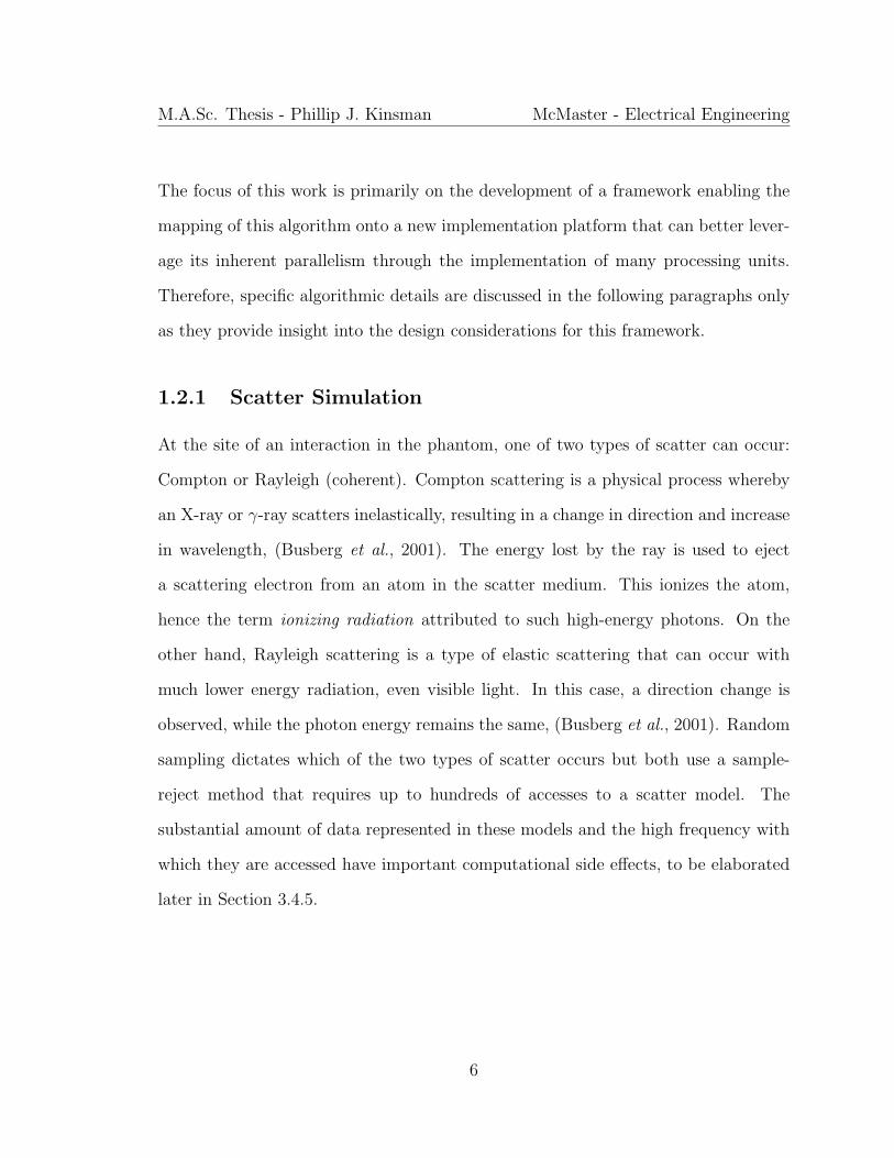
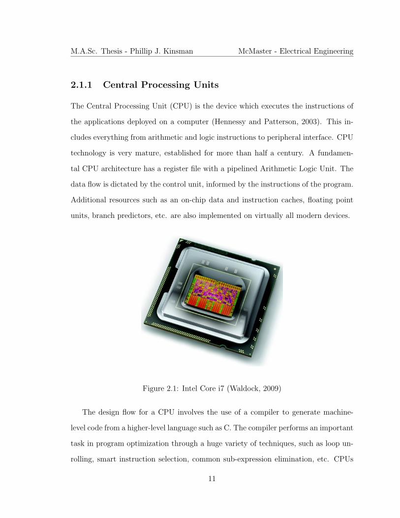
The Central Processing Unit (CPU) is the device which executes the instructions of
the applications deployed on a computer (Hennessy and Patterson, 2003). This in-
cludes everything from arithmetic and logic instructions to peripheral interface. CPU
technology is very mature, established for more than half a century. A fundamen-
tal CPU architecture has a register file with a pipelined Arithmetic Logic Unit. The
data flow is dictated by the control unit, informed by the instructions of the program.
Additional resources such as an on-chip data and instruction caches, floating point
units, branch predictors, etc. are also implemented on virtually all modern devices.
Figure 2.1: Intel Core i7 (Waldock, 2009)
The design flow for a CPU involves the use of a compiler to generate machine-
level code from a higher-level language such as C. The compiler performs an important
task in program optimization through a huge variety of techniques, such as loop un-
rolling, smart instruction selection, common sub-expression elimination, etc. CPUs
11

M.A.Sc. Thesis - Phillip J. Kinsman McMaster - Electrical Engineering
further improve executable performance through instruction-level optimization and
high operational frequencies, possible through deep pipelining. However, as sequen-
tial processors, they suffer from an inability to exploit application-level parallelism,
making them very effective for control-intensive applications but leaving room for
improvement in the highly parallel data-flow applications typical in scientific com-
puting.
In the 1980s, the transputer was pioneered as one attempt to try and overcome
these challenges (Arabnia, 1998). This was a highly integrated processor with serial
communication links intended for parallel processing. Multiple transputers could be
networked together and special directives were provided for programmers to split a
program’s workload across the devices. Although this technology did not ultimately
become central to modern parallel computing, its architecture did provide ideas which
have emerged in different forms in this field.
2.1.2 General-Purpose Graphics Processing Units
A Graphics Processing Unit (GPU) is a compute device present in almost all per-
sonal computers that is essentially designed to process large blocks of data in parallel.
This makes it highly effective at graphics computation but recent interest in leverag-
ing these specialized processing resources for general purpose computation has given
birth to frameworks developed especially for mapping parallel applications to GPU
devices. One such framework is the Complete Unified Device Architecture (NVIDIA
Corporation, 2011). CUDA uses a Single Instruction Multiple Data (SIMD) execution
model where threads are grouped into bundles of 32, called warps, and each instruc-
tion is executed simultaneously on all the threads in a warp. Warps are grouped
12
M.A.Sc. Thesis - Phillip J. Kinsman McMaster - Electrical Engineering
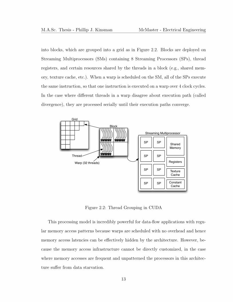
into blocks, which are grouped into a grid as in Figure 2.2. Blocks are deployed on
Streaming Multiprocessors (SMs) containing 8 Streaming Processors (SPs), thread
registers, and certain resources shared by the threads in a block (e.g., shared mem-
ory, texture cache, etc.). When a warp is scheduled on the SM, all of the SPs execute
the same instruction, so that one instruction is executed on a warp over 4 clock cycles.
In the case where different threads in a warp disagree about execution path (called
divergence), they are processed serially until their execution paths converge.
Grid
Block
Thread
Warp (32 threads)
Shared Memory
SP SP
SP SP
SP SP
SP SP
Registers
Texture Cache
Constant Cache
Streaming Multiprocessor
Figure 2.2: Thread Grouping in CUDA
This processing model is incredibly powerful for data-flow applications with regu-
lar memory access patterns because warps are scheduled with no overhead and hence
memory access latencies can be effectively hidden by the architecture. However, be-
cause the memory access infrastructure cannot be directly customized, in the case
where memory accesses are frequent and unpatterned the processors in this architec-
ture suffer from data starvation.
13
M.A.Sc. Thesis - Phillip J. Kinsman McMaster - Electrical Engineering
2.1.3 Field Programmable Gate Arrays
Field Programmable Gate Arrays (FPGAs) are compute devices containing logic
which is programmable in both its function and interconnection (Kilts, 2007). As
such they enable the implementation of custom hardware architectures for applica-
tions that cannot be fully optimized onto traditional compute devices. The funda-
mental logic element of an FPGA is a Look-up Table (LUT), capable of computing
any logic function because the inputs to the LUT form the selection lines of a mul-
tiplexer whose data inputs are set at configuration-time. Most modern FPGAs are
coarse-grained, meaning that they group one or more LUTs together with additional
logic and one or more registers to form a logic block. A representative example of
such a logic block is shown in Figure 2.3a, where configurable cells are denoted by
P, and detailed schematics for modern devices are given in XILINX, Inc. (2009) and
Altera Corporation (2011).
Modern devices typically also contain more sophisticated logic blocks such as
digital signal processing units, embedded memories, and even microprocessor cores. A
full architecture of the device used in this work is shown in Figure 2.4. The logic blocks
on the FPGA die are interconnected by the routing fabric, conceptually demonstrated
by Figure 2.3b. The actual implementation of the programmable connections between
routing tracks varies between devices and may make use of different technologies such
as pass transistors, floating-gate transistors, multiplexers, etc. However, in all cases
FPGA designers try to allocate only enough routing resources to route most designs
successfully in order to avoid over-allocating and wasting on-chip logic and device
power consumption.
14

M.A.Sc. Thesis - Phillip J. Kinsman McMaster - Electrical Engineering
PPPPPPPP
PPPPPPPP
+cin
cout
DQ
>
PP
(a) Logic Block (b) Logic Interconnection
Logic Block
Logic Block
Logic Block
Logic Block
Logic Block
Logic Block
Logic Block
Logic Block
Logic Block
RouteMatrix
RouteMatrix
RouteMatrix
RouteMatrix
Figure 2.3: Logic Block Implementation and Interconnection
The design flow for FPGAs is depicted in Figure 2.5. Hardware designs are spec-
ified in Register Transfer Level (RTL) code, which abstracts the gate-level imple-
mentation of logic functions. Sophisticated tool-chains are responsible for synthesis
and place-and-routing the design but the key insight from this diagram is the itera-
tive nature of FPGA design. This indicates one of the significant challenges to the
creation of a custom hardware architecture for an application. Although for many
applictions, substantial acceleration can be achieved through the ability to tailor pro-
cessing resources and data-flow patterns to an application, this comes at the price of
significantly more skilled design labour than for an optimized software design. Hence,
FPGAs are only appropriate for applications either where real-time constraints can-
not be met by traditional compute platforms or substantial benefit can be realized
through additional acceleration or energy optimization.
15

M.A.Sc. Thesis - Phillip J. Kinsman McMaster - Electrical Engineering
Figure 2.4: Virtex-II Pro Generic Architecture Overview (XILINX, Inc., 2011b)
2.2 Literature Survey
Although computationally efficient analytical solutions do exist for the problem of
SPECT image reconstruction introduced in Chapter 1, they are highly susceptible to
noise (Kao and Pan, 1998). Since image quality has direct implications to patient
care, statistical reconstruction methods are typically favoured despite their relatively
long runtimes (Beekman et al., 2002; Hutton et al., 1997). The last decade has seen
the development of numerous variance reduction techniques (VRTs) (Liu et al., 2008;
Beekman et al., 2002; de Wit et al., 2005), which accelerate these statistical recon-
struction methods by optimizing the algorithms of the Monte Carlo (MC) simulations
at their core. These have been quite successful in bringing image reconstruction time
16

M.A.Sc. Thesis - Phillip J. Kinsman McMaster - Electrical Engineering
Specification/Architecture
RTL Design and
Optimization
RTL Simulation
Synthesis Synthesis Optimization
Place and Route
Place and Route
Optimization
Static Timing and
Performance Analysis
Program and Debug Device
Figure 2.5: Design Flow for FPGA (Kilts, 2007)
into a reasonable range for relatively small images. For example, the work from
(Beekman et al., 2002) demonstrates the reconstruction of a 64x64x64 image on a
dual core processor in approximately half an hour. However, because of the underly-
ing structure of MC simulations, we propose that by investigating solutions in parallel
computing, images of higher resolution can be reconstructed without paying a very
costly time premium. Naturally, such a parallel solution could also exploit these
VRTs.
That MC simulations are good candidates for parallelization is quite intuitive,
17

M.A.Sc. Thesis - Phillip J. Kinsman McMaster - Electrical Engineering
as fundamentally they are comprised of huge numbers of independant experiments.
This is, in fact, confirmed by the authors of (Dewaraja et al., 2000), wherein they
demonstrate that nearly linear speedup in the number of processors can be achieved
for this application. Although they demonstrate a 32x speedup with a computing grid,
this approach quickly becomes prohibitively expensive in terms of compute resources
and energy consumption and suffers form-factor requirements that are undesirable for
a clinical setting. This is indeed the motivation for pursuing acceleration on massively
parallel, yet integrated, platforms in reduced form factors.
There exists already a large body of work in accelerating MC simulations on both
field-programmable gate arrays (FPGAs) (Fanti et al., 2009; Kaganov et al., 2008;
Pasciak and Ford, 2006; Tian and Benkrid, 2009, 2008; Woods and VanCourt, 2008;
Yamaguchi et al., 2003; Luu et al., 2009) and graphics processing units (GPUs) (Badal
and Badano, 2009; Gulati and Khatri, 2009; Jiang et al., 2009; Wirth et al., 2009; Xu
et al., 2010; Zhao and Zhou, 2010). A graphical depiction of the relationship of these
works is given in Figure 2.6. Though other examples of accelerating MC simulations
through cluster computing do exist, (Dewaraja et al., 2000) was chosen because it
considers the same application discussed here. Interestingly, though the specific case
studies are distinct, two of the GPU implementations (Badal and Badano, 2009;
Wirth et al., 2009) are algorithmically similar to the application presented here. In
both cases, the results presented are somewhat modest in comparison to the number
of cores when contrasted with the results presented in Section 4 of this work. In
order to understand the reason for this, it is necessary to investigate the application
in further depth. This application falls into a class of Monte Carlo simulations in
which all the experiments share data from a common dataset which is sufficiently
18

M.A.Sc. Thesis - Phillip J. Kinsman McMaster - Electrical Engineering
large to prohibit complete reproduction for each processing node. Furthermore, in
such experiments, the data access patterns are not known a priori. Other examples
from this class include weather, environmental, and risk evaluation simulations and
are discussed further in Chapter 5.
CLUSTER
FPGAGPU VRT
SingleCore
MultiCore
8
332
1113
35
37
4
718
9
21
2514
30
31
33
36
ThisWork
Shared Dataset
No Shared Dataset
Figure 2.6: Current Approaches to MC Acceleration
GPUs are known to provide substantial acceleration benefits to arithmetically in-
tense algorithms that have structured data accesses and limited branching (Pharr,
2005; Kirk and mei W. Hwu, 2010). Therefore, as suggested by the authors of (Badal
and Badano, 2009) and (Wirth et al., 2009), GPU implementations of this kind of sim-
ulation suffer from the frequency and randomness with which individual experiments
retrieve data from memory. In contrast, the increased development effort for FPGAs
repays the designer with complete flexibility in how memory is distributed amongst
the processing engines. This, in combination with the ability to craft application-
specific on-chip communication architectures, suggests FPGAs as the best platform
19
M.A.Sc. Thesis - Phillip J. Kinsman McMaster - Electrical Engineering
for developing a scalable framework for running hundreds of concurrent experiments
without data starvation. It is at this point, then, that we revisit the previously
mentioned FPGA-based attempts at parallelizing Monte Carlo simulations. Of these,
most do not fall into the category of shared dataset Monte Carlo and are consequently
able to be parallelized with no consideration given to inter-experiment communication
(Tian and Benkrid, 2009; Yamaguchi et al., 2003; Tian and Benkrid, 2008; Kaganov
et al., 2008; Woods and VanCourt, 2008). However, the remaining works merit a
more in-depth treatment as they share fundamental algorithmic similarities to the
application discussed here.
One of the earliest works to consider the use of FPGAs to accelerate Monte Carlo
simulations implemented a simplified version of the radiation transport problem (Pas-
ciak and Ford, 2006). In this case, the authors worked with a single point source in an
“infinite medium of aluminum”. Naturally, this completely circumvented the issue of
storing a density map and consequently, this work should not be categorized with the
large shared data-set simulations considered here. The authors of (Fanti et al., 2009)
consider a Monte Carlo simulation for dose calculation in radiotherapy treatment.
They address the issue of the large simulation dataset by taking a pipelining rather
than a multi-core approach to acceleration. They implemented a single-core pipelined
solution but the technical details from the paper suggest that limited acceleration can
be achieved. The work presented in (Luu et al., 2009) also approaches acceleration
through pipelining instead of parallelization. This paper clearly details an insightful
and well-executed implementation and the results are very promising. However, their
design methodology is application-specific. In contrast, our work presents a modular
approach that can be reused in other application domains to ease the design effort.
20
M.A.Sc. Thesis - Phillip J. Kinsman McMaster - Electrical Engineering
Furthermore, the architecture presented in (Luu et al., 2009) is not designed with a
focus on scalability, while our approach enables the parameterized adjustment of the
design size with results suggesting near-linear scaling of compute speed.
Having justified a multi-core approach to accelerating the application, the key
problem to be addressed is how to arbitrate access to the large shared dataset by
possibly hundreds of processing units (PUs). The random nature of the experiments
suggests the need for a flexible architecture that allows run-time configuration of the
data transfers. Furthermore, when considering the more general applicability of this
work to many instances of Monte Carlo simulations, it is highly desirable to create
a solution that will scale easily to adapt to different problem sizes. Consequently,
we adopted the Network-on-Chip design paradigm (de Micheli and Benini, 2006),
introduced in the next section, to fully implement and verify a 128 processing unit
network that accelerated the MC simulation central to SPECT imaging. We are not
aware of any other works that have adopted an NoC approach to accelerating Monte
Carlo simulations.
2.3 Network-on-Chip
Network-on-Chip (NoC) is a design paradigm for System-on-Chip (SoC) that ad-
dresses the design of the communication infrastructure between processing cores
(de Micheli and Benini, 2006). It leverages knowledge from networking theory to
improve the scalability and power efficiency of complex SoCs over traditional bus
implementations. NoC designs establish a communication fabric, called the network,
which exchanges data between different modules such as processors, memories and
other IP blocks. A design created with the NoC paradigm can offer a high degree of
21
M.A.Sc. Thesis - Phillip J. Kinsman McMaster - Electrical Engineering
parallelism because the links in the NoC can operate simultaneously on different data
packets. Furthermore, the regular structure of the network gives more predictability
to the speed and reliability of on-chip signalling, hence easing the design process.
In designing a NoC, the key questions which must be answered are the topology,
routing, and switching policies. Topology refers to the layout pattern of the inter-
connection of modules. Though certain topologies are commonly employed, such as
mesh or torus, there is growing research in application-specific NoC topology synthe-
sis (Marculescu et al., 2009). Routing refers to the selection of a path for a packet
to take through the network. Though there are no theoretical restrictions on the
routing technique selected, the highly integrated nature of NoCs tends to practically
limit them to rely on simpler routing techniques, such as one-turn routing and virtual-
channel based routing (de Micheli and Benini, 2006). Finally, switching refers to the
interconnection of network segments and is responsible for directing packets at each
step in order to implement the selected routing scheme. As with routing, this is an
extremely active area of research (Marculescu et al., 2009), though in applications of
extremely high parallelism, resource usage tends to be the overwhelming constraint
in selecting a switching technique.
One of the most significant benefits of NoCs from a hardware design standpoint is
that they facilitate the scaling of homogeneous designs. In the case where an applica-
tion can be mapped in a systematic way onto a parameterizable number of processors,
NoCs provide the mechanism for a similarly parameterizable interconnection of these
processors. This is particularly important for designs targeted to FPGAs because it
can allow designs to port smoothly to new devices as they are brought to market.
22
M.A.Sc. Thesis - Phillip J. Kinsman McMaster - Electrical Engineering
2.4 Summary
This chapter has provided the necessary background into computation platforms,
specifically as they relate to this work. Furthermore, it summarized the current
literature in the field of SPECT simulation in order to highlight the uniqueness and
necessity of our work as well as introducing fundamental principles of the NoC design
methodology. With this background information relayed, the next chapter goes on to
describe our new framework for the design of custom hardware accelerators for this
application.
23

Chapter 3
Design of a Scalable Framework for
Acceleration of SPECT Simulation
in Custom Hardware
In this chapter, we detail our approach for accelerating the Monte Carlo (MC) simu-
lations at the core of SPECT image reconstruction (introduced in Chapter 1) through
an on-chip network of processing units (PU) in custom hardware. In Section 3.1 the
computational patterns that define the class of MC simulations to which our approach
applies are discussed. Then, Sections 3.2 and 3.3 report on the implementation of a
software-based approach for single-threaded and massively multi-threaded platforms
respectively. This is done to justify the need for our approach in custom hardware,
subsequently described in Section 3.4, with a discussion of design scalability given in
Section 3.5.
24
M.A.Sc. Thesis - Phillip J. Kinsman McMaster - Electrical Engineering
3.1 Computational Trends in the Application
Design
Effort
ComputationalParallelism
MemoryAccess
Parallelism
CPU GPU
FPGA
Figure 3.1: Summary of Implementation Platforms
The purpose of this section is to investigate the computational patterns of the
application described in Chapter 1, in order to establish a set of criteria for selecting
applications that are good candidates for our approach. The fundamental division
that seperates this class of applications from MC simulations in general, is the use
by all experiments of a common dataset (in this application, the phantom) which
is too large to replicate. Hence, if the parallelism inherent to these MC simulations
is to be exploited, this dataset must be shared between processors, regardless of
whether that processor is, for example, a multiprocessor (MP) in a general-purpose
graphics processing unit (GPGPU) or a custom PU implemented in reconfigurable
hardware. Naturally, the key challenge to this problem is the arbitration between
potentially hundreds of processors and a single copy of the dataset so that each
experiment can continue without data-starvation. On the one hand, it is possible to
position the dataset centrally and serialize accesses to it, though this comes at the
price of higher data latency. This can be hidden to some extent by keeping many
concurrent experiments at each processor but the heavy reliance on simulation data
25
M.A.Sc. Thesis - Phillip J. Kinsman McMaster - Electrical Engineering
exhibited by this application could make the cost of such frequent context-switching
prohibitive. This approach is demonstrated on GPGPU in Section 3.3 in order to
verify that it does not distribute data effectively as the number of processors is scaled.
Conversely, the problem can be addressed by distributing the dataset amongst the
processors and providing a mechanism for communication between the processors
such that each experiment can relocate itself to the processor containing the data it
needs. This approach represents the fundamental contribution of this work and is
investigated in Section 3.4 on custom hardware because of the ability to customize
on-chip communication.The relationship between these platforms is summarized in
Figure 3.1.
Futher characterization of these shared dataset MC simulations was possible by
profiling the SIMIND Monte Carlo software. By developing an insight into the pat-
terns that underlie this application, we established three more criteria that apply to
the broad spectrum of problems which fall into this application class:
1. the ratio of shared dataset accesses to arithmetic operations is very high (in
this case, approximately 1:1)
2. an experiment may access data from spatially distant points of the density map
over its entire duration, however, the majority of data accesses in close temporal
proximity also exhibit close spatial proximity
3. the majority of simulation time is spent in sampling, with only a small amount
spent on complex arithmetic and trigonometric processing
The design decisions detailed below are made in a way that directly exploits
the above computational patterns. Naturally, applications that deviate heavily from
26
M.A.Sc. Thesis - Phillip J. Kinsman McMaster - Electrical Engineering
these patterns will fail to realize significant benefit from the methodology proposed
here. Though the implementation work necessary to empirically substantiate through
implementation the applicability of this approach to other applications is outside the
scope of this work, a brief survey of applications of MC simulations reveals a number
of algorithms that bear strong similarities to the candidate for this case study. This
is discussed further in Chapter 5.
3.2 CPU-based Approach
The SIMIND Monte Carlo simulation software taken as a model for this application
showed significant room for improvement. Consequently, the 14,000 lines of FOR-
TRAN source were redeveloped in C which enabled the restructuring of the program
to enable easy extraction of profiling and debug data so that a thorough understand-
ing of the computational patterns could be achieved. Futhermore, the redevelopment
was done with an intent focus on performance and compute efficiency so that we
would have a reasonable reference to which to compare our hardware design. This
section outlines the most significant optimizations that were leveraged in the software
model to accelerate computation and, where appropriate, describes specific changes
from the original software to the redesigned software.
As was introduced in Section 1.2, SIMIND leverages a number of Variance Re-
duction Techniques (VRT) to improve simulation time. The first such VRT used is
the notion of Photon History Weight (PHW), where a photon’s relative contribution
to the final image is adjusted based on the events in its history, described in detail in
Section 1.2. The simulation also employs the well-established Forced Detection VRT.
This is a technique in which the direction of travel of all photons is forced in the
27

M.A.Sc. Thesis - Phillip J. Kinsman McMaster - Electrical Engineering
direction of the detector surface as they exit the object under study. This increases
the probability of photon detection such that a higher percentage of photon histories
contribute to the final image. The final significant VRT used by SIMIND is the con-
cept of multiple detection. In this case, detection is simulated multiple times at each
photon interaction. That is, each portion of the photon history contributes to multi-
ple locations in the final image, allowing the reuse of each experiment’s computation
multiple times.
In addition to these VRTs, multiple algorithmic techinques were used to accelerate
the MC simulation. Unnecessary branching was eliminated and loops were rewritten
in a way that enabled optimization by the compiler. Furthermore, because a photon
typically travels to multiple locations without changing direction, its current trajec-
tory is stored as a set of direction cosines. In this way, the cosines are computed once
per direction change and position updating is done through adding a factor of these
cosines to the current position (with the understanding that multiplication is less ex-
pensive than the trigonometric functions required for computing direction changes).
New algorithms were implemented for the searching of cross-section tables that is
required by scatter simulation. The regularity often exhibited by these profiles is
established in pre-simulation and used to accelerate the searching which happens nu-
merous times in each experiment. Finally, attempts in the original software to cache
certain values used in the simulation were eliminated, as they seemed to actually
hinder performance.
This process resulted in an implementation that generated identical images to the
original FORTRAN but was already several times faster and it should be noted that
it is this C implementation against which all results in Chapter 4 are reported.
28

M.A.Sc. Thesis - Phillip J. Kinsman McMaster - Electrical Engineering
3.3 Queue-based Approach for Massively Multi-
threading on a GPGPU
This section describes our implementation of the application on a massively multi-
threaded processor using the Complete Unified Device Architecture (CUDA) frame-
work described in Section 2.1.2.
3.3.1 Parallel Algorithm
Because of the natural divisions in the simulation, the approach taken to parallelisa-
tion is to assign independent experiments to different threads. The flowchart shown
in Figure 1.3 is divided into five main operations: birth, path sampling, coherent
scattering, compton scattering, and detection. These changes are shown in Figure
3.2. The intuition behind these divisions is that the operations within each of these
borders occur virtually without divergence. Everything except for the birth is of-
floaded to the GPU. The reason for keeping the photon birth on the CPU is that
it is somewhat naturally lended to sequential processing. Furthermore, the CPU is
easily able to generate photons more quickly than they can be processed by the GPU.
This alleviates the burden from the GPU to free more processing resources for photon
processing and by pre-birthing and buffering the photons, any starved GPU thread
can load them and resume processing without delay. In light of this, the follow-
ing sections demonstrate how the implementation details were chosen to resolve the
challenges outlined in Section 3.1.
29

M.A.Sc. Thesis - Phillip J. Kinsman McMaster - Electrical Engineering
PrimaryPhoton?
Sample Isotropic Direction
no
Calculate Attenuation to Detector
Update History Weight
Simulate Detection
Return
Compute Direction Cosines
Compute Dmax
Sample photon path ( < Dmax)
Calculate Interaction coordinates
Update History Weight
Scatter Order < max?
3. CO
HER
ENT
SCATTER
ING
4. CO
MPTO
N
SCATTER
ING
SampleScatterType
y
EntrySample
max scatter order
yes
Compton Scattering
Photon direction in solid angle
1. BIRTH
5. DETEC
TION
2. PATH SAM
PLING
Figure 3.2: Flowchart showing different operations
3.3.2 Minimizing Divergence
One of the major limiters in performance of any CUDA design is thread serialization
because of warp divergence. Each photon simulation does not follow the same execu-
tion path. At various points in the simulation, photons can be terminated, they can
diverge due to the sampling nature of some processes, and finally, they can choose
different execution paths (for example, different scatter types). Furthermore, in order
to buffer one photon per thread in a block, the occupancy will be severely limited by
either the number of threads in that block or by the shared memory usage. Therefore,
30

M.A.Sc. Thesis - Phillip J. Kinsman McMaster - Electrical Engineering
it is a bad choice to simply assign one photon per thread, as the threads will have
a high tendency towards serialization. In order to combat this issue, scattering and
detection are assigned to a warp instead of a thread. This is especially powerful since
these particular operations are easily parallelizable.
Because detection is mostly comprised of scatter calculations, and scatter calcu-
lations are nothing more than a sample-and-reject process, these components can be
parallelized quite effectively for the processing of one photon across a warp. Simply
put, each thread independently generates and validates a sample and the first to find
a sample which passes the specific criteria for the current operation (be that compton
scattering or coherent scattering) terminates the process.
In contrast, the sequential nature of path sampling lends it to processing on a
one photon per thread basis (i.e., 32 photons are grouped together to be processed in
parallel by a full warp). Choosing to process the photons in this way, as opposed to
assigning one thread to each photon, creates a complex scheduling issue because the
balance between the number of photons waiting for processing for each section will
shift and change as the simulation progresses. Thus, there is a need for a systematic
way of storing all the photons in a block that are in queue for processing, indexing
them with respect to what kind of processing they require at each particular step of
the simulation, and finally, allocating warps within a block to process the photons
while avoiding any idle time on the SMs.
In order to address all of these issues, queues of photons are maintained, each
queue representing a different processing stage. There are 4 queues all together:
1. photons awaiting path sampling
2. photons awaiting detection processing
31

M.A.Sc. Thesis - Phillip J. Kinsman McMaster - Electrical Engineering
3. photons awaiting compton scattering
4. photons awaiting coherent scattering
Whenever a warp becomes “free”, it considers each of the queues in the above priority
sequence. If the path sampling queue has at least 32 member photons, the warp will
be assigned to perform path sampling. The 32 photons will be processed in parallel
and each photon will, depending on the results of path sampling, be either discarded
or moved to one of the other queues. If queue #1 has less than 32 members, the
warp will consider the other three queues and, once it comes upon a non-empty
queue, it will remove one photon from that queue and begin the appropriate kind of
processing. This process is detailed in Figure 3.3. It is worth noting that in the actual
implementation, there is no benefit to maintaining completely separate queues for each
of detection, compton, and coherent, so these are all maintained in one physical list.
It is also significant that the queues do not contain the photons themselves, as this
would create significant performance penalties from copying photons from one queue
to another but rather, the photons are maintained in a seperate array and pointers
to them are held in each queue. The implementation of the queues is detailed futher
in Section 3.3.5.
The natural question arises as to what happens when there are insufficient buffered
photons to keep all the warps in a block busy. In this case, the inactive warps can
occupy themselves with loading new photons for processing from global memory. This
provides a short task for the inactive warps to perform while they are inactive, while
also raising the activity level of the block to reduce the chances of having inactive
warps going forward. It should be noted that this is not always possible. As was
previously discussed, the memory requirements of buffering one photon for every
32

M.A.Sc. Thesis - Phillip J. Kinsman McMaster - Electrical Engineering
PathSampling
Compton
CoherentDetection
EntranceExit
Queue #1
Queue #2
Queue #3
Queue #4
Figure 3.3: Operation of the Photon Queues Within a Block
thread in a block are too great. Taking a direct example from this implementation, a
block with 192 threads could buffer roughly 64 photons. As long as at least 5 of these
are awaiting either detection or scattering, there will be no inactivity because these
tasks are assigned on a one warp per task basis. However, if all 64 photons are awaiting
path sampling, then there is no room to load new photons from memory and only
2 warps will be active. Unfortunately there is no solution to this problem, however,
profiling confirms intuition that this case occurs quite rarely (since processing time
for detection and scattering is longer than for path sampling) and furthermore it
is quickly resolved (since one path sampling operation creates new work for many
warps).
33
M.A.Sc. Thesis - Phillip J. Kinsman McMaster - Electrical Engineering
There is one point of serialization in the above scheme: assignment of warp tasks.
It is necessary to serialize this operation so that no two warps attempt to process the
same photon, or group of photons. This is not worrisome, though, because there is
only a performance penalty if two warps complete processing of a task at the same
time. Since a warp, over the course of the simulation, will process many different
types of photons, the probability of two warps synchronizing in this way is quite
small.
3.3.3 Pseudo-Random Number Generation
Implementation of pseudo-random number generators (PRNGs) is an important con-
sideration for Monte Carlo simulations. Systemic regularities in a PRNG can com-
promise the results of the simulation and hence an ideal PRNG should have good
statistical properties as well as an extremely long period relative to the simulation.
The Mersenne Twister developed by (Matsumoto and Nishimura, 1998) is widely re-
spected as among the best-quality PRNGs for fulfilling these two requirements. How-
ever, the size of the state prohibits even implementing a seperate generator for each
block and, because the state must be updated serially, a generator shared between
blocks would require many sequential global memory accesses, causing a significant
bottleneck. Hence, in this application we target a PRNG that can be implemented
very compactly, such that one instance can be created for each thread. An obvious
choice would be a linear congruential generator (LCG) for its simple and compact im-
plementation. However, this kind of generator has known statistical flaws, discussed
further in Section 4.1. A better solution is to combine this approach with a class of
generators, similar to the Mersenne Twister, that use a binary matrix to transform
34
M.A.Sc. Thesis - Phillip J. Kinsman McMaster - Electrical Engineering
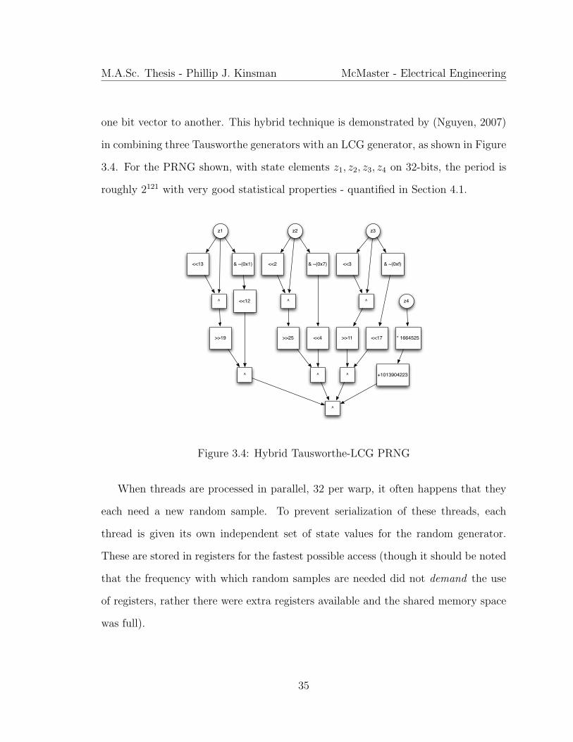
one bit vector to another. This hybrid technique is demonstrated by (Nguyen, 2007)
in combining three Tausworthe generators with an LCG generator, as shown in Figure
3.4. For the PRNG shown, with state elements z1, z2, z3, z4 on 32-bits, the period is
roughly 2121 with very good statistical properties - quantified in Section 4.1.
z1
<<13
^
>>19
& ~(0x1)
<<12
^
z2
<<2
^
>>25
& ~(0x7)
<<4
^
z3
<<3
^
>>11
& ~(0xf)
<<17
^
z4
^
* 1664525
+1013904223
Figure 3.4: Hybrid Tausworthe-LCG PRNG
When threads are processed in parallel, 32 per warp, it often happens that they
each need a new random sample. To prevent serialization of these threads, each
thread is given its own independent set of state values for the random generator.
These are stored in registers for the fastest possible access (though it should be noted
that the frequency with which random samples are needed did not demand the use
of registers, rather there were extra registers available and the shared memory space
was full).
35
M.A.Sc. Thesis - Phillip J. Kinsman McMaster - Electrical Engineering
3.3.4 Memory Access
This section addresses the major memory access requirements of the application and
the strategies used to minimize the extent to which memory accesses bottleneck the
application. The following memory resources are used in the program:
• form factors and cross-sections: approx 40KBytes of read-only data used in
scatter calculations
• density map: approx 2.3MBytes of read-only data used in path sampling and
attenuation calculation
• new photon buffer: host-side buffer storing new photons for processing
• queued photon buffer: per-block buffer storing photons in line for processing,
4096 bytes
• photon queue: per-block buffer that sorts photons into different processing types
Naturally, the photon queue and queued photon buffer are stored in shared mem-
ory. This is because all the elements of these buffers must be accessed with low
latency and shared amongst all the threads in a block. In order to minimize bank
conflicts, the shared memory is allocated with 68 bytes per photon (that is, each
photon spans 17 4-byte words, or 17 banks). There is obviously far too much data
in the cross-sections to store the entire set in shared memory and so it was stored in
constant memory. The new photon buffer is stored in global memory but this does
not prove to be a large bottleneck because the amount of information associated with
a new photon is quite small and it can easily be loaded in a coalesced way.
36
M.A.Sc. Thesis - Phillip J. Kinsman McMaster - Electrical Engineering
Finally, we address the issue of the density map. This is the largest data structure
in the program, at more than 2MB. To further complicate matters, it is frequently
accessed by independent experiments. It therefore has potential to be the major
bottleneck of the program. To address these difficult access requirements, the map
is placed in a texture. Textures can provide reasonable access latencies for read-only
data. Furthermore, they benefit from caching for accesses with high spatial locality.
This is exactly the access pattern of this simulation. Density values of an experiment
are typically accessed from a small region at a time and the density map certainly does
not change throughout the simulation. Futhermore, the addressing logic of the texture
memory offloads the burden of converting the floating-point X,Y,Z coordinates used
in simulation to integer indices. Finally, there is opportunity to leverage the filtering
capabilities of the texture memory to provide even better simulation results than the
original software model by providing a smooth representation of the density (closer
to the real-life situation).
3.3.5 Photon Queues
As was previously discussed, two physical queues are maintained within each thread
block. One queue stores photons that await path sampling (performed on a one-
thread-per-photon basis) and the other stores photons awaiting all other forms of
processing (performed on a one-warp-per-photon basis). Since all the warps within
a block modify the processing queues, it is necessary for their updates to be atomic.
This does not, in fact, create a significant performance bottleneck because the queue
updates represent a small amount of processing time relative to the rest of the pro-
cessing and furthermore, the chances of two warps needing to update the queues at
37
M.A.Sc. Thesis - Phillip J. Kinsman McMaster - Electrical Engineering
the same time is relatively small.
When a warp becomes available for processing, thread 0 of that warp is used as
the control thread, to determine the next processing task. If there are more than
32 photons in the path sampling queue, then the first 32 photons in that queue are
assigned to that warp. Otherwise, the other processing queues are checked in order
for a photon to process. If no photon is available then 32 new photons are loaded from
the host, provided sufficient space is available. It should be again emphasized that
all accesses to the queue must be serialized to prevent corruption from simultaneous
access by multiple threads.
3.3.6 Limitations
Despite the combination of the extremely high bandwidth to the texture memory
and the effective latency-hiding techniques of the GPU architecture, there is still a
memory access issue because there are thousands of concurrent threads competing
for access to the phantom. This highlights one of the fundamental weaknesses of this
approach. As much as access to the phantom can be accelerated, it is still a bottleneck
and more importantly, as device size scales and more MPs are available for processing,
even more threads contend for access to this resource. Consequently, this approach
would be expected to have sub-linear scaling - discussed further in Section 4.2. This
motivates the discussion of the potential for a design which employs distributed access
to the density map, as in the following section.
38
M.A.Sc. Thesis - Phillip J. Kinsman McMaster - Electrical Engineering
3.4 NoC-based Parallel Architecture for FPGAs
In this section we detail our new architecture for accelerating shared dataset MC
simulations through distributed dataset access on custom hardware. First we describe
the architecture and then we provide implementation details for the on-chip network
and processing units. Given the three points established at the end of Section 3.1, it
is suggested that relatively few computational resources are needed for the processing
units and that the top design priority should be minimizing data access latency. In
order to achieve this goal, each processing unit is allocated an equal portion of the
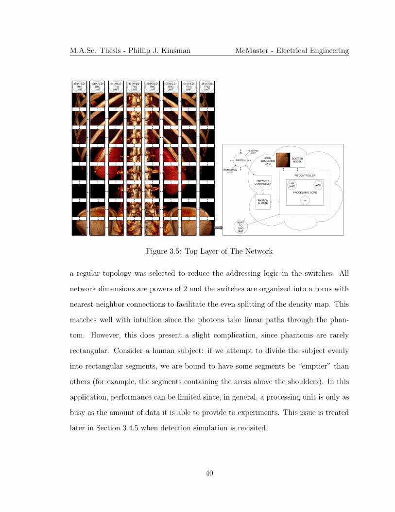
density map as shown in the conceptual diagram of the architecture in Figure 3.5.
The following paragraphs address the fundamental design questions for designing the
communication infrastructure between these PUs. It should be noted that the results
reached in the forthcoming discussion apply specifically to the SPECT simulation
problem. However, the design patterns revealed by these results can be applied more
generally to Monte Carlo simulations where a common data set is shared among many
concurrent experiments.
3.4.1 Network Topology and Organization
Since the data accesses of the experiments are not known a priori, there can be
no guarantee that any one experiment will not access a certain location in memory.
That is, each experiment must be able to have access to every element of the shared
dataset. Therefore, every PU must be connected to every other PU. This motivated
the decision to pair every processing unit to a switch that would connect it to the un-
derlying communication fabric. Because of the massive parallelism that was targeted,
the complexity of the switching fabric must be kept as low as possible. Therefore,
39
M.A.Sc. Thesis - Phillip J. Kinsman McMaster - Electrical Engineering
SHAREDTRIGUNIT
SHAREDTRIGUNIT
SHAREDTRIGUNIT
SHAREDTRIGUNIT
SHAREDTRIGUNIT
SHAREDTRIGUNIT
SHAREDTRIGUNIT
SHAREDTRIGUNIT
SCATTERMODEL
LOCALSIMULATION
DATA
PROCESSING CORE
N-RUNIT MAC
==
PU CONTROLLER
PHOTONBUFFER
NETWORKCONTROLLER
SWITCH
PORT TO
TRIGUNIT
TO BOTTOMLAYER
FROM BOTTOMLAYER
Figure 3.5: Top Layer of The Network
a regular topology was selected to reduce the addressing logic in the switches. All
network dimensions are powers of 2 and the switches are organized into a torus with
nearest-neighbor connections to facilitate the even splitting of the density map. This
matches well with intuition since the photons take linear paths through the phan-
tom. However, this does present a slight complication, since phantoms are rarely
rectangular. Consider a human subject: if we attempt to divide the subject evenly
into rectangular segments, we are bound to have some segments be “emptier” than
others (for example, the segments containing the areas above the shoulders). In this
application, performance can be limited since, in general, a processing unit is only as
busy as the amount of data it is able to provide to experiments. This issue is treated
later in Section 3.4.5 when detection simulation is revisited.
40
M.A.Sc. Thesis - Phillip J. Kinsman McMaster - Electrical Engineering
Detector
PhotonTravel
SimulationNetwork
X
Z
Y
Figure 3.6: Experiment Orientation
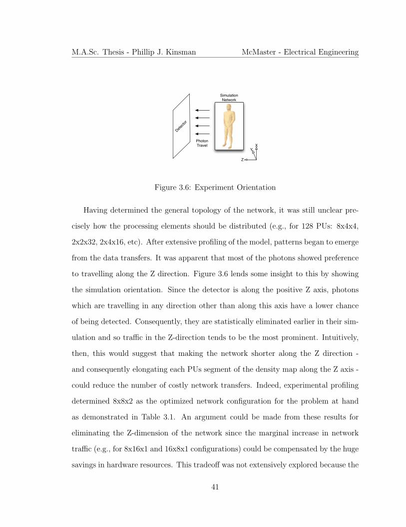
Having determined the general topology of the network, it was still unclear pre-
cisely how the processing elements should be distributed (e.g., for 128 PUs: 8x4x4,
2x2x32, 2x4x16, etc). After extensive profiling of the model, patterns began to emerge
from the data transfers. It was apparent that most of the photons showed preference
to travelling along the Z direction. Figure 3.6 lends some insight to this by showing
the simulation orientation. Since the detector is along the positive Z axis, photons
which are travelling in any direction other than along this axis have a lower chance
of being detected. Consequently, they are statistically eliminated earlier in their sim-
ulation and so traffic in the Z-direction tends to be the most prominent. Intuitively,
then, this would suggest that making the network shorter along the Z direction -
and consequently elongating each PUs segment of the density map along the Z axis -
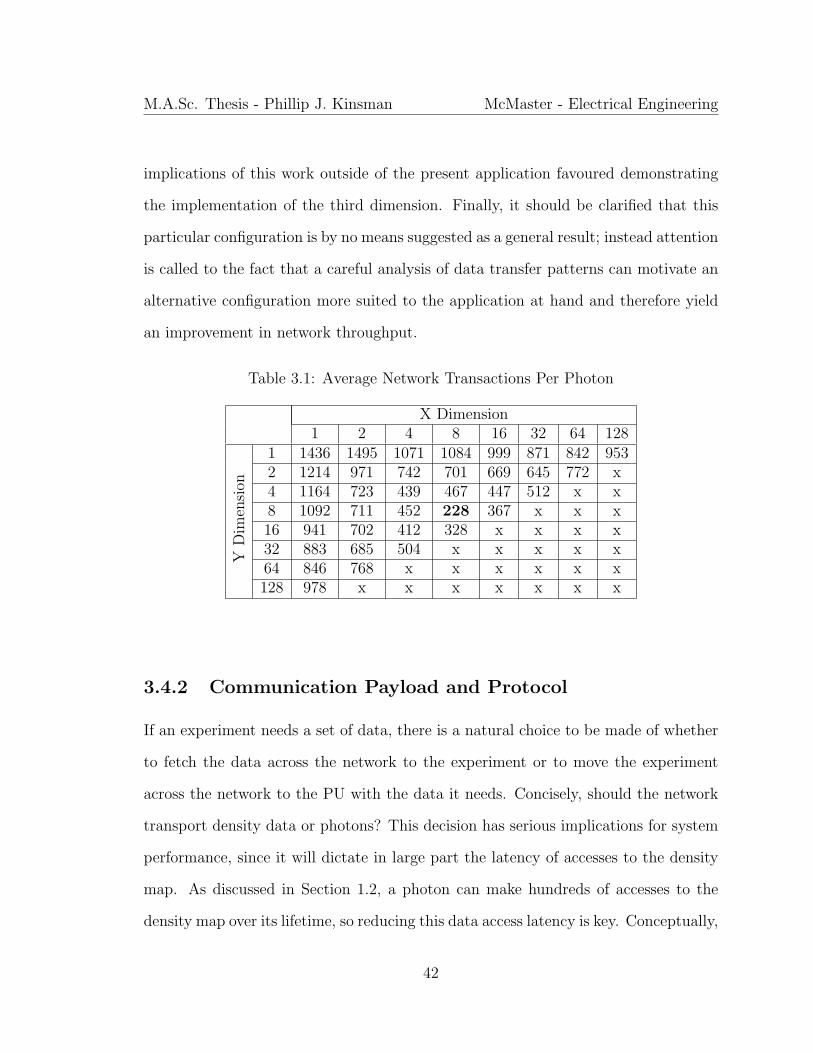
could reduce the number of costly network transfers. Indeed, experimental profiling
determined 8x8x2 as the optimized network configuration for the problem at hand
as demonstrated in Table 3.1. An argument could be made from these results for
eliminating the Z-dimension of the network since the marginal increase in network
traffic (e.g., for 8x16x1 and 16x8x1 configurations) could be compensated by the huge
savings in hardware resources. This tradeoff was not extensively explored because the
41
M.A.Sc. Thesis - Phillip J. Kinsman McMaster - Electrical Engineering
implications of this work outside of the present application favoured demonstrating
the implementation of the third dimension. Finally, it should be clarified that this
particular configuration is by no means suggested as a general result; instead attention
is called to the fact that a careful analysis of data transfer patterns can motivate an
alternative configuration more suited to the application at hand and therefore yield
an improvement in network throughput.
Table 3.1: Average Network Transactions Per Photon
X Dimension1 2 4 8 16 32 64 128
YD
imen
sion
1 1436 1495 1071 1084 999 871 842 9532 1214 971 742 701 669 645 772 x4 1164 723 439 467 447 512 x x8 1092 711 452 228 367 x x x16 941 702 412 328 x x x x32 883 685 504 x x x x x64 846 768 x x x x x x128 978 x x x x x x x
3.4.2 Communication Payload and Protocol
If an experiment needs a set of data, there is a natural choice to be made of whether
to fetch the data across the network to the experiment or to move the experiment
across the network to the PU with the data it needs. Concisely, should the network
transport density data or photons? This decision has serious implications for system
performance, since it will dictate in large part the latency of accesses to the density
map. As discussed in Section 1.2, a photon can make hundreds of accesses to the
density map over its lifetime, so reducing this data access latency is key. Conceptually,
42
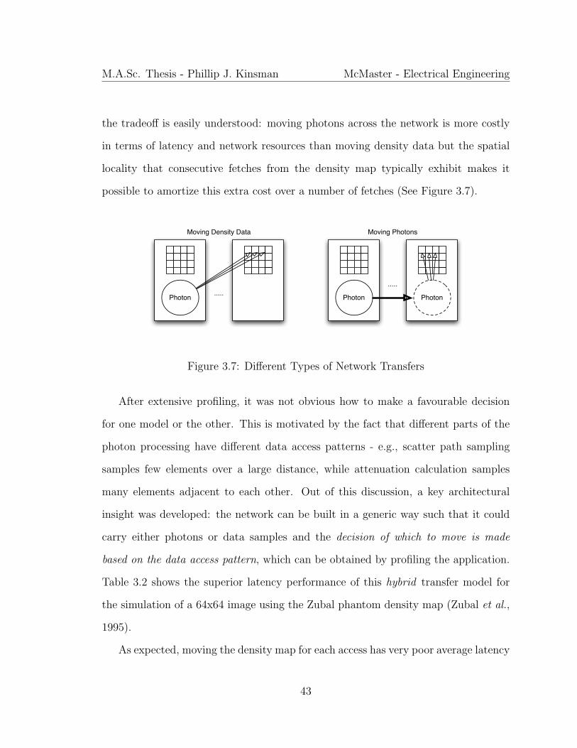
M.A.Sc. Thesis - Phillip J. Kinsman McMaster - Electrical Engineering
the tradeoff is easily understood: moving photons across the network is more costly
in terms of latency and network resources than moving density data but the spatial
locality that consecutive fetches from the density map typically exhibit makes it
possible to amortize this extra cost over a number of fetches (See Figure 3.7).
Photon ..... Photon
.....
Moving Density Data Moving Photons
Photon
Figure 3.7: Different Types of Network Transfers
After extensive profiling, it was not obvious how to make a favourable decision
for one model or the other. This is motivated by the fact that different parts of the
photon processing have different data access patterns - e.g., scatter path sampling
samples few elements over a large distance, while attenuation calculation samples
many elements adjacent to each other. Out of this discussion, a key architectural
insight was developed: the network can be built in a generic way such that it could
carry either photons or data samples and the decision of which to move is made
based on the data access pattern, which can be obtained by profiling the application.
Table 3.2 shows the superior latency performance of this hybrid transfer model for
the simulation of a 64x64 image using the Zubal phantom density map (Zubal et al.,
1995).
As expected, moving the density map for each access has very poor average latency
43
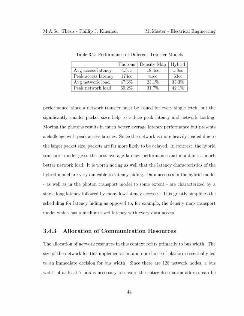
M.A.Sc. Thesis - Phillip J. Kinsman McMaster - Electrical Engineering
Table 3.2: Performance of Different Transfer Models
Photons Density Map HybridAvg access latency 4.3cc 18.4cc 1.8ccPeak access latency 174cc 41cc 63ccAvg network load 47.6% 23.1% 35.3%Peak network load 69.2% 31.7% 42.1%
performance, since a network transfer must be issued for every single fetch, but the
significantly smaller packet sizes help to reduce peak latency and network loading.
Moving the photons results in much better average latency performance but presents
a challenge with peak access latency. Since the network is more heavily loaded due to
the larger packet size, packets are far more likely to be delayed. In contrast, the hybrid
transport model gives the best average latency performance and maintains a much
better network load. It is worth noting as well that the latency characteristics of the
hybrid model are very amicable to latency-hiding. Data accesses in the hybrid model
- as well as in the photon transport model to some extent - are characterized by a
single long latency followed by many low-latency accesses. This greatly simplifies the
scheduling for latency hiding as opposed to, for example, the density map transport
model which has a medium-sized latency with every data access.
3.4.3 Allocation of Communication Resources
The allocation of network resources in this context refers primarily to bus width. The
size of the network for this implementation and our choice of platform essentially led
to an immediate decision for bus width. Since there are 128 network nodes, a bus
width of at least 7 bits is necessary to ensure the entire destination address can be
44

M.A.Sc. Thesis - Phillip J. Kinsman McMaster - Electrical Engineering
stored within one network transfer, or flow unit (flit) - this is covered in more depth
in the upcoming discussion of routing and switching. To simplify the hardware for
building and decoding packets, flits have a width that is a power of two. However,
even with careful attention to reducing the hardware complexity of the switches, a
bus size of 16 would not leave sufficient on-chip resources for the processing units,
resulting in a choice of 8 for the bus width.
Interestingly, it is again possible to take advantage of the application data flow
patterns - discussed in the context of topology, recall Figure 3.6 - when allocating
network resources. Since the primary flow of photons is in the positive Z direction
towards the detector, it is worthwhile to ask whether it is necessary to allocate re-
sources for bidirectional travel in the Z direction. Travel in the XY-plane is essentially
isotropic, so loss of bidirectional travel in either X or Y severely restricts network flow
but simulation indicates that more than 80% of transfers along Z are in the positive Z
direction. For our choice of topology (8x8x2), the discussion is essentially irrelevant,
since wraparound is implemented in all directions but for a larger network, some
resources could be saved by eliminating one direction travel along the Z-axis.
3.4.4 Routing Policies and Switch Structure
The size of the network again had significant influence on the decision for the routing
and switching strategies that were selected. The following were the criteria, in order
of importance:
1. no significant number of photons should be lost and if any are lost, it should
not be in a way that is statistically linked to simulation data
2. the network should employ a dead-lock free routing strategy
45
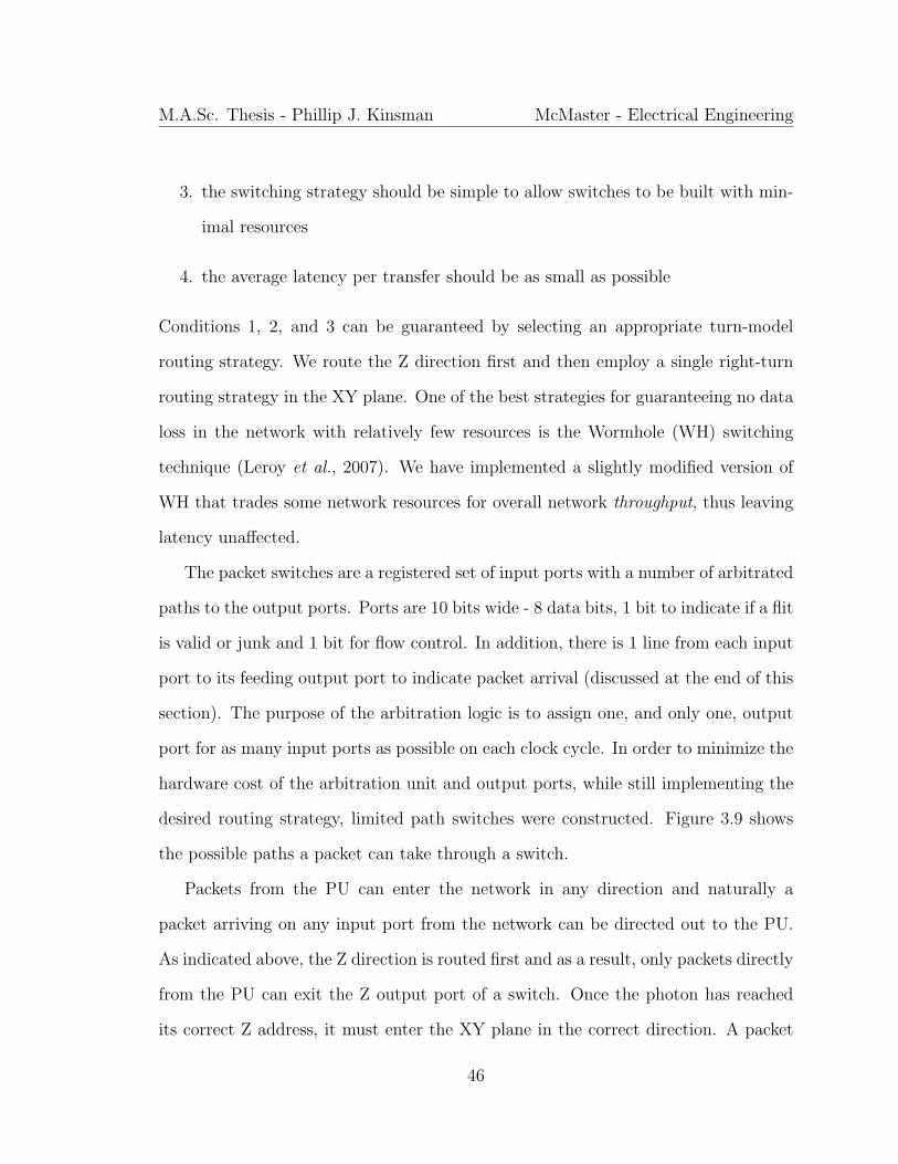
M.A.Sc. Thesis - Phillip J. Kinsman McMaster - Electrical Engineering
3. the switching strategy should be simple to allow switches to be built with min-
imal resources
4. the average latency per transfer should be as small as possible
Conditions 1, 2, and 3 can be guaranteed by selecting an appropriate turn-model
routing strategy. We route the Z direction first and then employ a single right-turn
routing strategy in the XY plane. One of the best strategies for guaranteeing no data
loss in the network with relatively few resources is the Wormhole (WH) switching
technique (Leroy et al., 2007). We have implemented a slightly modified version of
WH that trades some network resources for overall network throughput, thus leaving
latency unaffected.
The packet switches are a registered set of input ports with a number of arbitrated
paths to the output ports. Ports are 10 bits wide - 8 data bits, 1 bit to indicate if a flit
is valid or junk and 1 bit for flow control. In addition, there is 1 line from each input
port to its feeding output port to indicate packet arrival (discussed at the end of this
section). The purpose of the arbitration logic is to assign one, and only one, output
port for as many input ports as possible on each clock cycle. In order to minimize the
hardware cost of the arbitration unit and output ports, while still implementing the
desired routing strategy, limited path switches were constructed. Figure 3.9 shows
the possible paths a packet can take through a switch.
Packets from the PU can enter the network in any direction and naturally a
packet arriving on any input port from the network can be directed out to the PU.
As indicated above, the Z direction is routed first and as a result, only packets directly
from the PU can exit the Z output port of a switch. Once the photon has reached
its correct Z address, it must enter the XY plane in the correct direction. A packet
46

M.A.Sc. Thesis - Phillip J. Kinsman McMaster - Electrical Engineering
...
Input FIFO
...
contentionX ...
almostfullrden
D Qen
DQen
Arbitration
unrouted input portsare stalled
DQ arrived
(a) Wormhole Switching (b) Modified Wormhole Switching
Figure 3.8: Wormhole Switching
may only make one right-turn after entering the XY plane. For example, if a packet
must move in the positive X direction and the negative Y direction, it must select the
negative Y direction first. This facilitates deadlock-free routing with an extremely
simple arbitration unit. Once an input port has been directed to an output port,
it locks that port until the entire packet is transmitted - indicated by the arrival of
the footer. To demonstrate how this process occurs, part of a switch is shown in
Figure 3.8b, with the full implementation being given in Figure 3.9. If an output
port is unlocked and two or more input ports compete for simultaneous access to it,
the assignment is made with the following priority:
1. Straight-through traffic (S)
2. Other in-plane traffic (T)
3. Out-of-plane traffic (Z)
4. Processing unit (P)
Input ports which are not assigned are stalled until the desired output port opens.
The mechanism for this stalling is very similar to the strategy employed by wormhole
47
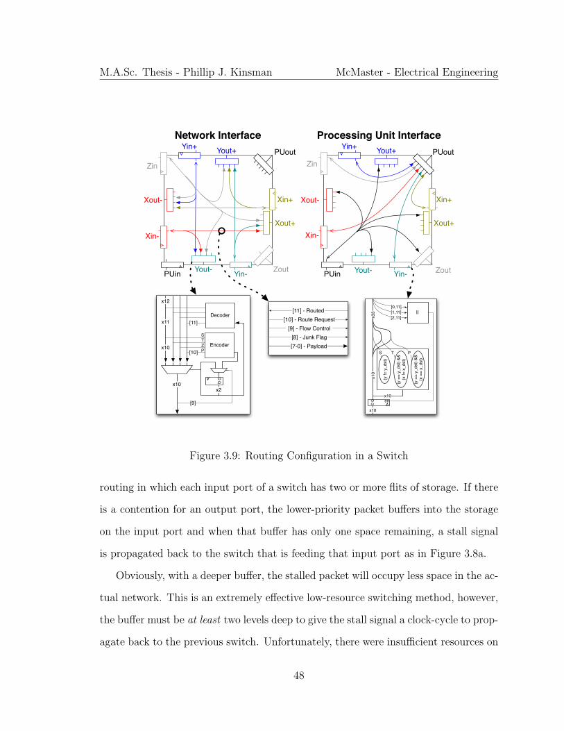
M.A.Sc. Thesis - Phillip J. Kinsman McMaster - Electrical Engineering
Yout+
Yout-
Xout+
Xout-
Zin
Yin+
Yin-
Xin+
Xin-
Zout
PUout
Network Interface Processing Unit Interface
PUin
EncoderD Q
x2x10
[9]
x11
x10[10]
STZP
Decoder
x12
[11]
[11] - Routed[10] - Route Request
[9] - Flow Control[8] - Junk Flag[7-0] - Payload
(y !=
y_d
st)
(y =
= y_
dst)
&&
(x !=
x_d
st)
(y =
= y_
dst)
&&
(x =
= x_
dst)
x10
D Q
x33
en
[0,11][1,11][2,11]
||
S T P
x10
x10
Yout+
Yout-
Xout+
Xout-
Zin
Yin+
Yin-
Xin+
Xin-
Zout
PUout
PUin
Figure 3.9: Routing Configuration in a Switch
routing in which each input port of a switch has two or more flits of storage. If there
is a contention for an output port, the lower-priority packet buffers into the storage
on the input port and when that buffer has only one space remaining, a stall signal
is propagated back to the switch that is feeding that input port as in Figure 3.8a.
Obviously, with a deeper buffer, the stalled packet will occupy less space in the ac-
tual network. This is an extremely effective low-resource switching method, however,
the buffer must be at least two levels deep to give the stall signal a clock-cycle to prop-
agate back to the previous switch. Unfortunately, there were insufficient resources on
48
M.A.Sc. Thesis - Phillip J. Kinsman McMaster - Electrical Engineering
chip to provide two buffers for every input port, so a slightly different approach was
taken (see Figure 3.8b). Only one level of input buffering is allocated and if a header
arrives in that buffer that cannot be routed, the input port is disabled. This causes
dropping of payload flits to occur. To resolve this, the packets are transmitted cycli-
cally from the source PU. Once a packet has locked a path to the destination node, it
propagates an arrival signal back to the source, which then transmits the remainder
of the packet with a marker in the footer to allow the receiver to align the packet.
Naturally, this cyclic transmission results in extra network transfers. Although this
can waste some cycles in the source PU’s network controller, network throughput is
not negatively impacted since these redundant flits are in a portion of the network
that is locked to any other traffic and in fact, the blocking of the network controller
actually turns out to be a very effective and simple way to limit network congestion.
3.4.5 Processing Unit Structure
Based on our choice for the implementation platform, more than 40% of the device’s
logic resources were consumed by the on-chip network. This motivated a PU design
that is cost-effective without impacting the accuracy of the results.
Each PU has allocated to it, on average, two and a half 18-kbit BlockRAMs (as
detailed in the experimental section, we have used a Xilinx FPGA). Of these, one
is allocated for density map storage, one is allocated for a photon buffer, and one is
shared with the neighbouring PU, storing the scatter models and some simulation-
constant data.
Based heavily on the work from (Aslan et al., 2009), a single Newton-Rhapson
49
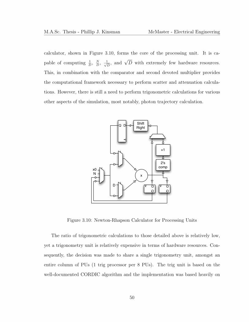
M.A.Sc. Thesis - Phillip J. Kinsman McMaster - Electrical Engineering
calculator, shown in Figure 3.10, forms the core of the processing unit. It is ca-
pable of computing 1D
, ND
, 1√D
, and√D with extremely few hardware resources.
This, in combination with the comparator and second devoted multiplier provides
the computational framework necessary to perform scatter and attenuation calcula-
tions. However, there is still a need to perform trigonometric calculations for various
other aspects of the simulation, most notably, photon trajectory calculation.
x0N
D
x
2'scomp
+1
ShiftRightDQ
DQ
DQ
Figure 3.10: Newton-Rhapson Calculator for Processing Units
The ratio of trigonometric calculations to those detailed above is relatively low,
yet a trigonometry unit is relatively expensive in terms of hardware resources. Con-
sequently, the decision was made to share a single trigonometry unit, amongst an
entire column of PUs (1 trig processor per 8 PUs). The trig unit is based on the
well-documented CORDIC algorithm and the implementation was based heavily on
50
M.A.Sc. Thesis - Phillip J. Kinsman McMaster - Electrical Engineering
the work from (Angarita et al., 2005). Arbitration is performed on a first-come-first-
served basis and each CORDIC unit has one level of input buffering. Our profiling
reveals that only 0.0027% of CORDIC commands arrive at a full CORDIC unit and
need to be backed up into the network and hence we conclude that these units are
not bottlenecks to computation. Each processing engine is also equipped with a
pseudo-random number generator, discussed in Section 3.4.6.
The allocation of the resources for the arithmetic units required significant ex-
perimental profiling. It is critical in this application to preserve the accuracy of the
reconstructed image, yet this must be balanced with the tight resource constraints.
The resources required to implement a custom floating-point datapath at each PU
would drastically limit the number of PUs and hence the possible parallelism. There-
fore, the application was mapped into fixed-point arithmetic but the evaluation of
the impact of finite precision on the quality of the reconstructed image is complicated
by the random nature of the simulation. To overcome this, a two-fold approach was
taken to establish the appropriate data-widths: in the first phase, the experiments
were evaluated individually to understand the relative impact on accuracy of each
variable. In the second phase, the experiments were evaluated in the context of the
simulation. The SNR of the fixed-point images - taking the floating-point images
as reference - is insufficient to draw strong conclusions about the accuracy because
of the simulation randomness and because the images are so heavily dependent on
the simulation dataset. Consequently, the convergence of the images with increasing
simulation size was used to evaluate the simulation accuracy as shown in Figure 4.1.
Table 3.3 gives the data-widths that were empirically found to provide a reasonable
balance between resource usage and reconstruction accuracy.
51
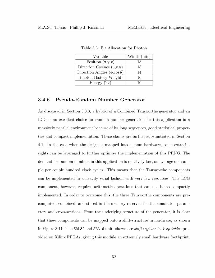
M.A.Sc. Thesis - Phillip J. Kinsman McMaster - Electrical Engineering
Table 3.3: Bit Allocation for Photon
Variable Width (bits)Position (x,y,z) 18
Direction Cosines (u,v,w) 18Direction Angles (φ,cos θ) 14
Photon History Weight 16Energy (hv) 10
3.4.6 Pseudo-Random Number Generator
As discussed in Section 3.3.3, a hybrid of a Combined Tausworthe generator and an
LCG is an excellent choice for random number generation for this application in a
massively parallel environment because of its long sequences, good statistical proper-
ties and compact implementation. These claims are further substantiated in Section
4.1. In the case when the design is mapped into custom hardware, some extra in-
sights can be leveraged to further optimize the implementation of this PRNG. The
demand for random numbers in this application is relatively low, on average one sam-
ple per couple hundred clock cycles. This means that the Tausworthe components
can be implemented in a heavily serial fashion with very few resources. The LCG
component, however, requires arithmetic operations that can not be so compactly
implemented. In order to overcome this, the three Tausworthe components are pre-
computed, combined, and stored in the memory reserved for the simulation param-
eters and cross-sections. From the underlying structure of the generator, it is clear
that these components can be mapped onto a shift-structure in hardware, as shown
in Figure 3.11. The SRL32 and SRL16 units shown are shift register look-up tables pro-
vided on Xilinx FPGAs, giving this module an extremely small hardware footbprint.
52

M.A.Sc. Thesis - Phillip J. Kinsman McMaster - Electrical Engineering
The LCG component leverages the hardware for the NR calculator, already avail-
able in the PU, and is computed on-demand and combined with the precomputed
Tausworthe component.
SRL32 SRL16DD
FSM
CE CE
Figure 3.11: Shift-Structure Implementation of Tausworthe PRNG
3.5 Scaling the NoC-based Architecture for Increased
Parallelism
The long-term trend of increasing on-chip resources in computing hardware, famously
predicted by (Moore, 1965), has motivated a focus on scalability amongst hardware
designers. This is particularly important in the case where an FPGA is the target
device for a design, since the design’s scalability will dictate how effectively it is able
to leverage larger devices as they are brought to market. We propose that one of the
most significant advantages to the proposed architecture is the simplicity of scaling
it, not only to larger devices, but to multiple devices as well. That the design scales
naturally onto larger devices is intuitive, because the nature of the processing network
53
M.A.Sc. Thesis - Phillip J. Kinsman McMaster - Electrical Engineering
is such that it can be extended in a parameterized way. Indeed, results reported in
Table 4.3 confirm this intuition. However, the scaling of the design across multiple
devices presents a number of challenges and so this section describes the methodology
we have developed for overcoming these challenges.
3.5.1 Scaling to Multiple FPGAs
Before describing the methodology for extending the design to multiple devices, some
terms should be introduced to facilitate the discussion. For the purposes of the
discussion, we consider a single link , that is, a single physical connection between two
FPGAs: A and B. By developing insight into mapping network traffic onto a single
link, our results here can be extended to many different multi-FPGA systems with
different topologies and configurations. The variable N is used to denote a network
node and we define the predicates A(N) and B(N) to indicate on which of the two
linked devices N resides, noting that
(A(N)→ ¬B(N)) ∧ (B(N)→ ¬A(N))
Two network nodes are said to be bidirectionally connected if X(Ni, Nj) = >. This
connection is denoted as Xi,j and we define the set of all connections that are imple-
mented on the link as follows:
X = {Xi,j : A(Ni) ∧B(Nj) ∨B(Ni) ∧ A(Nj)}
54

M.A.Sc. Thesis - Phillip J. Kinsman McMaster - Electrical Engineering
The set of all network nodes that communicate across the link is given by
N = {Ni : ∃j (Xi,j ∈ X )}
Finally, the traffic in clock cycle t of the simulation is defined as
T ij (t) =
1 Ni transfers one non-junk flit to Nj in clock cycle t
0 otherwise
Therefore, we can describe the data transfer rate on connection Xi,j for flit-width f
in clock cycle t as
R(t,Xi,j) = f ·(T i
j (t) + T ji (t)
)and similarly we define the average and maximum data transfer rate on Xi,j over the
timespan [a, b] to be
Ravg([a, b], Xi,j) =
∫ ba R(t,Xi,j)dt
b− a
Rmax(Xi,j) = 2f
The focus of this discussion is to determine how the traffic over X can be scheduled
onto a set of bi-directional virtual channels C = {Ci : 0 ≤ i < n} that are constrained
in their aggregate bandwidth1. This mapping should be done in a way that minimizes
transfer latency and probability of buffer overflow as a function of aggregate buffer
size. For the purposes of the discussion, the mapping of these virtual channels onto
the physical lines of the link is abstracted, though it is assumed that n virtual channels
can be implemented with a small2, constant latency on a physical link having total
1for the duration of this thesis, bandwidth is considered in bits/cc2this qualifier is difficult to quantify but because of the latency hiding implemented by the
55
M.A.Sc. Thesis - Phillip J. Kinsman McMaster - Electrical Engineering
bandwidth BL provided that
1
1− σc
n∑i=0
B(Ci) ≤ (1− σl)BL (3.1)
where
• σl is the control overhead for the physical link itself (as a percentage of link
bandwidth)
• σc is the control overhead for each virtual channel
• B(Ci) is the total bandwidth in both directions of channel Ci
This section details the incremental development which lead to the approach which
is currently taken in the design. For each approach described, custom hardware was
designed, validated through simulation, and executed and measured as described in
Section 4.3.2.
An obvious approach to mapping the traffic onto the virtual channels would be
to assign one virtual channel per connection such that Ck = Xi,j and each channel
is allocated bandwidth (1 − σc)B(Ck) > Rmax(Xi,j). This solution is optimal under
the two criteria established above since the latency is 0 and there is no possiblity for
buffer overflow. Unfortunately, such an optimal solution fails to address the more
general case where insufficient link bandwidth is available to support the worst-case
scenario for data transfer, i.e., when
∀t, i, j : R(t,Xi,j) = Rmax(Xi,j)
application, experimental profiling reveals that a latency in the high tens to low hundreds of clockcycles can be tolerated without a noticable impact on system performance
56
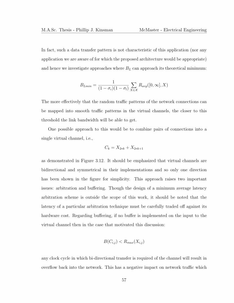
M.A.Sc. Thesis - Phillip J. Kinsman McMaster - Electrical Engineering
In fact, such a data transfer pattern is not characteristic of this application (nor any
application we are aware of for which the proposed architecture would be appropriate)
and hence we investigate approaches where BL can approach its theoretical minimum:
BLmin =1
(1− σc)(1− σl)
∑X∈X
Ravg([0,∞], X)
The more effectively that the random traffic patterns of the network connections can
be mapped into smooth traffic patterns in the virtual channels, the closer to this
threshold the link bandwidth will be able to get.
One possible approach to this would be to combine pairs of connections into a
single virtual channel, i.e.,
Ck = X2∗k +X2∗k+1
as demonstrated in Figure 3.12. It should be emphasized that virtual channels are
bidirectional and symmetrical in their implementations and so only one direction
has been shown in the figure for simplicity. This approach raises two important
issues: arbitration and buffering. Though the design of a minimum average latency
arbitration scheme is outside the scope of this work, it should be noted that the
latency of a particular arbitration technique must be carefully traded off against its
hardware cost. Regarding buffering, if no buffer is implemented on the input to the
virtual channel then in the case that motivated this discussion:
B(Ci,j) < Rmax(Xi,j)
any clock cycle in which bi-directional transfer is required of the channel will result in
overflow back into the network. This has a negative impact on network traffic which
57
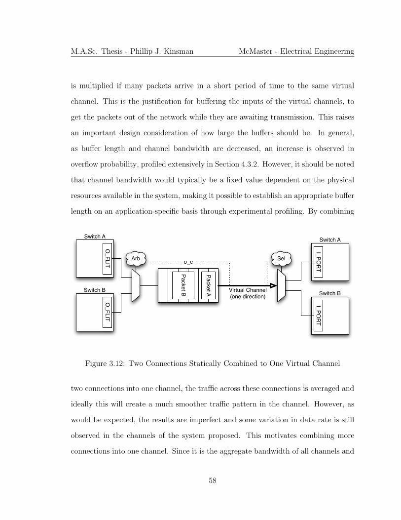
M.A.Sc. Thesis - Phillip J. Kinsman McMaster - Electrical Engineering
is multiplied if many packets arrive in a short period of time to the same virtual
channel. This is the justification for buffering the inputs of the virtual channels, to
get the packets out of the network while they are awaiting transmission. This raises
an important design consideration of how large the buffers should be. In general,
as buffer length and channel bandwidth are decreased, an increase is observed in
overflow probability, profiled extensively in Section 4.3.2. However, it should be noted
that channel bandwidth would typically be a fixed value dependent on the physical
resources available in the system, making it possible to establish an appropriate buffer
length on an application-specific basis through experimental profiling. By combining
O_FLIT
Switch A
Switch BO
_FLIT
Packet A
Packet B Virtual Channel(one direction)
Arb
Switch A
Switch B
I_PORT
I_PORT
Selσ_c
Figure 3.12: Two Connections Statically Combined to One Virtual Channel
two connections into one channel, the traffic across these connections is averaged and
ideally this will create a much smoother traffic pattern in the channel. However, as
would be expected, the results are imperfect and some variation in data rate is still
observed in the channels of the system proposed. This motivates combining more
connections into one channel. Since it is the aggregate bandwidth of all channels and
58
M.A.Sc. Thesis - Phillip J. Kinsman McMaster - Electrical Engineering
not the individual bandwidth of any one channel that is constrained by the system, if
four connections are combined into one channel, it can have twice the bandwidth of
the channel combining two connections. In addition to this, it averages traffic over a
larger pool of connections, smoothing the traffic in the channel significantly. Finally,
by the same argument as the bandwidth, double the buffer space can be allocated to
this channel at no extra hardware cost. Though this would seem to be an excellent
solution and even would motivate curiousity into combining even more connections
into a single channel, it presents a challenge in terms of arbitration and transfer
latency. As the number of inputs to a channel increases, arbitration becomes more
complex, which can have a non-trivial hardware cost in terms of arbitration logic.
More significantly, by combining the connections, their transfer latencies also become
linked. That is, if a large burst arrives on one connection, all the other connections will
be delayed as this is processed. The exact impact this will have on system performance
depends entirely on the system. For example, in the present implementation, the effect
is rather marginal because of the great care put into developing the hardware in a
way that masks network transfer latencies. Other applications, though, may be more
sensitive. The tradeoffs discussed here are demonstrated in Tables 4.5 to 4.7.
Though generally good performance is exhibited by this approach as constraints on
channel bandwidth are tightened, it suffers the limitation that by statically assigning
certain connections to a channel, there is no way to dynamically accomodate the
traffic anomalies inevitable in large random simulations. Further, because there is
no knowledge of traffic patterns a priori, it is impossible to give any definite bounds
on the communication characteristics across the link, which could be problematic
for some applications. This is the motivation for a dynamic approach to scheduling
59
M.A.Sc. Thesis - Phillip J. Kinsman McMaster - Electrical Engineering
data transfers on channels. As before, fewer channels are allocated than there are
connections. In this case, though, instead of statically grouping the connections
onto the channels, when a packet arrives on a connection, it will be directed to the
channel with the shortest input queue. Assuming equal buffer lengths are assigned to
all channels, this optimizes both criteria for link performance (latency and overflow
probability).
The major challenge with this approach is that the hardware cost would be ex-
pected to be quite large. Consider allocating four channels and compare this to the
case above where each of the four channels would have combined four connections.
In this case, instead of multiplexing four connections onto one channel, each of the
16 connections must be multiplexed onto each of the channels and furthermore, some
very sophisticated arbitration must be implemented to decide in real time the output
channel for an arriving packet. Furthermore, on the arriving side a sophisticated de-
multiplexing circuit must be implemented to ensure that packets are correctly routed
to their destination node. Though these considerations would typically seem quite
grim, because of the underlying architecture of the design this approach can actually
be implemented with virtually no hardware cost. Network-on-Chip architectures fa-
cilitate exactly this kind of situation where data transfer is dynamically determined
and hence the existing hardware can be leveraged to implement this technique quite
effectively. A simplified implementation with four connections dynamically scheduled
to two channels is shown in Figure 3.13.
Section 4.3.2 demonstrates how this approach outperforms the static approach in
every metric under various system configurations. Hence, the rest of this section is
devoted to describing how the architecture described in Section 3.4 is scaled using
60

M.A.Sc. Thesis - Phillip J. Kinsman McMaster - Electrical Engineering
Packet A
Packet B Virtual Channel(one direction shown)
ArbSel
σ_cSw A0
Sw B0
Sw A1
Sw B1
Packet C Virtual Channel(one direction shown)
ArbSel
Sw A0
Sw B0
Sw A1
Sw B1
Figure 3.13: Four Connections Dynamically Combined to Two Virtual Channels
this technique. Firstly, it should be noted that the network on a single FPGA is
implemented as a torus but, when extended to multiple FPGAs, it is simplified to a
mesh. This is done because the routing resources previously used for wrap-around are
now used for communication between devices. Secondly, the inter-FPGA connections
are made along the smallest faces of the network. This leverages the result from
Section 3.4.3 to reduce traffic between FPGAs because the connection is bandwidth-
constrained. Hence, the 8x2 face of the network is connected across devices and the
set X is assigned to the channels in such a way that each node’s neighbors are assigned
to channels which are distinct both from each other and from the node itself as in
Table 3.4. Then, the current buffer length of each channel is used by each switch
Table 3.4: Channel Assignment for Boundary Nodes
x = 0 x = 1 x = 2 x = 3 x = 4 x = 5 x = 6 x = 7z = 0 0 2 1 3 0 2 1 3z = 1 1 3 0 2 1 3 0 2
61
M.A.Sc. Thesis - Phillip J. Kinsman McMaster - Electrical Engineering
on the boundary to determine whether it should deliver an incoming packet directly
to its channel or whether it should route the packet to a neighbor for transmission.
That is, for outbound traffic in the boundary plane of switches, routing decisions are
made based on channel load and not destination as is the case everywhere else on the
network. It should be noted that incoming traffic from the link is still routed in the
usual way by comparison of current location to destination. Results for this approach
are given in Section 4.3.2
3.6 Summary
This chapter has described in detail the contribution of this work. Firstly, the com-
putational patterns of the application of interest were discussed. This was done to
inform the design decisions discussed in Sections 3.2 to 3.4 as single- and multi-
threaded software based approaches were described, leading to a full explanation of
our custom hardware approach. Finally, Section 3.5 considers approaches for scal-
ing our new parallel architecture for SPECT simulation to multiple compute devices.
The next chapter interprets the results that were obtained from the implementations
discussed in this chapter.
62
Chapter 4
Experimental Results
Having detailed the implementation of custom hardware for accelerating the simula-
tion of SPECT imaging based on the SIMIND Monte Carlo software in Chapter 3, the
purpose of this chapter is to outline the results that were obtained from this imple-
mentation in order to compare it against the current art in this field. Firstly, a brief
discussion is given of randomness and criteria are established for assessing the quality
of the reproduced images. Then, the acceleration results of the GPGPU-based imple-
mentation discussed in Section 3.3 are given in Section 4.2. This is done to provide
a basis against which to compare the acceleration results reported in Section 4.3 for
the NoC-based architecture for custom hardware described in Section 3.4. It should
be noted that all acceleration results are reported with respect to the optimized CPU
implementation discussed in Section 3.2, which reproduces images that are identical
matches to the original FORTRAN software model.
63
M.A.Sc. Thesis - Phillip J. Kinsman McMaster - Electrical Engineering
4.1 Randomness and Image Quality
As was introduced in Section 3.3.3, the quality of the PRNG used by the simulation
has a significant impact on the reproduced image, yet is extremely difficult to quantify.
Though a discussion of the techniques for analyzing PRNGs is outside the scope of this
work, we chose the Diehard battery of tests (Marsaglia, 1995) to judge the PRNGs
because it is widely accepted as a standard. Vectors of 25 million random integers on
32-bits were used to test both the GNU implementation of rand() that was used in
the original software model and the Hybrid Combined Tausworthe generator proposed
in Section 3.3.3. GNU rand() fails nearly every one of the Diehard tests, performing
well only on the Birthday Spacings test and the Overlapping 5-Permutation test.
The lower bits performed especially poorly. In contrast to this, the Hybrid Combined
Tausworthe generator passed every single test in the suite. This is not to say that it is
a perfect PRNG but rather that it has very good performance in generating random
sets of numbers on the scale of those required for this application.
In order to assess the quality of the reconstructed images, there is fortunately a
slightly more systematic approach that can be used. Both signal-to-noise ratio (SNR)
and peak signal-to-noise ratio (PSNR) were used to judge the quality of the images
reconstructed by the FPGA implementation. SNR is a commonly accepted metric
in science for comparing the level of the true signal to the level of background noise
present, while PSNR is often used in multimedia applications to judge the human
perception of image reproduction errors - most commonly in connection with the
performance of a compression codec. The SNR is defined as:
SNRdB = 10 log10
∑A2
ref∑(A− Aref )2 (4.1)
64
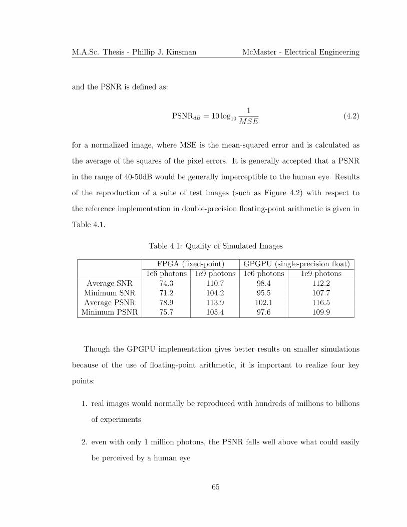
M.A.Sc. Thesis - Phillip J. Kinsman McMaster - Electrical Engineering
and the PSNR is defined as:
PSNRdB = 10 log10
1
MSE(4.2)
for a normalized image, where MSE is the mean-squared error and is calculated as
the average of the squares of the pixel errors. It is generally accepted that a PSNR
in the range of 40-50dB would be generally imperceptible to the human eye. Results
of the reproduction of a suite of test images (such as Figure 4.2) with respect to
the reference implementation in double-precision floating-point arithmetic is given in
Table 4.1.
Table 4.1: Quality of Simulated Images
FPGA (fixed-point) GPGPU (single-precision float)1e6 photons 1e9 photons 1e6 photons 1e9 photons
Average SNR 74.3 110.7 98.4 112.2Minimum SNR 71.2 104.2 95.5 107.7Average PSNR 78.9 113.9 102.1 116.5
Minimum PSNR 75.7 105.4 97.6 109.9
Though the GPGPU implementation gives better results on smaller simulations
because of the use of floating-point arithmetic, it is important to realize four key
points:
1. real images would normally be reproduced with hundreds of millions to billions
of experiments
2. even with only 1 million photons, the PSNR falls well above what could easily
be perceived by a human eye
65
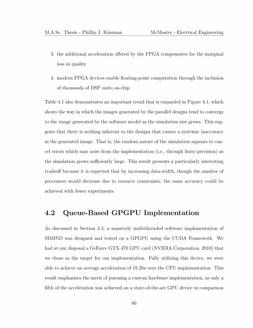
M.A.Sc. Thesis - Phillip J. Kinsman McMaster - Electrical Engineering
3. the additional acceleration offered by the FPGA compensates for the marginal
loss in quality
4. modern FPGA devices enable floating-point computation through the inclusion
of thousands of DSP units on-chip
Table 4.1 also demonstrates an important trend that is expanded in Figure 4.1, which
shows the way in which the images generated by the parallel designs tend to converge
to the image generated by the software model as the simulation size grows. This sug-
gests that there is nothing inherent to the designs that causes a systemic inaccuracy
in the generated image. That is, the random nature of the simulation appears to can-
cel errors which may arise from the implementation (i.e., through finite precision) as
the simulation grows sufficiently large. This result presents a particularly interesting
tradeoff because it is expected that by increasing data-width, though the number of
processors would decrease due to resource constraints, the same accuracy could be
achieved with fewer experiments.
4.2 Queue-Based GPGPU Implementation
As discussed in Section 3.3, a massively multithreaded software implementation of
SIMIND was designed and tested on a GPGPU using the CUDA Framework. We
had at our disposal a GeForce GTX 470 GPU card (NVIDIA Corporation, 2010) that
we chose as the target for our implementation. Fully utilizing this device, we were
able to achieve an average acceleration of 19.28x over the CPU implementation. This
result emphasizes the merit of pursuing a custom hardware implementation, as only a
fifth of the acceleration was achieved on a state-of-the-art GPU device in comparison
66

M.A.Sc. Thesis - Phillip J. Kinsman McMaster - Electrical Engineering
70
75
80
85
90
95
100
105
110
115
5 6 7 8 9 10
SNR
(dB)
log10 Number of Experiments
FPGAGPU
Figure 4.1: Image SNR vs. Simulation Size
to our FPGA implementation, which was deployed on a Xilinx device family that is
not as recent as the GPU device family.
4.3 NoC-Based FPGA Implementation
The NoC architecture described in this work was modelled and verified in software
before being implemented in hardware. The target platform was the Berkeley Emu-
lation Engine 2 (BEE2) (Chang et al., 2005) which contains four Xilinx Virtex-II Pro
FPGAs (XILINX, Inc., 2011b), each with 74,448 Logic Cells and 738kB of available
on-chip memory. This platform is depicted in Figure 4.3.
67
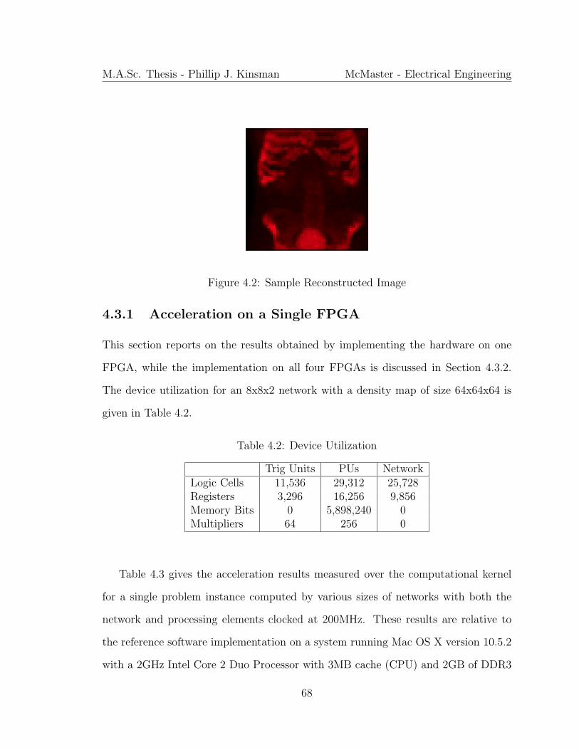
M.A.Sc. Thesis - Phillip J. Kinsman McMaster - Electrical Engineering
Figure 4.2: Sample Reconstructed Image
4.3.1 Acceleration on a Single FPGA
This section reports on the results obtained by implementing the hardware on one
FPGA, while the implementation on all four FPGAs is discussed in Section 4.3.2.
The device utilization for an 8x8x2 network with a density map of size 64x64x64 is
given in Table 4.2.
Table 4.2: Device Utilization
Trig Units PUs NetworkLogic Cells 11,536 29,312 25,728Registers 3,296 16,256 9,856Memory Bits 0 5,898,240 0Multipliers 64 256 0
Table 4.3 gives the acceleration results measured over the computational kernel
for a single problem instance computed by various sizes of networks with both the
network and processing elements clocked at 200MHz. These results are relative to
the reference software implementation on a system running Mac OS X version 10.5.2
with a 2GHz Intel Core 2 Duo Processor with 3MB cache (CPU) and 2GB of DDR3
68
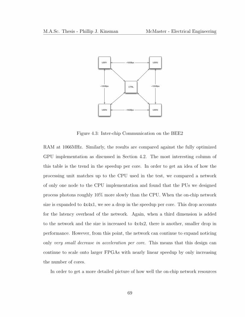
M.A.Sc. Thesis - Phillip J. Kinsman McMaster - Electrical Engineering
USR1
CTRL
USR3USR4
USR2~10GBps
~10GBps ~10GBps
~10GBps
Figure 4.3: Inter-chip Communication on the BEE2
RAM at 1066MHz. Similarly, the results are compared against the fully optimized
GPU implementation as discussed in Section 4.2. The most interesting column of
this table is the trend in the speedup per core. In order to get an idea of how the
processing unit matches up to the CPU used in the test, we compared a network
of only one node to the CPU implementation and found that the PUs we designed
process photons roughly 10% more slowly than the CPU. When the on-chip network
size is expanded to 4x4x1, we see a drop in the speedup per core. This drop accounts
for the latency overhead of the network. Again, when a third dimension is added
to the network and the size is increased to 4x4x2, there is another, smaller drop in
performance. However, from this point, the network can continue to expand noticing
only very small decrease in acceleration per core. This means that this design can
continue to scale onto larger FPGAs with nearly linear speedup by only increasing
the number of cores.
In order to get a more detailed picture of how well the on-chip network resources
69
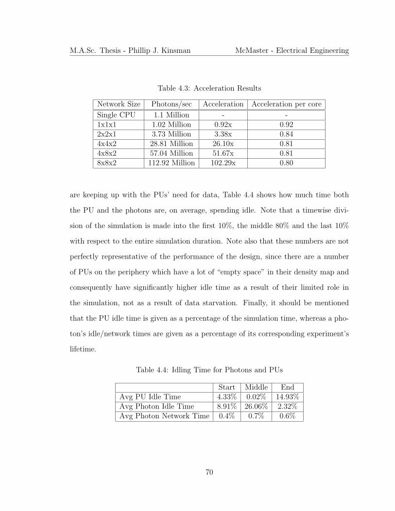
M.A.Sc. Thesis - Phillip J. Kinsman McMaster - Electrical Engineering
Table 4.3: Acceleration Results
Network Size Photons/sec Acceleration Acceleration per core
Single CPU 1.1 Million - -1x1x1 1.02 Million 0.92x 0.922x2x1 3.73 Million 3.38x 0.844x4x2 28.81 Million 26.10x 0.814x8x2 57.04 Million 51.67x 0.818x8x2 112.92 Million 102.29x 0.80
are keeping up with the PUs’ need for data, Table 4.4 shows how much time both
the PU and the photons are, on average, spending idle. Note that a timewise divi-
sion of the simulation is made into the first 10%, the middle 80% and the last 10%
with respect to the entire simulation duration. Note also that these numbers are not
perfectly representative of the performance of the design, since there are a number
of PUs on the periphery which have a lot of “empty space” in their density map and
consequently have significantly higher idle time as a result of their limited role in
the simulation, not as a result of data starvation. Finally, it should be mentioned
that the PU idle time is given as a percentage of the simulation time, whereas a pho-
ton’s idle/network times are given as a percentage of its corresponding experiment’s
lifetime.
Table 4.4: Idling Time for Photons and PUs
Start Middle EndAvg PU Idle Time 4.33% 0.02% 14.93%Avg Photon Idle Time 8.91% 26.06% 2.32%Avg Photon Network Time 0.4% 0.7% 0.6%
70
M.A.Sc. Thesis - Phillip J. Kinsman McMaster - Electrical Engineering
These numbers again match intuition very well. In the beginning of the simula-
tion, many photons are being birthed and a critical mass of in-simulation photons is
building. While that is happening, the full effect of most latencies will be borne by
the PU. As the simulation progresses, PUs move to having 3-7 active experiments
at one time, meaning that the effect of the latencies felt from data accesses where
the density map is fetched (refer to Section 3.1 Point #3) moves to the experiments
instead, so that the PUs can keep active. This explains the notable increase in ex-
periment idle time, however, it must be remembered that experiment idle time does
not necessarily cost simulation time. Rather it costs extra space in the processing
buffer. Finally, towards the end of the simulation, the last number of photons are be-
ing cleared out and this causes an exaggeration of the same effect that was discussed
for the beginning of the simulation. Also in accordance with intuition, the amount
of an experiment’s duration that is spent with the photon in the network does not
change substantially for the duration of the simulation.
As a final note, if we would employ a larger FPGA, the design can scale through
parameterization to improve speedup and resolution. If the memory capacity of
the device is increased, the resolution of the phantom can be increased in direct
proportion, with a corresponding increase in image quality. This occurs without
a significant increase in simulation time because the way in which the phantom is
sampled does not increase computation with higher resolution. This effect is reported
on further in Section 4.3.2. Similarly, the results in Table 4.3 suggest near linear
scaling of acceleration with an increase in logic resources. Therefore, given an FPGA
of 25-30x the logic resources and 8-10x the memory resources of the Virtex-II Pro, as
is the case with some large state-of-the-art devices (XILINX, Inc., 2011a), we would
71
M.A.Sc. Thesis - Phillip J. Kinsman McMaster - Electrical Engineering
expect to achieve an 8x increase in resolution and conservatively an additional 20x
speedup.
4.3.2 Acceleration on Multiple FPGAs
This section gives the results of scaling the design to run on the four user FPGAs on
the BEE2. These are organized into a ring and each has 3 LVCMOS busses available
for inter-chip communication. The first link is connected to the control FPGA and
is not used for this experiment. As depicted in Figure 4.3, the second and third
are connected to the clockwise and counter-clockwise user FPGAs in the ring, with
roughly a 10GBps link to each. Since one FPGA could support the implementation
of 128 processing units, a target of 512 nodes with a corresponding 4x increase in
acceleration was established. The network was extended in the x and y dimensions,
such that the total network dimensions were 16x16x2 and each FPGA implements
8x8x2 of this network.
It should be noted, however, that extra acceleration is not the only possible end
of scaling the number of PUs. As discussed in Section 4.3, it is also possible to use
the extra memory available on-chip and the extra processing resources to scale the
resolution of the source density map. This would arguably generate more accurate
images and hence cause faster convergence of the source reconstruction to a better
approximation. In most cases, results have been given where the density map resolu-
tion is unchanged (for the purposes of direct comparison), though, where specifically
indicated, the result of increasing the density map resolution by a factor of 4 (each
dimension upsampled by a factor of ≈ 1.6) is illustrated as well.
For the first approach given in Section 3.5.1, 16 channels are allocated (since
72

M.A.Sc. Thesis - Phillip J. Kinsman McMaster - Electrical Engineering
||X || = 16), with (1 − σc)B(Ck) = Rmax(Xi,j). The parameters of the physical
mapping are: σc = 0, σl = 0.078, BL ≈ 10.35GBps (138-bit interface DDR at
300MHz). It can easily be verified that these satisfy the criterion given in Equation
3.1. With the simulation parameters unchanged, an acceleration of 3.73 times was
achieved. When simulated with the higher resolution density map, an acceleration of
3.67 times was achieved.
The first of these two results is unsurprising; the previously reported accelerations
for various network sizes on a single chip suggested that increasing network size would
produce a proportional increase in acceleration. The inter-chip network connections
in this implementation differ from the on-chip network connections only in latency
and because of the latency-hiding techniques employed by the simulation and the
fact that the latencies introduced are a fraction of a percent of the experiment time,
the expected acceleration is almost achieved. The shortfall is most likely a result of
replacing the torus network structure with a mesh, which forces some packets to take
a slightly longer path to their destination.
It is the second result which is perhaps somewhat unexpected. Intuition would
suggest that simulation time would be in some way proportional to the density map
size but quadrupling this resolution has only a very marginal impact on the accelera-
tion. This can be understood with some additional insight from the algorithm. Recall
that the most important algorithmic blocks to the simulation are scatter computa-
tion, scatter sampling, and path-to-border sampling. Naturally, the density map size
has no impact on the rate at which scatter computation is performed but it could be
expected that since scatter sampling and path-to-border sampling are performed over
a larger dataset, the acceleration possible for these operations would be limited. We
73

M.A.Sc. Thesis - Phillip J. Kinsman McMaster - Electrical Engineering
see, in fact, that this is not the case and the reason is because these operations sample
at physical distances and because the physical size of the specimen represented by
the density map is unchanged, minimal change is observed in the simulation time for
these operations.
For the second approach, results are given in Tables 4.5 to 4.7. The aggregate
buffer length (given in number of packets) and bandwidth of the channels (given as a
percentage of the range from the theoretical minimum to the theoretical maximum,
i.e., the 20% column represents the case where BL = BLmin + 0.2 (BLmax −BLmin))
are varied to show how transfer latency, overflow probability, and overall system
acceleration are impacted. Note that results are given as triplets in that order in the
tables, where average transfer latency is given in clock cycles, overflow probability is
given as a decimal on the range [0, 1] and system acceleration is given in times over
the single-device design with the scaled density map.
Table 4.5: Grouping Two Connections Per Channel (σc = 0, σl = 0.078)
20% 50% 80%8 243.2, 0.977, 2.65 87.4, 0.843, 2.64 74.3, 0.812, 2.9716 111.8, 0.831, 2.87 67.8, 0.515, 3.09 53.9, 0.442, 3.2432 97.5, 0.783, 3.01 52.3, 0.435, 3.21 36.8, 0.267, 3.53
Table 4.6: Grouping Four Connections Per Channel
20% 50% 80%8 353.9, 0.887, 3.12 91.5, 0.612, 3.35 72.2, 0.589, 3.4516 319.8, 0.681, 3.52 85.6, 0.467, 3.41 64.0, 0.399, 3.4732 301.4, 0.663, 3.23 79.2, 0.421, 3.55 62.2, 0.275, 3.59
74

M.A.Sc. Thesis - Phillip J. Kinsman McMaster - Electrical Engineering
Table 4.7: Grouping Eight Connections Per Channel
20% 50% 80%8 394.6, 0.653, 3.43 139.7, 0.519, 3.51 89.4, 0.523, 3.5916 364.2, 0.528, 3.47 112.2, 0.487, 3.54 78.6, 0.386, 3.5932 349.9, 0.510, 3.47 97.6, 0.342, 3.56 77.2, 0.111, 3.62
As would be expected, when channel bandwidth and buffer size are reduced, the
probability for buffer overflow back into the network increases dramatically (up to
a shocking 97.7% probability of overflow in the case with an excess 20% bandwidth
and 8 packet spaces in the buffer). Similarly, latency increases significantly as more
connections are grouped onto a single channel and as channel bandwidth is decreased.
These results are exactly in alignment with intuition.
The results for the dynamic scheduling of 4 connections onto each of 4 virtual chan-
nels are given in Table 4.8. It is obvious that these results dramatically outperform
the results for static scheduling. This is substantial because excellent performance
can be achieved with small buffers and only a small amount of excess bandwidth.
Furthermore, when 32 slots are allocated for packet buffering across all 4 channels,
the acceleration is actually very close to the acceleration achieved in the first case
addressed in this section.
Table 4.8: Four Connections Per Channel With Dynamic Scheduling
20% 50% 80%8 43.7, 0.114, 3.55 33.2, 0.074, 3.59 31.9, 0.069, 3.6116 36.6, 0.088, 3.59 20.1, 0.056, 3.59 24.2, 0.032, 3.6332 35.4, 0.011, 3.62 26.7, 0.009, 3.65 19.9, 0.000, 3.66
75

M.A.Sc. Thesis - Phillip J. Kinsman McMaster - Electrical Engineering
4.4 Summary
This chapter began by outlining the criteria for comparing the results of different im-
plementations of this application. It went on to report the results that were obtained
through a comparison of three compute platforms for the SPECT simulation applica-
tion: CPU, GPGPU, and our new parallel architecture on FPGA. Furthermore, the
ability of our design to scale across multiple devices was demonstrated on the BEE2
multi-FPGA processing platform. The next chapter goes on to draw conclusions from
these results with respect to the validity of our approach in custom hardware com-
puting for SPECT simulation and to consider the broader implications of this work to
the class of problems we have described as shared-dataset Monte Carlo simulations.
76

Chapter 5
Conclusion and Future Work
This chapter discusses the conclusions which can be drawn from the results presented
in the previous chapter and goes on to outline the broader implications of this work
by showing the areas for expansion in future works.
5.1 Resulting Conclusions
From the results in Chapter 4 it is clear that the contribution presented here makes
a significant improvement in run-time for the SPECT simulation application. We
conclude that through the implementation of a custom hardware architecture that
enables the effective distribution of shared simulation resources onto a multi-FPGA
platform, like the BEE2, it is possible to tremendously accelerate the simulation of
SPECT imaging without compromising image quality. This increased acceleration
comes at the cost of additional design effort over, for example, a CPU or GPU-based
approach but we believe that the methodology developed through our contribution
will significantly ease the design cost of similar implementations.
77

M.A.Sc. Thesis - Phillip J. Kinsman McMaster - Electrical Engineering
The work presented here has the potential to positively impact clinical practices by
accelerating current iterative algorithms for image reconstruction. More significantly,
the reconfigurable nature of our approach will also enable the effective development of
new reconstruction algorithms, improving the quality of SPECT images. The effect
of these results is threefold:
1. more accurate diagnosis and quantification of treatment progress plays an im-
portant role in directing physicians treating cancer patients
2. the high dosages of radiactive tracer used to compensate for inaccuracies in the
reconstruction process could be lowered, reducing the inherent risk of SPECT
scanning as these tracers are themselves responsible for a non-trivial number of
cancer cases each year
3. more detailed feedback from SPECT imaging in neuroactivation studies can
drive discovery in the important field of neurophysiology
Considering these implications, it is clear that this work holds significant promise for
improving patient care and promoting medical research.
5.2 Extending the Results to Other Monte Carlo
Simulations
Although the conclusions above are quite exciting, the work done thus far has only
laid the foundation for a much larger and more ambitious work with correspondingly
far-reaching implications. It has become clear that our fundamental approach can be
applied to a broad scope of problems. For example, many problems in computational
78

M.A.Sc. Thesis - Phillip J. Kinsman McMaster - Electrical Engineering
finance require the calculation of complex integrals. When these integrals are of very
high dimension, the practical approaches rely on Monte Carlo simulation (L’Ecuyer,
2004). Another candidate for acceleration on this architecture comes from the field of
environmental science (Gebremichael et al., 2003). A technique called ensemble pre-
diction creates many numerical forecasts with multiple initial conditions and forecast
models, which is fundamentally another form of Monte Carlo simulation. Many more
such examples exist, from disciplines as diverse as particle physics (X-5 Monte Carlo
Team, 2003) and computational biology (Salamin et al., 2005).
In order for these applications to leverage the insights developed throughout the
work presented in this thesis, our developments must be extended in two ways. Firstly,
the existing architecture must be generalized so that it can be applied to new applica-
tions. The implementation described by this work leveraged the fact that the entire
simulation dataset could be stored in on-chip memory. However, it would be unwise
to assume this is the case for all application domains and if portions of the shared
dataset were stored in off-chip memory, a sophisticated memory system would be re-
quired to ensure that the overhead of swapping regions of the data-set onto the chip
would not limit the acceleration possible through our approach. Although a large
body of work exists in memory systems, the problem has not been addressed in the
context of hundreds of processing elements on a single device, as in our approach.
Secondly, computer-aided design and test methods must be developed so that the
applications mentioned above can be mapped rapidly to our compute architecture.
One of the significant advantages that was discussed in Section 2.1.2 to GPU-based
computing platforms is the ability to leverage the inherent parallelism of an applica-
tion with significantly less design effort than for a full custom hardware architecture.
79
M.A.Sc. Thesis - Phillip J. Kinsman McMaster - Electrical Engineering
However, we propose that the most significant challenge to this is in establishing the
design of the fundamental architecture. By developing a tool-chain that would facil-
itate mapping new algorithms into our framework, we suggest that the extra design
effort could be eased substantially. This would make an FPGA-based solution more
practical even in low-volume applications.
Even more exciting, though, is that a development framework such as the one pro-
posed will drive the innovation of new applications, which were not envisioned before
because of the lack of compute power. Our approach has the potential to broaden
the applicability of Monte Carlo simulations to potentially much larger problems. In
this way, computational techniques could be applied to different fields and challenges,
thus enabling new approaches to scientific discovery.
80

Bibliography
Altera Corporation (2011). Logic array blocks and adaptive logic modules in Cyclone
V devices. Technical Report 1.
Angarita, F., Perez-Pascual, A., Sansaloni, T., and Vails, J. (2005). Efficient FPGA
implementation of CORDIC algorithm for circular and linear coordinates. In Field
Programmable Logic and Applications, International Conference on, pages 535 –
538.
Arabnia, H. R. (1998). The transputer family of products and their applications in
building a high-performance computer. In A. Kent and J. G. Williams, editors, En-
cyclopedia of Computer Science and Technology, volume 39, pages 283–301. Marcel
Dekker, Inc.
Aslan, S., Oruklu, E., and Saniie, J. (2009). Realization of area efficient QR factor-
ization using unified division, square root, and inverse square root hardware. In
Electro/Information Technology (EIT), IEEE International Conference on, pages
245 –250.
Badal, A. and Badano, A. (2009). Monte Carlo simulation of X-ray imaging us-
ing a graphics processing unit. In Nuclear Science Symposium Conference Record
81
M.A.Sc. Thesis - Phillip J. Kinsman McMaster - Electrical Engineering
(NSS/MIC), IEEE, pages 4081 –4084.
Beekman, F., de Jong, H., and van Geloven, S. (2002). Efficient fully 3D iterative
SPECT reconstruction with Monte Carlo-based scatter compensation. Medical
Imaging, IEEE Transactions on, 21(8), 867 –877.
Busberg, J. T., Seibert, J. A., Leidholdt, E. M., and Boone, J. M. (2001). The Es-
sential Physics of Medical Imaging. Lippincott Williams and Wilkins, 2nd edition.
Chang, C., Wawrzynek, J., and Brodersen, R. (2005). BEE2: a high-end reconfig-
urable computing system. Design Test of Computers, IEEE, 22(2), 114 – 125.
de Micheli, G. and Benini, L. (2006). Networks on Chips: Technology and Tools.
Morgan Kaufmann.
de Wit, T., Xiao, J., and Beekman, F. (2005). Monte Carlo-based statistical SPECT
reconstruction: influence of number of photon tracks. Nuclear Science, IEEE Trans-
actions on, 52(5), 1365 – 1369.
Dewaraja, Y., Ljungberg, M., Majumdar, A., Bose, A., and Koral, K. (2000). A
parallel Monte Carlo code for planar and SPECT imaging: implementation, veri-
fication and applications in 131-I SPECT. In Nuclear Science Symposium, IEEE,
volume 3, pages 20/30 –20/34.
Fanti, V., Marzeddu, R., Pili, C., Randaccio, P., Siddhanta, S., Spiga, J., and Szostak,
A. (2009). Dose calculation for radiotherapy treatment planning using Monte Carlo
methods on FPGA based hardware. In Real Time Conference, 16th IEEE-NPSS,
pages 415 –419.
82

M.A.Sc. Thesis - Phillip J. Kinsman McMaster - Electrical Engineering
Gebremichael, M., Krajewski, W., Morrissey, M., Langerud, D., Huffman, G., and
Adler, R. (2003). Error uncertainty analysis of GPCP monthly rainfall products:
A data-based simulation study. In Journal of Applied Meteorology, volume 12, page
1837.
Gulati, K. and Khatri, S. (2009). Accelerating statistical static timing analysis using
graphics processing units. In Design Automation Conference (ASP-DAC), Asia
and South Pacific, pages 260 –265.
Hennessy, J. L. and Patterson, D. A. (2003). Computer Architecture - A Quantitative
Approach. Morgan Kaufmann, 3rd edition.
Hutton, B. F., Hudson, H. M., and Beekman, F. J. (1997). A clinical perspective of
accelerated statistical reconstruction. European Journal of Nuclear Medicine, 24,
797–808.
Jiang, C., Li, P., and Luo, Q. (2009). High speed parallel processing of biomedical op-
tics data with PC graphic hardware. In Communications and Photonics Conference
and Exhibition (ACP), Asia, volume 2009-Supplement, pages 1 –7.
Kaganov, A., Chow, P., and Lakhany, A. (2008). FPGA acceleration of Monte-Carlo
based credit derivative pricing. In Field Programmable Logic and Applications,
International Conference on, pages 329 –334.
Kao, C.-M. and Pan, X. (1998). Evaluation of analytical methods for fast and accu-
rate image reconstruction in 3D SPECT. In Nuclear Science Symposium, IEEE,
volume 3, pages 1599 –1603.
83
M.A.Sc. Thesis - Phillip J. Kinsman McMaster - Electrical Engineering
Kilts, S. (2007). Advanced FPGA Design - Architecture, Implementation, and Opti-
mization. John Wiley and Sons Inc.
Kirk, D. B. and mei W. Hwu, W. (2010). Programming Massively Parallel Processors
- A Hands-on Approach. Morgan Kaufmann.
L’Ecuyer, P. (2004). Quasi-monte carlo methods in finance. In Simulation Conference,
Proceedings of, volume 2, pages 1645 – 1655.
Leroy, A., Picalausa, J., and Milojevic, D. (2007). Quantitative comparison of switch-
ing strategies for networks on chip. In Programmable Logic (SPL), 3rd Southern
Conference on, pages 57 –62.
Liu, S., King, M., Brill, A., Stabin, M., and Farncombe, T. (2008). Acceler-
ated SPECT Monte Carlo simulation using multiple projection sampling and
convolution-based forced detection. Nuclear Science, IEEE Transactions on, 55(1),
560 –567.
Ljungberg, M. (1998). Monte Carlo Calculations in Nuclear Medicine. Institute of
Physics Publishing.
Ljungberg, M. (2010). The SIMIND Monte Carlo program.
http://www.radfys.lu.se/simind/; Last accessed: September 2010.
Luu, J., Redmond, K., Lo, W., Chow, P., Lilge, L., and Rose, J. (2009). FPGA-based
Monte Carlo computation of light absorption for photodynamic cancer therapy. In
Field Programmable Custom Computing Machines (FCCM), 17th IEEE Symposium
on, pages 157 –164.
84
M.A.Sc. Thesis - Phillip J. Kinsman McMaster - Electrical Engineering
Marculescu, R., Ogras, U., Peh, L.-S., Jerger, N., and Hoskote, Y. (2009). Out-
standing research problems in NoC design: System, microarchitecture, and circuit
perspectives. Computer-Aided Design of Integrated Circuits and Systems, IEEE
Transactions on, 28(1), 3–21.
Marsaglia, G. (1995). The marsaglia random number CDROM including the Diehard
battery of tests of randomness. http://www.stat.fsu.edu/pub/diehard/; Last ac-
cessed: September 2011.
Matsumoto, M. and Nishimura, T. (1998). Mersenne twister: a 623-dimension equidis-
tributed uniform pseudo-random number generator. Modeling and Computer Sim-
ulation, ACM Transactions on, 8(1), 3–30.
Moore, G. (1965). Cramming more components onto integrated circuits. Electronics,
38(6).
Nguyen, H., editor (2007). GPU Gems 3. Addison-Wesley.
NVIDIA Corporation (2010). NVIDIA GeForce GTX 480/470/465 GPU datasheet.
Technical report.
NVIDIA Corporation (2011). NVIDIA CUDA C Programming Guide Version 4.0.
Technical report.
Pasciak, A. and Ford, J. (2006). A new high speed solution for the evaluation of Monte
Carlo radiation transport computations. Nuclear Science, IEEE Transactions on,
53(2), 491 – 499.
85
M.A.Sc. Thesis - Phillip J. Kinsman McMaster - Electrical Engineering
Pharr, M., editor (2005). GPU Gems 2 - Programming Techniques for High-
Performance Graphics and General Purpose Computation, volume 2. Addison-
Wesley.
Salamin, N., Hodkinson, T., and Savolainen, V. (2005). Towards building the tree
of life: A simulation study for all angiosperm genera. In Systematic Biology, vol-
ume 54, page 183.
Tian, X. and Benkrid, K. (2008). Design and implementation of a high performance
financial Monte-Carlo simulation engine on an FPGA supercomputer. In ICECE
Technology (FPT), International Conference on, pages 81 –88.
Tian, X. and Benkrid, K. (2009). American option pricing on reconfigurable hard-
ware using least-squares Monte Carlo method. In Field-Programmable Technology
(FPT), International Conference on, pages 263 –270.
Waldock, L. (2009). The best memory config for a Core i7 CPU. Online.
http://www.reghardware.com/2009/07/01/review memory for intel core i7 cpu/;
Last accessed; October 2011.
Wirth, A., Cserkaszky, A., Kari, B., Legrady, D., Feher, S., Czifrus, S., and
Domonkos, B. (2009). Implementation of 3D Monte Carlo PET reconstruction al-
gorithm on GPU. In Nuclear Science Symposium Conference Record (NSS/MIC),
IEEE, pages 4106 –4109.
Woods, N. and VanCourt, T. (2008). FPGA acceleration of quasi-Monte Carlo in
finance. In Field Programmable Logic and Applications, International Conference
on, pages 335 –340.
86

M.A.Sc. Thesis - Phillip J. Kinsman McMaster - Electrical Engineering
X-5 Monte Carlo Team (2003). MCNP - A general Monte Carlo N-particle transport
code. Technical report, Los Alamos National Laboratory.
XILINX, Inc. (2009). Virtex-6 FPGA configurable logic block. Technical Report
UG364 1.1.
XILINX, Inc. (2011a). Virtex 7 product table. Technical Report XMP084.
XILINX, Inc. (2011b). Virtex-II Pro and Virtex-II Pro X platform FPGAs: Complete
data sheet. Technical Report DS083.
Xu, L., Taufer, M., Collins, S., and Vlachos, D. (2010). Parallelization of tau-leap
coarse-grained Monte Carlo simulations on GPUs. In Parallel Distributed Process-
ing (IPDPS), IEEE International Symposium on, pages 1 –9.
Yamaguchi, Y., Azuma, R., Konagaya, A., and Yamamoto, T. (2003). An approach
for the high speed Monte Carlo simulation with FPGA - toward a whole cell sim-
ulation. In Circuits and Systems, 46th IEEE Midwest Symposium on, volume 1,
pages 364 –367 Vol. 1.
Zhao, S. and Zhou, C. (2010). Accelerating spatial clustering detection of epidemic
disease with graphics processing unit. In Geoinformatics, 18th International Con-
ference on, pages 1 –6.
Zubal, I. G., Harrell, C. R., Smith, E. O., and Smith, A. L. (1995). Two dedicated
software, voxel-based anthropomorphic (torso and head) phantoms. In Voxel Phan-
tom Development held at the National Radiological Protection Board, Chilton, UK,
International Workshop on, volume 6-7.
87
Index
acceleration, iv, 8, 15, 18–20, 63, 66, 68,
69, 71–75, 77, 79
accuracy, 1, 49, 51, 64–66, 71–73, 77
arbitration, 21, 25, 46, 47, 51, 57, 59, 60
arithmetic logic unit, 11, 51
attenuation, 7, 43
bandwidth, 55, 56, 58, 75
BEE2, 67, 72, 77
buffer overflow, 55, 56, 58
buffering, 49, 51, 57, 60, 71
compiler, 11, 28
Compton, 5, 6, 29
computational biology, 79
computational finance, 79
computer aided design and test, 79
computing grid, 18
contention, 48
CORDIC, 50
CPU, 11–12, 27, 29, 63, 69, 77
cross-section, 28, 36
CUDA, 12, 29, 30, 66
custom hardware, 8, 14, 15, 24, 26, 39, 56,
63, 66, 77
data transfer, 7, 11, 19, 21, 41, 42, 49, 57,
60
data-width, 51, 66
density, 7, 37, 42, 72
Diehard tests, 64
digital signal processor, 14
direction cosine, 5, 28
divergence, 29, 30
dynamic scheduling, 60, 75
embedded memory, 14, 19, 72, 79
environmental science, 79
experiment, 3–5, 18, 25, 28, 37, 39, 40, 42,
51, 66, 70
fixed-point arithmetic, 51
flit, 45, 46, 49
88

M.A.Sc. Thesis - Phillip J. Kinsman McMaster - Electrical Engineering
forced detection, 27
FPGA, iv, 14–15, 18–21, 53, 61, 64, 68,
80
GPU, 12–13, 18–19, 25, 29, 38, 63, 65–67,
69, 77
hardware accelerator, 8
interaction, 5
isotope, 1, 3, 4
latency, 25, 36, 38, 39, 42, 44, 46, 55, 56,
59, 69, 71, 73, 75
linear congruential generator, 35, 52
link, 54, 55, 72
logic block, 14
LUT, 14, 52
Mersenne Twister, 34
mesh, 61, 73
Monte Carlo, iv, 2, 16–18, 20, 21, 24–26,
34, 39, 78
multiple detection, 28
Newton-Rhapson, 49, 53
NoC, iv, 8, 21, 24, 39, 49, 54, 58, 60, 63,
67, 69
packet, 44–46, 49, 60, 73
parallelism, iv, 6, 8, 12, 17, 20, 25, 29, 31,
39, 51
particle physics, 79
phantom, 2, 4, 7, 25, 36–38, 40, 44, 71, 73
photon, 1, 3–7, 28–31, 36, 42, 46, 71
attenuation, 4, 5
interaction, 5–7
queueing, 31–32, 37–38
photon history weight, 4, 5, 27
processing unit, 6, 8, 19, 21, 24, 25, 39,
41, 42, 45, 46, 49–51, 53, 68, 69,
71, 72, 79
pseudo-random number, 34–35, 51–53, 64–
66
PSNR, 64
Rayleigh, 6, 29
register, 13, 35
routing, 14, 45–49, 60–62
sampling, 4, 6, 7, 26, 30–32
scaling, iv, 8, 21, 24, 26, 38, 53–62, 72–75
scatter, 4, 6, 29, 31, 43, 73
scientific computing, 10, 12, 79
serialization, 25, 30, 31, 34, 35
89

M.A.Sc. Thesis - Phillip J. Kinsman McMaster - Electrical Engineering
shared dataset, iv, 3, 18, 20, 21, 25, 26,
39, 79
shared memory, 13, 30, 35, 36
SIMD, 12
SIMIND, 2, 26, 27, 63, 66
simulation, 1–3, 7, 16, 31, 34, 41, 51, 56,
70, 73
SNR, 51, 64
SPECT, iv, 39, 63, 77
applications, 1, 78
image quality, 8, 16
image reconstruction, 1, 2, 5, 7, 16,
24, 64
switching, 39, 45–49, 61
Tausworthe generator, 35, 52, 64
texture memory, 13, 37
topology, 39–41, 45, 54
torus, 40, 61, 73
traffic, 41, 49, 54, 57–59, 62
transputer, 12
trigonometric function, 26, 28, 50
variance reduction technique, 4, 5, 16, 27
virtual channel, 55–58, 60, 72, 75
warp, 12, 31, 32
Wormhole switching, 46
90