A Personal Overview of the Development of Microstrip Patch ...€¦ · A Personal Overview of the...
43
A Personal Overview of the Development of Microstrip Patch Antennas By Kai Fong Lee Department of Electrical Engineering, University of Mississippi. University, MS 38677 (Presented at the session “The History of AP-S: Significant Achievements in Antenna Design, Analysis and Education,” 2016 IEEE International Symposium on Antennas & Propagation) Abstract: This paper presents a personal overview of the development of microstrip patch antennas. The concept of the microstrip patch antenna originated in the 1950’s, but it did not attract serious attention until the 1970’s. In the four decades since, there are literally thousands of papers on this antenna. It is impossible to include all noteworthy developments in this short talk and the speaker apologizes at the outset to those researchers whose work is not mentioned. The presentation begins with a general description on early history, followed by the development of various topics, including simulation softwares, broad-banding techniques, circular polarization, dual/multi- band/reconfigurable designs, and size-reduction techniques. An extensive list of references is given. Keywords: History, microstrip antennas, patch antennas. References: [1] G. A. Deschamps, “Microstrip microwave antennas,” 3 rd USAF Symp. On Antennas, 1953. [2] R. E. Munson, “Conformal microstrip antennas and microstrip phase arrays,” IEEE Trans. Antennas and Propagat., vol. AP-22, no. 1, pp. 74-77, Jan. 1974. [3] A. G. Derneryd, “Linear microstrip array antennas,” IEEE Trans. Antennas and Propagat., Vol. AP-24, pp. 846-851, 1976. [4] Y. T. Lo, D. Solomon and W. F. Richards, “Theory and experiment on microstrip antennas,” IEEE Trans. A&P, Vol. AP-27, pp. 137-145, 1979. [5] D. M. Pozar, “Input impedance and mutual coupling of rectangular microstrip antennas, ”IEEE Trans. A&P, Vol. AP-30, pp. 1191-1196, 1982. Forum for Electromagnetic Research Methods and Application Technologies (FERMAT)
-
Upload
truongkhuong -
Category
Documents
-
view
219 -
download
0
Transcript of A Personal Overview of the Development of Microstrip Patch ...€¦ · A Personal Overview of the...
A Personal Overview of the Development of Microstrip Patch Antennas
By Kai Fong Lee
Department of Electrical Engineering, University of Mississippi. University, MS 38677
(Presented at the session “The History of AP-S: Significant Achievements in Antenna Design, Analysis and Education,” 2016 IEEE International Symposium on Antennas & Propagation)
Abstract: This paper presents a personal overview of the development of microstrip patch
antennas. The concept of the microstrip patch antenna originated in the 1950’s, but it did not
attract serious attention until the 1970’s. In the four decades since, there are literally thousands
of papers on this antenna. It is impossible to include all noteworthy developments in this short
talk and the speaker apologizes at the outset to those researchers whose work is not mentioned.
The presentation begins with a general description on early history, followed by the development
of various topics, including simulation softwares, broad-banding techniques, circular
polarization, dual/multi- band/reconfigurable designs, and size-reduction techniques. An
extensive list of references is given.
Keywords: History, microstrip antennas, patch antennas.
References:
[1] G. A. Deschamps, “Microstrip microwave antennas,” 3rd USAF Symp. On Antennas, 1953.
[2] R. E. Munson, “Conformal microstrip antennas and microstrip phase arrays,” IEEE Trans.
Antennas and Propagat., vol. AP-22, no. 1, pp. 74-77, Jan. 1974.
[3] A. G. Derneryd, “Linear microstrip array antennas,” IEEE Trans. Antennas and Propagat.,
Vol. AP-24, pp. 846-851, 1976.
[4] Y. T. Lo, D. Solomon and W. F. Richards, “Theory and experiment on microstrip antennas,”
IEEE Trans. A&P, Vol. AP-27, pp. 137-145, 1979.
[5] D. M. Pozar, “Input impedance and mutual coupling of rectangular microstrip antennas,
”IEEE Trans. A&P, Vol. AP-30, pp. 1191-1196, 1982.
Forum for Electromagnetic Research Methods and Application Technologies (FERMAT)

[6] J. R. Mosig and F. E. Gardiol, “General integral equation formulation for microstrip
antennas and scatterers,” IEE Proc., Vol. 132, Pt. H, No. 7, 424-432, 1985.
[7] P. S.Hall, “Probe compensation in thick microstrip patches,” Electron. Lett., Vol. 23, no. 11,
pp. 606-607 1987.
[8] G. Kumar and K. C. Gupta, “Broadband microstrip antennas using additional resonators gap-
coupled to radiating edges,” IEEE Trans. Antennas and Propagat., Vol. AP-32, pp. 1375-1379,
1984.
[9] A. Sabban, “New broadband stacked two-layer microstrip antenna,” IEEE AP-Sym. Digest,
pp. 63-66, 1983.
[10] R. Q. Lee, K. F. Lee, and J. Bobinchak, “Characteristics of a two-layer electromagnetically
coupled rectangular patch antenna,” Electron. Lett., Vol. 23, No. 20, pp. 1070-1073, 1987.
[11] D. M. Pozar, “Microstrip antenna aperture-coupled to a microstripline,” Electron.Lett.,Vol.
21, pp. 49-50, 1985.
[12] S. D. Targonski, R. B. Waterhouse, and D. m. Pozar, “Design of wide-band aperture-
stacked patch microstrip antennas,” IEEE Trans. Antennas Propagat., Vol. 46, No. 9, pp. 1245-
1251, 1998.
[13] T. Huynh and K. F. Lee, “Single-layer single-patch wideband microstrip antenna,” Electron.
Lett., Vol. 31, No. 16, pp. 1310-1312, 1995. [14] S. Weigand, G. H. Huff, K. H. Pan,
and J. T. Bernhard, “Analysis and design of broad-band single-layer rectangular U-slot
microstrip patch antenna,” IEEE Trans. Antennas Propagat., Vol. 51, No. 3, pp. 457-468, 2003.
[15] K. L. Wong and W. H. Hsu, “A broad-band rectangular patch antenna with a pair of wide
slits,” IEEE Trans. A&P, Vol. 49, pp. 1345-1347, 2001.
[16] F. Yang, Z. Z. Zhang, Z. Ye and Y. Rami-Samii, “Wide-band E-shaped patch antennas for
wireless communications,” IEEE Trans. Antennas and Propagation, Vo. 49, No. 7, pp. 1049-
1100, 2001.
[17] K. M. Luk, C. L. Mak, Y. L. Chow, and K. F. Lee , “Broadband microstrip patch antenna,”
Electron. Lett., Vol. 34, pp. 1442-1443, 1998.
[18] W. F. Richards, Y. T. Lo , D. D. Harrison, “An improved theory for microstrip antennas and
applications,” IEEE Tran. A&P, Vol. 29, pp. 137-145, 1979.

[19] S. A. Long, L. C. Shen, D. H. Schaubert, R. G. Farrar, “An experimental study of the
circular-polarized elliptical printed-circuit antenna,” IEEE Trans. Antennas and Propagat., Vol.
AP-29, No. 1, pp. 95-99, 1981.
[20] S.L.S.Yang, K. F. Lee, A. A. Kishk, K. M. Luk, “Design and Study of Wideband Single
Feed Circularly Polarized Microstrip Antennas”, Prog. in Electromagnetic Research, vol. 80, pp.
45-61, 2008.
[21] P.S. Hall, “Application of sequential feeding to wide bandwidth circularly polarized
microstrip patch arrays, “IEE Proc. Vol.136H, no.5, pp.390-398, Oct 1989
[22] S. A. Long and W. D. Walton, “A dual-frequency stacked microstrip circular-disc antenna,”
IEEE Trans. A&P, Vol. AP 27, pp. 270-273, 1979.
[23] J.Anguera, G. Font, C. Puente, C. Borja, J. Soler, “Multifrequency microstrip patch antenna
using multiple stacked elements,” IEEE Microwave and Wireless Compon. Lett., Vol. 13, pp.
123-124, March, 2003.
[24] S. S. Zheng, Y. T. Lo, “Single-element rectangular microstrip antenna for dual-frequency
operation,” Electron. Lett., Vol. 19, pp. 298-300, 1983.
[25] S. E. Davidson, S. A. Long and W. F. Richards, “Dual-band microstrip antennas with
monolithic reactive loading,” Electron. Lett., Vol. 21, pp. 936-939, 1985.
[26] K. F. Lee, K. M. Luk, K. M. Mak, S. L. S. Yang, “On the use of U-slots in the design of
dual-and triple-band patch antennas,” IEEE Antennas and Propagation Magazine, Vol. 53, No.
3, pp. 60-74, 2011.
[27] P. Bhartia, I. Bahl, “A frequency agile microstrip antenna,” IEEE AP-S Int. Symp. Digest,
pp. 304-307, 1982.
[28] D. H. Schaubert, F. G. Farrar, A. R. Sindoris, and S. T. Hayes, “Microstrip antennas with
frequency agility and polarization diversity,” IEEE Trans. Antennas Propagat., Vol. AP-29, pp.
118-123, 1981.
[29] K. F. Lee, K. Y. Ho and J. S. Dahele, Circular-disc microstrip antenna with an air gap, IEEE
Trans. Antennas & Propagat., AP-32, 880-884, 1984.
[30] S.L.S. Yang, A.A. Kishk, K.F. Lee, "Frequency Reconfigurable U-slot Microstrip Patch
Antenna," IEEE AWPL, vol. 7, pp. 127-129, 2008.

[31] F.Yang, Y. Rahmat-Samit, “A reconfigurable patch antenna using switchable slots for
circular polarization diversity,” IEEE Microwave and Wireless Communication Letters, Vol.12,
pp.96-98, 2002.
[32] A. Khidre, K. F. Lee, F. Yang and A. Z. Elsherbeni, “Circular polarization reconfigurable
wideband E-shaped patch antenna for wireless applications, IEEE Trans. AP Vol. 61, No. 2, pp.
960-964, 2013.
[33] S.L.S.Yang and K.M.Luk, “Design of wide-band L-probe patch antenna for pattern
reconfiguration or diversity applications,” IEEE Trans. Antennas Propagat., Vol. 54, No. 2, pp.
433-438, 2006.
[34] S.H. Chen, J. S. Row, K. L. Wong,” Reconfigurabole square-ring patch antenna with pattern
diversity,” IEEE Trans. A&P, vol 55, pp.472-475, 2007.
[35] S. Pinhas and S. Shtrikman, “Comparison between computed and measured bandwidth of
quarter-wave microstrip radiators,” IEEE Trans. Antennas Propagat., Vol. AP-36(11), pp. 1615-
1616, 1988.
[36] R. B. Waterhouse, S. D. Targonski, and D. M. Kokotoff, “Design and performance of small
printed antennas,” IEEE Trans. Antennas Propag., Vol. 46, No. 11, pp. 1629-1633, 1998.
[37] K. M. Luk, R. Chair, K. F. Lee, “Small rectangular patch antenna,” Electron. Lett., Vol. 34,
pp. 2366-2367, 1998.
[38]H.Wong, K.M.Luk, C.H.Chan, Q.Xue, K.K.So, H.W.Lai,”Small antennas in wireless
communications,” PIEEE, Vol.100, No.7, pp.2109-2119,2012.
[39] D.Wang,H.Wong, C.H.Chan, “Small patch antennas incorporated with a substrate integrated
irregular ground,” IEEE Trans. A&P, vol. 60, pp.3096-3103, 2012.
[40] A.Ali, F. Bilotti, N. Engheta, L. Vegni, “Subwavelength, compact, resonant patch antennas
loaded with metamaterials,” IEEE Trans. A&P, vol. 55, pp.13-25, 2007.
Kai Fong Lee (Fellow, IEEE) is Dean Emeritus, School of
Engineering and Professor Emeritus, Electrical Engineering at
the University of Mississippi, where he served from 2001 to
2011. His prior positions included the Founding Head of the
Department of Electronic Engineering at the City University of

Hong Kong and Chair and LaPierre Professor of Electrical Engineering at the University of
Missouri, Columbia.
Dr. Lee was author of “Principles of Antenna Theory”, Wiley 1984, lead editor of “Advances in
Microstrip and Printed Antennas,” Wiley 1997, and lead author of “Microstrip Patch Antennas,”
Imperial College Press 2011, He received the 2009 John Kraus Antenna Award of the IEEE
Antennas and Propagation Society.
*This use of this work is restricted solely for academic purposes. The author of this work owns the copyright and no reproduction in any form is permitted without written permission by the author. *

1
A PERSONAL OVERVIEW OF THE DEVELOPMENT OF MICROSTRIP PATCH
ANTENNAS
Kai Fong LeeProfessor Emeritus, Department of Electrical Engineering, University of
Mississippi
2016 APS/URSI Meeting, June 28, 2016, San Juan, Puerto Rico

The Originators
G. Deschamps and W. Sichak, “Microstrip Microwave Antennas,” Proc. of Third Symp. on USAF Antenna Research and Development Program, October 18–22, 1953.
H. Gutton and G. Baissinot, “Flat aerial for ultra high frequencies,” French Patent no. 703 113, 1955.
R. E. Munson, “Microstrip Phased Array Antennas,” Proc. of Twenty-Second Symp. on USAF Antenna Research and Development Program, October 1972.
J. Q. Howell, “Microstrip Antennas,” Dig. Int. Symp. Antennas Propagat. Soc., Williamsburg, VA., Dec. 1972, pp. 172-180.
R. E. Munson, “Conformal Microstrip Antennas and Microstrip Phased Arrays,” IEEE Trans. Antennas Propagat., vol. AP-22, no. 1 (January 1974): 74–78.

3
Outline1. Early History
1.1 Basic geometry and popular feeding methods1.2 The transmission line model and the cavity model1.3 State of affairs in the mid 1980’s
2. Topical History
2.1 Full wave analysis and simulation softwares2.2 Broadbanding techniques2.3 Circular polarization2.4 Dual/multi- band designs2.5 Reconfigurable patch antennas2.6 Size reduction techniques

F 4
1.1 Basic geometry and popular feeding methods
The basic structure consists of an area of metallization on top of a ground plane and fed against the ground at an appropriate location.

Copyright © Dr. Kai-Fong Lee
Microstrip line
Coaxial probe
Aperture-coupled feed(Introduced by D. M. Pozar in1985)
Three Popular Feeding Methods

Copyright © Dr. Kai-Fong Lee 6
Summary of Advantages and Disadvantages of Feeding Methods
Advantages Disadvantages
Coaxial Feed•Easy to match•Low spurious radiation
•Large inductance for thick substrate•Soldering required
Microstrip Line•Monolithic•Easy to fabricate•Easy to match by controlling Insert position
•Spurious radiation from feed line,especially for thick substrate whenline width is significant
Aperture Coupled
•Use of two substrates avoids deleterious effect of ahigh-dielectric constant substrate on the bandwidthand efficiency•No direct contact between feed and patch avoidinglarge probe reactance or wide microstrip line•No radiation from the feed and active devices since aground plane separates them from the radiating patch
•Multilayer fabrication required •Higher backlobe radiation

1.2 Physical models and full wave analysis
1.2.1 Transmission line model of rectangular patch
7
A. G. Derneryd, A theoretical invesigation of the rectangular microstrip antenna IEEE Trans. Antennas Propag., Vol. 26, pp. 532-535, July 1978.
H. Pues and A. Van de Capelle, Accurate transmission-line model for the rectangular microstrip antenna, Proc. IEE, Vol. 131, pp. 334-340, December 1984.
Fringing fields as radiation sources. Equivalent circuit for the patch antennaRepresented by two slots.

Copyright © Dr. Kai-Fong Lee 8
1.2.2 The Cavity Model Y. T. Lo, D. Solomon and W. F. Richards, “Theory and experiment on microstrip antennas,” IEEE Trans. AP, vol. 27, pp. 137-145, 1979.
W. F. Richards, Y. T. Lo , D. D. Harrison, “An improved theory for microstrip antennas and applications,” IEEE Tran. A&P, Vol. 29, pp. 137-145, 1979.
The region between the patch and the ground plane is regarded as a leaky cavity,where radiation is leaked out from the sidewalls.
The basic assumption is that the substrate thickness is assumed to be much smaller than wavelength so that the electric field has only a vertical (z) component which does not vary with z. From this it follows that: z(1) The fields in the cavity are TM (transverse magnetic).(2) The cavity is bounded by magnetic walls (Ht = 0) on
the sides.(3) Surface wave excitation is negligible.(4) The current in the coaxial probe is independent of z.
The coaxial probe is modeled by a current ribbon of a certain width, which is a free parameter chosen to fit the experimental data.
tεr
Free space

1.3 State of patch antenna in the early 1980’s
The state of patch antenna in the early 1980’s can be partially summarized below:
A. The characteristics of rectangular , circular, annular-ring and equitriangular patches were largely established theoretically (via cavity model) and verified experimentally.
B. Typical characteristics of the lowest mode are: broadside radiation patterns; about 5 dBi gain and 3% impedance BW.
C. Narrow bandwidth was widely recognized as a problem and there was considerable interest in frequency tuning and broadbanding techniques.
D. Full wave methods were being developed.9

1.3 State of patch antenna in the early 1980’s
E. Two books and a January 1981 Special Issue of the AP Transactions helped draw the attention of the antenna community to this relatively new antenna:
● I. J. Bahl and P. Bhartia, Microstrip Antennas, Artech House, 1980.
● J. R. James, P. S. Hall and C. Wood, Microstrip Antenna Theory and Design, Peter Peregrinus, 1981.
● IEEE Transactions on Antennas and Propagation, January1981 Special Issue.
10

Copyright © Dr. Kai-Fong Lee11
2. Topical History 2.1 Full Wave Analysis and Simulation Softwares
To apply full wave analysis to a microstrip patch antenna configuration, Maxwell’s equations have to be solved , subject to the boundary conditions of the geometry. This can only be done numerically. There are three main approaches – integral equation (moment of moments), finite difference time domain, or finite element. In the early 1980’s, the main attention was in the integral equation approach. The early investigators include: D. M. Pozar , J. R. Mosig, E. H. Newman, W. C. Chew, T. Itoh.
Advantages of the Full-wave Method
No-AD HOC correction factor In principle good for thick substrate Can handle dielectric cover and parasitic elements Can handle arbitrary patch shapes
Disadvantages of the Full-wave Method
Need extensive computation time Little physical insight

Copyright © Dr. Kai-Fong Lee 12
Some commercially available microstrip antenna CAD tools
AnsoftFinite elementHFSS
ZelandFDTDFidelity
CSTFDTDMicrowave Studio (MAFIA)
Microstrip Designs, Inc.SegmentationMicropatch
Antenna Design Associates, Inc.Cavity modelPCAAD
EMSSMoment methodFEKO
EMAGMoment method / GeneticPiCasso
SonnetMoment methodEM
HPMoment methodMomentum
Mentor Graphic/ZelandMoment methodIE3D
AnsoftMoment methodEnsemble
CompanyTheoretical modelSoftware name

2.2 Broadbanding Techniques
Beginning in the mid-1980’s and throughout the 1990’s, a lot of research was devoted to broaden the bandwidths of patch antennas. The methods developed for efficient wideband patch antenna design have one or more of the following features:
A. Thick substrates of low permittivities are used.B. A scheme is devised to reduce the mismatch problem associated
with thick substrates.C. By means of parasitic elements or slots, either new resonances
are introduced close to the main resonance or existing resonances are brought close to one another so that an overall broader band response is obtained.

The designs developed include:● Annular gap probe compensation (Hall 1987)● Patch with coplanar parasitic elements (Kumar and Gupta, 1984)● Stacked patches* (Sabban 1983; Chen et al. 1984; Lee, Lee, Bobinchak 1987)● Aperture coupled patches* (Pozar 1985; Croq & Papernik 1990;
Targonski et al. 1998)● The U-slot patch* (Huynh and Lee 1995; Lee et al. 1997; Tong et al. 2000)● Variations of the U-slot patch (E patch: Ooi and Shen, 2000; Yang
et al. 2001; Wong and Hsu, 2001; V slot: Rafi and Shafai 2002)● The L-probe fed patch* (Luk et al. 1998; Mak et al. 2000; Guo et al. 2001)
According to two recent Antenna Handbook chapters, authored by J. Huang and L. Shafai respectively, the four methods designated by a * (stacked patches, aperture coupled patches, U-slot, L-probe) are probably the more popular ones. Some details of these will be given in the next several slides.

15
COAXIAL FED PATCHESWITH PARASITICS OR SLOT
Substrate 1Substrate 2
Fed patch
Parasitic patch
Ground planeCoaxial feed
(b) (c)
Ground planeCoaxial feed
Substrate
U Slot
Patch
Stacked parasitic patch U-shaped slot
Seldom exceeds 20% BW; More than one layer
Single-layer, single patch; Easily achieve 30% BW;Thick substrate ~ 0.08λ0;High cross pol in E plane

16
Aperture Coupled Patches
Patch Dielectric substrate
Dielectric substrate
Aperture
Microstrip Feed line
Ground plane
Non-resonant slot: About 10% BW
Resonant slot: About 20% BW
High back lobe radiation
Top view
Side view
Top Patch
Ground plane
Microstrip line Aperture
Bottom Patch
Bottom Patch
Microwave Substrate
50-60% BW achievable;
Several layers;
High back lobe radiation

17
L-probe fed patch antenna
The horizontal arm of the probe, in conjunction with the patch, provides a 2nd resonance. It also provides a capacitance to counteract the probe reactance. This design has only one patch and one layer. Typical BW is about 30% for foam/air substrate of about 0.08λ0 thickness.
Patch
Ground plane
L shaped probe
Feed
H
WL
y
x
z
Plastic post
(a) Perspective view (b) Side view
b
a
D

2.3 Circular Polarization2.3.1 Single-feed circularly polarized patch antennas
Copyright © Dr. Kai-Fong Lee 18
x
y
b
b c
c<<bz
,µ ε
(a)
x
y
b
az
,µ ε
c
c=foci of ellipse
(b)
oφ
x
y
L
L
az
,µ ε
(c)
a
a
x
y
R
z
,µ ε
(d)(a) Almost square patch. (b) Almost circular (elliptical patch). (c) Square patch withtruncated corners. (d) Circular patch with indentations.

19
Early papers on single feed circularly polarized patch antennas:
● W. F. Richards, Y. T. Lo , D. D. Harrison, “An improved theory for microstrip antennas and applications,” IEEE Tran. A&P, Vol. 29, pp. 137-145, 1979.● S. A. Long, L. C. Shen, D. H. Schaubert, R. G. Farrar, “An experimental study of the circular-polarized elliptical printed-circuit antenna,” IEEE Trans. A& P, Vol. AP-29, pp.95-99, 1981.
It was found that the small perturbation has to be just the right amount at the desired frequency to produce two orthogonal polarizations with the same amplitude but 900 out of phase. Consequently, the axial ratio bandwidths are extremely narrow, usually about 0.5%.

20
Three relatively wideband single feed CP patch antennas
(a) U-slot in a square patch (b) Square patch with (c) Modified E-patch withwith truncated corners asymmetrical U-slot asymmetrical slots(Yang et al. 2008) (Tong & Wong 2007) (Khidre et al. 2013)

Dual Feed CP Patch AntennaEach feed excites a linearly polarized mode.
– The two modes are of orthogonal polarization. – A feeding network is to provide the two ports with equal – amplitude but phase quadrature excitations.– Achievable bandwidth ~ 10% while keeping substrate thin
(<3% λ0 )
Dual feed CP patch antenna
0
90
21

Elements are rotated in space and fed with phase shifts. Radiation from higher-order mode tends to be reduced because of symmetry, resulting in good cross-pol.
22
Sequentially rotated CP subarray● J. Huang, “A technique for an array to generate circular polarization with linearly polarized elements,” IEEE Trans. AP, vol. 34, pp. 1113-1124, 1986.
● P. S. Hall, “Application of sequential feeding to wide bandwidth circularly polarized microstrip patch arrays, “IEE Proc. vol.136H, no.5, pp.390-398, Oct 1989
2x2 CP subarray with sequential rotation (a) each element is a CP patch; (b) each element is a LP patch.
(a) (b)

2.4 Dual/multi-band designs2.4.1 Small frequency ratios (f n/f1 < 1.5)
Copyright © Dr. Kai-Fong Lee 23
(a) Dual band (b) Multi-bandS. A. Long and W. D. Walton, J. Anguera et al., IEEE Microwave and
IEEE Trans. AP, vol. AP 27, pp. 270-273, 1979. Wireless Component Letters, 2003.
A. Stacked patches

S. E. Davidson, S. A. Long and W. F. Richards, “Dual-band microstrip antennas with monolithic reactive loading,” Electron. Lett., Vol. 21, pp. 936-939, 1985.
B. Patch with reactive loading

C. Use of U-slots to introduce band notches in a broadband antenna
Lee et al. “On the use of U-slots in the design of dual and triple-band patch antenna,” IEEE Ant. and Prop. Magazine, vol. 53, pp. 60-74, 2011.

2.4.2 Large frequency ratios (f n/f1 > 1.5)
D. Use of Dual Modes
S. S. Zhong , Y. T. Lo, “Single-element rectangular microstrip antenna for dual-frequency operation,” Electron. Lett., Vol. 19, pp. 298-300, 1983.
26
Geometry of a rectangular patch antenna with six possible shorting pins and a short match stub.
Resonant frequencies of the TM01 and TM03modes against shorting pins used.

E. Use of slots and stubs
(a) Triple band sub-loaded U-slot patch (b) Quadruple band rectangular patchantenna , εr =4.3, h=0.159 cm with 2 unequal length half U-slots,
A. A. Deshmukh and K. P. Ray, “Multi-band configurations of stub-loaded slotted rectangular microstrip antennas,” IEEE Ant. and Prop. Magazine, vol. 50, pp.89-103, 2010.
Copyright © Dr. Kai-Fong Lee 28
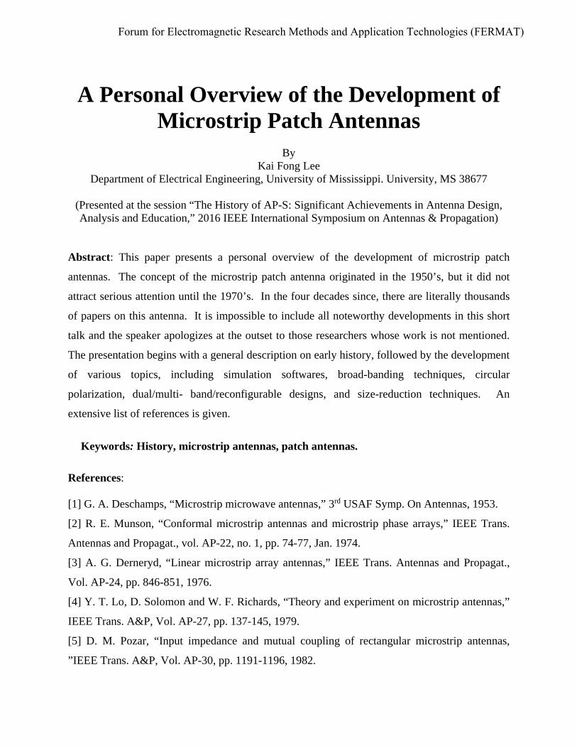
2.5 Reconfigurable patch antennas2.5.1 Frequency reconfigurable designs (a) P. Bhartia, I. Bahl, “A frequency agile microstrip antenna,” IEEE AP-S Int. Symp. Digest, pp. 304-307, 1982.(b) D. H. Schaubert, F. G. Farrar, A. R. Sindoris, and S. T. Hayes, “Microstripantennas with frequency agility and polarization diversity,” IEEE Trans. Antennas Propagat., Vol. AP-29, pp. 118-123, 1981.
(a) Resonant frequency versus bias voltage for a varactor-loaded rectangular patch antenna.
IE3D
(b) Resonant frequency versus separation of posts for 6.2 × 9.0 cm rectangular patch antenna with εr = 2.55, t = 1.6 mm.

Copyright © Dr. Kai-Fong Lee 29
(c) Tuning by Means of an Adjustable Air-gap
K. F. Lee, K. Y. Ho and J. S. Dahele, Circular-disc microstrip antenna withan air gap, IEEE Trans. Antennas & Propagat., AP-32, 880-884, 1984.
z Conducting patchSubstrate
εr
Spacer
Ground plane
Air gap ∆
t
Geometry of a microstrip patch antenna with an air gap
( ) ( )0nmeff
f f εε
∆ =
( )( )eff
r
ttε
εε
+ ∆=
+ ∆
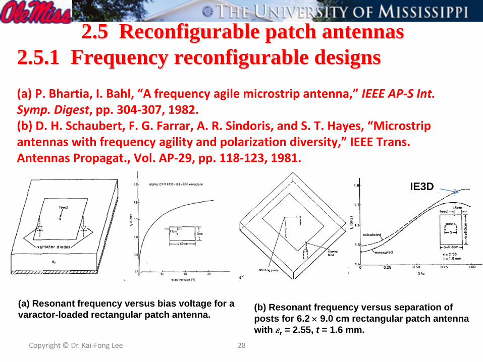
(d) F. Yang and Y. Rahmat-Samii, “Patch antenna with switchable slot (PASS) in wireless communications: concepts, designs and applications,” IEEE Antennas and Propagation Magazine, Vol. 47, No. 2, pp. 13-29, 2005.
X
Patch antenna with a switchable slot (PASS) for Measured frequency response operationdual-band operation
x
zPatch
h
Ground plane
PS
x
y
Probe
Side View
L
W(Xf,Yf)
WS
LS
εr
Top View

(e) S.L.S. Yang, A.A. Kishk, K.F. Lee, "Frequency Reconfigurable U-slot Microstrip Patch Antenna," IEEE AWPL, vol. 7, pp. 127-129, 2008.
Measured return loss with different capacitance value obtained by
rotating the trimmer
Geometry of the tuning circuit (back side of the antenna)
-x
ySMA connector
50 ohm microstrip line
feed
lump components
Ground plane
-40
-35
-30
-25
-20
-15
-10
-5
0
1 1.5 2 2.5 3 3.5 4R
etur
n lo
ss (d
B)
Frequency (GHz)
Higher C (1.5pF)Series3Series4Series5Series6Series7Series8Lower C (0.4pF)

2.5.2 Polarization reconfigurable designs
x
y
PS
L
WS
1
2 LS
(Xf,Yf)
Side Viewxh
Probe
εr
Top View
z
______ LHCP; Diode 1 ON, 2 OFF _ _ _ _ RHCP; Diode 1 OFF, 2 ON
A. Square patch with switching diodes B. Patch with switchable slots (PASS)(Schubert et al. 1981) (Yang et al. 2002)
Feed
Shorting posts
x
y
a
S
0

C. Polarization reconfigurable Modified E patchA. Khidre, K. F. Lee, F. Yang, A. Z. Elsherbeni, IEEE Trans. AP, vol. 61, pp.960-964, 2013
33
S tate 1 State 2 State 3 State 4
State Switch 1 Switch 2
Frequency Polarization
1 OFF OFF fL LP
2 ON ON fH LP
3 ON OFF f LHCP
4 OFF ON f RHCP
fL f fH frequency
Illustrating four states of polarization

Same principle applies to the U-slot patch
U-Slot Patch with Reconfigurable PolarizationQin et al. IEEE Antennas Wireless Propag. Lett. Vol. 9, pp. 1092-1095, 2010.

35
3.6 Size Reduction TechniquesThe size of the patch can be reduced by using high dielectric constant. However, the resulting patch antenna will have narrow impedance bandwidth. This motivates the search for other size reduction methods.
Shorted Quarter Wave PatchBy placing a shorting wall along the null in the electric field across the center of the patch, the resonant length can be reduced by a factor of two (Pinhas & Shtrikman 1988; Chair et al. 1999; Lee et al. 2000). The area occupied by the patch will be reduced by a factor of four, if the aspect ratio is kept the same.
(a) Top view; (b) Side view.

36
Patches with Shorting Pin and Folded Patch Antennas A suitably placed shorting pin can reduce the resonant length of a circular patch by a factor of three, and the area of the patch by a factor of nine (Waterhouse et al. 1998). . Broadbanding techniques such as stacked patches, U-slot patch, and L-probe fed can be applied to obtain small size wideband patch antennas (Shackelford et al. 2003). All these methods result in radiation patterns with high cross polarization. This may not be a disadvantage in indoor mobile communication applications. A low cross polarization design is that of the folded patch, which, however, is thicker and more difficult to fabricate (Luk, Chair, and Lee 1998).
Circular (a) and rectangular (b) patches with shorting pin.
Example of the folded patch antennas.

37
Other methods include modification of the ground plane to increase the current path and the use of metamaterials to manipulate the permittivity as well as the permeability.
The above methods were originally developed for linearly polarized patch antennas. Suitably modify, they can also be applied to reduce the patch size of circularly polarized patch antennas. For details, see:
● H.Wong, K. M. Luk, C.H.Chan, Q. Xue, K. K. So and H. W. Lai, “Small antennas in wireless communications,” IEEE Proc. Vol. 100, pp. 2109-2121, 2012.
A summary of the characteristics, advantages and disadvantages of various miniaturization techniques is given by a recent review article:
● M. U. Khan, M. S. Sharawi, R. Mittra, “Microstrip patch antennas miniaturisation techniques: a review”, IET Microwaves, Antennas & Propagation, vol. 9, pp.913-922, 2015.

Copyright © Dr. Kai-Fong Lee 38
REFERENCESA list of references can be found in the abstract published in theConference Proceedings.
Apologies to those authors whose valuable contributions I haveneither time nor space to mention.