
A New System of Frequency Modulationedmunds/Tube_FM_Exciter_Transmitter/... · A New System of...
8
Proceedings of the I.R.E. and Waves and Electrons January 1947 A New System of Frequency Modulation ROBERT ADLER, ASSOCIATE, I.R.E. Zenith Radio Corporation, Chicago, Illinois. Decimal classification: R148.2XR339. Original manuscript received by the Institute, February 4, 1946; revised manuscript received,-August 14, 1946. Presented, Winter Technical Meeting, New York, N. Y., January 24, 1946. Summary - The development of a new phase-modulator tube is described. In a concentric structure of conventional dimensions, a radial electron stream is shaped into a wave-like pattern which progresses continuously around the cathode. Phase shift, 12 to 16 times larger than in conventional modulators, is produced by electro-magnetic deflection. The failings of early models are analyzed and the steps are reviewed which resulted in the development of a satisfactory tube structure. THE PHASITRON system of frequency modulation, which has recently come into practical use, is based on a new tube structure. It is the object of this paper to review the development of this structure from its initial concept to the point where all technical requirements for hi-h-fidelity broadcasting as well as for communication transmitters were met by laboratory models. The step from the laboratory model to the production model and the design of complete high-fidelity transmitters incorporating the new modulator have already been described in the literature.[1] Two different types of frequency-modulation transmitters have heretofore been widely used, based on reactance modulators and phase modulators. In transmitters using a reactance modulator, devices are required for continuous automatic correction of the aver age carrier frequency with respect to a crystal oscillator The frequency actually transmitted is then a function of the correction-system parameters and is not solely dependent on the crystal oscillator. Transmitters employing conventional phase modulators use a total frequency multiplication of several thousand times to obtain full rated deviation at the lowest audio frequencies. This high factor of multiplication requires two separate multiplier chains with frequency conversion between them, involving large numbers of tubes and circuits which present a number of problems with respect to random noise and spurious beat notes. While none of these difficulties could be regarded as insurmountable, it appeared that crystal-controlled frequency-modulation transmitters could be simplified and perhaps improved in some respects if a phase modulator were known which would produce phase excursions far in excess of those obtainable with conventional modulators. This thought stood at the beginning of the development. Analysis of an idea by C. W. Carnahan, who had proposed a mechanical phase modulator, indicated that inertia forces would make such a device impractical if not impossible; it appeared that only a vacuum tube could do the job. To operate efficiently in connection with conventional circuits and loads, such a tube would have to work with anode voltages and currents comparable to common receiver tubes. It seemed that this could be most easily accomplished if the usual concentric arrangement of anode and cathode were retained. Fig. 1-Original concept of the phasitron modulator: a rotating bundle of electron beams. With these rather broad directions in mind, let us now study the fundamental concept of the new phase modulator. Let us assume that by some device in the black central portion of Fig. 1 the electrons which fly radially, away from the cathode are split into discrete radial beams-twelve are shown in this figure - and that the first anode consists of twelve bars, all connected. Let us further assume that the device in the center rotates, with uniform speed, so that the electron beams alternately hit the twelve bars which constitute the first anode,
Transcript of A New System of Frequency Modulationedmunds/Tube_FM_Exciter_Transmitter/... · A New System of...
Proceedings of the I.R.E. and Waves and ElectronsJanuary 1947
A New System of Frequency ModulationROBERT ADLER, ASSOCIATE, I.R.E.
Zenith Radio Corporation, Chicago, Illinois.
Decimal classification: R148.2XR339. Original manuscript received by the Institute,February 4, 1946; revised manuscript received,-August 14, 1946. Presented, WinterTechnical Meeting, New York, N. Y., January 24, 1946.
Summary - The development of a new phase-modulatortube is described. In a concentric structure ofconventional dimensions, a radial electron stream isshaped into a wave-like pattern which progressescontinuously around the cathode. Phase shift, 12 to 16times larger than in conventional modulators, isproduced by electro-magnetic deflection.
The failings of early models are analyzed and the steps arereviewed which resulted in the development of asatisfactory tube structure.
THE PHASITRON system of frequency modulation,which has recently come into practical use, is based on anew tube structure. It is the object of this paper to reviewthe development of this structure from its initial concept tothe point where all technical requirements for hi-h-fidelitybroadcasting as well as for communication transmitterswere met by laboratory models. The step from thelaboratory model to the production model and the design ofcomplete high-fidelity transmitters incorporating the newmodulator have already been described in the literature.[1]
Two different types of frequency-modulation transmittershave heretofore been widely used, based on reactancemodulators and phase modulators. In transmitters using areactance modulator, devices are required for continuousautomatic correction of the aver age carrier frequency withrespect to a crystal oscillator The frequency actuallytransmitted is then a function of the correction-systemparameters and is not solely dependent on the crystaloscillator. Transmitters employing conventional phasemodulators use a total frequency multiplication of severalthousand times to obtain full rated deviation at the lowestaudio frequencies. This high factor of multiplicationrequires two separate multiplier chains with frequencyconversion between them, involving large numbers oftubes and circuits which present a number of problemswith respect to random noise and spurious beat notes.
While none of these difficulties could be regarded asinsurmountable, it appeared that crystal-controlledfrequency-modulation transmitters could be simplified and
perhaps improved in some respects if a phase modulatorwere known which would produce phase excursions far inexcess of those obtainable with conventional modulators.
This thought stood at the beginning of the development.Analysis of an idea by C. W. Carnahan, who had proposeda mechanical phase modulator, indicated that inertia forceswould make such a device impractical if not impossible; itappeared that only a vacuum tube could do the job. Tooperate efficiently in connection with conventional circuitsand loads, such a tube would have to work with anodevoltages and currents comparable to common receivertubes. It seemed that this could be most easilyaccomplished if the usual concentric arrangement of anodeand cathode were retained.
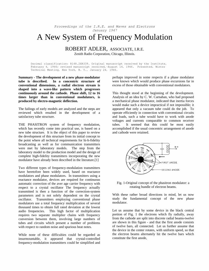
Fig. 1-Original concept of the phasitron modulator: arotating bundle of electron beams.
With these rather broad directions in mind, let us nowstudy the fundamental concept of the new phasemodulator.
Let us assume that by some device in the black centralportion of Fig. 1 the electrons which fly radially, awayfrom the cathode are split into discrete radial beams-twelveare shown in this figure - and that the first anode consistsof twelve bars, all connected. Let us further assume thatthe device in the center rotates, with uniform speed, so thatthe electron beams alternately hit the twelve bars whichconstitute the first anode,
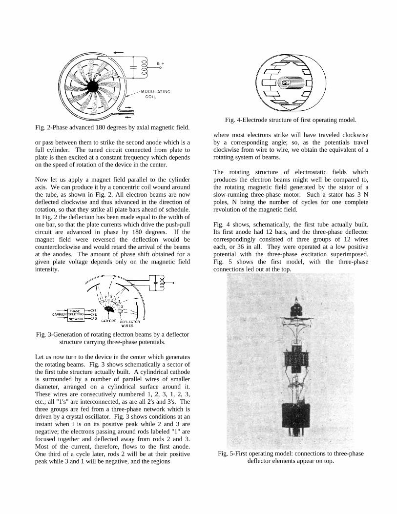
Fig. 2-Phase advanced 180 degrees by axial magnetic field.
or pass between them to strike the second anode which is afull cylinder. The tuned circuit connected from plate toplate is then excited at a constant frequency which dependson the speed of rotation of the device in the center.
Now let us apply a magnet field parallel to the cylinderaxis. We can produce it by a concentric coil wound aroundthe tube, as shown in Fig. 2. All electron beams are nowdeflected clockwise and thus advanced in the direction ofrotation, so that they strike all plate bars ahead of schedule.In Fig. 2 the deflection has been made equal to the width ofone bar, so that the plate currents which drive the push-pullcircuit are advanced in phase by 180 degrees. If themagnet field were reversed the deflection would becounterclockwise and would retard the arrival of the beamsat the anodes. The amount of phase shift obtained for agiven plate voltage depends only on the magnetic fieldintensity.
Fig. 3-Generation of rotating electron beams by a deflectorstructure carrying three-phase potentials.
Let us now turn to the device in the center which generatesthe rotating beams. Fig. 3 shows schematically a sector ofthe first tube structure actually built. A cylindrical cathodeis surrounded by a number of parallel wires of smallerdiameter, arranged on a cylindrical surface around it.These wires are consecutively numbered 1, 2, 3, 1, 2, 3,etc.; all "1's" are interconnected, as are all 2's and 3's. Thethree groups are fed from a three-phase network which isdriven by a crystal oscillator. Fig. 3 shows conditions at aninstant when I is on its positive peak while 2 and 3 arenegative; the electrons passing around rods labeled "1" arefocused together and deflected away from rods 2 and 3.Most of the current, therefore, flows to the first anode.One third of a cycle later, rods 2 will be at their positivepeak while 3 and 1 will be negative, and the regions
Fig. 4-Electrode structure of first operating model.
where most electrons strike will have traveled clockwiseby a corresponding angle; so, as the potentials travelclockwise from wire to wire, we obtain the equivalent of arotating system of beams.
The rotating structure of electrostatic fields whichproduces the electron beams might well be compared to,the rotating magnetic field generated by the stator of aslow-running three-phase motor. Such a stator has 3 Npoles, N being the number of cycles for one completerevolution of the magnetic field.
Fig. 4 shows, schematically, the first tube actually built.Its first anode had 12 bars, and the three-phase deflectorcorrespondingly consisted of three groups of 12 wireseach, or 36 in all. They were operated at a low positivepotential with the three-phase excitation superimposed.Fig. 5 shows the first model, with the three-phaseconnections led out at the top.
Fig. 5-First operating model: connections to three-phasedeflector elements appear on top.
The tube was first tried out with a carrier frequency of 60cycles. The push-pull output circuit was connectedthrough a transformer to the oscilloscope and the sweepsynchronized from one terminal of the three-phase input.A coil was arranged around the tube to produce the axialmagnet field; it was fed from a variable direct currentsupply so that the phase shift could be accurately plotted asa function of current through the coil. Plus and minus 720degrees-or plus and minus two complete cycles-wereobtained with this first tube.
Fig. 6-Frequency-modulation broadcast transmitter,showing (left to right): 235-kilocycle crystal, oscillatortube, three-phase network, modulator tube with audio
deflection coil, push-pull output transformer, first doubler,frequency multipliers to 45.1 megacycles.
Next, a complete frequency-modulation transmitter wasbuilt (see Fig. 6), which consisted of a crystal oscillator on235 kilocycles, a simple phase-splitting network, themodulator tube, and a string of multipliers to reach thefinal frequency of 45.1 megacycles. The totalmultiplication was only 192 times.
Using the full 720 degrees phase excursion, this transmitterwas capable of 75 kilocycles deviation at an audiofrequency of 30 cycles. A similar unit, using the samemultiplication, was built to operate as exciter for Zenith's50,000-watt station, WWZR, and several successful testtransmissions were made over this station.
Only a fraction of one watt of audio power was needed forthe modulating coil. The inductance of this coil isinstrumental in obtaining constant frequency deviationover the entire audio band; with a constant voltage appliedto the coil, this inductance tends to make the current, andconsequently the phase shift, inversely proportional to thefrequency of the audio signal. This is exactly thecharacteristic required to obtain constant deviation.
The first model of the new modulator tube had severalfailings. Most apparent was the low signal output: withone milliampere direct current on each anode,
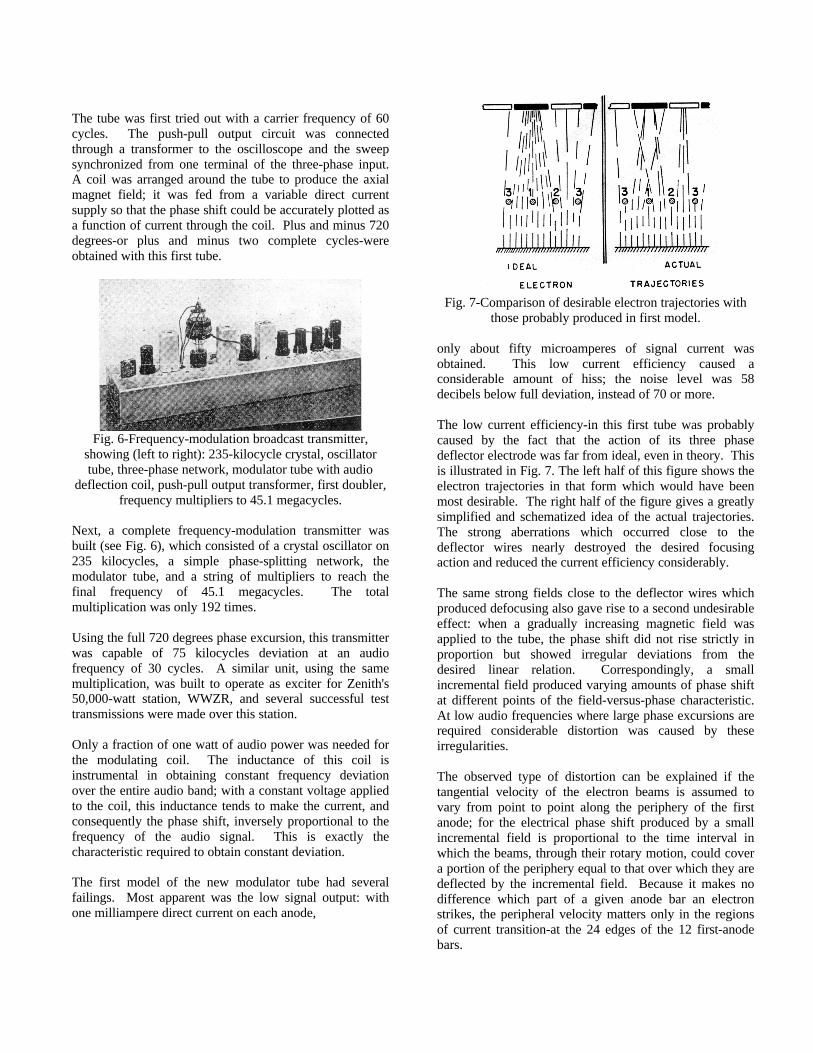
Fig. 7-Comparison of desirable electron trajectories withthose probably produced in first model.
only about fifty microamperes of signal current wasobtained. This low current efficiency caused aconsiderable amount of hiss; the noise level was 58decibels below full deviation, instead of 70 or more.
The low current efficiency-in this first tube was probablycaused by the fact that the action of its three phasedeflector electrode was far from ideal, even in theory. Thisis illustrated in Fig. 7. The left half of this figure shows theelectron trajectories in that form which would have beenmost desirable. The right half of the figure gives a greatlysimplified and schematized idea of the actual trajectories.The strong aberrations which occurred close to thedeflector wires nearly destroyed the desired focusingaction and reduced the current efficiency considerably.
The same strong fields close to the deflector wires whichproduced defocusing also gave rise to a second undesirableeffect: when a gradually increasing magnetic field wasapplied to the tube, the phase shift did not rise strictly inproportion but showed irregular deviations from thedesired linear relation. Correspondingly, a smallincremental field produced varying amounts of phase shiftat different points of the field-versus-phase characteristic.At low audio frequencies where large phase excursions arerequired considerable distortion was caused by theseirregularities.
The observed type of distortion can be explained if thetangential velocity of the electron beams is assumed tovary from point to point along the periphery of the firstanode; for the electrical phase shift produced by a smallincremental field is proportional to the time interval inwhich the beams, through their rotary motion, could covera portion of the periphery equal to that over which they aredeflected by the incremental field. Because it makes nodifference which part of a given anode bar an electronstrikes, the peripheral velocity matters only in the regionsof current transition-at the 24 edges of the 12 first-anodebars.

If we assume an irregular distribution of tangentialvelocities around the periphery, the average of thevelocities measured at the 24 edges may well be differentfrom the average taken over the whole periphery; then, ifwe rotate the entire system of velocities by applying
Fig. 8-Schematic view of transverse deflector arrangement.
an axial magnetic field, those velocities appearing at the 24edges-and consequently their average-are bound to vary.In a position where this average is high, a largerincremental field is required to produce a given incrementof phase.
There can be little-doubt regarding the existence of anirregular distribution of tangential velocities in the tubestructure described. Cyclic variations (one cycle for eachdeflector wire) were bound to be present, and because therewere 1'2 wires for every edge, all even harmonics of suchcyclic variations would appear in phase on all edges. Moredetailed study of the distortion effect tended to verify theabove analysis. In the following we shall refer to thiseffect as "structural distortion."
Two more tubes were built which differed from the firstonly in detail. Their performance was quite similar.
If the new, phase modulator was to meet practicalrequirements it seemed that the signal output would haveto be at least five times higher for the same direct currenton the plates, and the structural distortion would have to besubstantially suppressed. An entirely different deflectorsystem was needed which would produce a smoothlyrotating electrostatic field without noticeable speedvariations from point to point.
Fig. 8 illustrates the principle of a new deflector systemdesigned to produce such a field. Two rows of shortparallel wires face each other across a center plane. Eachrow consists of three groups which are interlaced andconnected to a three-phase supply as before. The directionin which the voltages travel is the same in both rows, butthe wires "I" in one row face the middle between the wires"2" and '3" in the other. A transverse electric field (vertical
in Fig. 8) is produced in the center plane between the tworows, and if we plot this field at a given instant from left toright along the center plane we find that it varies quitesmoothly, very much like a sine function. Because theindividual deflector wires are not in the immediate vicinityof the center plane, their strong local fields can no longerupset the smooth character of the field distribution.
To save time-consuming computation of the field along thecenter plane, an electrolytic model was built as shown inFig. 9. On each of two bakelite bars, three bare wires werewound interlaced.
Fig. 9-Electrolytic model for the study of transversedeflectors.
Three stationary voltages, corresponding to aninstantaneous condition of a three-phase system, wereapplied to the wires on each bar. The short portions ofthese wires which faced each other across the gaprepresented the deflector elements shown schematically inFig. 8. A two-element probe was moved along the gapbetween the bars by means of a lead screw. The twoelements were positioned symmetrically on a lineperpendicular to the center plane, and the potential of eachelement was plotted with reference to the three-phaseneutral. Fig. 10 shows one of these plots, which not onlyproved that a field distribution closely approaching a sinefunction could be produced but also yielded data on theintensity of the transverse field as a function ofconfiguration.
To utilize a deflection system of this new kind in aconcentric tube structure, the two parallel rows of shortwires had to be bent so as to form two parallel coaxialcircles, and the electron flow had to be so arranged that allelectrons would travel radially and pass near the centerplane between the two deflectors.@ This led to the conceptillustrated in Fig. 1 1. The electrons are shown here in theshape of a sharp-edged disk from which one quarter hasbeen cut away so that the lower deflector becomes partly
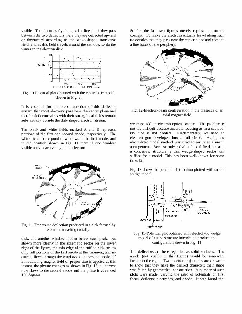
visible. The electrons fly along radial lines until they passbetween the two deflectors; here they are deflected upwardor downward according to the wave-shaped transversefield; and as this field travels around the cathode, so do thewaves in the electron disk.
Fig. 10-Potential plot obtained with the electrolytic modelshown in Fig. 9.
It is essential for the proper function of this deflectorsystem that most electrons pass near the center plane andthat the deflector wires with their strong local fields remainsubstantially outside the disk-shaped electron stream.
The black and white fields marked A and B representportions of the first and second anode, respectively. Thewhite fields correspond to windows in the first anode, andin the position shown in Fig. 11 there is one windowvisible above each valley in the electron
Fig. 11-Transverse deflection produced in a disk formed byelectrons traveling radially.
disk, and another window hidden below each peak. Asshown more clearly in the schematic sector on the lowerright of the figure, the thin edge of the ruffled disk strikesonly full portions of the first anode at this moment, and nocurrent flows through the windows to the second anode. Ifa modulating magnet field of proper size is applied at thisinstant, the picture changes as shown in Fig. 12; all currentnow flows to the second anode and the phase is advanced180 degrees.
So far, the last two figures merely represent a mentalconcept. To make the electrons actually travel along suchtrajectories that they pass near the center plane and come toa line focus on the periphery,
Fig. 12-Electron-beam configuration in the presence of anaxial magnet field.
we must add an electron-optical system. The problem isnot too difficult because accurate focusing as in a cathode-ray tube is not needed. Fundamentally, we need anelectron gun developed into a full circle. Again, theelectrolytic model method was used to arrive at a usefularrangement. Because only radial and axial fields exist ina concentric structure, a thin wedge-shaped sector willsuffice for a model. This has been well-known for sometime. [2]
Fig. 13 shows the potential distribution plotted with such awedge model.
Fig. 13-Potential plot obtained with electrolytic wedgemodel of.a tube structure intended to produce the
configuration shown in Fig. 11.
The deflectors are here regarded as solid surfaces. Theanode (not visible in this figure) would be somewhatfarther to the right. Two electron trajectories are drawn into show that they have the desired character; their shapewas found by geometrical construction. A number of suchplots were made, varying the ratio of potentials on firstfocus, deflector electrodes, and anode. It was found that

the deflectors had to be longer in the direction of electrontravel than had been anticipated; but instead of making thelittle wires longer, a solid ring was laid around eachdeflector electrode and the two rings brought out to aseparate contact.
Fig. 14 shows the tube layout which resulted from theseplots. Around the cathode there are two cylinders -the firstfocusing electrode.
Fig. 14-Section of improved tube structure. Modulatingflux is concentrated between edges of second focusing
electrodes.
Next come the two deflectors which carry the short radialwires; they are surrounded by the two rings just mentioned,called the second focusing electrode. These rings are madeof soft iron and continued outside the supporting micas bymore soft iron; they help to concentrate the modulatingmagnet field into a narrow region, as indicated by thedotted lines. Finally, the anodes A and B terminate theconcentric structure.
Fig. 15-Three-phase deflector electrode, mounted togetherwith first and second focusing electrodes. Two suchassemblies faced each other in the completed tube.
Fig. 15 shows one of the deflectors with the 36 short radialwires and the first and second focusing electrodes mountedon one mica.
In the first tube of this new kind, the checkerboard patternof anode fields A and B was made up of 24 rectangular
metal fins, 12 to each anode, all lying in one cylindricalplane and properly interconnected.
Results with the new model were most encouraging. Withcareful adjustment of the focusing potentials the structuraldistortion could be almost entirely eliminated; currentefficiency was improved by a factor of three or four, andthe hiss level was reduced by a much larger factor,probably because the electron stream was no longerintercepted by a positive grid. With a total multiplicationof 192 times, the hiss was now more than 70 decibelsbelow full deviation.
The new modulator operated with very low distortiondown to about 100 cycles. But at the very large phaseexcursions required for 50 cycles at this low multiplication,nonlinear distortion appeared. It was mostly of the third-harmonic type, quite similar to that which conventionalphase modulators produce when they are used over toowide an angle. Fig. 16 shows the geometrical reasons forthis type of distortion; for large deflections, the arc whichthe electron trajectories cover on the periphery of the tubeincreases faster than the angle of deflection, so that thegraph of phase shift versus magnet field becomes steeperin the regions of large phase shift.
Fig. 16-Nonlinearity at large phase excursions. Distortionis reduced by concentrating the region where deflection
occurs.
The figure also shows that it is better to concentrate the'magnet field close to the center, rather than spread it outover the whole tube. It was for this reason that the secondfocusing electrodes were made of soft iron.
To suppress the nonlinearity just explained, a number ofmethods were open. The most straightforward solutionwould consist in introducing a controlled amount ofsaturation into the magnetic path so that strong fieldswould be reduced by just the right amount. Anothersolution consists in driving the deflection coil from a pairof pentodes in push -pull, so adjusted that their combinedtransconductance is peaked at the operating point. With amodulator built according to this idea, total distortion at 50cycles and full deviation could be reduced to 1.35 per centwith a multiplication of only 192 times. The

corresponding phase excursion was plus and minus 430degrees.
In the further course of the development, the hiss level wasreduced to such an extent that, at the present time, it isconsidered more convenient to double the multiplicationand dispense entirely with any artificial means oflinearization.
A few words about the circuits used to produce the three-phase excitation might be in order at this point. Originally,the simple resistance-capacitance network on the right inFig. 17 had been used in all experiments.
Fig. 17-Networks for generating three-phase potentials.
Later it was found that good wave form on the deflectorelectrodes was important for reducing distortion to aminimum, and the network on the left, derived from thewell-known Scott circuit, was substituted.
The tube described above might have been used infrequency-modulation broadcast transmitters, but its outputlevel was still inconveniently low, and certainly too low foruse in communication transmitters. Checking into thecauses for the low output, it was found that there existed aresistance of only, about 10,000 ohms between the twoanodes, evidently as a consequence of secondary emission.Such secondary emission would reduce the radio-frequency component of the anode current, even withoutload, because the anode struck by more electrons wouldalso emit more secondaries. In addition, only low-impedance load circuits could be used. In the first tube ofthe new kind the anode fields A and B were arranged sideby side, and a direct-current voltage applied between themwould only draw all current to the more positive anode. Adifferent anode structure appeared necessary to suppresssecondary emission effects.
A tube was then built with an anode structure as shown inFig. 18. This, in effect, is a return to the original model inwhich holes in the first anode represented the active partsof the second; but this time, a helical suppressor was setbetween the two anodes.
Fig. 18-Arrangement of first anode, suppressor, and secondanode in last experimental model.
Fig. 19 shows an X-ray photograph of this lastexperimental model. The two deflectors with their littlewires, the outer focusing rings with their magneticextensions, the checkerboard fields of the first anode,
Fig. 19-X-ray view of last experimental model. Electrodesinside the suppressor helix may be identified by
comparison with Fig. 14.
and finally the suppressor and the second anode appear inthis picture. The current efficiency of this tube was severaltimes that of the previous model; the signal component wasequal to more than half the direct current on each plate.The output impedance was several megohms. The hisslevel, with a multiplication of 192 times, could not bemeasured accurately; with twice that multiplication, it wasfound to be 78 decibels below full deviation.
The large output from this tube made it possible to use it ina communication transmitter (see Fig. 20). Here, a crystaloscillator was used to drive a three phase network at 8.37megacycles. In the output from the phase-modulator tube,a high-inductance permeability-tuned load circuit delivered30 volts into the grid of a 6AC7 tube operating asquadrupler.
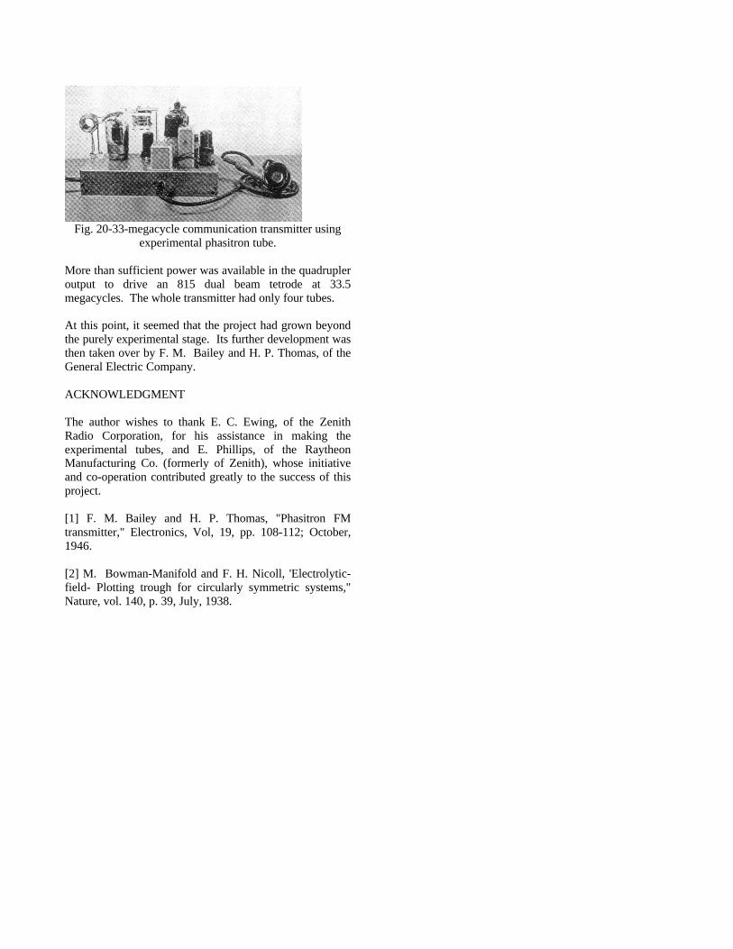
Fig. 20-33-megacycle communication transmitter usingexperimental phasitron tube.
More than sufficient power was available in the quadrupleroutput to drive an 815 dual beam tetrode at 33.5megacycles. The whole transmitter had only four tubes.
At this point, it seemed that the project had grown beyondthe purely experimental stage. Its further development wasthen taken over by F. M. Bailey and H. P. Thomas, of theGeneral Electric Company.
ACKNOWLEDGMENT
The author wishes to thank E. C. Ewing, of the ZenithRadio Corporation, for his assistance in making theexperimental tubes, and E. Phillips, of the RaytheonManufacturing Co. (formerly of Zenith), whose initiativeand co-operation contributed greatly to the success of thisproject.
[1] F. M. Bailey and H. P. Thomas, "Phasitron FMtransmitter," Electronics, Vol, 19, pp. 108-112; October,1946.
[2] M. Bowman-Manifold and F. H. Nicoll, 'Electrolytic-field- Plotting trough for circularly symmetric systems,"Nature, vol. 140, p. 39, July, 1938.